

Page 1

OPERATOR'S MANUAL
CLASS B AIS TRANSPONDER
Model
FA-70
www.furuno.com
Page 2
The paper used in this manual
9-52 Ashihara-cho,
A:FEB
2020
.
C1:AUG.15, 2022
Pub. No.
(
)
Nishinomiya, 662-8580, JAPAN
is elemental chlorine free.
・FURUNO Authorized Distributor/Dealer
All rights reserved.
TEHI
FA-70
Printed in Japan
OME-45150-C1
0 0 0 1 9 7 4 0 2 1 2
Page 3
IMPORTANT NOTICES
General
• This manual has been authored with simplified grammar, to meet the needs of international users.
• The operator of this equipment must read and follow the instructions in this manual.
Wrong operation or maintenance can void the warranty or cause injury.
• Do not copy any part of this manual without written permission from FURUNO.
• If this manual is lost or worn, contact your dealer about replacement.
• The contents of this manual and the equipment specifications can change without notice.
• The example screens (or illustrations) shown in this manual can be different from the screens you
see on your display. The screens you see depend on your system configuration and equipment
settings.
• Save this manual for future reference.
• Any modification of the equipment (including software) by persons not authorized by FURUNO will
void the warranty.
• The following concern acts as our importer in Europe, as defined in DECISION No 768/2008/EC.
- Name: FURUNO EUROPE B.V.
- Address: Siriusstraat 86, 5015 BT, Tilburg, The Netherlands
• The following concern acts as our importer in UK, as defined in SI 2016/1025 as amended SI 2019/
470.
- Name: FURUNO (UK) LTD.
- Address: West Building Penner Road Havant Hampshire PO9 1QY, U.K.
• Microsoft and Windows are registered trademarks or trademarks of the Microsoft Corporation of
the USA and other countries.
• All brand, product names, trademarks, registered trademarks, and service marks belong to their
respective holders.
How to discard this product
Discard this product according to local regulations for the disposal of industrial waste. For disposal in
the USA, see the homepage of the Electronics Industries Alliance (http://www.eiae.org/) for the
correct method of disposal.
How to discard a used battery
Some FURUNO products have a battery(ies). To see if your product has a battery, see the chapter
on Maintenance. If a battery is used, tape the + and - terminals of the battery before disposal to prevent fire, heat generation caused by short circuit.
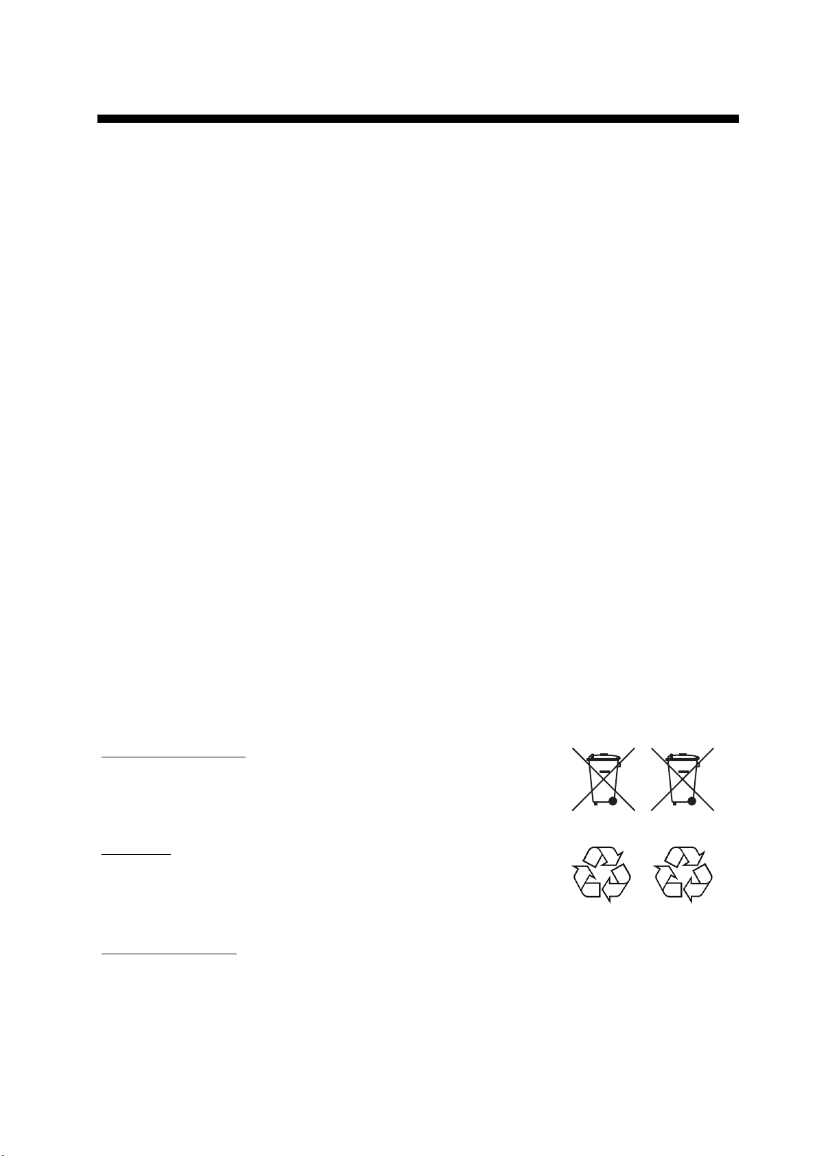
In the European Union
The crossed-out trash can symbol indicates that all types of batteries
must not be discarded in standard trash, or at a trash site. Take the
used batteries to a battery collection site according to your national
legislation and the Batteries Directive 2006/66/EU.
In the USA
The Mobius loop symbol (three chasing arrows) indicates that
Ni-Cd and lead-acid rechargeable batteries must be recycled.
Take the used batteries to a battery collection site according to
local laws.
In the other countries
There are no international standards for the battery recycle symbol. The number of symbols can increase when the other countries make their own recycle symbols in the future.
Ni-Cd Pb
Cd
i
Page 4
SAFETY INSTRUCTIONS
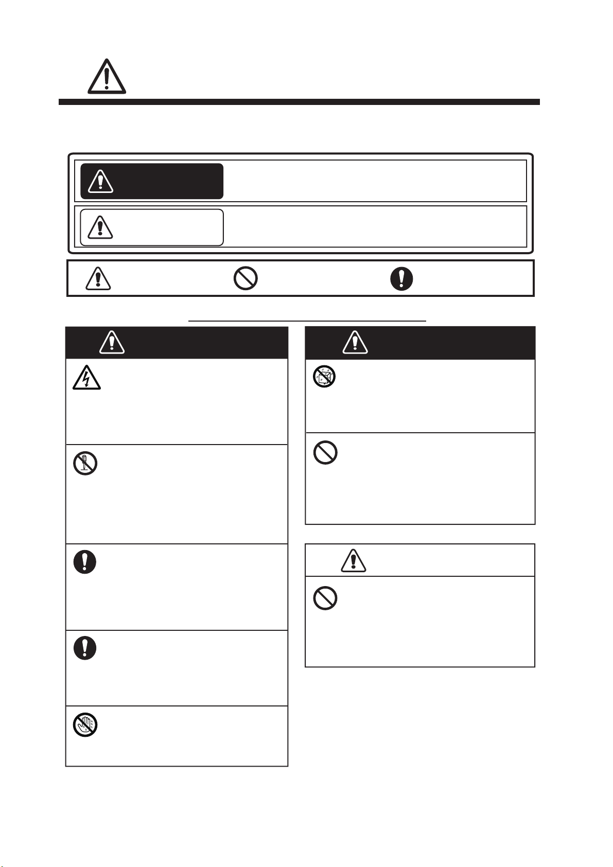
Indicates a potentially hazardous situation which, if not
avoided, could result in death or serious injury.
Indicates a potentially hazardous situation which, if not
avoided, could result in minor or moderate injury.
WARNING
CAUTION
WARNING
Do not open the equipment.
This equipment uses high voltage
that can cause electrical shock.
Only qualified personnel can
work inside the equipment.
Turn off the power immediately
if water leaks into the
equipment or smoke or fire is
coming from the equipment.
Fire or electrical shock can result.
Make sure no rain or water
splash leaks into the equipment.
Fire or electrical shock can result if
water leaks into the equipment.
Use the correct fuse.
Use of a wrong fuse can cause
fire or serious damage to the
equipment.
Do not place liquid-filled
containers on or near the
equipment.
Fire or electrical shock can result
if a liquid spills into the equipment.
Warning, Caution Prohibitive Action Mandatory Action
Safety Instructions for the Operator
Do not disassemble or modify
the equipment.
Fire, electrical shock or serious
injury can occur. If the equipment
does not work properly, contact
your dealer.
Do not operate the equipment
with wet hands.
Electrical shock can result.
WARNING
CAUTION
Do not disconnect the power
cable while the system is
powered.
Damage to the equipment can
result.
The operator and installer must read the applicable safety instructions before attempting to install
or operate the equipment.
ii
Page 5
WARNING
CAUTION
Turn off the power at the
switchboard before beginning
the installation.
Fire or electrical shock can result
if the power is left on.
Safety Instructions for the Installer
Be sure that the power supply is
compatible with the voltage
rating of the equipment.
Connection of an incorrect power
supply can cause fire or damage
the equipment.
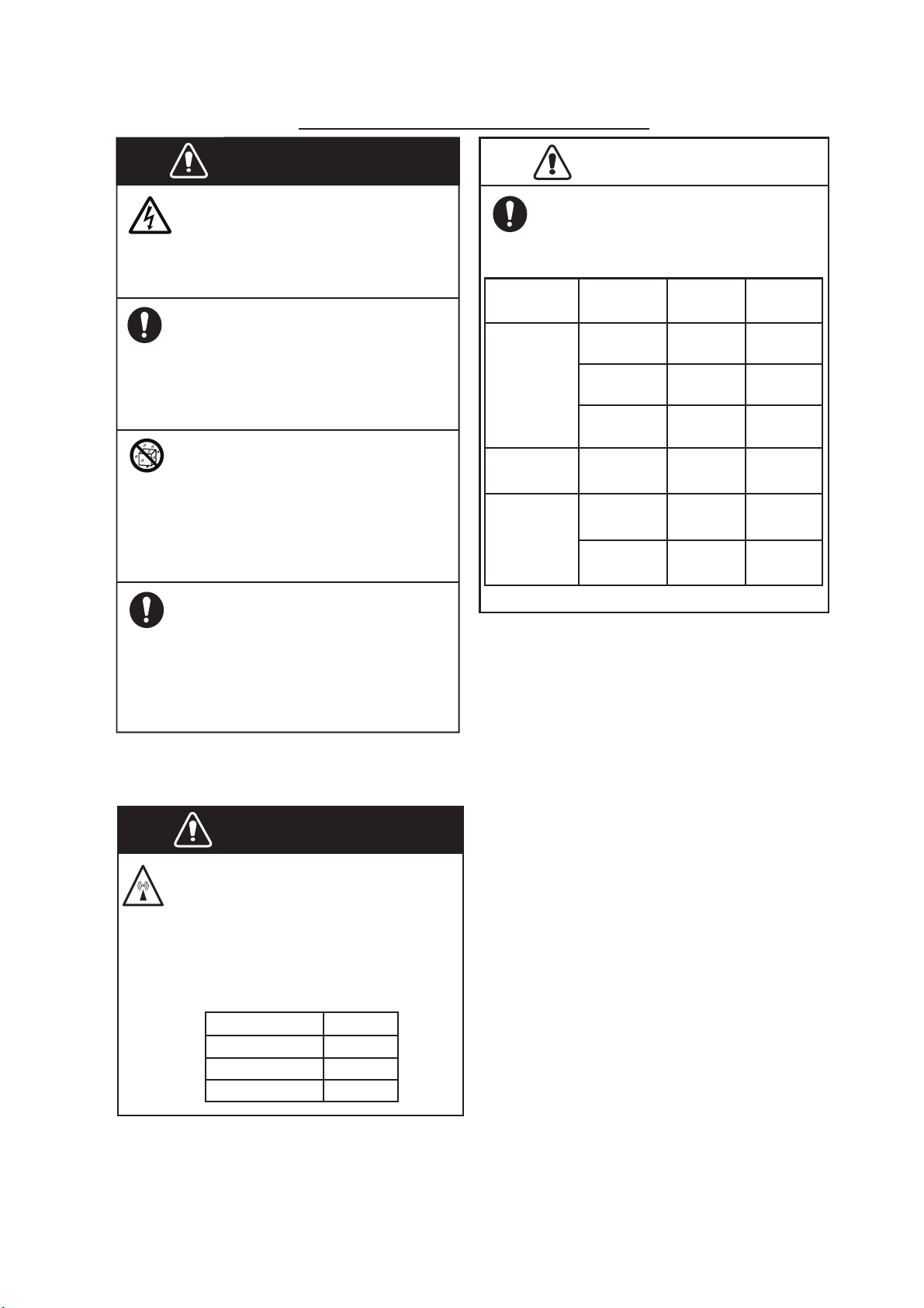
Observe the following compass
safe distances to prevent
interference to a magnetic
compass:
Standard
compass
Steering
compass
Antenna
Unit
Power
Supply Unit
Type
PR-240
Do not install the equipment
where it may get wet from rain
or water splash.
Water in the equipment can result
in fire, electrical shock or damage
to the equipment.
ELECTRICAL SHOCK HAZARD
Do not open the equipment.
Only qualified personnel can work
inside the equipment.
GPA-017S
AIS
Transponder
FA-70
Radiation Hazard
Do not approach the antenna
closer than 0.2 m when it is
transmitting.
The antenna emits radio waves
which can be harmful to the human
body, particularly the eyes.
WARNING
Radiation level
100 W/m
2
10 W/m
2
Distance
GPA-017
0.3 m 0.3 m
0.3 m 0.3 m
0.9 m 0.6 m
N/A
N/A
GPA-C01
0.3 m 0.3 m
0.3 m 0.3 m
2 W/m
2
0.2 m
PR-241
0.85 m 0.55 m
SAFETY INSTRUCTIONS
iii
Page 6

TABLE OF CONTENTS
FOREWORD ....................................................................................................................v
SYSTEM CONFIGURATION .........................................................................................vii
1. INSTALLATION .....................................................................................................1-1
1.1 Equipment List ...........................................................................................................1-1
1.2 Included Items and Local Supplies ............................................................................1-4
1.3 Required Tools and Materials .................................................................................... 1-5
1.4 AIS Transponder FA-70 ............................................................................................. 1-5
1.5 GPS Antenna ............................................................................................................. 1-6
1.6 VHF Antenna (option) ................................................................................................1-7
1.7 AC-DC Power Supply (option) ...................................................................................1-8
1.8 Wiring......................................................................................................................... 1-9
2. SHIP INFORMATION INPUT .................................................................................2-1
2.1 How to Install the Driver.............................................................................................2-1
2.2 How to Install the AIS Setting Tool.............................................................................2-2
2.3 How to Start and Quit the AIS Setting Tool................................................................ 2-3
2.4 Overview of the AIS Setting Tool ...............................................................................2-4
2.5 Initial Setup ................................................................................................................2-5
3. SETTINGS AND STATUS......................................................................................3-1
3.1 IO setup (input/output port) ........................................................................................ 3-1
3.2 Own Vessel Data Screen...........................................................................................3-2
3.3 Alert Status.................................................................................................................3-3
3.4 IO Monitor ..................................................................................................................3-4
4. MAINTENANCE .....................................................................................................4-1
4.1 Maintenance...............................................................................................................4-1
4.2 Replacement of Fuse .................................................................................................4-1
4.3 Troubleshooting .........................................................................................................4-2
4.4 Diagnostics.................................................................................................................4-3
APPX. 1 MENU TREE ..............................................................................................AP-1
APPX. 2 ALERT LISTS ............................................................................................AP-4
APPX. 3 NMEA2000/0183 INPUT/OUTPUT DATA .................................................AP-5
APPX. 4 RADIO REGULATORY INFORMATION ...................................................AP-7
SPECIFICATIONS .....................................................................................................SP-1
PACKING LIST ............................................................................................................A-1
OUTLINE DRAWINGS.................................................................................................D-1
INTERCONNECTION DIAGRAM ................................................................................ S-1
iv
Page 7

FOREWORD
A Word to the Owner of the FA-70
FURUNO Electric Company thanks you for purchasing the FURUNO FA-70 Class B AIS Transponder. We are confident you will discover why the FURUNO name has become synonymous
with quality and reliability.
Since 1948, FURUNO Electric Company has enjoyed an enviable reputation for quality and reliability throughout the world. This dedication to excellence is furthered by our extensive global network of agents and dealers.
Your equipment is designed and constructed to meet the rigorous demands of the marine environment. However, no machine can perform its intended function unless properly operated and
maintained. Please carefully read and follow the operation and maintenance procedures in this
manual.
We would appreciate feedback from you, the end-user, about whether we are achieving our goal.
Thank you for considering and purchasing FURUNO equipment.
Features
The FA-70 is a Class B AIS (Automatic Identification System) capable of exchanging navigation
and ship data between own ship and other ships or coastal stations.
The main features are:
• Fully meets the following regulations: IEC 62287-1, IEC 62287-2
• Switchable communication system; SOTDMA and CSTDMA
• Capable of initial setting from the TZTL12F/15F/TZT2BB (software version: 07.01 or later) or
TZT9F/12F/16F/19F
• Built in VHF splitter
The VHF splitter enables the AIS transponder and VHF transceiver to share a single VHF antenna.
• Capable of easy updating to the latest software
• Meets NMEA2000 requirements
• Static data
• MMSI (Maritime Mobile Service Identity), ship’s name, call sign
• Types of ship and cargo
• Location of position-fixing antenna on the ship
• Dynamic data
• Ship's position with accuracy indication and integrity status
• Universal Time Coordinated (UTC)
• Course over ground (COG)
• Speed over ground (SOG)
v
Page 8

FOREWORD
Usage notes
MMSI
Before commencing installation, ensure you have obtained a MMSI number for your vessel.
In the United States of America, it is a violation of the rules of the Federal Communications Commission to input an MMSI that has not been properly assigned to the end user or to otherwise input
any inaccurate data in this device. The MMSI and Static Data must be entered only by a FURUNO
dealer or other appropriately qualified installer of marine communications equipment on board
vessels.
For other locations, check your local regulations for details regarding MMSI and static data input.
Note: You can enter the MMSI only once. If it becomes necessary to change the MMSI, contact
your dealer.
VHF splitter in the FA-70
• AIS transmission and reception can not be done during the VHF radio transmission.
• A “pop” noise may be generated from the VHF radio during the AIS transmission, however this
is not abnormal as it occurs during AIS transmission.
• Supported VHF radio: 155 MHz to 164 MHz, Power < 25 W
Software used in this product
This product includes software to be licensed under the Apache and BSD.
Program No.
0550263-01.** (** denotes minor modifications.)
CE/UKCA declaration
With regards to CE/UKCA declarations, please refer to our website (www.furuno.com), for further
information on RoHS conformity declarations.
Disclosure of Information about China RoHS
With regards to China RoHS information for our products, please refer to our website
(www.furuno.com).
vi
Page 9
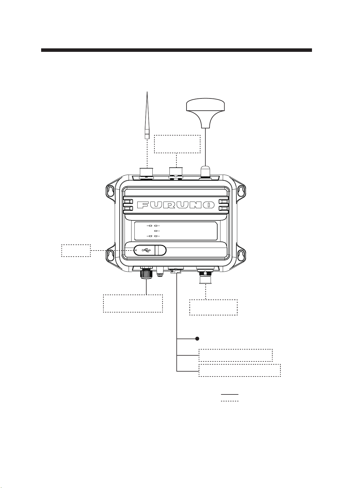
SYSTEM CONFIGURATION
POWER
SILENT
ERROR
RX
TX
Antenna Unit
GPA-017S,
GPA-C01,
or GPA-017*
VHF Antenna
CX4-3/FEC
AIS Transponder FA-70
(Built in VHF Splitter)
PC
NMEA2000 Sensor
or External Display
VHF
Radiotelephone
: Standard supply
: Optional or local supply
NAV Equipment
or Sensor
Ship’s Mains 12-24 VDC
NAV Equipment or Sensor
Contact Switch (Silent Switch)
*: Option
vii
Page 10

SYSTEM CONFIGURATION
This page is intentionally left blank.
viii
Page 11
1. INSTALLATION
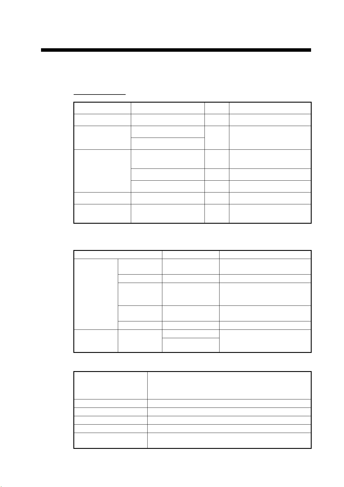
1.1 Equipment List
Standard supply
Name Type Qty Remarks
AIS Transponder FA-70 1 Built in VHF Splitter
Antenna Unit GPA-017S Select
GPA-C01
Installation
Materials
Spare Parts 250VAC 5A 2 Tube Fuses
Accessories FA70/60/40 SW *CD* 1 AIS Setting Tool (CD-ROM
61110000000101 1 PWR/NMEA1/SILENT
NPD-MM1MF1000G02M 1 NMEA2000 Cable
PA425 4 Tapping Screws
one
GPS Antenna
Cable
for PC software*)
*: The CD-ROM for PC software and USB driver is supplied as standard. The folder
structure of the CD-ROM is shown in the table below.
Folder File Remarks
AIS_Setting_
Tool
USBDriver
ForWindows7
DotNetFX40 dotNetFx40_Full_
x86_x64.exe
vcredist_x86 vcredist_x86.exe
Windows
Installer4_5
– AIS_Setting_Tool_
– setup.exe Install file of AIS setting tool
– cdc.cat Install file of USB driver
Windows6.0-
KB958655-v2-
x64.MSU, etc.
Installer.msi
FURUNO_AIS.inf
(required to connect the FA-70
with USB CDC)
PC requirements
OS
CPU Min. 1 GHz
Main memory 32 bit: min. 1 GB, 64 bit: min. 2 GB
Resolution 1280 720 or better
Language pack English
USB communication USB CDC (Communication Device Class)
Microsoft
Microsoft
Microsoft
USB2.0 / Type A-Micro B cable
®
Windows® 7 (32 bit / 64 bit),
®
Windows® 10 (64 bit),
®
Windows® 11 (64 bit)
1-1
Page 12
1. INSTALLATION
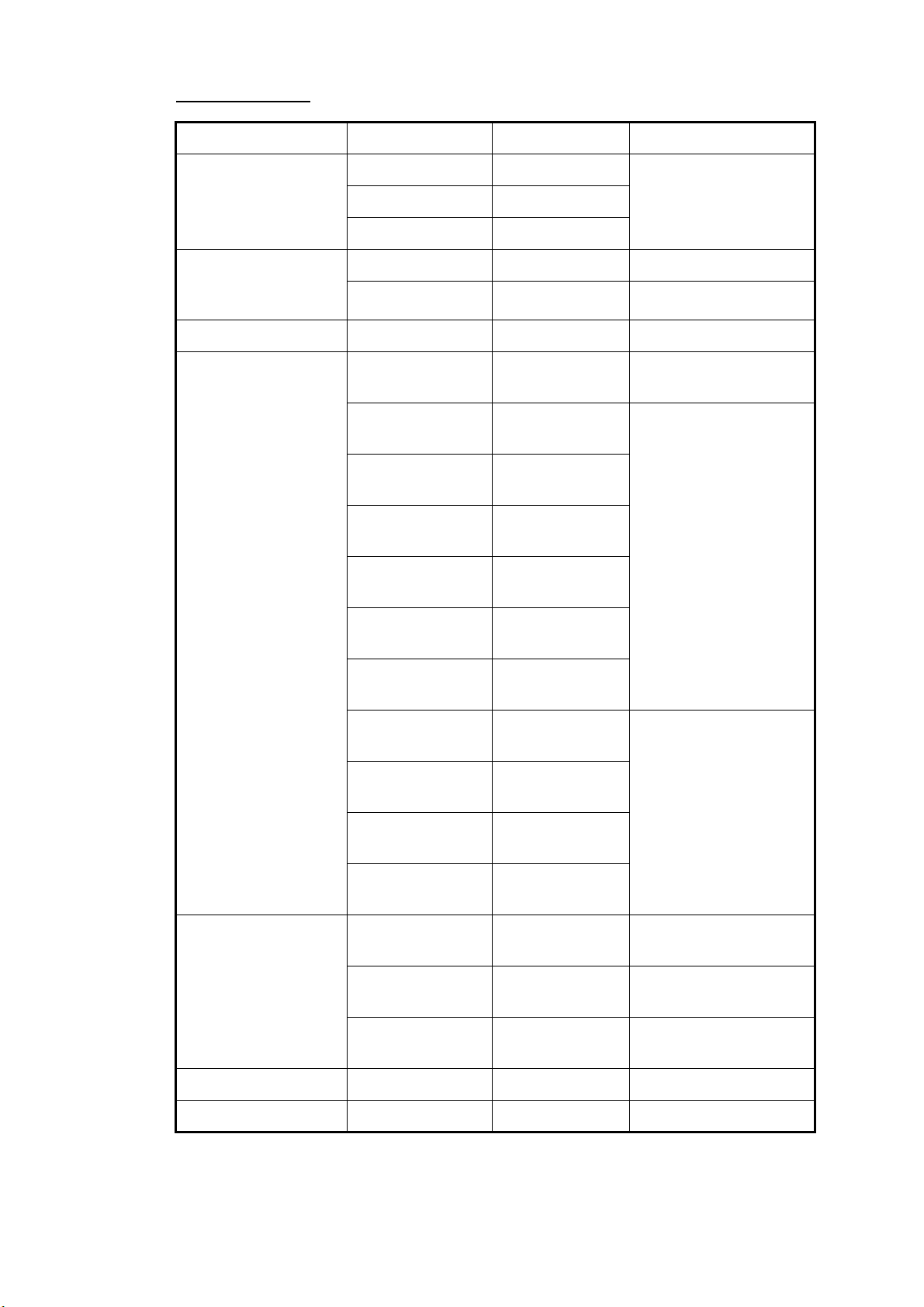
Optional supply
Antenna Unit GPA-017 - GPS antenna
Name Type Code No. Remarks
GPA-017S -
GPA-C01 -
AC/DC Power Supply
Unit
Ferrite Core OP86-11 001-594-450 For PR-241
Cable Assembly TNC-PS/PS-3D-
PR-240 -
PR-241 -
001-173-110-10 For GPA-017S, TNC-
L15M-R
FRU-NMEAPMMFF-010
FRU-NMEAPMMFF-020
FRU-NMEAPMMFF-060
FRU-NMEA-PFF010
FRU-NMEA-PFF020
FRU-NMEA-PFF060
001-533-060 Max. 6 m
001-533-070
001-533-080
001-507-010
001-507-030
001-507-040
TNC (15 m)
MJ-A6SPF0003020C
MJ-A6SPF0003050C
MJ-A6SPF0003100C
MJ-A6SPF0003150C
Antenna Cable
Assembly
Mast Mounting Kit CP20-01111 004-365-780 For GPS antenna
Antenna CX4-3/FEC 001-474-340
CP20-02700
(30M)
CP20-02710
(50M)
CP20-02720
(40M)
000-154-029-10 Max. 15 m
000-154-054-10
000-168-924-10
000-159-643-10
004-381-160 For GPA-017S (30 m),
8D-FB-CV*30M*
004-381-170 For GPA-017S (50 m),
8D-FB-CV*50M*
001-207-990 For GPA-017S (40 m),
8D-FB-CV*40M*
1-2
Page 13
1. INSTALLATION
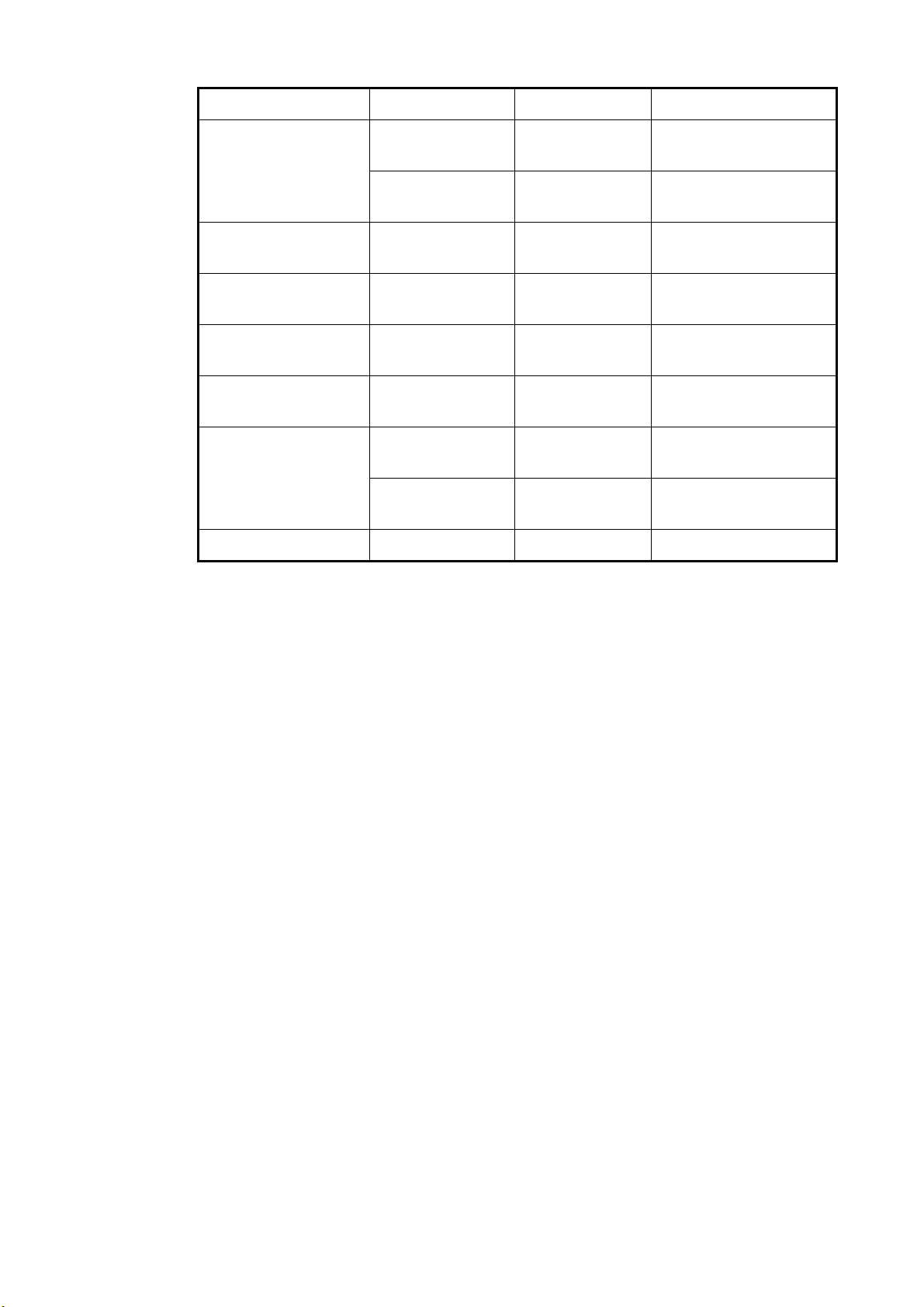
Name Type Code No. Remarks
Antenna Fixing
Bracket
Right Angle Mounting
Base
L-Angle Mounting
Base
Handrail Mounting
Base
Micro T-Connector FRU-
Termination Resistor
(Micro)
In-Line Terminator FRU-0505-FF-IS 001-077-830-10
N173F/FEC 001-474-350 For CX4-3/FEC (φ49-
N174F/FEC 001-494-890 For CX4-3/FEC (φ30-
NO.13-QA330 001-111-910-10 For GPS antenna
NO.13-QA310 001-111-900-10 For GPS antenna
NO.13-RC5160 001-111-920-10 For GPS antenna
001-507-050
MM1MF1MF1001
FRUMM1000000001
FRUMF000000001
001-507-070
001-507-060
90)
61)
1-3
Page 14
1. INSTALLATION
•
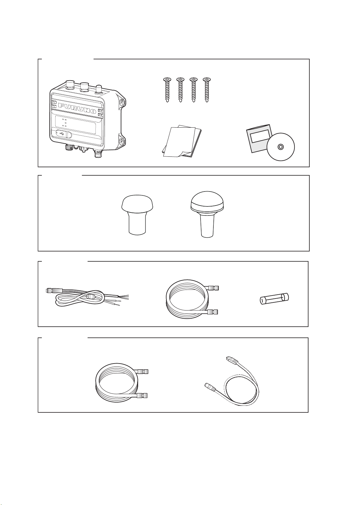
AIS Transponder (1 pcs)
•
Antenna Unit (1 pcs)
AIS Transponder
• Tapping screws (4 pcs)
Antenna Unit
• Spare tube fuse
(5A, 2 pcs)
• Documents (1 set)
Cable assembly
• PWR/NMEA1/SILENT cable (1 pcs): 2 m
• AIS Setting Tool (1 pcs)
• NMEA2000 cable (1 pcs): 2 m
GPA-017S GPA-C01
• USB (standard-A - micro-B) cable: max. 2 m
Local supplies
• 5D-2V cable
1.2 Included Items and Local Supplies
or
1-4
Page 15
1.3 Required Tools and Materials
1
3
4
2
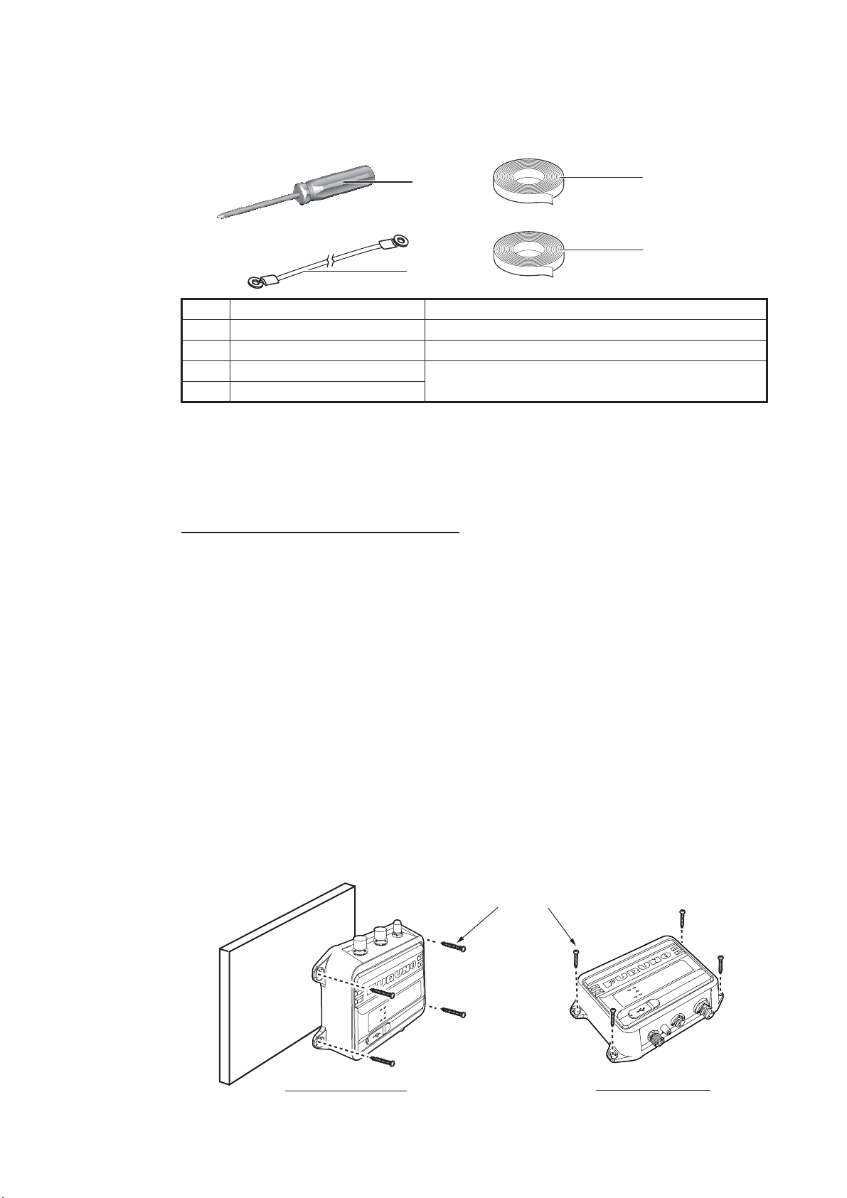
Desktop mounting
Bulkhead mounting
Tapping screws
The following tools should be prepared in advance for this installation.
No. Name Remarks
1 Phillips-head screwdriver #3, for mounting the chassis
2 Ground wire IV-1.25sq
3 Self-vulcanizing tape For waterproofing the junction of connectors
4 Vinyl tape*
*: For cosmetic purposes, black color vinyl tape (cable color) is recommended.
1. INSTALLATION
1.4 AIS Transponder FA-70
Mounting considerations, mounting
The FA-70 can be mounted on a desktop or on a bulkhead. When selecting a mounting location, keep in mind the following points:
• Keep the unit out of direct sunlight.
• The temperature and humidity should be moderate and stable.
• Locate the unit away from exhaust pipes and vents.
• The mounting location should be well ventilated.
• Mount the unit where shock and vibration are minimal.
• Keep the unit away from electromagnetic field-generating equipment such as motors and generators.
• A magnetic compass will be affected if the FA-70 is placed too close to it. Observe
the compass safe distances noted in the safety instructions to prevent disturbance
to the magnetic compass.
Fix the unit to the mounting location with four tapping screws (supplied).
1-5
Page 16
1. INSTALLATION
5050
1515
3030
10
Outer sheath
Cover with heat-shrink
tube or vinyl tape.
Inner
sheath
Braided
shield
Armor
Nut Washer Gasket
Clamp
Core
Core (Adjust
the length.)
Center pin
Fold back the shield. Remove the
shield that hangs over the gasket.
Center pin
(Soldering)
Apply solder to core.
Twist the shield and pass the clamp.
Set the shell to the cable then turn the nut to tighten.
1.5 GPS Antenna
Do not connect the GPS antenna connector to ground.
Short circuit can result.
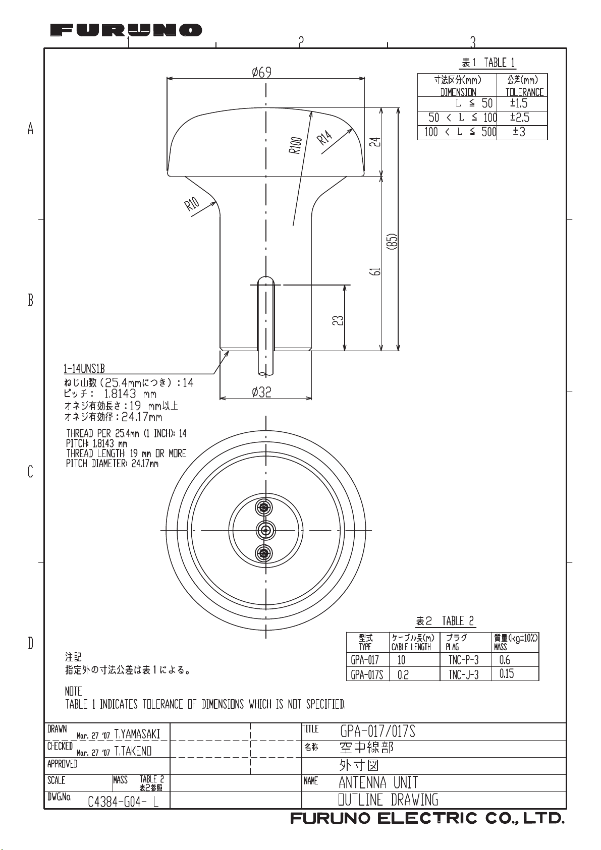
Install the GPS antenna unit referring to the outline drawing at the back of this manual.
When selecting a mounting location for the antenna, keep the following in mind:
• Select a location out of the radar and inmarsat beams. The radar beam will obstruct
or prevent reception of the GPS satellite signal.
• There should be no interfering object within the line-of-sight to the satellites. Objects
within line-of-sight to a satellite, for example, a mast, may block reception or prolong
acquisition time.
• Mount the antenna unit as high as possible to keep it free of interfering objects and
water spray, which can interrupt reception of GPS satellite signal if the water freezes.
CAUTION
• The location should be well away from a VHF antenna. A VHF antenna emits harmonic waves, which can interfere with the GPS receiver.
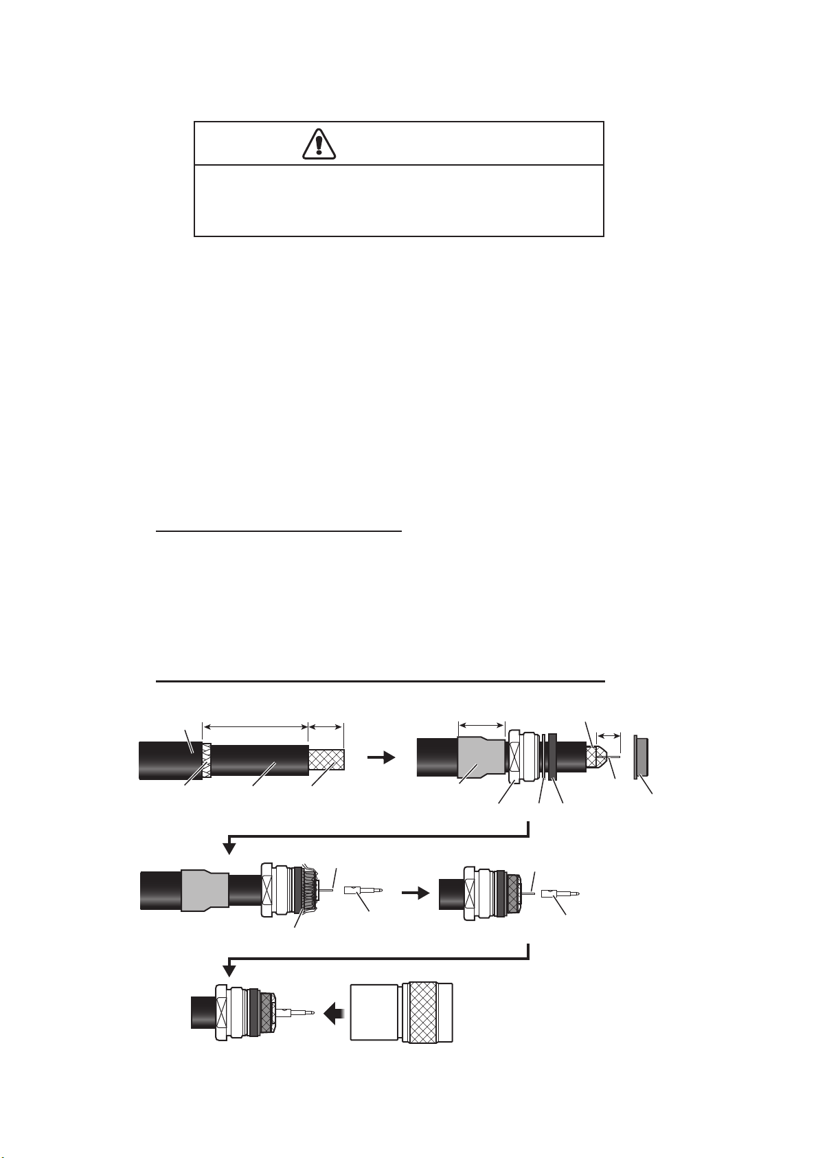
How to extend the antenna cable
Use the cable type RG-10/UY (shipyard supply) to extend the antenna cable.
Note: The length of this cable should be less than 20 m to prevent signal loss. The
coax. coupling cable assy.(type: NJ-TP-3DXV-1, code no. 000-123-809), coaxial connector (N-P-8DFB; supplied), vulcanizing tape and vinyl tape are required. Fabricate
both ends of the cable as shown in the figure below.
How to attach the connector N-P-8DSFA for cable 8D-FB-CV
10
1-6
Page 17
1.6 VHF Antenna (option)
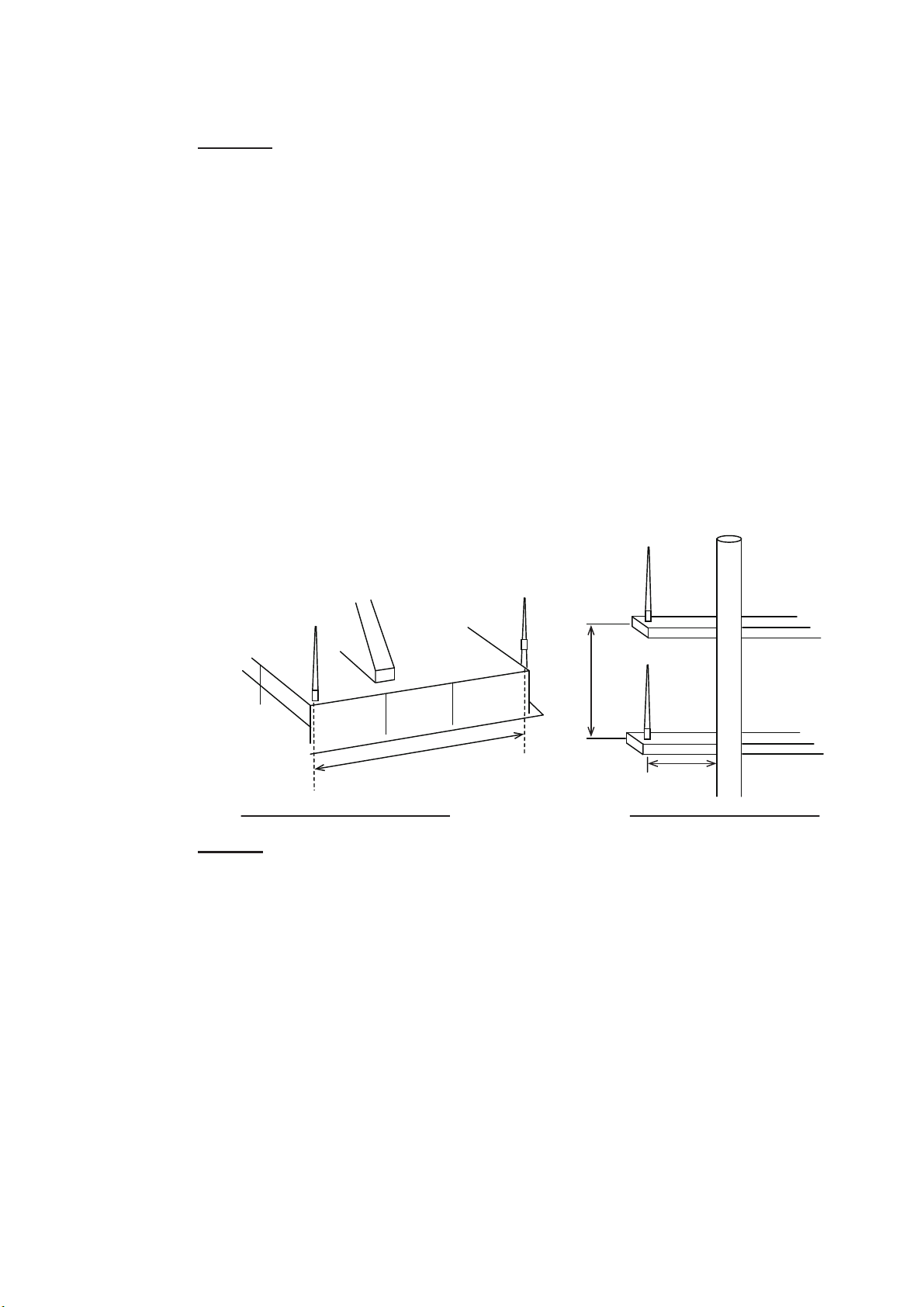
Other VHF antenna
Antenna for AIS
More than 10 m
More than 0.5 m
More than 2.8 m
Horizontal separation distance Vertical separation distance
Location
The location of the VHF antenna should be carefully considered. It may be necessary
to relocate the VHF radiotelephone antenna to minimize interference effects. To minimize interference effects, the following guidelines apply:
• Select a location out of the radar and inmarsat beams. Those beams will obstruct
or prevent reception of the AIS signal.
• The VHF antenna should be placed in an elevated position that is as free as possible with a minimum of 0.5 meters in the horizontal direction from constructions
made of conductive materials. The antenna should not be installed close to any
large vertical obstruction. The objective for the VHF antenna is to see the horizon
freely through 360 degrees.
• There should not be more than one antenna on the same plane. The VHF antenna
should be mounted directly above or below the ship's primary VHF radiotelephone
antenna, with no horizontal separation and with a minimum of 2.8 meters vertical
separation. If it is located on the same plane as other antennas, the distance apart
should be at least 10 meters.
1. INSTALLATION
Cabling
• The cable should be kept as short as possible to minimize signal attenuation. Coaxial cables equal to or better than 5D-2V are recommended.
• All outdoor-installed connectors on coaxial cables should be fitted with preventive
isolation such as vulcanizing tape to protect against water penetration into the antenna cable. Also, apply marine sealant at the antenna base to prevent water intrusion from the screw part of the antenna base.
• Coaxial cables should be installed in separate signal cable channels/tubes and at
least 10 cm away from power supply cables. Crossing of cables should be done at
right angles (90 degrees). The minimum bend radius of the coaxial cable should be
5 times the cable's outer diameter.
When coaxial cable 5D-2V (shipyard supply) is used, attach the coaxial plug M-P-5
(shipyard supply) as shown on the next page.
1-7
Page 18
1. INSTALLATION
Sheath
30 mm
5 mm
2 mm
Conductor
Insulator
Braided shield
Plug assembly
Contact sleeve
Cut conductor
here.
Solder both
sides of hole.
Coupling ring
How to attach the plug M-P-5
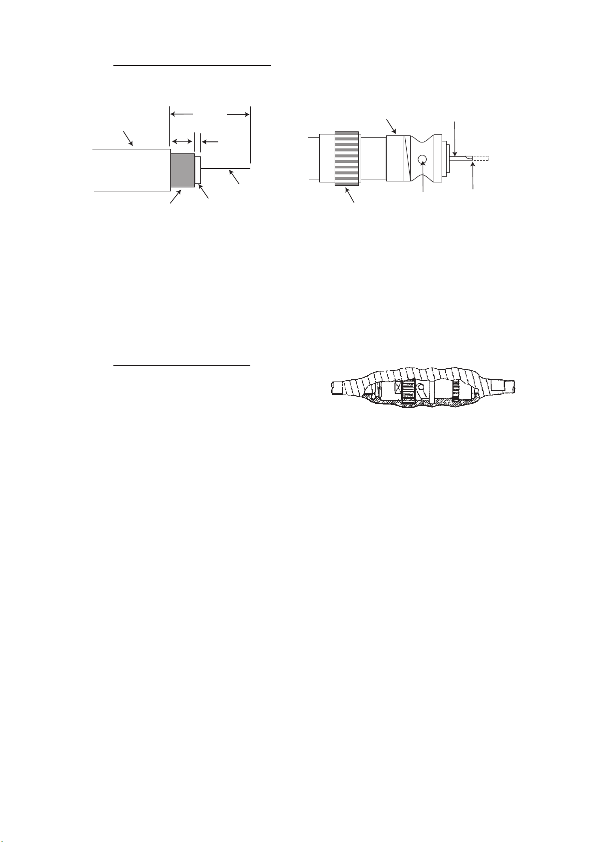
Lay the coaxial cable and attach an M-type plug to the cable as follows.
1. Remove the sheath by 30 mm.
2. Bare 23 mm of the center conductor. Trim braided shield by 5 mm and tin.
3. Slide coupling ring onto cable.
4. Screw the plug assembly on the cable.
5. Solder plug assembly to braided shield through solder holes. Solder contact
sleeve to conductor.
6. Screw coupling ring into plug assembly.
Waterproofing connector
Wrap connector with vulcanizing tape and
then vinyl tape. Bind the tape end with a
cable-tie.
1.7 AC-DC Power Supply (option)
When selecting a mounting location for the unit, keep the following in mind:
• Keep the unit away from areas subject to water splash.
• Locate the unit away from exhaust pipes and vents.
• The mounting location should be well ventilated.
• Mount the unit where shock and vibration are minimal.
• A magnetic compass will be affected if the unit is placed too close to it. Observe the
compass safe distances noted in the safety instructions to prevent disturbance to
the magnetic compass.
Fix the unit with four self-tapping screws (4u16) to a desktop or the deck. It is not necessary to open the cover.
1-8
Page 19
1.8 Wiring
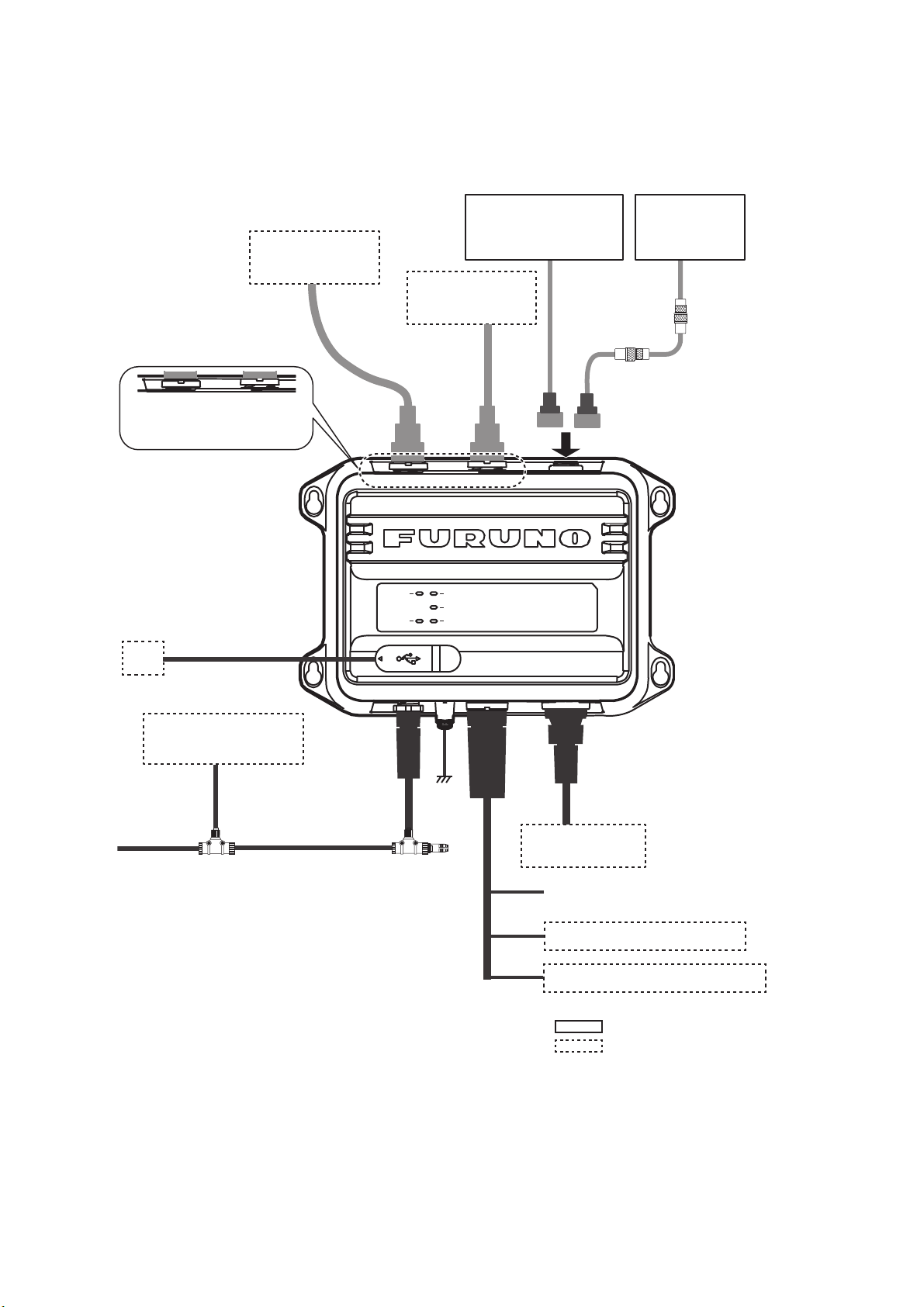
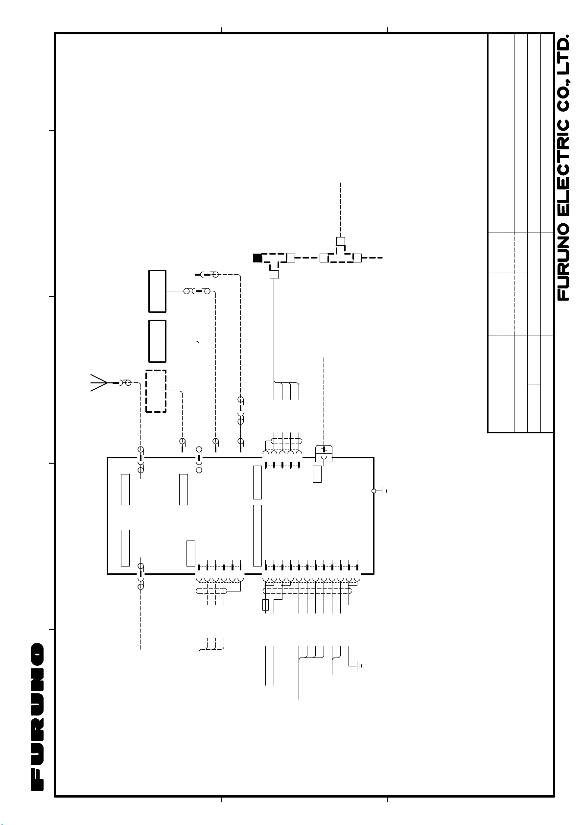
Connect the equipment, referring to the figure below and the interconnection diagram
at the back of this manual.
1. INSTALLATION
VHF ANT VHF RADIO
VHF ANT
VHF RADIO
port
USB Cable, Max 2 m
PC
(Local supply)
VHF Antenna
CX4-3/FEC
5D-2V
port
Antenna Unit
GPA-C01
or optional GPA-017
VHF
Radiotelephone
5D-2V
VHF ANT VHF RADIO GPS ANT
POWER
SILENT
NMEA2000
ERROR
RX
TX
PWR/NMEA1
/SILENT
TNC-P-3,
10 m
or
NMEA2
Antenna Unit
GPA-017S
Option*: 8D-FB-CV,
30/40/50 m
Local supply*:
RG-10/UY, 20 m
or
TNC-PS/PS-3DL15M-R, 15 m
*: NJ-TP-3DXV
(1 m) is required.
NMEA2000 Sensor**
or External Display
NPD-MM1MF
1000G02M, 2 m
Ground
IV-1.25sq
T-connector
**: GP-1871F/1971F, TZT9/14/BB, TZTL12F/15F,
TZT2BB, TZT9F/12F/16F/19F, FI-70, etc.
To connect a monitor that supports NMEA2000
format version 1, set [NMEA2000] - [Format] to
[NMEA2000 V1] (see section 3.1). To connect
multiple monitors where one supports version 1
and the other supports version 2, connect one
of the monitors to the NMEA0183 port.
Note 1: The FA-70 does not have a power switch. Install an external device (power
switchboard, etc.) from which to control its power.
Note 2: Connect the VHF antenna to the “VHF ANT” port, and the VHF radiotelephone
to the “VHF RADIO” port. If the VHF radiotelephone is connected to the “VHF ANT”
port, the VHF radiotelephone and the FA-70 may be damaged.
MJ-A6SPF0003, Max. 15 m
(Option)
NAV Equipment
or Sensor
Ship’s Mains 12-24 VDC
NAV Equipment or Sensor
Contact Switch (Silent Switch)
: Standard supply
: Optional or local supply
1-9
Page 20
1. INSTALLATION
FA-70
TZTL12F/15F, TZT2BB,
TZT9F/12F/16F/19F
FA-70 and PC
USB
FA-70
NMEA2000
FA-70 and NavNet
PC
15 VDC
Terminator
How to waterproof the connector for VHF antenna and VHF radiotelephone
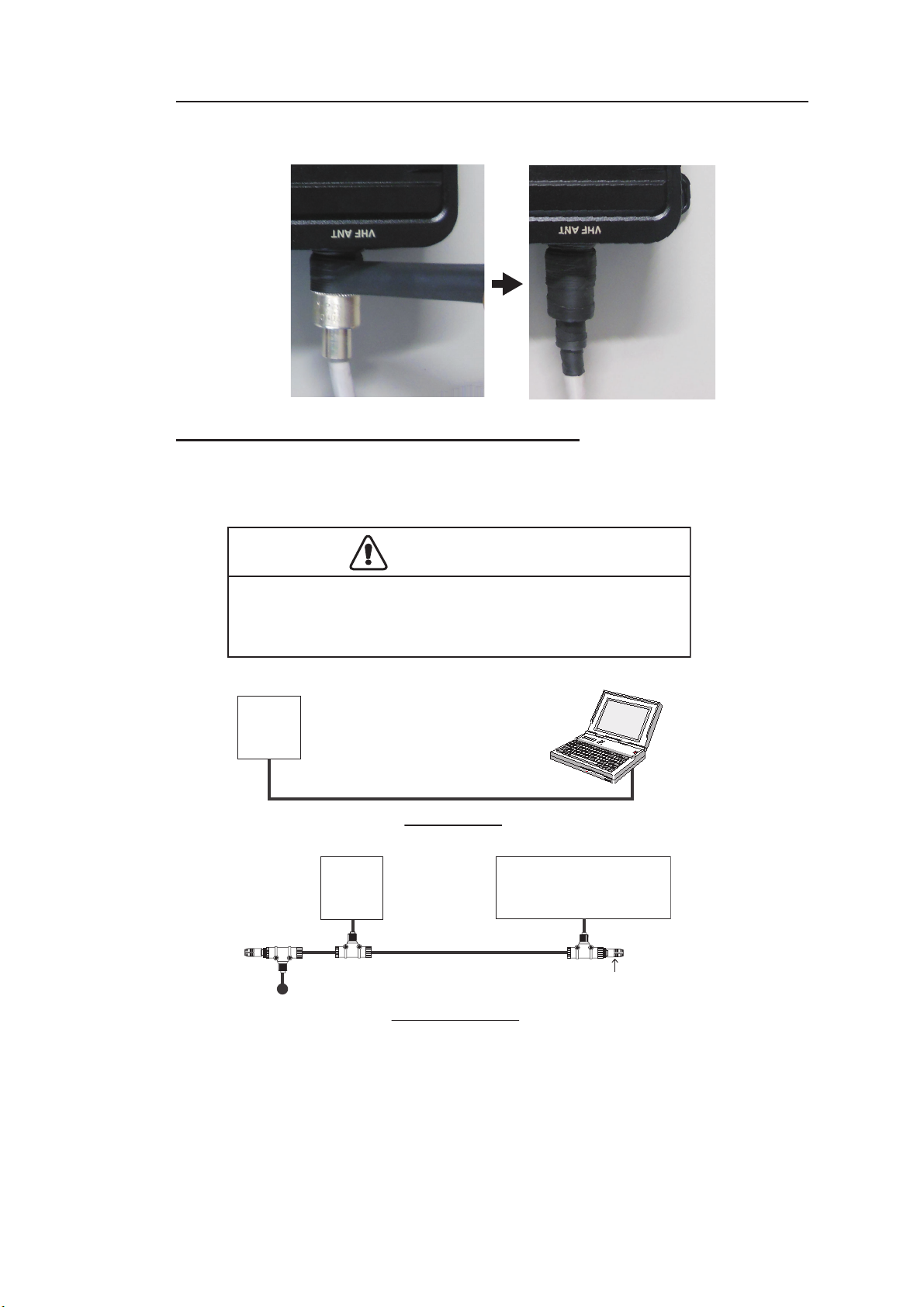
Wrap the connector for VHF antenna and VHF radiotelephone with vulcanizing tape.
Connection with the PC and NavNet TZtouch2/3
The FA-70 may be connected to a PC or TZTL12F/TZTL15F/TZT2BB/TZT9F/
TZT12F/TZT16F/TZT19F. See the figure below for connection examples.
CAUTION
PC connected by USB is only powered by a battery.
Short circuit can result if the PC is connected to ground.
1-10
Page 21

2. SHIP INFORMATION INPUT
You must set the ship static information after the installation of the equipment. The FA70 is set up from the PC or external display (TZTL12F*/15F*/TZT2BB* or TZT9F/12F/
16F/19F). When setting from the PC, install the USB driver and PC software (see sections 2.1 and 2.2). When setting from the external display, open the home screen, and
then select [Settings] - [Initial Setup] - [NETWORK SENSOR SETUP] - [FA-70] in order to display the menus.
*: The software version 07.01 or later is required.
2.1 How to Install the Driver
The CD-ROM for PC software and USB driver is supplied as standard.
Note 1: Install the driver with administration rights.
®
Note 2: In the case of Microsoft
“Driver” file is already installed. If you need to re-install this file, install this file in [Device Manager].
Windows® 10 and Microsoft® Windows® 11, the
Note 3: “Microsoft.NET Framework 4(86 or 64)” is installed at the time of the AIS
Setting Tool installation.
The following instructions are for Windows
1. Turn the FA-70 on.
2. Connect the USB cable between the FA-70 and the PC.
3. Set the supplied CD-ROM in the CD drive.
4. Click the [Start] button and then click [Control Panel].
5. Click [Device Manager].
6. Enter the administrator password and then click [Yes].
7. Double-click [Other devices] – [VIRTUAL COM PORT] in order.
8. Click the [General] tab and then click [Update Driver…].
9. Click [Browse my computer for driver software].
10. Select the [USBDriverForWindows7] folder in the CD-ROM.
11. Click [Install this driver software anyway] to install the driver. After the installation,
[FURUNO AIS (COMxx)] is displayed in [Ports (COM & LPT)] of [Device Manager].
12. Remove the CD-ROM from the CD drive.
®
7.
2-1
Page 22
2. SHIP INFORMATION INPUT
2.2 How to Install the AIS Setting Tool
Note: Install the AIS setting tool with administration rights.
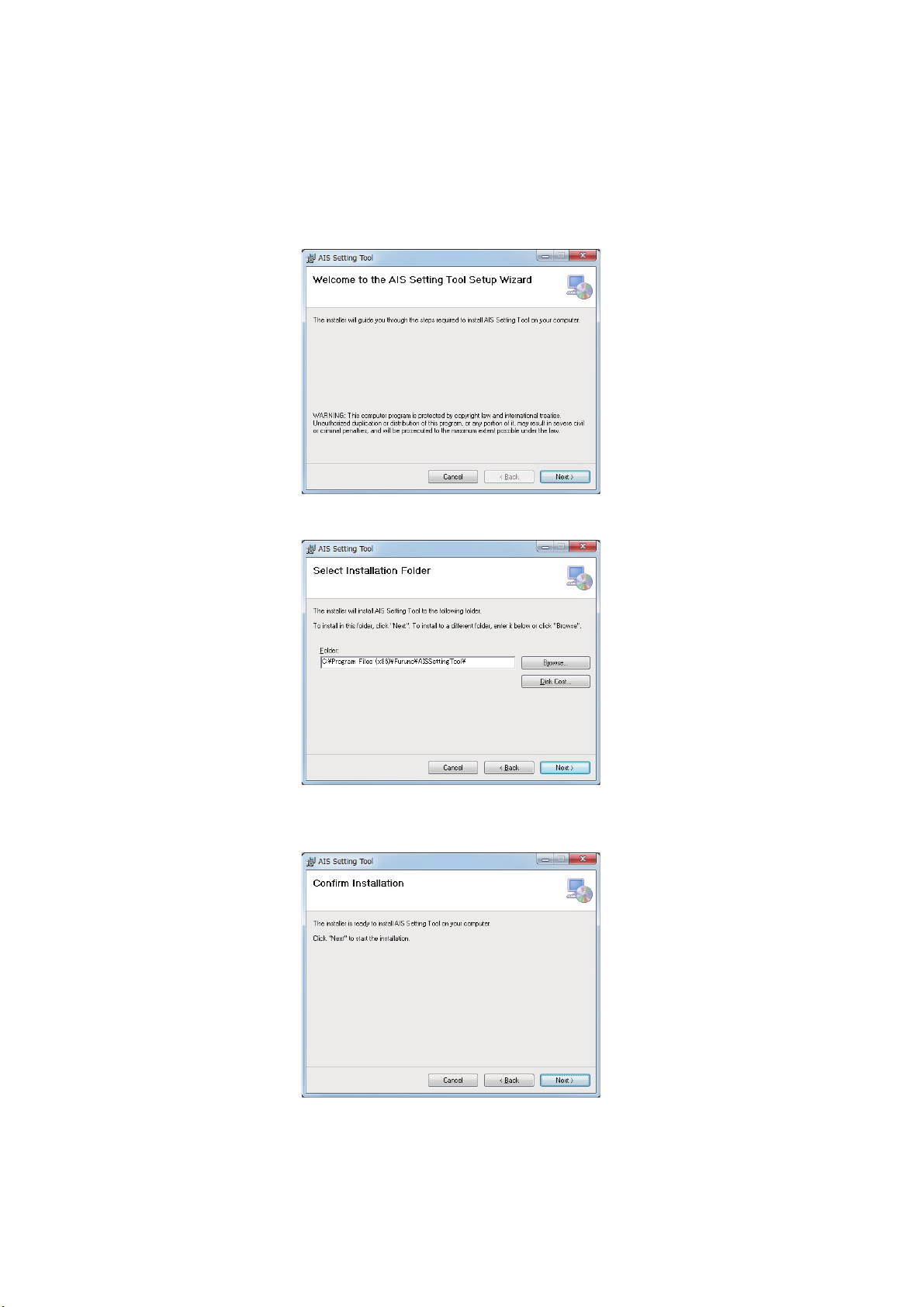
1. Set the supplied CD-ROM in the CD drive.
2. Click [AIS_Setting_Tool].
3. Click [setup.exe].
4. Click [Next].
5. Click [Next]. To change the installation folder, click [Browse] and select the folder
before clicking [Next].
2-2
Page 23
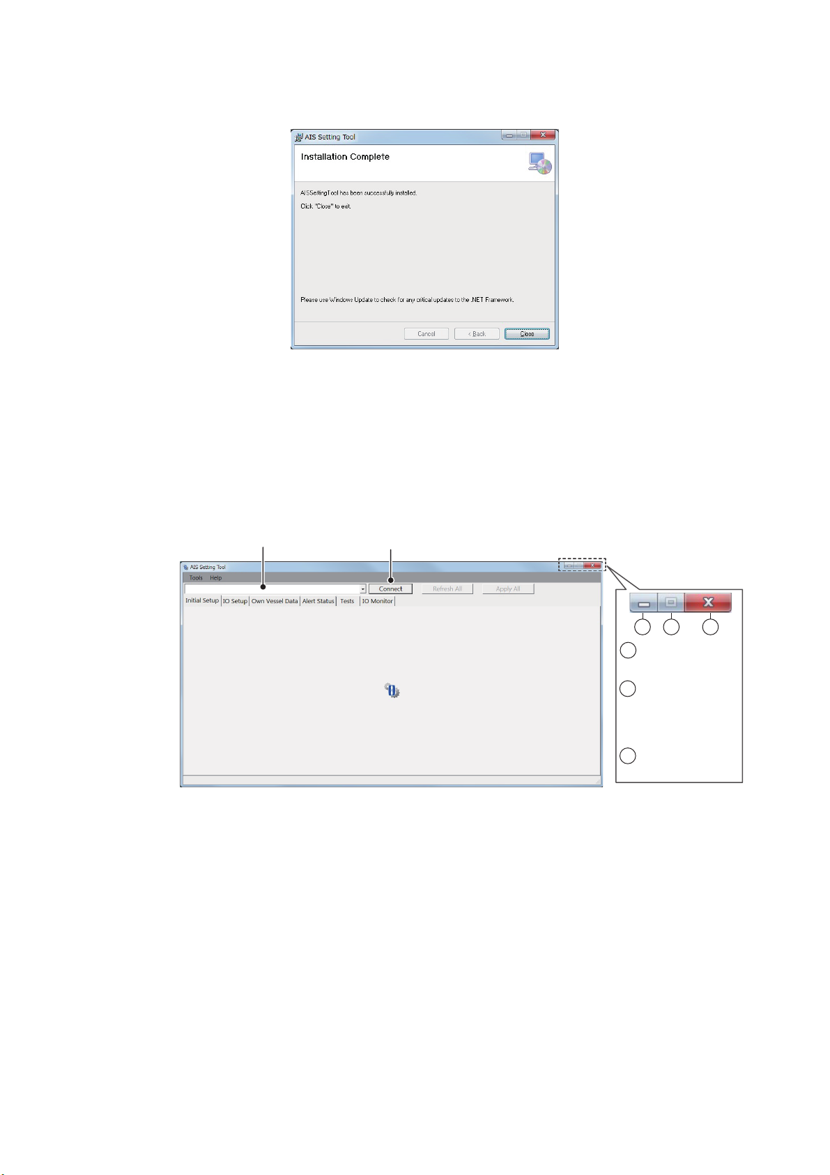
2. SHIP INFORMATION INPUT
3
1
2
1
: Minimize the
window.
2
: Maximize the
window.
(Operation is
not available.)
3
: Close the
window.
Select the COM port to connect.
Connect/Disconnect
6. Click [Next] to start the installation. When the installation is completed, the dialog
box shown below appears.
7. Click [Close] to finish. The shortcut icon for [AIS_Setting_Tool.exe] is created on
your desktop.
8. Remove the CD-ROM from the CD drive.
2.3 How to Start and Quit the AIS Setting Tool
1. Double-click the shortcut icon for [AIS_Setting_Tool.exe].
2. Click the down-allow button at the top left of the screen, and then select the COM
port to connect.
3. Click [Connect].
4. To quit the software, click [Disconnect], and then click the close button (x) at the
upper right-hand corner of the screen.
2-3
Page 24
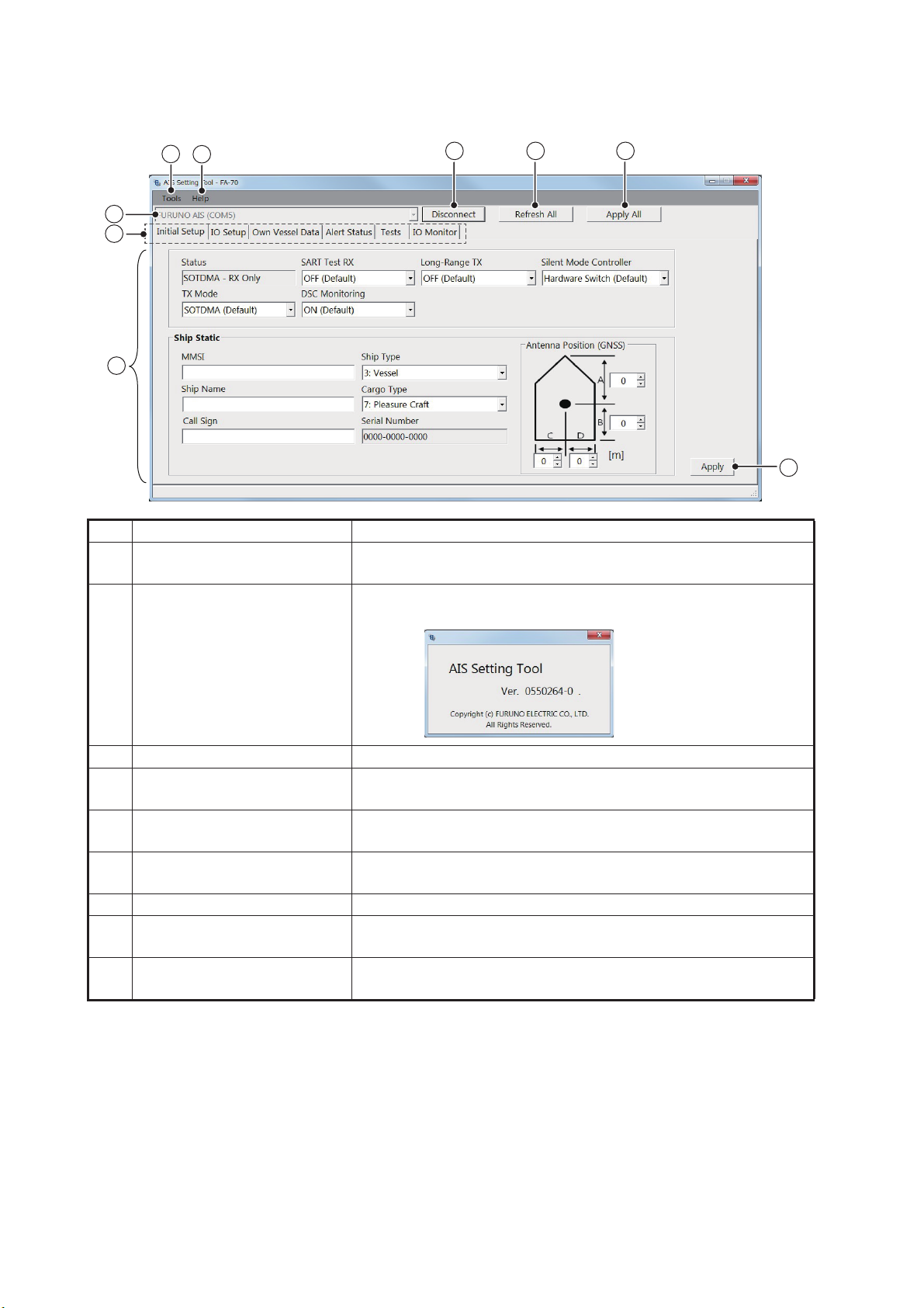
2. SHIP INFORMATION INPUT
1
2
4 5 6
7
8
9
3
1
xx
xx denotes minor
modifications.
2.4 Overview of the AIS Setting Tool
No. Name Description
1 [Tools] • [Disconnect]: Disconnects from the FA-70.
• [Screenshot…]: Takes a screenshot.
2 [Help] • [Usage Considerations]: Shows the precautions for use.
• [About]: Shows the program version number.
3 Port selection Select the COM port to connect.
4 [Connect]/[Disconnect] • [Connect]: Connects to the FA-70.
• [Disconnect]: Disconnects from the FA-70.
5 [Refresh All] Obtains the latest data from the FA-70, and then updates all
settings of all menu tabs.
6 [Apply All] Saves all settings in all tab pages, and then transmits the data
to the FA-70.
7 Menu tab Opens each menu.
8 Setting/Display area Shows the setting values, menu options, status, test results,
and other according to the selected menu.
9 [Apply] Saves all settings in the current tab page, and then transmits
the data to the FA-70.
2-4
Page 25
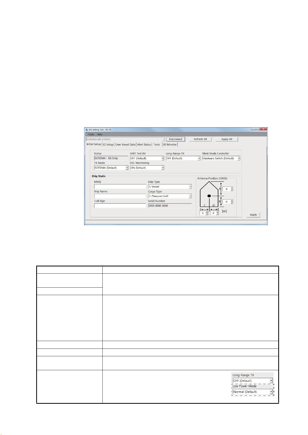
2.5 Initial Setup
[Status] ([AIS Status] on the external display), [Serial Number]: Display only.
You can set up the TX/RX mode, own ship's static information (MMSI, ship's name,
call sign, antenna position and type of ship), and silent mode from the [Initial Setup]
menu. You must set the ship static information.
In the United States of America, it is a violation of the rules of the Federal Communications Commission to input an MMSI that has not been properly assigned to the end
user or to otherwise input any inaccurate data in this device. The MMSI and Static
Data must be entered only by a FURUNO dealer or other appropriately qualified installer of marine communications equipment on board vessels.
For other locations, check your local regulations for details regarding MMSI and static
data input.
2. SHIP INFORMATION INPUT
[Initial Setup] menu for PC
Most of the menu items are the same between the PC and external display. For details, see "MENU TREE" on page AP-1.
Menu item Description
[AIS Status] (for the external display)
[Status] (for the PC)
[TX Mode] Select the transmission mode from [SOTDMA] or [CSTDMA].
[SART Test RX] Select whether to receive an AIS SART test message.
[DSC Monitoring] Select whether to receive a DSC message.
[Long-Range TX] Select whether to transmit a long-range AIS broadcast message. This
[Low Power Mode] When selecting [8: Tanker(s)] in the [Ship Type]
Shows the status for transmission and reception of AIS.
[SOTDMA]: Self-organized time division multiple access (This is the default mode setting.)
[CSTDMA]: Carrier sense time division multiple access (Transmission
interval for CSTDMA is longer than SOTDMA.)
When changing the transmission mode, the confirmation message appears. Click [Yes], and then click [Apply] to restart the FA-70.
menu is displayed when [TX Mode] is set to [SOTDMA].
menu, the [Low Power Mode] menu (see righthand figure) appears on the screen. When docking
the tanker, select [Low Power (1W)] to reduce
transmission power to 1W.
2-5
Page 26
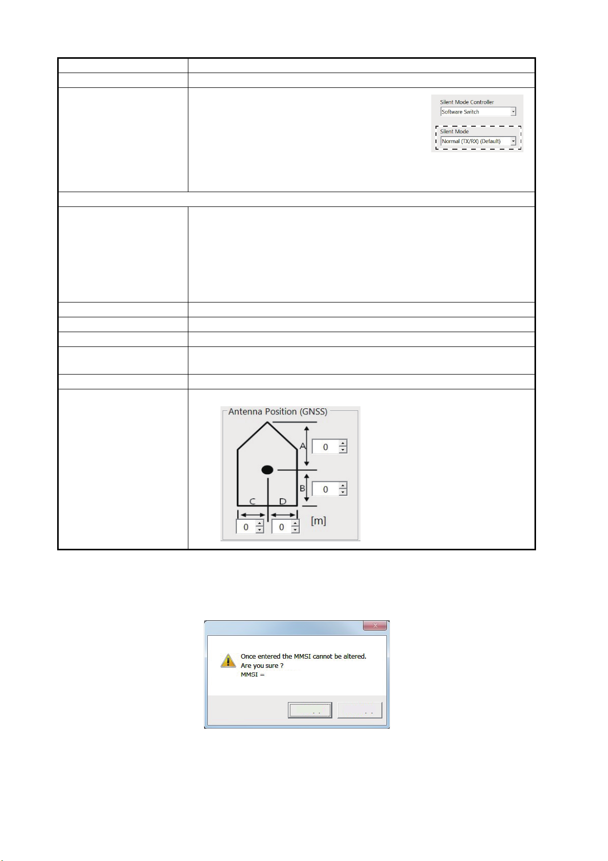
2. SHIP INFORMATION INPUT
XXXXXXXXX
Yes No
Menu item Description
[Silent Mode Controller] Select the silent mode controller from hardware or software.
[Silent Mode] When selecting [Software Switch] in the [Silent
Mode Controller] menu, the [Silent Mode] menu
(see right-hand figure) appears on the screen.
Select the FA-70 function from [Normal (TX/RX)]
or [RX Only].
[Normal (TX/RX)]: The FA-70 transmits and receives.
[RX Only]: The FA-70 receives only.
[Ship Static]
[MMSI] Enter the ship’s MMSI (nine digits). The available MMSI numbers are
displayed at the bottom of the screen.
Note 1: When the ship’s MMSI has already been set, the number is only
displayed.
Note 2: You can enter the MMSI only once. If it becomes necessary to
change the MMSI, contact your dealer.
Note 3: When the MMSI is not set, you can not transmit the data.
[Ship Name] Enter the ship's name, using up to 20 alphanumeric characters.
[Call Sign] Enter the call sign, using seven alphanumeric characters.
[Ship Type] Select the ship type.
[Cargo Type] Select the cargo type. Available options depend on the setting of [Ship
Type].
[Serial Number] Shows the serial number for the equipment.
[Antenna Position] Set the antenna position referring to the following figure.
A: Distance from bow to GPS
antenna position
(setting range: 0 to 511 m)
B: Distance from stern to GPS
antenna position
(setting range: 0 to 511 m)
C: Distance from port to GPS
antenna position
(setting range: 0 to 63 m)
D: Distance from starboard to
GPS antenna position
(setting range: 0 to 63 m)
For the PC, click [Apply] or [Apply All] to confirm the settings.
Note: If you entered the MMSI, the following message appears when clicking [Apply]
or [Apply All].
2-6
Click [Yes] to save the settings, [No] to cancel the settings.
For the external display, the same message appears when entering the MMSI. Select
[Yes] to save the settings, [No] to cancel the settings. When selecting [Yes], the same
message appears again. Select [Yes] again.
Page 27
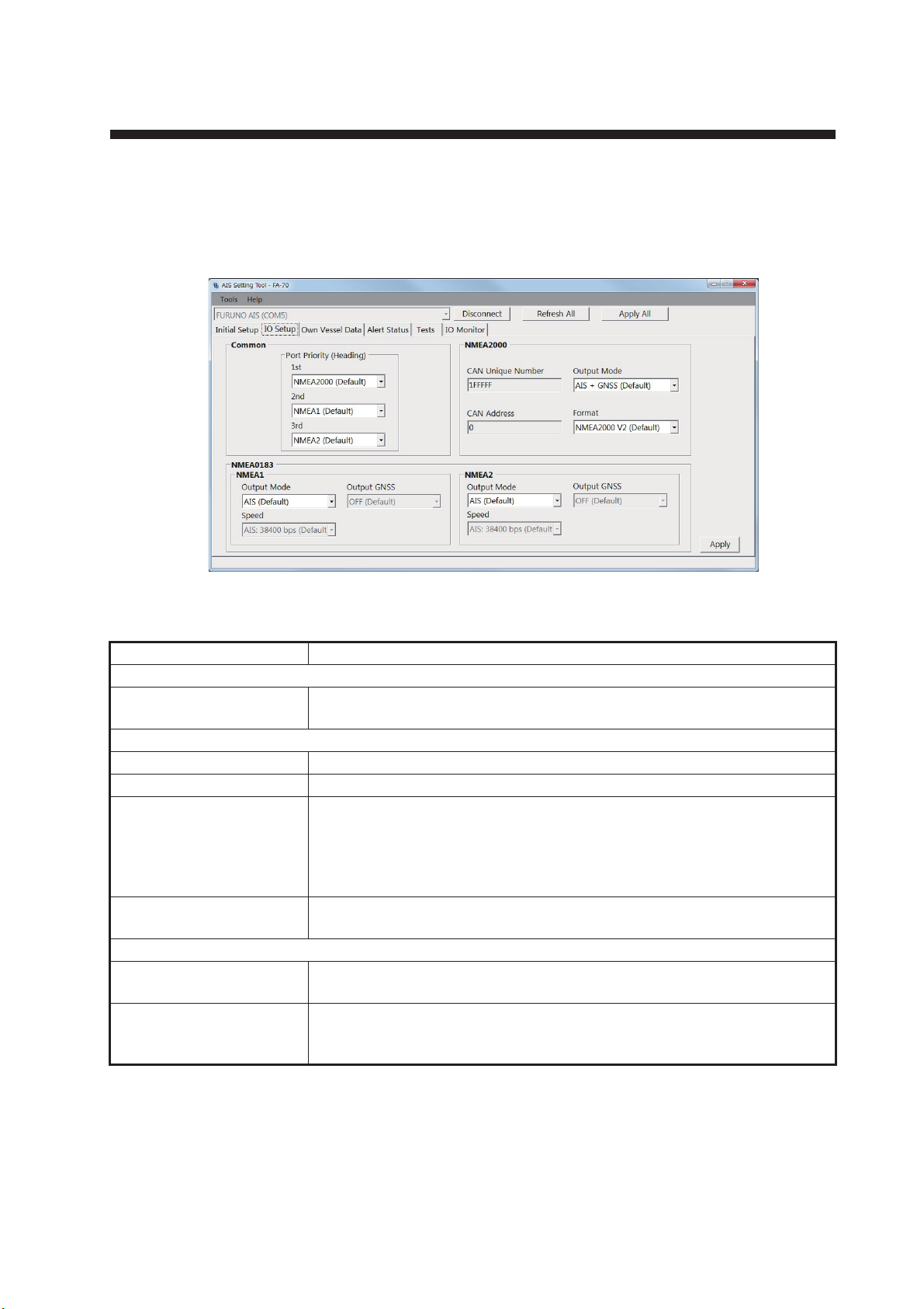
3. SETTINGS AND STATUS
3.1 IO setup (input/output port)
You can change the input/output settings from the [IO Setup] menu.
[CAN Unique Number], [CAN Address]: Display only.
[IO Setup] menu for PC
Menu item Description
[Common]
[Port Priority (Heading)]
[1st], [2nd], [3rd]
[NMEA2000]
[CAN Unique Number] Shows the CAN unique number.
[CAN Address] Shows the CAN address.
[Output Mode] Select the output mode among [OFF], [AIS], [GNSS], or [AIS + GNSS].
[Format] Select the output PGN format version from [NMEA2000 V2] or
[NMEA0183]
[NMEA1 Output Mode],
[NMEA2 Output Mode]
[NMEA1 Speed],
[NMEA2 Speed]
Set the input port priority for heading data.
[OFF]: Does not output AIS or GNSS data.
[AIS]: Outputs AIS data.
[GNSS]: Outputs GNSS data.
[AIS + GNSS]: Outputs both AIS and GNSS data.
[NMEA2000 V1].
Select the output mode among [OFF], [AIS], [GNSS], or [AIS + GNSS].
When selecting [OFF] or [GNSS] in the [NMEA1/NMEA2 Output Mode]
menu, select the baudrate for NMEA1/NMEA2 from [AIS: 38400 bps] or
[Sensor: 4800 bps].
3-1
Page 28
3. SETTINGS AND STATUS
Menu item Description
[NMEA1 Output GNSS],
[NMEA2 Output GNSS]
When selecting [GNSS] or [AIS + GNSS] in the [NMEA1/NMEA2 Output
Mode] menu, select the output GNSS sentence for NMEA1/NMEA2
among [OFF], [GGA + VTG (Sentences)], [GLL + VTG (Sentences)] or
[RMC (Sentence)].
[OFF]: Does not output GGA, VTG, GLL or RMC sentence.
[GGA + VTG (Sentences)]: Outputs GGA and VTG sentences.
[GLL + VTG (Sentences)]: Outputs GLL and VTG sentences.
[RMC (Sentence)]: Outputs RMC sentence.
For the PC, click [Apply] or [Apply All] to confirm the settings.
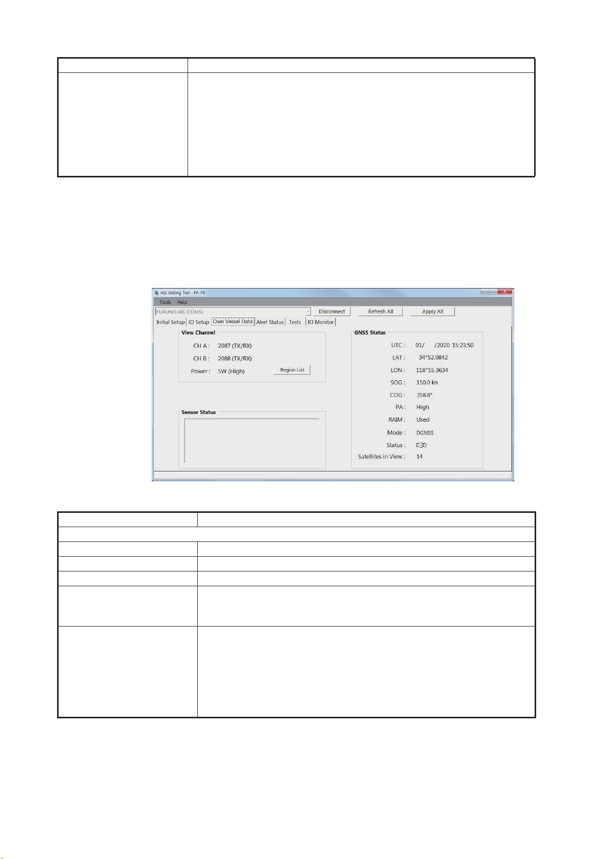
3.2 Own Vessel Data Screen
The [Own Vessel Data] screen shows AIS channel, sensor status, and GNSS status.
JAN
Internal DGNSS in Use (Message 17)
Internal SOG/COG in Use
Heading Valid
Channel Management Parameters Changed
[Own Vessel Data] screen for PC
Menu item Description
[View Channel]
[CH A] Shows the channel number and TX/RX mode for channel A.
[CH B] Shows the channel number and TX/RX mode for channel B.
[Power] Shows the transmission power.
[Region List] (for the PC) Shows the channel management information of local sea areas.
To take a screenshot, click [Screenshot] at the bottom right of the
screen.
[Sensor Status] Shows the information about the sensors connected to the FA-70.
• Internal DGNSS in Use: DGNSS currently in use.
• Internal GNSS in Use: GNSS currently in use.
• Internal SOG/COG in Use: SOG/COG currently in use.
• Heading Valid: Heading data is valid.
• Channel Management Parameters Changed (for the PC): Channel
parameters have been changed.
3-2
Page 29
Menu item Description
[GNSS Status] (for the PC) Shows the GNSS information.
• [UTC]: Universal Time Coordinated
• [LAT]: Latitude
• [LON]: Longitude
• [SOG]: Speed over ground
• [COG]: Course over ground
• [PA]: Positioning accuracy
• [RAIM] (Receiver autonomous integrity monitoring): Whether to use
RAIM or not.
• [Mode]: Positioning mode
• [Status]: Positioning status
• [Satellites in View]: The number of satellites in view.
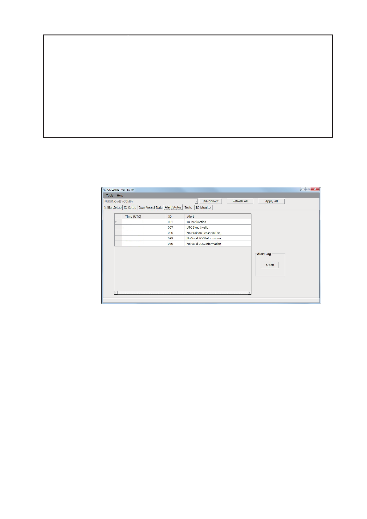
3.3 Alert Status
The [Alert Status] screen shows the alerts currently occurred.
3. SETTINGS AND STATUS
01/JAN/2020 18:30
01/JAN/2020 18:31
01/JAN/2020 18:32
01/JAN/2020 18:35
01/JAN/2020 18:37
[Alert Status] screen for PC
• [Time [UTC]]: Shows the time and date when the alert occurred.
• [ID]: Shows the alert number.
• [Alert]: Shows the alert message*.
*: For the external display, select the alert ID to display the alert message on the bottom of the screen.
3-3
Page 30
3. SETTINGS AND STATUS
Display area of receiving data
Character
count
For the PC, click [Open] of [Alert Log] to show the alerts that occurred in the past (max.
20 alerts).
• [Time [UTC]]: Shows the time and date when the alert occurred.
• [Alert]: Shows the alert message.
• [Reason]: Shows the reason why the alert occurred.
01/JAN/2020 18:30
01/JAN/2020 18:31
01/JAN/2020 18:32
01/JAN/2020 18:35
01/JAN/2020 18:37
Click [Screenshot] to take a screenshot.
For the alert lists, see page AP-4.
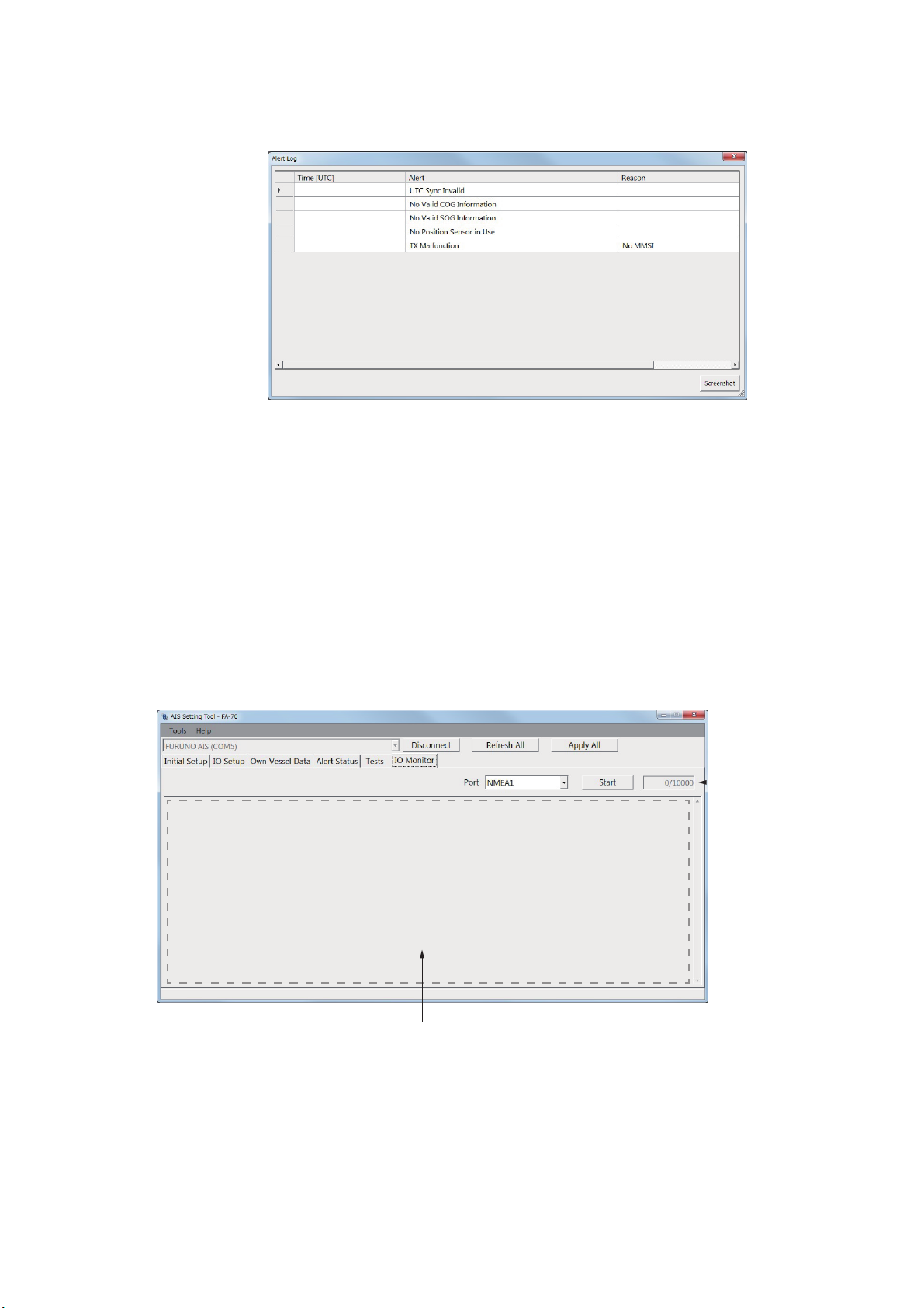
3.4 IO Monitor
The data input from each port can be monitored.
Note: This menu appears only on the PC.
3-4
• [Port]: Select the port that displays the received data.
• [Start]: Click to start the receiving data display. The display shows a maximum of
10,000 characters. The [Start] button changes to the [Stop] button.
• [Stop]: Click to stop the receiving data display. The [Stop] button changes to the
[Start] button.
Page 31
4. MAINTENANCE
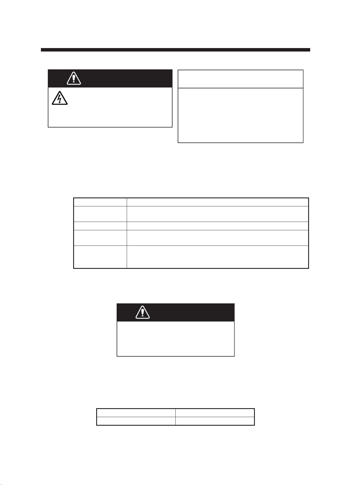
WARNING
ELECTRICAL SHOCK HAZARD
Do not open the equipment.
Only qualified personnel can
work inside the equipment.
NOTICE
Do not apply paint, anti-corrosive sealant
or contact spray to coating or plastic
parts of the equipment.
Those items contain organic solvents that
can damage coating and plastic parts,
especially plastic connectors.
4.1 Maintenance
Regular maintenance helps good performance. Check the items listed below monthly
to keep your equipment in good working order.
Wiring Check that each cable and wire are securely fastened.
Ground Check grounding for rust. Clean if necessary.
Antenna Check antenna and its cabling for damage.
Cabinet Dust and dirt should be removed from the cabinet with a soft, dry
Item Check point
Refasten if necessary.
Replace if necessary.
cloth. Do not use chemical-based cleaners; they can remove paint
and markings.
4.2 Replacement of Fuse
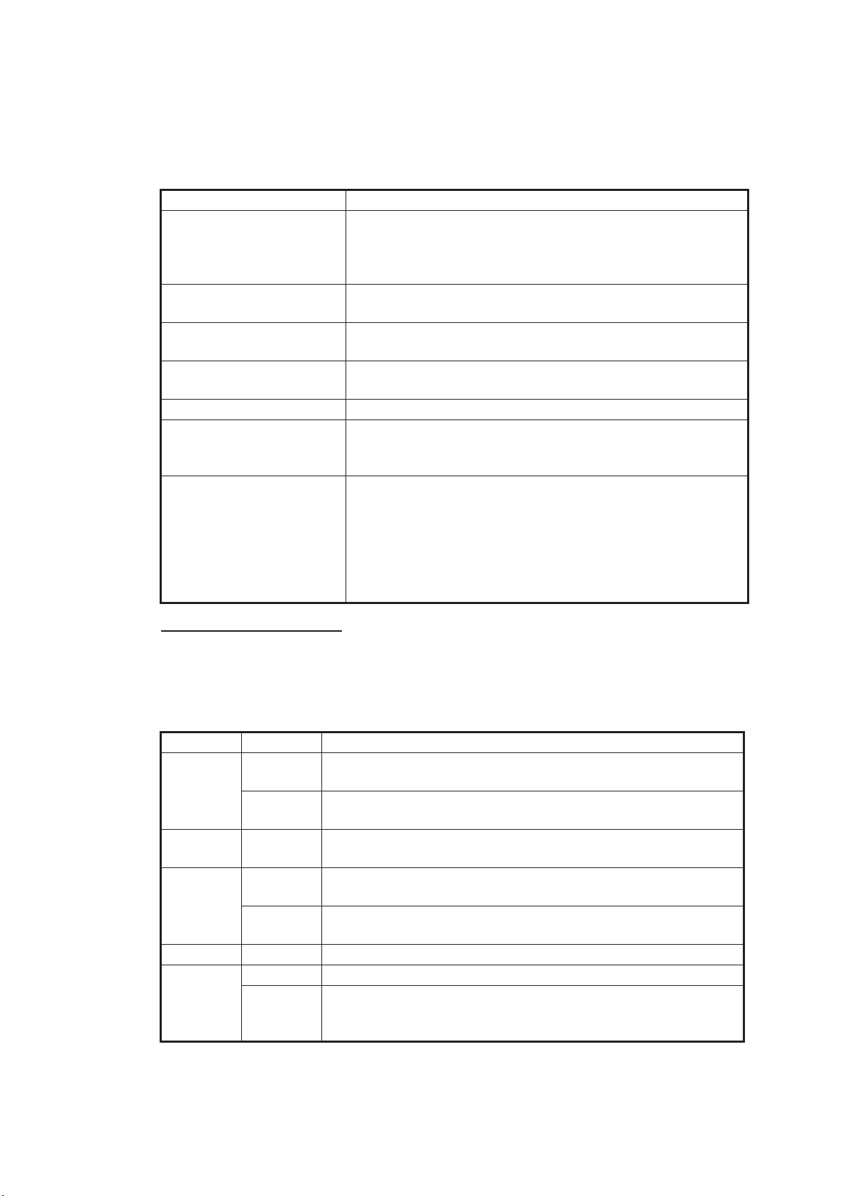
Use the correct fuse.
Use of a wrong fuse can cause fire or
serious damage to the equipment.
The fuse (5A) in the cable protects the equipment from overcurrent and equipment
fault. If the unit cannot be powered, that is, the POWER LED does not light, the fuse
may have blown. If this happens, turn off the power to the FA-70, and check the fuse.
If the fuse has blown, find out the reason before replacing it. If it blows again after replacement, contact your dealer for advice.
Tube Fuse 250VAC 5A
Name Type
WARNING
4-1
Page 32
4. MAINTENANCE
4.3 Troubleshooting
The troubleshooting table below provides typical operating problems and the means
to restore normal operation. If you cannot restore normal operation, do not open the
cover of the FA-70; there are no user serviceable parts inside the transponder.
Symptom Remedy
Cannot turn on the power. • Check the cable between the transponder and power for
Cannot transmit/receive. • Check that the VHF antenna cable is firmly connected.
The message is sent to a
wrong ship.
No position data. • Check the GPS antenna.
ERROR LED lights in red. Contact your dealer.
ERROR LED lights in or-
ange.
Cannot start the AIS Setting Tool, or cannot connect the PC to the
transponder.
damage.
• Check the power supply.
• Check the fuse.
• Check the VHF antenna and its cabling for damage.
Confirm the MMSI.
• Check the GPS antenna cable and its connectors.
• Check that the GPS antenna is correctly connected.
• Check that the VHF antenna is correctly connected.
• Confirm the MMSI.
• Check the USB cable between the transponder and the
PC for damage.
• Do the following:
1) Quit the AIS Setting Tool.
2) Disconnect the USB cable from the PC, and then con-
nect the cable again.
3) Start the AIS Setting Tool.
AIS Transponder FA-70
The FA-70 has no power switch. Power is fed from the ship's switchboard, and a power switch on the switchboard turns the FA-70 on or off.
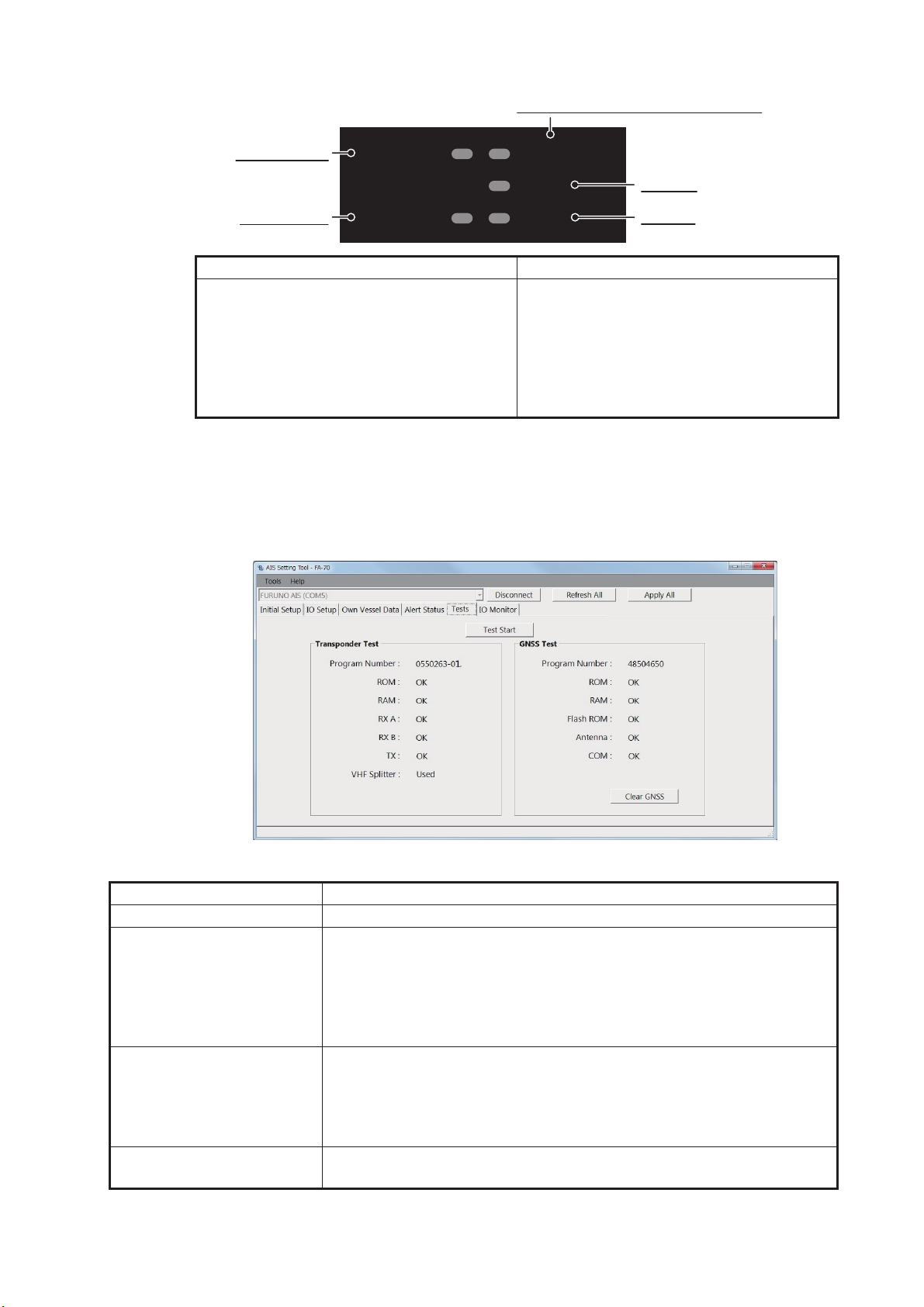
The table below shows the function for each LED.
LED Color Meaning
POWER Green When the power is on, the POWER LED lights in green for
CSTDMA mode.
Blue When the power is on, the POWER LED lights in blue for
SOTDMA mode.
SILENT Blue The SILENT LED lights in blue when the silent mode is set to
on.
ERROR Red The ERROR LED lights in red when equipment error (TX, RX,
ROM, or RAM) is found.
Orange The ERROR LED lights in orange when the equipment is not
installed correctly.
RX Green The RX LED lights in green for 50 msec when receiving.
TX Green The TX LED lights in green for 200 msec when transmitting.
Orange • The TX LED blinks in orange when continuous transmission
is not possible (TX time out).
• The TX LED lights in orange when the MMSI is not set.
4-2
Page 33
4. MAINTENANCE
ERROR LED (See the table below.)
POWER LED
SILENT LED
Red Orange
• Memory error
• RX1/2 PLL unlock error
• TX PLL unlock error
• TX power error
4.4 Diagnostics
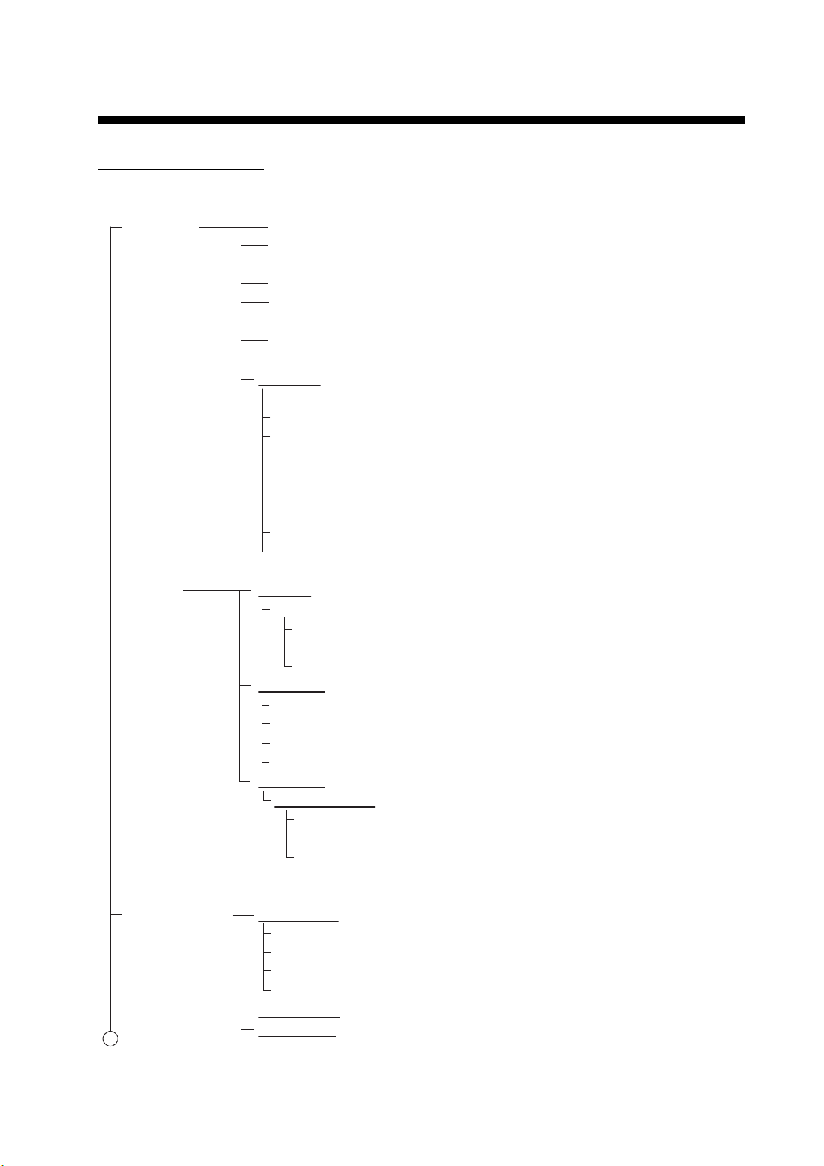
The FA-70 provides diagnostic tests to check the transponder unit for proper operation.
POWER
SILENT
--
--
ERROR
-
RX
TX
• GPS antenna short
• Lost position
• VSWR error
• Temperature error
• Power amplifier voltage error
• MMSI not registered
• Noise level error (CSTDMA mode only)
RX LED
TX LED
xx
xx
[Tests] screen for PC
Menu item Description
[Test Start] (for the PC) Click to start the test.
[Transponder Test] The program version number appears on the first line. The RAM,
ROM, two RX channels (A and B) and TX are checked for proper operation, and the results are displayed as "OK" or "NG" (No Good). For
any NG, contact your dealer for advice. When the VHF splitter board
is connected, "Used" appears, not connected, "Unused" appears on
the last line.
[GNSS Test] The program version number appears on the first line. The ROM,
RAM, Flash ROM, the connection with antenna (including power line)
and COM (communication) are checked for proper operation, and the
results are displayed as [OK] or [NG] (No Good). For any NG, contact
your dealer for advice.
[Clear GNSS] (for the PC) Click to initialize the internal GNSS core. The confirmation message
"Clear GNSS. Are you sure?" appears. Click [Yes] to initialize.
4-3
Page 34

4. MAINTENANCE
This page is intentionally left blank.
4-4
Page 35
APPX. 1 MENU TREE
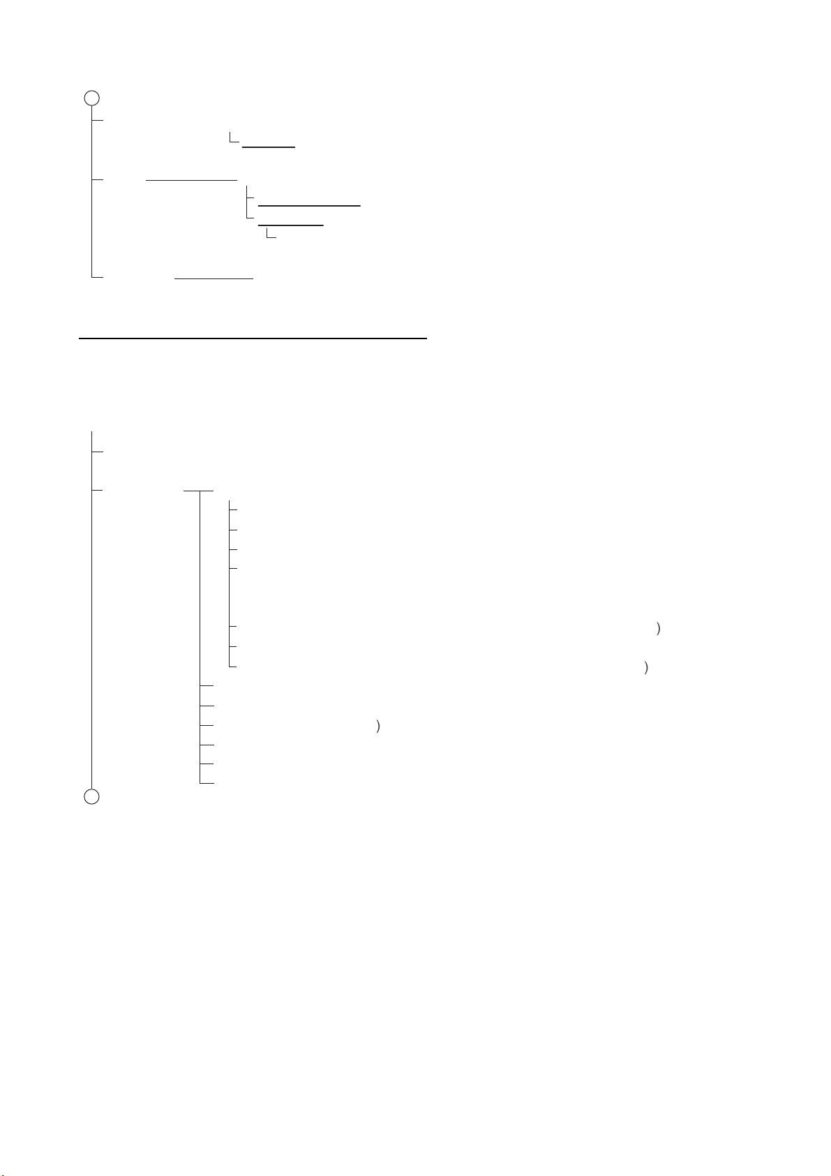
Initial Setup Status (Shows the status for transmission and reception of AIS.)
TX Mode (SOTDMA, CSTDMA)
SART Test RX (OFF, ON)
DSC Monitoring (OFF, ON)
Long-Range TX
*1
(OFF, ON)
Low Power Mode
*2
(Normal, Low Power (1W))
Silent Mode Controller (Hardware Switch, Software Switch)
Silent Mode
*3
(Normal (TX/RX), RX Only)
Ship Static
MMSI (Enter the MMSI number.)
Ship Name (Enter the ship’s name.)
Call Sign (Enter the call sign.)
Ship Type (0: Not Available or No ship, 1: Reserved for Future Use, 2: WIG,
3: Vessel, 4: HSC, 5: Special Craft, 6: Passenger Ships, 7: Cargo Ships,
8: Tanker(s), 9: Other Types of Ship)
Cargo Type (Options are differ depending on the setting in [Ship Type].)
Serial Number (Shows the serial number for the equipment.)
Antenna Position (GNSS) (A/B: 0 to 511 m; 0 m, C/D: 0 to 63 m; 0 m)
IO Setup Common
Port Priority (Heading)
1st (NMEA2000, NMEA1, NMEA2)
2nd (NMEA2000, NMEA1, NMEA2)
3rd (NMEA2000, NMEA1, NMEA2)
NMEA2000
CAN Unique Number (Shows the CAN unique number.)
CAN Address (Shows the CAN address.)
Output Mode (OFF, AIS, GNSS, AIS + GNSS)
Format (NMEA2000 V2, NMEA2000 V1)
NMEA0183
NMEA1 / NMEA2
Output Mode (OFF, AIS, GNSS, AIS + GNSS)
Speed (AIS: 38400 bps, Sensor: 4800 bps)
*4
Output GNSS (OFF, GGA + VTG Sentences, GLL + VTG Sentences,
RMC Sentence)
*5
Own Vessel Data View Channel
CH A: (Shows the channel number and TX/RX mode for channel A.)
CH B: (Shows the channel number and TX/RX mode for channel B.)
Power (Shows the transmission power.)
Region List (Shows the channel management information of local sea areas.)
Sensor Status (Shows the sensor information.)
GNSS Status (Shows the GNSS information.)
Bold italic: Default
1
*5
: These options are selectabled when [Output
Mode] is set to [GNSS] or [AIS + GNSS].
*3
: This menu item is displayed when [Silent
Mode Controller] is set to [Software Switch].
*1
: This menu item is displayed when
[TX Mode ] is set to [SOTDMA].
*4
: Fixed to [AIS: 38400 bps] when [Output Mode]
is set to [AIS] or [AIS + GNSS].
*2
: This menu item is displayed when
[Ship Type] is set to [8: Tanker(s)].
AIS Setting Tool (PC)
AP-1
Page 36
APPX. 1 MENU TREE
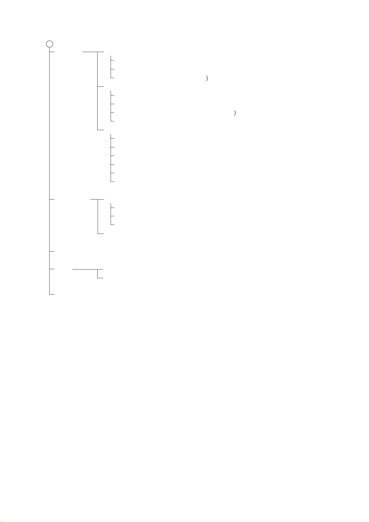
Alert Status (Shows the alerts currently occurred.)
Alert Log (Shows the alerts occurred in the past.)
Tests Test Start (Starts the test.)
Transponder Test (Shows the self test result for the FA-70.)
GNSS Test (Shows the self test result for the internal GNSS core.)
Clear GNSS (Clears the GNSS test result.)
IO Monitor Port (NMEA1, NMEA2, NMEA2000)
1
AIS S
)
c
SI
)
C
)
S
,
)
(
Options are differ depending on the setting in [Ship Type].
)
SS) (A/
m
)
S
)
*2
(
)
S
)
S
e
*3
)
Bold italic: Default
1
Menu
*3
: This menu item is displayed when [Silent
Mode Controller] is set to [Software Switch].
*1
: You can enter the MMSI only once.
After entering the MMSI, only the
number is displayed.
*2
: This menu item is displayed when
[TX Mode ] is set to [SOTDMA].
TZTL12F/15F, TZT2BB, TZT9F/12F/16F/19F
On the home screen, select [Settings] - [Initial Setup] - [NETWORK SENSOR SETUP] - [FA-70]
in order to display the menus.
tatus (Shows the status for transmission and reception of AIS.
nitial Setup
hip Stati
MM
1
Ship Name (Enter the ship’s name.
all Sign (Enter the call sign.
hip Type (0: Not Available or No ship, 1: Reserved for Future Use, 2: WIG,
: Vessel, 4: HSC, 5: Special Craft, 6: Passenger Ships, 7: Cargo Ships
8: Tanker(s), 9: Other Types of Ship
Cargo Type
Serial Number (Shows the serial number for the equipment.
Antenna Position (GN
B: 0 to 511 m;
TX Mode (TDMA, CSTDMA
ART Test RX (FF, ON
DSC Monitoring (OFF,
Long-Range TX
ilent Mode Controller (Hardware Switch, Software Switch
ilent Mod
(Normal (TX/RX) RX Only
FF, ON
m, C/D: 0 to 63 m;
AP-2
Page 37
APPX. 1 MENU TREE
(
)
(
000
)
(
)
(
2000
C
)
C
)
O
SS
(
000 V2
)
0183
)
(
A
)
*1
C)
*2
)
(
A
)
*1
C)
*2
Own Vessel View Channel
Data CH A: (Shows the channel number and TX/RX mode for channel A.)
CH B: (Shows the channel number and TX/RX mode for channel B.)
Power (Shows the transmission power.)
Sensor Status (Shows the sensor information.)
Alert Status (Shows IDs and occurrence times of alerts currently occurred.)
Tests Transponder Test (Shows the self test result for the FA-70.)
GNSS Test (Shows the self test result for the internal GNSS core.)
Refresh Menu (Yes, No)
1
*2
: These options are selectabled when [Output
Mode] is set to [GNSS] or [AIS + GNSS].
*1
: Fixed to [AIS: 38400 bps] when [Output Mode]
is set to [AIS] or [AIS + GNSS].
Setup Port Priority
1st
2nd
3rd
Heading
NMEA2
NMEA1, NMEA2
NMEA2000, NMEA1 NMEA2
NMEA2000, NMEA1,
MEA
Format
AN Unique Number (Shows the CAN unique number.
AN Address (Shows the CAN address.
utput Mode (OFF, AIS, GNSS,AIS + GN
NMEA2
NMEA2000 V1
MEA
NMEA1 Output Mode (OFF,AIS GNSS, AIS + GNSS
NMEA1
NMEA1
peed
IS: 38400 bps, Sensor: 4800 bps
utput GNSS (FF GGA + VTG, GLL + VTG, RM
NMEA2 Output Mode (OFF,AIS GNSS, AIS + GNSS
NMEA2 Speed
NMEA2
utput GNSS (FF GGA + VTG, GLL + VTG, RM
IS: 38400 bps, Sensor: 4800 bps
AP-3
Page 38
APPX. 2 ALERT LISTS
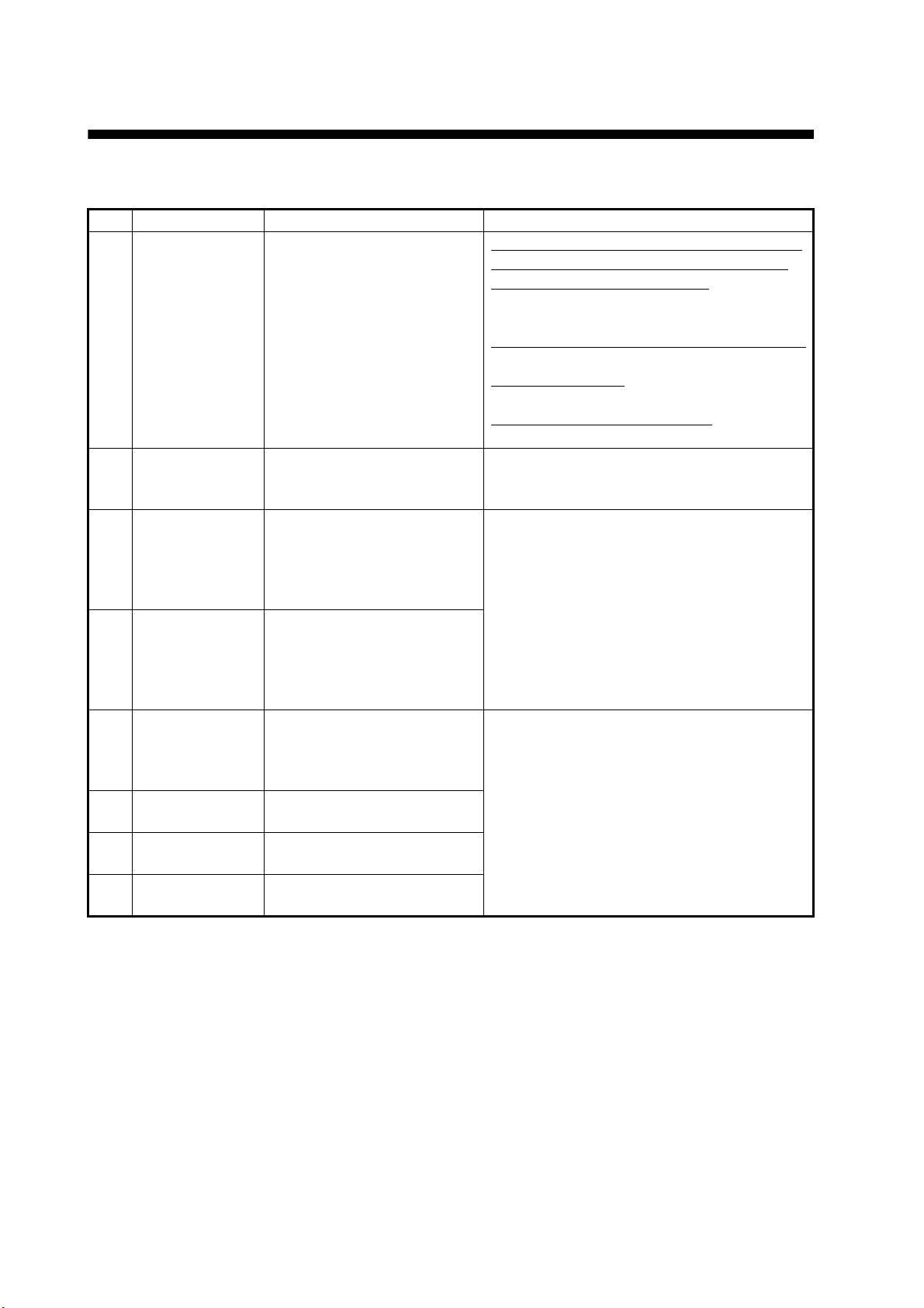
The table below shows the alert ID, text, meaning and remedy for each alert.
ID Text Meaning Remedy
001 TX Malfunction Transmission failure oc-
curred. (The ERROR LED
lights in red or orange.)
002 Antenna VSWR
Exceeds Limit
003 RX Channel 1
Malfunction
004 RX Channel 2
Malfunction
007 UTC Sync Inval-idInternal GPS has no fix.
026 No Position
Sensor in Use
029 No Valid SOG
Information
030 No Valid COG
Information
High VSWR for the AIS antenna detected. (Continued
operation possible.)
RX1 hardware trouble.
Transmission stopped on
corresponding TX channel.
(The ERROR LED lights in
red.)
RX2 hardware trouble.
Transmission stopped on
corresponding TX channel.
(The ERROR LED lights in
red.)
(Continued operation possible using indirect or semaphore synchronization.)
No L/L data. (Continued operation possible.)
Invalid SOG data. (Continued operation possible.)
Invalid COG data. (Continued operation possible.)
Reasons: RF AMP Too Hot, Regulator For
RF AMP Too Hot, VSWR Exceeds Limit,
Current to RF AMP Regulated
Check the VHF antenna and FA-70 connections.
Reason: TX PLL Error, TX Power Abnormal
Contact your dealer.
Reason: No MMSI
Check that the own ship MMSI is set.
Reason: Noise Level Too High
Check noise sources near the antenna.
Check the VHF antenna. If the problem is
not rectified, contact your dealer.
Circuit board may be damaged. Contact
your dealer.
Check the GPS antenna connection. If the
error appears frequently, contact your dealer.
AP-4
Page 39
APPX. 3 NMEA2000/0183 INPUT/OUTPUT DATA
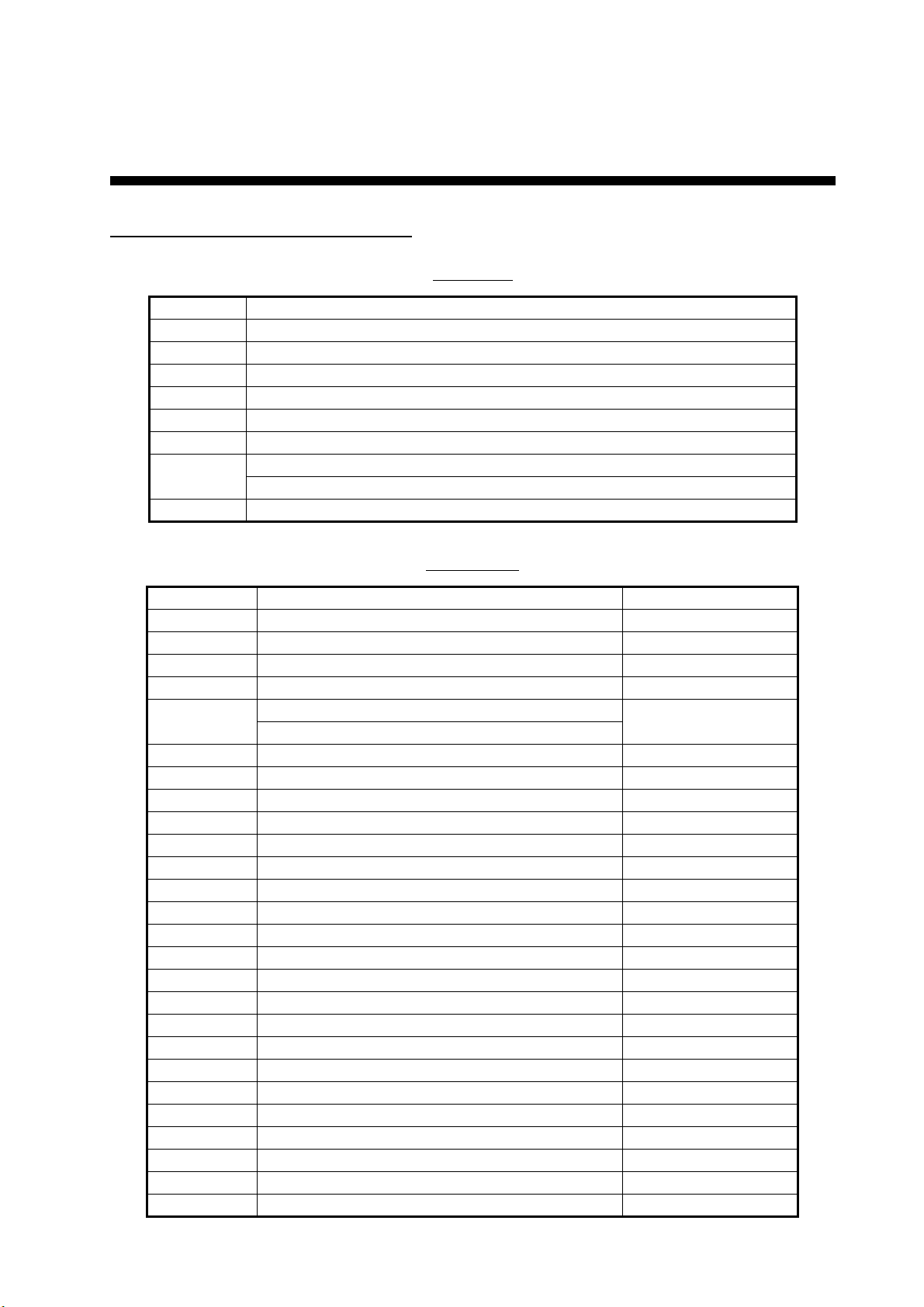
CAN bus (NMEA2000) input/output
Input PGN
PGN Description
059392 ISO Acknowledgment
059904 ISO Request
060160 ISO Transport Protocol, Data Transfer
060416 ISO Transport Protocol, Connection Management - BAM Group Function
060928 ISO Address Claim
065240 ISO Commanded Address
126208 NMEA - Request Group Function
NMEA - Command Group Function
127250 Vessel Heading
Output PGN
PGN Description Output cycle
059392 ISO Acknowledgment
059904 ISO Request
060928 ISO Address Claim
126208 NMEA - Acknowledge Group Function
126464 PGN List - Transmit PGN’s Group Function *2
PGN List - Received PGN’s Group Function
126992 System Time 1,000
126993 Heartbeat 60,000
126996 Product Information *2
126998 Configuration Information *2
127258 Magnetic Variation 1,000
129025 Position, Rapid Update 100
129026 COG & SOG, Rapid Update 250
129029 GNSS Position Data 1,000
129038 AIS Class A Position Report
129039 AIS Class B Position Report
129040 AIS Class B Extended Position Report
129041 AIS Aids to Navigation (AtoN) Report
129540 GNSS Sats in View 1,000
129792 AIS DGNSS Broadcast Binary Message
129793 AIS UTC and Date Report
129794 AIS Class A Static and Voyage Related Data
129795 AIS Addressed Binary Message *3
129796 AIS Acknowledge
129797 AIS Binary Broadcast Message
129798 AIS SAR Aircraft Position Report
129801 AIS Addressed Safety Related Message
*1
(ms)
AP-5
Page 40
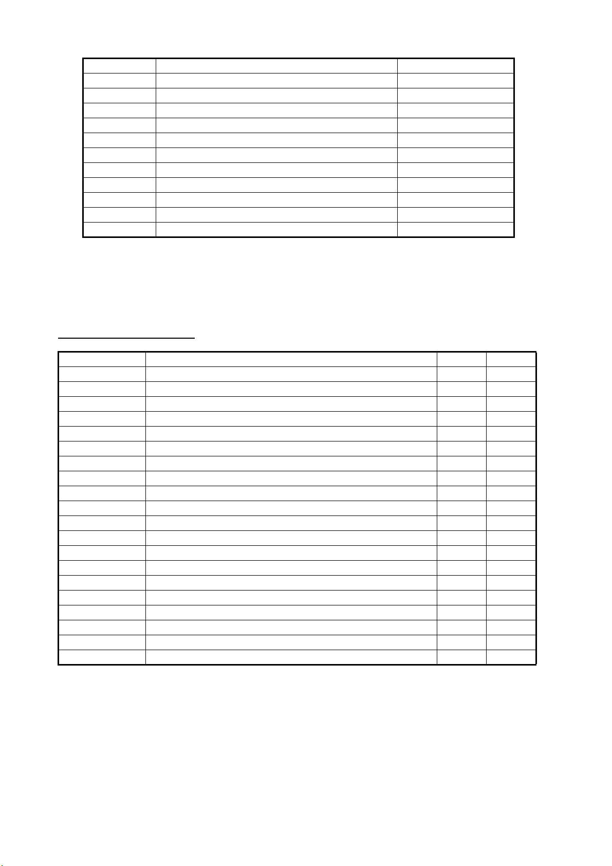
APPX. 3 NMEA2000/0183 INPUT/OUTPUT DATA
PGN Description Output cycle
129802 AIS Safety Related Broadcast Message
129803 AIS Interrogation
129804 AIS Assignment Mode Command *3
129805 AIS Data Link Management Message
129806 AIS Channel Management
129807 AIS Group Assignment
129809 AIS Class B “CS” Static Data Report, Part A
129810 AIS Class B "CS" Static Data Report, Part B
129811 AIS Single Slot Binary Message
129812 AIS Multi Slot Binary Message *3
129813 AIS Long - Range Broadcast Message *3
*1
: Output cycle for an AIS related PGN depends on vessel traffic conditions.
*2
: Outputs when receiving output request.
*3
: SOTDMA mode only
*1
(ms)
NMEA0183 input/output
Sentence Description Input Output
ABM AIS Addressed and Binary Broadcast Acknowledgement *
ABK AIS Addressed and Binary Broadcast Acknowledgement
ACA AIS Regional Channel Assignment Message
ACK Acknowledge Alarm
ACS AIS Channel Management Information Source
AIQ Query Sentence
ALR Set Alarm State
BBM AIS Broadcast Binary Message *
GGA Global Positioning System Fix Data
GLL Geographic Position - Latitude/Longitude
HDT Heading, True
RMC Recommended Minimum Specific GNSS Data
SSD AIS Ship Static Data
THS True Heading and Status
TXT Text Transmission
VDM AIS VHF Data-Link Message
VDO AIS VHF Data-Link Own-Vessel Report
VER Version
VSD AIS Voyage Static Data
VTG Course Over Ground & Ground Speed
*
: SOTDMA mode only
AP-6
Page 41

APPX. 4 RADIO REGULATORY
USA-Federal Communications Commission (FCC)
This device complies with part 15 of the FCC Rules. Operation is subject to the following two conditions:
(1) This device may not cause harmful interference, and
(2) This device must accept any interference received, including interference that may cause undesired
operation. Any changes or modifications not expressly approved by the party responsible for
compliance could void the user's authority to operate the equipment.
Caution: Exposure to Radio Frequency Radiation
• This equipment complies with FCC radiation exposure limits set forth for an uncontrolled environment
and meets the FCC radio frequency (RF) Exposure Guidelines in Supplement C to OET65.
• This equipment should be installed and operated keeping the radiator at least 20 cm or more away
from person's body.
• This device must not be co-located or operating in conjunction with any other antenna or transmitter.
Innovation, Science and Economic Development Canada (ISED)
Caution: Exposure to Radio Frequency Radiation
This equipment complies with ISED radiation exposure limits set forth for an uncontrolled environment
and meets RSS-102 of the ISED radio frequency (RF) Exposure rules. This equipment should be
installed and operated keeping the radiator at least 20 cm or more away from person's body.
Cet équipement est conforme aux limites d'exposition aux rayonnements énoncées pour un
environnement non contr êolé et respecte les règles d'exposition aux fréquences radioélectriques (RF)
CNR-102 de l'ISED. Cet équipement doit etre installé et utilise en gardant une distance de 20 cm ou
plus entre le dispositif rayonnant et le corps.
To reduce potential radio interference to other users, the antenna type and its gain should be so chosen
that the equivalent isotropically radiated power (EIRP) is not more than that required for successful
communication.
INFORMATION
AP-7
Page 42

FURUNO
SPECIFICATIONS OF CLASS B AIS TRANSPONDER
FA-70
1 GENERAL
1.1 Type Class B AIS Transponder
1.2 RX capacity 2250 report/minute, 1 channel
4500 report/minute, 2 channel
1.3 RX system SOTDMA or CSTDMA (user select),
dual wave simultaneous reception
1.4 Synchronous framing UTC direct or UTC indirect (SOTDMA)
UTC direct (CSTDMA)
1.5 Operating mode Autonomous, Assigned, polled/interrogation response
1.6 Frequency switching Automatic
1.7 DSC receiving Time sharing system
1.8 Initialization Within 2 minutes after power-on
1.9 Prevention of abnormal TX Auto-suspended for detecting TX more than 1 second
1.10 Regulations IEC 62287-1/2
2 TRANSMITTER
2.1 Frequency range 156.025 MHz to 162.025 MHz (F1D)
2.2 Output power 5 W or 1W (SOTDMA), 2 W (CSTDMA)
2.3 Modulation GMSK
2.4 Channel interval 25 kHz
2.5 Frequency deviation ±500 Hz
2.6 Spurious emission 9 kHz to 1 GHz, -36 dBm or less
1 GHz to 4 GHz, -30 dBm or less
2.7 Transmission interval
SOTDMA 5 s (SOG>23 kn), 15 s (14<SOG23 kn), 30 s (2<SOG14 kn),
3 min. (SOG2 kn)
CSTDMA 30 s (SOG>2 kn), 3 min. (SOG2 kn)
3 AIS RECEIVER
3.1 Frequency range 156.025 MHz to 162.025 MHz (F1D)
3.2 Oscillator frequency 1st local oscillator: f+ (46.35/58.05 MHz),
2
3.3 Intermediate frequency 1
3.4 Receiving method Double super heterodyne
3.5 Sensitivity -107 dBm or less (PER20% or less)
3.6 Error at high input level -77 dBm (PER2% or less), -7 dBm (PER10% or less)
3.7 Co-channel rejection -10 dB or more
3.8 Adjacent channel selectivity 70 dB or more
3.9 Spurious response 70 dB or more
3.10 Inter-modulation 65 dB or more
3.11 Sensitivity suppression 86 dB or more (±5 MHz, ±10 MHz)
nd
local oscillator: 45.9/57.6 MHz
st
: 46.35/58.05 MHz, 2nd: 450 kHz
FA-70
SP - 1 E4515S01C
201029
Page 43

FURUNO
FA-70
4 DSC RECEIVER (TIMESHARING SYSTEM)
4.1 Frequency 156.525 MHz (CH70)
4.2 Sensitivity -107 dBm (BER1% or less)
4.3 Error at high input level -7 dBm (BER1% or less)
4.4 Co-channel rejection -10 dB or more
4.5 Adjacent channel selectivity 70 dB or more
4.6 Spurious response 70 dB or more
4.7 Inter-modulation 65 dB or more
4.8 Sensitivity suppression 84 dB or more
5 VHF SPLITTER
5.1 Rx function
Frequency range 155 MHz to 164 MHz
Insertion loss 0 dB typical
5.2 Tx function
Frequency range 155 MHz to 164 MHz
Insertion loss 1 dB or less
Input power 25 W max.
Power detection 0.1 W or more
6 GPS RECEIVER
6.1 Number of channel 12 channels parallel
6.2 Receiving frequency 1575.42 MHz, C/A code
6.3 Position accuracy 13 m or less (2drms, HDOP4)
6.4 Tracking velocity 1000 kn
6.5 Position fixing time 90 s approx.
6.6 Update interval 1 s
6.7 DGPS data correcting By AIS information
7 INTERFACE
7.1 Number of port
Serial 2 ports, IEC61162-1, 4800/38400 bps
NMEA2000 1 port, External power required 12-24VDC (9-32V), LEN=1@9V
USB 1 port, USB2.0, Full speed, for maintenance
Contact closure 1 port, for silent switch
7.2 Data sentence
Input ABM*, ACK, AIQ, BBM*, HDT, SSD, THS, VSD
Output ABK, ACA, ACS, ALR, GGA, GLL, RMC, SSD, TXT, VDM, VDO,
VER, VSD, VTG
*: SOTDMA only
7.3 Output P sentence
PFEC pidat
7.4 NMEA2000 PGN
Input 059392/904, 060160/416/928, 065240, 126208, 127250
Output 059392/904, 060928, 126208/464/992/993/996/998, 127258,
129025/026/029/038/039/040/041/540,
SP - 2 E4515S01C
201029
Page 44

FURUNO
FA-70
129792/793/794/795*/796/797/798,
129801/802/803/804*/805/806/807/809/810/811/812*/813*
*: SOTDMA only
8 POWER SUPPLY
12-24 VDC (9.6-31.2 V): 1.8-0.9 A (TX), 0.3-0.2 A (RX)
9 ENVIRONMENTAL CONDITIONS
9.1 Ambient temperature
Antenna unit -25°C to +70°C
Transponder -15°C to +55°C
9.2 Relative humidity 93% or less at +40°C
9.3 Degree of protection
Antenna unit IP56
Transponder IP55
9.4 Vibration IEC 60945 Ed.4
10 UNIT COLOR
10.1 Antenna unit N9.5
10.2 Transponder N1.0
SP - 3 E4515S01C
201029
Page 45
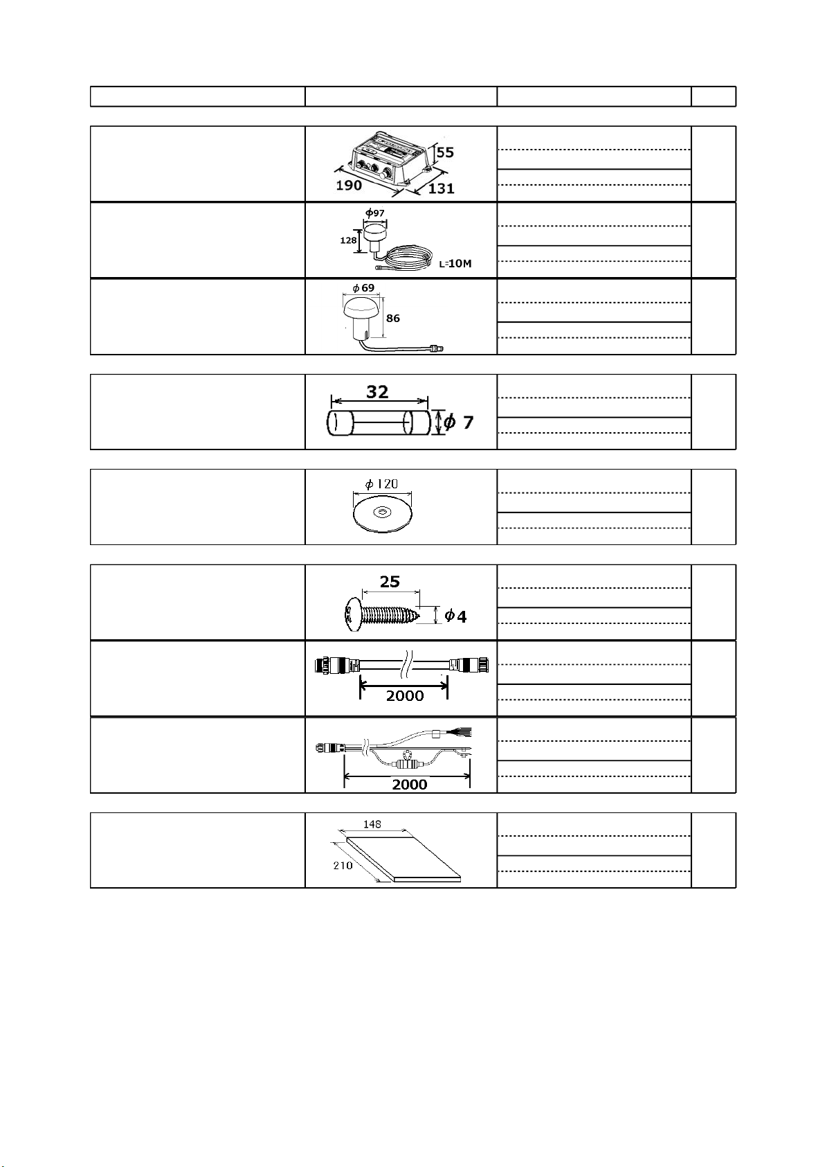
O U T L I N E
Q'TY
A C K I N G L I S TP
999-999-551-10
000-194-113-13
000-192-734-12
999-999-551-40
000-197-449-10
999-999-551-70
999-999-551-60
999-999-551-50
000-197-396-1*
A-1
FA-70-E/-E-S
05EW-X-9853 -3
1/1
N A M E
ユニット UNIT
簡易船舶識別装置
CLASS B AIS TRANSPONDER
アンテナ
ANTENNA UNIT
アンテナ
ANTENNA UNIT
予備品 SPARE PARTS
ヒューズ
TUBE FUSE
付属品 ACCESSORIES
AISセッティングツール
AIS SETTING TOOL
DESCRIPTION/CODE №
FA-70
GPA-C01
GPA-017S
250VAC 5A
FA70/60/40 SW *CD*
1
(*)
1
(*1)
1
(*2)
2
(*)
1
工事材料 INSTALLATION MATERIALS
+トラスタッピンネジ1シュ
TAPPING SCREW
NMEA2000ケーブル
NMEA2000 CABLE
電源データケーブル
PWR/NMEA1/SILENT CABLE
図書 DOCUMENT
取扱説明書(英)
OPERATOR'S MANUAL (EN)
PA4x25
NPD-MM1MF1000G02M
61110000000101
OME-45150-*
4
(*)
1
(*)
1
(*)
1
(*)は、ダミーコードに付き、注文できません。
(*) THIS CODE CANNOT BE ORDERED.
(*1)は、FA-70-E用です。
(*1): FOR FA-70-E.
(*2)は、FA-70-E-S用です。
(*2): FOR FA-70-E-S.
(略図の寸法は、参考値です。 DIMENSIONS IN DRAWING FOR REFERENCE ONLY.)
C4515-Z01-D
Page 46
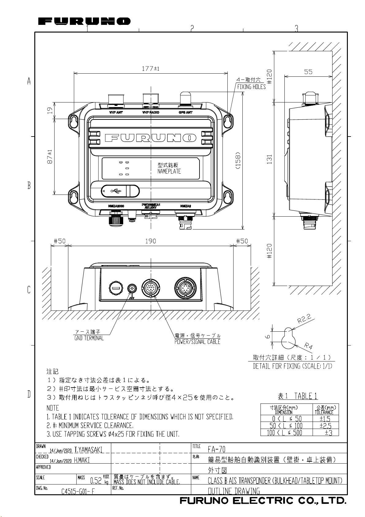
D-1
28/Jan/2020 H.MAKI
Page 47
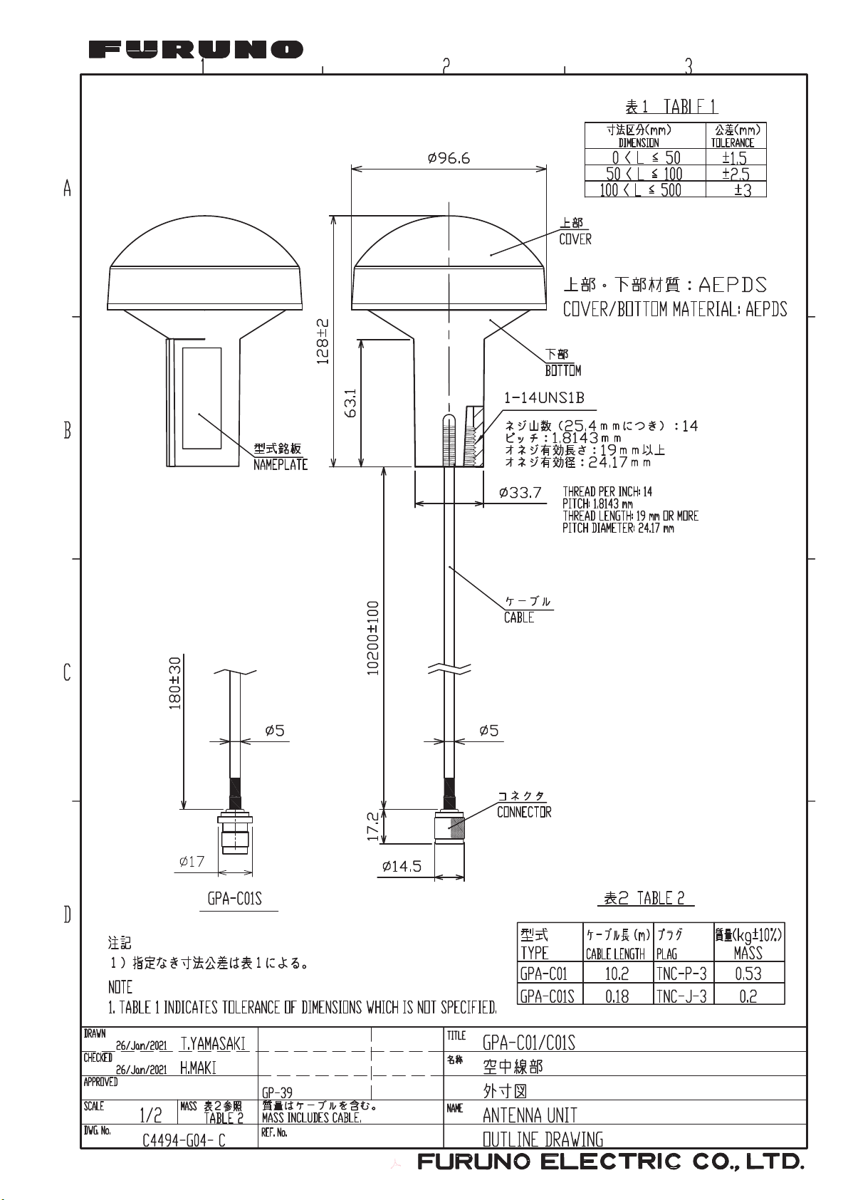
D-2
28/Jan/2021 H.MAKI
Hiromasa
Maki
電子署名者 : Hiromasa
Maki
日付 : 2021.01.28 09:41:54
+09'00'
Page 48
D-3
Mar.27'07R.Esumi
Page 49
GP-1871F/1971F
S-
1
19/Aug/2021 H.MAKI
TZT9/14/BB
TZTL12F/15F,TZT2BB
TZT9F/12F/16F/19F
ETC.
FI-70
*2
FA-70
簡易型船舶自動識別装置
相互結線図
CLASS B AIS TRANSPONDER
INTERCONNECTION DIAGRAM
43
*2
VHF空中線部
VHF ANTENNA
CX4-3/FEC
*1
GPS空中線部(選択)
M-P-5
*1
5D-2V
M-P-5
GPS ANTENNA (SELECT)
*2
GPA-017S
GPA-C01
GPA-017
0.2m
10m
*2
TNCP-NJ
*2
10m
TNC-P-3
終端器
TERMINATOR*2FRU-MM1000000001 OR
N-P-8DSFA
*1
8D-FB-CV,30/40/50m *2
RG-10/UY,20m MAX.
TNC-PS-3D-15,15m
*2
NJ-TP-3DXV,1m
Tコネクタ
T-CONNECTOR
FRU-MF000000001
FRU-MM1MF1MF1001
RED
BLK
アカクロシロ
NPD-MM1MF1000G02M,2m
12345
WHT
アオ BLU
パソコン
*1
USB CABLE,2m MAX.
5
TYPE B
TITLE
15VDC
PC
T.YAMASAKI
18/Aug/2021
DRAWN
名 称
CHECKED
H.MAKI
19/Aug/2021
APPROVED
NAME
SCALE MASS
05-113-1001-0
REF.No.
kg
C4515-C01- F
DWG.No.
J1
J2
GPS ANT
NET-S
SHIELD
NMEA2000
NET-C
NET-H
NET-L
USB
*1
IV-1.25sq.
2
DC_IN-
VHF RADIO VHF ANT
J3
M-P-5
*1
5D-2V
VHF送受信機
簡易型船舶自動識別装置
CLASS B AIS TRANSPONDER
FA-70
NMEA2
*2
MJ-A6SPF0003,15m MAX.
TD-A
TD-BNCGND
RD-H
RD-C
12345
WHT
YEL
GRN
クロ BLK
シロキミドリ
PWR/NMEA1/SILENT
6
5A
61110000000101,2m
DC_IN+
DC_IN+
1
2
RED
BLK
アカ
クロ
(+)
(-)
8
DC_IN-
NMEA1_TD-AWHTシロ 11
9
NMEA1_TD-BBRNチャ
3
NMEA1_RD-H
12
YEL
キ
NMEA1_RD-C
7
GRN
ミドリ
EXT_SILENT-H
EXT_SILENT-C
4
6
PPL
GRY
ムラサキ
ハイ
10 GND
DRAINドレイン GND5
1
VHF RADIOTELEPHONE
12-24VDC
NAV EQUIPMENT OR SENSOR
航法機器または
センサー
航法機器または
センサー
外部スイッチ
NAV EQUIPMENT OR SENSOR
EXTERNAL SWITCH
注記
*1)造船所手配。
*2)オプション。
NOTE
*1: SHIPYARD SUPPLY.
*2: OPTION.
A
B
C
Page 50

Declaration of Conformit
y
(BG)
(ES)
(CS)
(DA)
(DE)
(ET)
(EL)
(EN)
(FR)
(HR)
(IT)
(LV)
p
quip
p
[FA-70]
Bulgarian
Spanish
Czech
Danish
German
Estonian
С настоящото Furuno Electric Co., Ltd. декларира, че гореспоменат тип
радиосъоръжение е в съответствие с Директива 2014/53/ЕС, SI 2017/1206.
Цялостният текст на EC/UK декларацията за съответствие може да се намери
на следния интернет адрес:
Por la presente, Furuno Electric Co., Ltd. declara que el tipo de equipo radioeléctrico
arriba mencionado es conforme con la Directiva 2014/53/UE, SI 2017/1206.
El texto completo de la declaración de conformidad de la EU/UK está disponible en
la siguiente dirección Internet:
Tímto Furuno Electric Co., Ltd. prohlašuje, že výše zmíněné typ rádiového
zařízení je v souladu se směrnicí 2014/53/EU, SI 2017/1206.
Úplné znění EU/SK prohlášení o shodě je k dispozici na této internetové adrese:
Hermed erklærer Furuno Electric Co., Ltd., at ovennævnte radioudstyr er i
overensstemmelse med direktiv 2014/53/EU, SI 2017/1206.
EU/UK-overensstemmelseserklæringens fulde tekst kan findes på følgende
internetadresse:
Hiermit erklärt die Furuno Electric Co., Ltd., dass der oben genannte
Funkanlagentyp der Richtlinie 2014/53/EU, SI 2017/1206 entspricht.
Der vollständige Text der EU/UK-Konformitätserklärung ist unter der folgenden
Internetadresse verfügbar:
Käesolevaga deklareerib Furuno Electric Co., Ltd., et ülalmainitud raadioseadme
tüü
vastab direktiivi 2014/53/EL, SI 2017/1206 nõuetele.
EL/GB vastavusdeklaratsiooni täielik tekst on kättesaadav järgmisel
internetiaadressil:
Greek
English
French
Croatian
Italian
Latvian
Με την παρούσα η Furuno Electric Co., Ltd., δηλώνει ότι ο προαναφερθέντας
ραδιοεξοπλισμός πληροί την οδηγία 2014/53/ΕΕ, SI 2017/1206.
Το πλήρες κείμενο της δήλωσης συμμόρφωσης EE/UK διατίθεται στην ακόλουθη
ιστοσελίδα στο διαδίκτυο:
Hereby, Furuno Electric Co., Ltd. declares that the above-mentioned radio
ment type is in compliance with Directive 2014/53/EU, SI 2017/1206.
e
The full text of the EU/UK declaration of conformity is available at the following
internet address:
Le soussigné, Furuno Electric Co., Ltd., déclare que l'équipement radioélectrique
du type mentionné ci-dessus est conforme à la directive 2014/53/UE, SI 2017/1206.
Le texte complet de la déclaration UE/RU de conformité est disponible à l'adresse
internet suivante:
Furuno Electric Co., Ltd. ovime izjavljuje da je gore rečeno radijska oprema tipa
u skladu s Direktivom 2014/53/EU, SI 2017/1206.
Cjeloviti tekst EU/UK izjave o sukladnosti dostupan je na sljedećoj internetskoj
adresi:
Il fabbricante, Furuno Electric Co., Ltd., dichiara che il tipo di apparecchiatura
radio menzionato so
Il testo completo della dichiarazione di conformità UE/RU è disponibile al seguente
indirizzo Internet:
Ar šo Furuno Electric Co., Ltd. deklarē, ka augstāk minēts radioiekārta atbilst
Direktīvai 2014/53/ES, SI 2017/1206.
Pilns ES/AK atbilstības deklarācijas teksts ir pieejams šādā interneta vietnē:
ra è conforme alla direttiva 2014/53/UE, SI 2017/1206.
Page 51

Lithuanian
(LT)
(HU)
(MT)
(NL)
(PL)
(RO)
k
(SK)
(SL)
(FI)
(SV)
pp
ą
.
y
Aš, Furuno Electric Co., Ltd., patvirtinu, kad pirmiau minėta radijo įrenginių tipas
atitinka Direktyvą 2014/53/ES, SI 2017/1206.
Visas ES/JK atitikties deklaracijos tekstas prieinamas šiuo interneto adresu:
Hungarian
Maltese
Dutch
Polish
Portuguese
(PT)
Furuno Electric Co., Ltd. igazolja, hogy fent említett típusú rádióberendezés
megfelel a 2014/53/EU, SI 2017/1206 irányelvnek.
Az EU/EK-megfelelőségi nyilatkozat teljes szövege elérhető a következő internetes
címen:
B'dan, Furuno Electric Co., Ltd., niddikjara li msemmija hawn fuq-tip ta' tagħmir
tar-radju huwa konformi mad-Direttiva 2014/53/UE, SI 2017/1206.
It-test kollu tad-dikjarazzjoni ta' konformità tal-UE/RU huwa disponibbli
f'dan l-indirizz tal-Internet li ġej:
Hierbij verklaar ik, Furuno Electric Co., Ltd., dat het hierboven genoemde type
radioa
De volledige tekst van de EU/VK-conformiteitsverklaring kan worden geraadpleegd
op het volgende internetadres:
Furuno Electric Co., Ltd. niniejszym oświadcza, że wyżej wymieniony typ
urz
Pełny tekst deklaracji zgodności UE/UK jest dostępny pod następującym adresem
internetow
O(a) abaixo assinado(a) Furuno Electric Co., Ltd. declara que o mencionado
acima tipo de equipamento de rádio está em conformidade com a Diretiva
2014/53/UE, SI 2017/1206.
O texto integral da declaração de conformidade da EU/UK está disponível no
seguinte endereço de Internet:
aratuur conform is met Richtlijn 2014/53/EU, SI 2017/1206.
dzenia radiowego jest zgodny z dyrektywą 2014/53/UE, SI 2017/1206
m:
Romanian
Slova
Slovenian
Finnish
Swedish
Prin prezenta, Furuno Electric Co., Ltd. declară că echipamentul radio menționat
mai sus este în conformitate cu Directiva 2014/53/UE, SI 2017/1206.
Textul integral al declarației de conformitate UE/RU este disponibil la următoarea
adresă internet:
Furuno Electric Co., Ltd. týmto vyhlasuje, že vyššie spomínané rádiové
zariadenie typu je v súlade so smernicou 2014/53/EÚ, SI 2017/1206.
Úplné EÚ/SK vyhlásenie o zhode je k dispozícii na tejto internetovej adrese:
Furuno Electric Co., Ltd. potrjuje, da je zgoraj omenjeno tip radijske opreme
skladen z Direktivo 2014/53/EU, SI 2017/1206.
Celotno besedilo izjave EU/ZK o skladnosti je na voljo na naslednjem spletnem
naslovu:
Furuno Electric Co., Ltd. vakuuttaa, että yllä mainittu radiolaitetyyppi on
direktiivin 2014/53/EU, SI 2017/1206 mukainen.
EU/UK-vaatimustenmukaisuusvakuutuksen täysimittainen teksti on saatavilla
seuraavassa internetosoitteessa:
Härmed försäkrar Furuno Electric Co., Ltd. att ovan nämnda typ av
radioutrustning överensstämmer med direktiv 2014/53/EU, SI 2017/1206.
Den fullständiga texten till EU/Storbritannien-försäkran om överensstämmelse finns
på följande webbadress:
Online Resource
http://www.furuno.com/en/support/red_doc
Notice for radiated immunity
The test for the radiated immunity is performed up to 2.7 GHz only without the special condition
of spot frequency being applied. There is a chance that this equipment may interfere with
allocated services in the frequency range of 2.7 GHz to 6 GHz, particularly in harbors, rivers,
lake banks, etc.
 Loading...