

Page 1
INSTALLATION INSTRUCTIONSOWNER’S GUIDE &
External-Mount, 2 -3kW
Transducer
Models: R99, R209, R309
R109LH, R109LM, R509LH, R509LM, R609LH, R609LM
U.S. Patent No. 7,369,458. UK Patent No. 2 414 077. U.S. Patents Pending
Follow the precautions below for optimal product
performance and to reduce the risk of property
damage, personal injury, and/or death.
WARNING: Boats capable of speeds above 25kn
(29MPH)—You must follow these instructions for a safe
17-335-01 rev. 09 09/08/11
installation. For boats exceeding 35 kn. (40MPH) or when
the instructions cannot be met, mount an in-hull
transducer. At high speeds, the fairing and/or transducer
may break away from the boat.
WARNING: A stuffing tube is required. The stuffing tube
seals the hull forming a water-tight conduit for the cable.
WARNING: The fairing must be installed parallel to the
keel to ensure proper boat handling and water flow under
the transducer.
WARNING: Always wear safety goggles and a dust mask
when installing to prevent personal injury.
WARNING: Immediately check for leaks when the boat is
placed in the water. Do not leave the boat in the water
unchecked for more than three hours. Even a small leak
may allow considerable water to accumulate.
WARNING: Fiberglass hull—The transducer and stuffing
tube must be installed in solid fiberglass, not in coring
CAUTION: Aluminum hull—The stainless steel hardware
must be isolated from an aluminum hull to prevent
electrolytic corrosion.
CAUTION: Steel hull—Follow generally accepted
installation practices.
CAUTION: Never install a metal fitting in a vessel with a
positive ground system.
CAUTION: External mount only. The transducer will
overheat if it is mounted in a hull pocket.
CAUTION: Never pull, carry, or hold the transducer by its
cable. This may sever internal connections.
CAUTION: Never strike the transducer.
CAUTION: Tighten the nylon locking nuts with a torque
wrench using a force not exceeding 27N-m (20ft.-lb.). Do
not over tighten. It may crack the transducer and/or crush
the fairing.
CAUTION: Never use solvents. Cleaners, fuel, paint,
sealants, and other products may contain strong solvents,
such as acetone, which attack many plastics greatly
reducing their strength.
with Temperature Sensor
Record the information found on the cable tag for future reference.
Part No.:_________________Date___________Frequency________kHz
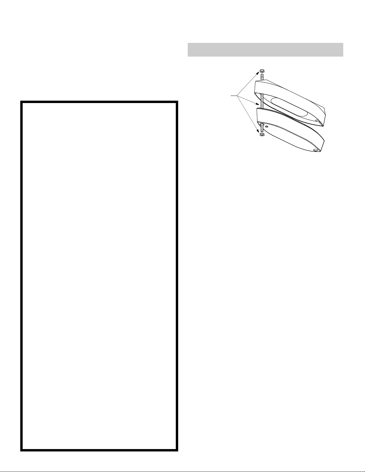
Remove
and discard
the packing
hardware.
Figure 1. Packing hardware
Copyright © 2007 Airmar Technology Cor p.
IMPORTANT: Please read the instructions completely before
proceeding with the installation. These instructions supersede any
other instructions in your instrument manual if they differ.
fairing
transducer
Applications
• Recommended for all hull materials
• Not recommended for hulls less than 9m (30') long
• Not recommended for stepped hulls. Mount an in-hull transducer
• Accommodates a deadrise angle up to 22
°
Unpacking & Pretest
Remove and discard the packing hardware (rod and 2 nuts) (see
Figure 1). Connect the temperature function to the instrument and
check for the approximate air temperature. If there is no reading
or it is inaccurate, check the connections and test again. If there is
still a problem, return the product to your place of purchase.
Tools & Materials
Safety goggles
Dust mask
Angle finder or digital level
Band saw (blade must be very sharp)
Rasp or power tool
Electric drill
Drill bits: pilot hole 3mm or 1/8"
fiberglass, wood, or steel hull14mm or 9/16"
aluminum hull 15mm or 9/16"
Permanent marker
Mild household detergent or weak solvent (such as alcohol)
Sandpaper
File (installation in a metal hull)
Marine sealant (suitable for below waterline)
Wrenches
Torque wrench
Grommet(s) (some installations)
Cable ties
Water-based anti-fouling paint (mandatory in salt water)
Page 2
pressure waves
1/3
LWL
(Load Waterline Length)
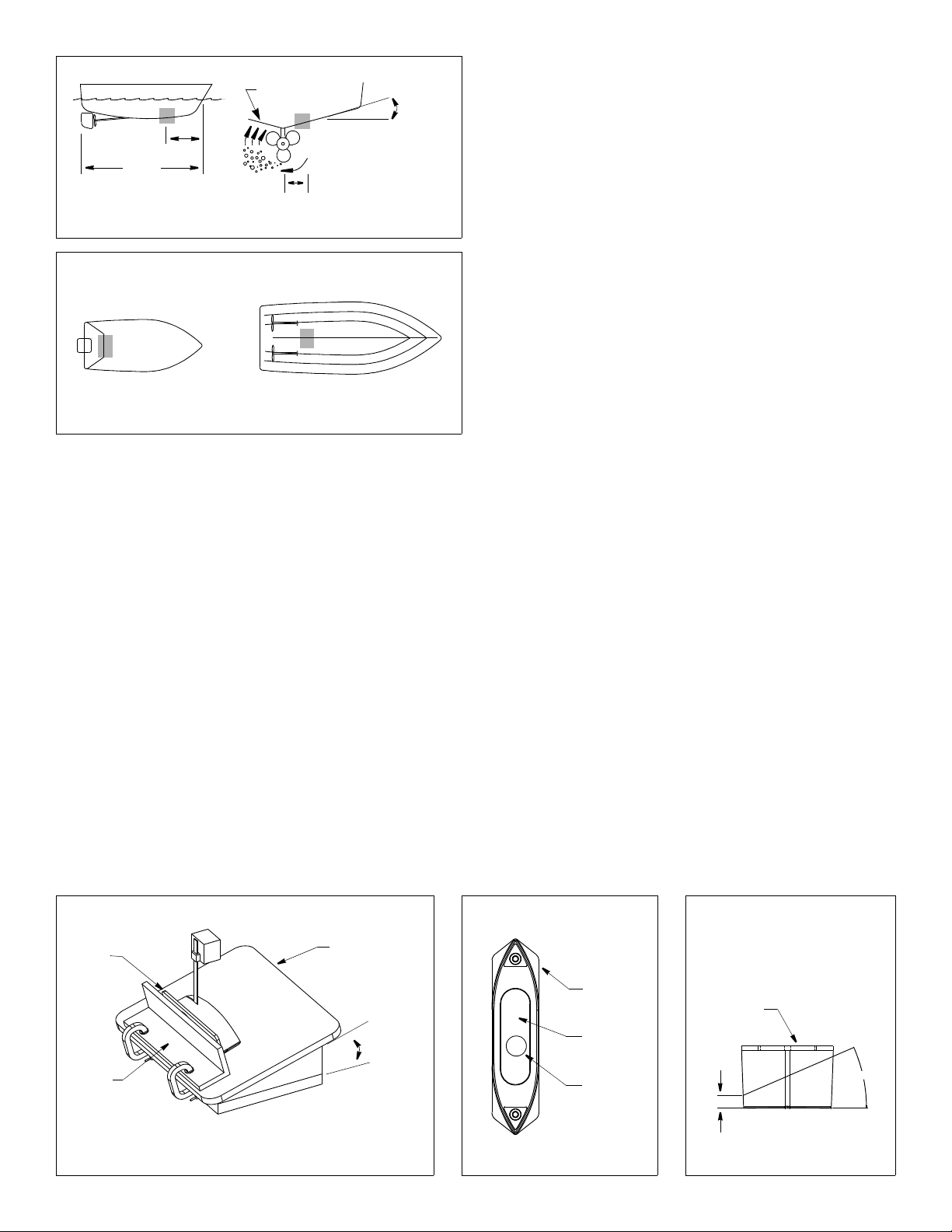
Figure 2. Transducer location on displacement hull
NOTE: Mount within the
aft 1/3 of the hull, as far
back as possible.
Copyright © 2005 Airmar Technology Cor p.
200- 600mm
(8 – 24")
slope of hull
deadrise
angle
parallel to
waterline
• The transducer must be continuously immersed in water.
• The transducer beam must be unobstructed by the keel or
propeller shaft(s).
• Choose a location away from interference caused by power and
radiation sources such as: the propeller(s) and shaft(s), other
machinery, other echosounders, and other cables. The lower
the noise level, the higher the echosounder gain setting that
can be used.
• Choose a location with a minimum deadrise angle, not to
exceed 22
°.
• Choose an accessible spot inside the vessel with adequate
headroom for the height of the stuffing tube and tightening the nuts.
Stuffing Tube
After determining the best mounting location for the transducer,
install the stuffing tube. Follow the installation instructions
packaged with the stuffing tube.
outboard and I/O
Figure 3. Transducer location on planing hull
Copyright © 2005, 2009 Airmar Techn ology Corp.
inboard
Mounting Location
Hull Types
• Displacement hull powerboat—Locate about 1/3 of the way
along the LWL and 200– 600mm (8– 24") off the centerline (see
Figure 2). The starboard side of the hull where the propeller
blades are moving downward is preferred.
• Planing hull powerboat— (see Figure 3)
• Mount within the aft 1/3 of the hull, as far back as possible.
Outboard and I/O—Mount just forward of the engine(s).
Inboard—Mount ahead of the propeller(s) and shaft(s).
• Mount on or as close to the centerline as possible, and well
inboard of the first set of lifting strakes to ensure that the
transducer is in contact with the water at high speeds.
• Mounting on the starboard side of the hull where the
propeller blades are moving downward is preferred.
Placement Guidelines
CAUTION: Do not mount near water intake or discharge openings
or behind strakes, fittings, or hull irregularities that will disturb the
water flow.
• The water flowing under the hull must be smooth with a
minimum of bubbles and turbulence (especially at high speeds).
Fairing: Cutting, Bedding & Installing
Cutting the Fairing
CAUTION: Shape the fairing to the hull as precisely as possible. If
there are gaps between the fairing and the hull near the ends, cut
a new fairing. Over tightening the rods to minimize gaps may
crack the transducer and/or crush the fairing.
1. Measure the deadrise angle of the hull at the stuffing tube using
an angle finder or digital level (see Figure 2).
2. Tilt the band saw table to the measured angle and secure the
cutting fence (see Figure 4). Do not exceed 22°.
3. Place the fairing on the table so the cutting guide rests against
the fence (see Figures 4 and 5). Note the fairing is symmetrical.
4. Adjust the fence so the fairing will be cut in about two equal parts.
The section that will become the fairing must be a minimum of
20mm (3/4") at its thinnest dimension (see Figure 6).
5. Recheck steps 1 through 4; then cut the fairing.
6. Check the fit by placing the fairing against the hull. Be sure the
fairing is parallel to the centerline of the boat (keel), and the
stuffing tube is about 2/3 of the way back in the cavity (see
Figure 5). Hold the fairing on the ends and try to rock it back
and forth. Shape the fairing to the hull as precisely as possible
with a rasp or power tool until it no longer rocks.
7. The remaining section of the fairing with the cutting guide will
be used as the backing block inside the hull. It will provide a
level surface for tightening the nuts on the threaded rods.
2
cutting
guide
fence
Figure 4. Cutting the fairing
Copyright © 2005 Airmar Technolog y Corp.
band saw
table
deadrise
angle
bottom view aft view
Bow
location
of stuffing
tube
Figure 5. Fairing
Copyright © 2007 - 2011 Airmar Techno logy Corp. Copyright © 2005 Airmar Technology Corp.
cutting
guide
cavity for
stuffing
tube
>
NOTE
: After the fairing is cut,
the section with the cutting guide
becomes the backing block.
cutting
guide
20mm
(3/4")
min.
22
Figure 6. Fairing
max
°
Page 3

threaded
rod (2)
(uncolored)
backing
block
hull
fairing
stuffing
tube
A
Bow >
marine
sealant on
washers (2),
backing block,
rods (2)
marine
sealant on
fairing,
recess
70mm
(2-3/4")
102mm
(4")
sleeve for
installation
in aluminum
hull only
metal nut
& washer
color this
section of
rod with
permanent
marker
Figure 7. Bedding and installing the fairing and backing block (non-metal hull shown)
Copyright © 2007 Airmar Technology Corp.
Dry Fitting the Fairing
1. To locate the hole for the forward threaded rod (nearest the bow),
measure the distance between the cable exit and the forward hole
in the transducer, center to center. (The rounded bottom is
forward and the temperature sensor is aft.) Being sure the
fairing will be parallel to the centerline of the boat (keel),
measure this distance A on hull and mark the hole (see Figure 7).
2. Drill a pilot hole at the marked location. Using the appropriate
size drill bit, drill the hole through the hull for one threaded rod.
Do not drill the second hole at this time.
3. Prepare the threaded rods (see Figure 8). Using a permanent
marker, draw a line on each threaded rod 102mm (4") from the
end and color this section. (The colored section will be used to
fasten the transducer to the fairing.) Screw a nut onto the colored
section of each threaded rod above the 102mm (4") line drawn.
4. Place the fairing against the hull. Push the uncolored end of the
threaded rod through the fairing and the hull until the nut rests
inside the recess in the fairing (see Figure 7). With a person
stationed inside the vessel, slide the backing block onto the rod.
Temporarily secure the rod with a stainless steel washer and nut.
5. Align the fairing parallel to the centerline of the boat (keel).
Using the aft hole in the fairing as a guide, drill a pilot hole.
Then drill the hole using the appropriate size drill bit.
6. Remove the fairing from the hull. Clean and sand the area
around the holes, inside and outside, to ensure that the marine
sealant will adhere properly. Remove any petroleum residue with
a mild household detergent or a weak solvent such as alcohol.
Metal hull—Remove all burrs with a file and sandpaper.
Figure 8. Threaded rod
Copyright © 2007 Airmar Technolog y Corp.
Bedding & Installing the Fairing
CAUTION: Be sure the surfaces to be bedded are clean and dry.
1. If there is any residue on the fairing and transducer, remove it
with a mild household detergent to ensure the marine sealant
will adhere properly.
2. Apply a 2mm (1/16") thick layer of marine sealant: (see Figure 7)
• To the surface of the backing block that will contact the hull
• To the surface of the fairing that will contact the hull
• To the recesses in the fairing for the washers and nuts
• To the threaded rods
• To the surface of the washers that will contact the backing block
NOTE: Be sure the rods have marine sealant on the threads under
the nuts. Back each nut off 13mm (1/2") and apply sealant to the
threads. Then return each nut to the marked location on the rod.
3. Slide a washer along the uncolored section of each threaded
rod until it rests against the nut (see Figure 8).
Aluminum hull—The stainless steel rods must be isolated from
an aluminum hull to prevent electrolytic corrosion. Cut the
sleeving 70mm (2-3/4"). Slide the isolation sleeve over the
uncolored section of each bedded rod as far down as possible.
Apply a 2mm (1/16") thick layer of the marine sealant to the
outside of the sleeving.
4. Push the uncolored section of each threaded rod through the
fairing, the hull, and the backing block until the washer rests inside
the recess in the fairing (see Figure 7). With a person stationed
inside the vessel, secure each rod with a washer (bedded side
against the backing block) and double stainless steel nuts. Use
metal nut (4)
and washer (2)
backing block
hull
fairing
washer (2)
metal nut (2)
transducer
washer (2)
nylon nut (2)
foam plug (2)
threaded
rod (2)
temperature
sensor
cable
stuffing
tube
Figure 9. Bedding and installing the transducer
Copyright © 2007 Airmar Technology Corp.
(non-metal hull shown)
marine sealant on
transducer that contacts
fairing and recess
rounded bottom
marine sealant
flush with hull
Bow >
3
Page 4

a wrench to hold the lower nut while tightening the top nut
against it.
Aluminum hull—The top of the isolation sleeve must be below
the top of the backing block to prevent the sleeving from
interfering with tightening the nuts.
Wood hull—Allow the wood to swell before tightening the nuts.
Transducer: Bedding & Installing
1. Apply a 2mm (1/16") thick layer of marine sealant to the surface
of the transducer that will contact the fairing including the
recesses for the washers and nuts (see Figure 9).
2. Thread the transducer cable through the stuffing tube.
3. Slide the transducer onto the threaded rods being sure the
rounded bottom is facing forward toward the bow and the
temperature sensor is aft. Seat the transducer firmly within the
recess in the fairing. Secure the transducer in place by applying
a washer and a nylon locking nut to each threaded rod.
Tighten each nut with a torque wrench using a force not
exceeding 12N-m (10ft.-lb.). Then tighten each nut again using
a force not exceeding 27N-m (20ft.-lb.). Do not over tighten as it
may crack the transducer and/or crush the fairing. Be sure the
rods extend a minimum of 3 threads beyond the nut after
being tightened.
4. Plug the mounting holes to minimize turbulence on the surface
of the transducer. Be sure there is marine sealant on the
exposed threads of the rods. Cut the white foam plugs to length
so that when installed, each plug is recessed 5mm (3/16")
below the surface of the transducer. Push the foam plugs into
the holes. Use marine sealant to fill the remaining recess flush
with the transducer’s surface.
5. Remove excess marine sealant on the outside of the hull to
ensure smooth water flow under the transducer.
cable
aft view
Figure 10. Completed installation (non-metal hull shown)
Copyright © 2005 Airmar Technolog y Corp.
stuffing tube
backing block
hull
fairing
transducer
Maintenance, Repair & Replacement
Anti-fouling Paint
Surfaces exposed to salt water must be coated with anti-fouling
paint. Use water-based anti-fouling paint only. Never use ketonebased paint since ketones can attack many types of plastic
possibly damaging the transducer. Reapply anti-fouling paint
every 6 months or at the beginning of each boating season.
Cleaning
Aquatic growth can accumulate rapidly on the transducer’s
surface reducing its performance within weeks. Clean it using a
Scotch-Brite® scour pad and mild household detergent, being
careful to avoid making scratches. In severe cases, lightly wet
sand the surface with fine grade wet/dry paper.
Sealing & Routing the Cable
To form a watertight seal inside the stuffing tube, follow the
installation instructions that came with your stuffing tube. The
completed installation will look like Figure 10.
Route the cable to the echosounder being careful not to tear the
cable jacket when passing it through the bulkhead and other parts
of the boat. Use grommets to prevent chafing. To reduce electrical
interference separate the transducer cable from other electrical
wiring and the engine. Coil any excess cable and secure it in
place with cable ties to prevent damage.
Refer to your echosounder owners manual to connect the cable to
the instrument.
Checking for Leaks
When the boat is placed in the water, immediately check around
the threaded rods and the stuffing tube for leaks. Note that very
small leaks may not be readily observed. It is best not to leave the
boat in the water unattended for more than 3 hours before
rechecking. If there is a small leak, there may be considerable
bilge water accumulation after 24 hours. If a leak is observed,
repeat the bedding and installing procedures beginning on page 3
immediately.
Replacement Transducer & Parts
The information needed to order a replacement Airmar transducer is
printed on the cable tag. Do not remove this tag. When ordering,
specify the part number, date, and frequency in kHz. For convenient
reference, record this information on the top of page one.
Fairing & Stuffing Tube 33-439-01
Obtain parts from your instrument manufacturer or marine dealer.
Gemeco Tel: 803-693-0777
(USA) Fax: 803-693-0477
email: sales@gemeco.com
Airmar EMEA Tel: +33.(0)2.23.52.06.48
(Europe, Middle East, Africa) Fax: +33.(0)2.23.52.06.49
email: sales@airmar-emea.com
®
AIRMAR
TECHNOLOGY CORPORATION
4
35 Meadowbrook Drive, Milford, New Hampshire 03055-4613, USA
•
Copyright © 2005 - 2011 Airmar Technology Corp. All rights reserved.
www.airmar.com
 Loading...