

Page 1

INTEGRATED HEADING SENSOR PG-500
Back
FLUXGATE HEADING SENSOR C-500
Page 2

TABLE OF CONTENTS
SAFETY INSTRUCTIONS...................................................................................... i
FOREWORD .........................................................................................................ii
SYSTEM CONFIGURATION................................................................................iii
EQUIPMENT LIST................................................................................................ iv
1. OPERATION......................................................................................................1
1.1 Controls and Indications....................................................................................................1
1.2 Turning the Powe r On/Off.................................................................................................. 1
1.3 Automatic Distortion Compensation...................................................................................3
1.4 Damping Control...............................................................................................................3
1.5 Selecting Ou tput Data Format...........................................................................................4
2. MAINTENANCE & TROUBLESHOOTING
2.1 Maintenance......................................................................................................................5
2.2 Troubleshooting.................................................................................................................5
2.3 Diagnostic Test..................................................................................................................6
2.4 Error Status.......................................................................................................................7
2.5 Clearing the Memory.........................................................................................................7
3. INSTALLATION
3.1 Mounting...........................................................................................................................8
3.2 Connections......................................................................................................................9
3.3 Correcting Magnetic Field Distortion................................................................................10
3.4 Heading Alignment.......................................................................................................... 11
3.5 Setting Output Data.........................................................................................................12
3.6 Setting Baud Rate...........................................................................................................13
SPECIFICATIONS...........................................................................................SP-1
PACKING LIST.................................................................................................. A-1
OUTLINE DRAWING
INTERCONNECION DIAGRAM
Page 3
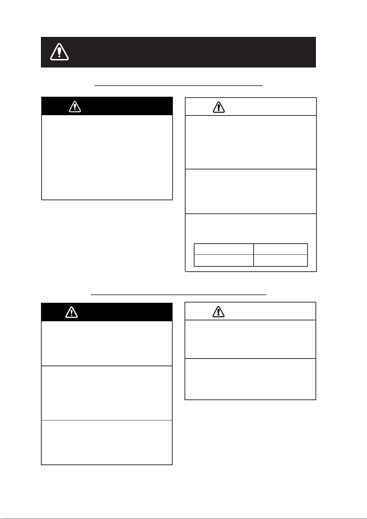
SAFETY INSTRUCTIONS
Safety Information for the Installer
WARNINGWARNING
Turn off the power at the mains
switchboard before beginning the
installation.
Post a sign near the switch to indicate
it should not be turned on while the
equipment is being installed.
Fire or electrical shock can result if the
power is left on or is applied while the
equipment is being installed.
CAUTION
Confirm that the power supply voltage
is compatible with the voltage rating
of the equipment.
Connection to the wrong power supply
can cause fire or damage the equipment.
Use the supplied power cable.
Use of a wrong power cable can cause
fire or damage the equipment.
Maintain the compass safe distance to
prevent deviation to a magnetic
compass.
Standard compass
0.3 m
Steering compass
0.3 m
Safety Information for the Operator
WARNINGWARNING
Do not disassemble or modify the
equipment.
Fire, electrical shock or serious injury can
result.
Turn off the power immediately if water
leaks into the equipment or the
equipment is emitting smoke or fire.
Continued use of the equipment can cause
fire or electrical shock.
Do not place liquid-filled containers on
the top of the equipment.
Fire or electrical shock can result if a liquid
spills into the equipment.
CAUTION
Turns off the autopilot before selecting
output data format.
The autopilot may turn the rudder suddenly.
Turns off the autopilot before aligning
heading.
The autopilot may turn the rudder suddenly.
i
Page 4

FOREWORD
A Word to PG-500/C-500 Owners
Congratulations on your choice of the FURUNO PG-500 Integrated Heading Sensor, C-500
Fluxgate Heading Sensor. We are confident you will see why the FURUNO name has become
synonymous with quality and reliability.
For over 50 years FURUNO Electric Company has enjoyed an enviable reputation for inno vat ive
and dependable marine electronics equipment. This dedication to excellence is furthered by our
extensive global network of sales and service.
Your heading sensor is designed and constructed to meet the rigorous demands of the marine
environment. However, no machine can perform its intended function unless installed, operated
and maintained properly. Please carefully read and follow the recommended procedures for
installation, operation and maintenance.
We would appreciate hearing from you about whether we are achieving our purposes.
Thank you for choosing FURUNO equipment.
Features
• The PG-500 uses a fluxgate magnetic sensor in conjunction with a solid-state angular rate
heading.
• The C-500 uses a fluxgate magnetic sensor.
• The PG-500/C-500 can correct magnetic devia tion automatically.
• The PG-500/C-500 can convert magnetic heading to true head ing (requires FURUNO GPS
Navigator).
ii
Page 5
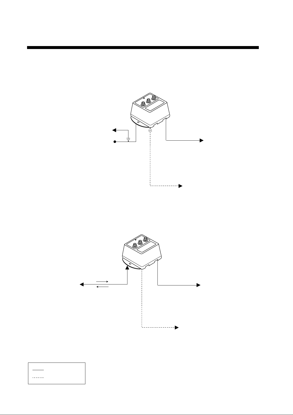
SYSTEM CONFIGURATION
Standard connection
PG-500/C-500
EXTERNAL EQUIPMENT
(NAVnet series, etc.)
12-24 VDC
Connection with NAVpilot-500
NMEA
Format
PG-500
NMEA
Format
AD-10 Format
RADAR/ARPA
(MODEL1832, 1721Mk-2, etc.)
EXTERNAL EQUIPMENT
(NAVnet series, etc.)
NAVpilot-500
Processor unit
Standard Supply
User Supply
Power,
operation command
NMEA Format
(Magnetic heading)
AD-10 Format
(Magnetic heading)
RADAR/ARPA
(MODEL1832, 1721Mk-2, etc.)
NMEA Format
(Magnetic heading)
EXTERNAL EQUIPMENT
(NAVnet series, etc.)
iii
Page 6

v
EQUIPMENT LIST
Standard set
Name Type Qty Remarks
PG-500-E Fluxgate and rate sensor
Sensor
C-500-E
Installation Materials CP64-02100 1 set Refer to the packing list at the back of this manual.
1
Fluxgate sensor
Spare Parts
Option
Name Type Code No. Qty Remarks
Cable assy.
SP64-01301 1 set Fuse
(Type: FGMB 1A 125V, Code No.: 000-114-805)
MJ-A6SPF0003-050 000-117-603 1
MJ-A6SPF0007-100 000-125-237 1 6P-6P, 10 m (for AD-10 format)
MJ-A7SPF0006-100 000-143-578 1 7P-7P, 10 m (for NMEA/Power)
MJ-A7SPF/SRMD-100 000-144-534 1 For extension. 7P-7P, 10 m
6P connector, 5 m
(for AD-10 format, NMEA)
i
Page 7
1. OPERATION
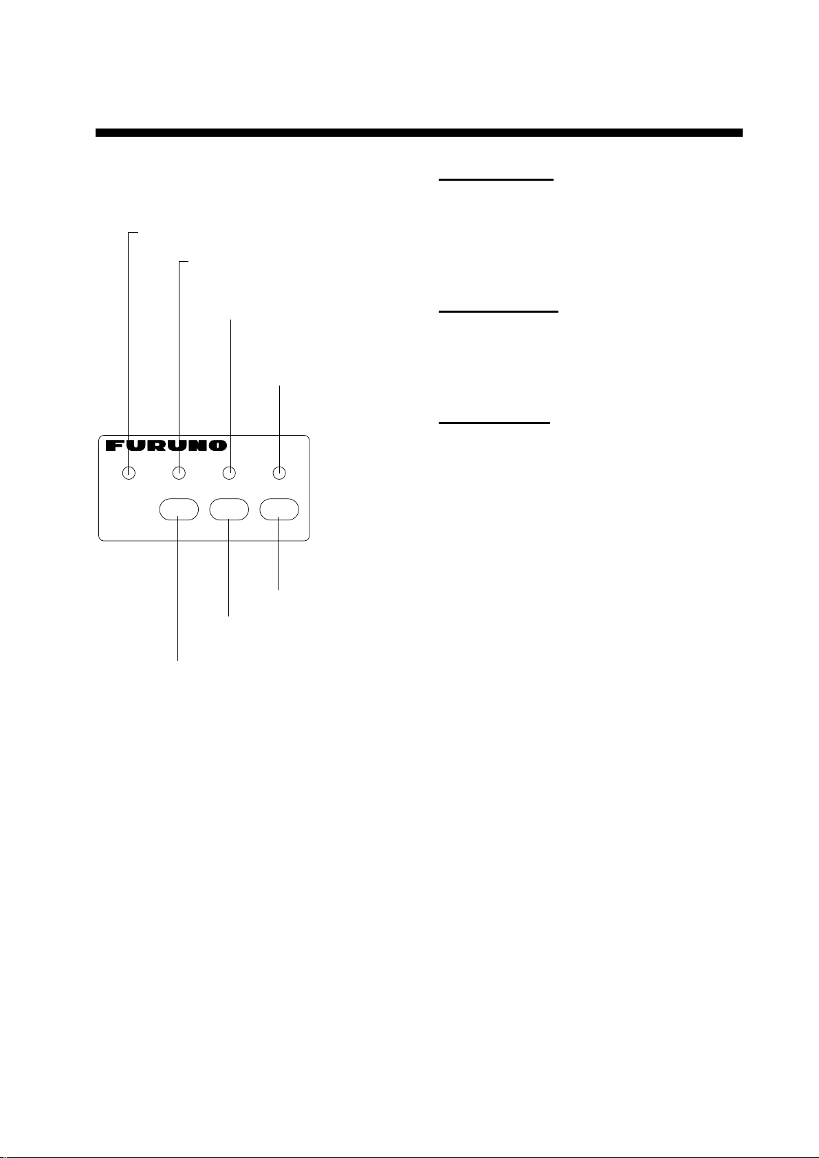
1.1 Controls and Indications
On: Auto correction is on.
Off: Auto correction is off.
On: True heading is output.
Off: Magnetic heading is output.
Off: Normal
Blinking: Correcting the deviation.
(For installation)
On: Normal
Off or blinking: Error
CALBTRUE STATUSAUTO
CALIBRATION
ADJDAMPAUTO
Program version
The program version, denoted by the LEDs
in binary notation, is shown. For example,
the LED state shown on the next page
means the program version is “1.03”.
ROM, RAM check
AUTO LED lights: ROM is normal.
TRUE LED lights: RAM is normal.
(CALB and STATUS LEDs are always lit.)
Deviation status
All LEDs blink twice when the calibration is
completed.
After the diagnostic tests are completed;
• C-500 outputs heading data and the
STATUS LED lights immediately.
Corrects the heading.
Smoothes the heading data to output.
Turns deviation corrections on and off.
Front panel of sensor
1.2 Turning the Power On/Off
Power to the sensor may be turned on or off
at the mains switchboard.
Turn the mains switch on.
The sensor checks the program version,
LED, ROM, RAM and deviation status in that
order for proper operation.
• PG-500 calculates the rate sensor offset.
The STATUS LED blinks during the
calculation, which takes about two minutes.
When the STATUS LED lights, bearing is
reliable.
Note: Confirm that the STATUS LED is lit
(not blinking) before leaving port.
1
Page 8
1. OPERATION
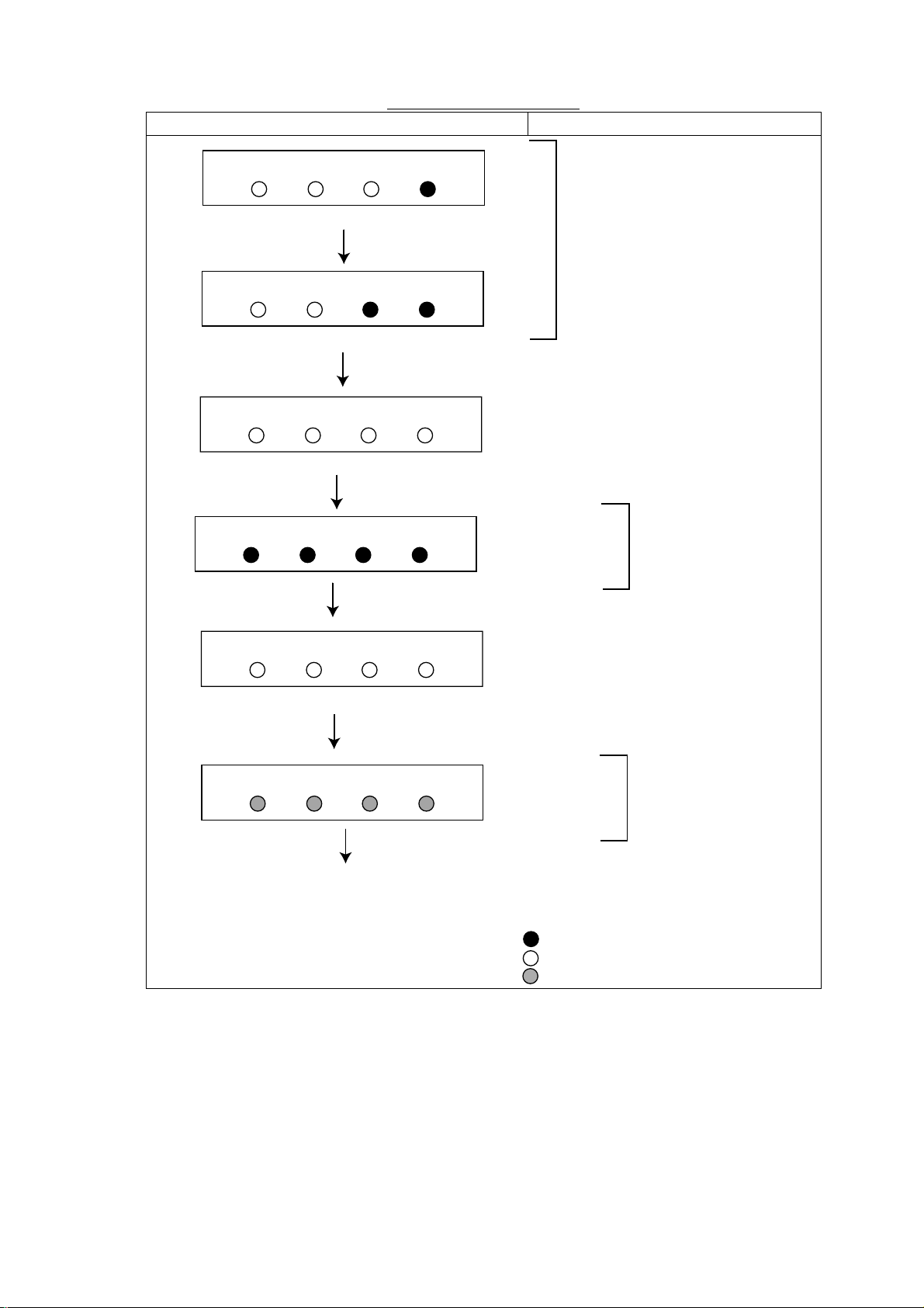
Sequence of Start up test
LED Sequence Test name
AUTO TRUE CALB STATUS
8421
0.5 seconds
AUTO TRUE CALB STATUS
8421
0.5 seconds
AUTO TRUE CALB STATUS
8421
0.5 seconds
AUTO TRUE CALB STATUS
0.5 seconds
AUTO TRUE CALB STATUS
Program V ersion No.
All LEDs go off.
ROM, RAM check
All LEDs go off.
8421
0.5 seconds
AUTO TRUE CALB STATUS
Twice
Deviation status
0.5 seconds
Normal operation
: On
: Off
: Blinking
2
Page 9

1. OPERATION
1.3 Automatic Distortion Compensation
Magnetic field distortion on your vessel has
been compensated at the installation. When
the magnetic field distortion changes, it can
be compensated automatically as follows.
Note: This function is only effective after
compensating for magnetic field
distortion. (Refer to page 10.)
1. Press the [AUTO] key more than two
seconds to light the AUTO LED.
AUTO
The STATUS LED lights during the automatic
distortion compensation functions.
2. To cancel automatic compensation, press
the [AUTO] key more than two seconds,
to turn off the AUTO LED.
Note 1: Do not conduct this procedure when
your boat is near a steel ship or iron
bridge, since they affect sensor
performance.
Note 2: Correct distortion whenever you feel
heading error is excessive.
TRUE CALB STATUS
:On
:Off
:State depends on settings
Auto compensation
1.4 Damping Control
The damping control determines how
sensitively the sensor responds to change of
ship’s heading. When the damping value is
large, the sensor responds smoothly but a
small boat may wander after the turning. Use
a small damping value as possible.
Note: When connecting with the autopilot
NAVpilot-500, use the default damping
setting (PG-500: damping 1, C-500:
damping 2).
1. Press the [DAMP] key more than two
seconds.
All LEDs go off, and then the current damping
setting is shown by the LEDs.
2. Press the [DAMP] key to change the
damping setting in the sequence of
damping 1→2→3→4→1→…
AUTO
TRUE CALB
STATUS
Damping 1
Damping 2
Damping 3
Damping 4
: On
: Off
Damping LED state
If three seconds passes with no operation,
the damping setting is fixed, and the
damping control mode is terminated.
3
Page 10

1. OPERATION
1.5 Selecti ng O ut put Data Format
The sensor can output true or magnetic
heading. The default setting is magnetic, in
AD-10 format.
CAUTION
Turn off the autopilot before selecting
output data format.
The autopilot may turn the rudder suddenly.
To output true heading, do the following:
1. Connect Furuno GPS Navigator which
can output data sentence RMC or VTG.
2. Set up magnetic variation (manual or
automatic) at the GPS Navigator.
When RMC or VTG is input to the sensor, the
TRUE LED lights and then true heading is
output to other equipment.
4. To return to magnetic heading output,
disconnect the GPS Navigator.
Note 1: If the TRUE LED does not light
within 90 seconds, check the
navigator setting and cable
connection.
Note 2: If the sensor stops receiving
magnetic variation data while
outputting true heading, the TRUE
LED stops lighting and blinks. The
last-used variation data is used.
Note 3: Magnetic variation cannot be
corrected manually at the sensor.
Therefore, if you desire true heading
output but do not have a navigation
aid, you may enter appropriate
variation as shown in 3.4 Heading
Alignment on page 11. HDM
sentence, however, cannot be
changed to true heading. For HDG
sentence, it can be changed to true
heading at the equipment connected,
by using the magnetic heading and
magnetic variation data in the
sentence.
4
Page 11

2. MAINTENANCE & TROUBLESHOOTING
2.1 Maintenance
Regular maintenance is important to maintain intended performance over a long period.
Regularly check the following:
• Clean the component with a soft cloth. Do not use chemical cleaners; they can remove paint
and markings.
• Make sure all connections are tight.
• Check the ground terminal for corrosion. Clean if necessary.
2.2 Troubleshooting
The table below provides simple troubleshooting procedures which the user can follow to
restore normal operation. If normal operation cannot be restored do not check inside the
equipment; there are no user-serviceable parts inside. Any repair work should be referred to a
qualified technician.
Symptom Remedy
• Check power connector.
Unit cannot be powered.
LEDs do not light.
Heading data error.
The heading data is not output to
external equipment.
• Check the ship’s mains.
• Check the fuse.
• Check power connector.
• Do the diagnostic test.
(Refer to the next page.)
• Do the diagnostic test.
(Refer to the next page.)
• Check connections.
• Do the diagnostic test.
(Refer to the next page.)
5
Page 12

MAINTENANCE & TROUBLESHOOTING
2.3 Diagnostic Test
This equipment has a diagnostic test which
checks the LED, key operation, ROM, RAM,
EEPROM, magnetic sensor, rate sensor
(PG-500 only) and loop back for proper
operation. Do this test after dismounting the
sensor.
1. Disconnect the power cable from the
equipment.
2. While pressing the [AUTO] and [DAMP]
keys together, reattach the power cable.
3. Release the [AUTO] and [DAMP] keys
when the AUTO LED lights.
Then, the test is executed in the sequence
shown in the right column.
*1: If STATUS LED does not light (NG),
this test cannot be carried out. Contact
your dealer.
Also, if the sensor is not turned within
one minute after the EEPROM test,
the test is carried out with the “Mag
sensor” is NG.
*2: The loop back test requires a special
test connector.
It is skipped when the test connector
is not connected.
Start
AUTO LED
:
OK
TRUE LED
OK
:
CALIB
LED: OK
STATUS
LED: OK
All LEDs
blink twice.
AUTO lights
automatically.
AUTO TRUE CALB
STATUS
Press the [AUTO] key.
AUTO key
: OK
Press the [DAMP] key.
DAMP key
: OK
Press the [ADJ] key.
ADJ key
: OK
Press the [AUTO] and [DAMP] keys together again.
All LEDs
go off.
ROM:
OK
RAM:
OK
EEPROM
: OK
Turn the sensor more than 180 until STATUS LED lights.*1
Mag.
sensor: OK
All LEDs
go off.
Rate
OK
sensor:
Loop back
OK*2
:
All LEDs
go off.
: On (normal)
Normal operation
: Off (error)
(PG-500 only)
: Blink
Sequence of diagnostic test
6
Page 13

2.4 Error Status
When error is detected, all LEDs go off and
then the STATUS LED blinks or goes off
depending on error type as shown in the
table below.
LED status Meaning Remarks
STATUS LED
blinks slowly.
STATUS LED
blinks quickly.
STATUS LED
goes off.
Magnetic
deviation error
EEPROM error
Other than the
above.
Appropriate LED
blinks.
CALIB LED:
Rate sensor
error
TRUE: Cable of
the magnetic
sensor is cut.
2. MAINTENANCE & TROUBLESHOOTING
2.5 Clearing the Memory
The memory can be cleared to start afresh
with default settings.
1. Disconnect the power cable from the
equipment.
2. Reattach the cable while pressing the
[AUTO] and [ADJ] keys together.
After the memory has been cleared, the
sensor returns to the normal mode.
If the memory could not be cleared, the
STATUS LED blinks quickly.
7
Page 14

3. INSTALLATION
3.1 Mounting
This sensor must be mounted indoors on the
horizontal plane.
When selecting a mounting location, keep in
mind the following points:
• Vibration at the mounting location should
be minimal.
• Install the sensor as far as possible from
power cables and ferrous materials.
• Install the sensor near the ship's center of
gravity.
• Align the bow mark with the ship's bow on
the fore-and-aft-line.
Fix the sensor by using tapping screws
(supplied).
Ship's bow
Fixing hole
( 4.5 mm)
This line should be at right
angles to the fore and aft line.
Bow mark
1
6
141
152
3
0
5
5.5
Material: Brass
All dimensions in mm.
For added support, use M4 nuts, bolts
and washers instead of tapping screws.
Secure sufficient clearance around the
sensor for maintenance and checking.
Mounting the sensor
Note: Do not overtighten the screws or bolts;
the sensor may crack.
8
Page 15

3. INSTALLATION
3.2 Connections
Connect cables as shown below.
Leave sufficient slack in cables for
maintenance and checking ease. If cables
run outside the bridge, run them through
conduit to protect them from corrosion.
Note: The NMEA port (the mid position) can
receive and send data. However,
when connecting with the
NAVpilot-500 or RD-30, the NMEA
port is for output only.
12-24 VDC: MJ-A7SPF0009-020 (supplied)
NAVpilot-500: MJ-A7SPF0010-100
(supplied with the NAVpilot-500)
Ground cable
(Local supply)
Grounding
12-24 VDC
+
BOW
NMEA
-
AD10
Grounding
Ground the equipment as follows to prevent
loss of sensitivity:
• The ground wire should be as short as
possible.
• The ground wire should be about 1.25 sq
and not contain steel.
• Use only a closed-end lug.
Pan head screw
Spring washer
Crimp-on lug
(closed,
local supply)
Ground term inal, sect ional view
Flat washer
Ground wire
(1.25 sq,
local supply)
Seal washer
12-24 VDC
or
Processor Unit
of NAVpilot-500
MJ-A6SPF0003-050 (option)
Ground
terminal
External equipment
(Current Indicator, etc.)
MJ-A6SPF0007-100
(supplied as installation material)
Sensor, top view
External equipment
(Radar, etc.)
Connection of external equipment
NMEA: Digital interface NMEA format
input/output terminal.
Output: HDG, HDT, HDM (Magnetic
Heading)
Input*: RMC or VTG
AD-10: Outputs heading information in
AD-10 format.
12-24VDC: Power input, Digital interface
NMEA format input/output terminal
Output: HDG, HDT, HDM (Magnetic
Input*: RMC or VTG
*Only one port can be for Input.
Note: Cover unused connector(s) with the
Heading)
rubber cap (supplied) to prevent
ingress of water.
9
Page 16

3. INSTALLATION
3.3 Correcting Magnetic Field Distortion
The magnetic field around the sensor is
subject to change with the ship structure,
engines, electronic equipment or any ferrous
materials in the vicinity.
The equipment contains an automatic
magnetic field distortion correction facility.
Do the following to correct magnetic field
distortion on calm water.
1. Steer the boat clockwise or
counterclockwise in a circular course.
Take about two minutes to complete the
circle (at about 3 kt). While turning the
boat, go to step 2.
2 minutes for a circle
(at about 3 kt)
Note: Complete circle within 2 minutes,
otherwise large error may result.
2. Press [ADJ] and [DAMP] keys together
more than two seconds. The CALB LED
blinks.
AUTO TRUE CALB STATUS
: Blinking
: Off
light. Wait 30 seconds for the sensor to
return to normal operation, or press any
key for quick return.
AUTO TRUE CALB STATUS
: On
LED status at successful correction
Note 1: Do not turn off the power supply
during the correction. Data may be
corrupted.
Note 2: Continue turning the boat even if the
CALB LED status changes from
blinking to lighting. Keys are
inoperative when the CALB LED is
lighting.
Note 3: The sensor does not output heading
data during the correction.
4. Anchor the boat at the pier to check
sensor heading to a known point (for
example, lighthouse).
If there is error, see "3.4 Heading
Alignment.”
If some LED does not light, change
sensor location and repeat step 2
through 4.
If the correction failed, the LED status is
as shown below. This continues until you
press any key to clear the display.
(Turning off the power at switchboard will
not clear the LED display.) Try the
correction again.
AUTO TRUE CALB STATUS
LED status during compensation
Note: You can return to normal operation
at any time by pressing the
[DAMP] key.
3. Continue turning the boat in a circle
(three to five times) until a result is shown
with the LEDs.
When correction is successful, all LEDs
10
: Blinking
: Off
LED status, compensation failed
Page 17

3. INSTALLATION
3.4 Heading Alignment
Heading alignment is required when sensor
heading is different from actual heading.
This alignment must be done using magnetic
heading (default setting).
CAUTION
Turn off the autopilot before aligning
heading.
The autopilot may turn the rudder suddenly.
Procedure
1. Press the [ADJ] key more than two
seconds. All LEDs go off.
AUTO
TRUE CALB STATUS
: Off
AUTO
+1°
+2°
+3°
+4°
+5°
+6°
+7°
Repeat
TRUE CALB
STATUS
: On
: Off
LED state and pressing of [DAMP] key
When pressing the [ADJ] key, the above
sequence begins from the STATUS LED
side.
Note: Complete the next step within 10
seconds, otherwise normal operation
is restored.
2. Set difference between sensor heading
(output) and actual heading with the
[DAMP] key for “+” or [ADJ] key for “-”.
For example, the heading output by the
sensor is 70° and the actual heading is
75°. Therefore, the difference is +5°.
Press the [DAMP] key five times to set
+5°. Each time the [DAMP] key is
pressed, the LEDs light as shown below.
11
Page 18

3. INSTALLATION
3.5 Setting O ut put Data
Setting output interval
The default setting is 200 ms.
Refer to the table shown on the next page
for proper setting.
1. Disconnect the power connector from the
sensor.
2. Reattach the connector to the sensor
while pressing the [DAMP] key. The
equipment is powered on, and the
current output interval is shown by the
LEDs.
AUTO TRUE CALB
1 s
200 ms
100 ms
25 ms
LED state and output inte r val
If step 2 was not completed satisfactorily, the
STATUS LED blinks quickly. Try step 2
again.
3. Press the [DAMP] key to change interval.
The sensor returns to the normal mode if
there is no operation for three seconds.
Setting the output sentence(s)
STATUS
: On
: Off
AUTO TRUE CALB STATUS
HDT HDG
:On (current setting)
:Off
: True heading
HDT
: Magnetic heading
HDM
: Magnetic heading & Magnetic variation value
HDG
AUTO LED has no function.
HDM
(sentence)
LED and output sentence
3. Press key corresponding to sentence to
output.
Sentence Key
HDT [AUTO]
HDG [DAMP]
HDM [ADJ]
To cancel output, press the same key again.
Note 1: Several sentences may be
output simultaneously. However,
delay may result when the output
interval is 100 ms or 200 ms.
Note 2: "HDT" outputs true heading data.
However, if variation data is not
input from the GPS navigator,
magnetic bearing will be output.
The equipment returns to the normal mode if
there is no operation for three seconds.
Select which type(s) of heading data to
output. The default setting is HDG.
1. Disconnect the power connector from the
sensor.
2. Reattach the connector to the sensor
while pressing the [ADJ] key. The
equipment is powered on, and LED(s)
light to show which output sentence(s) is
being output.
12
Page 19

3. INSTALLATION
3.6 Setting Ba ud Rate
Set the baud rate of external equipment.
The default setting is 4800 bps.
When connecting with the NAVpilot-500, use
the default setting (4800 bps).
1. Disconnect the power connector from the
sensor.
2. Reattach the connector to the sensor
while pressing the [AUTO] key. The
sensor is powered on, and the current
baud rate is shown by the LEDs.
3. Press the [AUTO] key to change the
baud rate as appropriate.
AUTO TRUE CALB
4800
9600
19200
38400
LED and baud rate
STATUS
: On
: Off
Relation baud ra te and output interval
Baud rate Output interval Available sentences
25 No output
4800
9600
19200
38400
Note: When an error message occurs, the above
sentences may be changed
100
200
1000
25
100
200
1000
25
100
200
1000
25
100
200
1000
Up to two sentences can
be output.
Up to three sentenc es can
be output.
HDT or HDM
Up to three sentenc es can
be output.
Up to two sentences can
be output.
Up to three sentenc es can
be output.
.
If baud rate could not be set, the STATUS
LED blinks quickly. Try again.
The sensor returns to the normal mode if
there is no operation for three seconds.
13
Page 20

SPECIFICATIONS OF INTEGRATED HEADING SENSOR
PG-500
1 GENERAL
1.1 Heading Accuracy 1.0°rms (horizontal)
1.5°rms (within 30°)
1.2 Display resolution 0.1°
1.3 Follow-up 30°/s rate-of turn
1.4 I/O Port Input: 1 port
Output: 2 ports (one port drives 3 outputs)
1.5 Interface
Output FURUNO AD-10 format
IEC 61162-1 (NMEA 018 3 Ver2.0)
HDG, HDT, HDM
Input IEC 61162-1 (NMEA 018 3 Ver1.5/2.0)
RMC, VTG
1.6 Data Update AD-10 formatted: 25 ms
IEC 61162-1 (NMEA 018 3): 100ms, 200 ms or 1 s selected
2 POWER SUPPLY
12-24 VDC: 0.12-0.03 A
3 ENVIRONMENTAL CONDITION
3.1 Ambient Te mper ature -15°C to +55°C
3.2 Relative H umidity 95% at 40°C
3.3 Waterproof IP5 (IEC 60529), CFR-46 (USCG standard)
3.4 Vibration IEC 60945
4 COLOR
N3.0
SP - 1 E7255S01B
Page 21

PACKING LIST
C7255‑Z01‑B
A-1
PG‑500/C‑500
64AV‑X‑9851 ‑1
1/1
NAME
OUTLINE
DESCRIPTION/CODE№
ユニット UNIT
ハイブリッドヘディングセンサー
INTEGRATEDHEADINGSENSOR
ヘディング゙センサー
FLUXGATEHEADINGSENSOR
PG‑500
000‑040‑467
C‑500
000‑040‑468
予備品 SPAREPARTS SP64‑01301
ヒューズ
FUSE
FGMB1A125V
000‑114‑805
工事材料 INSTALLATIONMATERIALS CP64‑02101
+トラスタッピンネジ
+TAPPINGSCREW
4X16SUS3041シュ
000‑802‑080
その他工材 OTHERINSTALLATIONMATERIALS
ケーブル組品MJ
MJ‑A6SPF0007‑100
Q'TY
1
(*1)
1
(*1)
2
2
CABLEASSY.
ケーブル組品MJ
CABLEASSY.
1
000‑125‑237
MJ‑A7SPF0009‑020
1
000‑145‑612
(*1)のユニットは仕様により決定されます。
(*1)UNITHASBEENDETERMINEDBYSPECIFICATION.
(略図の寸法は、参考値です。DIMENSIONSINDRAWINGFORREFERENCEONLY.)
Page 22

Y.Hatai
Page 23

1
Y. Hatai
23
A
ヘディングセンサー
HEADING SENSOR
PG‑500/C‑500
AD10
AD10DATAH
AD10DATAC
AD10CLKH
AD10CLKC
IEC61162
B
NMEA0183 OUT
NMEA0183 IN
12‑24 VDC
NMEA
TDA
TDB
RDH
RDC
12‑24 VDC
TDA
TDB
RDH
RDC
GND
GND
(+)
(‑)
GND
NC
NC
MJ‑A6SPFD
1
2
3
4
5
6
MJ‑A6SPFD
1
2
3
4
5
6
MJ‑A7SPFD
1
2
3
4
5
6
7
*3
P
P
*3
P
P
P
P
MJ‑A6SPF0007,10m,φ6
シロ
クロ
キ
ミドリ
MJ‑A6SPF0003,5m,φ6
シロ
WHT
クロ
BLK
キ
YEL
ミドリ
GRN
*3
シロ WHT
アオ BLU
キ YEL
ミドリ GRN
アカ
RED
クロ BLK
WHT
BLK
YEL
GRN
*2
MJ‑A7SPF0009, 2m,φ7
1A
1A
*3
MJ‑A6SPFD
P
P
1
DATAH
2
DATAC
3
CLKH
4
CLKC
5
NC
6
GND
NAVnet シリーズ
NAVnet series
航法装置
NAV. EQUIPMENT
NAVnet シリーズ
NAVnet series
オートパイロット
AUTOPILOT
航法装置
NAV. EQUIPMENT
12‑24 VDC
オートパイロット
レーダー
潮流計
AUTOPILOT
RADAR
CURRENT INDICATOR
*4
C
D
*1
GND
IV‑1.25SQ.
注記
*1)造船所手配。
*2)オプション。
*3)工場にて取付済み。
*4)NAVpilot‑500を接続する場合、相互結線図はNAVpilot‑500の装備要領書を参照(PG‑500のみ)。
NOTE
*1. SHIPYARD SUPPLY.
*2. OPTION.
*3. FITTED AT FACTORY.
*4. WHEN NAVpilot‑500 IS CONNECTED TO PG‑500, REFER TO INTERCONNECTION DIAGRAM IN INSTALLATION MANUAL OF NAVpilot‑500.
DRAWN
Aug. 27, '04
CHECKED
APPROVED
SCALE
DWG.No.
E. MIYOSHI
TAKAHASHI.T
MASS
kg
C7255‑C01‑ C
TITLE
PG‑500/C‑500
名称
ハイブリッドヘディングセンサー/ヘディングセンサー
相互結線図
NAME
INTEGRATED HEADING SENSOR/HEADING SENSOR
INTERCONNECTION DIAGRAM
Page 24

9-52 Ashihara-cho,9-52 Ashihara-cho,
A
A
*
00014725601
**00014725601
*
*
00014725601
**00014725601
*
*
OME
72550
C
20
**OME
72550
C
20
**OME
72550
C
20
**OME
72550
C
20
*
Nishinomiya 662-8580, JAPANNishinomiya 662-8580, JAPAN
Telephone :Telephone : 0798-65-21110798-65-2111
FaxFax 0798-65-42000798-65-4200
ll rights reserved.
ll rights reserved.
::
Printed in JapanPrinted in Japan
Pub. No.Pub. No. OME-72550OME-72550
Your Local Agent/DealerYour Local Agent/Dealer
IRST EDITION :
IRST EDITION : APRAPR.. 20032003
C2C2 :: OCTOCT.. 13, 200413, 2004
(( YOTAYOTA ))
PG-500/C-500PG-500/C-500
* 0 0 0 1 4 7 2 5 6 0 1 ** 0 0 0 1 4 7 2 5 6 0 1 *
* O M E 7 2 5 5 0 C 2 0 ** O M E 7 2 5 5 0 C 2 0 *
 Loading...