

Page 1

BRIDGE ALARM MONITORING & WATCH SAFETY SYSTEM
BR-2000
Page 2

Contents
1 INTRODUCTION....................................................................................3
2 ALARM MONITORING SYSTEM (AMS)...............................................4
2.1 Multipurpose Screen......................................................................... 4
2.1.1 Conning page................................................................................ 4
2.1.2 Alarm page.................................................................................... 6
2.1.3 Function page...............................................................................7
2.2 Alarms................................................................................................ 9
2.2.1 General.........................................................................................9
2.2.2 Alarm categories .........................................................................10
2.2.2.1 Group alarms ...........................................................................10
2.2.2.2 Detailed alarms........................................................................10
2.2.3 Alarm types.................................................................................10
2.2.3.1 Event alarm.............................................................................. 10
2.2.3.2 State alarm............................................................................... 10
2.3 Alarm / Conning control panel.......................................................11
3 WATCH SAFETY SYSTEM (WSS)......................................................12
3.1 Description of system's function...................................................12
3.2 Timer Control panel ........................................................................13
3.3 Bridge Control panel.......................................................................13
3.4 Cabin Control panel........................................................................ 15
3.5 Remote reset push button..............................................................15
4 FLOW CHART OF AMWSS.................................................................16
Page 3
1. INTRODUCTION
Alarm Monitoring and Watch Safety System (AMWSS) is intended to centralize all bridge and other
important alarms to one posit i on on the bridge and to monitor watchkeepers activity as well as to ensure
his well-bein g.
The system operation is divided in t wo indepe ndent Programmab le Log ic Com puter (PLC) sy st ems, one
taking care of Alarm Monitoring and the second one to take care of Watch Safety Sy st em. The PLC for
Watch Safety System is also generating an independent "Off course" monitoring, "Gyro mismatch" and
"Magnetic compass compare" functio ns.
Both systems are described in the drawing below.
Fig. 1 Block Diagram
Page 4

2. ALARM MONITORING SYSTEM (AMS)
The basic feature of alarm mo nit oring PLC is to collect all bridge and other imp ortant alarms and display
them on the multipurpose screen. When the full redundancy and greater flexibility of dis play is requ ired
then two independent comp ut ers and screens are optionally inst alled.
2.1 Conning/Alarm Display
Two multipurpose screens are used to display either the conning information or the alarm information.
Conning and the alarm dis plays are processed in "Display Cont rol Computers".
In some cases depending on redundancy requirements the other multipurpose screen can be replaced
by an other integrated system's screen equipped with change-over switch - e.g. ECDIS-screen.
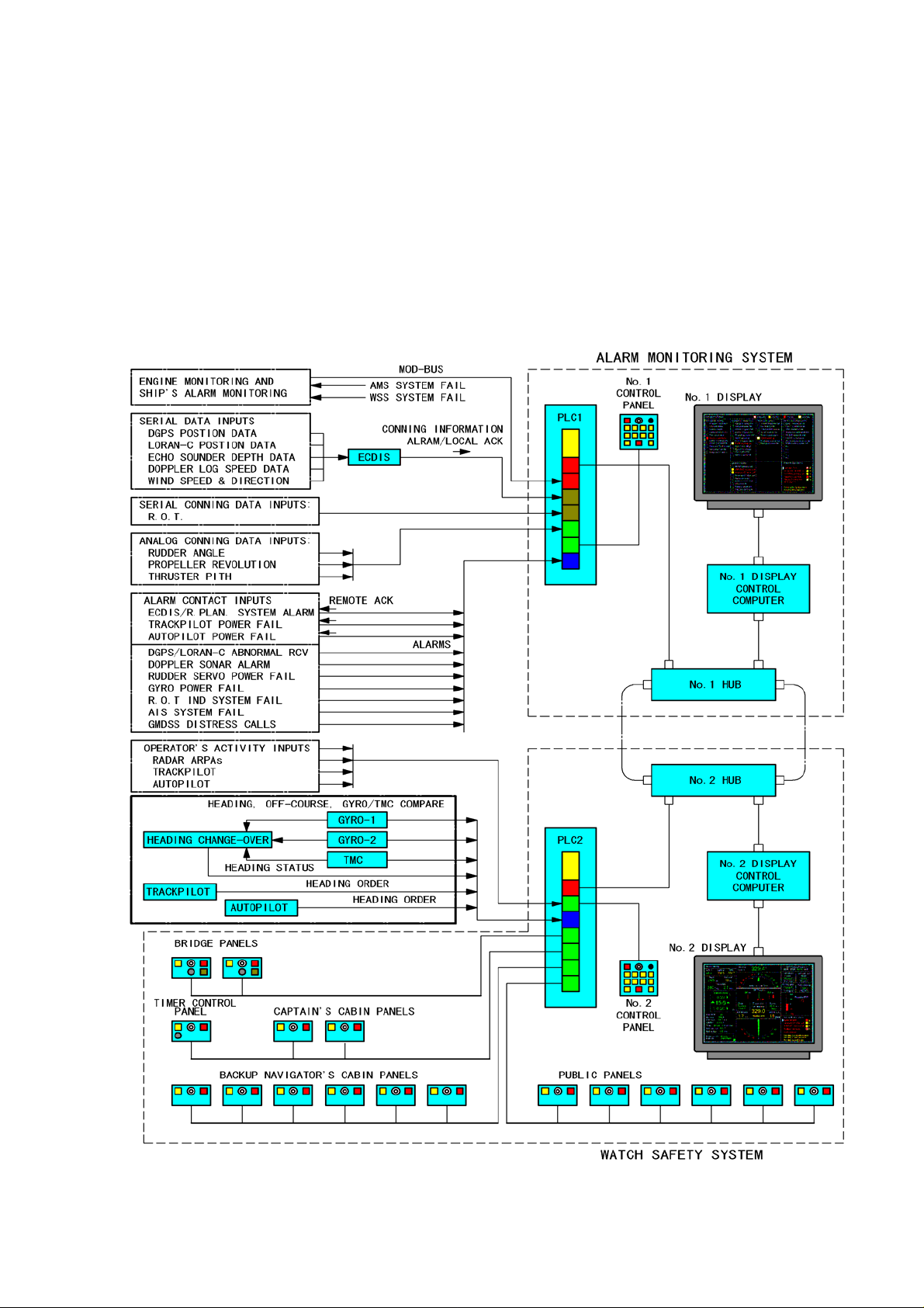
2.1.1 Conning page
Conning pages can be configured up to two different pages (i.e. main and harbour conning). Conning
pages are selected on Conning Display Control panel.
The conning information is mainly received from following external sy st ems:
- ECDIS processor waypoi nt information
- Track pilot heading order, steering mode and Off-Track information*
- Autopilot heading order and steering mode information*
- Gyrocompasses Headin g information*
- Magnetic Compass with T M C Heading information*
- Heading Change-over se l ected heading and status infor mation*
- Rate Of Turn information
- Rudder Angle Indication
- Propulsion infor mation
- Thruster Pitch Information
- Echo Sounder Depth and Set Limit information**
- Wind Indicator Speed and Bearing information**
- Dual-axis Speed Log information**
- Machinery information from DCS
*: Information applied through the Watch Safety Electroni c unit.
**: Information applied through t he ECDIS.
The latest five "non-acknowledged" alarms are displayed in the lower right corner of the display.
The following Watch Safety information is displayed in the low er left corner of the display.
- Bridge Watch set condition; “Enable” or “Disabl e”
- Back-up navigator select ion
- Timer bar indicatio n
Examples of Main Conn ing and Harbour Conning pages are shown in figures on next pa ge.
Page 5
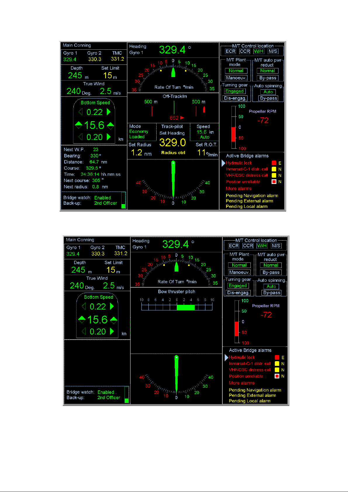
Fig. 2 Main Conning Page
Fig. 3 Harbour Conning Page
Page 6

2.1.2 Alarm page
Three alarm pages are availab le as b elow.
1) Navigation Alarm page:
It consists of four windows indicating navigation related alarm. (See Fig. 4)
a) Navigation Safety: Nav iga tion alarms requiring great attention for safety.
b) Navigation Equipment: Navigation sensor system a l arms.
c) GMDSS alarms: It alert s w hen any distress call received.
d) ECDIS alarms: Actual ECDIS alarms. Important alarms are transferred to the Navigation
Safety and Navigation Equipment windows for navigator’s attention; e.g. Waypoint Approach,
Off-track, Depth below limit, Posit ion u n rel iable, No speed available, No course availabl e.
2) External Alarm:
It consists of several windows indicating external alarms (Engine, Cargo, Steering Gears, General
Alarms, etc.), which are applied from Machinery/Cargo DCS. (See F ig. 5)
3) Local Alarm:
This page is prepared for the navigation equipments, which have no own visual display. (Track pilot,
Autopilot) The alarms generated in the AMWSS itself are also displayed on this page. (See Fi g. 6.)
Alarms are displayed and processed in different priorities for the identification of alarm importance.
Priorities are as following s:
- Emergency alarms - alarms which indicate that immediate danger to human life, or to the ship
and its machinery exists and t hat immediate action must be taken.
- Distress, urgency and s afety alarm s - alarms, which indicate that a caller is in d istress or h as
an urgent message to transmit.
- Primary alarms - alarms, which ind icate a con dition that require s, prompt att ention to prev ent an
emergency condition.
- Secondary alarms - all other alarms.
Each alarm is associated with coloured marker showing int o which priority the alarm belongs.
- Emergency alarms – red marker
- Distress, urgency and safety alar m s – y e llow ma r ker
- Primary alarms – white marker surrounded by red stripe
- Secondary alarms – red marker surrounded by white stripe
The latest five active alarms are displayed in the alarm list in the lower right corner of the display. The
rest of the active alarms are displayed on alarm pages. Alarms in the active alarm list are shown in
order of priority and occurrence.
Non-acknowledged alarms are indicated with a flashing red text and marker and buzzer.
Acknowledged but pending alarms are distinguished from other alarms by steady non-flashing yellow
alarm text on alarm page.
Yellow text below alarm list e.g. Pending navigation alarm, means that there is at least one pending
alarm on alarm page.
Page 7

Fig. 4 Navigation Alarm
Fig. 5 External
Alarm
Fig. 6 Local Alarm
Page 8

2.1.3 Function page
Function page is used to set some operation and installat ion p arameters.
- Alarm History
- Selection of Back-up nav i gat or*
- Installation parameters**
- Selection of over-head pa nel display presentation (option al feature)
*: not accessible to other persons than captain or othe r aut horized person.
See the leaflet “HOW TO SELECT BACK-UP NAVIGATOR”.
**: not accessible to other persons than service engineers.
See the leaflet “INSTALLATION PARAMETER SETTING”
How to print out the History Alarm:
1) Press the FUNC SET key. A menu window will app ear on t he
screen. The menu contains a cursor (blue tr iangle) and three items.
2) Move the cursor to the “Alarm History” posit ion with the MOVE
UP and MOVE DO WN key s , and press t he ENTER–key. The printer,
connected to the display cont rol computer print a alarm log table.
3) Press the FUNC SET button aga in. The menu window is closed.
Page 9

2.2 Alarms
2.2.1 General
In the practice, the general rule for inte gratio n of dif f erent brid ge eq uipm ent is that any equip ment , wh ich
can sound or indicate any alarm o n t he bridge, is to be included in t he A larm Monitoring system.
Following navigation eq ui pment is to be integrated in the Alarm Monitoring system:
- ARPA radars (CPA/TCPA alarm)
- ECDIS
- Track Co nt rol System and Headin g C ontrol system
- Steering system and steering gear
- Position Fixing equip ment
- Echo sounder
- Speed log
- Navigation light controls
- Bridge power supply and dist ribution box
- Watch safety system
Other bridge equipment or systems, which can be in cluded in the AMS:
- Propulsion system
- Engine automation
- GMDSS and Navtex
- Fire detection
- Cargo monitoring alarms
- Water tight doors
- Hospital call et c .
Following alarms are to be inc luded in the centralized Alarm Monitoring System:
- CPA/TCPA
- Shallow depth (Depth be l ow limit)
- Waypoint approach
- Off course
- Off track
- Steering alarms
- Navigation light fai lure
- Gyro compass failure
- Rate Of Turn indicator failure
- Watch saf et y failure
- Failure of any power supply to the distribution panels
- Position fix in accurate
- Lost of heading input
- Lost of log input
- System failure
- Gyro mismatch
Page 10

2.2.2 Alarm categories
2.2.2.1 Group alarms
Alarms are arranged in groups, in order to reduce the quantity of information presented to the operator.
Such alarm groups can be e.g. fire, watertight doors, and bilge water etc alarms. Group alarm can be
assigned to any priority.
The following alarms are not to be grouped:
- Emergency alarms
- Alarms associated with faults requiring speed or power reduction or the automatic shutdown of
propulsion machinery
- Steering gear alarms
2.2.2.2 Detailed alarms
There is a common rule for understanding when there is a need for more detailed information of
individual alarm from the external system. That is that when the situation may lead to a danger for the
ship or human life, reduction of s peed or maneuverability, more information of alarm is to be available.
2.2.3 Alarm types
2.2.3.1 Event alarm
- Event alarm is an alarm, which is normally used only to alert operator, but does not require any
alarm acknowledge m ent .
- This type of alarm may activate sound alarm in the external system, or may be only a visual
alarm indication.
- Alarm indication in the external system will disappear by itself.
- AMS has the option (programmed i nside AMS) to release the alarm buzzer in AMS.
2.2.3.2 State alarm
- State alar m is an a larm, which normally requires operator’s acknowledgement.
- Sound alarm is norma lly released in the external equipment.
- Sound alarm of external equipment can be acknowledged at AMS provided there is a two-way
alarm acknowledge ha ndshake between external system and AMS.
- AMS will release the alarm and transmits acknowledgement of this alarm, if acknowledged in
AMS.
- External system should remove local sou nd alarm.
- Acknowledge from AM S s hould not remov e the st ate of the alar m in the ext er nal sy ste m, as lon g
the alarm condition persists.
- AMS will display pending alarm as long as the alarm condition persists in external system.
Page 11

2.3 Alarm / Conning control panel
Alarm / Conning control p anel is used to manage bridge alarms and screen presentation.
System Alarm will
illuminate in case the
Alarm monitoring
system is failing
Buzzer will release the
sound whenever a
bridge alarm is detected
Dimmer will adjust the
illumination of pushbuttons except for
indication of alarms
Function push
button will enable
changes on the
display (I.e. the
selection of back up
navigator etc.)
Enter push button will
enable changes on the
display
Move Up will move
the cursor to next
row up on the
display
Move Down will move
the cursor to next row
down on the display
Alarm Pages will
select the
Navigation,
External and Local
alarm page for the
display
2.3.1 Alarm Acknowledgement
The latest five "non-acknowledged" alarms are displayed
in the lower right corner of the display.
1) Move the triangle cursor to an acknowledge alarm
with the MOVE UP and MO VE DOWN keys, and
press the ENTER key. The acknowledge alarm will
disappeared from this window s and t he text color
of the acknowledged alar m will change from red
flashing to yellow stable in the alarm page.
2) Audible alarm will also stop at the same time.
Alarm Acknowledge
push button will
acknowledge bridg e
alarm
Conning Pages will
select the Main and
Harbour conning
pages for the display
Page 12

3. WATCH SAFETY SYSTEM (WSS)
Watch safety system is intended to monitor watchkeeper’s activity as well as to ensure his well being
and awareness.
The system incorporates the following functions:
- Monitoring of operator's activity in different navigat ion equipment.
- Transfer of watch safety alarm to specified locations, in case the operator fails to respond in
given time period to watch safety alarm.
- Transfer of "non-acknowledged" alarms to spec ified locations on board.
In addition to watch safety mon itori ng, the system performs also the fo ll owing monitoring func t io ns:
- Gyro mismatch
- Magnetic compass difference alarm
- Independent "Off-course" alarm (independent from the automatic steering device).
3.1 Description of system's function
The system is such that, at a predetermined time, the watchkeeper receives warning that he must
indicate his well-being by accepting the warning.
The time interval between warnings is adjustable up t o a max i mu m o f 12
minutes (3, 6, 9, and 12 min).
It is possible to acknow ledge t he warnin g at the navigat ion wor kstation and at other ap propriat e locat ions
on the bridge where an effective lookout may be kept. Acknowledgement of any alarm resets
automatically the time interval between warnings. Manual adjustment of main navigation equipment
controls is also used for this purpose.
In the event that the watchkeeper fails to respond and accept the warning within 30 seconds, or if any
alarm has not been acknowledged on the bridge within 60 seconds, the system immediately initiates a
watch alarm to warn the master and the appointed back-up navigator through a fixed installation.
Manual initiation of the watch alarm from the bridge i s also possible at any time.
The system is designed and arranged so that only the ship's captain has access for enabling and
disabling it. Time interval is set fro m ti mer co nt rol panel in captain’ s cabin.
Acknowledgement o f the watch alarm is only possi ble on the bridge.
Following control pane ls are included in the Watch Safety Sy st em:
- Timer set-up panel in the captain's cabin.
- Two Bri dge Cont rol pane ls at ma in nav igati on wor kst ation. Control panels are used t o res et the
watch timer, but can also be used to call app ointed back-up navigation officer to bridge.
- Remote timer reset panels, located o n bridge w ings and the ch art t able. Push buttons are used
to reset the watch timer.
- Up to 8 Cabin panels, locat ed in different cabins for navigating officers.
- Additional Cabin panel s, up to 8, for public places.
Control panels are presented in following pages.
Page 13

3.2 Timer Control panel
In captain's cabin
Enable Light will lit, whenever the
watch safety system is activated
from captain’s cabin
If the pushbutton is pressed, the
audible alarm sound and all lamps
are illuminated in the panel for
test purposes.
Alarm light will flash in case the
watchkeeper has f a i led to
acknowledge the watch period
warning in 30 seconds or if any
alarm has not been ackno wledged
on the bridge within 60 seconds
Timer Set switch will activate the
watch safety system
The time period is selected with
intervals of 3, 6, 9 and 12 minutes
Buzzer will sound in case the
watchkeeper has f a i led to
acknowledge the watch period
warning in 30 seconds or if any
alarm has not been ackno wledged
on the bridge within 60 seconds
The buzzer can only be
acknowledged on the bridge
Page 14

3.3 Bridge Control panel
Two panels at main navigat ion w o rkstation
Note The timer set-value
means the watch time
period set on Timer
Control Unit, located in
captain’s cabin
Enable Light will lit, whenever
the watch safety system is
activated from captain’s cabin
If the pushbutton is pressed, the
audible sound and all lamps are
illuminated in the panel for test
purposes.
Warni ng l ight will flash in case
the operator has not made any
action within timer set-value,
minus 30 seconds
Whenever the push-button is
pressed, the full timer value is
restored in the watch safety
system
Buzzer will sound intermitted
sound in case the operator
has not made any action
within timer set-value.
If there is no operator activity
within following 30 seconds,
alarm is released in captain’s
cabin, public areas and
back-up navigator’ s cabin
In case the operator fails to
respond to any bri dge alarm
within 60 seconds, alarm is
transferred to captain’s
cabin, public areas and
back-up navigator’ s cabin.
Dimmer potentiometer
will adjust the back light
value of pushbutt on
lamps. The warning
lamp light level is not
adjustable.
Call Back-up
pushbutton activates
the buzzer in the back
up navigator’s cabi n,
captain’ s cabin and
public areas.
Page 15

p
3.4 Cabin Control panel
In navigating of fi cers’ cabins and public plac es
Enable Light will lit,
whenever the watch
safety system is
activated from
captain’s cabin
If the pushbutto n is
pressed, the audible
alarm sound and all
lamps are illuminated
in the panel for test
purposes.
Buzzer will sound in case the
watch- keeper has failed to
acknowledge the watch period
warning in 30 seconds or if any
alarm has not been
acknowledged on the bridge
within 60 seconds
In case the bridge officer is
pressing Call Ba ck- up button,
buzzer will sound in back-up
navigator’s cabin, captain’s cabin
and public areas.
The buzzer can only be
acknowledged on the bridge.
Alarm light will flash in
case the watchkeeper has
failed to acknowledge the
watch period warning in
30 seconds or if any alarm
has not been
acknowledged on the
bridge within 60 seconds
In case the bridge officer
is pressing Call Back-up
button, alarm light is lit up
in back-up navigator’s
cabin, captain’s cabin and
ublic areas.
3.5 Remote reset push button
On bridge wings and the chart table
Reset push button will
reset the watch safety
system timer and
restores the timer
set-value interval
Page 16

4 FLOW CHART OF AMWSS
Following flow chart illustrates the principal functions of Alarm Monitoring and Watch Safety System.
Page 17

HOW TO SELECT BACK-UP NAVIGATOR
1) Press the FUNC SET key. A menu window will appear on the screen. The menu contains a cursor
(blue triangle) and three items. See Fig. a).
2) Press the keys in the following manner . (Password entry): See Fig. b).
EXTERNAL
ALARM
LOCAL
ALARM
3) Move the cursor to the “Backup Officer” position with the MOVE UP and MOVE DOWN keys, and
press the ENTER–key. A list of back-up officers appears on the menu window as Fi g. c).
a) Menu window b) Menu Window c) Backup Officer
(normal) (password entered)
selecting menu
4) Pull down the cursor to the w ant ed back-up
officer position, and press the ENTER key.
Backup officer indicat i on on the Conning
page changes to the select ed back-up officer.
5) Press the FUNC SET button aga in. The menu window is closed.
HARBOUR
CONNING
The selection of back-up navigator should be managed by the captain or
other authorized person. Keep this page under the control of them.
 Loading...