

Page 1

OPERATOR'S MANUAL
BRIDGE ALARM SYSTEM
MODEL
BR-1000
www.furuno.co.jp
Page 2

Thepaperusedinthismanual
9‑52Ashihara‑cho,
Fax:
A:SEP
2009
.
Pub.No.
(
)
*
00016918610
**00016918610
*
Nishinomiya,662‑8580,JAPAN
Telephone: +81‑(0)798‑65‑2111
+81‑(0)798‑65‑4200
iselementalchlorinefree.
・FURUNOAuthorizedDistributor/Dealer
Allrightsreserved.
DAMI
BR‑1000
PrintedinJapan
OME‑44500‑A
*00016918610**00016918610*
*00016918610*
Page 3

IMPORTANT NOTICES
General
• This manual has been authored with simplified grammar, to meet the needs of international
users.
• The operator of this equipment must read and follow the descriptions in this manual. Wrong
operation or maintenance can cancel the warranty or cause injury.
• Do not copy any part of this manual without written permission from FURUNO.
• If this manual is lost or worn, contact your dealer about replacement.
• The contents of this manual and equipment specifications can change without notice.
• The example screens (or illustrations) shown in this manual can be different from the screens
you see on your display. The screens you see depend on your system configuration and equipment settings.
• Save this manual for future reference.
• Any modification of the equipment (including software) by persons not authorized by FURUNO
will cancel the warranty.
• All brand and product names are trademarks, registered trademarks or service marks of their
respective holders.
How to discard this product
Discard this product according to local regulations for the disposal of industrial waste. For disposal
in the USA, see the homepage of the Electronics Industries Alliance (http://www.eiae.org/) for the
correct method of disposal.
How to discard a used battery
Some FURUNO products have a battery(ies). To see if your product has a battery(ies), see the
chapter on Maintenance. Follow the instructions below if a battery(ies) is used.
In the European Union
The crossed-out trash can symbol indicates that all types of batteries
must not be discarded in standard trash, or at a trash site. Take the
used batteries to a battery collection site according to your national
legislation and the Batteries Directive 2006/66/EU.
In the USA
The Mobius loop symbol (three chasing arrows) indicates that Ni-Cd
and lead-acid rechargeable batteries must be recycled. Take the used
batteries to a battery collection site according to local laws.
Ni-Cd Pb
In the other countries
Cd
There are no international standards for the battery recycle symbol. The number of symbols can
increase when the other countries make their own recycle symbols in the future.
i
Page 4
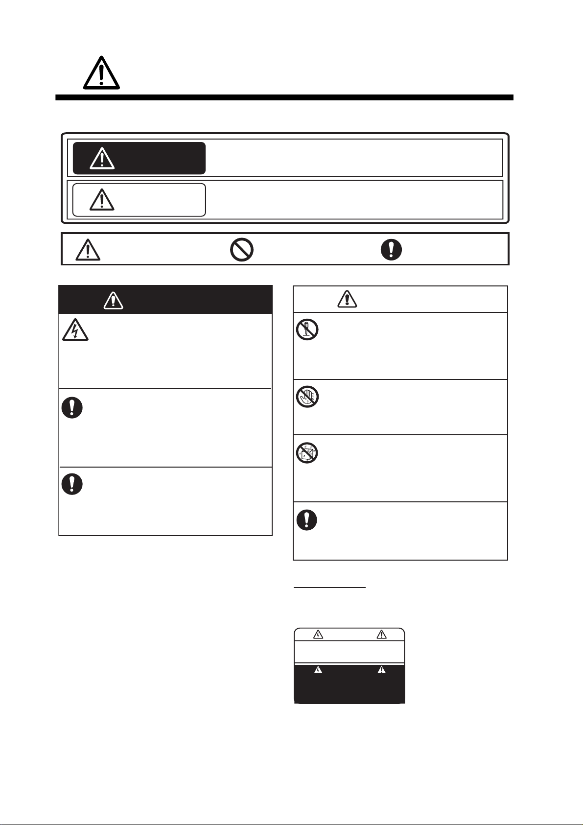
SAFETY INSTRUCTIONS
Read these safety instructions before you operate the equipment.
Indicates a condition that can cause death or serious injury if
WARNING
CAUTION
Warning, Caution
not avoided.
Indicates a condition that can cause minor or moderate injury if
not avoided.
Prohibitive Action
Mandatory Action
WARNING
Do not open the equipment.
This equipment uses high voltage that can
cause electrical shock.
Only qualified persons can work inside
the equipment.
Turn off power at switchboard if the
something is dropped inside the
equipment.
Fire or electrical shock can result if the
power remains on.
Turn off power at switchboard if the
equipment is emitting smoke or fire.
Fire or electrical shock can result if the
power remains on.
CAUTION
Do not disassemble or modify the
equipment.
Fire, electrical shock or bodily injury
can result.
Do not operate the equipment with
wet hands.
Fire or electrical shock can result.
Keep the equipment away from rain,
water and water splash.
Fire or electrical shock can result if water
gets into the equipment.
Use the correct fuse.
Use of a wrong fuse can cause bodily
injury or fire.
Warning Label
A warning label is attached to the equipment.
Do not remove the label. If the label is missing
or damaged, see your dealer about replacement.
WARNING
To avoid electrical shock, do not
remove cover. No user-serviceable
parts inside.
Name: Warning Label (1)
Type: 86-003-1011-3
Code No.: 100-236-233-10
ii
Page 5

TABLE OF CONTENTS
FOREWORD....................................................................................................................v
SYSTEM CONFIGURATION..........................................................................................vi
1. HOW THE BRIDGE ALARM SYSTEM OPERATES.............................................1-1
1.1 Bridge Alarm ..............................................................................................................1-1
1.2 Watch Safety Alarm....................................................................................................1-2
2. BRIDGE PANEL ....................................................................................................2-1
2.1 Controls......................................................................................................................2-1
2.2 How to Turn the Bridge Panel On/Off.........................................................................2-2
2.3 How to Adjust the Brilliance........................................................................................2-3
2.4 Standby Display..........................................................................................................2-4
2.5 Alarm Sequence.........................................................................................................2-6
2.5.1 Bridge alarm...................................................................................................2-6
2.5.2 Watch safety alarm.........................................................................................2-7
2.6 Help Area....................................................................................................................2-9
2.6.1 System failure indications...............................................................................2-9
2.6.2 Operational event indications.......................................................................2-11
2.6.3 Operation help indications............................................................................2-12
3. TIMER RESET PANEL, CABIN PANEL ...............................................................3-1
3.1 Timer Reset Panel......................................................................................................3-1
3.2 Cabin Panel................................................................................................................3-3
3.2.1 DUTY lamp.....................................................................................................3-3
3.2.2 ALARM lamp..................................................................................................3-3
4. ADMINISTRATOR MENU (Initial Settings)..........................................................4-1
4.1 How to Use the Administrator Menu...........................................................................4-1
4.2 Mode Select (Operation Mode) ..................................................................................4-3
4.2.1 Harbour mode ................................................................................................4-4
4.2.2 Bridge attended mode....................................................................................4-5
4.2.3 One-man mode ..............................................................................................4-6
4.3 Back-up Officer...........................................................................................................4-7
4.4 Captain Back-up.........................................................................................................4-7
4.5 Watch Time Interval....................................................................................................4-8
4.6 All Back-up Officer Call Interval..................................................................................4-8
4.7 Use Key Beep.............................................................................................................4-8
5. CALL FUNCTIONS................................................................................................5-1
5.1 Back-up Officer Call....................................................................................................5-1
5.2 Navigation Officer Call................................................................................................5-2
6. MAINTENANCE, TROUBLESHOOTING ..............................................................6-1
6.1 Maintenance...............................................................................................................6-1
6.2 Fuse Replacement .....................................................................................................6-2
6.3 Troubleshooting..........................................................................................................6-3
6.4 How to Check Connection Between Bridge Panel and Cabin Panels........................6-4
iii
Page 6

TABLE OF CONTENTS
APPENDIX 1 MENU TREE .......................................................................................AP-1
SPECIFICATIONS .....................................................................................................SP-1
INDEX..........................................................................................................................IN-1
iv
Page 7

FOREWORD
A Word to the Owner of the BR-1000
Congratulations on your choice of the BR-1000 Bridge Alarm System. We are confident you will
see why the FURUNO name has become synonymous with quality and reliability.
For over 60 years FURUNO Electric Company has enjoyed an enviable reputation for innovative
and dependable marine electronics equipment. This dedication to excellence is furthered by our
extensive global network of agents and dealers.
Your equipment is designed and constructed to meet the rigorous demands of the marine environment. However, no machine can perform its intended function unless properly operated and
maintained. Please carefully read and follow the operation and maintenance procedures set forth
in this manual.
Thank you for considering and purchasing FURUNO.
We would appreciate feedback from you, the end-user, about whether we are achieving our pur-
poses.
Features
The BR-1000 Bridge Alarm System collectively controls the warning notice from equipment on the
bridge and monitors watch officer’s presence to prevent marine accidents.
• Complies with IMO Resolution MSC.125(75) for Bridge Navigational Watch Alarm System
• Collectively manages and presents alarm information on the Bridge Panel
• Alarm information is sorted and displayed according to set priority
• Watch safety alarm watches for unattended bridge or operator disability
• Transmits alarm to backup officer if the Officer of the Watch fails to respond to active alarm or
emergency call
Software history
BR-1010 Application Program BR-1010 FPGA Program BR-1020 Program
2450041-01.xx
Initial version 06/2009
xx=minor change
0650117-01.xx
Initial version 06/2009
2450040-01.xx
Initial version 06/2009
v
Page 8
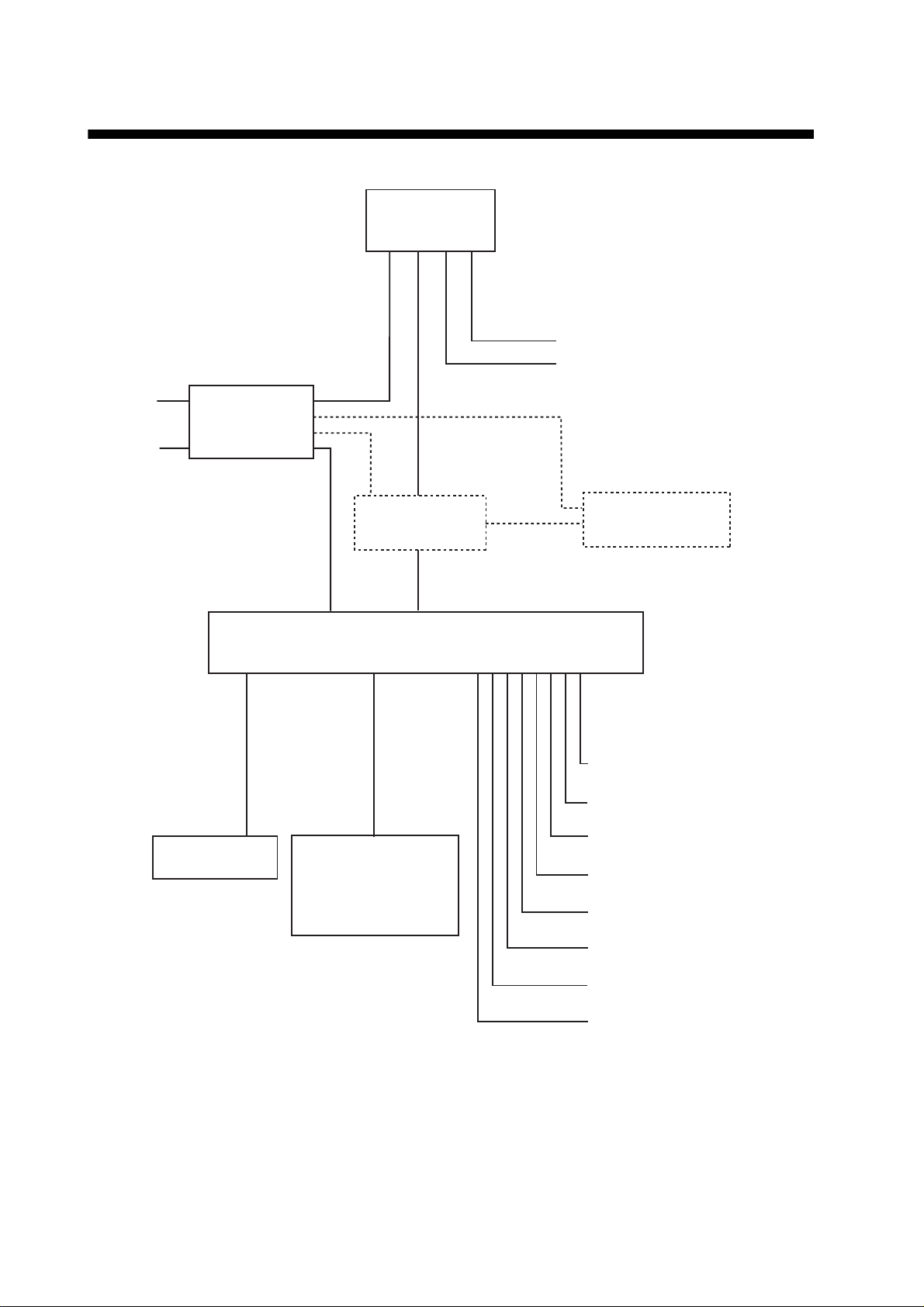
SYSTEM CONFIGURATION
BRIDGE PANEL
BR-1010
VDR
GPS
100-115/
200-230 VAC
24 VDC
CABIN PANEL
AC-DC
POWER SUPPLY
UNIT
PR-240
BR-1030
4 - 14 units
ETHERNET HUB
HUB-101
PROCESSOR UNIT
BR-1020
TIMER RESET PANEL
BR-1040
WATERTIGHT TIMER
RESET PANEL
BR-1060
PROCESSOR UNIT
BR-1020
Autopilot (2 lines)
IAS (2 lines)
External Siren
REMOTE ACK OUT (12 lines)
LOCAL ACK IN
(12 lines)
1 - 4 units
- Dashed lines indicate optional equipment.
- Environment category: All units protected from weather.
vi
OPERATOR FITNESS IN (7 lines)
ALARM IN (48 lines)
SYSTEM FAIL OUT (2 lines)
Page 9

1. HOW THE BRIDGE ALARM
SYSTEM OPERATES
The FURUNO BR-1000 Bridge Alarm System has the following purposes:
• Bridge Alarm: Control all warning notices from the navigation equipment installed
on the bridge.
• Watch Safety Alarm: Monitor bridge activity to detect operator disability which can
cause marine accidents.
1.1 Bridge Alarm
The bridge alarm controls all the warning notices from the navigation equipment installed on the bridge. When an equipment gives an alarm, the alarm is sent in three
stages.
• 1st stage: When a device connected to this system sends an alarm, the system
gives 30-second long visual (flashing lamp) and audible (buzzer) alarms from the
Bridge Panel and the Timer Reset Panel to tell the Officer of the Watch (hereafter
called OOW) on the bridge.
• 2nd stage: If the OOW does not acknowledge the 1st stage alarm, the Cabin Panel
in the living quarters of the selected back-up officer and the Cabin Panels fitted in
public areas give audible and visual alarms.
• 3rd stage: if no one acknowledges the 2nd stage alarm within the selected time in-
terval (90-180 s), all the Cabin Panels fitted in living quarters of all navigation officers and public areas give audible and visual alarms.
To stop the audible alarm, press the BUZ STOP key on the Bridge Panel. The audible
alarm stops at the Bridge Panel, Timer Reset Panel and the equipment that gave the
alarm.
After you stop the audible alarm, press the ACK key to acknowledge the alarm. The
Bridge Panel displays the visual alarm “Pending” and the visual alarm at the Timer Reset Panel is stopped. The “Pending” indication remains on the Bridge Panel until the
cause for the alarm is removed. Stop the audible alarm BEFORE
the alarm. If the buzzer is not stopped first, the visual alarm is not stopped when you
press the ACK key.
you acknowledge
1-1
Page 10
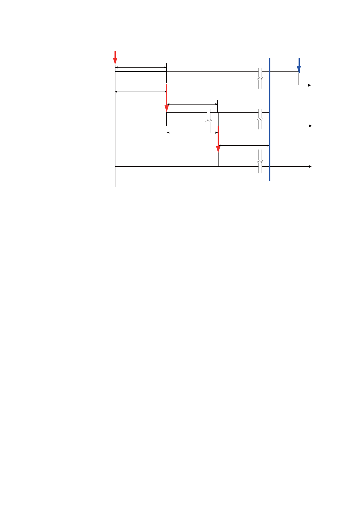
1. HOW THE BRIDGE ALARM SYSTEM OPERATES
External equipment
generates an alarm
BRIDGE PANEL
TIMER RESET PANEL
(incl. watertight type)
Back-up navigation officer quarters
and all public areas
CABIN PANEL
NO BUZZER STOP
Alarm forwarded
1st stage
Visual ALM*
+ Audible ALM
30 s
*Red flashing at Bridge Panel, Timer Reset Panel
Visual ALM (lighting)
+ Audible ALM
NO ACK
Visual ALM*
Visual ALM* + Audible ALM
NO BUZZER STOP
Alarm forwarded
2nd stage
BUZZER STOP
+ Audible ALM
NO ACK
Visual ALM (lighting)
+ Audible ALM
ACK
Reason
removed
Pending
CABIN PANEL in all
navigation officers quarters
(The CABIN PANELS in all public areas
continue the alarm.)
Bridge alarm sequence
1.2 Watch Safety Alarm
The main purpose of the watch safety alarm is to monitor bridge activity on the ship
that uses a “one-man bridge”. The system looks for the operation of equipment within
the selected time interval (3-12 minutes). The OOW validates operator fitness on the
bridge with the WATCH/RESET button on the Timer Reset Panel or any operation on
the Bridge Panel. The system also acknowledges the presence of the OOW if some
equipment connected to the BR-1000 (radar, ECDIS, etc.) is operated. The watch
safety alarm has four stages, one a prewarning stage.
• Prewarning: If the OOW does not validate operator fitness within the selected time
interval, a lamp on the Bridge Panel flashes (in red) and a lamp on the Timer Reset
Panel flashes (in yellow) for 15 seconds.
Variable (90-180 s)
3rd stage
Visual ALM (lighting)
+ Audible ALM
1-2
• 1st stage: If the OOW does not validate operator fitness in the prewarning stage,
the lamps flash an additional 15 seconds and a 15-second audible alarm sounds.
• 2nd stage: If the OOW does not validate operator fitness at the 1st stage, the alarm
is sent to the Cabin Panel in the living quarters of the selected back-up officer and
all the Cabin Panels fitted in public areas. These Cabin Panels give visual (illuminated lamp) and audible (buzzer) alarms.
• 3rd stage: If the OOW does not validate operator fitness within the selected time
interval (90-180 s), the Cabin Panel in the living quarters of all navigation officers
and all the Cabin Panels fitted in public areas give audible and visual alarms (illuminated lamp).
Page 11
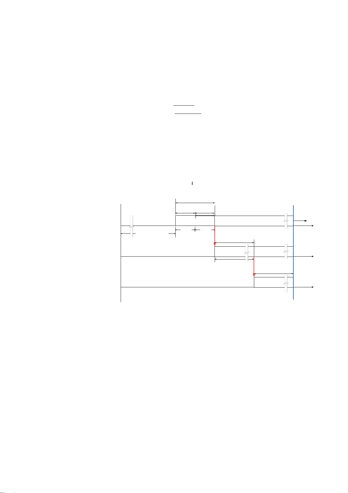
1. HOW THE BRIDGE ALARM SYSTEM OPERATES
The OOW stops the audible alarm and acknowledges the alarm. Then, audible and
visual alarms at the Bridge Panel, Cabin Panels and Timer Reset Panel are removed
and the watch safety timer is reset.
The interpretation of the prewarning 15-second visual alarm (flashing) and the15-second visual (flashing) and audible (buzzer) alarms at the 1st stage depends on the
mode type selected. The BR-1000 can be configured for IMO (International Maritime
Organization) or DNV (Det Norkse Veritas, Norwegian classification society).
IMO: Alarm given for 30 seconds AFTER
DNV: Alarm given for 30 seconds BEFORE
The required mode can be selected from the Service menu.
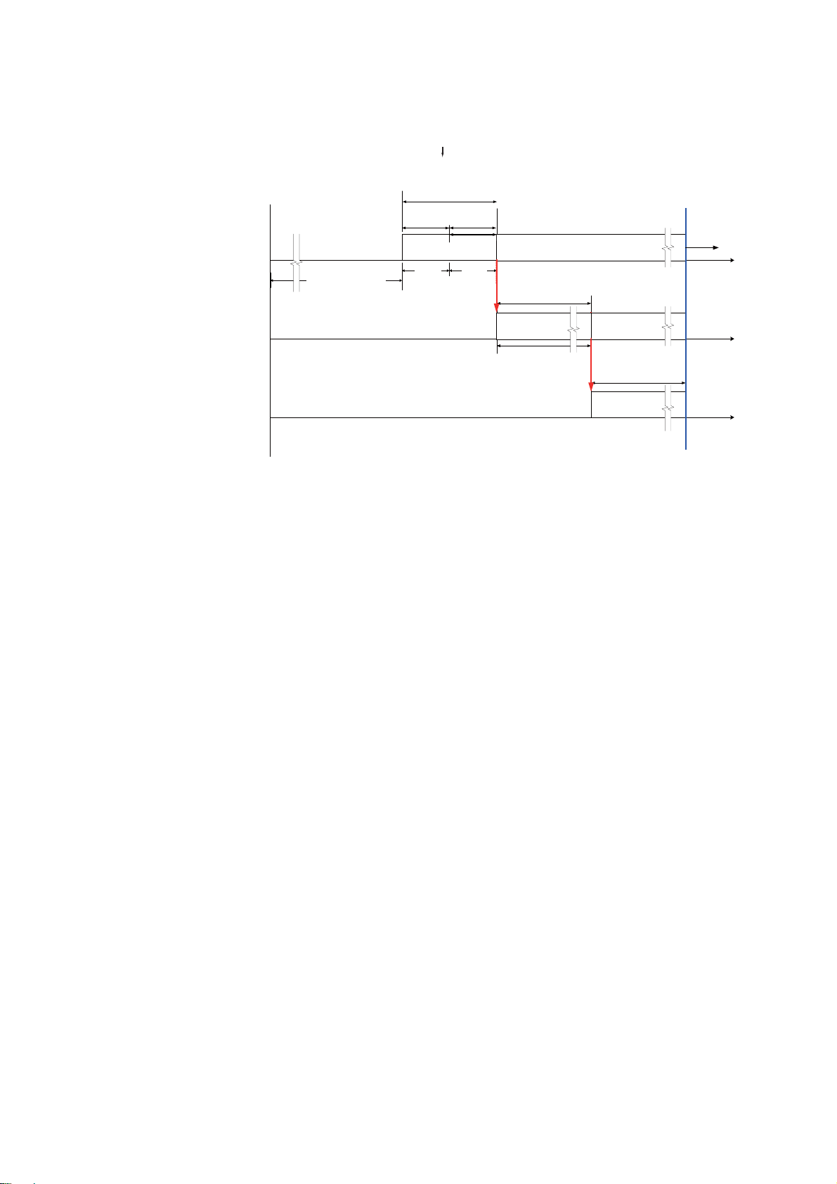
The sequence of the watch safety alarm in each mode is shown in the figures that fol-
low.
Timer starts
BRIDGE PANEL
TIMER RESET PANEL
(incl. watertight type)
Back-up navigation officer quarters
and all public areas
CABIN PANEL
CABIN PANEL in all
navigation officers quarters
(The CABIN PANELS in all public areas
continue the alarm.)
Specified interval
Variable (3-12 min)
selected time interval elapses.
selected time interval elapses.
- TIMER RESET
- OPERATOR FITNESS
- ACKNOWLEDGE
If none of the above is done
Alarm forwarded
30 s after specified
interval elapses
Prewarning
Visual ALM*
15 s
1st
stage
Visual ALM*
+ Audible
ALM
15 s
*Red flashing at Bridge Panel,
yellow flashing at Timer Reset Panel
Visual ALM*
NO BUZZER STOP
2nd stage
Visual ALM (lighting)
+ Audible ALM
Variable (90-180 s)
+ Audible ALM
Alarm forwarded
BUZZER STOP ACK
NO ACK
Visual ALM (lighting)
+ Audible ALM
3rd stage
Visual ALM (lighting)
+ Audible ALM
Timer
starts
Watch safety alarm sequence (IMO)
1-3
Page 12
1. HOW THE BRIDGE ALARM SYSTEM OPERATES
Timer starts
BRIDGE PANEL
TIMER RESET PANEL
(incl. watertight type)
Specified interval
Variable (3-12 min)
Back-up navigation officer quarters
and all public areas
CABIN PANEL
CABIN PANEL in all
navigation officers quarters
(The CABIN PANELS in all public areas
continue the alarm.)
Prewarning
Visual ALM*
- TIMER RESET
- OPERATOR FITNESS
- ACKNOWLEDGE
If none of the above is done
Alarm forwarded
30 s after specified
interval elapses
1st
*Red flashing at Bridge Panel,
stage
yellow flashing at Timer Reset Panel
Visual ALM*
+ Audible
ALM
15 s
15 s
Visual ALM (lighting)
+ Audible ALM
Variable (90-180 s)
Visual ALM*
+ Audible ALM
NO BUZZER STOP
Alarm forwarded
2nd stage
Visual ALM (lighting)
+ Audible ALM
Visual ALM (lighting)
+ Audible ALM
BUZZER STOP ACK
Timer
starts
NO ACK
3rd stage
Watch safety alarm sequence (DNV)
1-4
Page 13

2. BRIDGE PANEL
The Bridge Panel is the heart of the bridge alarm system. All settings are done from
the Bridge Panel.
2.1 Controls
㽳
㽴
㽸
㽵
㽹
㽶
㽺
㽷
㽻
㽲
No.
1 BRILL Turn the power ON and OFF. Adjust the brilliance.
2 Cursor pad,
3 ESC Return to previous setting or previous screen.
4 MENU Open the menu.
5 EDIT Go to the Alarm List when the bridge alarm display is shown.
6 BUZ STOP Stop the buzzer on all units connected to this system.
7 LIST Show the bridge alarm screen.
8 CALL BK-UP Call the Captain or other navigation officer when there is an emer-
9 TEST Test the buzzer.
10 ACK Bridge alarm: OOW acknowledges a bridge alarm (bridge alarm is
Control
Name
ENTER key
Description
Pad: Select item from the Alarm List, menu, etc.
Key: Validate a setting.
gency.
then set for “Pending”).
Watch safety alarm: OOW acknowledges presence on the bridge.
2-1
Page 14

2. BRIDGE PANEL
BRIDGE ALARM SYSTEM
BR-1000
FURUNO䇭ELECTRIC CO., LTD.
BRIDGE PANEL BR-1010
PROGRAM No. 2450041-01.xx
ROM: OK
RAM: OK
2.2 How to Turn the Bridge Panel On/Off
Press the BRILL key to turn on the Bridge Panel. The start-up screen appears.
The program number is shown and the system checks the ROM and RAM. If the ROM
and RAM are normal, OK appears for their check results. If NG (NoGood) appears for
any check result, reset the power to try to restore normal operation. If NG still appears,
contact your dealer.
Press any key at the start-up screen to go to the standby display (see section 2.4).
You can also go to the standby display if you wait 10 seconds after the completion of
the start-up check.
To turn off the Bridge Panel, press the BRILL key until the power goes off (approx. 10
seconds).
2-2
Page 15
2.3 How to Adjust the Brilliance
WATCH
ALARM
MODE
ONEMAN
BACK-UP
C/OFFICER
BRIDGE
ALARM
BRIDGE ALARM SYSTEM BR-1000
NO ALARM
TIME INTERVAL
3 MIN
Brilliance
43
1
50
DayNight
The system starts with the last-used brilliance setting. Adjust the brilliance as shown
in the procedure below. This procedure adjusts the brilliance in the “no-alarm state”.
1. Press the BRILL key to show the brilliance adjustment window.
2. BRIDGE PANEL
2. Press the right arrow on the Cursor pad to increase the brilliance. The maximum
brilliance is “50”.
3. Press the left arrow on the Cursor pad to decrease the brilliance. The minimum
brilliance is “1”.
4. Press the ESC key to close the window.
Alarm and brilliance level
The system increases the brilliance when the bridge alarm or watch alarm is given.
For the bridge alarm, the brilliance is increased by 10, up to a maximum of 50. The
brilliance is kept until the cause for the alarm is removed.
For the watch safety alarm, the brilliance is increased by 10, up to a maximum of 50.
If the alarm is acknowledged at the 1st stage, the previous brilliance is restored. If an
alarm is not acknowledged at the 1st stage (the alarm is then sent to the Cabin Panels), the previous brilliance is restored after the BUZ STOP and ACK keys are
pressed, in that order.
2-3
Page 16

2. BRIDGE PANEL
WATCH
ALARM
MODE
ONEMAN
BACK-UP
C/OFFICER
BRIDGE
ALARM
BRIDGE ALARM SYSTEM BR-1000
NO ALARM
TIME INTERVAL
3 MIN
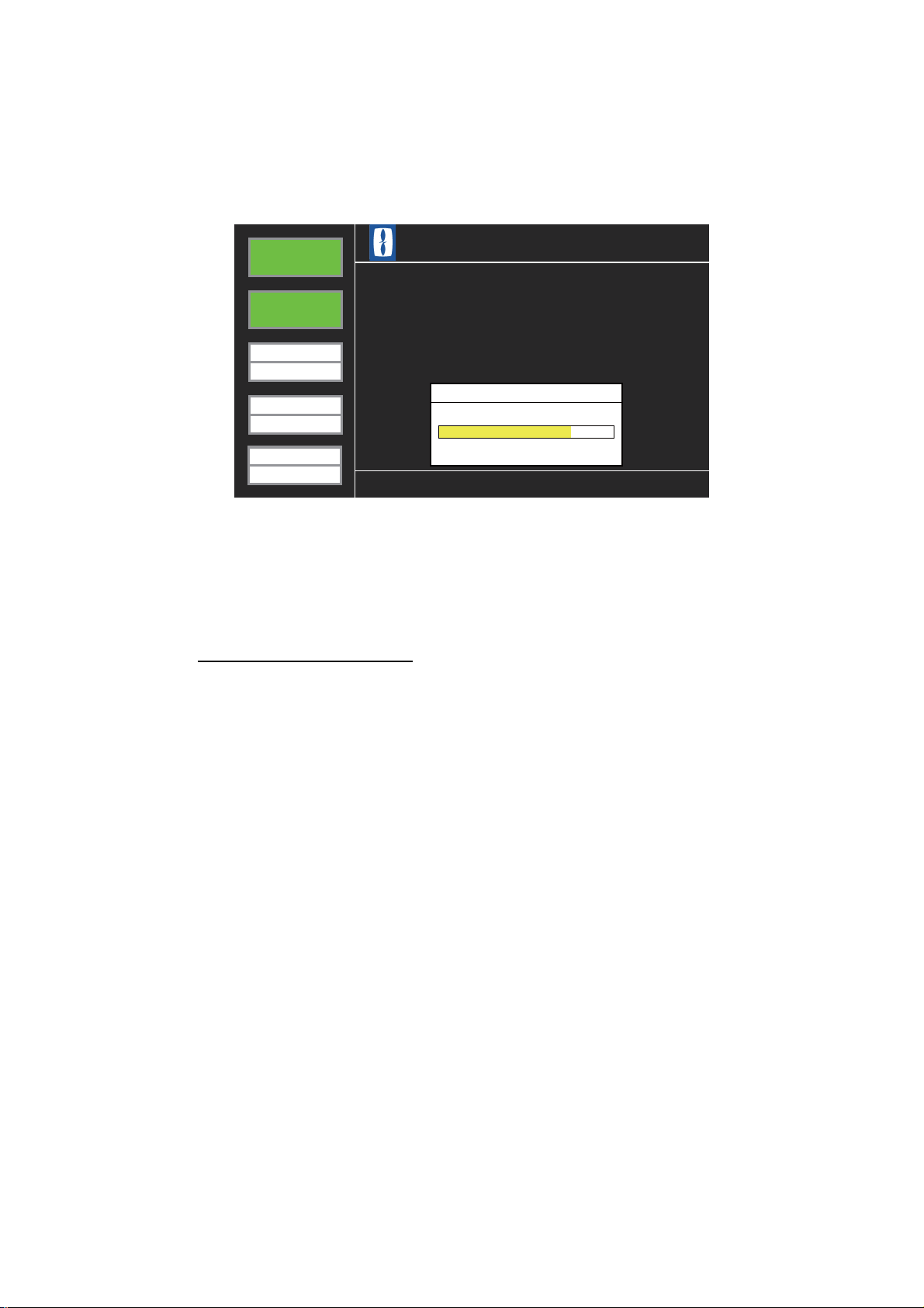
2.4 Standby Display
The standby display appears after the start-up is completed. This display is divided
into three areas, information area, status area, and help area.
Information
area
Help area
Status area
Standby display
Information area
All types of operating information appear here.
Status area
The status area has five boxes which show system status.
BRIDGE ALARM box
- Green: Standby (no bridge alarms)
- Red/Gray flashing: Bridge alarm active
- Yellow: Pending alarm is active
- Gray: Bridge alarm OFF
WATCH ALARM box
- Green: Standby condition (no watch safety alarms)
- Red/Gray flashing: Watch safety alarm active
- Gray: Watch safety alarm OFF
2-4
MODE box
- HARBOUR: Harbour mode (When this mode is selected, the buzzer sounds and
MODE is colored red. MODE becomes yellow after BUZ STOP and ACK keys are
operated.)
- ATTENDED: Bridge attended mode
- ONE MAN: One-man mode
BACK-UP box
The BACK-UP box shows the name of the back-up officer, for example, C-Officer.
Page 17

2. BRIDGE PANEL
TIME INTERVAL box
The TIME INTERVAL box shows the time interval setting for the 1st stage alarm for
the watch safety alarm. The progress bar (yellow) at the bottom half of the box moves
right as the end of the interval nears.
Help area
Help for controls, etc. See section 2.6.
2-5
Page 18

2. BRIDGE PANEL
WATCH
ALARM
MODE
ONEMAN
BACK-UP
C/OFFICER
TIME INTERVAL
3 MIN
BRIDGE
ALARM
Description
Priority
Tag
Auto Alarm Pop-up Display
004
028
No.1 Radar CPA/TCPA/GZ
Urgency
No.1 GPS Off-Track
Primary
BRIDGE
ALARM
2.5 Alarm Sequence
2.5.1 Bridge alarm
1. When a device connected to the system gives an alarm, the Bridge Panel gives
the audible alarm and flashes the BRIDGE ALARM box in red. The information
area shows the name of the alarm.
Flashing in
red
Alarm name
Bridge alarms given
2. Press the BUZ STOP key on the Bridge Panel to stop the buzzer and the ACK
key to acknowledge the alarm. Confirm the alarm also at the device that gave the
alarm. The Bridge Panel shows the Alarm List, an example of which is shown below.
The buzzer stops only at the equipment which has the Remote ACK Out signal
connected to this equipment.
The Alarm List shows in yellow the alarms for which their cause have not yet been
removed.
BRIDGE
ALARM
WATCH
ALARM
MODE
ONEMAN
BACK-UP
C/OFFICER
TIME INTERVAL
3 MIN
1 2 3 4 5 6 7 8 9
Tag
001
002
003
004
005
006
007
008
No.1 Radar Sys Fail
No.2 Radar Sys Fail
No.3 Radar Sys Fail
No.1 Radar CPA/TCPA/GZ
No.2 Radar CPA/TCPA/GZ
No.3 Radar CPA/TCPA/GZ
No.1 RADAR System Error
No.2 RADAR System Error
Description
10 11 12
Priority
Secondary
Secondary
Secondary
Urgency
Urgency
Urgency
Secondary
Secondary
2-6
Note: In the one-man mode, if the BUZ STOP and ACK keys are not operated
within 30 seconds after an alarm is given, the alarm is sent to the quarters of the
back-up officer and all public areas. If the alarm is still not acknowledged within
the selected time interval, the alarm is sent to the quarters of all the navigation officers.
Page 19

2. BRIDGE PANEL
3. Press the ESC key, and the Bridge Panel shows PENDING ALARM.
Pending alarm indicates that an alarm has been acknowledged, but the cause for
the alarm has not been removed. The PENDING ALARM indication is erased after
the cause for the alarm is removed.
BRIDGE
ALARM
WATCH
ALARM
MODE
ONEMAN
BRIDGE ALARM SYSTEM BR-1000
CAUTION!
PENDING ALARM
BACK-UP
C/OFFICER
TIME INTERVAL
3 MIN
Note: If the Bridge Panel receives a buzzer stop signal from the device that gave
an alarm, the buzzer at the Bridge Panel is stopped, but the BRIDGE ALARM box
continues to flash (in red). Press the ACK key to acknowledge the alarm. If the
key is not operated in the one-man mode, the alarm is sent to the Cabin Panels
after the time interval has elapsed.
2.5.2 Watch safety alarm
“Pending” display
The watch safety alarm checks for the presence of the OOW on the bridge in the oneman bridge operation. If a radar, ECDIS or Bridge Panel is operated within the selected time interval, no alarm is given. If no equipment is operated, the Bridge Panel gives
an alarm to tell the OOW. If that alarm is not acknowledged at the bridge, the alarm is
then sent to the Cabin Panel in the quarters of the back-up officer and all the Cabin
Panels fitted in public areas. If those alarms are not acknowledged, the alarm is sent
to the quarters of all navigation officers.
The watch safety alarm is given in the following conditions.
1) One-man mode
The watch safety alarm activates when the track control system or heading control
system goes on for the attended mode. The watch safety alarm is inoperative in
the Harbour mode.
2) Operator fitness signal is not input by the OOW
The operator fitness signal is input when a device on the bridge is operated. The
following equipment give this signal when operated.
Radar Operate any key or control.
ECDIS Operate any key or control other than the trackball.
Bridge Panel Operate any key.
Other A device that has the operator fitness signal connected is
operated.
2-7
Page 20

2. BRIDGE PANEL
WATCH
ALARM
MODE
ONEMAN
BACK-UP
C/OFFICER
BRIDGE
ALARM
BRIDGE ALARM SYSTEM BR-1000
NO ALARM
TIME INTERVAL
3 MIN
3) If the RESET/WATCH key on the Timer Reset Panel is not operated.
Note: The watch alarm timer continues to operate during an active bridge alarm.
The sequence of the watch safety alarm is as follows:
1. After turning on the Bridge Panel and the standby display appears, the timer for
the watch safety alarm starts.
The yellow bar in the setting indication in the TIME INTERVAL box (lower left corner) moves right as the end of the selected time interval nears.
The time interval is set on the Administrator Menu. See Chapter 4.
When the end of the time interval has come, the yellow bar completely fills the bottom half of the TIME INTERVAL box. The timing for the beginning of the alarm is
different between the IMO and DNV modes. The time interval indication is filled as
follows:
• DNV mode: The progress bar fills the time interval indication area 30 seconds
BEFORE
• IMO mode: The progress bar fills the time interval indication area AFTER
the time interval has come.
the
time interval has come.
2. When the operator fitness signal is input before the progress bar completely fills,
the timer is reset and the bar is erased.
3. The progress bar fills the interval indication and the Bridge Panel releases a 15second visual alarm. The WATCH ALARM box flashes in red and the message
PREWARNING WATCH ALARM appears in the information area.
BRIDGE ALARM SYSTEM BR-1000
BRIDGE
BRIDGE
ALARM
ALARM
WATCH
WATCH
ALARM
ALARM
BRIDGE ALARM SYSTEM BR-1000
2-8
PREWARNING
MODE
MODE
ONEMAN
ONEMAN
BACK-UP
BACK-UP
C-OFFICER
C/OFFICER
TIME INT
TIME INTERVAL
3 MIN
3 MIN
PREWARNING
WATCH ALARM
WATCH ALARM
Page 21

2. BRIDGE PANEL
4. If there is no operator fitness signal input within the 15-second visual alarm, the
Bridge Panel releases a 15-second audible alarm (buzzer). The WATCH ALARM
box continues to flash in red and the message WARNING! WATCH ALARM appears in the information area.
BRIDGE ALARM SYSTEM BR-1000
BRIDGE
BRIDGE
ALARM
ALARM
WATCH
WATCH
ALARM
ALARM
MODE
MODE
ONEMAN
ONEMAN
BACK-UP
BACK-UP
C-OFFICER
C/OFFICER
TIME INT
TIME INTERVAL
3 MIN
3 MIN
BRIDGE ALARM SYSTEM BR-1000
WARNING!
WARNING!
WATCH ALARM
WATCH ALARM
5. If there is no operator fitness signal input within 15 seconds, the Cabin Panel in
the quarters of the back-up officer and all the Cabin Panels in public areas give
audible and visual alarms.
Note: The alarm cannot be stopped from a Cabin Panel.
6. At the Bridge Panel, stop the buzzer with the BUZ STOP key and acknowledge
the alarm with ACK key. NO ALARM appears in the information area on the
Bridge Panel.
Note: Make sure to operate the ACK key. The audible and visual alarms are sent
to the quarters of all navigation officers and all public areas if only the BUZ STOP
key is operated.
7. If the operations at step 6 are not done within the selected time interval, the audible and visual alarms are then sent to the Cabin Panel in the quarters of all navigation officers. This interval is set on the Administrator Menu. See Chapter 4.
8. Stop the buzzer and acknowledge the alarm with the BUZ STOP and ACK keys
on the Bridge Panel.
2.6 Help Area
The help area displays system failures, operational events, operation help, etc. If multiple system failures or operational events occur together, they appear in order of priority. The order from high to low is 1: System failure, 2: Operational events, 3:
Operation help, 4: Pending matters. “Pending” appears for system failure and operational events, and it means that the reason for an alarm has not been removed.
2.6.1 System failure indications
This section describes how system failures are given and the accompanying operation
flow.
1) The help area shows system failure messages in red:
[FAIL] YYY: xxxxx (YYY is failure ID, and xxxxx is the description of the system
failure). If multiple system failures are found, they are displayed alternately.
2-9
Page 22

2. BRIDGE PANEL
2) The buzzer at the Bridge Panel sounds.
There is no visual or audible alarm at the Timer Reset Panel nor is the alarm forwarded to the Cabin Panel.
3) Press the BUZ STOP key to stop the buzzer.
4) Press the ACK key to acknowledge the alarm.
5) The color of the message changes to yellow.
6) The message is erased when the reason for the alarm is removed.
The table below shows the system failure messages.
MSG IDID
No.
FAIL 001 Bridge Panel Operating
Fail
FAIL 002 No.1 Processor Unit
Communication Fail
FAIL 003 No.2 Processor Unit
Communication Fail
FAIL 004 No.1 Processor Unit
Operating Fail
FAIL 005 No.2 Processor Unit
Operating Fail
FAIL 006 Modbus Time out Cannot connect with Modbus.
FAIL 007 Modbus Format Error Modbus format error:
FAIL 008 PR-240 AC Power Fail No AC input at PR-240. The system oper-
Indication
Error at Bridge Panel
No connection with No.1 Processor Unit
No connection with No.2 Processor Unit
Problem with command at the No. 1 Processor Unit.
Problem with command at the No. 2 Processor Unit.
- Illegal Function
- Illegal Data Address
- Illegal Data Value
ates with DC power.
Problem
2-10
FAIL 009 Please check the definition
File.
Error found in definition file at equipment
startup. Below are the definition file errors.
• Duplicate part found in Modbus address IO in the definition file.
• An address out of address range is
found during check of Modbus address
setting range and IO address.
• Duplicate Cabin Panel names found.
• “Type” is set to “Captain” on two or
more Cabin Panels.
Page 23

2.6.2 Operational event indications
When an operational event occurs, the Bridge Panel shows the related message in
red in the help area, in the following format:
[OPER] YYY:xxxxxx (YYY is ID No., and xxxx is the message)
Multiple events are displayed alternately.
The table below describes the operational messages.
2. BRIDGE PANEL
MSG IDID
No.
OPER 001 Harbour Mode Select Operation mode changed from Attended
OPER 002 Watch Safety System is
OPER 003 Press [BUZ STOP] Key
OPER 004 Press [ACK] Key 1) Bridge alarm given and buzzer stopped
OPER 005 Press Any Key. Watch safety alarm given and this indication
OPER 006 Press [CALL BK-UP]
OPER 007 The alarm was trans-
OPER 008 The alarm was trans-
OPER 009 Press [TEST] key to
Indication Event
Mode or One-Man Mode to Harbour Mode.
Track Control System or Heading Control
activated
to stop buzzer.
key to stop alarm.
mitted. (2nd stage)
mitted. (3rd stage)
stop buzzer.
System activates.
1) Buzzer is sounding for bridge alarm in
1st, 2nd or 3rd stage. (Not displayed if
buzzer stopped with Local ACK.)
2) Buzzer is sounding for watch safety
alarm in 2nd or 3rd stage.
3) Buzzer is sounding for system failure.
4) Buzzer is sounding for operational event
in 1st, 2nd or 3rd stage.
(with BUZ STOP key) at 1st, 2nd or 3rd
stage, or buzzer stopped by Local ACK
but alarm not acknowledged.
2) Watch safety alarm given and buzzer
stopped (with BUZ STOP key) at 2nd or
3rd stage, or buzzer stopped but alarm
not acknowledged.
3) System failure given and buzzer stopped
(with BUZ STOP key) but alarm not acknowledged.
4) Operational event given and buzzer
stopped (with BUZ STOP key) at 1st, 2nd
or 3rd stage but alarm not acknowledged.
appears during Prewarning 1 and Prewarning 2 (1st stage) periods. Not displayed if a
bridge alarm is currently active.
*Not displayed when 001 or 002 occur.
Press CALL BK-UP key to stop buzzer at all
Cabin Panels.
1) The Bridge Panel changed the alarm
stage from 1st to 2nd.
2) The watch safety alarm stage changed
from 1st to 2nd.
1) The Bridge Panel changed the alarm
stage from 2nd to 3rd.
2) The watch safety alarm stage changed
from 2nd to 3rd.
Press TEST key on Bridge Panel to stop
buzzer test.
2-11
Page 24

2. BRIDGE PANEL
For ID 001-003, the buzzer at the Bridge Panel sounds and the Timer Reset Panel
flashes its BRIDGE ALARM button and sounds the buzzer. If the BUZ STOP and
ACK keys are not operated within 30 seconds after an event has occurred, the alarm
is then sent to the Cabin Panels.
For ID 004-008, only the lamp flashes (in red). The buzzer is not given and the alarm
is not sent to the next stage.
2.6.3 Operation help indications
Operation help is shown in white characters.
[GUID] YYY: xxxxxxx (YYY is ID no., xxxxxxx is the help message)
A help message is erased after you operate the equipment according to the help. Below are the help messages.
MSG IDID
No.
GUID 001 Press [ESC] key to exit. Use ESC key to exit from currently
GUID 002 Press [LEFT]/[RIGHT]
key to select page.
GUID 003 Press [UP]/[DOWN] key
to select an item.
GUID 004 Out of range You entered a numeric value that is out of
GUID 005 Duplicate name exists. You entered a name that already exists.
GUID 006 Press [ENTER] key to
edit
GUID 007 Press [UP]/[DOWN]/
[LEFT]/[RIGHT] key
Message Meaning
displayed menu.
1) Select page when Bridge Alarm Display
is shown.
2) Select page when simplified editing
display is shown.
3) Select alarm settings when simplified
editing display is shown.
Use up/down arrow on Cursor pad to select
item on menu.
specified input range.
Edit selected Cabin Panel from Cabin Panel
Setting menu.
1) Operate arrow pads on Cursor pad to
select a Cabin Panel from Cabin Panel
Setting Menu.
2) Select a Cabin Panel to call with Nav.
Off. Call function.
2-12
GUID 008 To select an item. Continuation of GUID007
GUID 009 Press [ENTER] key to
call.
Press the ENTER button to call Cabin Panel
selected with Nav. Off. Cal function.
Page 25

3. TIMER RESET PANEL, CABIN PANEL
3.1 Timer Reset Panel
The Timer Reset Panel is installed on the bridge, and the Watertight Timer Reset Panel is installed on the wing. A total of four can be installed.
TIMER RESET PANEL WATERTIGHT TIMER RESET PANEL
When the bridge alarm is given
When this system receives an alarm from an external equipment, both the Bridge Panel and the Timer Reset Panel(s) give audible and visual alarms. The BRIDGE ALARM
button on the Timer Reset Panel flashes (in red) and the audible alarm sounds.
The Timer Reset Panel cannot stop the buzzer or acknowledge an alarm.
When the watch safety alarm is given
If the WATCH/RESET button is pressed within the selected time interval, the watch
timer is reset. If operation is not confirmed within the selected time interval, the
WATCH/RESET button flashes (in yellow) and the buzzer sounds. This operation is
different between the IMO and DNV modes.
• IMO mode
1) The WATCH/RESET button flashes (in yellow) every second for 15 seconds after the selected time interval ends.
2) The WATCH/RESET button flashes (in yellow) an additional 15 seconds after
the selected time interval ends, accompanied by a 15-second audible alarm.
3-1
Page 26

3. TIMER RESET PANEL, CABIN PANEL
• DNV mode
1) The WATCH/RESET button flashes (in yellow) every second from 30 seconds
before the selected time interval ends and continues until 15 seconds before the
interval ends.
2) The WATCH/RESET button flashes (in yellow) every second for an additional
15 seconds before the selected time interval ends, accompanied by a 15-second audible alarm.
You can reset the watch alarm at the 1st stage (before the alarm is sent to the next
stage) with the WATCH/RESET button (yellow) on the Timer Reset Panel. If the alarm
is sent to the 2nd or 3rd stage, the alarm cannot be stopped from the Timer Reset Panel. To acknowledge the alarm from the 2nd or 3rd stage, use the BUZ STOP and ACK
keys on the Bridge Panel.
Note 1: Press the WATCH/RESET button with a touch-and-release action to reset the
watch timer. The watch timer is not reset if the button is pressed and held.
Note 2: You can test the lamps in the buttons and the buzzer individually if you press
the WATCH/RESET and BRIDGE ALARM buttons together.
3-2
Page 27

3.2 Cabin Panel
The Cabin Panel is installed in all navigation officers’ quarters and in public areas. The
Cabin Panel releases audible and visual alarms when a bridge alarm is given, or the
OOW did not confirm presence on the bridge within the selected time interval in the
watch safety alarm.
3. TIMER RESET PANEL, CABIN PANEL
3.2.1 DUTY lamp
One-man mode: The DUTY lamp on the Cabin Panel in the quarters of the back-up
navigation officer and public areas is illuminated (in yellow). The illuminated yellow
lamp indicates that a Cabin Panel is in the 2nd stage of an alarm sequence.
Harbour or attended mode: The DUTY lamp is not illuminated because no alarms
are sent to Cabin Panels in the harbour or attended mode. The lamp lights when the
track control system or heading control system goes on in the attended mode.
3.2.2 ALARM lamp
Bridge alarm
One-man mode: The ALARM lamp lights (in red) and the buzzer sounds in the 2nd
and 3rd stage of the bridge alarm sequence.
Harbour or attended mode: No visual or audible alarms are generated in these
modes.
CABIN PANEL
3-3
Page 28

3. TIMER RESET PANEL, CABIN PANEL
Watch safety alarm
One-man mode: The ALARM lamp lights (in red) and the buzzer sounds in response
to an alarm sent to the 2nd and 3rd stage.
Attended mode: The ALARM lamp lights (in red) and the buzzer sounds in the 2nd
and 3rd stage when the track control system or heading control system goes on.
Note: You can test the lamps in the buttons and the buzzer if you press the DUTY and
ALARM buttons together. The connection between the Cabin Panel, Bridge Panel are
also checked. See section 6.4.
3-4
Page 29

4. ADMINISTRATOR MENU
A
A
(Initial Settings)
The initial settings set the equipment according to the requirements of your ship. Only
the administrator of the system can enter the initial settings. All initial settings are entered from the Bridge Panel, on the Administrator menu.
The following occurs within the system during the input of initial settings.
• The system continues to monitor the bridge and watch safety alarms, but alarms are
not generated.
• If an alarm is active, you can open the menu after you acknowledge the alarm with
the BUZ STOP and ACK keys.
• After the menu is closed, the last-used operation modes for the bridge alarm and
watch safety alarm are restored. (If a device generates an alarm while the menu is
open, the bridge alarms start from the 1st stage after the menu is closed.)
If a device gives an alarm while the menu is open, the timer is reset when the menu is
closed. (Alarms are not forwarded when the menu is closed.)
4.1 How to Use the Administrator Menu
The menu is closed if you do not operate a control in 60 seconds.
1. Press the MENU key. The message “Enter Password” appears.
BRIDGE ALARM SYSTEM BR-1000
B
I
E
BRIDGE
ALARM
WATCH
ALARM
MODE
ONEMAN
BACK-UP
C/OFFICER
TIME INTERVAL
3 MIN
L
NO ALARM
Enter Password
M B
4-1
Page 30

4. ADMINISTRATOR MENU (Initial Settings)
WATCH
ALARM
MODE
ONEMAN
BACK-UP
C/OFFICER
TIME INTERVAL
3 MIN
BRIDGE
ALARM
Back-up Officer Select
Captain Back-up
Watch Time Interval Select (min)
All Back-up Officer Call Interval (sec)
Mode Select
3 min
OneMan
C/Officer
Description
Set
120 sec
Enable
Administrator Menu
Use Key Beep
Enable
WATCH
ALARM
MODE
ONEMAN
BACK-UP
C/OFFICER
TIME INTERVAL
3 MIN
BRIDGE
ALARM
Back-up Officer Select
Captain Back-up
Watch Time Interval Select
All Back-up Officer Call Interval
Mode Select
3 min
Harbour
C/Officer
Description
Set
120 sec
Enable
Adm inistra tor Me nu
Use Key Beep
Enable
2. Press the up, right, down and left arrows on the Cursor pad then press the ESC
and LIST keys to show the Administrator menu. The currently selected item is
highlighted in blue.
3. Use the up or down arrow to select an item then press the ENTER key.
An options selection window for the item selected appears.
Blue
highlight
Mode Selec t
-up
OneMan
3
4. Press the same arrow on the Cursor pad that is shown in the window to show
available options. If you press the left arrow, other options appear.
C/
Mode Selec t
-up
Attended
Mode Selec t
-up
Harbour
C/
3
C/
3
5. Press the ENTER key. The options window closes and the option selected for the
item appears in yellow on the menu.
Selected option
(yellow)
6. Do steps 3-5 to set other items.
4-2
Page 31

4. ADMINISTRATOR MENU (Initial Settings)
WATCH
ALARM
MODE
ONEMAN
BACK-UP
C/OFFICER
TIME INTERVAL
3 MIN
BRIDGE
ALARM
Back-up Officer Select
Captain Back-up
Watch Time Interval Select
All Back-up Officer Call Interval
Mode Select
3 min
OneMan
C/Officer
Description
Set
120 sec
Enable
Adm inistra tor Me nu
Do you w ant to s a ve ?
Yes
No Cancel
7. Press the ESC key to quit. You are asked “Do you want to save?”.
8. Use the arrow pads to select Yes then press the ENTER key.
Your settings are saved then the standby display appears. If you select No, the set-
tings are not saved and the Alarm List appears. Use Cancel to return to the Administrator menu.
Note: After the menu is closed, the bridge alarm and watch safety alarm are reset. In
the “Pending” condition the menu is open then closed and the bridge alarm starts from
the 1st stage. (This also occurs if there is no key operation at the password entry
screen for one minute.) if this occurs, use the BUZ STOP and ACK keys to stop the
alarm. If those keys are not operated, the alarm is forwarded to the Cabin Panel.
The next several sections describe the contents of the Administrator menu.
4.2 Mode Select (Operation Mode)
There are three operation modes. The operation of the bridge alarm and watch safety
alarm changes with the operating mode.
Operation
mode
HCS*1 or TCS*2:
OFF
SYS
FUNC*
3
Harbour OFF None OFF None OFF None OFF None
Bridge alarm Watch safety alarm
HCS or TCS: ON HCS or TCS: OFF HCS or TCS: ON
ALM
FWD*
4
SYS
FUNC
ALM
FWD
SYS
FUNC
ALM
FWD
FUNC
SYS
ALM
FWD
Bridge
OFF None ON Yes ON None ON None
Attended
One-Man ON Yes ON Yes ON Yes ON Yes
1
*
HCS=Heading Control System
2
TCS=Track Control System
*
3
SYS FUNC=System Function
*
4
ALM FWD=Alarm forward
*
4-3
Page 32

4. ADMINISTRATOR MENU (Initial Settings)
WATCH
ALARM
MODE
HARBOUR
BACK-UP
C/OFFICER
BRIDGE
ALARM
BRIDGE ALARM SYSTEM BR-1000
NO ALARM
TIME INTERVAL
3 MIN
WATCH
ALARM
MODE
HARBOUR
BACK-UP
C/OFFICER
BRIDGE
ALARM
BRIDGE ALARM SYSTEM BR-1000
NO ALARM
TIME INTERVAL
3 MIN
4.2.1 Harbour mode
Use this mode when you enter a harbor. The bridge alarm system is OFF in this mode.
The BRIDGE ALARM box is gray and the Bridge Panel continues to monitor the equipment. If a bridge alarm is generated, the pop-up display appears on the Bridge Panel,
but the Bridge Panel and Timer Reset Panel do not release the audible alarm. Alarms
are not sent to the Cabin Panels.
The display shown below appears when you change the operating mode to the harbour mode.
• The BRIDGE ALARM and WATCH ALARM boxes are gray. A gray box indicates
that the related function is OFF. HARBOUR in the MODE box is red.
Grayed out
(Function OFF)
Red
• The buzzer sounds. Press the BUZ STOP and ACK keys. HARBOUR then is col-
ored yellow.
Yellow
4-4
Page 33

4.2.2 Bridge attended mode
WATCH
ALARM
MODE
ATTENDED
BACK-UP
C/OFFICER
BRIDGE
ALARM
BRIDGE ALARM SYSTEM BR-1000
NO ALARM
TIME INTERVAL
3 MIN
Use this mode when you are underway and more than one navigator (including the
Captain) is on the bridge. The BRIDGE ALARM box on the Bridge Panel is green. The
WATCH ALARM box is gray and the MODE-ATTENDED box is white.
Green
Gray
4. ADMINISTRATOR MENU (Initial Settings)
4-5
Page 34

4. ADMINISTRATOR MENU (Initial Settings)
WATCH
ALARM
MODE
ONEMAN
BACK-UP
C/OFFICER
BRIDGE
ALARM
BRIDGE ALARM SYSTEM BR-1000
NO ALARM
TIME INTERVAL
3 MIN
4.2.3 One-man mode
Use this mode on the open sea when only one OOW is on the bridge; for example,
nighttime. The BRIDGE ALARM and WATCH ALARM boxes are green. Green means
respective function is active. The MODE-ONE MAN box is white.
Green
(Function ON)
Notes
• The harbour mode is different from the bridge attended mode. The watch safety
alarm is OFF always even when the track control system or heading control system
is turned ON.
• The watch safety system activates in the bridge attended mode when the Track
Control System or Heading Control System is turned ON. When one is turned on,
the Bridge Panel operates as follows.
1) When the track control system or heading control system is turned ON, the help
area indicates that the watch safety system is activated.
2) The operator presses the BUZ STOP and ACK keys to stop the buzzer and acknowledge the alarm.
3) The message in the help area disappears.
4) The WATCH ALARM box lights in green and the watch safety system activates.
5) The DUTY lamp lights on the Cabin Panel in the quarters of the back-up navigation officer. Even if the DUTY lamp lights the alarm is not forwarded.
• In the bridge attended mode, the following occurs when the track control system or
heading control system is turned off.
1) When track control system or heading control system is turned OFF, the system
operates with the selected operating mode.
2) The DUTY lamp goes off on the Cabin Panel in the quarters of the back-up nav-
igation officer and the Cabin Panels in public areas.
4-6
Page 35

4.3 Back-up Officer
Back-up Officer Select
C/Officer
Back-up Officer Select
1/Officer
Back-up Officer Select
2/Offic er
Back-up Officer Select
3/Officer
BACK-UP
C/OFFICER
BACK-UP
1/OFFICER
BACK-UP
2/OFFICER
BACK-UP
3/OFFICER
C a p t a i n B a c k-up
Disa ble Enable
When an alarm is generated and the OOW does not acknowledge the alarm, the alarm
is sent to the quarters of the back-up navigation officer after the selected time interval
has elapsed. This section shows you how to select a back-up navigation officer.
1. Open the Administrator menu, select [Back-up Officer Select] and press the
ENTER key.
The back-up officer selection window appears. The names shown in the window
were set at installation. To change the names, contact a FURUNO agent or dealer.
2. Use the left or right arrow on the Cursor pad to display a name. For example,
C/Officer, 1/Officer, 2/Officer, 3/Officer. If those names have been registered, the
window looks like the ones shown below.
4. ADMINISTRATOR MENU (Initial Settings)
3. Press the ENTER key to close the window. The name of the selected back-up officer appears in the Set column in the Administrator menu.
4. Press the ESC key to quit. The selected back-up officer appears in the BACK-UP
box at the bottom left corner of the screen.
4.4 Captain Back-up
Select whether to include the Captain as a back-up navigation officer. That is, select
whether to forward the alarm to the Cabin Panel in the Captain’s room in the 2nd stage
or the 3rd stage.
Select [Enable] or [Disable]. See the description below.
Selection Function
C a p t a i n B a c k-up
Enable The Captain is included in the 2nd stage. The DUTY lamp lights,
and in the 2nd stage the ALARM lamp lights and the buzzer
sounds.
Disable The Captain is not included in the 2nd stage. The DUTY lamp is
off. In the 3rd stage, the ALARM lamp lights and the buzzer
sounds.
4-7
Page 36

4. ADMINISTRATOR MENU (Initial Settings)
Watch Time Interval Select (min)
3 min
TIME INTERVAL
3 MIN
All B a c k-up Officer Call Interval (sec)
90 sec 120 sec 150 sec
180 sec
Use K ey B eep
Disa ble
Use K ey B eep
Enable
4.5 Watch Time Interval
Set the operation confirmation time for the watch safety alarm. The range is 3-12
(min). If the OOW does not confirm presence within this time period, the alarm is forwarded.
The selected interval appears in the TIME INTERVAL box.
4.6 All Back-up Officer Call Interval
Set the time interval of the 2nd stage. If the BUZ STOP and ACK keys on the Bridge
Panel are not operated within this period, the alarm is forwarded to the 3rd stage. The
possible settings are 90, 120, 150 and 180 (seconds).
All B a c k-up Officer Call Interval (sec) All Ba c k-up Officer Call Interval (sec)
All B a c k-up Officer Call Interval (sec)
4.7 Use Key Beep
A beep sounds when a key on the Bridge Panel is operated. You can turn this beep
on or off.
Selection Function
Enable Beep sounds when a key is operated.
Disable Beep does not sound when a key is operated.
4-8
Page 37

5. CALL FUNCTIONS
5.1 Back-up Officer Call
The back-up officer call feature allows the OOW to easily call the Captain or other navigator from the bridge when there is an emergency. This function is available in all operation modes and operates independently of the bridge alarm and watch safety
alarm.
Operating procedure
1. Press the CALL BK-UP key on the Bridge Panel.
CALL BK-UP㩷key
• Bridge Panel
- BRIDGE ALARM box flashes in red.
- WATCH ALARM box flashes in red.
- Buzzer sounds.
• Cabin Panel in Captain’s room
- ALARM lamp lights.
- Buzzer sounds.
• Cabin Panel in the quarters of the back-up navigation officer
- ALARM lamp lights.
- Buzzer sounds.
• All Cabin Panels in public areas
- ALARM lamp lights.
- Buzzer sounds.
Note: The alarm is not generated by the Cabin Panels in the rooms of officers not
selected as back-up navigation officers.
2. If the call is not reset within the time set for the 2nd stage interval (All Back-up Officer Call Interval, see section 4.6), the alarm is generated from the Cabin Panels
in the rooms of all navigation officers.
3. Press the CALL BK-UP key on the Bridge Panel. The audible and visual alarms
are stopped at all units.
Note: This alarm is not generated from the Timer Reset Panel, and cannot be stopped
with the BUZ STOP and ACK keys. The setting for Captain Backup is ignored.
5-1
Page 38

5. CALL FUNCTIONS
FURUNO
ENTER
ESC LIST
EDIT TEST
MENU
CALL
BK-UP
BUZ
STOP
BR-1000
BRILL
ACK
WATCH
ALARM
MODE
ONEMAN
BACK-UP
C/OFFICER
BRIDGE
ALARM
BRIDGE ALARM SYSTEM BR-1000
NO ALARM
TIME INTERVAL
3 MIN
WATCH
ALARM
MODE
ONEMAN
BACK-UP
C/OFFICER
TIME INTERVAL
3 MIN
BRIDGE
ALARM
Public 1Captain
C/Officer
1/Officer
2/Officer
3/Officer
Public 2
Public 3
Public 4
Public 5
Cabin Panel
Cabin Panel
Navigation Officer Call
5.2 Navigation Officer Call
The OOW can call the Cabin Panel of the back-up officer or the Cabin Panel in a public
area. Use this feature when it is necessary to contact a navigation officer. This feature
is available in all modes.
The navigation officer call operates as follows:
1. The ALARM lamp on the called Cabin Panel lights and the buzzer sounds.
2. The officer who received the call (ALARM lamp lights, buzzer sounds) goes to the
bridge.
3. The OOW confirms that the called officer has arrived and then cancels the call.
Note: A navigation officer call is canceled when a bridge alarm or watch safety alarm
is generated.
Operating procedure
1. Check that the Bridge Panel shows NO ALARM or PENDING ALARM then press
the ESC key.
5-2
The Navigation Officer Call screen appears. A list of all the names of Cabin Panels
(set at installation) appears.
Note: This screen is closed if there is no key operation within 60 seconds.
ESC key
Page 39

5. CALL FUNCTIONS
2. Operate the arrows on the Cursor pad to select the officer or public area to call.
3. Press the ENTER key. The name of the called Cabin Panel appears in red. The
called Cabin Panel’s ALARM lamp lights and the buzzer sounds.
4. To call other officers or public areas, repeat steps 2 and 3 to select a Cabin Panel.
BRIDGE
ALARM
WATCH
ALARM
MODE
ONEMAN
BACK-UP
C/OFFICER
TIME INTERVAL
3 MIN
Cabin Panel
Navigation Officer Call
C/Officer
1/Officer
2/Officer
3/Officer
Cabin Panel
Public 1Captain
Public 2
Public 3
Public 4
Public 5
Red
Navigation officer call screen (cabin panels currently being called are shown in red)
Note: When a bridge alarm or watch safety alarm is generated during a navigation
officer call, the call is cancelled to process the bridge alarm or watch safety alarm.
5. To cancel a navigation officer call, select the Cabin Panel then press the ENTER
key.
The highlight is removed from the name of the Cabin Panel, and the audible and
visual alarms are stopped at the called Cabin Panel.
6. To cancel all navigation officer calls, press the ESC key. The standby display appears.
5-3
Page 40

5. CALL FUNCTIONS
This page is intentionally left blank.
5-4
Page 41

6. MAINTENANCE, TROUBLESHOOTING
This chapter provides maintenance and troubleshooting procedures for the user.
WARNING
ELECTRICAL SHOCK HAZARD
Do not open the equipment.
This equipment uses high
voltage that can cause
electrical shock.
0nly qualified persons can
work inside the equipment.
6.1 Maintenance
Maintenance is important to keep good performance. Check the items shown in the
table monthly.
Item Check point Comments
Cables Check that all cables are
firmly fastened. Check
the cables for corrosion
and rust.
NOTICE
D
o not apply paint, anti-corrosive
sealant or contact spray to plastic
parts or equipment coating.
Those items contain products that can
damage plastic parts and equipment
coating.
Connect the cables that have loosened.
Replace any damaged cables.
Cabinet Dust on the cabinets Remove dust with a dry clean cloth. Do not
use commercial cleaners to clean the equipment. Those cleaners can remove paint and
markers.
LCD on
Bridge
Panel
Dust on the LCD Wipe the LCD carefully to prevent scratching,
using tissue paper and an LCD cleaner. To remove dirt or salt deposits, use an LCD cleaner, wiping slowly with tissue paper so as to
dissolve the dirt or salt. Change paper frequently so the salt or dirt will not scratch the
LCD. Do not use solvents such as thinner, acetone or benzene for cleaning.
6-1
Page 42

6. MAINTENANCE, TROUBLESHOOTING
6.2 Fuse Replacement
The fuse in the power cable for the Bridge Panel protects the Bridge Panel from overvoltage and overcurrent. If the power cannot be turned on, check if the fuse has blown.
If the fuse has blown, replace the fuse with one of the same rating. If the fuse blows
again, contact your dealer.
WARNING
Use the proper fuse.
Use of a wrong fuse can result in
damage to the equipment and cause fire.
Name Type Code No.
Fuse
FGB0-A 125V 3A PBF 000-155-850-10
6-2
Page 43

6.3 Troubleshooting
If something appears to be wrong with the equipment, follow the procedure in the table
below to restore normal operation. If you cannot restore normal operation, do not
check inside the equipment. Get a qualified technician to check the equipment.
Problem Remedy
6. MAINTENANCE, TROUBLESHOOTING
Bridge Panel does not function
after you press the BRILL key.
A key on the Bridge Panel is
operated, but there is no
response.
When the Bridge Panel is started,
the start-up screen shows ROM
NG or RAM NG.
An alarm is not sent to a Cabin
Panel.
• Check if the AC-DC Power Supply unit is powered. (The power lamp is on if powered.)
• Check if the breaker on the AC-DC Power Supply
unit has activated. (The orange button on the
front panel is “out”.) Check if the power lamp is illuminated.
• Check if the fuse in the power cable for the Bridge
Panel has blown.
• Check that the power connector is connected.
• Check for corrosion on the power cable.
• Check if the power cable is damaged.
Reset the power and operate the key. If the key
does not operate, contact your dealer.
Reset the power. If NG appears again, contact your
dealer.
Do the procedure in section 6.4 to check the wiring
in the Cabin Panel.
6-3
Page 44

6. MAINTENANCE, TROUBLESHOOTING
6.4 How to Check Connection Between Bridge Panel and Cabin Panels
You can check the connection between the Bridge Panel and each Cabin Panel. The
tested Cabin Panel sends a test signal to the Bridge Panel through the Processor Unit.
The Bridge Panel receives the test signal then commands the Cabin Panel to light its
lamps and give the buzzer for three seconds.
This test is not available for the Timer Reset Panels (incl. Watertight Timer Reset Panel) because they are fitted on the same bridge as the Bridge Panel.
The sequence to check the connection is shown below.
BR-1010
(3) Bridge Panel controls the Processor Unit
Channel for
Cabin Panel
(4) Each lamp lights
and the buzzer sounds.
Press the ALARM and DUTY keys together on a Cabin Panel to test. The following
occurs:
• The test signal is input to the test channel for the tested Cabin Panel.
• The Bridge Panel controls the Processor Unit to tell the tested Cabin Panel to light
its lamps and give the buzzer for three seconds.
BR-1030
BR-1020
Test channel for
Cabin Panel
(2) Signal sent on test channel for Cabin Panel
(1) Press both DUTY and ALARM buttons together.
6-4
• The tested Cabin Panel lights its lamps and gives the buzzer for three seconds.
Note 1: The watch alarm timer is not reset during the test.
Note 2: A Cabin Panel that is currently forwarding an alarm cannot be tested. Howev-
er, you can test the Cabin Panels that are not forwarding an alarm. (For example, in
the 2nd stage, a Cabin Panel other than the one in the back-up officer’s quarters can
be tested.)
Page 45

APPENDIX 1 MENU TREE
Administrator Menu (for the system administrator)
MENU
key
(Requires
password.)
Mode
Select
Back-up
Officer
Select
Captain Back-up (Disable, Enable)
Watch Time Interval (3-12 min)
All Back-up Officer Call Interval (90, 120,150, 180 sec)
Use Key Beep (Disable, Enable)
Harbour
Attended
OneMan
C/Officer
1/Officer
2/Officer
3/Officer
Name of back-up officers,
set at installation.
Alarm List Edit Menu (For the serviceman. See the installation manual.)
LIST
EDIT
(Requires
password.)
Input Unit (PU1, (PU2), Modbus)
Channel Number/Modbus Address (PU1/PU2: 001-048, Modbus:001-032)
Alarm Text (32 characters)
Group Number (PU1/PU2: 001-048, Modbus: 012-059)
Alarm Priority/Status (Emergency, Urgency, Primary, Secondary)
Type of Signal (AL Open, AL Close, Modbus)
Active/Inactive (Active, Inactive)
Alarm Extend (ON, OFF)
Alarm Type (Normal, Repeat)
Repeat Alarm Address (012-059)
Sent to VDR (Enable, Disable)
AP-1
Page 46

APPENDIX 1 MENU TREE
Service Menu (For the serviceman. See the installation manual.)
MENU
(Requires
password.)
System
Setting
Menu
Cabin
Panel
Setting
Menu
Color
Setting
Menu
DNV/IMO Mode Select (DNV, IMO)
Buzzer Type (Continuous, Intermit)
Bridge Panel Buzzer Tone (Hz) (2100-2300 Hz)
No. 2 Processor Unit Connection (Disable, Enable)
Use External Siren (Disable, Enable)
IAS Connection (Disable, Enable)
AC Power Fail (AL Close, AL Open)
Cabin Panel 1
Cabin Panel 2-Cabin Panel 10
(Same items and options as Cabin Panel 1.)
Basic
Color
Setting
Bridge
Alarm
Color
Setting
Background Color
Font
Frame
High Light
Parameter Display Background
Parameter Display Font
Parameter Display Frame
Parameter Display Arrow
Bridge Alarm Display Page
“BRIDGE ALARM” Font
Panel Type
Panel Name
Captain
Back-up
Public
Test
Mode
Menu
Watch Alarm Color Setting (”WATCH ALARM” Font)
“MODE”
Color
Setting
“BACK-UP”
Color
Setting
“TIME
INTERVAL”
Color
Setting
Test Mode (ON, OFF)
Time Visual/Audible Alarm(sec) (5-14 sec)
Watch Time Interval (10-30 sec)
All Back-up Officer Call Interval(sec) (10-30 sec)
Buzzer Silence (Enable, Disable)
“MODE” Font
Parameter Font
“MODE” Background
“ATTENDED”, “ONEMAN” background
“BACK-UP” Font
Parameter Font
Background
“TIME INTERVAL” Font
Parameter Font
Background
AP-2
Page 47

FURUNO
SPECIFICATIONS OF BRIDGE ALARM SYSTEM
BR-1000
1 BRIDGE PANEL
1.1 Indication system 7-inch color LCD, 480 x 234 dots
1.2 Brilliance 0.4 to 700 cd
1.3 Status indication Alarm and status
1.4 Alarm control Alarm acknowledge, watch safety alarm and reset control
1.5 Alarm information output 1 ch (for VDR)
1.6 LAN 1 ch (for processor unit)
1.7 Clock input 1 ch (for GPS)
2 PROCESSOR UNIT
2.1 LAN Ethernet: 100base-TX
2.2 Input port
BR-1000
Alarm 48 ch
Local ACK 12 ch
Operator’s fitness 7 ch
Cabin panel test 5 ch
Autopilot mode HCS mode: 1ch, TCS mode: 1 ch
Power fail 1 ch
2.3 Output port
Remote ACK 12 ch
System failure 2 ch
External siren 1 ch
2.4 MODBUS 2 ch (for IAS)
2.5 Cabin panel control 14 sets max. (4 sets: parallel connection)
2.6 Timer reset panel control 4 sets max.
3 CABIN PANEL
3.1 Input voltage 12VDC: 3.5 mA or less (supplied from processor unit)
3.2 Visible alarm Alarm lamp, Duty lamp
3.3 Audible alarm Buzzer
4 TIMER RESET PANEL/ WATERTIGHT TIMER RESET PANEL
4.1 Input voltage 12VDC: 3.5 mA or less (supplied from processor unit)
4.2 Visible alarm Watch alarm lamp, Bridge alarm lamp
4.3 Audible alarm Buzzer
4.4 Signal output Timer reset
SP - 1 E4450S01B
090324
Page 48

FURUNO
5 POWER SUPPLY
5.1 Bridge panel 12-24 VDC: 1.2-0.6 A (supplied from PR-240)
5.2 Processor unit 24 VDC: 2.0 A (supplied from PR-240)
5.3 AC/DC power supply unit (PR-240 )
Input 100-115/200-230 VAC: 4 A max, 1 phase, 50/60Hz and
24VDC for backup
Output 24VDC: 8 A max.
6 ENVIRONMENTAL CONDITION
6.1 Ambient temperature -15°C to +55°C
6.2 Relative hum idity 93% at 40°C
6.3 Degree of pr otection
Processor unit IP20
Bridge/cabin/timer reset panel IP22
Watertight timer reset panel IP56 (rear panel: IP20)
BR-1000
AC/DC power supply unit IP20
6.4 Vibration IEC 60945
7 COATING COLOR
7.1 Processor unit N3.0
7.2 Bridge/cabin/timer reset panel N2.5
7.3 AC/DC power supply unit N1.0
SP - 2 E4450S01B
090324
Page 49

INDEX
A
Administrator menu................................... 4-1
All back-up officer call interval................... 4-8
B
BACK-UP box ........................................... 2-4
Back-up officer selection........................... 4-7
Bridge alarm
description............................................... 1-1
generation ............................................... 2-6
BRIDGE ALARM box................................ 2-4
Bridge attended mode............................... 4-5
BRILL key...........................................2-2
Brilliance.................................................... 2-3
, 2-3
C
Cabin panel
operation................................................. 3-3
troubleshooting........................................ 6-4
Call back-up.............................................. 5-1
Captain back-up........................................ 4-7
Control description.................................... 2-1
F
Fuse replacement ..................................... 6-2
System description
bridge alarm ............................................ 1-1
watch safety ............................................ 1-2
System failure ........................................... 2-9
T
TIME INTERVAL box................................ 2-5
Timer reset panel...................................... 3-1
Troubleshooting
cabin panel.............................................. 6-4
general .................................................... 6-3
W
WATCH ALARM box................................. 2-4
Watch safety alarm
description............................................... 1-2
generation ............................................... 2-7
Watch time interval.................................... 4-8
Watertight timer reset panel...................... 3-1
H
Harbor mode............................................. 4-4
Help area............................................2-5
, 2-9
I
Information area........................................ 2-4
K
Key beep................................................... 4-8
M
Maintenance.............................................. 6-1
Menu tree................................................AP-1
MODE box................................................. 2-4
N
Navigation officer call................................ 5-2
O
One-man bridge attended mode............... 4-6
Operation help......................................... 2-12
Operation mode ........................................ 4-3
Operational event.................................... 2-11
P
Power ON/OFF ......................................... 2-2
S
Software history ............................................v
Standby display......................................... 2-4
Status area................................................ 2-4
System configuration....................................vi
IN-1
 Loading...