

Page 1

MARINE RADAR/ARPA
Back
FAR-28x7 Series
FAR-21x7(-BB) Series
www.furuno.co.jp
Page 2

9-52 Ashihara-cho,
*
00014745216
**00014745216
*
Nishinomiya, 662-8580, JAPAN
Telephone : +81-(0)798-65-2111
Fax :+81-(0)798-65-4200
The paper used in this manual
is elemental chlorine free.
・FURUNO Authorized Distributor/Dealer
All rights reserved.
Pub. No. OME-35190-G2
(DAMI ) FAR-2107/2807 SER.
Printed in Japan
A : JAN 2004
.
G2 : OCT . 31, 2007
*00014745216**00014745216*
* 0 0 0 1 4 7 4 5 2 1 6 *
Page 3

IMPORTANT NOTICES
• This m anual is intended for us e by native speakers of Engl ish.
• No part of this manual may be copied or reproduced without written permissi on.
• If t his m anual is lost or worn, contact your dealer about replacement.
• The c ontents of t his manual and equipm ent specifi cations are subjec t to change without
notice.
• The ex am ple screens (or illustrations) shown in this manual may not m atch the screens
you see on y our display. The screen y ou s ee depends on your system configur ation and
equipment s ettings.
• Store this m anual in a convenient place for fut ure referenc e.
• FURUNO will assume no r es ponsibility for the damage c aus ed by im proper us e or
modifi c at ion of the equipment (including software) by an unauthoriz ed agent or a thir d
party.
• When it is time to dis car d this product it must be done according to local r egulations for
disposal of industrial waste. For dis pos al in the USA, refer to the Electr onics Industries
Alliance ( http://www .eiae.org/).
i
Page 4
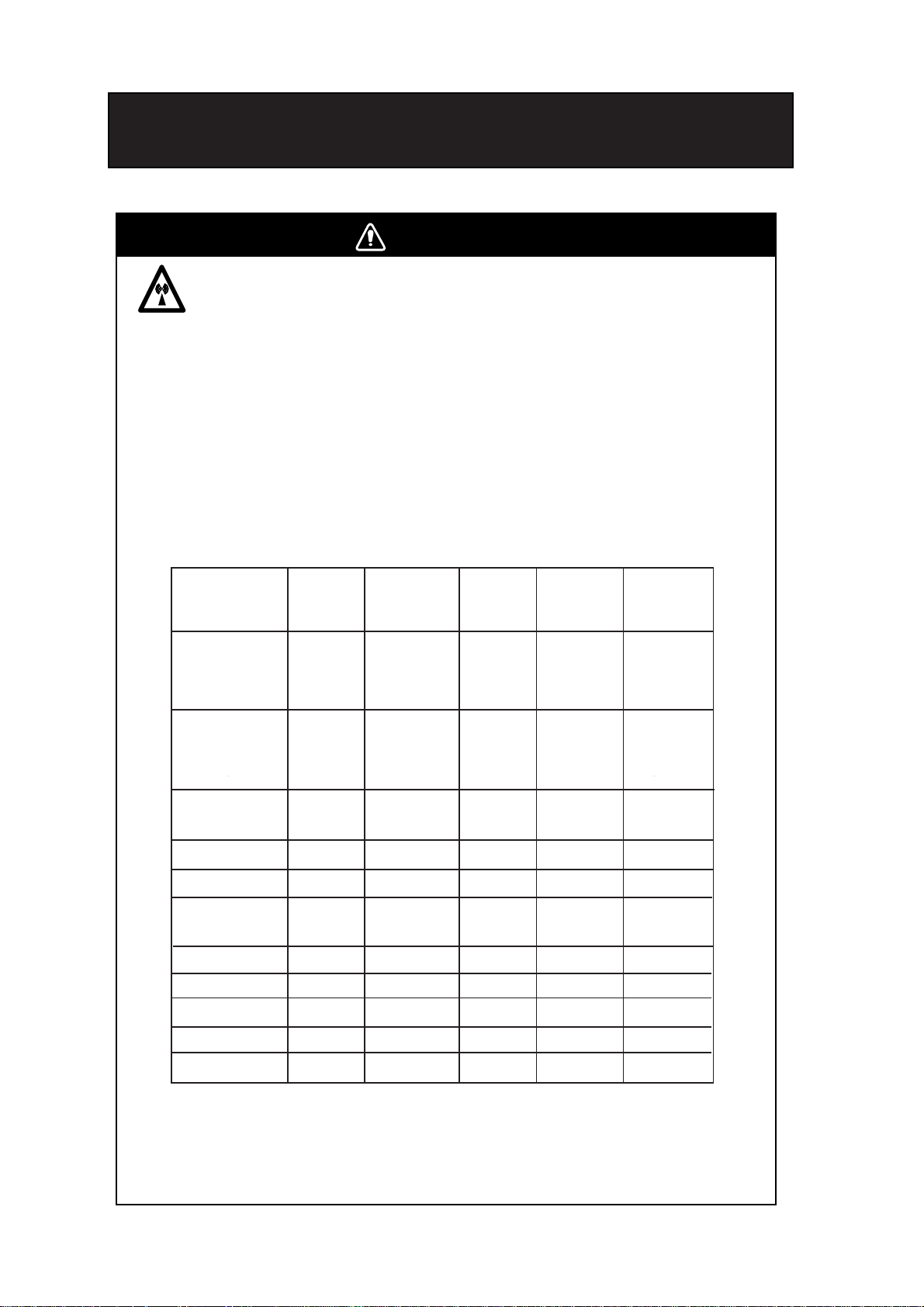
SAFETY INSTRUCTIONS
WARNING
Radio Frequency Radiation Hazard
The radar antenna emits electromagnetic radio frequency (RF) energy which can be
harmful, particularly to your eyes. Never look directly into the antenna aperture from a
close distance while the radar is in operation or expose yourself to the transmitting
antenna at a close distance.
2
Distances at which RF radiation levels of 100 and 10 W/m
below.
Note: If the antenna unit is installed at a close distance in front of the wheel house,
your administration may require halt of transmission within a certain sector of antenna
revolution. This is possible. Ask your FURUNO representative or dealer to provide
this feature.
exist are given in the table
3
Model
FAR-2827/2127 RTR-079 MG5436 XN12AF 0.80 m 11.20 m
FAR-2827/2127 RTR-079 MG5436 XN20AF 0.40 m 8.60 m
FAR-2827/2127 RTR-079 MG5436 XN24AF 0.20 m 5.80 m
FAR-2817/2117 RTR-078 MG4010
FAR-2817/2117 RTR-078 MG4010
FAR-2817/2117 RTR-078 MG4010
FAR-2157 RTR-083 9M31(F) XN4A 1.20 m 13.60 m
XN5A 1.10 m 12.30 m
FAR-2137S RTR-080 MG5223F SN30AF 1.20 m 9.50 m
FAR-2137S RTR-080 MG5223F SN36AF 0.70 m 8.30 m
FAR-2167DS RTR-084 MG5240F SN30AF 0.60 m 8.90 m
SN36AF 0.40 m 7.40 m
FAR-2827W RTR-081 MG5436 XN20AF 2.20 m 13.0 m
FAR-2827W RTR-081 MG5436 XN24AF 1.50 m 11.50 m
FAR-2837S RTR-080 MG5223F SN30AF 1.20 m 9.50 m
TR unit Magnetron Antenna
2
XN12AF 0.30 m 4.20 m
2
XN20AF 0.10 m 3.00 m
2
XN24AF -- 2.40 m
Distance to
1
100 W/m
point
Distance to
2
10 W/m
point
2
ii
FAR-2837S RTR-080 MG5223F SN36AF 0.70 m 8.30 m
FAR-2837SW RTR-082 MG5223F SN36AF 1.00 m 8.50 m
1
XN4A: 8ft XN5A: 10ft XN12AF: 4 ft XN20AF: 6.5 ft XN24AF: 8 ft
SN30AF: 10 ft SN36AF: 12 ft
2
Or MAF1425B
3
FAR-2117/2127/2157/2137S/2167DS available in blackbox configuration.
Page 5
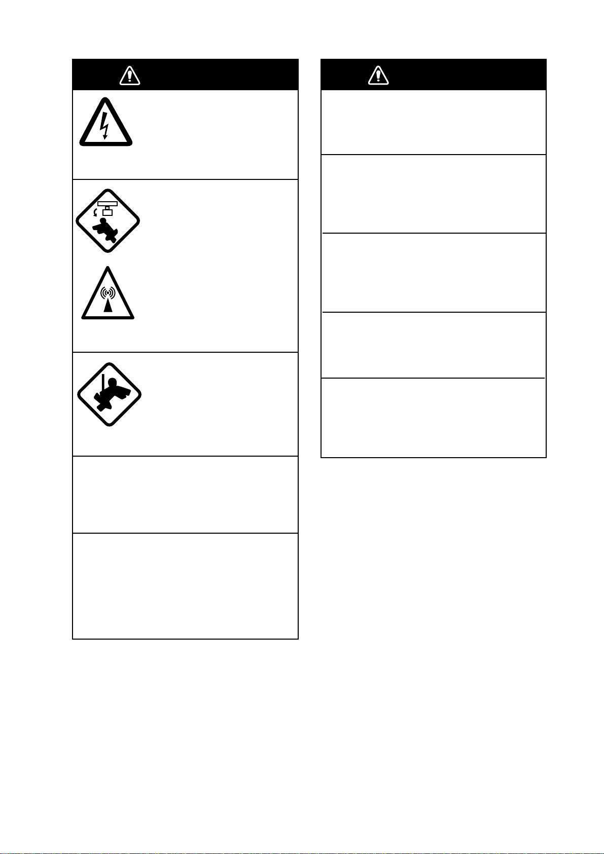
SAFETY INSTRUCTIONS
WARNING
ELECTRICAL SHOCK HAZARD
Do not open the equipment.
Only qualified personnel
should work inside the
equipment.
Turn off the radar power
switch before servicing the
antenna unit. Post a warning sign near the switch
indicating it should not be
turned on while the antenna
unit is being serviced.
Prevent the potential risk of
being struck by the rotating
antenna and exposure to
RF radiation hazard.
Wear a safety belt and hard
hat when working on the
antenna unit.
Serious injury or death can
result if someone falls from
the radar antenna mast.
WARNING
Use the proper fuse.
Use of a wrong fuse can result in damage
to the equipment or cause fire.
Keep heater away from equipment.
Heat can alter equipment shape and melt
the power cord, which can cause fire or
electrical shock.
Do not place liquid-filled containers
near the equipment.
Fire or electrical shock can result if a liquid
spills into the equipment.
Do not operate the equipment with wet
hands.
Electrical shock can result.
Before servicing the radar, turn off
the appropriate external breaker.
Power is not removed from the radar simply
by turning off its power switch.
Do not disassemble or modify the
equipment.
Fire, electrical shock or serious injury can
result.
Immediately turn off the power at the
ship's mains switchboard if water
leaks into the equipment or the equipment is emitting smoke or fire.
Continued use can cause fatal damage to
the equipment.
iii
Page 6
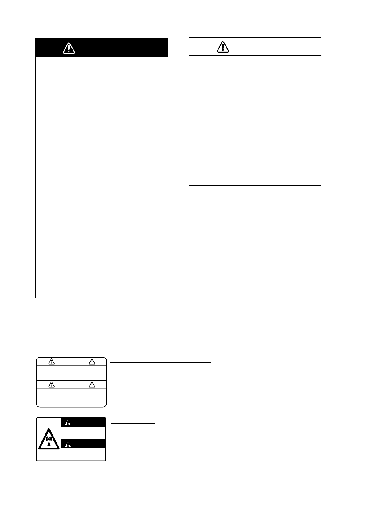
SAFETY INSTRUCTIONS
WARNING
No one navigational aid should be relied
upon for the safety of vessel and crew.
The navigator has the responsibility to
check all aids available to confirm
position. Electronic aids are not
a substitute for basic navigational
principles and common sense.
• This ARP automatically tracks
automatically or manually acquired radar
targets and calculates their courses and
speeds, indicating them by vectors. Since
the data generated by the auto plotter
are based on what radar targets are
selected, the radar must always be
optimally tuned for use with the auto
plotter, to ensure required targets will not
be lost or unwanted targets such as sea
returns and noise will not be acquired
and tracked.
• A target does not always mean a land mass, reef, ships or other surface vessels
but can imply returns from sea surface
and clutter. As the level of clutter changes
with environment, the operator should
properly adjust the A/C SEA, A/C RAIN
and GAIN controls to be sure target
echoes are not eliminated from the
radar screen.
WARNING LABEL
Warning labels are attached to the
equipment. Do not remove any label.
If a label is missing or damaged,
contact a FURUNO agent or dealer
about replacement.
CAUTION
The plotting accuracy and response of
this ARP meets IMO standards.
Tracking accuracy is affected by the
following:
• Tracking accuracy is affected by course
change. One to two minutes is required to
restore vectors to full accuracy after an
abrupt course change. (The actual
amount depends on gyrocompass
specifications.)
• The amount of tracking delay is inversely
proportional to the relative speed of the
target. Delay is on the order of 15—30
seconds for high relative speed; 30—60
seconds for low relative speed.
The data generated by ARP, AIS and
video plotter are intended for
reference only.
Refer to official nautical charts for
detailed and up-to-date information.
WARNING
To avoid electrical shock, do not
remove cover. No user-serviceable
parts inside.
WARNING
Radiation hazard. Only qualified
personnel should work inside scanner.
Confirm that TX has stopped before
opening scanner.
iv
DISPLAY UNIT, PROCESSOR UNIT
Name: Warning Label (1)
Type: 86-003-1011-1
Code No.: 100-236-231
ANTENNA UNIT
Name: Radiation Warning Label
Type: 03-142-3201-0
Code No.: 100-266-890
Page 7

TABLE OF CONTENTS
TABLE OF CONTENTS
FOREWORD ........................................................................................................ xi
PROGRAM NUMBER ........................................................................................ xiv
SYSTEM CONFIGURATION............................................................................... xv
SPECIFICATIONS........................................................................................... SP-1
1.
RADAR OPERATION....................................................................................1-1
1.1 Turning on the Power................................................................................................. 1-1
1.2 Transmitter ON .......................................................................................................... 1-1
1.3 Control Unit................................................................................................................ 1-3
1.4 Main Menu................................................................................................................. 1-5
1.5 Operation Using the On-Screen Boxes...................................................................... 1-7
1.6 Cursor Menu............................................................................................................ 1-10
1.7 Monitor Brilliance ..................................................................................................... 1-11
1.8 Choosing the Display Mode ..................................................................................... 1-12
1.9 On-Screen Boxes and Markers................................................................................ 1-13
1.10 Tuning the Receiver................................................................................................. 1-15
1.10.1 Choosing the tuning method.......................................................................... 1-15
1.10.2 Initializing tuning............................................................................................ 1-15
1.10.3 Automatic tuning ...........................................................................................1-16
1.10.4 Manual tuning................................................................................................ 1-16
1.11 Aligning Heading with Gyrocompass........................................................................ 1-16
1.12 Presentation Modes................................................................................................. 1-17
1.12.1 Choosing presentation mode......................................................................... 1-17
1.12.2 Description of presentation modes ................................................................ 1-18
1.13 Entering Own Ship's Speed ..................................................................................... 1-21
1.13.1 Automatic speed input by log or GPS navigator ............................................ 1-21
1.13.2 Manual speed input....................................................................................... 1-22
1.14 Choosing the Range Scale ...................................................................................... 1-22
1.15 Choosing the Pulselength ........................................................................................ 1-23
1.15.1 Choosing pulselength.................................................................................... 1-23
1.15.2 Changing pulselength.................................................................................... 1-24
1.16 Adjusting the Sensitivity........................................................................................... 1-25
1.17 Suppressing Sea Clutter.......................................................................................... 1-26
1.17.1 Choosing method of adjustment .................................................................... 1-26
1.17.2 Automatic adjustment by the A/C SEA control............................................... 1-26
1.17.3 Manual adjustment of A/C SEA ..................................................................... 1-27
1.18 Suppressing Rain Clutter......................................................................................... 1-28
1.18.1 Turning AUTO RAIN on or off ........................................................................ 1-28
1.18.2 Adjusting A/C RAIN .......................................................................................1-29
1.19 Interference Rejector ............................................................................................... 1-30
1.20 Measuring the Range .............................................................................................. 1-31
1.20.1 Turning range rings on/off..............................................................................1-31
1.20.2 Measuring range by the variable range marker (VRM) .................................. 1-32
1.20.3 Choosing VRM unit of measurement (B, C and W types) .............................. 1-33
1.20.4 TTG to VRM display...................................................................................... 1-33
v
Page 8

SAFETY INSTRUCTIONS
1.21 Measuring the Bearing .............................................................................................1-33
1.21.1 Measuring the bearing ...................................................................................1-33
1.21.2 Choosing true or relative bearing ...................................................................1-35
1.22 Collision Assessment by Offset EBL.........................................................................1-36
1.22.1 How to assess risk of collision by the offset EBL............................................1-36
1.22.2 Choosing point of reference for origin point of offset EBL...............................1-37
1.23 Measuring Range and Bearing Between Two Targets ..............................................1-38
1.24 Setting a Target Alarm ..............................................................................................1-39
1.24.1 How to set a target alarm zone ......................................................................1-39
1.24.2 Acknowledging the target alarm.....................................................................1-40
1.24.3 Deactivating a target alarm ............................................................................1-40
1.24.4 Target alarm attributes ...................................................................................1-41
1.25 Off-Centering the Display .........................................................................................1-42
1.26 Echo Stretch.............................................................................................................1-43
1.27 Echo Averaging ........................................................................................................1-44
1.28 Target Trails..............................................................................................................1-45
1.28.1 True or relative trails ......................................................................................1-45
1.28.2 Trail time........................................................................................................1-46
1.28.3 Trail gradation................................................................................................1-46
1.28.4 Saving, copying target trails ...........................................................................1-47
1.28.5 Trail level .......................................................................................................1-48
1.28.6 Narrow trails (B, C and W types)....................................................................1-48
1.28.7 Longer trails (B, C and W types) ....................................................................1-49
1.28.8 Removing trails from the display temporarily..................................................1-49
1.28.9 Erasing trails..................................................................................................1-49
1.29 Parallel Index Lines..................................................................................................1-50
1.29.1 Displaying, erasing parallel index lines...........................................................1-50
1.29.2 Adjusting index line orientation, index line interval .........................................1-51
1.29.3 Index line bearing reference...........................................................................1-51
1.29.4 Choosing maximum number of index lines to display.....................................1-52
1.29.5 Index line mode .............................................................................................1-52
1.30 Origin Mark ..............................................................................................................1-53
1.30.1 Entering origin marks .....................................................................................1-53
1.30.2 Origin mark stabilization.................................................................................1-55
1.30.3 Deleting individual origin marks .....................................................................1-55
1.31 Zoom........................................................................................................................1-56
1.32 Markers....................................................................................................................1-57
1.32.1 Heading marker and heading line ..................................................................1-57
1.32.2 Stern marker..................................................................................................1-57
1.32.3 North marker..................................................................................................1-57
1.32.4 Own ship symbol ...........................................................................................1-57
1.32.5 Barge marker.................................................................................................1-58
1.33 Automatic Picture Setup According to Navigation Purpose.......................................1-59
1.33.1 Choosing a picture setup option.....................................................................1-61
1.33.2 Restoring default picture setup options ..........................................................1-61
1.33.3 User-programmable picture setups................................................................1-62
1.34 Programming Function Keys ....................................................................................1-64
1.34.1 Activating a function key ................................................................................1-64
1.34.2 Programming the functions keys....................................................................1-64
1.35 Ship’s Position..........................................................................................................1-69
vi
Page 9

TABLE OF CONTENTS
1.36 Noise Rejector ......................................................................................................... 1-70
1.37 Suppressing Second-trace Echoes.......................................................................... 1-71
1.38 Adjusting Brilliance of Screen Data.......................................................................... 1-72
1.39 Watch Alarm ............................................................................................................ 1-73
1.40 Setting Up Nav Data................................................................................................ 1-74
1.41 Text Window Setup .................................................................................................. 1-76
1.42 Customizing Operation ............................................................................................ 1-78
1.43 Alarms ..................................................................................................................... 1-80
1.43.1 Alarm description ..........................................................................................1-80
1.43.2 Outputting alarm signal ................................................................................. 1-82
1.44 Choosing the Antenna, Displaying Antenna Information........................................... 1-83
1.44.1 Choosing the antenna ................................................................................... 1-83
1.44.2 Displaying antenna information ..................................................................... 1-84
1.44.2 Displaying antenna information ..................................................................... 1-84
1.45 Cursor Data............................................................................................................. 1-85
1.46 Performance Monitor ............................................................................................... 1-86
1.46.1 Activating, deactivating the performance monitor .......................................... 1-86
1.46.2 Checking radar performance......................................................................... 1-86
1.47 Wiper....................................................................................................................... 1-88
1.48 Own Ship Symbol .................................................................................................... 1-89
1.49 Color and Brilliance Sets.......................................................................................... 1-90
1.49.1 Choosing color and brilliance set................................................................... 1-90
1.49.2 Presetting color and brilliance set.................................................................. 1-90
1.50 Reference Point for CPA/TCPA................................................................................ 1-91
1.51 Switching Hub HUB-100 (option) ............................................................................. 1-92
1.52 Dual Radar Display............................................................................................... 1-93
1.52.1 Enabling/Disabling the Dual Radar Display ................................................... 1-93
1.52.2 Specifying Sector Width and Length.............................................................. 1-96
1.52.3 Choosing External Radar (image source)...................................................... 1-98
2. RADAR OBSERVATION ............................................................................... 2-1
2.1 General...................................................................................................................... 2-1
2.1.1 Minimum and maximum ranges....................................................................... 2-1
2.2 False Echoes ............................................................................................................. 2-3
2.3 SART (Search and Rescue Transponder).................................................................. 2-5
2.3.1 SART description ............................................................................................ 2-5
2.3.2 Showing SART marks on the radar display ..................................................... 2-6
2.3.3 General remarks on receiving SART ............................................................... 2-7
2.4 RACON ..................................................................................................................... 2-8
3. ARP OPERATION .........................................................................................3-1
3.1 Usage Precautions .................................................................................................... 3-1
3.2 Controls for ARP........................................................................................................ 3-2
3.3 Activating, Deactivating ARP .....................................................................................3-3
3.4 Entering Own Ship's Speed ....................................................................................... 3-3
3.4.1 Echo-referenced speed input .......................................................................... 3-3
3.5 Automatic Acquisition................................................................................................. 3-5
3.5.1 Enabling auto acquisition.................................................................................3-5
3.5.2 Terminating tracking of targets (including reference targets)............................ 3-6
3.6 Manual Acquisition..................................................................................................... 3-7
vii
Page 10

SAFETY INSTRUCTIONS
3.6.1 Setting manual acquisition conditions ............................................................. 3-7
3.6.2 Manually acquiring a target............................................................................. 3-7
3.7 ARP Symbols and ARP Symbol Attributes................................................................. 3-9
3.7.1 ARP symbols .................................................................................................. 3-9
3.7.2 Choosing ARP symbol (B, C and W types).....................................................3-10
3.7.3 ARP symbol brilliance ....................................................................................3-10
3.7.4 ARP symbol color and size ............................................................................3-11
3.7.5 Auto target track (A, B, C and W types) .........................................................3-12
3.8 Displaying Target Data .............................................................................................3-13
3.8.1 Displaying individual target data.....................................................................3-13
3.8.2 Target list .......................................................................................................3-15
3.9 Vector Modes ...........................................................................................................3-17
3.9.1 Description of vectors ....................................................................................3-17
3.9.2 Vector motion and length ...............................................................................3-18
3.10 Past Position Display................................................................................................3-19
3.10.1 Displaying and erasing past position points, choosing past position
plot interval ....................................................................................................3-19
3.10.2 Past position display attributes.......................................................................3-20
3.11 Set and Drift .............................................................................................................3-21
3.12 Setting CPA/TCPA Alarm Ranges.............................................................................3-22
3.12.1 Setting CPA/TCPA alarm ranges....................................................................3-22
3.12.2 Acknowledging CPA/TCPA alarm...................................................................3-23
3.13 Setting a Guard Zone...............................................................................................3-24
3.13.1 Activating the guard zone...............................................................................3-24
3.13.2 Sleeping, deactivating a guard zone ..............................................................3-25
3.13.3 Acknowledging the guard zone alarm ............................................................3-25
3.13.4 Guard zone reference....................................................................................3-26
3.13.5 Guard zone shape and stabilization ...............................................................3-26
3.14 Operational Warnings...............................................................................................3-27
3.15 Trial Maneuver .........................................................................................................3-29
3.15.1 Types of trial maneuvers................................................................................3-29
3.15.2 Performing a trial maneuver...........................................................................3-30
3.15.3 Terminating a trial maneuver..........................................................................3-32
3.16 ARP Performance Test .............................................................................................3-33
3.17 Criteria for Selecting Targets for Tracking .................................................................3-35
3.18 Factors Affecting ARP Functions ..............................................................................3-37
4. AIS OPERATION...........................................................................................4-1
4.1 Controls for AIS ......................................................................................................... 4-1
4.2 Enabling/Disabling the AIS ........................................................................................ 4-2
4.3 Turning AIS Display On/Off........................................................................................ 4-3
4.4 Setting Up for a Voyage ............................................................................................ 4-4
4.5 Activating Targets...................................................................................................... 4-6
4.5.1 Activating specific target ................................................................................. 4-6
4.5.2 Activating all targets........................................................................................ 4-6
4.6 Sleeping Targets........................................................................................................ 4-7
4.6.1 Sleeping an AIS target .................................................................................... 4-7
4.6.2 Sleeping all AIS targets................................................................................... 4-7
4.7 Displaying Target Data .............................................................................................. 4-8
4.7.1 Basic data....................................................................................................... 4-8
viii
Page 11

TABLE OF CONTENTS
4.7.2 Detailed target data ......................................................................................... 4-9
4.8 AIS Symbol Attributes.............................................................................................. 4-10
4.8.1 AIS symbol brilliance..................................................................................... 4-10
4.8.2 AIS symbol size and color ............................................................................. 4-11
4.9 Past Position Display ............................................................................................... 4-12
4.9.1 Displaying and erasing past position points, choosing past position
plot interval.................................................................................................... 4-12
4.9.2 Past position display attributes ...................................................................... 4-13
4.10 Lost Target............................................................................................................... 4-14
4.11 ROT Setting............................................................................................................. 4-15
4.12 Fusion of ARP and AIS Targets................................................................................ 4-16
4.13 Own Ship’s Data...................................................................................................... 4-18
4.14 Messages................................................................................................................ 4-19
4.14.1 Creating, saving a message.......................................................................... 4-19
4.14.2 Transmitting a message ................................................................................ 4-20
4.14.3 Viewing AIS messages.................................................................................. 4-21
4.15 AIS System Messages............................................................................................. 4-23
5. VIDEO PLOTTER OPERATION....................................................................5-1
5.1 General...................................................................................................................... 5-1
5.2 Display Modes ........................................................................................................... 5-1
5.3 Presentation Modes ................................................................................................... 5-2
5.4 Radar Map................................................................................................................. 5-3
5.4.1 Turning on the radar map display .................................................................... 5-3
5.4.2 Inscribing radar map marks and lines.............................................................. 5-4
5.5 Erasing Radar Map Marks and Lines ......................................................................... 5-6
5.5.1 Erasing individual radar map marks and lines .................................................5-6
5.5.2 Erasing all radar map marks and lines............................................................. 5-7
5.6 Radar Map Corrections.............................................................................................. 5-8
5.6.1 Radar map correction...................................................................................... 5-8
5.6.2 Cursor data correction..................................................................................... 5-8
5.7 Chart Cards (B, C and W types) ................................................................................ 5-9
5.7.1 Displaying a chart............................................................................................ 5-9
5.7.2 Chart position correction................................................................................ 5-10
5.7.3 Correcting cursor data................................................................................... 5-10
5.7.4 Chart land color............................................................................................. 5-11
5.8 Hiding/Showing Graphics on the Video Plotter Display.......................................... 5-12
5.9 Track ....................................................................................................................... 5-13
5.9.1 Plotting own ship’s track................................................................................ 5-13
5.9.2 Plotting other ships’ track (A, B, C and W types) ........................................... 5-14
5.9.3 Choosing track color...................................................................................... 5-14
5.9.4 Erasing track ................................................................................................. 5-15
5.10 Marks and Lines ...................................................................................................... 5-16
5.10.1 Inscribing marks and lines ............................................................................. 5-16
5.11 Erasing Marks and Lines ......................................................................................... 5-18
5.11.1 Erasing individual marks/lines ....................................................................... 5-18
5.11.2 Erasing all marks and lines............................................................................ 5-19
5.12 Waypoints................................................................................................................ 5-20
5.12.1 Entering waypoints ........................................................................................ 5-20
5.12.2 Editing, erasing waypoints from the menu..................................................... 5-23
ix
Page 12

SAFETY INSTRUCTIONS
5.12.3 Erasing waypoints..........................................................................................5-24
5.12.4 Waypoint list ..................................................................................................5-25
5.12.5 Displaying waypoint name and number..........................................................5-26
5.13 Nav Lines.................................................................................................................5-27
5.13.1 Entering new nav line.....................................................................................5-27
5.13.2 Editing nav lines.............................................................................................5-28
5.13.3 Nav line list ....................................................................................................5-29
5.13.4 Erasing nav lines ...........................................................................................5-30
5.13.5 Setting up nav lines........................................................................................5-31
5.13.6 Displaying nav line, waypoint mark ................................................................5-33
5.14 Recording Data ........................................................................................................5-35
5.14.1 Initializing memory (RAM) cards ....................................................................5-35
5.14.2 Recording data ..............................................................................................5-36
5.15 Replaying Data.........................................................................................................5-38
5.16 Deleting Files ...........................................................................................................5-39
6. MAINTENANCE, TROUBLESHOOTING...................................................... 6-1
6.1 Periodic Maintenance Schedule ................................................................................ 6-2
6.2 Life Expectancy of Major Parts.................................................................................. 6-3
6.3 Replacing the Fuse ................................................................................................... 6-3
6.4 Replacement of Battery on GC Board ....................................................................... 6-4
6.5 Trackball Maintenance .............................................................................................. 6-4
6.6 Easy Troubleshooting................................................................................................ 6-5
6.7 Advanced-level Troubleshooting................................................................................ 6-6
6.8 Diagnostics ............................................................................................................... 6-9
6.9 System Messages....................................................................................................6-12
APPENDIX ......................................................................................................AP-1
1. Menu Tree ...................................................................................................................AP-1
2. Digital Interface............................................................................................................AP-8
3. Parts Lists and Parts Location ................................................................................... AP-29
4. Longitude Error Table (on 96 nm range scale)...........................................................AP-45
INDEX............................................................................................................... IN-1
Declaration of Conformity
x
Page 13

FOREWORD
A Word to the Owner of the FAR-28x7/FAR-21x7(-BB)
Congratul ations on your c hoice of the FURUNO FAR-28x7/FA R-21x 7( -BB) Seri es Radar.
We are conf ident you w ill see why FURUNO has become synonymous w ith quality and
reliability.
For over 50 y ears FURUNO Elec tric Company has enjoyed an en vi able reput ation for
innovati ve a nd dependabl e m ar ine electronics equipment. Thi s dedic ation to excel lence is
furthered by our extensi ve gl obal network of agents and dealers.
Your radar is designed and constructed to meet the rigorous demands of the m ar ine
environme nt. However, no machine can perform its int ended function unless installed,
operated an d m aintained pr operly. Please carefully r ead and follow the recom m ended
procedures f or operation and maintenanc e.
We would appreciate hearing from you, the end-user, about whether w e ar e achieving our
purposes.
Thank you for considering and purchasing FURUNO equipment.
Note: The example sc r eens shown in t his manual may not m atch the screens you see on
your dis play. The scr een you see depends o n your system configurat ion and
equipment s ettings.
Features
• High-res olution 20.1-inch LCD (FR-21x7) or 23.1-inch LCD (FR-28x7).
• This s eries of radar and ARP ( automatic radar plotter, includes ARPA or A TA) are
available in the models shown in the table below. “BB” means blackbox conf iguration
(monitor t o be s upplied locally) is avail able.
X-band S-band
Model Output
FAR-2117(-BB) 12 kW
FAR-2127(-BB) 25 kW
FAR-2157(-BB) 50kW
FAR-2817 12 kW
FAR-2827 25 kW
FAR-2827W 25 kW
TR config.
UP
UP
UP
UP
UP
DOWN
Output
Model
FAR-2137S(-BB) 30 kW
FAR-2167DS(-BB) 60 kW
FAR-2837S 30 kW
FAR-2837SW 30 kW
TR config.
UP
UP
UP
DOWN
xi
Page 14

FOREWORD
• Two ty pes of trackball-equipped control units are avai lable: RCU-01 4 ( full keyboard) and
the RCU-015 (palm cont r ol). The trackball is eas y to use thanks to the er gonomically
designed palm rest.
• Simplified operation with point - and- c lick menu o per ation.
• All f unc tions are accessible by using the trackbal l alone.
• Applicable to HSC (High Speed Craft)
• ARPA (Automatic Radar Plotting Aid) or ATA (Automatic Tracking Aid) + AIS, Radar P lotter
and Interswitch supplied as standard. ( A RPA or ATA selectable on inst allation menu.)
• Meets the foll owing requirements:
IMO MSC. 64( 67) Annex 4: Performance standards for Radar equipment
IEC 60936-1 (1999): Shipborne radar-Performance r equirements
IEC 60936-1 Am. 1 ( 2002-06): Unwanted emissions of radar sy stems
IMO A.823 (19): Performance standards for ARPAs
IEC 60872-1 (1998): ARPA – Perfor m ance requir em ents
IMO A.820(19): Performanc e s tandards f or navigational radar equipment for high speed
craft
IEC 60936-2 (1998): Radar f or high speed craft – Performance requirem ents
IMO A. 694(17): G eneral requir em ents for electronic navigational aids ( including ATA)
IEC 60945 (2002-08): Maritime Navigat ional Equipment General Requirements
IEC 61162-1 and 2: Marit ime navigation equipment-di gital interface
IEC 60936-5: Guidelines for the use and displ ay of AIS infor mation on Radar
IEC 60872-2: ATA performanc e r equirements
• Guard al ar m watches f or targets entering or exiting the guard zone
• TCPA/CPA alarms
• Electronic parallel index lines
• 42 rpm antenna for high sp eed craft
Compliance with MED and R&TTE Directive
This radar com piles wit h M E D 96/98/EC and its amendment 2002/75/EC of S eptember 2,
2002 and also complies with the R&TT E Direc tive 1999/5/EC. In accordance with Article 6-3
of the above-mentioned R&TTE dir ec tive, FURUNO intends to put thi s r adar on the market
of the fol lowing countri es in EU as well other mar k ets: Austria, Belgium, Cyprus, Denmark,
Estonia, Finland, France, Germany, G r eec e, Hungary, Ireland, Italy, Latvia, Lithuani a, Malta,
Poland, Portugal, Slove nia, S pain, Sw eden, The Netherlands, United Kingdom, Iceland,
Norway
xii
Page 15

FOREWORD
Radar Type and Function Availability
This radar series is available in five specification types to meet the requirements of Authorities,
and function availability depends on specification type. The table below shows those functions
which have limited availability. This manual provides descriptions for all functions in this radar
series, and we have endeavored to denote in the text those functions which have limited
availability. For detailed information on function availability, see the menu tree in the Appendix.
• IMO: IMO compliant
• A: Near-IMO specifications
• B: Non-Japanese fishing vessels
• C: Japanese fishing vessels
• W: Washington state (USA) ferry
Specification type and function avai lability
Function
Type
IMO A B C W
ARP symbol
selection
ARP w/o
gyro
Alarm zone
range
limitation
Chart display No No Yes Yes Yes
Color echo No Yes Yes Yes Yes
Dual radar No No Yes Yes Yes
Mark w/line No No Yes Yes Yes
Pop-up
guidance
Range 0.125, 0.25,
Range unit nm only nm only nm, sm, km,
Stern-up
mode
VRM unit km No No Yes Yes Yes
Track-Other
Ship
Trails-Narrow No No Yes Yes Yes
WPT marker No No Yes Yes Yes
No No Yes Yes Yes
No No Yes Yes Yes
Yes No No No No
No No Yes Yes Yes
Same as IMO 0.125, 0.25,
0.5, 0.75, 1.5,
3, 6, 12, 24,
48, 96
No No Yes Yes Yes
No Yes Yes Yes Yes
0.5, 0.75, 1, 2,
1.5, 3, 4, 6, 8,
12, 16, 24, 32,
48, 96, 120
kyd
Same as B Same as B
nm, sm, km,
kyd
nm, sm, km,
kyd
xiii
Page 16

PROGRAM NUMBER
PC Board Program No. Version No.
MAIN 035-9204 02.** (Merchant) / 50.** (Fishing)
RFC 035-9202 01.**
KEY(REMOTE) 035-9203 01.**
ARPA 035-9212 01.**
** Minor m odification
xiv
Page 17
v
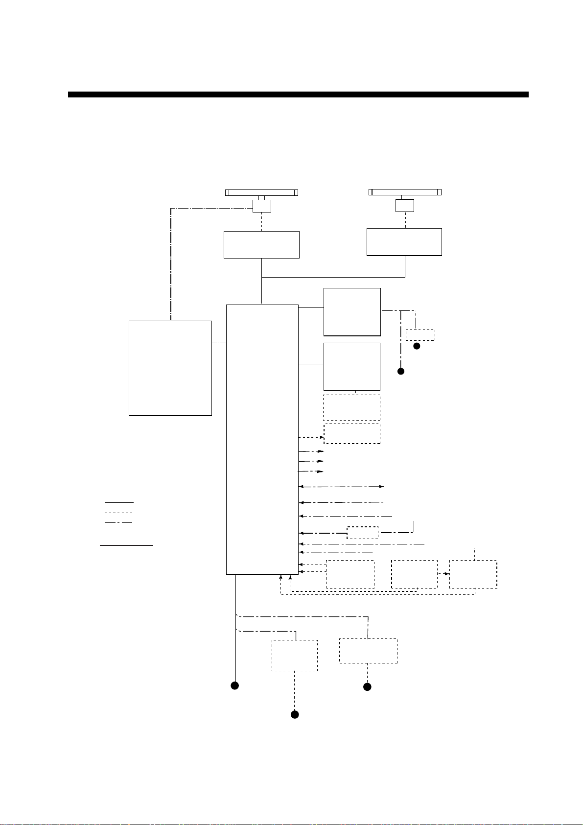
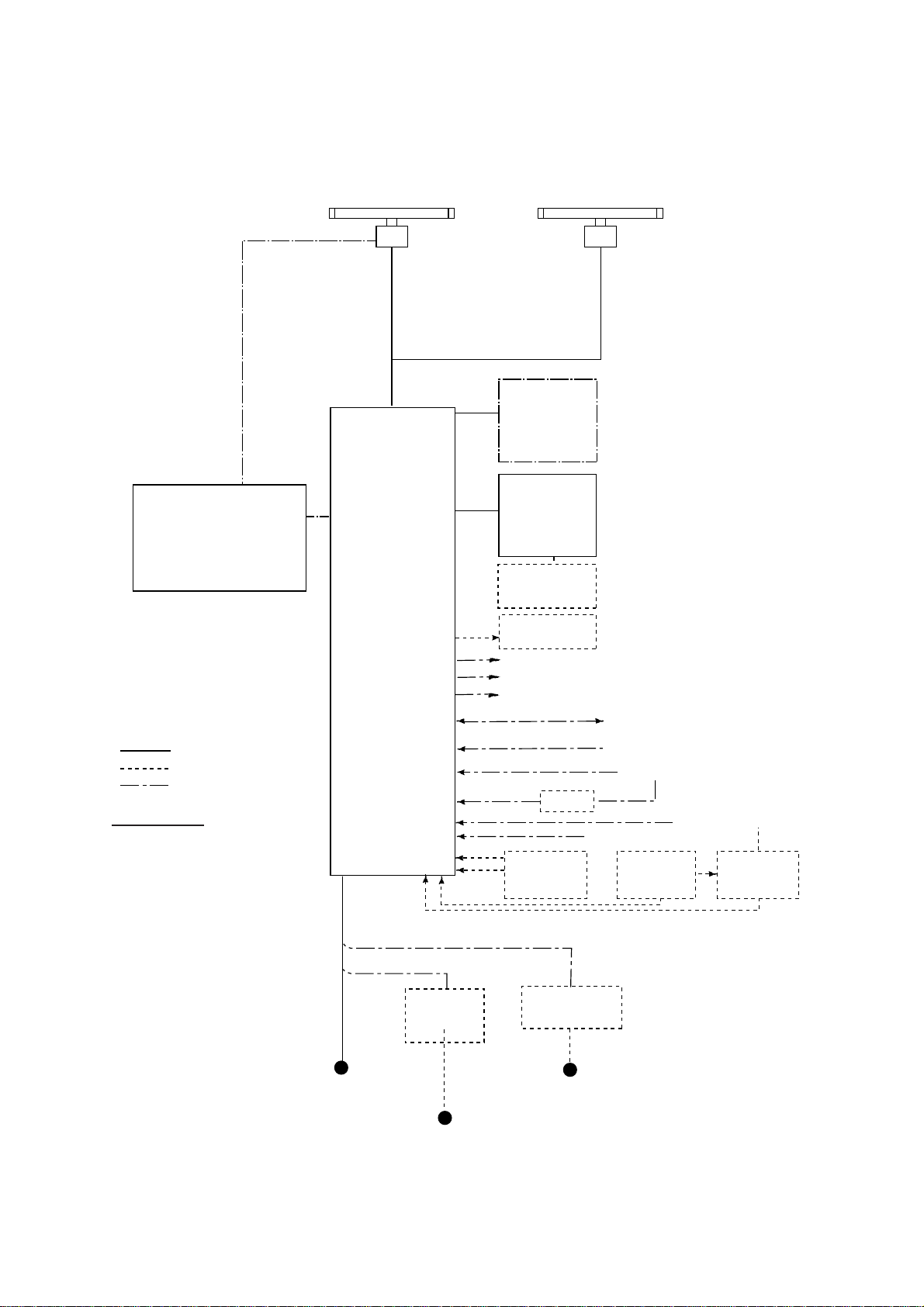
SYSTEM CONFIGURATION
See page xvi for detailed informat ion about antenna units and radi ators.
With FURUNO-supplied monitor
FAR-2137S/2167DS/2837S/2837SW
* Neither FAR-2157 nor
FAR-2167DS carry a
performance monitor.
POWER SUPPLY UNIT
PSU-006
(For FAR-2157/2167DS)
(For FAR-2137S/2837S)
(For FAR-2827W/2837SW)
* Russian flag only
OR
POWER SUPPLY UNIT
PSU-007
OR
POWER SUPPLY UNIT
PSU-011*
(Performance Monitor PM-51* built in)
ANTENNA UNIT
Waveguide or
Coax cable
(For FAR-2837SW)
TRANSCEIVER UNIT
RTR-082
For FAR-2837SW
PROCESSOR UNIT
RPU-013
FAR-2117/2127/2157/2817/2827/2827W
(Performance Monitor PM-31* built in)
MONITOR UNIT
MU-201CR
(FAR-21x7)
or
MU-231CR
(FAR-28x7)
CONTROL UNIT
RCU-014
(Keyboard)
or
RCU-015
(Trackball)
Control Unit
RCU-016
(Remote)
Sub Display
ANTENNA UNIT
Waveguide
(For FAR-2827W)
TRANSCEIVER UNIT
RTR-081
For FAR-2827W
24 VDC
RU-3423
115/230 VAC
24 VDC
or
115/230 VAC
: Standard
: Option
: Dockyard supply
Category of Units
Antenna unit: Exposed to weather
All other units: Protected from weather
Alarm
VDR
External Monitor
IEC-61162-1 Serial Data
(Input/Output)
IEC-61162-1 Serial Data
(Input)
AD-100
Memory Card
Interface Unit
CU-200
HUB has ports for connection of up to 7 processor units
DC spec
24 VDC
or
100-115 VAC/
220-230 VAC
1φ, 50/60 Hz
Rectifier
RU-3424
RU-1746B-2
100/110/115/
220/230 VAC
1φ, 50/60 Hz
Transformer Unit
RU-1803
1φ, 50/60 Hz
Navigator (INS, GPS, etc.)
Speed Log
Track Control Unit
OR
AC spec
440 VAC
Gyrocompass
Memory Card
Interface Unit
CU-200 x 2
AIS
100-230 VAC
Switching Hub
HUB-100
x
Page 18

SYSTEM CONFIGURATION
Antenna unit
FAR-2117,
FAR-2117-BB,
FAR-2127,
FAR-2127-BB,
FAR-2827
FAR-2137S,
FAR-2137S-BB
FAR-2157,
FAR-2157-BB
FAR-2167DS,
FAR-2167DS-BB
FAR-2827W RSB-103 (24 rpm, powered by processor unit)
FAR-2837S Same as FAR-2137S
FAR-2837SW RSB-104/105 (21/26 rpm, 200 VAC, 3ø, 50 Hz; 220 VAC, 3ø, 60 Hz; 380
RSB-096 (24 rpm)
RSB-097 (42 rpm)
RSB-098/099 (21/26 rpm, 200 VAC, 3ø, 50 Hz; 220 VAC, 3ø, 60 Hz; 380
VAC, 3ø, 50 Hz, 440 VAC, 3ø, 60 Hz)
RSB-100/101/102 (45 rpm, 220 VAC, 3ø, 50/60 Hz(HSC);
440 VAC, 3ø, /60 Hz(HSC))
RSB-106 (18/22 rpm, 200 VAC, 3ø, 50 Hz; 220 VAC, 3ø, 60 Hz)
RSB-107 (22 rpm, 24 VDC)
RSB-111 (21/26 rpm, 200 VAC, 3ø, 50 Hz; 220 VAC, 3ø, 60 Hz)
RSB-112 (21/26 rpm, 380 VAC, 3ø, 50 Hz, 440 VAC, 3ø, 60 Hz)
VAC, 3ø, 50 Hz, 440 VAC, 3ø, 60 Hz)
Radiator
FAR-2117, FAR-2117-BB,
FAR-2127, FAR-2127-BB,
FAR-2827
FAR-2157, FAR-2157-BB XN4A (8 ft), XN5A (10 ft)
FAR-2137S, FAR-2137S-BB,
FAR-2167DS, FAR-2167DS-BB
FAR-2827W XN20AF (6.5 ft), XN24AF (8 ft)
FAR-2837S SN30AF (10 ft), SN36AF (12 ft)
FAR-2837SW SN30AF (10 ft), SN36AF (12 ft)
XN12AF (4 ft), XN20AF (6.5 ft),
XN24AF (8 ft)
SN30AF (10 ft), SN36AF (12 ft)
xvi
Page 19
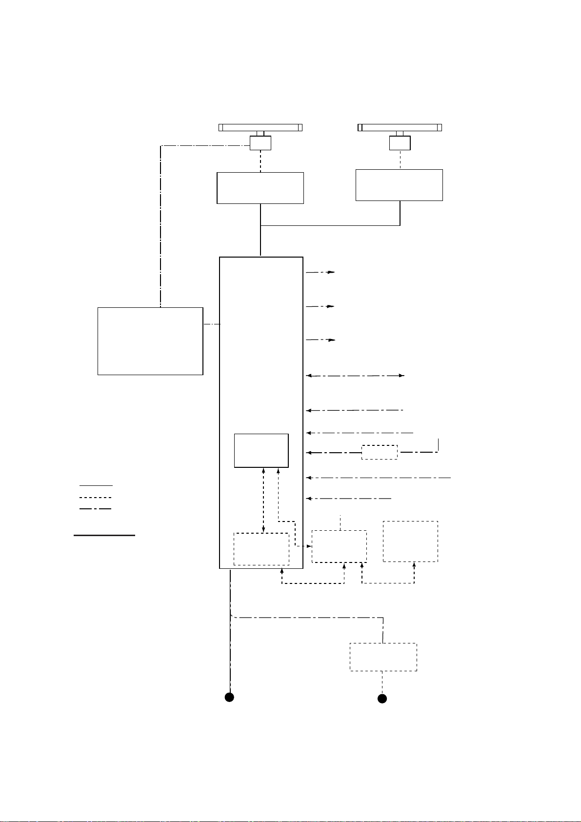
SYSTEM CONFIGURATION
Blackbox type
* Neither FAR-2157-BB nor
FAR-2167DS-BB carry a
performance monitor.
POWER SUPPLY UNIT
PSU-006
(For FAR-2157-BB/2167DS-BB)
OR
POWER SUPPLY UNIT
PSU-007
(For FAR-2137S-BB/2837S-BB)
FAR-2137S-BB/FR-2167DS-BB
ANTENNA UNIT
(Performance Monitor PM-51 built in
FAR-2137S-BB)
PROCESSOR UNIT
RPU-013
FAR-2117-BB/2127-BB/FAR-2157-BB
ANTENNA UNIT
(Performance Monitor PM-31 built in
FAR-2117-BB, FAR-2127-BB)
VGA
MONITOR
CONTROL UNIT
RCU-014
(Keyboard)
or
RCU-015
(Trackball)
Control Unit
RCU-016
(Remote)
Sub Display
: Standard
: Option
: Dockyard supply
Category of Units
Antenna unit: Exposed to weather
All other units: Protected from weather
HUB has ports for connection of up to 7 processor units
24 VDC
or
100-115 VAC/
220-230 VAC
1φ, 50/60 Hz
DC spec
Rectifier
RU-3424
RU-1746B-2
100/110/115/
220/230 VAC
1φ, 50/60 Hz
Alarm
VDR
External Monitor
IEC-61162-1 Serial Data
(Input/Output)
IEC-61162-1 Serial Data
(Input)
AD-100
Memory Card
Interface Unit
CU-200
AC spec
Transformer Unit
RU-1803
440 VAC
1φ, 50/60 Hz
Navigator (INS, GPS, etc.)
Speed Log
Gyrocompass
Track Control Unit
OR
Memory Card
Interface Unit
CU-200 x 2
AIS
100-230 VAC
Switching Hub
HUB-100
xvii
Page 20
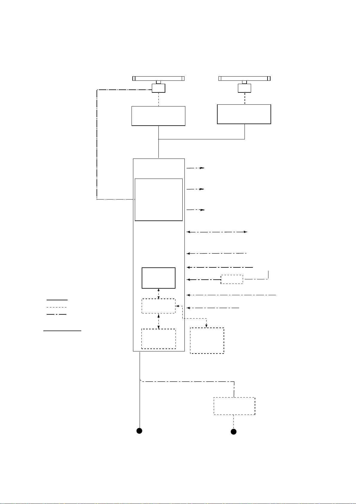
SYSTEM CONFIGURATION
Console type RCN-001/RCN-002
POWER SUPPLY UNIT
PSU-007
For FAR-2137S/2837S
OR
POWER SUPPLY UNIT
PSU-011*
(For FAR-2827W/2837SW)
* Russian flag only
FAR-2137S/2837S/2837SW
ANTENNA UNIT
(Performance Monitor PM-51 built in)
Waveguide or
Coax cable
(For FAR-2837SW)
TRANSCEIVER UNIT
RTR-082
For FAR-2837SW
CONSOLE
RCN-001/002
FAR-2117/2127/2817/2827/2827W
(Performance Monitor PM-31 built in)
Alarm
VDR
External Monitor
IEC-61162-1 Serial Data
(Input/Output)
ANTENNA UNIT
Waveguide
(For FAR-2827W)
TRANSCEIVER UNIT
RTR-081
For FAR-2827W
Navigator (INS, GPS, etc.)
: Standard
: Option
: Dockyard supply
Category of Units
Antenna unit: Exposed to weather
All other units: Protected from weather
PROCESSOR
RPU-013
May also
be installed
externally.
Memory Card
Interface Unit
CU-200
UNIT
OR
IEC-61162-1 Serial Data
(Input)
AD-100
100-230 VAC
Switching Hub
HUB-100
Transformer Unit
RU-1803
Speed Log
Gyrocompass
AIS
Track Control Unit
Memory Card
Interface Unit
CU-200
(Max. 2 total)
AC spec
xviii
100-115 VAC/
220-230 VAC
1φ, 50/60 Hz
440 VAC
1φ, 50/60 Hz
Page 21
Console type RCN-003/RCN-004
SYSTEM CONFIGURATION
FAR-2137S/2837S/2837SW
ANTENNA UNIT
(Performance Monitor PM-51 built in)
Waveguide or
Coax cable
(For FAR-2837SW)
TRANSCEIVER UNIT
RTR-082
For FAR-2837SW
CONSOLE
RCN-003/004
POWER SUPPLY UNIT
PSU-007
For FAR-2137S/2837S
OR
POWER SUPPLY UNIT
PSU-011*
(For FAR-2827W/2837SW)
* Russian flag only
FAR-2117/2127/2817/2827/2827W
(Performance Monitor PM-31 built in)
Alarm
VDR
External Monitor
IEC-61162-1 Serial Data
(Input/Output)
ANTENNA UNIT
Waveguide
(For FAR-2827W)
TRANSCEIVER UNIT
RTR-081
For FAR-2827W
Navigator (INS, GPS, etc.)
: Standard
: Option
: Dockyard supply
Category of Units
Antenna unit: Exposed to weather
All other units: Protected from weather
PROCESSOR
UNIT
RPU-013
Switching Hub
HUB-100
Memory Card
Interface Unit
CU-200
IEC-61162-1 Serial Data
(Input)
AD-100
Memory Card
Interface Unit
CU-200
(Max. 2 total)
AC spec
Transformer Unit
RU-1803
Speed Log
Gyrocompass
AIS
Track Control Unit
100-115 VAC/
220-230 VAC
1φ, 50/60 Hz
440 VAC
1φ, 50/60 Hz
xix
Page 22

SYSTEM CONFIGURATION
(This page intenti onally left blank. )
xx
Page 23

FURUNO
SPECIFICATIONS OF MARINE RADAR/ARPA
FAR-21x7(-BB)/28x7 SERIES
1. ANTE N NA RADI ATORS
1. Type Slotted waveguide array
2. Beam width and sidelo be attenuation
FAR-21x7(-BB)/28x7 SERIES
Radiator type
XN4A XN5A
X-band S-band
XN12AF XN20AF XN24AF SN30AF SN36AF
Length 8 ft 10 ft 4 ft 6.5 ft 8 ft 10 ft 12 ft
Beam width(H) 0.95° 0.75° 1.8° 1.23° 0.95° 2.3° 1.8°
Beam width(V) 20° 20° 20° 20° 20° 25° 25°
Sidelobe within ±10° -28 db -26 db -24 db -28db -28 db -24 db -24 db
Sidelobe outside ±10°
-32 db -30 db -30 db -32 db -32 db -30 db -30 db
3. Polarization Horizontal
4. Rotation FAR-2117/2117-BB/2127/2127-BB/2827: 24 rpm or 42 rp m
FAR-2157/2157-BB: RSB-106, 18 rpm (50 Hz)/22 rpm (60 Hz ),
RSB-107, 22 rpm
FAR-2137S/2137S-B B/2837S: 21 rpm (50 Hz)/26 rpm (60 Hz)/
45 rpm (HSC)
FAR-2167DS/2167DS-BB/2837SW: 21 rpm (50 Hz)/26 rp m (60 Hz )
FAR-2827W: 24 rpm
5. De-icer (option) On: When temperature goes down to +5°C
Off: When temperature goes up to +12° C
2. RF TRANSCEIVER
1. Frequency X-band: 9410 MHz ±30 MHz, S-band: 3050 MHz ±30 MHz
2. Output power FAR-2117/2117-BB/2817: 12 kW
FAR-2127/2127-BB/2827/2827W: 25 kW
FAR-2137S/2137S-BB/2837S/2837SW: 30 kW
FAR-2157/2157-BB: 50 kW
FAR-2167DS/2167DS-BB: 60 kW
Unwanted emissions comply wit h ITU-R RR.
3. Pulselength, PL, P RF a nd range
X- band 12 kW and 25 kW models
Pulselength S1 S2 M1 M2 M3 L
PL (µs) 0.07 0.15 0.3 0.5 0.7 1.2
PRF (Hz) 3000* 3000* 1500 1000 1000 600**
Range scale
(nm)
0.125,
0.25, 0.5,
0.75, 1
1.5, 2
#
,
#
0.5, 0.75,
#
1
, 1.5, 2#,
#
3, 4
0.75, 1
1.5, 2
4
#
, 6, 8#
#
, 3,
#
,
3, 4
#
8
, 12,
16
#
#
, 24
, 6,
3, 4
#
8
16
#
, 6,
, 12,
#
, 24
6, 8
16
32
#
, 12,
#
, 24,
#
, 48,
96, 120
*: 2200 Hz with ARPA on, 32 nm range **: 500 Hz on 96 and 120 nm ranges #: Non-IMO type only
X- band 50 kW and S-band 60 kW models
Pulselength S M1 M2 L
PL (µs) 0.08 0.2 0.6 1.2
PRF (Hz) 1900 1100 600 600**
Range scale
(nm)
0.125,
0.25, 0.5,
0.75, 1,
1.5, 2, 3, 4
0.75, 1,
1.5, 2
**: 500 Hz on 96 and 120 nm ranges
3, 4, 6, 8,
12, 16, 24
6, 8, 12,
16, 24, 32,
48, 96,
120
4. IF 60 MHz
5. Noise figure 6 dB (typical)
#
SP - 1 E3519S01L-M
Page 24

FURUNO
FAR-21x7(-BB)/28x7 SERIES
6. Duplexer Ferrite circu lator with diode limiter for
FAR-2117/2117-BB/2127/2127-BB/2137S/2137S-BB/2157/2157-BB/
2167DS/2167DS-BB/2817/2827/2827W/2837S
Ferrite circulator with TR limiter for FAR-2837SW
3. DISPLAY UNIT
1. Screen Yellow or green echoes in 32 levels. Rasterscan non-interlace at 64
kHz horizontal, 60 Hz vertical. Non-IMO type has yellow or green
monochrome plus 3-color display according to echo strengths.
FAR-21x7 series FAR-28x7 series
Size, model 20.1-inch color LCD, MU-201CR 23.1-inch color LCD, MU-231CR
Display area (mm) 399.36 x 319.49 470.4 x 352.8
Resolution 1280 x 1024 pixels 1600 x 1200 pixels
Effective radar diameter 308 mm (H: 64 kHz, V: 60 Hz) 340 mm (H: 75 kHz, V: 60 Hz)
2. Minimum range and Minimum range: 20 m w/raw video, + 0-2 m w/digitize error
range discrimination Range discrimination: 20 m w/raw video, + 0-6 m w/digitize error
3. Range scales (nm), 0.125 (.025), 0.25 (0.05), 0.5 (0.1), 0.75 (0.25), 1 (0.25)*, 1.5 (0.25),
ring interval 2 (0.5)*, 3 (0.5), 4 (1)*, 6 (1), 8 (2)*, 12 (2), 16 (4)*, 24 (4), 32 (8)*, 48
(8), 96 (16), 120 (20)* *: Non-IMO type only
4. Range accuracy Within 1%
5. Bearing discrimination 0.95° (XN4A), 0.75° (XN5A), 2.1° (XN12AF), 1.5° (XN20A F), 1. 2°
(XN24AF), 2.5° (SN30AF), 2.0° (SN36AF)
6. Bearing accuracy ±1°
7. Presentation mode Head-up, Hea d-up TB, North-up, Course-up, True Motion sea or
ground stabilization
8. Plotting facilities
(ARPA or ATA) Auto tracking on all acquired targets
9. Radar map Nav lines, coastlines, b uoys, etc. produced by operator. 20,000 pts
10. Guard zone GZ1: 0.5 nm width sector, within 3-6 nm, desired bearing
11. Parallel index line Choice of 2, 4 or 6 lines
12. AIS IMO SN Circ.217, IEC/PAS 60936-5
13. Chart cards FURUNO and NAVIONICS
Auto or Manual acquisition: 100 targets in 0.1-32 nm
in radar mode, 6000 pts on IC card in chart mode
GZ2: 1 nm width sector or polygon, desired range and bearing
4. INTERFACE
1. IEC 61162-1 Ed. 2 RSD, TTM, AIS related data, etc.
2. Compass Built-in interface (option) for sync signal (20-135 V, 50-400 Hz), or
stepper signal (20-135 VDC), any polarity, for gyrocompass, G PS
compass SC-60/120 by IEC 61162-2
3. Speed log NMEA format data
4. Others Echo sounder, GPS navig at or, water temperature, etc.
5. PERFORMANCE MONITOR
PM-31 (X-band)
1. Frequency range 9370 to 9450 MHz
2. Input power Min. +8 dBm, Max. +28 dBm
3. Power output (2
4. Power output (2nd pulse min output) -56 dBm
5. Steps levels (1st pulse to 2nd pulse) 7.5 to 10.5 dB
SP - 2 E3519S01L-M
nd
pulse max output) -36 dBm
Page 25

FURUNO
FAR-21x7(-BB)/28x7 SERIES
PM-51 (S-band)
1. Frequency range 3020 to 3080 MHz
2. Input power Min. -5 dBm, Max. +15 dBm
3. Power output (2nd pulse max output) -15 dBm
4. Power output (2nd pulse min output) -35 dBm
5. Steps levels (1st pulse to 2nd pulse) 9.0 to 11.0 dB
6. POWER SUPPLY
1. Display unit 24 VDC or 115/230 VAC, 1ø, 50/60 Hz
FAR-21x7: 24 VDC, 2.3 A ; 100-230 VAC, 0.7A (100 V)
FAR-28x7: 24 VDC, 3.2 A ; 100-230 VAC, 0.9 A (100 V)
440 VAC, 1 ø, 50/60 Hz wit h opt ional transformer RU-1803
2. Processor unit FAR-2117/2817/2117-BB:
24VDC: 7.6A
1
/8.5A2, 100-115 VAC: 2.6A1/3.0A2,
220-230 VAC: 1.6A
FAR-2127/2827/2127-BB:
24 VDC: 8.8A
220-230 VAC: 1.8A
1:
24 rpm,
1
/9.7A2, 100-115 VAC: 3.0A1/3.4A2,
2:
42 rpm
FAR-2827W:
3.2A (100-115 VAC), 1.6A (220-230 VAC)
FAR-2157/2157-BB/2167DS/2167DS-BB/2137S/2137S-BB/2837S/
2837SW:
3.0A (100-115 VAC), 1.5A (220-230 VAC)
3. Antenna unit X-band: 24 VDC, 4A, 200/220 VAC, 2A, 3
S-band: 200/220/380/440 VAC
200 VAC,
ø3, 50 Hz,
220 VAC,
ø3, 60 Hz
FAR-2137S(BB) 3.0 A 1.5 A 3.5 A 3.5 A 1.7 A
FAR-2167DS(BB) 3.0 A 1.5 A - - FAR-2837S 3.0 A 1.5 A 3.5 A 3.5 A 1.7 A
FAR-2837SW 3.0 A 1.5 A - - FAR-2137SW 3.0 A 1.5 A - - -
380 VAC,
ø3, 50 Hz,
440 VAC,
ø3, 60 Hz
1
/1.7A2
1
/1.9A
Antenna voltage input (100 kt) Model
2
ø, 50/60 Hz
115/230 VAC, 1ø, 50 or 60 Hz
220 VAC,
ø3, 50 Hz,
(HSC)
220 VAC,
ø3, 60 Hz,
(HSC)
440 VAC,
ø3, 60 Hz
(HSC)
4. Console 115/230 VAC, 1ø, 50/60 Hz, 440 VAC, 1ø, 50/60 Hz with optional
transformer RU-1803
7. ENVIRONMENTAL CONDITIONS
1. Ambient temperature (Co mplies with IEC 60945)
Indoor units -15°C to +55°C
Antenna unit -25°C to +55°C (storage +70°C)
2. Relative humidity 95% at 40°C
3. Waterproofing Antenna unit: IPX6 (IEC 60529)
Indoor units: IPX0 (IEC 60529)
4. EMC Full compliance with IEC 60945 Ed. 4
(to 2 GHz cabinet radiation)
SP - 3 E3519S01L-M
Page 26

FURUNO
8. OPTIONAL EQUIPMENT
SWITCHING HUB HUB-100
1. Access Format CSMA/CD
2. Switching Format Store and Forward
3. Transmission Speed Half-duplex: 10Mbps/100Mbps
Full-duplex: 20Mbps/200Mbps
4. Necessary Cabling 10BASE-T: Category 3 or higher STP cable
100 BASE-TX: Categ o ry 5 or higher STP cable
5. Max. Cable Length 100 m
6. Ports 8 ports
- All ports auto-MDIX compliant (straight or cross cable,
automatic recognition)
- All ports EMC compliant (STP cable port)
- All ports equipped with 3 LED injectors
(Link/Act, Full-duplex/Collision, 100Mbps/10Mbps )
7. Buffer Memory SRAM buffer
FAR-21x7(-BB)/28x7 SERIES
8. MAC Address Table 1024
9. Dimensions and Mass
Dimensions 47(H)x270(W)x1458(D) (mm) includes fixing screws
Mass Less than 1.6 kg
10. Environmental Cond it i ons
Ambient Temperature -15 to +55°C
Relative Humidity 95% (at 40°C)
EMC IEC 60945
Waterproofing IPX 0 (IEC 60529)
11. Power and Power Con sumption
Power 100-230 VAC
Power Consumption 100mA/100 VAC
12. Coating and Co lor N3.0
Precautions for high speed targets
Assume your ship is making 40 kt and a target ship is approaching at 40 kt right toward you. Then
the relative speed is 80 kt. With the antenna rotating at 42 rpm, the target blip appears jumping to a
new locat i o n 59 m nearer. This jump correspon d s to 19 mm on the display using the 0 . 25 nm range
scale. On such a short range you may lose the track of a target in the midst of sea clutter, random
noise or other targets. Use one step larger range scale.
ARPA can fail to track a ta rget when the relative speed exceeds 100 kt.
SP - 4 E3519S01L-M
Page 27

1. RADAR OPERATION
1.1 Turning on the Power
The [POWER] switch ( ) is located at t he left corner of the control unit. Open the
POWER switch cover and press the switch to turn on the radar system. To turn
off t he r adar, pr es s t he s witch agai n. The screen shows the bearing scale and
digital timer approxi mately 30 seconds after power-on. The
three minut es of warm-up time. During this period the magnetron (transmitter
tube) is warmed for transmission. When the timer has reac hed 0:00, the
indicat ion “ST-BY” appears at the screen cent er, meaning the radar is now ready
to transmit pulses.
In the stand-by condition, markers, rings, map, charts, etc. ar e not shown.
Further, ARP is cancelled and t he AIS display is erased.
In war m - up and stand-by condition, O N TIME and TX TIME count s in hour s and
tenths of hour appear at the s cr een c enter.
Note: Avoid t ur ning the power on directly after it has bee n turned off. Wait
several seconds before reapplying the power, to ensure proper start up.
timer counts down
1.2 Transmitter ON
After the power is turned on a nd the magnetro n has warmed up, ST-BY appears
at the screen center, meaning t he r adar is ready to transmit r adar pulses. You
may trans mit by pressi ng the [STBY/TX] key on the full key boar d or r oll the
trackball to choose the TX STBY box at the bottom left corner of t he display and
then push the left but ton (above the trackball). The label at the l eft-hand side of
the guidanc e box at the bottom ri ght corner of t he s c r een changes from TX to
STBY.
TX
STBY
TX STBY box
STBY
/
Radar display
Guidance
box
1-1
Page 28

1. RADAR OPERATION
The radar is initially set to previously used range and pulse length. Other
settings such as brilliance levels, VRMs, EBLs and menu option selections are
also set to previous settings.
The [STBY/TX] key (or TX STBY box) toggles the radar between STBY and
TRANSMIT status. The antenna stops in stand-by and rotates in transmit. The
magnetron ages with time resulting in a reduction of output power. Therefore, it
is highly recommended that the radar be set to stand-by when not used for an
extended period of time.
Quick start
Provided that the radar was once in use with the transmitter tube (magnetron)
still warm, you can turn the radar into TRANSMIT condition without three
minutes of warm-up. If the [POWER] switch has been turned off by mistake or
the like and you wish to restart the radar promptly, turn on the [POWER] switch
not later than 10 seconds after power-off.
Echo area
The echo display area for the non-IMO radar is available in three configurations:
round, wide, and full screen. You can select configuration with 7 ECHO AREA on
the ECHO menu.
1-2
Page 29
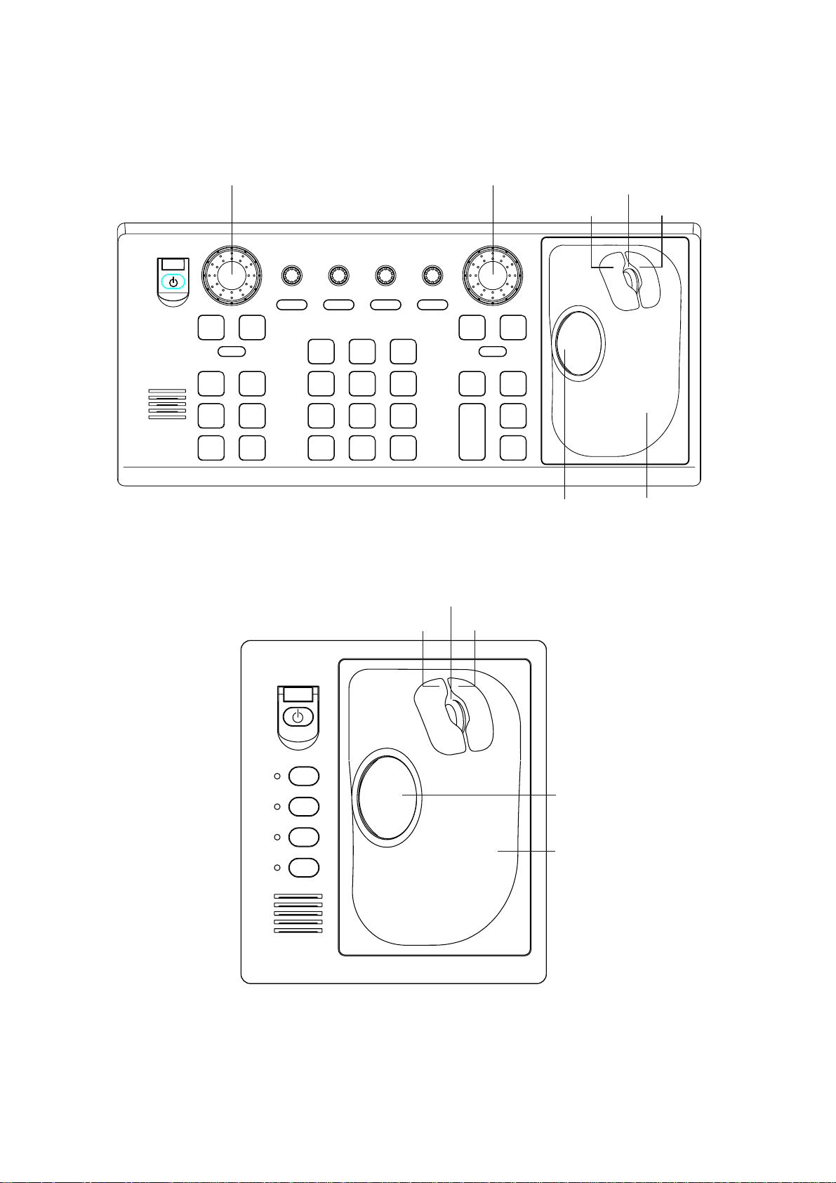
1.3 Control Unit
Two types of c ontrol units ar e avai lable: Control Unit RCU-014 ( full keyboard)
and Control Unit RCU-105 (palm control).
1. RADAR OPERATION
EBL rotary control VRM rotary control
21
EBL
OFFSET
CU/TM
RESET
VECTOR
MODE
0
BRILL
A/C SEAA/C RAIN
3
MODE
6
INDEX
LINE
9
TARGET
LIST
ENTER
MARK
GAIN
OFF
EBL
F1
F3 F4
ALARM
ACK
ON
F2
STBY
TX
BRILL
HL
OFF
45
OFF
CENTER
78
VECTOR
TIME
CANCEL
TRAILS
Control Uni t RCU-014 (ful l k ey board)
OFF
MENU
+
RANGE
-
Wheel
Left button Right button
ON
VRM
ACQ
TARGET
DATA
TARGET
CANCEL
Trackball
Trackball
Module
F1
F2
F3
F4
Wheel
Left button Right button
Trackball
Trackball
Module
Control Uni t RCU-015 (palm control)
1-3
Page 30

1. RADAR OPERATION
Control descr iption
Control Description
Control Unit RCU-014 (full keyboard)
POWE R Turns the system on and off.
EBL an d VRM rotary contr ol s Adjust EBL and VRM, respectivel y.
EBL ON, EBL OFF Tur ns the EBLs on and of f, res pecti v el y.
F1-F4 Execute menu short cut assigned.
ALARM AC K Silenc es audible alarm.
STBY T X Tog gles be tw e en stand-by and tr ans m it.
BRILL Adjusts display brilliance.
A/C RAIN Suppresses rain clutter.
A/C SEA Suppresses sea clutter.
GAIN Adjusts sensitivity of the radar receiver.
HL OFF Temporarily erases the heading line while pressed.
EBL OFFSET Enables, disables the EBL offset. In menu operation, switches
polarity from N or th to So uth and East to We s t an d v i ce versa.
MODE Chooses presentation mode.
OFF CENTER Shifts own ship position.
CU/TM RESET • Moves own ship position in 75% radius in stern direction.
• Resets the heading line to 0° in course-up and true motion
modes.
INDEX LINE Turns index lines on and off.
VECTOR T I ME Chooses vector time (l en gt h) .
VECTOR MODE Chooses vector mode, relative or true.
TARGET LIST Displays ARP target list.
CANCEL TRAILS Cancels all target trails. In menu operation it clears line of data.
ENTER MARK Enters ma rk s ; terminates keyboard input.
VRM ON, VRM OFF Turns the VRMs on and off, respectively
MENU Opens and closes the MAIN menu; closes other menus.
ACQ
RANGE Chooses radar range.
TARGET DATA Displays target data for ARP or AIS target chosen with the
TARGET CANCEL Cancels tracking on ARP, AIS or reference target chosen with
Control Unit RCU-015 (palm control)
POWE R Turns the system on and off.
F1-F4 Execute menu short cut assigned.
• Acquires a target for ARP after choosing it with the trackball.
• Changes a sleeping AIS target to an activated one after
choosing it with the trackball.
trackball.
the trackball.
1-4
Page 31

1.4 Main Menu
You may ac c es s t he MAIN menu from the full keyboard or by using the tr ac k ball.
In later s ections only t he pr oc edur e for menu operation by tr ac kball is given.
Main menu operation by keyboard
1. Press the [MENU] key. The MAIN menu appears in the text area at the right
side of the s cr een.
[MAIN MENU]
1 [ECHO]
2 [MARK]
3 [ALARM]
4 [ARP
5 [PLOTTER]
6 [CARD]
7 [NAV DATA]
8 [NAV LINE
9 [CUSTOMIZE
l
AIS]
z
WPT]
z
TEST]
1. RADAR OPERATION
Echo processing functions
Mainly turns markers on/off.
Sets guard alarm functions; outputs alarm signal.
Sets ARP
Chart and track functions
Memory card functions
Turns nav data on/off.
Processes nav lines and waypoints.
Customizes operation; executes diagnostics.
and AIS functions.
2. Press the numeral key corresponding to the menu you wish to open. For
example, press the [2] key to open MARK menu .
[MARK]
1 BACK
2 OWN SHIP MARK
OFF/ON
3 STERN MARK
OFF/ON
4 INDEX LINE BEARING*
1
REL/TRUE
2
5 INDEX LINE*
1/2/3/6
6 INDEX LINE MODE*
3
VERTICAL/HORIZONTAL
7 [BARGE MARK]
8 EBL OFFSET BASE
STAB GND/STAB HDG/
STAB NORTH
9 [EBL, VRM, CURSOR SET]*
0 RING
OFF/ON
3. Press the numeral key corresponding to the
item you wish to set.
4. Consecutively pres s the same numeral k ey
pressed at s t ep 3 to choose appropr iate
option and then press the [ENTER MARK]
key to register your sel ec tion.
5. Press the [MENU] key to close the menu.
MAIN menu
*1W-type shows INDEX LINE1. Same choices as INDEX LINE.
2
*
W-type shows INDEX LINE2. Same choices as INDEX LINE.
3
*
Shown when INDEX LINE is set to other than "1" .
Not shown on IMO or A type.
4
*
IMO and A types show
9 EBL CURSOR BEARING (REL/TRUE)
4
MARK menu
Useful keys in menu operation
z
To clear a line of numeric data:
Use the [CANCEL TRAILS] key.
z
Switch between plus and minus,
North and South or East and West:
Use the [2] key.
1-5
Page 32

1. RADAR OPERATION
Main menu op erat ion by trackball
1. Roll the trackball to choose the MENU box at the right side of the scr een. The
guidance box at the bottom ri ght corner (see t he illust r ation at the bottom of
the next page for locati on) now reads “DISP MAI N M E NU.”
2. Push the left button to display the MAIN menu.
[MAIN MENU]
1 [ECHO]
2 [MARK]
3 [ALARM]
4 [ARP
5 [PLOTTER]
6 [CARD]
7 [NAV DATA]
8 [NAV LINE
9 [CUSTOMIZE
l
AIS]
z
WPT]
3. Roll the wheel to c hoos e the menu you wish to open and then push the
wheel or the left button. For example, choos e the 2 [MA RK ] menu and then
push the w heel or the left button.
[MARK]
1 BACK
2 OWN SHIP MARK
OFF/ON
3 STERN MARK
OFF/ON
4 INDEX LINE BEARING*
REL/TRUE
2
5 INDEX LINE*
1/2/3/6
6 INDEX LINE MODE*
VERTICAL/HORIZONTAL
7 [BARGE MARK]
8 EBL OFFSET BASE
STAB GND/STAB HDG/
STAB NORTH
9 [EBL, VRM, CURSOR SET]*
0 RING
OFF/ON
1
3
MENU
Menu box
Echo processing functions
Mainly turns markers on/off.
Sets guard alarm functions; outputs alarm signal.
Sets ARP
Chart and track functions
Memory card functions
Turns nav data on/off.
z
TEST]
Processes nav lines and waypoints.
Customizes operation; executes diagnostics.
MAIN menu
*1W-type shows INDEX LINE1. Same choices as INDEX LINE.
2
*
W-type shows INDEX LINE2. Same choices as INDEX LINE.
3
*
Shown when INDEX LINE is set to other than "1" .
Not shown on IMO or A type.
4
*
IMO and A types show
9 EBL CURSOR BEARING (REL/TRUE)
4
and AIS functions.
1-6
MARK menu
4. Roll the wheel to c hoos e item desired and then push the wheel or the l eft
button.
5. Roll the wheel to c hoos e option desired and then push the wheel or the left
button to register your selection.
6. Push the right button to c lose the menu. (Several pus hes m ay be necessary
depending o n the menu used.)
Page 33

1. RADAR OPERATION
1.5 Operation Using the On-Screen Boxes
All radar func t ions can be access ed by using the trackball alone. T his is done by
choosing the appropriat e on- sc reen box with the trackbal l and operating the
trackball module to choose item and option. (See paragraph 1.9 for loc ation of all
on-screen boxes.) On-scr een boxes come in two varieties: Function selection
and function s election w/pop-up menu. On- s c r een boxes of t he latter type have
“►” at the right s ide of their boxes , as in the MARK box shown below.
To operate the radar using on-s creen boxes, do the following:
1. Roll the trackball to place the trac kball marker inside the box desired.
Note: T he trackball marker c hanges it s c onfiguration according to its location.
It is an arrow when placed out s ide the eff ec tive display and a cursor
(+) when i ns ide the eff ective display. See the illustration on the next
page for fur ther details.
For example, c hoose the MARK box , which is at the bottom left corner.
MARK
Mark type last
selected, mark
number
Bearing and range from
own ship to mark
162.5
1
-> +
°
T 11.7 NM
MARK box
When a box is corr ec tly selected, its color changes from green to yellow
(default c olors) and the guidance box at the bottom right c or ner shows
operati onal guidance. The operational guidance shows the func tion of the
left and right buttons, with a diagonal line separat ing the inform ation. For t he
MARK box, for example, the oper ational guidance is “MARK S E LE CT /
MARK MENU.” In this c ase y ou would push the l eft button to choos e a m ar k
or push the right button to open the MARK menu.
Function of left button
Function of right button
MARK Box
MARK
1
> +
Arrow
For choosing
on-screen box
MARK
SELECT
MARK
/
MENU
Guidance box
Guidance box (Exam ple: guidance for MARK box)
1-7
Page 34

1. RADAR OPERATION
Trackball marker location and guidance box indication
The trackball marker is either a cursor (+) or an arrow ( ) depending
on whether it is within or outside the display area, respectively.
Further, the indication in the guidance box changes according to
trackball marker location.
Trackball marker is out of
effective display area
(incl. text area) and
not selecting a box:
The trackball marker is
an arrow
Guidance box reads
"JUMP CURSOR / DISP MENU."
Push the left button to choose the on-screen
box closest to the arrow or push the right
button to display the MAIN menu.
To choose boxes successively, push the wheel
when the guidance box reads as above.
Then, the nearest box is selected and marked
with the double-ended arrow ( ) and the
guidance box reads
"JUMP FORWARD / JUMP BACKWARD."
Hit the left button to go to the box below or
adjacent to the currently selected box or hit
the right button to go to the box above or
adjacent to the currently selected box.
Continue pushing a button to choose boxes
successively. This is convenient for operation
under heavy pitching and rolling. To cancel this
feature, push the wheel when the guidance box
reads as above.
Guidance box reads
"TARGET DATA & ACQ / CURSOR MENU."
In this condition you may access cursor-operated
+
Trackball marker is within
effective display area:
The trackball marker is
a cursor
functions, by hitting the left button for direct
selection of function or the right button to choose
desired functions from the CURSOR menu. For
further details about the CURSOR menu,
see paragraph 1.6.
2. Push the left button (or roll the wheel depending on the box) until the desired
option is displayed in t he box .
Note: When you chose a n on- s c reen box’s option by rolling the wheel, the
box and its contents turn red. This simply i ndicates that the chos en
setting is different from the currently acti ve setting. To change the
setting, push the wheel or the left button. If neither the wheel nor the
left but ton is pushed within about 30 seconds aft er oper ating the wheel,
the previous s et ting is autom atically restored.
1-8
Page 35

1. RADAR OPERATION
3. The pop-up menu attached to the MA RK box is the MA RK menu. To open the
menu, push t he r ight button. The menu open s in the text area at the right si de
of the screen.
[MARK MENU]
1 ORIGIN MARK STAB
GND/SEA
2 MARK KIND
ORIGIN MARK(No. )/
ORIGIN MARK(SYM)/
MAP MARK/
WP 1~50/
WP 51~ 100/
WP 101~150/
WP 151~ 200/
OWN SHIP SHAPE
8 MARK POSN
CURSOR/OS/L/L
00°000.00 N
000°000.00 E
9 MAP DISPLAY
OFF/ON
0 MAP MARK COLOR*
RED/GRN/BLU/YEL/
CYA/MAG/WHT
* Not available on IMO
or A type
MARK menu
Note: Any menu may be operated from the full keyboard or the tr ack ball, or a
combination of the two in case of Control Unit RCU-014. Note that in
later sections only the procedure for menu operation by the
trackball is given.
4. Roll the wheel to c hoos e item desired and then push the wheel or the l eft
button. Selected item is initially s hown in reverse video and c hanges to
normal vide o and circumscr ibed when the wheel or the l eft button is pus hed.
5. Roll the wheel to c hoos e option desired and then push the wheel or the left
button. Selected option is initially shown in reverse vi deo and changes to
normal vide o and circumscr ibed when the wheel or the l eft button is pus hed.
6. Push the right button to c lose the menu. (O n some menus sever al presses of
the right button are requi red to close the menu. )
1-9
Page 36

1. RADAR OPERATION
1.6 Cursor Menu
Functions which require the use of the cursor, s uc h
as EBL offset and zoom , may be activated directly
from the gui dance box or from the CURSOR menu,
either met hod with the curs or inside the effective
display area. Below is the procedure for choos ing a
cursor-related f unct ion from the CURSOR menu. In
later sect ions only the proc edure for selec tion from
the guidanc e box is given.
1. Roll the trackball to place the cursor inside the
effective display area.
2. Roll the wheel t o s how “TARGET DATA & ACQ /
CURSOR MENU” in the guidanc e box .
3. Push the right button to s how the CURSOR
menu.
4. Roll the wheel to c hoos e “ 2” and then push the
wheel or the left button.
5. Roll the wheel to c hoos e function desi r ed and then push the wheel or t he left
button.
[CURSOR MENU]
↓
2
TARGET DATA & ACQ/
TARGET CANCEL/
ARP TGT DATA & ACQ/
TARGET TRACK ON*/
TARGET TRACK OFF*/
REF MARK/
EBL OFFSET/
OFFCENTER/
ZOOM/
MARK DELETE/
CHART ALIGN/
↑
8
*
Not available on IMO type
Note: For operation from the keyboard, you may press t he [ 2] key to choose a
function in top-to-bott om or der or the [8] key t o choose in reverse order.
Cursor Menu item Description
TARGET DATA & ACQ
ARP: Acquires ARP t ar ge t; dis plays data for ch os e n ARP t ar ge t.
AIS: Activates sleeping AIS target; display data for chosen AIS
target.
TARGET CANCEL
ARP: Cancels tracking on chosen ARP target.
AIS: Sleeps chosen AIS target.
ARP TGT DATA & ACQ Acquires chosen echo as ARP target.
TARGET TRACK ON Turns ARP target track on. (A, B, C and W types)
TARGET TRACK OFF Turns ARP target track off. (A, B, C and W types)
REF MARK Inscribes reference mark, for target-based speed input.
EBL OFFSET Offsets EBL to measure range and bearing between two targets.
OFF CENTER Shifts screen center to chosen location.
ZOOM Zooms chosen location.
MARK DELETE
Deletes chosen mark (plotter mark, origin mark or waypoint
mark).
CHART ALIGN Aligns chart with radar picture.
1-10
Page 37

6. The guidance box shows “XX / EXIT.” (XX = function chos en) . Roll the
trackball to place the cur s or where desired.
7. Push the left button to execute the f unc tion select ed at step 5.
8. To quit the func tion select ed, push the right but ton when the guidance box
shows “XX / EXIT.” (XX = function chosen at s tep 5)
1.7 Monitor Brilliance
The bril liance of the entire screen shoul d be adjusted accor ding to lighting
conditi ons . Monitor brilliance should be adjusted befor e adjusting rel ative
brilliance levels on the BRILL m enu t o be explained later.
Note: The brilli anc e of a commercial m onitor cannot be a djusted from t he r adar.
See the ow ner’s manual of the comm er c ial monit or f or how to adjust its
brilliance.
By keyboard
1. RADAR OPERATION
Operate the [ B RILL] control on the control unit to adjust brilliance. Turn it
clockw ise to increase bri lliance; count erc lockwise to dec r ease brilliance. Wat c h
the BRILL box (see i llustration below) to know current brilliance level.
By trackball
1. Roll the trackball to place the arrow on the brilliance l ev el indicator in the
brilliance level indi c ation box at the bot tom left corner of the screen.
Brilliance bar
Shows brilliance level.
Place arrow inside box
to adjust screen brilliance.
BRILL1
Brillance, color set no.
(For details, see para. 1.50.)
26
Brilliance level
Brillianc e level indicator
2. Roll the wheel downward to increase bri lliance or r oll it upward to decr ease
brilliance. The length of the brilliance bar increases or decreases with
operati on of the wheel.
Note: If nothing appears on the sc r een at power - up when using Cont r ol Unit
RCU-015 (palm control) or when the radar is in stand-by, press and hold
down any key except the power switch for four seconds to automatically
set up for medi um display br illiance.
1-1 1
Page 38

1. RADAR OPERATION
1.8 Choosing the Display Mode
This radar has two displ ay m odes : Radar and Radar + P lotter. Choose a di s play
mode as below. Note that a display m ode c annot be chosen when the menu is
open.
1. Roll the trackball to place the arrow in the DISPLAY MODE box at the top of
the screen.
DISPLAY
XX*
* XX = display mode
(RADAR, +PLOTTER)
DISPLAY MODE box
2. Push the l eft button to choose appropriate mode:
RADAR: Radar picture
+PLOTTER: Radar picture + plotter picture (incl. chart)
1-12
Page 39

1.9 On-Screen Boxes and Markers
Reference Point Box
Trial Maneuver (Elapsed time shown
when trial maneuver is active.)
PICTURE Box, Main Picture Settings
PULSELENGTH Box
ANTENNA Box
PRESENTATION MODE Box
RANGE Box
DISPLAY MODE Box
Heading Marker
6
HEAD UP TB RM
ANT 1 X-BAND
PULSE S1
PICTURE4
IR OFF
ES OFF
EAV OFF
AUTO RAIN
OFF
NM/1DISPLAY
RADAR
320
310
300
Index
330
340
Heading
Line
350
000
Line
290
No. 2
EBL
Guard
Zone
Cursor
OS
Symbol
280
270
260
No. 1
EBL
250
No. 1
220
WATCH
11 : 28
VRM
210
200
Stern
Marker
190
Origin Mark
180
IL1
ON
032. 0°T
5. 60NM
MARK
190.0°T, 5.75NM
BRILL1
HL
EBL1
OFF
TX
EBL2
STBY
240
230
+
26
>280.9°T<
240. 8°R
WATCH Box
EBL2 Box
EBL1 Box
(Alarm watch
time)
TX/STBY Box
HL OFF Box
BRILL Box
MARK Box
Bearing and range to mark
IL (Index Line) Box
Index line orientation,
Index line interval
010
North
Marker
170
SET and DRIFT Boxes
CURSOR DATA Box
GAIN Setting
A/C SEA Setting
A/C RAIN Setting
TUNING Setting
040
140
VRM1
VRM2
GAIN
SEA AUTO
RAIN
TUNE AUTO
050
130
>3.682NM<
020
160
REF POINT
ANT POSN
030
No. 2
VRM
150
CU/TM
RESET,
ALARM ACK
Box
VRM2 Box
VRM1 Box
TRAIL MODE Box
ALARM Box
Guard Zone (GZ) Box
Display screen
25
22
19
34°40. 649 N
+
135°18. 303 E
000. 0°TSET
0. 9ktDRIFT
TRIAL OFF
MENU
CHART
ALIGN
060
070
Range
Rings
080
090
100
110
120
TARGET
LIST
GZ1
GZ2
ALARM1
ALARM2
TRUE TRAIL OFF
5.221NM
CU/TM
RESET
ALARM
ACK
ARP VECTOR Box
PAST POSN Box
1. RADAR OPERATION
Note: Speed, Set and
Drift values not shown.
HDG
000.0°T
SPD
0.0kt BT
SB
COG
SOG
OS POSN
DGPS
0.0kt
00.0°T
0.0kt
34°40.00N
135°24.00E
ZOOM or ARP
DATA BOX
(See next page.)
ZOOM, ARP,
or AIS DATA BOX
(See next page.)
ARP,
AIS DATA BOX
DISP
OFF
ARPA
AIS
OFF
MANU
VECTOR TRUE
PAST POSN REL 3M
CPA LIMIT 0. 5NM 22MIN
ALERT BOX
(See next page.)
TARGET
DATA & ACQ
CURSOR
MENU
Guidance
Box
CPA LIMIT Box
Heading
WT
Speed, Source
MAN
Log Speed
Course over Ground
GPS
Speed over Ground,
Source
Position
MENU Box
Chart Align ON
TARGET LIST
Box
ARP ACQ
MODE Box*
AIS DISP Box
AIS Message Arrival
30M
*: "ATA" replaces
"ARPA" when
ATA function is
used.
1-13
Page 40

1. RADAR OPERATION
Electronic Position-fixing
System and position*
Depth
Depth
Echogram
(See 1.40.)
Zoom display appears
in nav data box when
nav data is turned off.
ARP Target
Data (or
Zoom)
HDG
SPD
SB
COG
SOG
OS POSN
DGPS
242.2°T
9.9kt BT
0.1kt
30.2°T
10.2.2kt
34°40.00N
135°24.00E
WT
MAN
GPS
DEPTH 22.30 m WIND 15.4 m/s
20
40
60
80
-30 20 10
CURRENT 2.3kt 69.9
TEMP 16°C TTG 00:00:00
WPT001 6.5NM 35.2°R
DATE OCT/25/03 10:00 UTC
100
45.1°T
N
WE
S
°R
Heading is TRUE
(variation-corrected gyro or
magnetic heading)
Speed data is LOG, MAN, etc.,
showing sensor and types.
CSE when water tracking mode is
selected.
STW when water tracking
mode is selected.
Wind Speed and Angle
(True or Relative angle)
Tide relative to North,
full scale 10 kt
Wind direction relative to
own ship heading, full
scale 100 kt.
Current speed and direction
Water temperature, TTG*,
WPT no., range and bearing
to waypoint
Date, time
* TTG shown as "00:00" when
there is no cursor data.
ARP Target
Data
(See Chapter 3.)
* GPS, DGPS,
PPS, RTK, FRTK,
DR. PPS, RTK
and FRTK require
GGA sentence.
ARP TARGET
No. 42
BRG 25.5°T
RNG 3.4NM
T CSE 264.0°T
T SPD 12.3KT
CPA 2.9NM
TCPA 12.2MIN
BCR 1.7NM
BCT 20MIN
ARP, AIS Functions Box
GUARD ALARM, TIMER ALARM, GUARD ZONE,
LOST TRGT, CPA/TCPA, TARGET FULL(AUTO),
TARGET FULL(MAN), AZIMUTH, HEAD LINE,
TRIGGER, VIDEO, GYRO, LOG, EPFS, XTE,
ARRIVAL WPT, DEPTH,RECEIVE, other
Guidance Box
Data fields
Alert Box
(Warnings and Alert
Messages)
1-14
Page 41

1.10 Tuning the Receiver
1.10.1 Choosing the tuning method
The tuning method can be selected with the TUNE box at the top of the scree n.
1. Roll the trackball to choose the TUNE box (TUNE AUTO or TUNE MAN) at
the top of the s cr een.
Tuning method (AUTO or MANU)
TUNE AUTO
1. RADAR OPERATION
Tuning bar
Place arrow inside box
to adjust tuning, when
TUNE MANU is selected.
2. Push the l eft butt on or r oll the wheel to display TUNE AUTO or TUNE MAN
as appropri ate.
3. If you used the wheel to choose tuning met hod, push the wheel or the l eft
button to change setting.
1.10.2 Initializing tuning
Automati c t uning is initi alized during the installation. However, if you feel that
automatic t uning is not w or k ing properly try r e- initializi ng it as follows:
1. Roll the trackball to choos e the MENU box at t he right side of the screen and
then push the wheel or t he left button.
2. Roll the wheel to choos e 1 E CHO and then push t he wheel or the left button.
[ECHO]
1 BACK
ND
2 2
ECHO REJ
OFF/ON
3 TUNE INITIALIZE
4 PM*
5 SART
OFF/ON
6 WIPER
OFF/1/2
7 ECHO AREA*
1
OFF/ON
2
CIRCLE/WIDE/ALL
Tuning level
TUNE box
1
*
Not available on FAR-2157/2167DS
2
*
Not available on IMO or A type
ECHO menu
3. Roll the wheel to choos e 3 TUNE INIT I A LIZE.
4. Push the wheel or the left button t o initialize automatic tuning. (For operati on
from the keyboard, press t he [ENTER MA RK] key.) “WORK IN PROGRESS
– TUNE INITIALIZE appear s in the Alert Box dur ing the initialization.
5. Push the right button twice to close the menu.
1-15
Page 42

1. RADAR OPERATION
1.10.3 Automatic tuning
Choose automatic tuning following paragraph 1. 10.1. T he TUNE box shows
TUNE AUT O.
1.10.4 Manual tuning
1. Roll the trackball to choos e the RANGE box at top left c or ner and t hen push
the left or right button as appr opriate to c hoos e the 48-mile range. Push t he
left but ton to lower the range; the right button to raise the range.
2. Choose manual tuning f ollowing the pr ocedure in par agraph 1.10.1.
3. Roll the trackball to place the arrow on the tuning bar area in the TUNE box .
4. Roll the wheel to adjust tuning. The best tuning point is wher e the bar graph
swings m ax imum. The ar r ow below the bar graph shows t uning control
positi on; not the tuning condition.
1.11 Aligning Heading with Gyrocompass
With connection of a gyrocompass, ship' s heading is displayed at the r ight side
of the screen. Upon turning on the radar, ali gn the on-screen GYRO readout with
the gyrocom pass readi ng by following the procedure sh own below. O nc e you
have set the i nitial heading c orr ec tly, resetting is not usual ly required. However, if
the GYRO readout looks wrong or the gyro alarm sounds, follow the proc edur e
below. Note that the FURUNO SC- 60/120 does not require alignment on the
radar.
1. Roll the trackball to place the arrow in the HDG box at the top right corner of
the screen.
2. Push the right button to open the HDG menu.
3. Roll the wheel downward to choose GC-10 SE TTI NG and t hen push the
wheel or the left button.
[HDG MENU]
1 HDG SOURCE
AD-10/SERIAL
2 GC-10 SETTING
000.0°
HDG menu
1-16
Note: I f heading source sel ec t ed is not suitable change it at 1 HDG
SOURCE to mat c h your heading s ource.
4. Roll the wheel to set t he heading. (For entry through the keyboard use the
numeric keys.)
5. Push the wheel to finish.
6. Push the right button to close the menu.
Page 43

1.12 Presentation Modes
This radar has the following present ation modes:
Relative Motion (RM)
Head-up: Unstabilized
Head-up TB: Head-up with compass-stabilized bearing scale (True Bearing)
where t he bear ing scale rotates with t he c om pass reading.
Course-up: Compass-stabilized relative to ship’s orientation at the time of
selecting course-up.
North-up: Compass-stabilized with reference to north
St er n- up: The radar image is rotat ed 180°. Graphics and relati ve and tr ue
bearings ar e also rotat ed 180°.
True Motion (TM)
North-up: Ground or sea s tabilized with co m pass and speed i nputs.
Stern-up: Same as in relative motion.
1.12.1 Choosing presentation mode
1. RADAR OPERATION
By keyboard
Press the [MODE] key cons ec utively t o c hoose pr es entation mode desired. The
PRESENTATION MODE box shows the current presentation mode. (See the
illust ration below.)
By trackball
1. Roll the trackball to place the arrow in the PRESENTATION MODE box at
the top left corner of t he s c r een.
HEAD UP RM*
* = Other modes:
STERN-UP, HEAD UP TB RM, COURSE UP RM,
NORTH UP RM, NORTH UP TM
PRESENTATION MODE box
2. Push the l eft button to choose mode desir ed.
Loss of g yro compass signal
When the compass signal is lost, “HE A DING SET” appears in red at the gyro
readout, the present ation mode autom atically becomes head-up, all ARP and
AIS t ar gets and map or chart ar e erased. After restoring the compass signal,
choose the presentation mode with the [MODE] key or the PRESENTATION
MODE box.
1-17
Page 44

1. RADAR OPERATION
1.12.2 Description of pr e se ntatio n mo de s
Head-up mode
The head-up mode is a display in which the line connecting own shi p and the top
of the display indicat es own ship’s heading.
The target pips are painted at their measured distances and i n their directions
relati ve to own ship’s heading.
A short line on the bear ing scale is the north marker indicati ng heading sensor
north. A failure of the heading sens or input will cause t he north marker to
disappear and the readout to show ***.*° and the message HDG S IG MISSING
appears in red at the lower-right corner of the screen.
North Marker
Heading Line
Note: When display is off-centered,
the heading mark appears at 000 degrees.
Head-up mode
Course-up mode
The course- up mode is an azim uth stabilized display in which a line c onnec t ing
the center w ith the top of t he display indic ates own ship’s intended course
(namely, own ship’s previous h eading just before this mode has been selected).
Target pips are painted at their m eas ured distances and in their di r ec tions
relati ve to t he intended course, whic h is m aintained at the 0-degree posit ion. The
heading l ine moves in accor dance wit h ship’s yawing and c our s e c hange. This
mode is useful to avoid smearing of pictur e dur ing course change.
1-18
North Marker
Heading Line
Course-up mode
Page 45

1. RADAR OPERATION
Head-up TB (True Bearing) mode
Radar echoes ar e s hown i n the same way as in the head-up m ode. The
difference from normal head-up prese ntation lies in the ori entation of the bear ing
scale. The bearing scal e is heading sens or s tabilized. That is, it rotates in
accordance with the headi ng sensor signal , enabling you to know own ship’s
heading at a glance.
This mode is available w hen the radar is interfaced wi th a gyro heading sens or.
If the gyro heading sensor fails, the bearing scale retur ns t o the state of head-up
mode.
North-up mode
The north- up m ode paints target pips at their meas ur ed dist anc es and in their
true (heading sensor) di rec tions from own ship, north bear ing maint ained at the
top of the screen. The heading line changes its direc tion according to the ship’s
heading. Requires heading s ignal.
If the compass fail s, the presentation mode changes to head-up and t he nor th
marker disappears. Also, the HDG indicat ion shows ***.*°. A nd the message
HDG SIG MISSI NG appears in red at the lower-right corner of the screen.
North Marker
North-up mode
Stern-up mode
The ster n- up mode r otates the
head-up mode picture, relative and
true bearings and display graphics
180°. This mode is usef ul on
dual-radar tugboats when backing up;
one radar shows head-up an d another
shows s tern-up. To enable the
stern-up mo de, turn on STE RN- UP on
the 7 OPERATION menu. St er n- up is
not avail able on the IMO or A type.
Heading Line
North Marker
Heading Line
St er n- up mode
1-19
Page 46

1. RADAR OPERATION
True motion mode
Own shi p and other moving objec ts move in accordance w ith their true c our s es
and speed. In ground stabilized TM, all fixed targets, such as landmasses,
appear as stationary echoes. In the sea stabilized TM wit hout set and drift inputs,
the landmass can move on the s cr een. Note tha t true motion is not available on
the 72 nm (non-IMO type only) or 96 nm range sc ale. If COG and SOG (both
over the ground) are not available on TM mode, enter the s et (tide dir ec tion) and
drif t (tide speed) manually referring to the Tide Table.
When own s hip reaches a point cor r esponding t o 50% of the radius of the
display, own ship position is automatical ly r eset to a point of 75% radi us opposite
to the extension of the heading line pas s ing through the display center. You may
also reset t he own ship sy m bol manually by pr es s ing the [CU/TM RESET] key,
or roll the t rackball to choose the CU/TM RESET box at the bottom right corner
of the display and then push t he left but t on.
If the headi ng s ensor fail s , t he m ode is changed to the head-up and the north
marker disappears. The HDG readout shows ***.*° and the message HDG SIG
MISSING appears in red at the lower-ri ght corner of the screen.
North Marker
Heading Line
Heading
line
300
290
280
270
260
250
240
True motion mode
Automatic resetting of own ship mark in true motion mode
North
000 010
350
340
330
320
310
230
220
210
200
(a) True motion
is selected
marker
020
030
040
050
060
070
080
090
100
110
120
130
140
150
160
170180190
320
310
300
290
280
270
260
250
240
230
220
000 010
350
340
330
210
200
020
030
040
050
060
070
080
090
100
110
120
130
140
150
160
170180190
(b) Own ship has reached a
point 75% of display radius
000 010
350
340
330
320
310
300
290
280
270
260
250
240
230
220
210
200
(c) Own ship is automatically
reset to 75% of radius
020
030
040
050
060
070
080
090
100
110
120
130
140
150
160
170180190
1-20
Page 47

1. RADAR OPERATION
1.13 Entering Own Ship's Speed
The ARP and azimuth st abilized presentation modes require own ship speed
input and compass signal. The speed c an be entered fr om a log (STW) or GPS
(SOG) or manually on the menu. Note that FURUNO GPS Navigat or GP-90
provides COG and SOG.
1.13.1 Automatic speed input by log or GPS navigator
1. Roll the trackball to place the arrow in the SPD box at the top right corner of
the screen.
2. Push the right button to display the SPEED menu.
3. Roll the wheel to choose 1 SHIP SPEED and then push the w heel or the left
button.
4. Roll the wheel to choos e t he appr opriate sourc e for automatic speed input
and then push the wheel or t he left button.
LOG (BT) : Log, spe ed over ground (S O G). Note that a log cannot produce
BT (Bottom Tracking) speed in deep waters without set and drift
entry.
LOG (WT): Log, speed thru water (STW)
GPS: Speed i nput by GPS navigator
5. Push the right button to close the menu.
Notes on speed input
[SPEED MENU]
1 SHIP SPEED
LOG(BT)/LOG(WT)/
GPS/MANUAL/REF
2 MANUAL SPEED
0.0kt
3 SET DRIFT
OFF/ON
SPEED menu
• IMO Resol ut ion A.823(19) for ARPA recommend s that a speed log to be
interfac ed with an ARPA should be capable of pr ovi ding through - t he- water
speed (forward speed).
• Be sure not to choose a LOG opti on when a speed log is not connected. If the
log signal is not provided, t he s hip speed readout at the top of the screen will
be blank. In the event of a log error, enter speed manually.
• Warni ng label SPD **.* and LOG appear if no log signal is present f or 30 s
whil e the ship’s speed has been more than 5 kt.
• With the serial speed inputs and SOG selection, if the type of data is changed
from SOG t o STW the label SOG appear s in red (at t he upper r ight corner of
the displ ay).
• When the AIS feat ur e is active, MANUAL and REF are shown in gray to
indicat e they are not avail able for selection.
1-21
Page 48

1. RADAR OPERATION
1.13.2 Manual speed input
If the speed log is not work ing, enter speed manually as below. In this case the
speed data type is shown as MANUAL and is speed thru water (STW). Note that,
for the IMO s pec ification r adar, m anual speed input is not available when the AIS
feature is active.
1. Roll the trackball to place the arrow in the SPD box at the t op r ight corner of
the screen.
2. Push the right button to display the SPEED menu.
3. Roll the wheel to choos e 1 SHIP SPEED and then push the wheel or the lef t
button.
4. Roll the wheel to c hoos e MANUAL and then push the wheel or the left button.
5. Roll the wheel to choose 2 MANUAL SPEED and then push the wheel or the
left but ton.
6. Roll the wheel to set speed. ( For entry t hr ough the keyboard, use t he
numeric keys.)
7. Push the wheel to finish.
8. Push the right button to c lose the menu.
1.14 Choosing the Range Scale
The sel ec ted range scale, range ring inter val and pulselengt h are shown at the
upper left corner on the s cr een. When a t ar get of interest comes closer, r educ e
the range scale so that it appear s in 50-90% of the display r adius.
By keyboard
Use the [RANGE] key to choose r ange desired. Hit the “+” part of the key to
raise the range; the “-“ part to lower t he range.
By trackball
1. Roll the trackball to choos e the RANGE box at the top lef t corner of the
screen. The guidance b ox s hows “RANG E DOWN / RANGE UP.”
2. Push the l eft button to lower the range; t he r ight button to r aise the range.
You may also choose the rang e by rolling the wheel and then pushing it or
the left button.
NM
0.125
0.025
RANGE box
1-22
Page 49

1.15 Choosing the Pulselength
The puls elength in use i s displayed at the upper - left position of the screen usi ng
the indic ations shown in the tabl e below .
1. RADAR OPERATION
Label and pulselength
Indication Pulselength (μs)
S1 (Short pul s e 1) 0.07
S2 (Short pul s e 2) 0.15
M1 (Medi um pulse 1) 0.3
M2 (Medi um pulse 2) 0.5
M3 (Medi um pulse 3) 0.7
L (Long pulse) 1.2
*: S, M1, M 2 and L on FAR-2157( - B B ) and S -band radar s .
Appropri ate pulselengths are preset to i ndividual range s c ales and functi on k eys.
If you are not satisfied with the current pul selength settings, you may change
them as shown below.
1.15.1 Choosing pulselength
You can choose the pulselengt h for the 0.5 to 24 nm range scales as bel ow.
1. Roll the trackball to choos e the PICTURE box at the left side of the scr een.
Note: The PICTURE box s ets up the radar picture according to expect ed
usage, such as harbor navig ation, long range, short range, etc. For
further details see paragraph 1.33.
2. Push the right button to show the PICT URE m enu.
[PICTURE MENU]
1 INT REJECT
OFF/1/2/3
2 ECHO STRETCH
OFF/1/2/3
3 ECHO AVERAGE
OFF/1/2/3
4 NOISE REJ
OFF/ON
5 AUTO STC
OFF/ON
6 AUTO RAIN
OFF/1/2/3/4
7 VIDEO CONTRAST
1/2/3/4/
A/B/C
8 [PULSE]
9 [CONDITION]
0 DEFAULT (ENTERX3)
PICTURE menu
1-23
Page 50

1. RADAR OPERATION
3. Roll the wheel to choos e 8 [ P ULS E ] and then push the wheel.
[PULSE MENU]
1 BACK
2 0.5NM
S1/S2
3 0.75NM
S1/S2/M1
4 1.5NM
S1/S2/M1
5 3NM
S2/M1/M2/M3
6 6NM
M1/M2/M3/L
7 12-24NM
M2/M3/L
[PULSE MENU]
1 BACK
2 0.75NM
S/M1
3 1.5NM
S/M1
4 3NM
M1/M2
5 6NM
M2/L
6 12-24NM
M2/L
PULSE menu PULSE menu
(12, 25 kW X-band) (50 kW X-band, all S-band)
4. Roll the wheel to choos e a range and then push the wheel or the left butt on.
5. Roll the wheel to choos e pulselength desi r ed and then pus h the wheel or the
left but ton.
6. Push the right button tw ice to close the menu.
1.15.2 Changing pulselength
1. Roll the trackball to choos e the PULSELENGTH box at the left side of the
screen. The guidance b ox s hows “PULSE NA RROW / PULSE WIDE. ”
PULSE XX*
* XX = Pulse width setting
PULSELENGTH box
2. Push the l eft button to shorten the pulselength or the r ight button to widen the
pulselengt h. You may also choose the pulselength by r olling the wheel and
pushing it or t he left button.
1-24
Page 51

1.16 Adjusting the Sensitivity
The gain c ontrol adjusts the sensitivity of the recei ver.
The proper setting is such that the background noise is just visible on the screen.
If you set up f or too little sensitivity, w eak ec hoes may be missed. On the other
hand excessive sensiti vi ty yields too much bac kground nois e; strong tar gets may
be missed because of the poor contrast between desired ech oes and the
backgroun d noise on the display.
To adjust receiver sensit ivity, adjust the gain control so background noise is just
visible on the screen.
By keyboard
While moni t or ing the gain level indicator at the top of the screen, operate the
[GAIN] control to adjus t t he s ens itivity.
By trackball
1. RADAR OPERATION
1. Roll the trackball to place the arrow on the gain level indicator at the top of
the screen.
Level bar
Place arrow inside
window to adjust gain.
GAIN
2. Roll the wheel dow nward to increase the gain or upward to decrease it. 100
levels (0-100) are available.
30
GAIN level indicator
1-25
Page 52

1. RADAR OPERATION
1.17 Suppressing Sea Clutter
Echoes from waves cover the c entral part of the display with random signals
known as s ea c lutter. The higher the waves, an d the higher the antenna above
the wat er, the furt her the clutter will ext end. When sea clutter masks the picture,
suppress it by the A/C SEA control, either manu ally or automatically.
1.17.1 Choosing metho d of ad ju stme nt
1. Roll the trackball to choos e S E A AUTO or SEA MAN (whichever is shown) at
the top of the display.
Level bar
Place arrow inside window
to adjust A/C SEA.
SEA AUTO
A/C SEA adjustment
method (SEA AUTO or SEA MAN)
A/C SEA level indi c ator
2. Push the left button to display S E A AUT O or S E A MA N as appr opriate.
30
1.17.2 Automatic adjustment by the A/C SEA control
Auto A/C SEA all ows for fine tuning of the A/C SEA circuit , within ±20 dB.
Accordingly, with the bar reading set t o 100, gain is not lowered to mini m um as
with manual A/ C S E A on close-in ranges. Further, the auto A / C S E A level is low
because the average value of the original input echo is l ow in areas where ther e
are no sea surf ace r eflections . For example, when the ship is alongside a quay
and the radar picture shows echoes from both land and sea, y ou c an observe
the size of echoes because the STC curve is di fferent depending size of echoes.
Note: The auto A/C funct ion can erase w eak target echoes. Adj ust the control
carefully, watching the dis play.
By keyboard
1-26
1. Choose SEA AUTO foll owing the procedure in paragraph 1. 17.1.
2. While observing the A/C SEA level indicator, adjust the A/C SEA with the [A/ C
SEA] control. 100 levels are available.
Page 53

By trackball
1. Choose SEA AUTO foll owing the procedure in paragraph 1. 17.1.
2. Roll the trackball to place the arrow in the A/C SEA level indicator at the top
of the display.
3. While observing the A/C SEA level indicator, roll the w heel downward t o
increase the A/ C S E A or upward to decreas e it. 100 levels ( 0-100) are
available.
1.17.3 Manual adjustme nt o f A/C SEA
The A/C SEA contr ol reduces the amplification of echoes at short ranges (where
clutter is the greatest) and progressivel y increases amplific ation as the range
increases, s o am plific ation will be normal at those ranges where there is no sea
clutter.
The proper setting of the A/ C S E A should be such that the c lutter is broken up
into small dots, and small targets become dist inguishable. If the setting is set too
low, targets will be hidden in the clutter, while if the setting is too high, both sea
clutter and targets will disappear from the displa y. In most cases adjust the
control unt il clutter has disappeared to leeward, but a little is stil l vi s ible
windward.
1. RADAR OPERATION
Sea clutter at
screen center
A/C SEA adjusted;
sea clutter suppressed
By keyboard
1. Choose SEA MAN following the procedure in paragraph 1. 17.1.
2. Watching the A/C SE A level indicat or at the top of the display, adjust the A/C
SEA with the [A/C SEA] control. 100 levels (0-100) are available.
By trackball
1. Choose SEA MAN followi ng the procedure in paragraph 1.17. 1.
2. Roll the trackball to place the arrow on the A/C SEA level indicat or at the top
of the display.
3. While observing the A/C SEA level indicator, roll the w heel downward t o
increase the A/ C S E A or upward to decreas e it. 100 levels ( 0-100) are
available.
1-27
Page 54

1. RADAR OPERATION
1.18 Suppressing Rain Clutter
Use the AUTO RAIN and A/C RAIN to suppress rai n c lutter. AUTO RAIN
suppresses rain clutter in the pictur e and A/ C RA IN suppresses clutter pick ed up
by the antenna.
1.18.1 Turning AUTO RAIN on or off
1. Roll the trackball to choos e the PICTURE box at the left side of the scr een.
2. Push the right button to show the PICT URE m enu.
3. Roll the wheel to c hoos e 6 AUTO RAIN and t hen push the wheel .
4. Roll the wheel to c hoos e AUTO RAIN setting desired. The higher the number
the greater the degree of rain clutter suppr es s ion. OF F turns off the AUTO
RAIN feature.
5. Push the right button to close the menu.
[PICTURE MENU]
1 INT REJECT
OFF/1/2/3
2 ECHO STRETCH
OFF/1/2/3
3 ECHO AVERAGE
OFF/1/2/3
4 NOISE REJ
OFF/ON
5 AUTO STC
OFF/ON
6 AUTO RAIN
OFF/1/2/3/4
7 VIDEO CONTRAST
1/2/3/4/
A/B/C
8 [PULSE]
9 [CONDITION]
0 DEFAULT (ENTERX3)
PICTURE menu
1-28
Page 55

1.18.2 Adjusting A/C RAIN
The verti c al beam width of the antenna is designed to see surface targets even
when the s hip is rolling. However , by this desi gn the unit will also detect rain
clutter (r ain, snow, or hail) in the same manner as nor mal targets.
The A/C RAIN control adj us ts the receiver sensitivi ty as the A/C SEA control
does but rat her in a longer tim e per iod (longer r ange). The higher the setting the
greater the a nti-clutter effect. When echoes from pr ec ipitation mask solid targets ,
adjust the A/ C RA IN control to split up these unwanted echoes into a s pec k led
pattern, making recog nition of solid targets easier.
1. RADAR OPERATION
(a) True target trails
(No smearing of
stationary targets)
(b) Relative target trails
Targets moving relative
to own ship
Appearanc e of rain clutter
Keyboard
Adjust t he A/C RAIN with t he [A/C RAIN] control.
Trackball
1. Roll the trackball to place the cursor i n the A /C RAIN level i ndicator at the top
right side of the displ ay.
Level bar
(Shows A/C RAIN level.)
Place arrow inside window
to adjust A/C RAIN.
RAIN
30
A/C RAIN level indicat or
2. While observing the A/C RAIN level indicator, roll t he wheel downw ar d to
increase the A/ C RA IN or upw ar d to decrease it. 100 lev els (0-100) are
available.
1-29
Page 56

1. RADAR OPERATION
1.19 Interference Rejector
Mutual r adar interference may occur in the vi c inity of another shipborne radar
operati ng in the same frequency band. It is seen on the screen as a num ber of
bright spikes either i n ir r egular patter ns or in the form of us ually curved
spoke-li ke dotted lines ex tending from the c enter to the edge of t he picture.
Activating the interfer enc e r ejector cir cuit can reduce this type of interference.
The interference rejector is a kind of signal correl ation circuit . It compares t he
received si gnals over succ es s ive transmi ss ions and suppresses randoml y
occurring signals. There are three levels of inter ference rejection dependi ng on
the number of transmissi ons that are correlat ed.
Interference
1. Roll the trackball to choose the PI CTURE box at the left side of the screen.
2. Push the right button to s how the PICTURE menu.
[PICTURE MENU]
1 INT REJECT
OFF/1/2/3
2 ECHO STRETCH
OFF/1/2/3
3 ECHO AVERAGE
OFF/1/2/3
4 NOISE REJ
OFF/ON
5 AUTO STC
OFF/ON
6 AUTO RAIN
OFF/1/2/3/4
7 VIDEO CONTRAST
1/2/3/4/
A/B/C
8 [PULSE]
9 [CONDITION]
0 DEFAULT (ENTERX3)
PICTURE menu
3. Roll the wheel to c hoos e 1 INT REJECT and then push t he wheel.
4. Roll the wheel to c hoos e r ejection l evel des ired and then push t he wheel or
the left button. “3” provi des the highest degr ee of suppress ion.
5. Push the right button to c lose the menu.
1-30
Page 57

1.20 Measuring the Range
The range to a target may be measured three ways: with the fixed range rings,
with the curs or, or with the VRM.
Use the fix ed range rings to obtain a rough estimate of the range to a target.
They are t he c oncentric solid circles about own ship, or the sweep origin. The
number of rings is automat ically determ ined by the selected range scale and
their i nterval is displayed at the upper-left position of the screen. C ount the
number of rings betw een the center of the di s play and the tar get. Check the
range ring interval and judge the distance of the echo from the inner ed ge of the
nearest ring.
1.20.1 Turning range rings on/off
1. Roll the trackball to choose the MENU box at the right side of the scr een. The
guidance box at the bottom ri ght corner (see t he illust r ation at the bottom of
the next page for locati on) now reads “DISP MAI N M E NU.”
2. Push the left button to display the MAIN menu.
3. Roll the wheel to c hoos e 2 [MARK] and then pu s h the wheel or the left
button.
1. RADAR OPERATION
[MARK]
1 BACK
2 OWN SHIP MARK
OFF/ON
3 STERN MARK
OFF/ON
4 INDEX LINE BEARING*
REL/TRUE
5 INDEX LINE*
1/2/3/6
6 INDEX LINE MODE*
VERTICAL/HORIZONTAL
7 [BARGE MARK]
8 EBL OFFSET BASE
STAB GND/STAB HDG/
STAB NORTH
9 [EBL, VRM, CURSOR SET]*
0 RING
OFF/ON
2
1
3
4. Roll the wheel to c hoos e 0 RING and then push the wheel or the left button.
5. Roll the wheel to c hoos e OFF or ON as appropriate and then push the w heel
or the left button.
6. Push the right button twice to close the menu.
*1W-type shows INDEX LINE1. Same choices as INDEX LINE.
2
*
W-type shows INDEX LINE2. Same choices as INDEX LINE.
3
*
Shown when INDEX LINE is set to other than "1" .
Not shown on IMO or A type.
4
*
IMO and A types show
9 EBL CURSOR BEARING (REL/TRUE)
4
MARK menu
1-31
Page 58

1. RADAR OPERATION
1.20.2 Measuring range by the variable range marker (VRM)
There are two VRMs, No. 1 and No. 2, which appear as dashed rings so that you
can discriminate them from the fixed range rings. The two VRMs can be
distinguished from each other by different lengths of dashes.
000
010
350
020
030
150
160
190
170
180
45:02
99:59
Target
040
blip
050
060
070
080
090
100
110
120
130
140
>0.66NM<
VRM1
VRM2
TTG to VRM
No. 2
VRM
1.18NM
By keyboard
340
No. 1
VRM
280
270
260
330
320
310
300
290
250
240
230
220
210
200
Measuring range with VRMs
1. Press the [VRM ON] key to display either of the VRMs. Successively
pressing the [VRM ON] key toggles the active VRM between No. 1 and No. 2.
The currently active marker is enclosed with >.....<.
2. Operate the VRM rotary control to align the active variable range marker with
the inner edge of the target of interest and read its distance at the lower-right
corner of the screen. Each VRM remains at the same geographical distance
when you operate the [RANGE] key or the RANGE box. This means that the
apparent radius of the VRM ring changes in proportion to the selected range
scale.
3. Press the [VRM OFF] key to erase each VRM.
By trackball
1. Roll the trackball to place the arrow in the VRM1 or VRM2 box, whichever
VRM you want to use.
VRM1
VRM2
VRM boxes
2. The guidance box reads “VRM ON/.” Push the left button to turn on the VRM.
The guidance box now reads “VRM SET L = DELETE /.”
3. Push the left button again and the cursor jumps to inside the effective display
area. The guidance box now reads “VRM FIX / EXIT.”
4. Roll the trackball (coarse adjustment) or wheel (fine adjustment) to align the
active variable range marker with the inner edge of the target of interest and
read its distance at the lower-right corner of the screen. Each VRM remains
at the same geographical distance when you operate the [RANGE] key. This
means that the apparent radius of the VRM ring changes in proportion to the
selected range scale.
5. Push the left button to anchor the VRM and fix its readout, or push the right
button to return the VRM to its previous location (range).
6. To erase a VRM, choose the appropriate VRM readout box and then push
the left button until the VRM disappears from the screen.
1-32
Page 59

1. RADAR OPERATION
1.20.3 Choosing VRM unit of measurement (B, C and W types)
1. Roll the trackball to choose the MENU box at the right side of the screen. The
guidance box at the bottom right corner now reads “DISP MAIN MENU.”
2. Push the left button to display the MAIN menu.
3. Roll the wheel to choose 2 [MARK] and then push the wheel or the left
button.
4. Choose 9 [EBL, VRM, CURSOR SET] and then push the wheel.
5. Choose VRM1 or VRM2 as appropriate and push the wheel.
6. Choose unit of measurement desired and then push the wheel.
7. Push the right button twice to close the menu.
1.20.4 TTG to VRM display
You can show the TTG to VRMs as follows:
1. Left-click the MENU box.
2. Choose 9 CUSTOMIZE·TEST and push the wheel.
3. Choose 0 NEXT and push the wheel.
4. Choose 3 VRM TTG and push the wheel.
5. Choose OFF, 1, 2 or 1+2 as applicable and push the wheel.
OFF: NO VRM TTG display
1: TTG to VRM1
2: TTG to VRM2
1+2: TTG to VRM1 and VRM2
6. Push the right button four times to close the menu.
1.21 Measuring the Bearing
Use the Electronic Bearing Lines (EBLs) to take bearings of targets. There are
two EBLs, No. 1 and No. 2. Each EBL is a straight dashed line extending out
from the own ship position up to the circumference of the radar picture. The fine
dashed line is the No. 1 EBL and the coarse dashed one is the No. 2 EBL.
1.21.1 Measuring the bearing
By keyboard
1. Press the [EBL ON] key to display either of the EBLs. Successive presses of
the [EBL ON] key toggle the active EBL between No. 1 and No. 2. The
currently active marker is enclosed with >.....<.
2. Operate the EBL rotary control clockwise or counterclockwise until the active
EBL bisects the target of interest, and read its bearing at the lower-left corner
of the screen.
Note: Each EBL carries a range marker, or a short line crossing the EBL at
right angles and its distance from the EBL origin is indicated at the
VRM readout whether or not the corresponding VRM is displayed. The
range marker changes its position along the EBL with the rotation of
the VRM control.
3. Press the [EBL OFF] key to erase each EBL.
1-33
Page 60

1. RADAR OPERATION
By trackball
1. Roll the trackball to place the arrow in the EBL1 or EBL2 box, whichever EBL
you want to use.
EBL1
EBL2
EBL box es
2. The guidance box reads “E B L ON/. ” P us h the left button to turn on the E B L.
The guidanc e box now reads “ E B L SET L=DELETE /.”
3. Push the left button again and the cursor jumps to inside the effective dis play
area. The guidance box now reads “EBL FIX L=DELETE/.”
4. Roll the trackball (coarse adjustment) or wheel ( fine adjustm ent) to bisect t he
target with the EBL.
Note: Each EBL carri es a r ange marker, or a s hor t line crossing the EBL at
right angl es and its di stance from the EBL origin is indicat ed at the
VRM readout whether or not t he c or r es ponding VRM is display ed. The
range marker changes its positi on along the EBL with the rotation of
the VRM.
5. Push the left button to anchor the EBL and fix its readout, or push the right
button to ret urn the EBL to its pr evi ous location (bearing).
6. To erase an EBL, c hoose the appropriate EBL readout box and then push the
left but ton until the EBL disappears from the screen.
000
010
No. 2
EBL
300
290
280
270
260
250
240
310
230
320
220
350
340
330
Range markers
on EBLs
210
200
190
180
170
160
020
030
150
140
040
130
050
060
120
Target
blip
070
080
090
100
110
No. 1
EBL
1-34
EBL1
EBL2
>128.0°T<
°
T
100.8
VRM1
VRM2
>10.2
12.1NM
Measuri ng bear ing with E B Ls
NM
<
Page 61

1.21.2 Choosing true or relative bearing
The EBL readout is affixed by “ R.” (relative) if it is relative to own ship's
heading, ” T.” (true) if it is r eferenced to the north. You may choose relative or true
in the head-u p m odes; in al l other modes it is always TRUE.
To choose bearing referen c e in the head-up mode, do the following:
1. Roll the trackball to choos e the MENU box and then push the left button to
open the M AIN menu.
2. Roll the wheel to choos e 2 MARK and then pus h the wheel or the l eft button
to open the MA RK m enu.
3. Roll the wheel to choos e 9 [EBL, VRM , CURSOR SET] (B, C and W types)
or 9 EBL CURS OR BEARING (IMO and A types) and push the w heel or the
left but ton. For the B, C and W types the menu below appears; go t o s tep 4.
For the IMO and A ty pes go to step 5.
[EBL, VRM, CURSOR SET]
4. Roll the wheel to choos e E B L1 or E B L2 as appropriate and then pus h t he
wheel or the left button.
5. Choose REL or TRUE as appropriate and then push the wheel.
6. Push the right button tw ice to close the menu.
Note: When the gyrocom pass heading changes, t he EBL and its indi c at ion
change as follows:
Head-up, relative: EBL indication and EBL remain unchanged.
Head-up, tr ue: EBL indication r em ains the same; E B L moves.
Course-up, true: EBL indication and EBL r em ain unchanged.
North-up, true: EBL indication and EBL r em ain unchanged.
1 BACK
2 EBL1
REL/TRUE
3 EBL2
REL/TRUE
4 VRM1
NM/SM/km/kyd
5 VRM2
NM/SM/km/kyd
6 CURSOR BEARING
REL/TRUE
7 CURSOR RANGE
NM/SM/km/kyd
EBL, VRM , CURSOR SET menu
1. RADAR OPERATION
1-35
Page 62

1. RADAR OPERATION
1.22 Collision Assessment by Offset EBL
The ori gin of the EBL c an be placed anywhere with the trackball t o enable
measurement of r ange and bearing between any targets. T his function is als o
useful for ass es s m ent of the potential ri s k of collision. It is pos sible to read CPA
(Closest Point of Approach) by using a VRM as shown below (Figure (a)). If the
EBL passes throu gh the sweep origin (own ship) as illust r ated (Figure (b)) , the
target s hip is on a collision course.
1.22.1 How to assess risk of collision by the offset EBL
By keyboard
1. Press the [EBL ON] key to display or activate an EBL (No. 1 or No. 2).
2. Place the cursor (+) on a target appea r ing as threateni ng ( A in the illustrated
example on the next page) by operating the trackball .
3. Press the [EBL O FFSET] key, and the origin of the active EBL shifts to the
cursor posit ion. Press the [EBL O FFSET key] again to anchor th e E B L origin.
4. After waiting for a few minutes (at least 3 minutes), oper ate the EBL r otary
control unt il the EBL bisect s t he target at the new pos ition (A'). The EBL
readout shows the target ship's c our s e, which may be t r ue or r elative
depending o n the EBL bearing reference setting.
Note: If relative moti on is selected, it is also possi ble to read CPA by using a
VRM as shown in left -hand figure at the t op of the next page. If the
EBL passes throu gh the sweep origin (own ship) as illust r ated in the
right-hand f igure at the top of then next page, the target ship is on a
collision course.
5. To return the E B L origin to the own ship's position, press the [EBL OFFSET]
key twice.
By trackball
1. Displ ay an EBL, following steps 1- 3 in “By trackball” in paragr aph 1. 21.1.
2. With the cursor inside t he effective display ar ea, push the left button, roll the
wheel to show “EBL OFFSET / EXIT” in the guidance box and then push the
left but ton.
3. Roll the trackball to place the off s et EBL on a target appearing as threatening
(A in the illus trated example on the next page) and then push the left but t on
to anchor the EBL origin.
4. After waiting for a few minutes (at least 3 minutes), oper ate the EBL us ed in
step 1 until it bisects the target at the new position (A' ) . The EBL readout
shows the target ship' s c our se, which may be true or relative depending on
the EBL bearing reference setting.
To return the EBL origin to the sc r een c ent er, show “EBL O F FSET / EXIT” in the
guidance window and then push the left button.
1-36
Page 63

1. RADAR OPERATION
330
210
350
340
A
1
A
200
190
180
170
020
030
150
160
VRM1
040
050
060
120
130
140
>3.85NM<
290
280
270
260
250
No. 1
EBL
EBL1
310
300
240
230
>150.3°T<
320
220
000
010
350
340
330
A
1
A
210
200
190
180
170
020
030
140
150
160
VRM1
040
050
060
070
080
090
100
110
120
130
(a) (b)
>3.85NM<
280
270
260
No. 1
EBL
EBL1
320
310
300
290
250
240
230
220
>138.2°T<
000
010
Collision assessment by offset EB L
1.22.2 Choosing point of reference for origin point of offset EBL
The ori gin point of the offset EBL can be ground stabiliz ed ( geogr aphically fixed)
or referenc ed t o own ship’s heading (relative).
1. Roll the trackball to choose the MENU box and then push the left but ton.
2. Roll the wheel to c hoos e 2 MARK and then pus h the wheel or the left button
to displ ay t he MARK menu.
070
080
090
100
110
[MARK]
1 BACK
2 OWN SHIP MARK
OFF/ON
3 STERN MARK
OFF/ON
4 INDEX LINE BEARING*
1
REL/TRUE
2
5 INDEX LINE*
1/2/3/6
6 INDEX LINE MODE*
3
VERTICAL/HORIZONTAL
7 [BARGE MARK]
8 EBL OFFSET BASE
STAB GND/STAB HDG/
STAB NORTH
9 [EBL, VRM, CURSOR SET]*
0 RING
OFF/ON
3. Roll the wheel to choose 8 EBL OFFSET BASE and then push t he wheel or
the left button.
4. Roll the wheel to choos e STAB GND, STAB HDG or STAB NORTH as
appropriate and then push the wheel or the left button.
5. Push the right button tw ice to close the menu.
*1W-type shows INDEX LINE1. Same choices as INDEX LINE.
2
*
W-type shows INDEX LINE2. Same choices as INDEX LINE.
3
*
Shown when INDEX LINE is set to other than "1" .
Not shown on IMO or A type.
4
*
IMO and A types show
9 EBL CURSOR BEARING (REL/TRUE)
4
MARK menu
1-37
Page 64

1. RADAR OPERATION
1.23 Measuring Range and Bearing Between Two Targets
By keyboard
1. Press the [ E B L OFFSET] key. Operat e the trackbal l to place the or igin of the
No. 1 EBL, for ex ample, on a target of interest (target 1 in the illustrated
example).
2. Operate t he E B L rot ar y control unt il the EBL passes through another target of
interest (target 2).
3. Operate t he V RM rotary control unti l the range marker on t he E B L is on t he
inside edge of target 2. The active VRM readout at the lower-right corner of
the screen indicates the dis tance between the two targets.
4. You can repeat the same procedure on thir d and fourth targets (t ar gets 3 and
4) by usi ng the No. 2 EBL and the No. 2 VRM.
Bearing is s hown relati ve to own ship with s uffix “R” or as a true bear ing wi th
suffi x “T” depending on EBL relative/true settings of EBL CURSOR BEARING in
the MARK m enu. To return the EBL or igin to the screen center , press the [EBL
OFFSET] key again.
By trackball
1. Displ ay an EBL, following steps 1- 3 in “By trackball” in paragr aph 1. 21.1.
2. With t he c ur sor insi de the effect ive display ar ea, push the left button, roll the
wheel to show “EBL OFFSET / EXIT” in the guidance box and then push the
left but ton.
3. Roll the trackball to place the cursor on target 1 and then push the w heel.
4. Operate the No. 1 V RM until the range mar ker on the EB L aligns with target 2.
The acti ve VRM readout at the lower-right corner of the screen indicates the
dist anc e between the two target s .
5. You can repeat the sam e procedure o n third and fourth targets ( targets 3 and
4) by usi ng the No. 2 EBL and the No. 2 VRM.
030
040
R2
Target 3
140
150
VRM1
VRM2
No. 2
EBL
050
060
070
080
090
100
110
120
130
>0.50NM<
0.98NM
Range
Marker
No.1
EBL
EBL1
EBL2
Range
Marker
300
290
280
270
260
250
240
>140.0°R<
335.2
°
R
320
310
EBL
origin
230
220
340
330
Target 1
210
200
000
350
Target 2
190
180
010
020
Target 4
160
170
1-38
Range/bearing
between targets
1 and 2
Range/bearing
between targets 3 and 4
Measuri ng r ange and bearing between tw o targets
To return the EBL origin to the sc r een c ent er, show “EBL O F FSET / EXIT” in the
guidance window and then push the left button.
Page 65

1.24 Setting a Target Alarm
The target alarm serves t o alert the navi gator to targets (ships, landmasses, etc.)
entering a set area, with audible and visual alarms.
The guard al ar m zone has a fixed
width of 0.5 nm in the radial directi on
(depth) and is adjust able from 3.0 to
6.0 nm (guard z one 1) and any
dist anc e ( guard zone 2). On the
Non-IMO radar the boundar ies can be
set at any distance. On any radar type
the sector of the zone can be set f r om
0 to 360 degrees in any direction.
1.24.1 How to set a target alarm zo ne
The procedure which f ollows shows how to set a target alarm zone using the
figure bel ow as an example.
1. Roll the trackball to choos e the A LA RM1 or ALARM2 box, whichever alarm
you wish to set.
1. RADAR OPERATION
CAUTION
• The alarm should not be relied upon as
the sole means for detecting possible
collision situations.
• A/C SEA, A/C RAIN and GAIN controls
should be properly adjusted to be sure
the alarm system does not overlook
target echoes.
ALARM 1
ALARM 2
ALARM boxes
2. Push the l eft button. The cursor jumps int o the effecti ve di s play area and
“SET” appear s inside the ALARM box chosen.
3. Roll the trackball to place the cursor on poi nt “A” and then push the left
button.
4. Roll the trackball to place the cursor on poi nt “B” and then push the left
button. “WORK” replaces “S E T” in the ALARM box. The guard alarm z one’s
lines are das hed and blue.
Guard alarm zone
040
050
060
070
080
090
100
110
120
130
140
270
280
260
290
250
300
240
310
230
320
220
210
330
200
340
000
010
350
A
190
180
170
020
030
B
150
160
Target al ar m zone
1-39
Page 66

1. RADAR OPERATION
Note 1: If you wish to c r eate a target alarm zone having a 360-degree co v er age
around own ship, set point “B” in almost the same direction as point “A.”
Note 2: Two target alarm zones m ay be set. Note however that the 2
alarm zone i s av ailable onl y when the 1
Note 3: When the target alar m z one is not within the range in us e the indication
UP RNG app ear s to the right of t he ALA RM box. In this case choose a
range which will displ ay the target alarm zone.
1.24.2 Ackno wle d gin g th e target alar m
A target in the target al ar m z one produces both vis ual (flashing) and audibl e
(beep) alar m s. To silence the audibl e alarm, press the [ALARM ACK] k ey on the
full keyboard or choose the appropriate ALARM box and then push the lef t
button. The ALARM box shows “ALARMx ACK. ” This will deact ivate the audible
alarm but will not stop the flashing of the offending target. To reactivate the
audible al ar m , pr es s the [ALARM ACK] k ey again or choose the ALA RM box and
then push the left but ton. (When an external buzzer is c onnec ted, the audi ble
alarm does not stop until the alarm zone itself is deactivated.) The ALARM box
shows “ALARMx WORK.”
1.24.3 Deactivating a target alarm
nd
st
target alar m z one is active.
target
1. Roll the trackball to choos e the A LA RM1 or ALARM2 box, whichever alarm
you wish to deactivate.
2. Push the l eft button until the alarm s tatus in the ALARM box disappears. In
the IMO-type radar deactivation of the target alarm z one 1 deactivates target
alarm zone 2. Target alarm zones 1 and 2 work independent on the Non-IMO
radar.
1-40
Page 67

1. RADAR OPERATION
1.24.4 Target alarm attributes
You may c hoos e the echo strengt h level which triggers the al ar m , the condition
which generates the target alarm and the volume of the audible alarm as follows:
1. Roll the trackball to choose the MENU box at the right side of the scr een and
then push the left but ton.
2. Roll the wheel to c hoos e 3 [ALARM] and t hen pus h the wheel or the left
button.
[ALARM]
1 BACK
2 TARGET ALARM MODE
IN/OUT
3 TARGET ALARM LEVEL
1/2/3/4
4 WATCH ALARM
OFF/6M/10M/
12M/15M/20M
5 ALARM SOUND LEVEL
LOW/MID/HIGH
6 [ALARM OUT1]
7 [ALARM OUT2]
8 [ALARM OUT3]
9 [ALARM OUT4]
0 AUDIO ALAR M
OFF/ON
ALARM menu
3. Roll the wheel to choos e 2 TARGET ALARM MODE and then push the wheel
or the left button.
4. Roll the wheel to choos e I N ( guar d z one) or OUT (anchor watch) as
appropriate and then push the wheel or the left button.
Inward target alarm
Outward target alarm
Alarm ty pes
5. Roll t he wheel to choose 3 GUARD ALARM LEVEL and then push t he wheel.
6. Roll the wheel to choos e echo s trength level which will trigger the alarm and
then push the wheel or t he left button. “4” is highest strength.
7. Roll t he wheel to choose 5 ALARM SO UND LEVEL and then push the wheel.
8. Roll the wheel to choos e audible alarm vol ume, from among LOW, MID and
HIGH, and then push the wheel.
Note:
5 ALARM SOUND LEVEL also sets the level of the audible alarm for the watch
alarm. 9 AUDIO ALARM enables or disables the audio alarm.
9. Push the right button tw ice to close the menu.
1-41
Page 68

1. RADAR OPERATION
1.25 Off-Centering the Display
Own shi p pos ition, or sw eep origin, can be di s plac ed to expand the view fi eld
without switching to a larger range scale. The sw eep or igin can be of f-centered
to the cursor position, but not more than 75% of the range in use; if the cursor is
set beyond 75% of the range scale, the sweep or igin will be off-centered to the
point of 75% of the limit.
This feature is not avail able on the 72 nm (Non-IMO type only) or 96 nm range
scale nor i n t he true motion mode.
To off-center the radar picture, do the f ollowing:
By keyboard
1. Roll the trackball to place the cursor at a position where you wish to move the
sweep origin.
2. Press the [OFF CENT E R] key. T hen, the sweep origi n is off-cent er ed to the
cursor posit ion.
3. To cancel off-centering, press the [ O FF CENTER] key again.
By trackball
1. With t he c ur sor insi de the effect ive display ar ea, roll the wheel to display
“OFF CENTER / EXIT” in the guidance box and t hen push the w heel or the
left but ton.
2. Roll the trackball to place the cursor where you want to locate t he s c r een
center.
3. Push the left button to off c enter the sweep origin.
4. To cancel t he off-center function, push t he left button when the guidanc e box
reads “OFF CE NTER / EXIT.”
Cursor
Place cursor where desired
and execute appropriate
OFF CENTER procedure
Off-centered display
How to off-center the display
1-42
Page 69

1.26 Echo Stretch
The echo st r et c h feature enlarg es targets in the range and bearing directi ons t o
make them eas ier to see, and it is available on any range. There are three types
of echo stretc h, 1, 2 and 3, and the higher the number the greater the amount of
stretching.
Note: The echo stretch m agnifies not only small target pip s but also returns
(clutt er) from sea surface, rain and radar interference. For this reason,
make sure the se types of i nterference have been sufficiently suppr es s ed
before acti vating the echo str etch.
1. Roll the trackball to choose the PI CTURE box at the left side of the display.
2. Push the right button to s how the PICTURE menu.
3. Roll the wheel to c hoos e 2 E CHO STRETCH and then push the wheel or the
left but ton.
4. Roll the wheel to c hoos e des ired echo str etch and then push the left but ton.
Chosen sett ing appears at t he t op left cor ner.
5. Push the right button to c lose the menu.
1. RADAR OPERATION
[PICTURE MENU]
1 INT REJECT
OFF/1/2/3
2 ECHO STRETCH
OFF/1/2/3
3 ECHO AVERAGE
OFF/1/2/3
4 NOISE REJ
OFF/ON
5 AUTO STC
OFF/ON
6 AUTO RAIN
OFF/1/2/3/4
7 VIDEO CONTRAST
1/2/3/4/
A/B/C
8 [PULSE]
9 [CONDITION]
0 DEFAULT (ENTERX3)
PICTURE menu
1-43
Page 70

1. RADAR OPERATION
1.27 Echo Averaging
The echo averaging feature effectively suppresses sea clutt er. E c hoes r ec eived
from stable targets such as shi ps appear on the sc r een at almost the s ame
positi on every rotation of the antenna. O n the other hand, unstable ec hoes such
as sea clutt er appear at random pos itions.
To distinguish real target echoes from s ea c lutter, echoes are averaged ove r
successive picture frames . If an echo is solid and st able over successive frames,
it is present ed in its normal intensi ty. Sea clutter is averaged over successive
scans and i ts brilliance reduced, making it easier t o discriminate r eal targets
from sea clutter.
Echo averaging uses scan-t o-s can signal c or r elation technique based on the
true moti on over the ground of eac h target. Thus, sm all stationar y target s s uc h
as buoys w ill be shown while suppressing ra ndom echoes such as s ea c lutter.
True echo averaging is not however effecti ve for picking up s m all targets running
at high speeds over the ground.
Note 1: Do not use the echo averaging f unc tion under h eavy pitching and
rolling; loss of targets can result.
Note 2: Echo a v er aging can be used without a heading sensor. For further
details, cont ac t your dealer.
Note 3: Echo a v er aging requires heading, posi tion and spee d data.
To properly use the echo a veraging function, it is recommended to fi r s t suppr es s
sea clutt er with the A/C SEA control. Then, do as follows:
1. Roll the trackball to choose the PI CTURE box at the left side of the display.
2. Push the right button to show the PICT URE m enu.
3. Roll the wheel to choos e 3 E CHO AVERAGE and then push the wheel or the
left but ton.
4. Roll the wheel to choos e O FF, 1, 2 or 3 as appropriate and t hen push the
wheel or the left button. Chos en s etting appears at the top left corner.
OFF: Echo averaging OF F
1, 2: Detects targets hidden in sea clut ter. “2” is more effective than “1” in
detecting targets hidden in strong sea clutter. However , “1” is more
effective than “2” in di s playing high speed targets. Choose the
setting bes t s uited to current c onditions. F or effective moni toring of
high-speed c r aft, you should use “2” toget her with Wiper.
3: St ably displays uns table targets; dis tinguish high-speed craft f r om
sea
clutter.
1-44
5. Push the right button to c lose the menu.
Page 71

1.28 Target Trails
The trails of the radar echoes of targets may be displ ayed in the form of
synthet ic afterglow. Target trails are chosen either r elative or true and may be
sea or ground stabilized. True motion trails require a compass signal and own
ship speed input.
1.28.1 True or relative trail s
You may display echo tr ails in true or relative motion (only true trail on TM).
Relative tr ails show relative movements betw een targets and own ship. True
motion tr ails require a gy r oc om pass signal and own ship speed input to canc el
out own s hip's movement and present true target movem ents in accor dance wit h
their over-the-ground s peeds and courses.
1. RADAR OPERATION
(a) True target trails
(No smearing of
stationary targets)
(b) Relative target trails
Targets moving relative
to own ship
Target t rails
Note: When true trai l is selected on the RM mode, the TRAIL MODE box is
shown in red. No true-rel ative selection on TM; it i s onl y True trails on TM
mode.
1. Roll the trackball to place the arrow
on the TRAIL M ODE box at the
[TRAIL
MENU]
bottom ri ght c or ner of the screen and
then push the r ight button to open the
TRAIL menu.
2. Roll the wheel to choos e 1 TRAIL
MODE and t hen pus h the wheel.
3. Roll the wheel to choos e TRUE or
REL appropriate an d then push the
wheel or the left button.
4. Push the right button to close the
menu.
Note: “TRUE TRAIL” is shown in r ed
when a relative motion presentati on
mode is used.
1 TRAIL MODE
REL/TRUE
2 TRAIL GRAD
SINGLE/MULTI
3 NARROW TRAIL
OFF/ON
4 TRAIL LEVEL
1/2/3/4
5 TRAIL RESTART
OFF/ON
6 TRAIL COPY
OFF/ON
7 OS TRAIL
OFF/ON
8 TRAIL LENGTH
NORMAL/12H/24H/48H
9 TRAIL HIDE*
START 00:00
END 00:00
* Shown when 8 TRAIL LENGTH
is selected to other than "NORMAL".
1-45
Page 72

1. RADAR OPERATION
1.28.2 Trail time
Trail time, the trail plotting interval, may be c hos en as follows :
1. Roll the trackball to place the arrow on the TRAIL MODE box at the bottom
right corner of the screen.
2. Push the l eft button to choose plotting interval fr om am ong OFF, 15 s, 30 s, 1
min, 3 min, 6 min, 15 min, 30 min or CONT(INUOUS) and then push the
wheel . (To choose interval s between 30 s and 3 0 m in, in increments of 30
seconds, r oll the wheel. ) The longer the trail interval t he longer the l engt h of
the target trail.
The maximum time for cont inuous plotting is 99:59. When t he timer count s to
99:59, the timer is reset to zero, all tar get trails are erased and then trails are
restarted.
1.28.3 Trail gradation
* TRAIL **
* = TRUE or REL
** = Trail time setting
TRAIL MODE box
The afterglow can be selected in a single tone or gradual shading.
Monotone
(Single)
Gradual shading
(Multi)
Trail gradation
1. Roll the trackball to place the arrow on the T RAIL MO DE box at the bottom
right corner of the screen.
2. Push the right button to display the TRAIL menu.
3. Roll the wheel to c hoos e 2 TRAIL GRAD and then pus h the wheel or the left
button.
4. Roll the wheel to c hoos e S INGLE (single) or MULTI (m ultiple) as appropr iate
and then push the wheel or t he left button.
5. Push the right button to c lose the menu.
1-46
Page 73

1.28.4 S a ving, c opying target trails
By turning on the functions TRAIL RESTART and TRAI L COPY, you may
continue p ainting target trails whenever the range scale is c hanged. The amount
of range change determine s how the radar paints trails. See the table below for
details. Note however t hat if the previous range is res tored within 10 s econds
and the amount of range change is within 1/3, trails continue as before.
If trails become difficult to view trails, you may delete them. For details, see
paragraph 1.28.9.
Amount of range change How trails are processed
Large (ex. 3 nm→12 nm) Trails continue on targets which were wit hin the
previous range scale; trails are not initiated for
targets which were not within t he pr evi ous r ange.
Within 1/3 of previous rang e
(ex. 3 nm→1.5 nm)
Within 1/4 of previous rang e
(ex. 3 nm→0.75 nm)
Trails continue on targets which were in t he
previous range scale.
Trails are restarted.
No trail generated
for target not within
previous range
1. RADAR OPERATION
(a) Previous range
(b) New range
1. Roll the trackball to place the arrow on the T RAIL MO DE box at the bottom
right corner of the screen.
2. Push the right button to display the TRAIL menu.
3. Roll the wheel to choos e 5 TRAIL RESTART and then push the wheel or t he
left but ton.
4. Roll the wheel to choos e O N or OFF as appropr iate and then push the wheel
or the left button.
ON: Trails start extendi ng on t he newly s elected range.
OFF: Trail s ex tend only on the range where they were initiated.
5. Roll the wheel to choos e 6 TRAIL COPY and t hen push the w heel or the left
button.
6. Roll the wheel to choos e O N or OFF as appropr iate and then push the wheel
or the left button.
7. Push the right button to close the menu.
1-47
Page 74

1. RADAR OPERATION
The rel ationship between trail restart and trail copy depends on their status , as
shown in the table bel ow.
Trail restart Trail copy Trail status
ON ON Range changed while trail is ON: Trails continue on
ON OFF Range changed while trail is ON: Trails within the
OFF OFF/ON
1.28.5 Trail level
targets within previous range.
previous ra ng e ar e er as ed and then trail s ar e restarte d.
• Range change d while trail is ON: New trails not
initiated. (Trails from previous range are stored in
memory.)
• Range returned to previous range: T r ai ls continues
on targets stored in memory.
• Trails turned ON: Trails stored in memory are
erased. (See section 1.28.9.)
(Trails stored in the memory are erased and trails are
then initiated on new range.)
The level ( intensity ) of t he afterglow which extends from r adar targets m ay be
chosen as bel ow.
1. Roll the trackball to place the arrow on the T RAIL MO DE box at the bottom
right corner of the screen.
2. Push the right button to display the TRAIL menu.
3. Roll the wheel to choose 4 TRAIL LEVEL and then push the w heel or the left
button.
4. Roll the wheel to c hoos e level desired an d then push the wheel or the l eft
button. The higher the num ber t he greater th e intensity of the aftergl ow.
5. Push the right button to c lose the menu.
1.28.6 Narrow trails (B, C and W types)
Target trails may be painted with thinner lines if desired. This can be useful when
there are a lot of target s on the screen.
1. Roll the trackball to place the arrow on the T RAIL MO DE box at the bottom
right corner of the screen.
2. Push the right button to display the TRAIL menu.
3. Roll the wheel to c hoos e 3 NA RROW TRAIL and then push the wheel or the
left but ton.
4. Roll the wheel to c hoos e OFF, 1 or 2 as appropriate and then push the wheel
or the left button. “ 2” is thinner than “1”.
5. Push the right button to c lose the menu.
1-48
Page 75

1.28.7 Longer trails (B, C and W types)
In addition to the trail times mentioned i n paragraph 1.28.2, you may also extend
trail s 12 or 24 hour s .
1. Roll the trackball to place the arrow on the T RAIL MO DE box at the bottom
right corner of the screen.
2. Push the right button to display the TRAIL menu.
3. Roll the wheel to c hoos e 8 TRAIL LENGT H and t hen push the wheel or the
left but ton.
4. Roll the wheel to c hoos e NORMAL, 12H or 24H as appropriate and then
push the w heel or the left button.
NORMAL: Trails are extended according to t he setting m ade on the TRAIL
MODE box.
12H: Extend t r ails for 12 hours .
24H: Extend trails for 24 hours.
48H: Extend t r ails for 48 hours .
5. If you chose 12 hour, 24 hour or 48 hour, 9 TRAIL HIDE appears togeth er
with start and end times . This item allows you to designat e a time period in
which no t r ails will be extende d. Enter tim e frame at START and END.
6. Push the right button to c lose the menu.
1.28.8 Remo vin g tr ail s from the display tem por arily
1. RADAR OPERATION
You may wish to temporarily remove all trails from the di s play. Trails are
removed but ar e c ontinued internally.
By keyboard
Press the [CANCE L TRAILS] key to choose OFF
By trackball
1. Roll the trackball to place the arrow on the TRAIL MODE box at the bottom
right corner of the screen.
2. Push the l eft button to display OFF.
1.28.9 Erasing trails
All trails may be erased (including those i n the memory ) and r estarted afresh.
• Keyboard: Press and hold down the [CANCEL TRAIL] key unt il trails
disappear.
• Trackball: Place the cursor in the trail box and push and hold down the left
button unti l trails di s appear.
1-49
Page 76

1. RADAR OPERATION
1.29 Parallel Index Lines
Parallel index lines are us eful for keepi ng a c onstant distance between own ship
and a coastline or a part ner ship when navigat ing. Tw o index lines are avail able
and any tw o m ay be display ed. You may c ontrol the orientation and line interval.
Index
lines
Parallel index lines
1.29.1 Displa yin g, eras in g parallel index lin es
By keyboard
1. With the menu c losed, press the [INDEX LINE] key. The guidance box shows
“DISP INDEX LINE/.”
2. While watching the IL (Index Line) box at the left side of t he s c r een, press
and hold down the [INDEX LINE] key to acti vate or deactivate applicabl e
index line. Press down t he k ey again to di s play ( or eras e) the index l ine
chosen.
Index line number
Index line orientation,
Index line interval
(Neither shown when
Index line is OFF.)
ON
IL 1
032.0°T
5.60NM
Status (ON or OFF)
IL (Index Line) box
By trackball
1. Roll the trackball to place the arrow in the IL box at the lower left-hand side of
the screen. (See the illus tration above.)
2. Roll the wheel to choos e index line number and then push the left but ton or
the wheel to turn the index line on or of f as appr opr iate.
1-50
Page 77

1. RADAR OPERATION
1.29.2 Adjusting index line orientation, index line interval
1. Displ ay the index li ne for which you want to adjust it s orientation, r eferring to
paragraph 1.29.1.
2. Roll the trackball to place the arrow in
the index l ine orient ation setting
window, di r ec tly below the IL box.
Index line orientation
Index line interval
3. Roll the wheel to adjust the index li ne
orient ation, betw een 000.0-359.9(°T). Enter a negative value t o m ove the
index line to the opposit e side of the index line passing through the own ship
position.
4. Roll the trackball to place the cursor in the index li ne interval sett ing window.
5. Roll the wheel to adjust the index li ne interval.
1.29.3 Index line bearing reference
Index li ne bear ing reference may be relative to own shi p’s heading (Relative) or
referenced to North (True) as bel ow.
1. Roll the trackball to choos e the MENU box at t he right side of the screen and
then push the left but ton.
2. Roll the wheel to choos e 2 MARK and then pus h the wheel or the l eft button
to displ ay t he MARK menu.
IL 1 ON
032.0°T
5.60NM
[MARK]
1 BACK
2 OWN SHIP MARK
OFF/ON
3 STERN MARK
OFF/ON
4 INDEX LINE BEARING*
REL/TRUE
5 INDEX LINE*
1/2/3/6
6 INDEX LINE MODE*
VERTICAL/HORIZONTAL
7 [BARGE MARK]
8 EBL OFFSET BASE
STAB GND/STAB HDG/
STAB NORTH
9 [EBL, VRM, CURSOR SET]*
0 RING
OFF/ON
2
1
3
3. Roll the wheel to choose 4 INDEX LINE BEARING and t hen push the wheel
or the left button.
4. Roll the wheel to choos e TRUE or REL as appropr iate and then push the
wheel or the left button.
5. Push the right button tw ice to close the menu.
*1W-type shows INDEX LINE1. Same choices as INDEX LINE.
2
*
W-type shows INDEX LINE2. Same choices as INDEX LINE.
3
*
Shown when INDEX LINE is set to other than "1" .
Not shown on IMO or A type.
4
*
IMO and A types show
9 EBL CURSOR BEARING (REL/TRUE)
4
MARK menu
1-51
Page 78

1. RADAR OPERATION
1.29.4 Choosing maximum number of index lines to display
The maximum number of index lines to di s play may be chosen from 2, 3 or 6
lines as below . The actual number of li nes vis ible may be les s depending on li ne
interval. F or the W specific ation radar, you m ay speci fy the number of l ines for
two sets of index lines – the menu displays 4 INDEX LINE 1 and 5 INDEX LI NE 2.
1. Roll the trackball to choose the MENU box at the right side of the scr een and
then push the left but ton.
2. Roll the wheel to c hoos e 2 MARK and then pus h the wheel or the left button
to displ ay t he MARK menu.
3. Roll the wheel to c hoos e 5 INDEX LINE and t hen pus h the wheel or the left
button.
4. Roll the wheel to c hoos e 1, 2, 3 or 6 as appropriate and then push the wheel
or the left button.
5. Push the right button twice to close the menu.
1.29.5 Index line mode
Index li nes or ientation may be chosen from hor izontal or vert ical. This function is
available when 5 INDEX LINE in the MARK m enu is set for other than “1”.
1. Roll the trackball to choose the MENU box at the right side of the scr een and
then push the left but ton.
2. Roll the wheel to c hoos e 2 MARK and then pus h the wheel or the left button
to displ ay t he MARK menu.
3. Roll the wheel to c hoos e 6 INDEX LINE MODE and then push the wheel or
the left button.
4. Roll the wheel to c hoos e V E RTICAL or HORI Z ONTAL as appropriate and
then push the wheel or t he left button.
5. Push the right button twice to close the menu.
1-52
Page 79

1.30 Origin Mark
You can mark any prominent target or a point of particul ar interest using the
origin mar k feature. Twenty origin mark s m ay be entered: 10 standard ori gin
marks (with number) and one each of the 10 sy m bol origin mar k s. The marks
may be geogra phically fixed (ground stabilized) or sea stabilized. To display the
origin mar ks , heading signal and own ship position data are r equired.
1.30.1 Entering origin marks
1. Roll the trackball to choos e the MARK box at the left side of the screen. The
guidance box now reads “MARK SELECT / MARK MENU.”
Mark type last
selected, mark
number
MARK
1
-> +
162.5
Bearing and range from
own ship to mark
°
T 11.7 NM
1. RADAR OPERATION
MARK box
2. Push the right button to open the MARK menu.
[MARK MENU]
1 ORIGIN MARK STAB
GND/SEA
2 MARK KIND
ORIGIN MARK(No. )/
ORIGIN MARK(SYM)/
MAP MARK/
WP 1~50/
WP 51~ 100/
WP 101~150/
WP 151~ 200/
OWN SHIP SHAPE
8 MARK POSN
CURSOR/OS/L/L
00°000.00 N
000°000.00 E
9 MAP DISPLAY
OFF/ON
0 MAP MARK COLOR*
RED/GRN/BLU/YEL/
CYA/MAG/WHT
* Not available on IMO
or A type
MARK menu
3. Roll the wheel to choos e 2 MARK KIND and then push the w heel or the left
button.
4. Roll the wheel to choos e O RIGIN MARK (No. ) or O RIGIN MARK (SY M) as
appropriate and then push the wheel or the left button. Choose ORIGIN
MARK (No. ) t o inscribe st andar d or igin mark (
) plus mark number; ORIGIN
MARK (SY M) to inscribe desired origin mar k s ym bol (no number).
5. Push the l eft button.
6. Push the right button to close the menu. The guidance box now reads
“MARK SELECT / MARK MENU.”
1-53
Page 80

1. RADAR OPERATION
7. With the cursor choosing the MARK box, r oll the wheel to choose mark
number desi r ed (“ ORIGIN M A RK ( No.)” chosen at s t ep 4) or or igin mark
symbol ( “ORIGIN MARK(SYM)” chosen at step 4) and then push the left
button. The following origin marks ar e av ailable.
8. Push the l eft button again. The cur sor jumps into t he effective display ar ea
and the guidanc e box now reads “ MARK / EXIT.”
9. Roll the trackball to place the cursor on the locati on des ired.
10. Push the left button to inscri be the origin mark at the cursor loc ation. T he
bearing and range from the origin mark to the c ur s or location are shown just
below the MARK box.
Origin ma r k (symbols )
Bearing and range from
origin mark to cursor
MARK
1
-> +
162.5°T 11.7
NM
Mark box, showing beari ng and range from origin mar k
• To insc r ibe a different standard or igin mark number or symbol origin mark,
repeat st eps 7-10. (ORIGIN MARK (No.) or (ORIGIN MARK(SYM) should be
preselected as appropri at e.)
• To quit entering origin marks, push the r ight button w hen the guidance box
reads “MARK / E X IT.”
• Origi n mar k data reads “- - -.-” when the cursor is placed outside the effec tive
display area.
1-54
Page 81

1.30.2 Origin mark stabilization
Origi n m ark s m ay be geographically fixed (ground s tabilized) or moving (sea
stabilized).
1. Roll the trackball to choose the MARK box .
2. Push the right button to open the MARK m enu.
1. RADAR OPERATION
[MARK MENU]
1 ORIGIN MARK STAB
GND/SEA
2 MARK KIND
ORIGIN MARK(No. )/
ORIGIN MARK(SYM)/
MAP MARK/
WP 1~50/
WP 51~ 100/
WP 101~150/
WP 151~ 200/
OWN SHIP SHAPE
8 MARK POSN
CURSOR/OS/L/L
00°000.00 N
000°000.00 E
9 MAP DISPLAY
OFF/ON
0 MAP MARK COLOR*
RED/GRN/BLU/YEL/
CYA/MAG/WHT
* Not available on IMO
or A type
MARK menu
3. Roll the wheel to c hoos e 1 ORIGIN MARK STAB and then push the w heel.
4. Roll the wheel to c hoos e GND or SEA as appropriate and then push t he
wheel or the left button.
5. Push the right button to c lose the menu.
1.30.3 Deleting individual origin marks
The procedure below s hows how to delete individual origin marks. Note t hat
origin mar ks c annot be deleted collecti vel y.
1. With the cursor inside t he effective display ar ea, roll the wheel to display
“MARK DELE TE / EXIT” i n the gui danc e box.
2. Roll the trackball to place the cursor on the or igin mark y ou wish to erase.
3. Push the l eft button or t he wheel to erase t he m ar k .
4. To erase another mark, r epeat steps 2 and 3.
5. To finish, push the right button when the guidance box reads “MARK
DELETE / EXIT.”
1-55
Page 82

1. RADAR OPERATION
1.31 Zoom
The zoom f unc t ion enlarges an ar ea of interest as large as twice the normal
viewing size, in the text window. To use the zoom displ ay, it must be turned on in
the DATA BOX menu. For further details, see paragr aph 1.41.
Zoom is not available when the ARP target data setting is “LARGE” and t he
navigati on data is tur ned on.
1. With t he c ur sor insi de the effect ive display ar ea, roll the wheel to display
“ZOOM / EXIT” in the guidance box .
2. Roll the trackball to choose the locat ion to zoom.
3. Push the left button or the wheel. A circle inscribes the loc ation zoomed and
the zoom display at the right side of the sc r een s hows the zoomed picture.
Zoom
Area
Zoom area selected
with the cursor
Data Box
Zoom display
(Appears in box above
when nav data is turned
off.)
Zoom di s play
To quit the zoom display, push the left button when the guidanc e box reads
“ZOOM / EXIT.”
1-56
Page 83

1.32 Markers
1.32.1 Heading marker and heading line
The heading m ar k er and the headi ng line indi c at e the ship's headi ng in all
presentation modes. The heading line is a line from the own ship position to the
outer edge of the radar display area and appears at zero degrees on the beari ng
scale in head- up mode; it changes the orientation depe nding on the shi p
orient ation in north- up and t r ue motion modes. The heading marker i s a s m all
circl e on t he bear ing scale to indicate the heading when the display is
off-c entered or is in north-up or T M m ode.
T emporarily erasing the heading line
To temporarily extinguish the headin g line to look at targets ex isting dead ahead
of own s hip, press the [HL OFF] key on t he k eyboard, or roll the trackball to
choose the HL OFF box at the bottom l eft corner of the display and t hen push
the left button. I n addit ion to the heading line, the stern mar k er and all graphics
within the effecti ve dis play are als o er as ed. To redisplay the headi ng line, etc.,
release the key or the left button.
1. RADAR OPERATION
1.32.2 Stern marker
The ster n m ark er, which is a dot-and-das h line, appear s opposite to the heading
line. To display or erase this marker do t he following:
1. Roll the trackball to choos e the MENU box at t he right side of the display and
then push the left but ton to display the MAIN menu.
2. Roll the wheel to choos e MARK and then push the wheel or the left butt on to
show t he M A RK m enu.
3. Roll the wheel to choos e 3 S TERN MARK and then push the w heel or the left
button.
4. Roll the wheel to choos e O FF or ON as appropriate and then push the wheel
or the left button.
5. Push the right button tw ice to close the menu.
1.32.3 North marker
The north m ar ker appears as a short dashed li ne. In the head-up mode, the
north marker moves aroun d t he bearing scal e in accordance with the compass
signal.
1.32.4 Own ship symbol
The own s hip symbol ( ) can be displayed or er ased on the MARK m enu. This
symbol is s c aled to indicate the length and beam of the vessel. If the largest
dimension of the symbol gets smaller than 6 mm, the symbol will disappear and
own ship will be represented with a small dot or circl e depending on the ran ge in
use. Ship’s dimensions s hould be enter ed at installation.
1-57
Page 84

1. RADAR OPERATION
1. Roll the trackball to choose the MENU box at the right side of the display and
then push the left but ton to display the MAIN menu.
2. Roll the wheel to c hoos e MARK and then push the wheel or the left button to
show t he M A RK m enu.
3. Roll the wheel to c hoos e 2 OWN SHIP M A RK and then push the wheel or the
left but ton.
4. Roll the wheel to c hoos e OFF or ON as appropriate and then push the w heel
or the left button.
5. Push the right button twice to close the menu.
1.32.5 Barge marker
You may m ar k the locations of barges on the display. Set up barge information
as follows:
1. Roll the trackball to choos e the MENU box at t he right side of the display and
then push the left but ton to display the MAIN menu.
2. Roll the wheel to choos e MARK and then push the wheel or the left butt on to
show t he M A RK m enu.
3. Roll the wheel to choos e 7 [ B A RGE MARK] and t hen pus h the wheel or the
left but ton.
BARGE INFORMAT ION menu
4. Roll the wheel to choos e 2 B A RG E MARK and
push the w heel. Choose ON and pus h t he wheel.
5. Choose 3 BARGE SIZE and pus h the wheel. Enter
length (thr ee digits ) and widt h (two digits) of bar ge.
6. Choose 4 ARRANGEMENT and push the wheel.
This item lets you set a single barge or a barge
chain. Rol l the wheel to choose one of the fi ve
arrangeme nts and push t he wheel. Roll the wheel
to choose number of barges ( max . 9) to displ ay.
As you roll the wheel the squares light or
extingui s h and t he number of barges chosen
appears at t he r ight side.
7. Push the right button tw ice to close the menu.
[BARGE INFORMATION]
1 BACK
2 BARGE MARK
OFF/ON
3 BARGE SIZE
LENGTH 0ft
WIDTH 0ft
4 ARRANGEMENT
0
0
0
0
0
Barge icon
Barge icon
1-58
Page 85

1. RADAR OPERATION
1.33 Automatic Picture Setup According to Navigation Purpose
Every ti m e y our navigating environment or task changes, you must adjust the
radar, whic h c an be a nuisance in a bus y situation. Instead of changing radar
settings cas e by case, it is pos s ible to assi gn the function key s to provide
optimum set tings for often encountere d s ituations.
The radar's internal computer offers several pictur e s etup options to be assigned
to each function key for your s pec ific navigat ing requirements. For instance, one
of the funct ions is assi gned the buoy detecting function and labeled SHIP on the
on the PICTURE box. By c hoos ing SHIP, the radar will be instantly set for
optimum det ection of ships.
Four user-pr ogrammabl e s etups are also pr ovided (labeled
PICTURE 1- P ICTURE4), s o that you may have the radar automatically adjusted
to those condi t ions which ar e not covered by the provided setup opt ions.
Below are the preset pictur e s etup options pr ovided wit h this radar.
Picture s et up options descri ption
Label Description Label Description
NEAR Optimum setting for short range
detecti on us ing a range sc ale of 3
nm or less on calm seas
NEAR
BUOY
HARBOR*1 Optimum setting for short range
ROUGH
SEA
NEAR
BIRD*
2
Optimum setting for detecting
navigation buoys, small vessels
and other small surface objects at
close range
navigation in a harbor area, using
a range scale of 1.5 nm or less
Optimum setting for rough weather
or heavy rain
Optimum setting for detecting birds
at close range
FAR Op timum setting for long range
FAR
BUOY
COAST*1For coastal navigation using a
SHIP Optimum setting for detecting
FAR
BIRD*2
detecti on us ing a range sc ale of 6
nm or larger
Optimum setting for detecting
navigation buoys, small vessels
and other small surface objects at
long range
range scal e o f 12 nm or less
vessels
Optimum setting for detecting
birds at distant range
*1 Models other than FAR-2157, FAR-2167DS
2
*
FAR-2157, FAR-2167DS only
Each pictur e setup option def ines a combination of several radar settings for
achieving optimum setup for a particular navigat ing situation. Those involved are
interfer ence r ejector, echo str etch, echo a verage, noise r ejector, automat ic
anti-sea and anti-rai n clutters, vi deo c ontrast, pulselength and sea and radar
conditions.
Adjusting these features f r om the PICTURE menu changes the or iginal func tion
key settings. To restore the original settings for a particular picture set up option,
it is necessar y to choose the def ault setting. For this reason, we recommend ed
that you us e the user-programmable function set s when frequent adjus tment of
the radar pict ur e is necessary.
1-59
Page 86

1. RADAR OPERATION
Picture setup options and default settings for X-band (12 kW/25 kW) and S- band (30 kW ) radars
1 INT
REJECT
PICTURE 1 2 OFF OFF OFF OFF OFF 1-B
PICTURE 2 2 2 1 OFF OFF OFF 2-B
PICTURE 3 2 OFF 2 OFF OFF OFF 1-B
PICTURE 4 2 OFF OFF OFF OFF 2 2-A
NEAR 2 OFF OFF OFF OFF OFF 2-B
FAR 2 2 3 ON OFF OFF 3-B
NEAR BUOY 2 1 1 OFF OFF OFF 2-B
FAR BUOY 2 2 3 ON OFF OFF 3-B
ROUGH SEA 2 OFF 2 OFF OFF OFF 2-A
SHIP 2 2 OFF OFF OFF OFF 2-B
HARBOR 2 OFF OFF OFF OFF OFF 2-B
COAST 2 OFF OFF OFF OFF OFF 2-B
P/L on
0.5 nm
PICTURE 1 S1 S2 S2 M1 M2 L 2 ±0
PICTURE 2 S2 S2 M1 M2 M3 L 2 ±0
PICTURE 3 S1 S2 S2 M1 M2 L 3 ±0
PICTURE 4 S1 S2 S2 M1 M2 L 2 ±0
NEAR S1 S1 S2 M1 M2 L 2 ±0
FAR S2 M1 M1 M3 L L 3 ±0
NEAR BUOY S2 M1 M1 M2 L L 2 ±0
FAR BUOY S2 M1 M1 M3 L L 2 ±0
ROUGH SEA S1 S1 S2 M1 M2 M3 4 ±0
SHIP S1 S2 M1 M2 M3 L 2 ±0
HARBOR S1 S1 S2 M1 M3 L 2 ±0
COAST S1 S2 M1 M2 M3 L 2 ±0
2 ECHO
STRETCH
P/L on
0.75 nm
3 ECHO
AVERAGE
8 PULSE 9 CONDITION
P/L on
1.5 nm
P/L on 3
nm
4 NOISE
REJ
P/L on 6 nm P/L on
5 AUTO
STC
12-24 nm
6 AUTO
RAIN
Sea Cond. STC Range
7 VIDEO
CONTRAST
Picture setup options and default settings for X-band (50 kW) and S-band (60 kW ) radars
1 INT
REJECT
PICTURE 1 2 OFF OFF OFF OFF OFF 1-B
PICTURE 2 2 2 1 OFF OFF OFF 2-B
PICTURE 3 2 OFF 2 OFF ON OFF 1-B
PICTURE 4 2 OFF OFF OFF OFF 2 2-A
NEAR 2 OFF OFF OFF OFF OFF 2-B
FAR 2 2 3 OFF ON OFF 3-B
NEAR BUOY 2 1 1 OFF OFF OFF 2-B
FAR BUOY 2 2 3 OFF ON OFF 3-B
ROUGH SEA 2 OFF 2 OFF ON OFF 2-A
SHIP 2 2 OFF OFF OFF OFF 3-B
NEAR BIRD 2 OFF 2 OFF OFF OFF 2-A
FAR BIRD 2 2 3 OFF OFF OFF 3-C
P/L on
0.5 nm
PICTURE 1 S S S M1 M2 L 2 ±0
PICTURE 2 S S M1 M2 L L 2 ±0
PICTURE 3 S S S M1 M2 L 3 ±0
PICTURE 4 S S S M1 M2 L 2 ±0
NEAR S S S M1 M2 L 2 ±0
FAR S S M1 M2 L L 3 ±0
NEAR BUOY S S M1 M2 M2 L 2 ±0
FAR BUOY S S M1 M2 L L 2 ±0
ROUGH SEA S S S M1 M2 L 4 ±0
SHIP S S M1 M2 L L 2 ±0
NEAR BIRD S S M1 M2 L L 2 ±0
FAR BIRD S S M1 M2 L L 3 ±0
2 ECHO
STRETCH
P/L on
0.75 nm
3 ECHO
AVERAGE
8 PULSE 9 CONDITION
P/L on
1.5 nm
P/L on 3
nm
4 NOISE
REJ
P/L on 6 nm P/L on
5 AUTO
STC
12-24 nm
6 AUTO
RAIN
Sea Cond. STC Range
7 VIDEO
CONTRAST
1-60
Page 87

1.33.1 Choosing a picture se tu p op ti on
You may c hoos e a picture setup options as follows:
1. Roll the trackball to choos e the PICTURE box at the left side of the scr een.
NEAR BUOY*
* Other possible indications:
NEAR, FAR, FAR BUOY,
ROUGH SEA, SHIP,
HARBOR, COAST,
NEAR BIRD, FAR BIRD,
PICTURE 1 - PICTURE 4
2. Push the l eft button to choose picture setup option desired.
1.33.2 Restoring defa ult picture setu p o pti o ns
Any of t he r adar f unc tions program m ed with the picture setup options may be
adjusted as desired. If y ou get lost in operation and want to restore the default
settings f or a particular picture setup operation, do t he f ollowing:
1. Roll the trackball to choos e the PICTURE box at the left side of the scr een.
1. RADAR OPERATION
NEAR BUOY*
* Other possible indications:
NEAR, FAR, FAR BUOY,
ROUGH SEA, SHIP,
HARBOR, COAST,
NEAR BIRD, FAR BIRD,
PICTURE 1 - PICTURE 4
PICTURE box
2. Push the l eft button to choose the pictur e s etup option f or which you want to
restore its default s ettings.
3. Push the right button to show the PICT URE m enu.
[PICTURE MENU]
1 INT REJECT
OFF/1/2/3
2 ECHO STRETCH
OFF/1/2/3
3 ECHO AVERAGE
OFF/1/2/3
4 NOISE REJ
OFF/ON
5 AUTO STC
OFF/ON
6 AUTO RAIN
OFF/1/2/3/4
7 VIDEO CONTRAST
1/2/3/4/
A/B/C
8 [PULSE]
9 [CONDITION]
0 DEFAULT (ENTERX3)
PICTURE menu
1-61
Page 88

1. RADAR OPERATION
4. Roll the wheel to choos e 0 DE FAULT.
5. Push the wheel or the left button t hree times to restore default settings for the
picture set up s elected. (If you are using the keyboard, pres s the [ENTE R
MARK] key three times.)
6. Push the right button to close the menu.
1.33.3 User-programmable picture setups
Four user-pr ogrammabl e picture setups are provided and they are labeled
PICTURE 1 – PICTURE 4 in the PICTURE box. You may program t hem as
below.
1. Roll the trackball to choose the PI CTURE box at the left side of the screen.
2. Push the left but ton to choose PICTURE 1, PICTURE 2, PICT URE 3 or
PICTURE 4, whichever y ou wish to set.
3. Push the right button to s how the PICTURE menu.
4. Set items 1-6 and 8 referring to the fol lowing paragraphs:
1 INT REJ E CT: 1.19 5 AUT O STC: 1.17
2 ECHO ST RETCH: 1.26 6 A UTO RAIN: 1.18
3 ECHO AVERAG E : 1.27 8 PULSE: 1.15
4 NOISE RE J : 1.36
5. Roll the wheel t o c hoos e 7 V IDEO CONT RA ST and then push the wheel or
the left button.
6. Roll the wheel to c hoos e 1, 2, 3 or 4 (Dynamic Range) or A, B, C (Cur v e) as
appropriate and then push the wheel or the left button. Ref er to the
description below and the illustration on the next page.
1-4: Control dynamic range. 1 pr ovides the widest dy nam ic range; 4 is the
narrowest dynamic range.
A: Mid-level in the curve is low , so this setting is suitable for suppressing r ain
clutter.
[PICTURE MENU]
1 INT REJECT
OFF/1/2/3
2 ECHO STRETCH
OFF/1/2/3
3 ECHO AVERAGE
OFF/1/2/3
4 NOISE REJ
OFF/ON
5 AUTO STC
OFF/ON
6 AUTO RAIN
OFF/1/2/3/4
7 VIDEO CONTRAST
1/2/3/4/
A/B/C
8 [PULSE]
9 [CONDITION]
0 DEFAULT(ENTERX3)
PULSE menu
1-62
Page 89

1. RADAR OPERATION
B: Curve between A and C.
C: Mid-level in the curve is high, so this s etting is suitable for detecting
distant targets.
* *
PICTURE level
4 3 2
5 db
7 db
9 db
11 db
1
C
B
* Default
A
VIDEO SIGNAL level
Video contrast settings
7. Roll the wheel to c hoos e 9 [CONDITIO N] and then push the wheel to show
the CONDITION menu.
[CONDITION MENU]
1 BACK
2 SEA CONDITION
1/2/3/4/5
3 ANT HEIGHT
5/7.5/10/15/20/
25/30/35/40/45/
more50m
4 STC RANGE
+00
CONDITION menu
8. Roll the wheel to c hoos e 2 S E A CONDITION and then push t he wheel or t he
left but ton.
9. Roll the wheel to c hoos e appr opriate sea condition and then push the wheel
or the left button. The larger the numb er the rougher the sea state.
10. Roll t he wheel to choose 3 ANT HEIGHT and then push the wheel or t he left
button.
11. Roll the wheel to choos e appr opriate radar antenna height (above th e
waterl ine) and then push th e wheel or t he left button.
12. If neces s ar y, roll the wheel to choose 4 STC RANGE , to adjust effective STC
range, and then push the w heel or the left button. The setting range is –10 to
+10. The larger the number the longer the effective STC range becom es. Roll
the wheel to set and then push the wheel or the left button. ( Note that the
keyboard cannot be used to ent er t he s etting.)
13. Push the right button twice to close t he m enu.
1-63
Page 90

1. RADAR OPERATION
1.34 Programming Function Keys
Less-often used functions are pro vided in the menu. To avoid openi ng the
menus to set up the r adar for a particular situation, func tion keys F 1- F4 may be
assigned any of the functions shown i n the CUSTOMIZE•TEST s ub m enu.
1.34.1 Activating a function key
To activate the functi on ass igned to a function key, press t he k ey to inst antly set
the radar for the preset purpos e. Further pr es s the key to choose opt ion.
Function key Default setting
F1 Interference Rejector
F2 Echo Stretch
F3 Auto Rain
F4 Heading Line Off
1.34.2 Programming the functions keys
Do the following to program the function keys.
1. Roll the trackball to choose the MENU box at the right side of the display and
then push the left but ton to display the MAIN menu.
2. Roll the wheel to choose 9 [CUSTOMIZE•TE ST] and then push the wheel.
[CUSTOMIZE•TEST]
1 BACK
2 [DATA BOX]
3 [F1]
4 [F2]
5 [F3]
6 [F4]
7 [OPERATION]
8 [TEST]
CUSTOMIZE•TEST menu
3. Roll the wheel to c hoos e 3 [F1], 4 [F2], 5 [F3] or 6 [F4], whichever function
key you w ant to set, and then push the wheel or the left button. For example,
choose 3 [F 1] and then push the left button.
[F1]
1 BACK
2 [ECHO]
3 [STD KEY]
4 [ARP•AIS]
5 [OPERATION]
6 [PICTURE]
F1 menu
1-64
Page 91

1. RADAR OPERATION
4. Roll the wheel to choose appropriate category, ECHO, STD KEY, ARP•AIS,
OPERATION or PICTURE and then push the wheel or the left button. Refer
to the menus below to choose appropriate category.
[ECHO]
1 BACK
2
PICTURE/
IR
ES/
EAV/
NOISE REJ/
ANT SELECT/
PULSE LENGTH/
A/C SEA SELECT/
AUTO RAIN SELECT/
TUNE SELECT/
ANT HEIGHT/
SEA CONDITION/
2ND ECHO REJ/
PM*
SART
1
/
[ARP•AIS]
1 BACK
2
DISP ARP/
DISP AIS/
TARGET DATA & ACQ/
PAST POSN INTERVAL/
REF MARK/
CPA LIMIT/
CPA/
TCPA/
GZ1/
GZ2/
TARGET LIST SORT/
TRIAL MANEUVER/
ARP•AIS FUSION/
AIS MESSAGE
TRIAL MODE CHANGE
[PICTURE]
1 BACK
2
PICTURE1/
PICTURE2/
PICTURE3/
PICTURE4/
NEAR/
FAR/
NEAR BUOY/
FAR BUOY /
ROUGH SEA/
SHIP/
HARBOR*
COAST*
NEAR BIRD*
FAR BIRD*
1
/
1
/
2
/
2
[STD KEY]
1 BACK
2
ALARM ACK/
STBY TX/
HL OFF/
EBL OFFSET/
MODE/
OFF CENTER/
CU TM RESET/
INDEX LINE/
VECTOR TIME/
VECTOR MODE/
TARGET LIST/
TRAIL/
BRILL/
MARK/
MENU/
RANGE UP/
RANGE DOWN/
ACQ/
TARGET DATA/
TARGET CANCEL
[OPERATION]
1 BACK
2
ECHO COLOR/
BACK COLOR/
RING/
ALARM1/
ALARM2/
WATCH ALARM RESET/
ZOOM/
MARK DELETE/
OWN TRACK DELETE/
TGT TRACK DELETE/
CHART ALIGN/
DISPLAY SELECT/
MOB/
USER DEFAULT
OWN TRK ALL ERASE
TGT TRK ALL ERASE
MARK ALL ERASE
*1 Models other than
FAR-2157, FAR-2167DS
2
FAR-2157, FAR-2167DS only
*
1-65
Page 92

1. RADAR OPERATION
5. Roll the wheel to c hoos e “ 2” and then push the wheel or the l eft button.
6. Roll the wheel to c hoos e function desi r ed and then push the wheel or left
button.
7. Push the right button twice to close the menu.
Description of functi on k ey pr ogr ams
Item Description
[ECHO]
PICTU RE Chooses pi cture setup fu nc tio n.
IR Chooses interference rejection level.
ES Chooses ec ho s tr etc h function.
EAV Chooses echo averaging functio n.
NOISE REJ Turns noise rejector on/off.
ANT SELECT Chooses antenna.
PULSE LENGT H Chooses pulsel e ng th.
A/C SEA SELECT Chooses A/C SEA adjustment method.
AUTO RAIN SELECT Cho oses AUTO RAIN level.
TUNE SELECT Chooses tuning adjustment method.
ANT HEIGHT Sets antenna height.
SEA CONDITION Sets sea condition.
2ND ECHO REJ Turns 2nd trace echo rejector on/off.
PM Turns performance monitor on/off.
SART Turns SART setup conditions on/off.
[STD KEY]
ALARM ACK Acknowledges alarm. (Silences audible alarm.)
STBY T X Tog gles be tw e en stand-by and tr ans m it.
HL OFF Turns heading line on/off.
EBL OFFSET Offsets EBL.
OFF CENTER Off centers the display.
CU TM RESET Returns own ship mark to point 75% of range in use.
INDEX LINE Turns index line on/off.
VECTOR TIME Sets vector time.
VECTOR MODE Sets vector mode.
TARGET LIST Displays target list.
TRAIL Sets trail parameters.
BRILL Sets brilliance.
MARK Chooses mark to inscribe.
MENU Opens the MAIN menu.
RANGE UP Raises the range scale.
RANGE DOWN Lowers the range scale.
ACQ Acquires ARP target; activate sleeping AIS target.
TARGET DATA Shows target data.
TARGET CANCEL Cancels tracking of ARP target; sleep AIS target.
1-66
Page 93

1. RADAR OPERATION
Description of function key programs (con’t from previous page)
Item Description
[ARP•AIS]
DISP ARP Activates/deactivates ARP.
DISP AIS Activates/deactivates AIS.
TARGET DATA & ACQ ARP: Acquires ARP target; shows data for ARP target selected.
AIS: Activates sleeping AIS target; shows data for AIS target
selected.
PAST POSN INTERVAL Chooses past position plotting interval.
REF MARK Inscribes reference mark (for target-based speed).
CPA LIMIT Turns CPA limit on/off.
CPA Enters CPA range.
TCPA Enters TCPA time.
GZ1 Sets Guard Zone 1.
GZ2 Sets Guard Zone 2.
TARGET LIST SORT Sorts target list.
TRIAL MANEUVER Executes trial maneuver.
ARP•AIS FUSION Converts ARP target to AIS target.
AIS MESSAGE Displays AIS message board.
TRIAL MODE CHANGE Switches between dynamic and static modes.
[OPERATION]
ECHO COLOR Chooses echo color.
BACK COLOR Chooses background color.
RING Turns range rings on/off.
ALARM1 Sets no. 1 guard alarm.
ALARM2 Sets no. 2 guard alarm.
WATCH ALARM RESET Resets watch alarm.
ZOOM Enables zoom.
MARK DELETE Deletes mark (origin mark, waypoint mark, plotter mark).
OWN TRACK DELETE Deletes own ship’s tracks according to setting of OWN TRACK
menu (see page 5-15).
TGT TRACK DELETE Deletes other ship’s tracks according to setting of TARGET TRACK
menu (see page 5-15).
CHART ALIGN Aligns chart with radar picture.
DISPLAY SELECT Chooses display mode.
MOB Inscribes MOB mark.
USER DEFAULT Restores user defaults for [F1]-[F3].
(When “F-KEY” is selected at USER DEFAULT in OPERATION
(2/2) menu.
1. Set equipment as desired.
2. Display F1, F2 or F3 menu as applicable.
3. Choose USER DEFAULTS and long-push (more than one
second) the left button.
4. To recall a setting, select F1, F2 or F3 menu as applicable
and choose USER DEFAULTS.
The radar is then set to stand-by and “USER DEFAULT”
appears at the bottom right corner.
OWN TRK ALL ERASE Erases all own ship’s tracks.
TGT TRK ALL ERASE Erases all other ship’s tracks.
MARK ALL ERASE Erases all marks.
1-67
Page 94

1. RADAR OPERATION
Description of functi on k ey pr ogr ams (con’t from previous page)
Item Description
[PICTURE]
PICTURE1 – PICTURE4 Actuates settin gs o f user - programm ed s et up .
NEAR Optimum set ti ng for sh or t ra ng e detection usi n g a r ang e sc al e o f 3
nm or less on calm seas
FAR Optimum setting for long range detection using a range scale of 6
nm or larger
NEAR BUOY Optimum setting for detecting nav igation buoys, small v essels and
other small surface objects at close range
FAR BUOY Optimum setti ng for detecting navi gation buoys, small vessels and
other small surface objects at long range
ROUGH SEA Optimu m settin g f or rough weather or heavy rain
SHIP Optimum setting for detecting vessels
HARBOR Optimum setting for harbor navigation
COAST Optimum setting for co as t al navigation
NEAR BIRD Optimum setting for detecting birds at close range
FAR BIRD Optimum setting for detecting birds at far rang e
1-68
Page 95

1.35 Ship’s Position
Choose the source of ship’s position data as follows:
1. Roll the trackball to choos e the OS POSN box at the top ri ght corner of the
screen.
1. RADAR OPERATION
OS POSN
OS POSN box
2. Push the right button to show the OS P O S N m enu.
[OS POSN MENU]
1 NAV AID
GPS1/GPS2/
DEAD RECKONING/
LAN
2 MANUAL L/L
00°00.00 N
000°00.00 W
3 SIO DATA LAN OUTPUT
OFF/ON
OS POSN menu
3. Roll the wheel to choos e 1 NAV AID and t hen push the w heel or the left
button.
4. Roll the wheel to choos e GPS1, GPS2 or DE A D RE CK ONING as
appropriate and then push the wheel or the left button.
GPS1: GPS Navigator c onnected to nav p or t
GPS2: GPS navigator connected to SPEED LOG port or TRACK CONTROL
port.
5. If you have chos en DEAD RECKONING do the f ollowing to enter positi on
manually: For GPS1 or G P S 2, go to step 7.
a) Roll the wheel to choose 2 MANUAL L/L and then push the wheel. Enter
latitude and longitude pos ition as follows.
Roll the wheel to set appropriate digit in the latitude field and then push the
b)
wheel. (You may push the wheel ag ai n to sk ip a pl ac e.) For key b oar d
operation, press appropriate numeric keys and then press the [ENTER
MARK] key.
c) Set longitude similar to how you set latitude and then push the wheel. (For
keyboard operation, press the [ENTER MARK] key.)
Note: Co-ordinate polarity may be switched by rolling the wheel or pressing the
[2] key in case of keyboard operation.
6. To use a navigation devi c e c onnected to rad ar s via a LA N, set 3 SIO DATA
LAN OUTP UT to ON, and then c hoose LAN at 1 NAVAID.
7. Push the right button to close the menu.
Note: When the AIS function is active, DEAD RECKONING is show n in gray to
indicat e that it is not avail able for selection.
1-69
Page 96

1. RADAR OPERATION
1.36 Noise Rejector
White noise may show itself on the screen as r andom “speckles” spread over the
entire radar image. You can remove this noise as foll ows :
1. Roll the trackball to choos e the PICTURE box at the left side of the scr een.
2. Push the right button to open the PICT URE m enu.
3. Roll the wheel to choos e 4 NO ISE REJ and the n push the wheel or the left
button.
4. Roll the wheel to choos e O N or OFF as appropr iate and then push the wheel
or the left button.
5. Push the right button to close the menu.
[PICTURE MENU]
1 INT REJECT
OFF/1/2/3
2 ECHO STRETCH
OFF/1/2/3
3 ECHO AVERAGE
OFF/1/2/3
4 NOISE REJ
OFF/ON
5 AUTO STC
OFF/ON
6 AUTO RAIN
OFF/1/2/3/4
7 VIDEO CONTRAST
1/2/3/4/
A/B/C
8 [PULSE]
9 [CONDITION]
0 DEFAULT (ENTERX3)
PICTURE menu
1-70
Page 97

1. RADAR OPERATION
1.37 Suppressing Second-trace Echoes
In certain situations , echoes from very dist anc e t ar gets may appear as false
echoes (second-trace echoes) on the screen. Thi s oc c ur s when the return ec ho
is recei ved on e t r ans m ission cycle later, or af ter a next radar pulse has been
transmitted.
Tx repetition
Actual range
Second-trace
echo
False echo
range
Second-tr ac e echoes
To reject second-trace echoes:
1. Roll the trackball to choos e the MENU box at t he right side of the screen and
then push the left but ton.
2. Roll the wheel to choos e 1 E CHO and then push t he wheel or the left button
to open the ECHO menu.
[ECHO]
1 BACK
ND
2 2
ECHO REJ
OFF/ON
3 TUNE INITIALIZE
4 PM*
5 SART
OFF/ON
6 WIPER
OFF/1/2
7 ECHO AREA*
1
OFF/ON
2
CIRCLE/WIDE/ALL
1
*
Not available on FAR-2157/2167DS
2
*
Not available on IMO or A type
ECHO menu
ND
3. Roll the wheel to choos e 2 2
ECHO REJ and then push the wheel or the
left but ton.
4. Roll the wheel to choos e O FF or ON as appropriate and then push the wheel
or the left button.
5. Push the right button tw ice to close the menu.
1-71
Page 98

1. RADAR OPERATION
1.38 Adjusting Brilliance of Screen Data
You can adjust relative brilliance levels of v ar ious markers and alphanumeric
readout s displayed on the screen.
1. Roll the trackball to choose the BRI LL box at the bottom left corner of the
screen and then push the right but ton to show the BRILL m enu.
[BRILL1 MENU (1/2)]
1 ECHO COLOR
YEL/GRN/
WHT/COLOR*
2 BKGD COLOR
BLK-GRN/
BLK-RED/
BLU-CIR/
BLU/BRT-BLU
3 PANEL DIMMER
4 CHARACTER
5 CURSOR
6 ECHO
7 TRAIL
8 HL
9 RING
0 NEXT
2. Roll the wheel to c hoos e item you wish to adjust and then push the wheel or
the left button. (To go to the second page of t he BRILL menu choose 0 NE XT
and push the wheel.)
* Not available
on IMO or A type
Choose 0 NEXT
to show page 2
of the BRILL menu.
Note: Four brilliance and color sets are
provided. For further details see
paragraph 1.49.
BRILL menu
[BRILL1 MENU (2/2)]
1 BACK
2 BRG CURSOR
3 EBL
4 VRM
5 INDEX LINE
6 ARP SYMBOL
7 AIS SYMBOL
8 L/L GRID
9 MARK
0 CHART*
Page 1 Page 2
Item Adjusts
brilliance of;
Item Adjusts
brilliance of;
1 ECHO COLOR See para. 1. 49. 2 BRG CURSOR Bearing cursor
2 BKGD COLOR See para. 1.49. 3 EBL E B Ls
3 PANEL
DIMMER
4 CHARACTER All alphanumeric
Backli ghting of
control unit
4 VRM VRMs
5 INDEX LI NE I ndex lines
characters
5 CURSOR Cursor (+) and
arrow
6 ARP
SYMBOL
ARP symbols
6 ECHO Radar echo es 7 AIS SYMB OL AIS symbols
7 TRAIL Target trails 8 L/L Chart grid
8 HL Heading line 9 MARK All marks
9 RING Range rings 0 CHART Chart
3. Roll the wheel to set brilliance level. The range of adjustment for items
except “HL” and “ CURSOR” is 0- 100%. The range of adjustm ent for HL and
CURSOR is 50-100%.
4. Push the right button onc e or twice to cl os e the menu.
1-72
Page 99

1.39 Watch Alarm
The watch alarm sounds the audible alarm at the chosen time interval to help
you keep regul ar watch of t he r adar picture for safety or other pur pos es .
The WATCH box appears at the lower-left corner of the screen wit h a watch
alarm timer counts down from value set (for example, “12:00”).
When a preset time interval has elapsed, the audible w atch alarm is released,
the screen label WATCH turns red an d the watch alar m timer freezes at “0:00.”
To silence the alarm, press the [ALARM ACK] key on the full k eyboard or roll the
trackball to choose the ALARM A CK box and then push the left but ton. The label
WAT CH turns to normal color and the watch alarm t imer is reset to the initial
value and starts the c ount-dow n s equenc e again.
If you press t he [ALARM ACK] k ey or c lick the box with the left button before the
selected t ime interval is reached, the watch alarm timer is reset to the initial
value and starts the c ount-dow n s equenc e again.
To set watch time interval:
1. Roll the trackball to choose the MENU box at the right side of the scr een and
then push the left but ton.
2. Roll the wheel to c hoos e 3 ALA RM then push the w heel or the left button.
ALARM menu
3. Roll the wheel to choose 4 WATCH A LA RM and then push the wheel.
4. Roll the wheel to c hoos e appr opriate time interval and then push the wheel or
the left button and then push the right button twice to c lose the menu.
[ALARM]
1 BACK
2 TARGET ALARM MODE
IN/OUT
3 TARGET ALARM MODE
1/2/3/4
4 WATCH ALARM
OFF/6M/10M/
12M/15M/20M
5 ALARM SOUND LEVEL
LOW/MID/HIGH
6 [ALARM OUT1]
7 [ALARM OUT2]
8 [ALARM OUT3]
9 [ALARM OUT4]
0 AUDIO ALARM
OFF/ON
WATCH
12:00
WATCH box
1. RADAR OPERATION
1-73
Page 100

1. RADAR OPERATION
1.40 Setting Up Nav Data
Wind, depth, ocean current, water temper ature, date and time and waypoint data
may be set up as f ollows:
1. Roll the trackball to choos e the MENU box at t he right side of the screen and
then push the left but ton.
2. Roll the wheel to choos e 7 NAV DATA and then push left button to open the
NAV DATA menu.
3. Choose ap pr opriate options referring to the tabl e on the next pag e f or details .
[NAV DATA]
1 BACK
2 DEPTH
OFF/m/ft
3 DEPTH GRAPH SCALE
10/20/50/
100/200/500
4 DEPTH MARK
000m
5 CURRENT
OFF/ON
6 WIND
OFF/m/s/KT
7 TEMP
OFF/ON
8 DATE-TIME
OFF/UTC/LOCAL
9 LOCAL TIME ADJ
+00:00
0 WPT DATA
OFF/REL/TRUE
NAV DATA menu
1-74
 Loading...