

Page 1

COLOR LCD SOUNDER
Back
FCV-1100L
Page 2

9-52 Ashihara-cho,9-52 Ashihara-cho,
x
A
A
*00080922000**00080922000*
*00080922000**00080922000*
*IME23670C20**IME23670C20*
Nishinomiya, JapanNishinomiya, Japan
Telephone :Telephone : 0798-65-21110798-65-2111
faxfa
ll rights reserved.
ll rights reserved.
PUB.No.PUB.No. IME-23670-C2IME-23670-C2
0798-65-42000798-65-4200
::
Printed in JapanPrinted in Japan
Your Local Agent/DealerYour Local Agent/Dealer
IRST EDITION :
IRST EDITION :AUG.AUG. 20012001
C2C2 :: DEC.DEC. 10,200310,2003
(( TENITENI ))
FCV-1100LFCV-1100L
* 0 0 0 8 0 9 2 2 0 0 0 ** 0 0 0 8 0 9 2 2 0 0 0 *
*IME23670C20**IME23670C20*
* I M E 2 3 6 7 0 C 2 0 ** I M E 2 3 6 7 0 C 2 0 *
Page 3
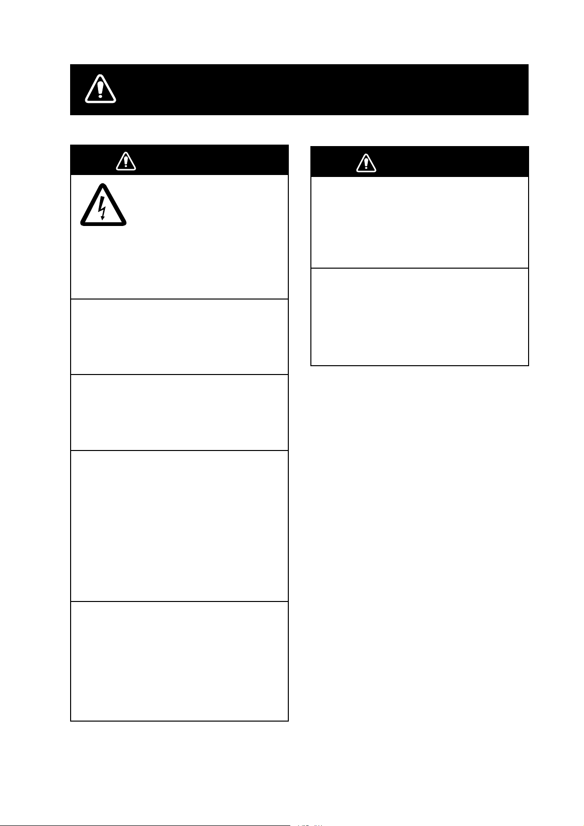
SAFETY INSTRUCTIONS
WARNING
ELECTRICAL SHOCK HAZARD
Do not open the equipment
unless totally familiar with
electrical circuits and
service manual.
Only qualified personnel
should work inside the
equipment.
Turn off the power at the switchboard
before beginning the installation.
Fire or electrical shock can result if the
power is left on.
Do not install the equipment where it
may get wet from rain or water splash.
Water in the equipment can result in fire,
electrical shock or equipment damage.
WARNING
Install the transducer according
to the installation instructions.
Failure to install the transducer correctly
may result in water leakage and damage to
the ship's hull.
For wooden or FRP vessel using a steel
tank, attach a zinc plate to the hull to
prevent electrolytic corrosion.
Electrolytic corrosion can, in the worst
case, result in loss of the transducer.
Be sure no water leaks in at the transducer mounting location.
Water leakage can sink the vessel. Also,
confirm that the transducer will not loosen
by ship's vibration. The installer of the
equipment is solely responsible for the
proper installation of the equipment.
FURUNO will assume no responsibility for
any damage associated with improper
installation.
Be sure that the power supply is
compatible with the voltage rating of
the equipment.
Connection of an incorrect power supply
can cause fire or equipment damage. The
voltage rating of the equipment appears
on the label above the power connector.
i
Page 4
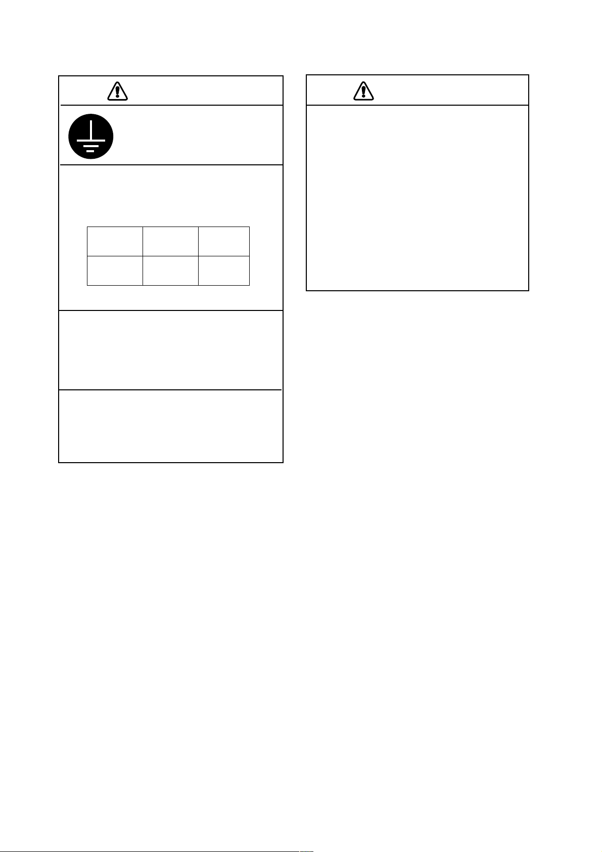
CAUTION
Ground the equipment to
prevent mutual interference.
Observe the following compass safe
distances to prevent interference to a
magnetic compass:
Standard
compass
CV-1100L
Do not allow warm water or any other
liquid other than seawater or freshwater
to contact the transducer.
Damage to the transducer may result.
0.7 m 0.5 m
Steering
compass
CAUTION
The transducer cable must he handled
carefully, following the guidelines
below.
• Keep fuels and oils away from the
cable.
• Locate the cable where it will not be
damaged.
• The cable sheath is made of chloro phrene or polychloride vinyl, which
are easily by damaged plastic solvents
such as toulene. Locate the cable
well away from plastic solvents.
Do not install the transducer where
noise or air bubbles is present.
Performance will be affected.
ii
Page 5

TABLE OF CONTENTS
SYSTEM CONFIGURATION................................................................................iv
EQUIPMENT LISTS ..............................................................................................v
1. MOUNTING ...................................................................................................1-1
1.1 Display Unit...............................................................................................................1-1
1.2 Transducer.................................................................................................................1-4
1.3 Water Temperature Sensor (option)...........................................................................1-4
2. WIRING..........................................................................................................2-1
2.1 Wiring Standard Equipment.......................................................................................2-2
2.2 Wiring Optional Equipment........................................................................................2-3
2.3 Input/Output Sentences.............................................................................................2-3
3. INITIAL SETTING..........................................................................................3-1
3.1 Language Setting.......................................................................................................3-1
3.2 Transducer Data........................................................................................................3-2
3.3 Water Temperature Sensor Setting............................................................................3-7
3.4 Nav Data, Heading Sensor Setting ............................................................................3-9
3.5 Propagation Velocity................................................................................................ 3-11
3.6 Demonstration Mode................................................................................................3-12
3.7 Restoring Default Settings.......................................................................................3-13
APPENDIX 1 TRANSDUCER 50BL-12/50BL-24H ........................................AP-1
APPENDIX 2 NEW BLT TRANSDUCERS......................................................AP-2
PACKING LISTS ............................................................................................... A-1
OUTLINE DRAWINGS...................................................................................... D-1
SCHEMATIC DIAGRAM ....................................................................................S-1
iii
Page 6
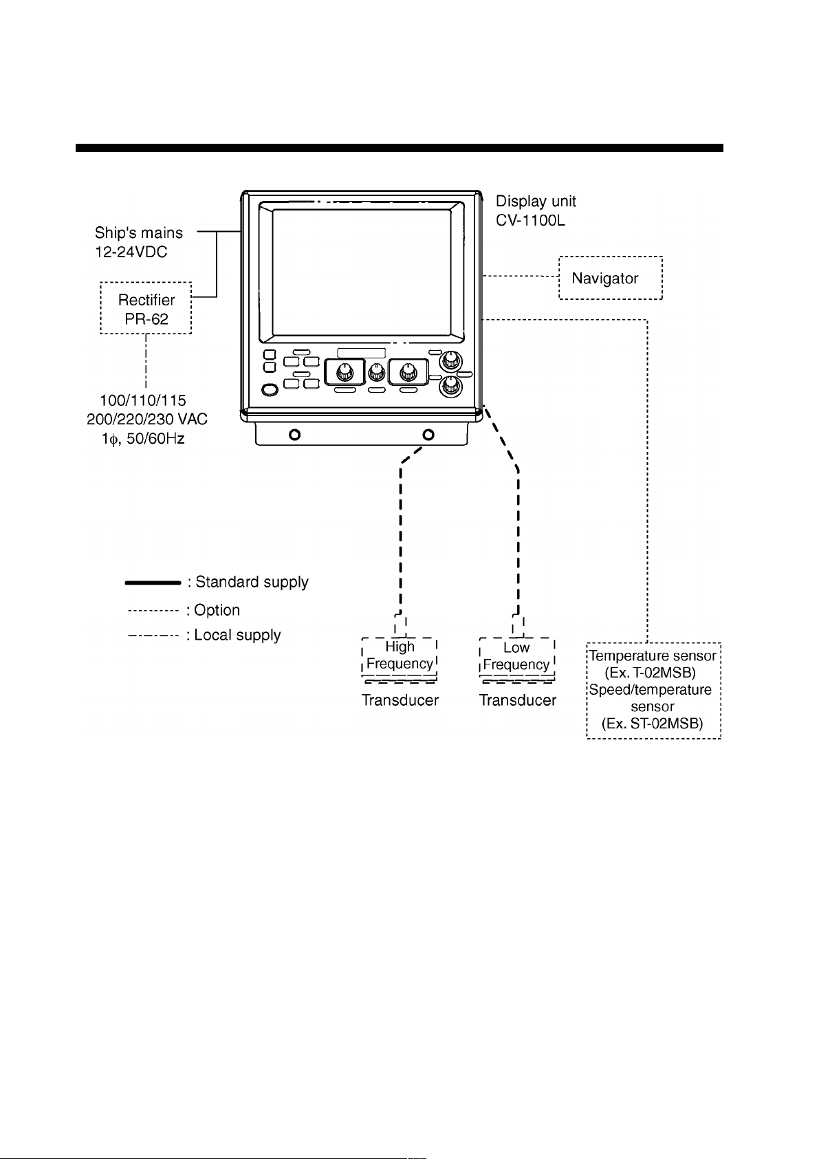
SYSTEM CONFIGURATION
iv
Page 7
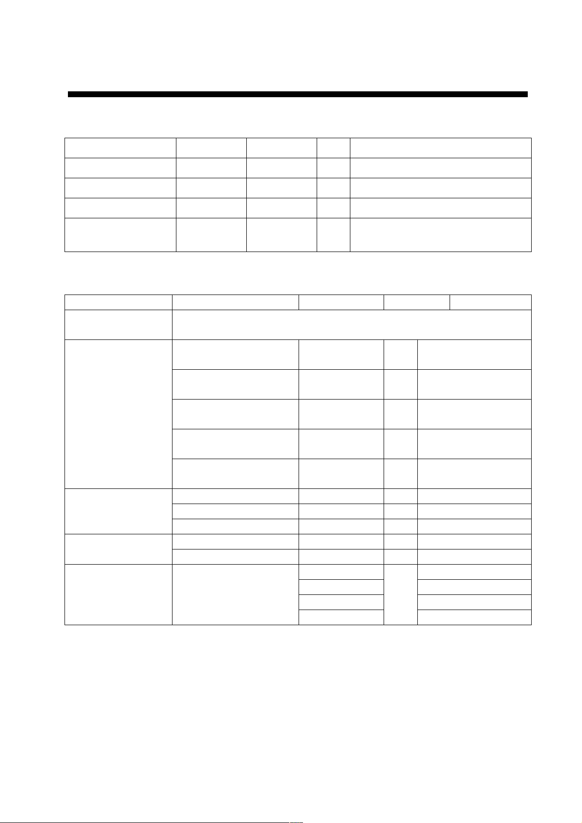
EQUIPMENT LISTS
Standard supply
Name Type Code No. Qty Remarks
Display unit CV-1100L - 1
Spare Parts SP02-04401 001-402-100 1 set Fuse
Accessories FP02-05300 000-012-509 1 set Hood
EQUIPMENT LISTS
Installation Materials
CP02-06900 000-012-508
1 set
MJ-A3SPF0013-035 (3.5 m),
CP02-06901
Options
Name Type Code No. Qty Remarks
Transducer Transducer available in 1, 2 and 3 kW models. See page vi – xiii for
details. No selection also available.
MJ-A6SPF0012-050 000-134-424 1
MJ-A6SPF0012-100 000-133-817 1
Cable Assy
Water Temperature
Sensor
Sensor
Rectifier PR-62
MJ-A6SPF0011-050 000-132-244 1
MJ-A6SPF0011-100 000-132-336 1
NCS255AD-254P-L500 000-142-518 1
T-02MSB 000-040-040 1 Thru-hull mount
T-02MTB 000-040-026 1 Transom mount
T-03MSB 000-040-027 1 Thru-hull mount
ST-02MSB 000-137-986 1 Speed/Temperature
ST-02PSB 000-137-987 1
000-013-484 100 VAC
000-013-485 110 VAC*
000-013-486 220 VAC
000-013-487
*: Use this type for 115 VAC.
6P-6P, 5m, for
navigator
6P-6P, 10m, for
navigator
6P-4P, 5m, for
navigator
6P-4P, 10m, for
navigator
For dual –frequency
transducer
1
230 VAC
v
Page 8

EQUIPMENT LISTS
Available transducers
1 kW transducer
Frequency
(kHz)
28/50
28/68
28/88
28/200
50/88
50/200
68/200
88/200
Hull
Material
Steel - FRP
Steel TWB-6000 (2) T-656
FRP
Steel - FRP
Steel - FRP
Steel TWB-6000 (2) T-657
FRP
Steel - FRP
Steel - FRP
Steel TWB-6000 (2) T-658
FRP
Steel - FRP
Steel - FRP
Steel - FRP
Steel - FRP
Steel - FRP
Steel - FRP
Steel - FRP
Steel - -
FRP
Transducer
28F-8
50B-6/6B
28F-8
50B-9/9B
28F-8
50F-8G
28F-8
68F-8H
28F-8
88B-8
28F-8
200B-5S
50B-6/6B
88B-8
50B-9/9B
88B-8
50F-8G
88B-8
50B-6/6B
200B-5S
50B-9/9B
200B-5S
50F-8G
200B-5S
50/200-1T
50/200-1ST
68F-8H
200B-5S
88B-8
200B-5S
Thru-Hull
Pipe
- -
- -
- -
- -
- -
- -
- -
- -
- -
- -
- -
- -
- -
- -
- -
Tank
- -
vi
Page 9

2 kW transducer
EQUIPMENT LISTS
Frequency
(kHz)
28/50
28/68
28/88
28/200
50/88
50/200
68/200
Hull
Material
Steel TFB-7000 (2) T-634
FRP
Steel - FRP
Steel TFB-7000 (2) T-636
FRP
Steel TFB-7000 (2) T-638
FRP
Steel TFB-7000 (2) T-643
FRP
Steel TFB-7000 (2) T-645
FRP
Steel TFB-7000 (2) FRP
Transducer
28F-18
50B-12
28F-18
68F-30H
28F- 18
88B-10
28F-18
200B-8/8B/8N
50B-12
200B-8/8B/8N
50B-12
200B-8/8B/8N
68F-30H
200B-8/8B/8N
Thru-Hull
Pipe
- -
TRB-1100 (2) T-634-F
TFB-1100 ( 2) T-636-F
TFB-1100 ( 2) T-638-F
TFB-1100 ( 2) T-643-F
- -
TFB-1100 (2) -
Tank
88/200
Steel TFB-7000 (2) T-649
FRP
88B-10
200B-8/8B/8N
TFB-1100 ( 2) T-649-F
vii
Page 10

EQUIPMENT LISTS
3 kW transducer
Frequency
(kHz)
28/50
28/68
28/88
28/107
28/150
28/200
50/88
50/107
50/150
50/200
68/107
68/150
68/200
88/150
88/200
107/200
Hull
Material
Steel TFB-7000 (2) T-681
FRP
Steel - FRP
Steel TFB-7000 (2) T-682
FRP
Steel - FRP
Steel - FRP
Steel - FRP
Steel TFB-7000 (2) T-682
FRP
Steel - FRP
Steel TFB-7000 (2) T-683
FRP
Steel TFB-7000 (2) T-683
FRP
Steel - FRP
Steel TFB-7000 (2) T-646
FRP
Steel TFB-7000 (2) T-646
FRP
Steel - FRP
Steel TFB-7000 (2) T-685
FRP
Steel TFB-7000 (2) FRP
Transducer
28F-24H, 50F-24H
28F-24H, 68F-30H
28F-24H, 88F-126H
28F-24H, 100B-10R
50B-6/6B, 88B-8
28F-24H, 200B-12H
50F-24H, 88F-126H
50F-24H, 100B-10R
50F-24H, 150B-12H
50F-24H, 200B-12H
68F-30H, 100B-10R
68F-30H, 150B-12H
68F-30H, 200B-12H
88F-126H, 150B-12H
88F-126H, 200B-12H
100B-10R, 200B-12H
Thru-Hull
Pipe
TRB-1100 (2) T-681-F
- -
TRB-1100 (2) T-682-F
- -
- -
- -
TRB-1100 (2) T-682-F
- -
TRB-1100 (2) T-683-F
TFB-1100 (2) T-638-F
- -
TFB-1100 (2) T-646-F
TFB-1100 (2) T-646F
- -
TFB-1100 (2) T-685-F
TFB-1100 (2) -
Tank
viii
Page 11

1 kW/2 kW transducer
EQUIPMENT LISTS
Output
(W)
1 k/2 k
Frequency
(kHz)
28/50
28/68
28/88
28/200
50/88
Hull
Material
Steel - FRP
Steel - FRP
Steel - FRP
Steel TWB-6000 (2) T-657
FRP
Steel - FRP
Steel - FRP
Steel TFB-7000 (2) T-636
FRP
Transducer
28F-8
50B-12
28F-8
68F-30H
28F-8
88B-10
28F-8
200B-8/8B/8N
50B-6/6B
88B-10
50B-9/9B
88B-10
50F-8G
88B-10
Thru-Hull
Pipe
- -
- -
- -
- -
- -
- -
TRB-1100 (2) T-636-F
Tank
Steel - FRP
Steel TWB-6000 (2) T-658
50/200
FRP
Steel TFB-7000 (2) T-638
FRP
Steel - -
68/200
FRP
Steel TWB-6000 (2) T-659
88/200
FRP
50B-6/6B
200B-8/8B/8N
50B-9
200B-8/8B/8N
50F-8G
200B-8/8B/8N
68F-8H
200B-8/8B/8N
88B-8
200B-8/8B/8N
- -
- -
TFB-1100 ( 2) T-638-F
- -
- -
ix
Page 12

EQUIPMENT LISTS
1 kW/3 kW transducer
Output
(W)
1 k/3 k
Frequency
(kHz)
28/45
28/50
28/68
28/88
28/150
28/107
28/150
28/200
50/88
50/107
50/150
Hull
Material
Steel - FRP
Steel - FRP
Steel - FRP
Steel - FRP
Steel - FRP
Steel - FRP
Steel - FRP
Steel - FRP
Steel - FRP
Steel - FRP
Steel - FRP
Steel - FRP
Steel - FRP
Steel - FRP
Steel - FRP
Steel - FRP
Steel - FRP
Transducer
28F-8
45F-12H
28F-8
50F-24H
28F-8
68F-30H
28F-24H,
100B-10R
28F-8
88F-126H
28F-8
100B-10R
28F-8
150B-12H
28F-8
200B-12H
50B-6/6B
88F-126H
50B-9B
88F-126H
50F-8G
88F-126H
50B-6/6B
100B-10R
50B-9/9B
100B-10R
50F-8
100B-10R
50B-6/6B
150B-12H
50B-9/9B
150B-12H
50F-8G
150B-12H
Thru-Hull
Pipe
- -
- -
- -
- -
- -
- -
- -
- -
- -
- -
- -
- -
- -
- -
- -
- -
- -
Tank
x
Page 13

Output
(W)
1 k/3 k
Frequency
(kHz)
50/200
68/107
68/150
68/200
88/150
88/200
EQUIPMENT LISTS
Hull
Material
Steel - FRP
Steel - FRP
Steel - FRP
Steel - FRP
Steel - FRP
Steel - FRP
Steel - FRP
Steel - FRP
Transducer Thru-Hull Pipe Tank
50B-6/6B
200B-12H
50B-9/9B
200B-12H
50F-8G
200B-12H
68F-8H
100B-10R
68F-8H
150B-12H
68F-8H
200B-12H
88B-8
150B-12H
88B-8
200B-12H
- -
- -
- -
- -
- -
- -
- -
- -
xi
Page 14

EQUIPMENT LISTS
2 kW/3 kW transducer
Output
(W)
2 k/3 k
Frequency
(kHz)
28/45
28/50
28/68
28/88
28/107
28/150
28/200
50/88
50/107
50/150
50/200
68/107
68/150
68/200
88/150
88/200
Hull
Material
Steel - FRP
Steel - FRP
Steel - FRP
Steel - FRP
Steel TFB-7000 (2) T-636
FRP
Steel TFB-7000 (2) T-637
FRP
Steel - FRP
Steel - FRP
Steel TFB-7000 (2) T-643
FRP
Steel TFB-7000 (2) T-644
FRP
Steel - FRP
Steel - FRP
Steel - FRP
Steel - FRP
Steel - FRP
Steel - FRP
Transducer Thru-Hull Pipe Tank
28F-18
45F-12H
28F-18
50F-24H
28F-18
68F-30H
28F-18
88F-126H
28F-18
100B-10R
28F-18
150B-12H
28F-18
200B-12H
50B-12
88F-126H
50B-12
100B-10R
50B-12
150B-12H
50B-12
200B-12H
68F-30H
100B-10R
68F-30H
150B-12H
68F-30H
200B-12H
88B-10
150B-12H
88B-10
200B-12H
TRB-1100 (2) T-636-F
TRB-1100 (2) T-637-F
TRB-1100 (2) T-643-F
TRB-1100 (2) T-644-F
- -
- -
- -
- -
- -
-
- -
- -
- -
- -
- -
- -
xii
Page 15

3 kW/2 kW transducer
EQUIPMENT LISTS
Output
(W)
3 k/2 k
Frequency
(kHz)
28/50
28/68
28/88
28/200
50/88
50/200
68/200
88/200
107/200
Hull
Material
Steel - FRP
Steel - FRP
Steel - FRP
Steel - FRP
Steel - FRP
Steel - FRP
Steel TFB-7000 (2) T-647
FRP
Steel - FRP
Steel TFB-7000 (2) T-649
FRP TRB-1100 (2) T-649-F
FRP
Transducer Thru-Hull Pipe Tank
28F-24H
50B-12
28F-24H
68F-30H
28F-24H
88B-10
28F-24H
200B-8/8B/8N
50F-24H
88B-10
50F-24H
200B-8/8B/8N
68F-30H
200B-8/8B/8N
88F-126H
200B-8/8B/8N
100B-10R
200B-8/8B/8N
TRB-1100 (2) T-645-F
- -
- -
- -
- -
- -
- -
-
- -
xiii
Page 16

EQUIPMENT LISTS
This page is intentionally left blank.
xiv
Page 17

1. MOUNTING
1.1 Display Unit
Turn off the power at the switchboard
before beginning the installation.
Fire or electrical shock can result if the
power is left on.
Mounting considerations
WARNING
• Locate the unit out of direct sunlight.
• The operator should face the bow while viewing the display screen.
• Select a location where the display screen can be easily observed while operating the control
unit.
• Leave sufficient space around the unit for maintenance and servicing. Recommended
maintenance space appears in the outline drawing at the back of this manual.
1-1
Page 18

1. MOUNTING
Mounting procedure
Desktop mounting
1. Loosen two M6 x 25 bolts at the front of t he display unit to remove the mounting base.
M6 x 25 bolts
Removing the display unit from the mounting base
2. Use the four tapping screws (5 x 20, supplied as installation materials) to fasten the
mounting base.
3. Apply grease to the bolts removed at step 1.
4. Lay the display unit on the m ounting base. Fasten the display unit to the mounting base
with the two M6 x 25 bolts greased at step 3.
1-2
Page 19

1. MOUNTING
Flush mounting
1. Make cutout in mounting location referring to the outline drawing show below.
2. Fasten the display unit to the m ounting location with four pan head screws.
Flush mounting display unit
1-3
Page 20

1. MOUNTING
1.2 Transducer
The performance of the video sounder depends upon the transducer position. A place least
affected by air bubbles should be selected since turbulence blocks t he sounding path.
Further, select a place least influenced by engine noise. It is known that air bubbles are
fewest at the place where the bow first falls and the next wave rises, at usual cruising
speed.
Note: The face of the transducer must be facing the sea bottom in normal cruising trim of the
boat.
1.3 Water Temperature Sensor (option)
Transom mount water temperature sensor T-02MTB
• Fix the cable at a convenient location
on the transom with the cable clamp.
• When the cable is led through the
transom board, make a hole of
approx. 17 mm in diameter to pass
the connector. After passing the
cable, seal the hole with a sealing
compound.
How to mount transom mount water
temperature sensor T-02MTB
D>50 cm
D
5X20
Flush with hull bottom
1-4
Page 21

1. MOUNTING
Thru-hull mount water temperature sensor T-02MSB, T-03MSB
• Select a suitable mounting location considering the following points:
• Select a mid-boat flat position. The sensor does not have to be installed perfectly
perpendicular; however, the location should not be such that the transducer may be damaged
when the boat is dry-docked.
• Locate away from equipment which gives off heat.
• Locate away from drain pipes.
• Select a location where vibration is minimal.
T-02MSB T-03MSB
Sensor Holder
Sensor
cable
Locknut
Washer
Gasket
Locknut
Locknut
φ21 mm
Coat with
sealant.
Mounting procedure
1. Drill a hole of 21 mm in diameter in
the mounting location.
2. Pass the sensor cable through the
hole.
3. Pass gasket, washer and locknut
onto cable in that order.
4. Coat the sensor flange with high
quality sealant and then fasten the
sensor with the locknut.
(Torque: max. 59N·m)
5. Launch the boat to check for water
leakage around the sensor.
Washer
Gasket
φ25 mm
Coat with
sealant.
Plate thick-
Holder Guide
Mounting procedure
1. Drill a hole of 25 mm in diameter in the mounting
location.
2. Coat holder guide with high quality sealant, and
pass gasket, washer and locknut onto holder
guide in that order and then tighten the locknut.
3. Set the sensor holder to the holder guide from
inside the boat and then tighten the locknut.
4. Launch the boat to check for water leakage
around the sensor.
ness within
25 mm
Assembling thru-hull water temperature sensor T-02MSB, T- 03MSB
1-5
Page 22

1. MOUNTING
Through-hull mount water temperature/speed sensor
ST-02MSB, ST02-PSB
Select a suitable mounting location consider ing the following:
• Select a mid-boat flat position. The sensor does not have to be installed perfectly
perpendicular. The sensor must not be damaged in dry-docking operation.
• Select a place apart from equipment generating heat.
• Select a place in the forward direction viewing from the drain hole, to allow for circulation of
cooling water.
• Select a place free from vibration.
1. Dry-dock the boat.
2. Make a hole of approx. 51 mm diam eter.
3. Unfasten locknut and remove the sensor section.
4. Apply high-grade sealant to the flange of the sensor.
5. Pass the sensor casing through the hole.
6. Face the notch on the sensor toward boat’s bow and tighten the flange.
7. Set the sensor section to the sensor casing and tighten the locknut.
8. Launch the boat and check for water leakage ar ound the sensor.
Locknut
Face "notch"
toward bow.
Flange nut
Coat with
silicone sealant.
Water temperature/speed sensor ST-02MSB, ST-02PSB
Brim
51
φ77
123
1-6
Page 23

2. WIRING
Refer to the interconnection diagram at the back of this manual for detailed information.
Wiring diagram for standard-type FCV-1100L
2-1
Page 24

2. WIRING
2.1 Wiring Standard Equipment
Transducer
Separate the transducer cable well away from power cables to prevent interference.
Connect the cable to the transducer connector at the rear of the display unit. Fabricate the
cable as below.
Sheild
Connector
NCS-254-P
Fabrication of transducer cable
Note 1: For connection of dual-frequency transducer, use cable assy.
NCS255AD-254P-L500 (option).
Note 2: Do not connect the transducer of 38 kHz or lower
Note 3: FCV-1100L cannot accept the transducers of 54 – 64 kHz, 112 – 122 kHz and 171
– 181 kHz.
Cable clamp
Shield form
Cable
to the high frequency connector.
Power cable
This video sounder is designed to be powered with 12-24 VDC power. Use the cable assy
MJ-A3SPF0013-035 (supplied as installation m aterial).
Ground
The display unit should be grounded to prevent mutual interference. Connect an earth wire
(2 sq, local supply) between unit and ship’s superstructure t o ground. The length of the
earth wire should be as short as possible.
CAUTION
Ground the equipment to
prevent electrical shock
and mutual interference.
2-2
Page 25

2. WIRING
2.2 Wiring Optional Equipment
Navigator
Use cable type MJ-A6SPF0011/0012 (option) to connect the navigator to the NMEA
connector.
Water temperature sensor T-02MSB, T-02MTB, T-03MSB
Connect the water temperature sensor cable to the TEMP connector.
2.3 Input/Output Sentences
Input sentences
Sentence Data Remarks
BWC Range/bearing to waypoint
GGA Time, position
GLC GRI, TD (Loran C)
GLL Latitude and longitude
GTD TD (Loran C)
MTW Water temperature
RMA Latitude and longitude, TD, ground speed and course by a LORAN-C receiver
RMB Recommended minimum navigation information
RMC Latitude and longitude, speed over ground and course over by a GPS
VHW True/magnetic bearing, speed through water Great circle
VTG Speed through the ground and course
XTE Cross track error
Output sentences
Sentences Talker Data Remarks
DBS SD Depth below sea surface Ver. 1.5
DBT SD Depth below transducer Ver. 1.5
DPT SD Depth below transducer Ver. 2.0
MTW YC Water temperature Ver. 1.5 Ver. 2.0 with connection of water
temperature sensor
TLL SD Marker line position Ver. 2.0
VRM SD VRM depth
VHW VW Ship’s speed
2-3
Page 26

2. WIRING
This page is intentionally left blank.
2-4
Page 27

3. INITIAL SETTING
This section provides the informat ion necessary for initial setup of the equipment. First turn
on the power and set display language. I n addition, either transducer used, by model
number (FURUNO transducer only) or by specificat ions.
3.1 Language Setting
1. Turn on the power. The following display appears.
Please set language.
([ / ]: Select, [+]: Enter)
XXXXXXXX
XXXXXXXX
English
XXXXX
2. Press [!] to select English, and then press t he [+] key to set. The following display
appears. For other languages, select appropriately.
Carrry out transducer setting.
Press any key to go to Transducer setting menu.
3. Set transducer type. Then, go to applicable section (s) by pressing any key.
(For Japanese customers)
(Japanese)
Initial display screen
3-1
Page 28

3. INITIAL SETTINGS
3.2 Transducer Data
CAUTION
Set the transducer model number
properly.
Wrong transducer setting can damage the
transducer and void the warranty.
The following models are programmed in the FCV-1100L.
Maker Frequency Type Remarks
Simrad 38 kHz 38E-9-18S1 (2kW)
Airmar 38 kHz 38E-M42 (3 kW)
36 kHz 32/40 (3 kW)
41 kHz 40/75 (3 kW)
Honda
50 kHz
50/200/400 (2 kW)
50/3K/3F (3 kW)
Do not enter transducer data by specifications if model number of transducer
used is programmed in the equipment.
Wrong transducer setting can damage the
transducer and void the warranty.
CAUTION
67 kHz 40/75 (3 kW)
200 kHz 50/200/400 (2 kW)
Suzuki 50, 200 kHz TGM50/200 Same as Furuno makes 50/200-1T (1 kW)
3-2
Page 29

3. INITIAL SETTINGS
Entering transducer data by transducer model number
Note 1: If you are continuing from paragraph 3.1 go to step 2.
Note 2: If you ha ve alre ady entered transducer settings and to reconfirm them turn on the
power while pressing any key.
1. Turn on the power.
2. Press any key to show the following menu.
XDCR SELECT INSTALLATION DEMO
XDCR SELECT : XDCR TYPE
[HIGH]
CONNECTION : NOT CONNECTED
FREQ : ---kHz
TRANSDUCER : ---TAP : --
[LOW]
CONNECTION : NOT CONNECTED
FREQ : --- kHz
TRANSDUCER : ---TAP : --
POWER REDUCTION : OFF
[-/+]: Change setting, Turn OFF to exit
Installation main menu
Note: XDCR SETTING is set to “XDCR TYPE” at the default setting.
3-3
Page 30

3. INITIAL SETTINGS
3. Press [!] to select [HIGH] CONNECTION or [LOW] CONNECTION (whichever is
installed), and then press [+] or [-] to show the dialog box. Select CONNECTED for the
connection of transducer.
4. Press ["] or [!] to close the dialog box.
5. Press [!] to select FREQ.
6. Press [+] or [-] to show the dialog box. The scroll bar at the bott om of the dialog box
shows cursor position in relation to the entire menu.
41 kHz 45 kHz 50 kHz 67 kHz 68 kHz 88 kHz 107 kHz 150kHz
Scroll bar
7. Press [+] or [-] to select frequency, (HIGH: 41 kHz and higher, LOW: 28 kHz and higher
are available.) and then press ["] or [!] to close the dialog box.
8. Press [!] to select TRANSDUCER, and then press [+] or [-] to open the dialog box.
200B-5S (1kW) 50/200-1ST (1kW) 50/200-1T (1 kW) 200B-8/8B (2 kW)
Dialog box for 200 kHz
9. Press [+] or [-] to select model number, and then press ["] or [!] to close the dialog
box.
10. Jot down alphabet which appears on “TAP” line. You may change the terminal board
setting at the rear of the display unit depending on the transducer type which is
connected. For details, see page 3-5.
11. Follow steps 3-10 to enter model number of other transducer if installed.
Note: For dual-frequency transducer, enter both high and low frequencies and set the
same transducer model number for both high and low frequencies.
12. Press [!] to select PWR REDUCTION, and then press [+] or [-] to open t he dialog box.
OFF ON
13. Press [+] or [-] to t urn t he power reduction ON or OFF (default setting).
14. Press ["] or [!] to close the dialog box.
15. Confirm settings and turn off the power.
Note: If the system det ect s frequency mismatch the message “Frequency unmatch error!
Press any key to go to Transducer setting menu.” appears at the next powering of the
equipment. Press any key to go to the transducer setting menu and reenter
transducer data.
3-4
Page 31

3. INITIAL SETTINGS
Transducer setting
Change the term inal board setting at the rear of the display unit according to the tr ans ducer
connected.
Note the alphabet which appeared when selecting the transducer type on the installation
main menu (p age 3-4), and then do the f ollowing procedures.
1. Dismount t he display unit from the mounting place.
2. Loosen four sc r ews to remove the rear cover.
Note: There is no gasket for lid. (The groove around the terminal board does not hold a
gasket.)
12-24_VDC
NMEA
TEMP
H
L
Loosen these screws.
Display unit, rear view
3. Fasten the cr imp-on lug to the appropriate terminal according to alphabet appearing on
the installation menu.
A
BCDE
TB10
TB9 TB8 TB7 TB6
L
H
ABCDE
TB5 TB4
TB3
TB2 TB1
For Low F requency
4. Remount the display unit.
For High F requency
Terminal board
3-5
Page 32

3. INITIAL SETTINGS
Entering transducer data by transducer specifications
For dealer: When connecting the t r ansducers which are not programmed, contact to
PRODUCT SERVICE SECTION SERVICE CENTER, FURUNO HEAD OFFICE. For new
transducer or other make of transducer see FURUNO information for further information.
Note 1: If you are continuing from paragraph 3.1, go to step 2.
Note 2: If you ha ve already entered transducer settings and wait to reconfirm them turn on
the power while pressing any key.
Note 3: The tr ansducers of 54 – 64 kHz, 112 – 122 kHz and 171 – 181 kHz
connected to the FCV-1100L because of noise. (Available range: HIGH; 40 – 220
kHz, LOW; 25 –220 kHz).
1. Turn on the power.
2. Press any key.
3. Press ["] to select XDCR SELECT, and then press [ +] or [-] to show the dialog below.
XDCR TYPE MANUAL
cannot be
4. Press [+] to select MANUAL, and then press [!] or ["] to close the dialog box. The
display should now look something like t he one below.
XDCR SELECT INSTALLATION DEMO
XDCR SELECT : MANUAL
[HIGH]
CONNECTION : NOT CONNECTED
FREQ : ---kHz
[LOW]
CONNECTION : NOT CONNECTED
FREQ : --- kHz
POWER REDUCTION : OFF
Select how to set XDCR type.
[-/+]: Change setting, Turn OFF to exit
Menu for manual entry of transducer specifications
5. Do the following for both the high and low frequency transducers, or whichever
transducer is installed.
a) Press ["] to select CONNECTION of [HIGH] or [LOW], and then press [+] or [-] to open
the dialog box.
NOT CONNECTED CONNECTED
b) Use [+] or [-] to select CONNECTED, and then press [!] or ["] to close the dialog box.
c) Press ["] to select FREQ, and press [+] or [-] to display the frequency setting dialog box.
--- kHz
3-6
Page 33

3. INITIAL SETTINGS
d) Use [+] or [-] to set the value for the frequency which is connected, and then press [!] or
["] to close the dialog box. (Available range: HIGH; 40 – 220 k Hz, LOW; 25 – 220 kHz)
e) To operate the t r ansducer in reduced power (for example, when vessel is in dry dock),
press ["] to select PWR REDUCTION, and then press [+] or [-] to open the dialog box.
OFF ON
f) Press [+] or [-] to tur n t he power reduct ion ON, and t hen press [!] or ["] to close the
dialog box.
6. Confirm settings and turn off the power.
3.3 Water Temperature Sensor Setting
If a water temperature sensor is connected, set up as follows:
1. Turn on the power and turn the [FUNCTION] switch to the MENU position.
2. Press [!] and [+] to select SYSTEM at t he top of the screen.
3. Press ["] to select TEMP SET TING, and then press [+] to open that menu.
DISP ALM TX/RX E/S SYSTEM
TEMP SETTING
TEMP UNIT : ˚F
TEMP INPUT : SENSOR
TEMP ADJUST : +0.00˚F (-20 +20)
TEMP OUTPUT : OFF
TEMP READOUT : OFF
TEMP GRAPH : OFF
TEMP COLOR : STD
Select temperature unit.
[-/+]: Change set, [EXIT]: Exit
TEMP SETTING menu
4. The cursor is selecting TEMP UNIT; press [+] or [-] to open the dialog box.
C F
5. Press [+] or [-] to select the temperature unit, and then press [!] or ["] to close the
dialog box.
3-7
Page 34

3. INITIAL SETTINGS
6. Press ["] to select TEMP INPUT, and then press [+] or [-] to open the dialog box.
SENSOR NMEA
7. Use [+] or [-] to select source of water temperature data, and t hen press [!] or ["] to
close the dialog box.
SENSOR: Water temperature sensor T-02MSB, T-02MTB or T-03MSB inputs water
temperature data. This is the default setting.
NMEA: Water temperature data input from external equipment.
8. When selecting SENSOR at TEMP INPUT, you may offset water temperature data to
further refine its accuracy. This must be done with the boat in water.
a) Press ["] to select TEMP ADJUT, and then press [+] or [-] to open the dialog box.
+0.00
b) Watch the water temperature readout on the monitor (if it is not displayed set TEMP
READOUT to ON) and compare it with known value.
c) Use [+] or [-] to enter the difference found in b) above. For example, if the indication of
the FCV-1100L is +5° higher than the actual value, enter –5 (degree).
d) Press [!] or ["] to close the dialog box.
9. Press ["] to select TEMP OUTPUT, and then press [+] or [-] to open the dialog box.
OFF ON
10. Use [-] or [+] to turn the water temperature indication (NMEA) ON or OFF respectively,
and then press [!] or ["] to close the dialog box.
11. Press ["] to select TEMP READOUT, and then press [+] to open the dialog box.
OFF ON
12. Use [-] or [+] to select the temperat ure display, and press [!] or ["] to close the dialog
box.
13. Press ["] to select TEMP GRAPH and [+] or [-] to open the dialog box.
OFF NARROW STD EXPAND
14. Press [+] or [-] to select temperat ure scale graduation interval, and then press [!] or ["]
to close the dialog box.
15. Press ["] to select TEMP COLOR and [+] or [-] to open the dialog box.
STD WHITE RED BLACK YELLOW
16. Use [+] or [-] to select the color of the water temperature graph for STD (blue in default
setting but then press [!] or ["] to close the dialog box.
17. Turn the [FUNCTION] switch to EXIT position to quit.
3-8
Page 35

3. INITIAL SETTINGS
3.4 Nav Data, Heading Sensor Setting
Select navigator and heading sensor used as below.
1. Turn on the power and turn the [FUNCTION] switch to the MENU position.
2. Press [!] and [+] to select SYSTEM at t he top of the screen.
3. Press ["] to select NAV DATA SETTING, and then press [+] to open that menu. (If a
heading sensor is connected but not a navigator, go to step 18.)
DISP ALM TX/RX E/S SYSTEM
NAV DATA SETTING
SPEED UNIT : kt
SPEED INPUT : SENSOR
SPEED ADJUST : +0% (-50 +50)
SPEEDOUTPUT : ON
SPEED INFO : OFF
NMEA VERSION : Ver 2.0
NAV DATA : AUTO
COURSE : TRUE
TLL OUTPUT : OFF
Select speed unit.
[-/+]: Change set, [EXIT]: Exit
NAV DATA SETTING menu
4. The cursor is selecting SPEED UNIT; press [+] or [ - ] to open the dialog box.
kt km/h MPH
5. Use [-] or [+] to select the speed unit , and then press [!] or ["] to close the dialog box.
6. Press ["] to select SPEED INPUT, and then press [+] or [-] to open the dialog box.
SENSOR NMEA
7. Use [+] or [-] to select the source of speed data, and then press the [!] or ["] to close
the dialog box.
SENSOR: Speed/temperature sensor
NMEA: Speed data input from t he equipment connected.
8. Press ["] to select SPEED ADJUST, and the press [+] to open the dialog box.
+0.0
9. You may offset speed data to further refine its accuracy. This is not possible when the
speed input is “NMEA”.
a) Watch the speed sensor readout on the monitor (if it is not displayed set SPEED INFO
to ON) and compare it with known value.
b) Use [+] or [-] to enter the difference found in a) above. For example, if the indication of
the FCV-1100L is +5 % faster than the actual value, enter –5.
3-9
Page 36

3. INITIAL SETTINGS
Adjustment value =
c) Press [!] or ["] to close the dialog box.
Actual value - Indication of FCV-1100L
Actual value
x 100 (%)
10. Press ["] to select SPEED OUTPUT, and t hen press the [+] or [-] key to open the dialog
box.
OFF ON
11. Use [+] or [-] to turn the speed output ON (default setting) or OFF, and press [!] or ["]
to close the dialog box.
12. Press ["] to select SPEED INFO, and then press [+] or [-] to open the dialog box.
OFF ON
13. Press [+] or [-] to turn the speed indication (NMEA) O FF (default setting) or ON, and
then press [!] or ["] to close the dialog box. If no navigator is connected, turn the
[FUNCTION] switch to other position to quit.
14. Press ["] to select NMEA VERSION, and then press [+] or [-] to open the dialog box.
Ver 1.5 Ver 2.0 Ver 3.0 SPECIAL
15. Use [+] or [-] to select NMEA version no. (default setting is Ver 2.0) of the navigator, and
then press [!] or ["] to close the dialog box. If you are unsure of the version no., try all
three to see which one successfully receives position data. SPECIAL is for use with a
navigator whose baud rate is 600 bps.
16. Press ["] to select NAV DATA, and then press [+] or [-] to open the dialog box.
LC LA DECCA GPS DR AUTO
17. Use [+] to select type of navigat or connected, and then press [!] or ["] to close the
dialog box. AUTO (default setting) selects a navigator in the order of GPS, Loran C,
Loran A, Decca, DR (Dead Reckoning).
18. Press ["] to select COURSE, and then press [+] or [-] to open the dialog box.
TRUE MAG
19. Use [+] or [-] to select TRUE or MAG (magnetic bearing) as appropriate , and then press
[!] or ["] to close the dialog box. TRUE is the default setting.
20. Press["] to select TLL (Target latitude, Longitude) OUTPUT, and then press [+] or [-] to
open the dialog box.
OFF ON
21. TLL OUTPUT enables or disables output of position data from t he video sounder to
external equipment, at the moment the [MARKER TLL] key is pressed. Use [+] or [-] to
select ON or OFF (default setting) as appropriate, and t hen press [!] or ["] to close the
dialog box.
22. Turn the [FUNCTION] switch to EXIT position to quit.
3-10
Page 37

3. INITIAL SETTINGS
3.5 Propagation Velocity
This section provides the informat ion for adjustment of propagation velocity. Normally, no
adjustment is necessary, however if the depth indication is wrong, lower or raise
propagation velocity as appropriate.
1. Turn on the power while pressing any key to show the installation main menu.
2. Press [+] or [-] to select INSTALLATION.
XDCR SETTING INSTALLATION DEMO
SOUND SPEED : 1500.0 m/s (200~2000)
INVERTER FREQ : LO (59/118/177 kHz)
[-/+]: Change setting, Turn OFF to exit
INSTALLATION menu
3. Press ["] to select SOUND SPEED, and then press [+] or [-] to open the dialog box.
1500.0 m/s
4. Use [+] or [-] to enter value, and then press [!] or ["] to close the dialog box. The
default setting is 1500.0 (m/ s ) and the setting range is 200-2000 (m/s9.
5. Turn off the power to quit.
3-11
Page 38

3. INITIAL SETTINGS
3.6 Demonstration Mode
The demonstration mode provides a simulated video sounder picture. Connection of the
transducer is not necessary. All controls are operational.
1. Turn on the power while pressing any key to display the installation main m enu.
2. Press [+] to select DEMO.
XDCR SETTING INSTALLATION DEMO
DEMO MODE : OFF
[-/+]: Change setting, Turn OFF to exit
DEMO menu
3. Press ["] to select DEMO MODE, and then press [+] or [-] to open the dialog box.
OFF ON
4. Use [+] or [-] to select ON or OFF (default setting) as appropriate, and then press [!] or
["] to close the dialog box.
5. Turn off the power.
6. Turn on the power again after five seconds. “<DEMO>” appears at the bottom of the
screen when the demonstration mode is on.
3-12
Page 39

3. INITIAL SETTINGS
3.7 Restoring Default Settings
The procedure below restores most default set tings. Are not affected: target setting,
language, demo mode, transducer sett ings, user color settings and user clutter settings.
1. Turn on the power and turn the [FUNCTION] switch to the MENU position.
2. Press [!] and [+] to select SYSTEM at the top of the screen.
3. Press ["] to select DEFAULT SETTING, and then press [+] key.
DISP ALM TX/RX E/S SYSTEM
DEFAULT SETTING
DEF A ULT SET : NO
[-/+]: Change set, [EXIT]: Exit
4. Press [+] or [-] to open the dialog box.
[-]: NO [+]: YES
5. Press [+] to restore default settings.
6. Three beeps sound and then normal operation i s restored.
3-13
Page 40

This page is intentionally left blank .
Page 41

APPENDIX 1 TRANSDUCER 50BL-12/50BL-24H
When using the transducer 50BL-12/ 50BL-24H, see this appendix.
Transducer, thru-hull pipe and tank list
Frequency
(kHz)
50/200 50BL-12/200B-8B
28/50 28F-24H/50BL-24H
50/88 50BL-24H/88F-126H
50/200 50BL-24H/200B-12H
Transducer
Material
Steel
FRP
Steel
FRP
Steel
FRP
Steel
FRP
Settings
Hull
Tank
(Code No.)
T-693
(000-015-044)
T-693F
(000-015-241)
T-696
(000-015-048)
T-696F
(000-015-244)
T-697
(000-015-239)
T-697F
(000-015-245)
T-695
(000-015-047)
T-695F
(000-015-243)
Fasten inside
hull (Code No.)
TWB-6000
(000-015-207)
TWB-1100
(000-015-218)
TWB-6000
(000-015-207)
TRB-1100
(000-015-218)
TWB-6000
(000-015-207)
TRB-1100
(000-015-218)
TWB-6000
(000-015-207)
TRB-1100
(000-015-218)
Fasten outside
hull (Code No.)
TFB-7000
(000-015-209)
-
TFB-7000
(000-015-209)
-
TFB-7000
(000-015-209)
-
TFB-7000
(000-015-209)
-
1. Referring page 3-6, set the menu as below.
XDCR SELECT: MANUAL
FREQ: 50 kHz
2. At the term inal board at the rear of the display unit, fasten the c r imp-on lug to C positi on.
(See page 3-5.)
Frequency Output (kW) Transducer Terminal
2 50BL-12 C
50
3 50BL-24H C
AP-1
Page 42

APPENDIX 2 NEW BLT TRANSDUCERS
A new type BLT transduc er ( B olt-clamp Langevin Transducer) has been developed for this
echo sounder. The BLT transducer has large bandwi dth, good sound efficiency, compact
structure and is reinforced for protection against s lamming.
Transducer, thru-hull pipe and tank list
Frequency
(kHz)
28/200 28BL-6HR/200B-8B
38/200 38BL-9HR/200B-8B
50/200 50BL-12HR/200B-8B
28/38 28BL-12HR/38BL-15HR
28/50 28BL-12HR/50BL-24HR
Transducer
Hull
Material
Steel
FRP
Steel
FRP
Steel
FRP
Steel
FRP
Steel
Tank
(Code No.)
T-693
(000-015-044)
T-693F
(000-015-241)
T-693
(000-015-044)
T-693F
(000-015-241)
T-693
(000-015-044)
T-693F
(000-015-241)
T-681
(000-015-849)
T-681F
(000-015-850)
T-681
(000-015-849)
Fasten inside
hull (Code No.)
TWB-6000 (2)
(000-015-207)
TRB-1100 (2)
(000-015-219)
TWB-6000 (2)
(000-015-207)
TRB-1100 (2)
(000-015-219)
TWB-6000 (2)
(000-015-207)
TRB-1100 (2)
(000-015-219)
TWB-6000 (2)
(000-015-207)
TRB-1100 (2)
(000-015-219)
TWB-6000 (2)
(000-015-207)
Fasten outside
hull (Code No.)
TFB-7000 (2)
(000-015-209)
-
TFB-7000 (2)
(000-015-209)
-
TFB-7000 (2)
(000-015-209)
-
TFB-7000 (2)
(000-015-209)
-
TFB-7000 (2)
(000-015-209)
FRP
38/50 38BL-15HR/50BL-24HR
28/88 28BL-12HR/88F-126H
38/88 38BL-15HR/88F-126H
AP-2
Steel
FRP
Steel
FRP
Steel
FRP
T-681F
(000-015-850)
T-681
(000-015-849)
T-681F
(000-015-850)
T-682
(000-015-851)
T-682F
(000-015-852)
T-682
(000-015-851)
T-682F
(000-015-852)
TRB-1100 (2)
(000-015-219)
TWB-6000 (2)
(000-015-207)
TRB-1100 (2)
(000-015-219)
TWB-6000 (2)
(000-015-207)
TRB-1100 (2)
(000-015-219)
TWB-6000 (2)
(000-015-207)
TRB-1100 (2)
(000-015-219)
-
TFB-7000 (2)
(000-015-209)
-
TFB-7000 (2)
(000-015-209)
-
TFB-7000 (2)
(000-015-209)
-
Page 43

A
50/88 50BL-24HR/88-126H
Steel
APPENDIX 2 NEW BLT TRANSDUCERS
T-682
(000-015-851)
TWB-6000 (2)
(000-015-207)
TFB-7000 (2)
(000-015-209)
FRP
28/200 28BL-12HR/200B-12H
38/200 38BL-15HR/200B-12H
50/200 50BL-24HR/200B-12H
28/150 28BL-12HR/150B-12H
38/150 38BL-15HR/150-12H
Steel
FRP
Steel
FRP
Steel
FRP
Steel
FRP
Steel
T-682F
(000-015-852)
T-683
(000-015-853)
T-683F
(000-015-854)
T-683
(000-015-853)
T-683F
(000-015-854)
T-683
(000-015-853)
T-683F
(000-015-854)
T-683
(000-015-853)
T-683F
(000-015-854)
T-683
(000-015-853)
TRB-1100 (2)
(000-015-219)
TWB-6000 (2)
(000-015-207)
TRB-1100 (2)
(000-015-219)
TWB-6000 (2)
(000-015-207)
TRB-1100 (2)
(000-015-219)
TWB-6000 (2)
(000-015-207)
TRB-1100 (2)
(000-015-219)
TWB-6000 (2)
(000-015-207)
TRB-1100 (2)
(000-015-219)
TWB-6000 (2)
(000-015-207)
-
TFB-7000 (2)
(000-015-209)
-
TFB-7000 (2)
(000-015-209)
-
TFB-7000 (2)
(000-015-209)
-
TFB-7000 (2)
(000-015-209)
-
TFB-7000 (2)
(000-015-209)
T-683F
(000-015-854)
T-683
(000-015-853)
T-683F
(000-015-854)
38/150 50BL-24HR/156-12H
FRP
Steel
FRP
Settings
1. Referring page 3-6, set the menu as below.
XDCR SELECT: MANUAL
FREQ: 28/38/50 kHz
Transducer Output Tap
28BL-6HR C
38BL-9HR C
50BL-12HR
28BL-12HR D
2
C
TRB-1100 (2)
(000-015-219)
TWB-6000 (2)
(000-015-207)
TRB-1100 (2)
(000-015-219)
-
TFB-7000 (2)
(000-015-209)
-
38BL-15HR E
50BL-24HR
3
E
P-3
Page 44

APPENDIX 2 NEW BLT TRANSDUCERS
This page is intentionally left blank.
AP-4
Page 45

Page 46

Page 47

Page 48

Page 49

Nov. 14, '02
D‑4
Page 50

Page 51

Page 52

 Loading...