

Page 1

MARINE RADAR
MODEL
MODEL 821/841
Page 2

A
(
C
9-52, Ashihara-cho,
Nishinomiya, Japan
Telephone: 0798-65-2111
Telefax: 0798-65-4200
ll rights reserved.
Printed in Japan
Your Local Agent/Dealer
FIRST EDITION : AUG. 1995
G : JAN. 11, 2001
PUB. No. OME-34160
YOSH)
MODEL 821/841
Page 3
SAFETY INFORMATION
Safety Arrangements
All known steps are taken in the design of this radar to ensure that electromagnetic radio
frequency energy radiated by the equipment will not be a hazard to personnel. This is true if
the following precautions are met.
• Each piece of equipment is grounded to an adequate grounding terminal or the ship or any
mobile unit which carries the equipment. The grounding line should be as short as possible.
WARNING
Hazardous voltages.
Can shock, burn or
cause death.
DANGER
Only qualified personnel should work inside
the units of the radar.
Ground both the Display Unit and the Antenna Unit
!
Both the display unit and the antenna unit must be grounded. An ungrounded unit can cause electrical shock when its metallic parts are touched
and receive or give off electromagnetic interference.
Electrical Shock Hazard
This equipment contains high voltages which can cause severe injury or death. Any installation, internal adjustment, servicing and
repair must be performed by qualified service personnel totally familiar with electrical circuits and servicing of the equipment.
Useable Environment
!
This radar is designed and manufactured to be used on board marine vessels. Use in other environments may cause interference to other equipment.
Page 4

TABLE OF CONTENTS
FOREWORD.....................................ii
SPECIFICATIONS ...........................iii
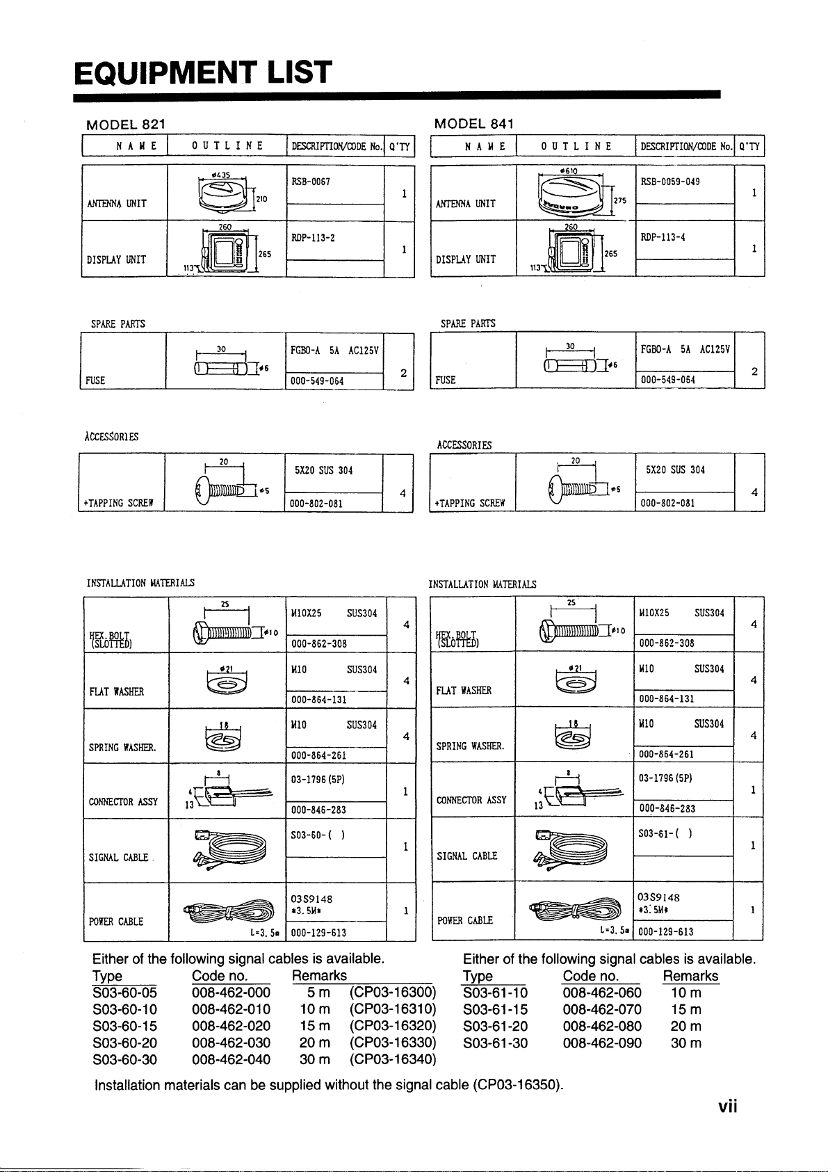
EQUIPMENT LIST ..........................vii
CONFIGURATION .........................viii
1. PRINCIPLE OF OPERATION .......1
1.1 What is Radar?..................................... 1
1.2 How Ships Determined Position Before
Radar .................................................... 1
1.3 How Radar Determines Range ............ 1
1.4 How Radar Determines Bearing.......... 1
1.5 Radar Wave Speed and Antenna Rota-
tion Speed............................................. 1
1.6 The Radar Display ............................... 1
2.26 Watchman ........................................ 18
2.27 Erasing the Heading Marker ............ 19
2.28 Deselecting Ranges.......................... 19
2.29 Displaying Navigation Data During
Stand-by........................................... 19
2.30 Outputting Cursor Position to
Navigator ......................................... 20
2.31 Displaying Cursor Position, Range
and Bearing to Cursor...................... 20
2.32 Visual Alarm Indications ................. 20
3. INTERPRETING THE DISPLAY
3.1 The Radar Wave and Radar Horizon . 21
3.2 Target Properties and Radar Wave
Reflection........................................... 21
3.3 Range Resolution............................... 22
3.4 Bearing Resolution ............................ 22
3.5 False Echoes ...................................... 22
3.6 Nautical Chart and Radar Picture ...... 24
2. OPERATION
2.1 Control Description ............................. 3
2.2 Display Indications and Markers......... 4
2.3 Turning the Radar On and Off............. 4
2.4 Transmitting......................................... 5
2.5 Selecting the Range ............................. 5
2.6 Adjusting LCD Backlighting and
Display Tone........................................ 5
2.7 Adjusting Control Panel Brilliance...... 5
2.8 Adjusting GAIN, STC, A/C RAIN
and FTC ............................................... 6
2.9 Tuning the Receiver............................. 7
2.10 Measuring the Range ......................... 8
2.11 Measuring the Bearing....................... 8
2.12 Menu Operation................................. 9
2.13 Selecting the Display Mode..............11
2.14 The Window Display ....................... 12
2.15 Selecting the Presentation Mode ..... 12
2.16 Guard Alarm .................................... 13
2.17 Suppressing Radar Interference....... 14
2.18 Suppressing Noise Interference ....... 15
2.19 Selecting Pulselength....................... 15
2.20 Off Centering the Display................ 15
2.21 Echo Trails....................................... 16
2.22 The Navigation Data Display .......... 16
2.23 Echo Stretch..................................... 17
2.24 Selecting Unit of Measurement
for Range ......................................... 18
2.25 Selecting Bearing Reference............ 18
4. MAINTENANCE &
TROUBLESHOOTING
4.1 Safety Information............................. 25
4.2 Preventative Maintenance.................. 26
4.3 Replacing the Fuse............................. 26
4.4 Troubleshooting................................. 27
4.5 Self Test ............................................. 28
5. INSTALLATION
5.1 Antenna Unit Installation ................... 29
5.2 Display Unit Installation.................... 36
5.3 Installation Check List....................... 39
5.4 Initial Adjustment of Picture.............. 40
5.5 Displaying the Installation Menus ..... 40
5.6 Entering Initial Settings ..................... 41
5.7 Relative Bearing Alignment .............. 41
5.8 Sweep Timing .................................... 42
5.9 Closing the Installation Menus .......... 42
5.10 Signal cable connection ................... 44
OUTLINE DRAWINGS..................D-1
INTERCONNECTION
DIAGRAMS................................... S-1
SCHEMA TIC DIAGRAMS............. S-3
Declaration of Conformity
i
Page 5

FOREWORD
Congratulations on your choice of the
FURUNO MODEL 821/MODEL 841 Marine Radar. We are confident you will see
why the FURUNO name has become synonymous with quality and reliability.
For over 40 years FURUNO Electric Company has enjoyed an enviable reputation for
innovative and dependable marine electronics equipment. This dedication to excellence
is furthered by our extensive global network
of agents and dealers.
Your radar is designed and constructed to
meet the rigorous demands of the marine environment. However, no machine can perform its intended function unless properly
installed and maintained. Please carefully
read and follow the recommended procedures for installation, operation and maintenance.
While this unit can be installed by the purchaser , any purchaser who has doubts about
his or her technical abilities may wish to
have the unit installed by a FURUNO representative or other qualified technician. The
importance of a thorough installation cannot be overemphasized.
We would appreciate hearing from you, the
end-user, about whether we are achieving
our purposes.
Thank you for considering and purchasing
FURUNO equipment.
Features
Your radar has a large variety of functions,
all contained in a remarkably small cabinet.
The main features of the MODEL 821/
MODEL 841 are:
• Traditional FURUNO reliability and
quality in a compact, lightweight and
low-cost radar.
• Smartly styled, light-weight and compact
radome antenna fits even on small yachts.
• Durable brushless antenna motor.
• High definition 8" LCD raster-scan display.
• On-screen alphanumeric readout of all
operational information.
• Standard features include EBL (Electronic Bearing Line), VRM (Variable
Range Marker), Guard Alarm, Display
Off Center and Echo Trail.
• W atchman feature periodically transmits
the radar to check for radar targets which
may be entering (or exiting) the alarm
zone.
• Operates on 10.2 to 31.2 V DC power
supply and consumes about 40 W.
• Ship’s position in latitude and longitude
(or Loran C T ime Differences), range and
bearing to a waypoint, ship’ s speed, heading and course can be shown in the bottom text area. (Requires a navigation aid
which can output such data in NMEA
0183 format.)
• Zoom feature provided.
ii
Page 6

SPECIFICATIONS–
MODEL 821
10. Bandwidth
7 MHz
11. Duplexer
Circulator with diode limiter
Antenna Unit
1. Radiator
Printed array
2. Radiator length
40 cm
3. Horizontal beamwidth
5.7°
4. Vertical beamwidth
30˚
5. Sidelobe
Less than -20dB
6. Polarization
Horizontal
7. Antenna rotation speed
24 rpm
8. Wind resistance
Relative wind speed 100 kts (51.5 m/s)
Transceiver Module
(contained in radome)
1. Transmitting tube
Magnetron E3587
2. Frequency
9410 MHz ±30MHz, P0N (X band)
3. Peak output power
2 kW
4. Pulselength & pulse repetition rate
0.12µs, 2100 Hz (0.25, 0.5, 0.75 nm)
0.3µs, 1200 Hz (1, 1.5, 2 nm)
0.8µs, 600 Hz (3, 4, 6, 8, 12, 24 nm)
5. Warm-up time
1:30
6. Modulator
FET switching method
7. I. F.
60 MHz
8. Tuning
Automatic or manual
9. Receiver front end
MIC (Microwave IC)
Display Unit
1. Indication system
PPI raster scan
2. Display
8-inch diagonal LCD, STN semitransparent, yellow mode
3. Range scales (nm)
Range, Ring Interval: 0.125(0.0625),
0.25(0.125), 0.5(0.125), 0.75(0.25),
1(0.25), 1.5(0.5), 2(0.5), 3(1), 4(1),
6(2), 8(2), 12(3), 16(4), 24(6)
4. Bearing resolution
6.2˚
5. Bearing accuracy
Better than 1˚
6. Range discrimination
Better than 25 m
7. Range ring accuracy
& discrimination
0.9% or range in use or 8 m,
whichever is larger
8. Minimum range
Better than 37 m
9. Markers
Heading marker, Bearing scale, Range
ring, VRM, EBL, Waypoint (option),
Tuning indicator, Alarm zone, Cursor
10. Alphanumeric indication
Standard: Electronic Bearing Line
(EBL), Echo Stretch (ES), Rain
Clutter Rejection (FTC), Alarm
(G), Interference Rejection (IR),
Stand-by (ST-BY), Echo Trail Time
(TRAIL), Variable Range Marker
(VRM), Range, Range Ring Interval,
Range and Bearing to Cursor (+), Off
Center (OFF CENTER), Watchman
(WATCHMAN)
iii
Page 7

With navigation input (option): Course
(CRS), Latitude and longitude, Speed
(SPD), Range and bearing to waypoint
(WP), Cross Track Error (XTE), Date
and time, Water depth, Water
temperature. (This radar has
only two data input ports. To receive
data from more than two equipment
install an mixing device.)
11. Vibration
Vibration freq. Total amplitude
5 to 12.5 Hz ±1.6 mm
12 to 25 Hz ±0.35 mm
25 to 50 Hz ±0.10 mm
12. Ambient Temperature
Antenna unit: –20˚C to +70˚C
Display unit: 0˚C to +60˚C
Due to the inherent nature of the LCD
its contrast may be affected under
ambient temperature below 0˚C (32˚F)
or above 50˚C (122˚F).
13. Humidity
Relative humidity 95% or less at
+40˚C
14. Waterproofing
Display unit: IEC Pub no. 529 IPX5
Antenna unit: IEC Pub no. 945 class X
15. Power supply &
power consumption
12 V or 24V(10.2 V to 31.2 V DC),
40 W approx.
16. Protection features
Protection against reverse polarity,
overvoltage, overcurrent, and internal
fault
17. Compass safe distance
tinUdradnatS
ssapmoc
yalpsiDm7.0m5.0
annetnAm7.1m4.1
SPECIFICATIONS–
MODEL 841
Antenna Unit
1. Radiator
Printed array
2. Radiator length
54 cm
3. Horizontal beamwidth
4°
4. Vertical beamwidth
25˚
5. Sidelobe
-20 dB within main lobe
-23 dB outside main lobe
6. Polarization
Horizontal
7. Antenna rotation speed
24 rpm
8. Wind resistance
Relative wind speed 100 kts (51.5 m/s)
Transceiver Module
(contained in radome)
1. Transmitting tube
Magnetron MG5248
2. Frequency
9410 MHz ±30MHz, P0N (X band)
3. Peak output power
4 kW
4. Pulselength & pulse repetition rate
0.08µs, 2100 Hz (0.25, 0.5, 0.75 nm)
gnireetS
ssapmoc
0.3µs, 1200 Hz (1, 1.5, 2 nm)
0.8µs, 600 Hz (3, 4, 6, 8, 12, 24, 36
5. Warm-up time
2:30
6. Modulator switching method
FET
7. I. F.
60 MHz
8. Tuning
Automatic or manual
nm)
iv
Page 8

9. Receiver front end
MIC (Michoeave IC)
10. Bandwidth
7 MHz
11. Duplexer
Circulator with diode limiter
Display Unit
1. Indication system
PPI raster scan
2. Display
8-inch diagonal LCD, STN semitransparent, yellow mode
3. Range scales (nm)
Range, Ring Interval: 0.125(0.0625),
0.25(0.125), 0.5(0.125), 0.75(0.25),
1(0.25), 1.5(0.5), 2(0.5), 3(1), 4(1),
6(2), 8(2), 12(3), 16(4), 24(6),
4. Bearing resolution
6.2˚
5. Bearing accuracy
Better than 1˚
6. Range discrimination
Better than 25 m
7. Range ring accuracy
& discrimination
0.9% or range in use or 8 m,
whichever is larger
8. Minimum range
Better than 37 m
9. Markers
Heading marker, Bearing scale, Range
ring, VRM, EBL, Waypoint (option),
Tuning indicator, Alarm zone, Cursor
10. Alphanumeric indication
Standard: Electronic Bearing Line
(EBL), Echo Stretch (ES), Rain
Clutter Rejection (FTC), Alarm
(G), Interference Rejection (IR),
Stand-by (ST-BY), Echo Trail Time
(TRAIL), Variable Range Marker
(VRM), Range, Range Ring Interval,
Range and Bearing to Cursor (+), Off
Center (OFF CENTER), Watchman
(WATCHMAN)
36 (6)
With navigation input (option): Course
(CRS), Latitude and longitude, Speed
(SPD), Range and bearing to waypoint
(WP), Cross Track Error (XTE), Date
and time, Water depth, Water
temperature. (This radar has only two
data input ports. To receive data from
more than two equipment install an
mixing device.)
11. Vibration
Vibration freq. Total amplitude
5 to 12.5 Hz ±1.6 mm
12 to 25 Hz ±0.35 mm
25 to 50 Hz ±0.10 mm
12. Ambiont temperature
Antenna unit: –20˚C to +70˚C
Display unit: 0˚C to +60˚C
Due to the inherent nature of the LCD
its contrast may be affected under
ambient temperature below 0˚C (32˚F)
or above 50˚C (122˚F).
13. Humidity
Relative humidity 95% or less at
+40˚C
14. Waterproofing
Display unit: IEC Pub no. 529 IPX5
Antenna unit: IEC Pub no. 945 class X
15. Power supply &
power consumption
12 V or 24V(10.2 V to 31.2 V DC),
40 W approx.
16. Protection features
Protection against reverse polarity,
overvoltage, overcurrent, and internal
fault
tinUdradnatS
ssapmoc
yalpsiDm7.0m5.0
annetnAm4.1m1.1
gnireetS
ssapmoc
v
Page 9

17. Compass safe distance
Interface NMEA
(MODEL 821/841)
Input
Own ship’s position : RMA>RMC>GLL
(GLL is available Ver.5 and after.)
Speed : RMA>RMC>VTG>VHW
Heading(True):
HDT>VHW>HDG>VHW>HDM
Heading (Magnetic):
HDM>VHW>HDG>VHW>HDM
Course (True):
RMA>RMC>VTG
Course (Magnetic)
VTG>RMA>RMC
Waypoint (L/L, Range, Bearing):
RMB>BWC>BWR
Loran time difference :
RMA>GLC>GTD
Water depth : DPT>DBK, DBS, DBT
Water temperature : MDA>MTW
Time : ZDA
XTE : RMB>XTE>APB
Output
TLL : On using “HM OFF” key.
RSD : A cycle of four seconds
vi
Page 10
Page 11
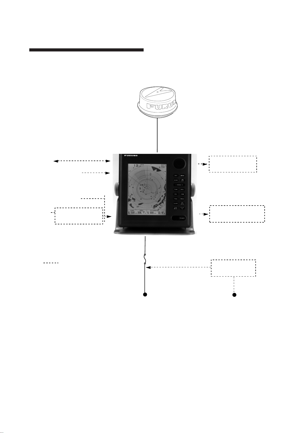
CONFIGURATION OF MODEL 821/841
MODEL 821/841
Antenna Unit
(MODEL 821)
NAV
Video Sounder
Fluxgate Heading
Sensor C-2000
Gyro
*Equivalent to NMEA0183
IEC 1162*
IEC 1162*
Gyro Converter
AD-100
Option
(In/Out)
(In)
5A
10.2~31.2VDC
Remote Display
FMD-811
External Alarm
Buzzer OP03-136
Rectifier
RP-62
115/230VAC
viii
Page 12

1. PRINCIPLE OF OPERATION
1.1 What is Radar?
The term "RADAR" is an acronym meaning RAdio Detection And Ranging. Although the basic principles of radar were
developed during World War II, primarily
by scientists in Great Britain and the United
States, the use of echoes as an aid to navigation is not a new development.
1.2 How Ships Determined Position Before Radar
Before the invention of radar, when running
in fog near a rugged shoreline, ships would
sound a short blast on their whistles, fire a
shot, or strike a bell. The time between the
origination of the sound and the returning
of the echo indicated how far the ship was
from the cliffs or the shore. The direction
from which the echo was heard indicated
the relative bearing of the shore.
1.4 How Radar Determines Bearing
The bearing to a target found by the radar is
determined by the direction in which the
radar scanner antenna is pointing when it
emits an electronic pulse and then receives
a returning echo. Each time the scanner rotates pulses are transmitted in the full 360
degree circle, each pulse at a slightly different bearing from the previous one. Therefore, if one knows the direction in which the
signal is sent out, one knows the direction
from which the echo must return.
1.5 Radar Wave Speed and Antenna Rotation Speed
Note that the speed of the radar waves out
to the target and back again as echoes is extremely fast compared to the speed of rotation of the antenna. By the time radar echoes
have returned to the scanner, the amount of
scanner rotation after initial transmission of
the radar pulse is extremely small.
1.6 The Radar Display
1.3 How Radar Determines Range
Radar determines the distance to the target
by calculating the time difference between
the transmission of a radar signal and the
reception of the reflected echo. It is a known
fact that radar waves travel at a nearly constant speed of 162,000 nautical miles per
second. Therefore the time required for a
transmitted signal to travel to the target and
return as an echo to the source is a measure
of the distance to the target. Note that the
echo makes a complete round trip, but only
half the time of travel is needed to determine the one-way distance to the target. This
radar automatically takes this into account
in making the range calculation.
The range and bearing of a target is displayed
on what is called a Plan Position Indicator
(PPI). This display is essentially a polar diagram, with the transmitting ship’s position
at the center. Images of target echoes are
received and displayed at their relative bearings, and at their distance from the PPI center.
With a continuous display of the images of
targets, the motion of the transmitting ship
is also displayed.
1
Page 13
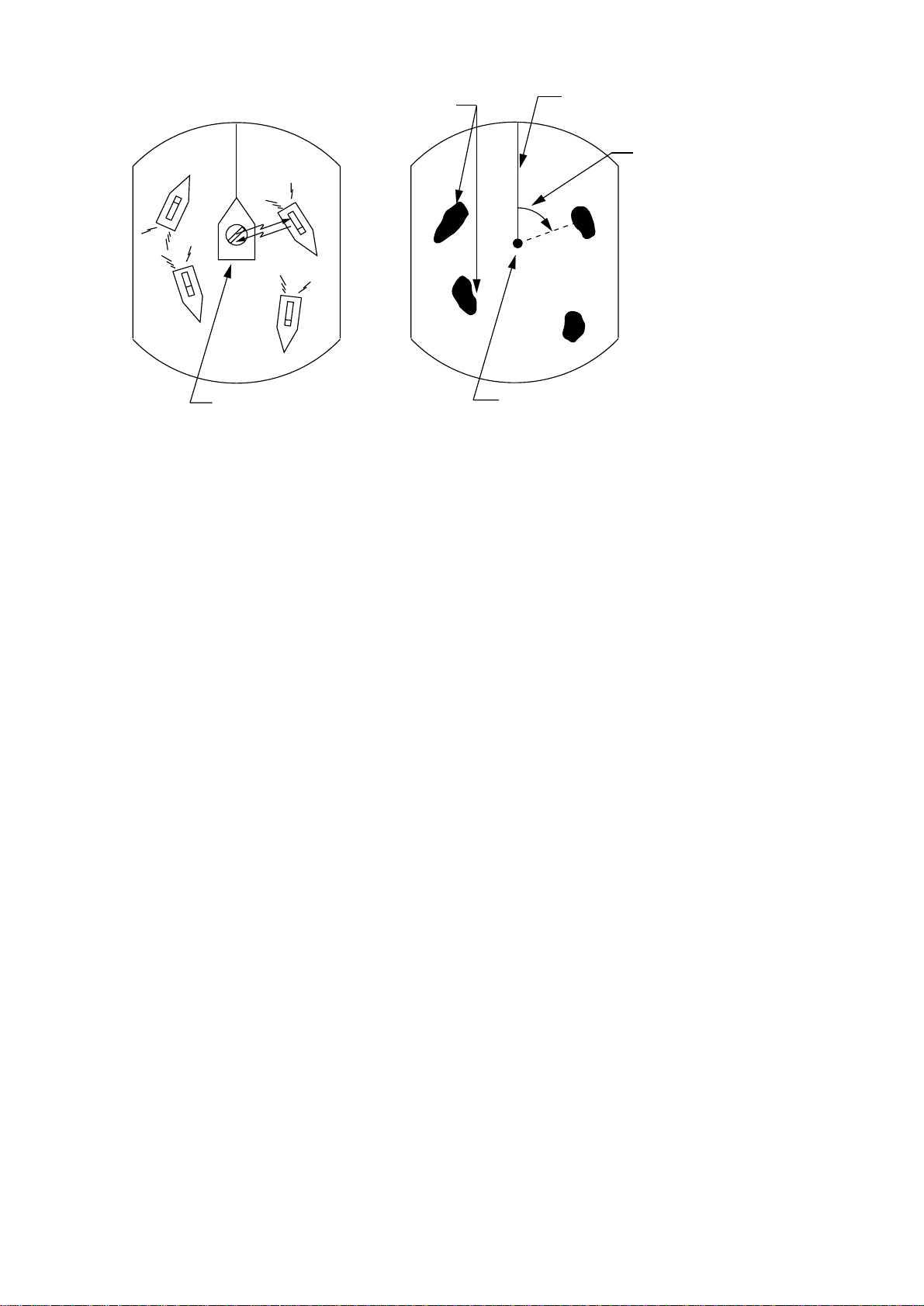
Targets
Heading marker
Range and bearing
of a target, relative
A
D
A
to own ship, are
D
readable on the PPI.
B
C
Own ship
(radar)
(A) Bird's eye view of situation
B
C
Own ship
in center
(B) Radar picture of (A)
Figure 1-1 How radar works
2
Page 14
2. OPERATION
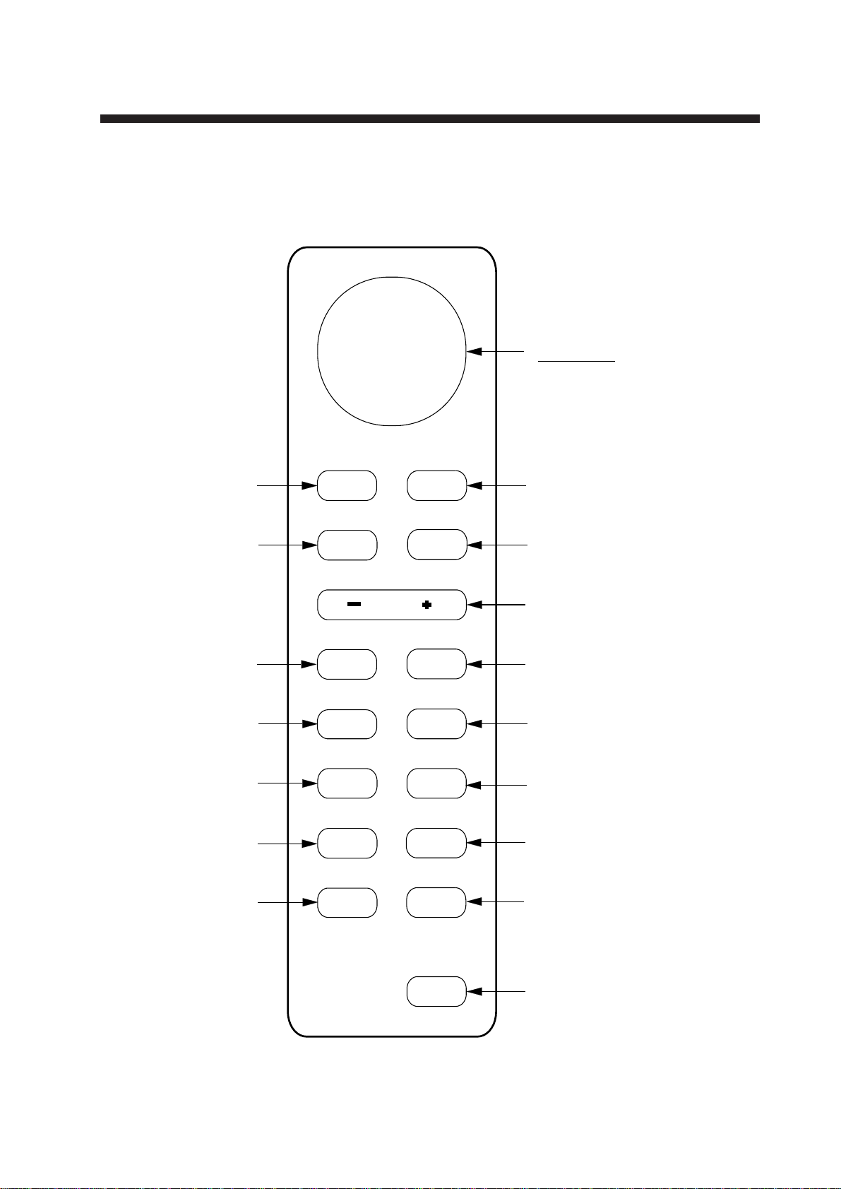
2.1 Control Description
Cursor pad
Shift cursor, VRM
and EBL; select
items and options
on menu.
Registers selection
on menus.
Press to adjust gain,
A/C RAIN, STC
and FTC.
Adjusts display
tone.
Turns the EBL
on/off.
Plots targets' trails.
Sets guard
zone area.
ENT MENU
ECHO
RANGE
TONE BRILL
EBL
TRAIL
GUARD
HM
OFF
VRM
RINGS
OFF
CENTER
Opens/closes menus.
Erases heading marker;
selects cursor data (Lat/Long, R/B);
outputs cursor position.
Selects radar range.
Adjusts display brilliance.
Turns the VRM on/off.
Turns the range
rings on/off.
Off centers
the display.
Selects display mode;
erases heading error
indication.
DISP
MODE
ST-BY
TX
POWER
Figure 2-1 Control panel
Sets radar in stand-by;
transmits radar pulse.
Turns power on/off.
3
Page 15
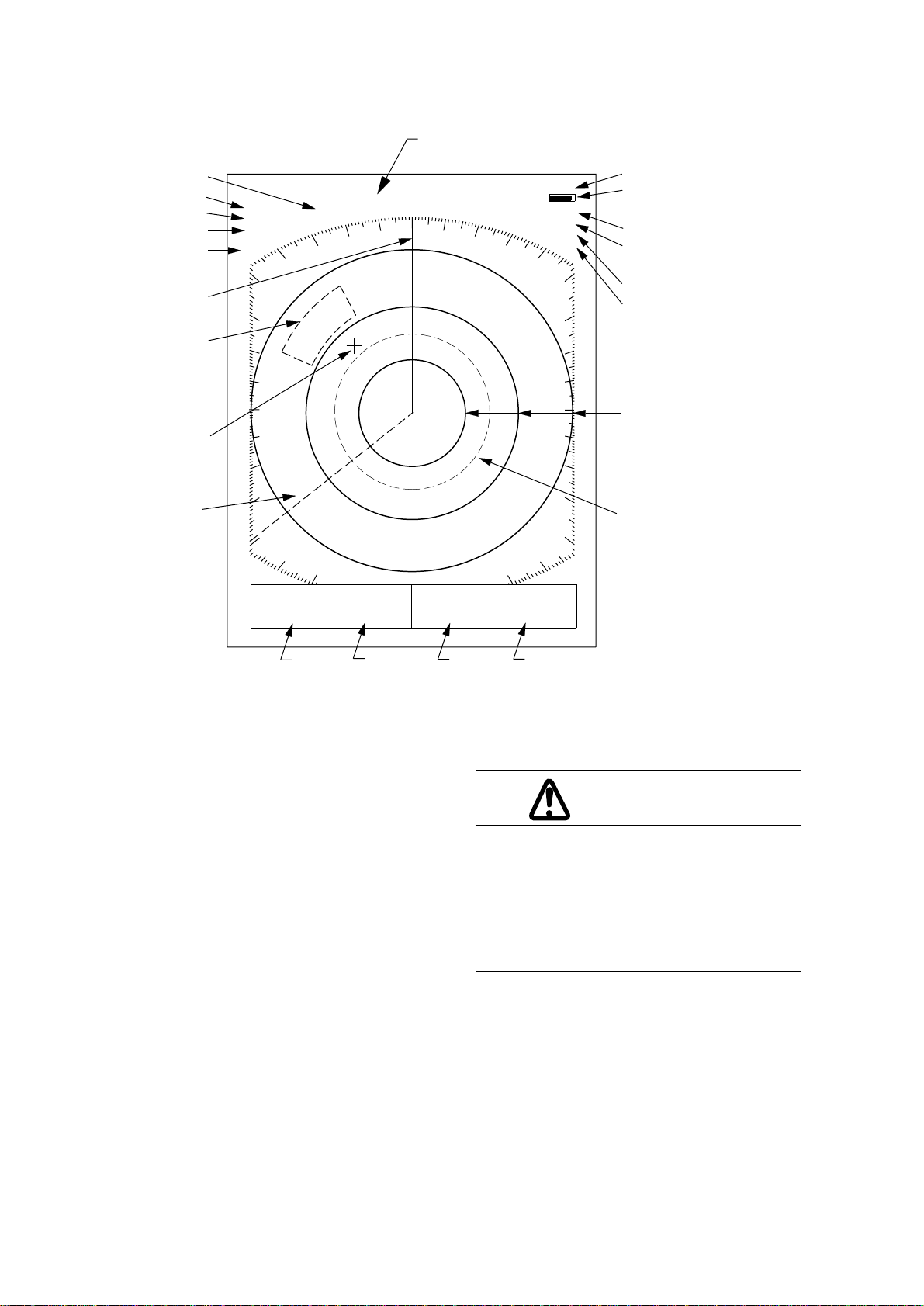
2.2 Display Indications and Markers
Heading (requires
Range
Range ring interval
Presentation mode
Off center
Pulsewidth
Heading marker
Guard zone
area
Cursor
0.5
CU
OFF
CENTER
SP
1.5
HDG 326.8°
NM
heading data)
TRAIL AUTO
0:00
15S
G (IN)
FTC1
ES
Echo trail, AUTO tuning
Echo trail elapsed time,
echo trail time, tuning indicator
Guard zone
IR
Fast Time Constant
(rain clutter suppressor)
Echo stretch
Interference rejector
Range ring
EBL
VRM EBL + CURSOR
0.675
NM
220.9°
VRM
range
R
0.646NM 308.7°
EBL
bearing
Figure 2-2 Display indications
2.3 Turning the Radar On and Off
Turning the radar on
Press the [POWER] key to turn the radar on
or off. The control panel lights and a timer
displays the time remaining for warm up of
the magnetron (the device which produces
radar pulses), counting down from 2:30
(MODEL 841) or 1:30 (MODEL 821) to
0:01.
Note: When the power is reapplied within a
certain amount of time and circuits remain
charged, the warmup process is skipped—you
can transmit immediately.
VRM
Range and bearing to cursor
or cursor position in latitude
and longitude may be displayed
}
by pressing the [HM OFF] key.
Cursor
range
R
Cursor
bearing
CAUTION
The radar antenna emits high frequency
radio radiation which can be harmful,
particularly to your eyes. Never look
directly at the antenna from a distance of
less than two feet when the radar is in
operation. Always make sure no one is near
the antenna before turning on the radar.
Note: When the heading signal is lost, the HDG
readout at the top of the screen shows ***.*.
This warning stays on when the heading signal is restored to warn the operator that the
readout may be unrealiable. The warning may
be erased by pressing the [DISP MODE] key,
4
Page 16
2.4 Transmitting
After the power is turned on and the magnetron has warmed up, ST-BY (Stand-By)
appears at the screen center . This means the
radar is now fully operational. In stand-by
the radar is available for use at anytime—
but no radar waves are being transmitted.
2.6 Adjusting LCD Backlighting and Display Tone
The [BRILL] key adjusts the LCD backlighting in eight levels, including off. The
[TONE] key adjusts the tone (contrast) of
the display in 32 levels, including off.
Press the [ST -BY TX] key to transmit. When
transmitting, any echoes from targets appear
on the display . This radar displays echoes in
four tones of gray according to echo strength.
When you won’t be using the radar for an
extended period but want to keep it in a state
of readiness, press the [ST-BY TX] key to
set the radar in stand-by.
2.5 Selecting the Range
The range selected automatically determines
the range ring interval, the number of range
rings, pulselength and pulse repetition rate,
for optimal detection capability in short to
long ranges.
Procedure
Procedure
1) Press the [BRILL] key (or [TONE] key).
The display shown in Figure 2-3 appears.
BRILL
UP
Tone
setting
TONE
DOWN
BRILL
DOWN
19 7
<MENU TO EXIT>
TONE
UP
Item selected
for adjustment
LCD brilliance
setting
Figure 2-3 Display for adjustment of
brilliance and tone
2) Press the [BRILL] key (or [TONE] key)
to set level. For fine adjustment, press
cursor pad at 12o'clock/6 o'clock for brilliance and 3o'clock/9o'clock for tone.
Press the [– RANGE +] key . The range and
range ring interval appear at the top left corner on the display.
Tips for selecting the range
• When navigating in or around crowded
harbors, select a short range to watch for
possible collision situations.
• If you select a lower range while on open
water , increase the range occasionally to
watch for vessels that may be heading
your way.
2.7 Adjusting Control Panel Brilliance
Procedure
1) Press the [MENU] key.
2) Press the cursor pad to select Backlight/
Brilliance and press the [ENT] key.
3) Press the cursor pad to select Panel.
4) Press the cursor pad to select brilliance
level; 4 is the highest.
5) Press the [ENT] key followed by the
[MENU] key.
5
Page 17
2.8 Adjusting GAIN, STC, A/C RAIN and FTC
General procedure
The [ECHO] key enables adjustment of the
gain, STC, A/C RAIN and FTC.
1) Press the [ECHO] key . The following display appears.
AUTO 1 2 3
[
GAIN
STC
A/C RAIN 00
FTC 0 1 2
◆
◆
[
MAN
AUTO 1 2 3
MAN
12
ECHO KEY
TO EXIT
Figure 2-4 Display for adjustment of
GAIN, STC, A/C RAIN and FTC
2) Press the cursor pad to select item to adjust. Current selection is circumscribed
by dashed rectangle.
3) Press [ENT].
3) Press the cursor pad to set level.
Item selected
for adjustment
Current
level
How to adjust STC (suppressing sea
clutter)
Echoes from waves can be troublesome,
covering the central part of the display with
random signals known as sea clutter. The
higher the waves, and the higher the scanner above the water, the further the clutter
will extend. Sea clutter appears on the display as many small echoes which might affect radar performance. (See the left-hand
figure in Figure 2-5).
The STC reduces the amplification of echoes at short ranges (where clutter is the greatest) and progressively increases
amplification as the range increases, so amplification will be normal at those ranges
where there is no sea clutter. The control is
effective up to about 4 miles.
STC can be adjusted automatically or manually . For manual adjustment, first adjust the
gain and then transmit on short range. Adjust the STC level such that the clutter is
broken up into small dots, and small targets
become distinguishable. If the setting is set
too low, tar gets will be hidden in the clutter ,
while if it is set too high, both sea clutter
and targets will disappear from the display.
In most cases adjust so clutter has disappeared to leeward, but a little is still visible
windward.
4) Press the [ECHO] key to finish.
How to adjust the gain (sensitivity)
The gain works in precisely the same manner as the volume control of a broadcast receiver, amplifying the signals received.
You can adjust the gain automatically or
manually . For manual adjustment, adjust the
sensitivity on the highest range—the background noise is clearer on that range. The
proper setting is such that the background
noise is just visible on the screen. If you set
up for too little gain, weak echoes may be
missed. On the contrary excessive gain
yields too much background noise; strong
targets may be missed because of the poor
contrast between desired echoes and the
background noise on the display.
6
If there is no clutter visible on the display,
turn off the circuit.
Sea clutter at
display center
STC adjusted;
sea clutter suppressed.
Figure 2-5 Effect of STC
Page 18
How to adjust A/C RAIN and FTC
1.5
NM
0.5
AUTO
Tuning
indicator
(suppressing rain clutter)
The vertical beamwidth of the scanner is designed to see surface targets even when the
ship is rolling. However, by this design the
unit will also detect rain clutter (rain, snow,
hail, etc.) in the same manner as normal targets. Figure 2-6 shows the appearance of rain
clutter on the display.
Adjusting A/C RAIN
When rain clutter masks echoes over a wide
range, raise the A/C RAIN slightly to distinguish targets from the clutter.
2.9 Tuning the Receiver
The receiver can be tuned automatically or
manually . For automatic tuning the receiver
is tuned each time you switch from standby to transmit. For manual tuning, the receiver is properly tuned when the longest
tuning indicator appears. (However, the
length of the indicator changes with the number of radar echoes, range and other factors.)
Figure 2-7 Tuning indicator
Appearance of
rain clutter
A/C RAIN adjusted;
rain clutter suppressed.
Figure 2-6 Effect of A/C RAIN
Adjusting FTC
To suppress rain clutter from heavy storms
or scattered rain clutter , adjust the FTC. The
FTC circuit splits up these unwanted echoes into a speckled pattern, making recognition of solid targets easier. FTC and
selected level appear at the top right-hand
corner of the display when the circuit is
turned on.
Note: In addition to reducing clutter, the FTC
can be used in fine weather to clarify the picture when navigating in confined waters. However, with the circuit activated the receiver is
less sensitive. Therefore, turn off the circuit
when its function is not required.
Manual tuning
The default tuning method is automatic. To
switch to manual tuning;
1) Press the [MENU] key to open the menu.
2) Press the cursor pad to select Tuning.
3) Press the cursor pad to select MANUAL.
4) Press the [ENT] key followed by the
[MENU] key.
How to tune manually
While pressing and holding down the [HM
OFF] key, press the 9 o'clock or 3o'clock
position on the cursor pad to tune. Tune to
show the longest tuning indicator.
7
Page 19
2.10 Measuring the Range
You can measure the range to a target three
ways: by the range rings, by the cursor , and
by the VRM (Variable Range Marker).
By range rings
Press the [RINGS] key to display the range
rings. Count the number of rings between
the center of the display and the target.
Check the range ring interval (at the top left
corner) and judge the distance of the echo
from the inner edge of the nearest ring.
By cursor
Operate the cursor pad to place the cursor
intersection on the inside edge of the target
echo. The range to the tar get, as well as the
bearing, appears at the bottom of the display.
Target
VRM
range
VRM
1.5
0.5
NM
VRM EBL + CURSOR
0.675
NM
220.9°
R
0.675NM 308.7°
Figure 2-8 Measuring range by the VRM
2.11 Measuring the Bearing
R
By VRM
1) Press the [VRM] key to display the VRM.
2)
Press the cursor pad to place the VRM
on the inside edge of the target. (The cursor appears and is linked with the VRM,
allowing you to measure both range and
bearing to the target.)
3) Check the VRM readout at the bottom
left-hand corner of the display to find the
range to the target.
Note: The VRM is automatically anchored
when no cursor pad key is operated within
about 10 seconds.
To erase the VRM, press and hold down
the [VRM] key for about three seconds.
There are two ways to measure the bearing
to a target: by the cursor, and by the EBL
(Electronic Bearing Line).
By cursor
Operate the cursor pad to bisect the target
with the cursor intersection. The bearing to
the target appears at the bottom right-hand
corner of the display.
By EBL
1) Press the [EBL] key to display the EBL.
2) Press the cursor pad to bisect the target
with the EBL. (The cursor appears and is
linked with the EBL, allowing you to
measure both bearing and range to the
target.)
3) Check the EBL readout at the bottom lefthand corner of the display to find the bearing to the tar get.
8
Note: The EBL is automatically anchored when
no cursor pad key is operated within about 10
seconds.
Page 20
T o erase the EBL, press and hold down the
[EBL] key for about three seconds.
Target
EBL
1.5
0.5
0.675
NM
VRM EBL + CURSOR
NM
300.1°
R
0.675NM 300.1°R
EBL
bearing
Figure 2-9 Measuring bearing by the EBL
2.12 Menu Operation
The menu, consisting of 6 sub menus, mostly
contains less-often used functions which
once preset do not require regular adjustment. To open or close the menu, press the
[MENU] key. You can select items on the
menu with the cursor pad.
Basic menu operation
1) Press the [MENU] key to open the menu.
The main menu appears.
● MAIN MENU ●
Select item by ▲▼ keys
and press ENT key.
1. Backlight/Brilliance
2. P/L, IR, NR & Radar Mode
3. Nav Data
4. Mode & Function
5. Tuning AUTO MANUAL
6. Self Check
7. Installation Setup 1
Tips for measuring the bearing
• Bearing measurements of smaller targets
are more accurate; the center of larger target echoes is not as easily identified.
• Bearings of stationary or slower moving
targets are more accurate than bearings
of faster moving targets.
• To minimize bearing errors keep echoes
in the outer half of the picture by changing the range scale; angular difference becomes difficult to resolve as a target
approaches the center of the display.
Target on collision course with your
vessel?
You can determine if a target might be
on a collision course with your vessel by
placing the EBL on the target. If it tracks
along the EBL as it approaches the
screen center it may be on a collision
course with your vessel.
. . . . . . . . . . . . . . . . .
Press HM-OFF to temporarily
hide menu.
<Press MENU key to escape.>
Figure 2-10 Main menu
2) Press the cursor pad to select menu and
press the [ENT] key.
3) Press the cursor pad to select menu item.
4) Press the cursor pad to select option.
5) Press the [ENT] key to register selection.
6) Press the [MENU] key to close the menu.
Menu description
See the table on the next page.
9
Page 21

Table 1-1 Menu description
Menu
1. BACKLIGHT/BRILLIANCE MENU
Select item and option
by ▲▼ keys.
1. Panel
2. Echo Trails
. . . . . . . . . . . . . . . . . . . . . . . . . . . . . . . . . . . .
Press HM-OFF to temporarily
hide menu.
<Press MENU for main menu.>
2. P/L, IR, NR & Radar Mode
Select item and option
by ▲▼ keys.
1. Pulselength
2. Int Reject
3. Noise Reject
4. Echo Stretch
5. Radar mode
. . . . . . . . . . . . . . . . . . . . . . . . . . . . . . . . . . . .
Press HM-OFF to temporarily
hide menu.
<Press MENU for main menu.>
1 2 3 4
1 2
SHORT LONG
OFF 1 2 3
OFF ON
OFF ON
CU WPT-UP
Function
1. Selects control panel backlighting; four is
maximum backlighting.
2. Selects brilliance for echo trails and
markers; four is maximum brilliance.
1. Selects pulselength for 1.5 and 3 mile
ranges.
2. Selects radar interference rejector level; 3
provides highest degree of rejection.
3. Turns noise rejector on/off.
4. Turns echo stretch on/off.
5. Select mode for CU or WPT-UP.
3. NAV DATA MENU
Select item and option
by ▲▼ keys.
1. Navigator
2. Nav Data Disp
3. Pos Disp Mode
4. Depth Unit
5. Temp Unit
6. STBY Display
. . . . . . . . . . . . . . . . . . . . . . . . . . . . . . . . . . . .
Press HM-OFF to temporarily
hide menu.
<Press MENU for main menu.>
4. MODE & FUNCTION MENU
Select item and option
by ▲▼ keys.
1. Window Display
2. Watchman
3. Alarm Mode
4. VRM Unit
5. EBL Ref
6. Range
. . . . . . . . . . . . . . . . . . . . . . . . . . . . . . . . . . .
Press HM-OFF to temporarily
hide menu.
ALL GPS LC
OFF ON
L/L TD
M FA FT
°C °F
NORM NAV
ZOOM WIDE
OFF 5' 10' 20'
IN OUT
NM KM SM
REL TRUE
1/8 1/4 1/2 3/4 1 1/5
2 3 4 8 12 16 24 *36
1. Selects navigator among GPS, Loran and
all navigators available. In the "All" setting
the radar selects a navigator in order of
navigator accuracy–GPS, Loran and other.
2. Turns navigation data display on/off.
3. Selects position display format; latitude and
longitude or Loran TDs.
4. Selects unit of measurement for depth;
meters, feet or fathoms.
5. Selects unit of measurement for water
temperature; °C or °F.
6. Selects what to display during stand-by;
navigation data (requires navigation input)
or "STBY".
1. Selects window display format; zoom or
wide.
2. Selects watchman interval among 5 min, 10
min or 20 min.
3. Selects alarm mode; IN (alarm to targets
entering the guard zone, or OUT (alarm to
targets exiting the guard zone.
4. Selects VRM unit; nm, km or sm.
5. Selects EBL reference; relative or true.
6. Selects ranges to use. Select range to
enable (disable) and press [ENT] key.
* Model 841 only
<Press MENU for main menu.>
Tuning Selects AUTOMATIC or MANUAL tuning.
Self Check Checks the radar system for proper operation.
* Default settings shown in boldface.
10
Page 22

2.13 Selecting the Display Mode
The display mode may be selected with the
[DISP MODE] key. Four modes are available (with navigation input): Normal, Normal + Window, Normal + Nav Data, and
Normal + Window + Nav Data.
Each time the key is pressed the display
mode changes in one of the sequences shown
below, depending on equipment connected
and menu settings.
Note: In the window display mode, the [DISP
MODE] key reselects zoom area. T o select the
display mode while in the window display
mode, press the key twice.
Window Display
Nav Display
VRM EBL +CURSOR
**.** NM ***.*°R ***.**NM ***.*° R
Window Display
Nav Display
WIDE / ZOOM
ON / OFF
WIDE / ZOOM
ON / OFF
ZOOM
VRM EBL +CURSOR
**.** NM ***.*°R ***.**NM ***.*° R
VRM EBL +CURSOR
**.** NM ***.*°R ***.**NM ***.*° R
Figure 2-11 Display modes
ZOOM
VRM EBL +CURSOR
**.** NM ***.*°R ***.**NM ***.*° R
11
Page 23

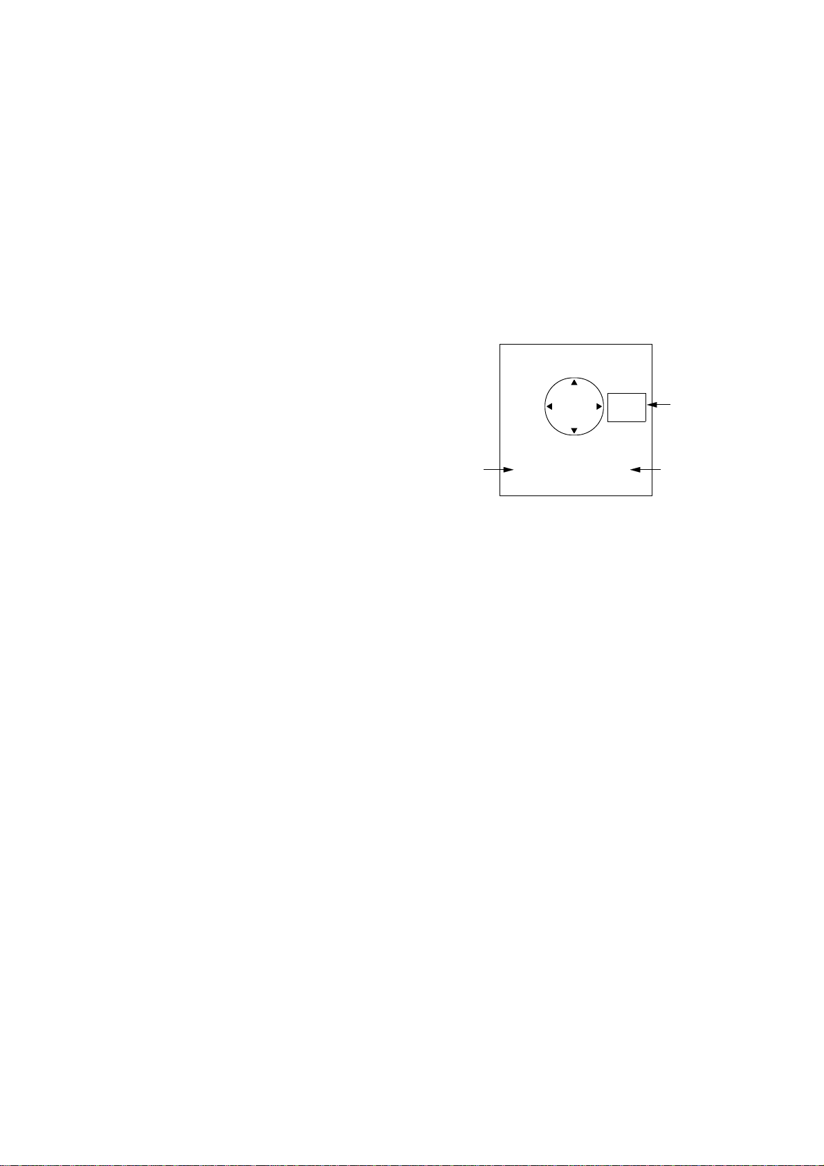
2.14 The Window Display
The window display appears at the bottom
right (or left) 1/4 of the display. Two types
of window displays are available: zoom and
wide. Zoom doubles the size of the area selected by the operator, and wide (range-up)
compresses and displays the entire radar picture on the next higher range.
Note: The zoom display does not function on
the 0.125 and 0.25 nm ranges.
Area selector (1/4 or 1/3 of range)
Window
display
area
VRM EBL +CURSOR
**.** NM ***.*°R ***.**NM ***.*° R
(1) Press [DISP MODE]
to select the window
display.
VRM EBL +CURSOR
**.** NM ***.*°R ***.**NM ***.*° R
(2) Press cursor keys
to select area to zoom
and press [ENT].
Selecting the type of window display
1) Press the [MENU] key.
2) Select Mode & Function and press the
[ENT] key .
Note: When you place the circle cursor
behind the window display, the window
display shifts left (or right) so you may view
the circle cursor.
3) Select Window Display to Zoom or W ide
(range-up).
4) Press the [ENT] key followed by the
[MENU] key .
Selecting the area for the zoom picture
1) Press the [DISP MODE] key to select the
window display. The area selector is a
solid circle.
2) Press the cursor pad to place the circle
cursor (area selector) on the area to zoom.
Figure 2-12 How to select
the area to zoom
2.15 Selecting the Presentation Mode
This radar provides four presentation modes:
head-up, course-up (course-up or waypointup; selectable on menu), north-up and true
motion. Press the [DISP MODE] and [HM
OFF] keys together to select a presentation
mode. Each time the keys are pressed, if
heading signal is input to the radar, the presentation mode and mode indication change
in the sequence of HU, CU (or WU), NU,
TM. If there is no heading signal input to
the radar, the presentation mode is always
HU.
CU
HU
(head-up)
(couse-up)
WU
(waypoint-up)
NU
(north-up)
TM
(true motion)
3) Press the [ENT] key. The area selector
becomes a dashed circle and the cursor
can be moved indepedently.
To reselect area to zoom, press [ENT] or
[DISP MODE] and follow steps 2 and 3.
12
Selecting course-up mode for CU or
WPT-UP
In course-up, you may select CU or WPTUP, on the menu.
CU (course-up)
An azimuth stabilized display in which the
line connecting the center with the top of
the display indicates own ship’s intended
course.
Page 24

WPT-UP (waypoint-up)
Selecting guard zone type
An azimuth stabilized display in which the
line connecting the center with the top of
the display indicates the bearing to the “TO”
waypoint, which is selected on the navigational equipment connected to the radar.
When navigating a route and own ship enters the arrival zone of a waypoint, the radar displays the bearing to the next “TO”
waypoint.
Procedure
1. Press the [MENU] key to open the menu.
2. Press the cursor pad to select 2. P/L, IR,
NR & Radar Mode.
3. Press the cursor pad to select Radar mode.
4. Select option for CU or WPT-UP.
5. Press the [ENT] key followed by the
[MENU] key.
The guard alarm can be set to sound on targets entering (guard in) or exiting (guard out)
the guard zone. Select type of guard zone
as follows.
1) Press the [MENU] key to display the
menu.
2) Select Mode & Function and press the
[ENT] key.
3) Select Alarm Mode to IN or OUT.
4) Press the [ENT] key followed by the
[MENU] key.
Dashed line:
no alarm
Guard
zone
NOTE:
Insert display example and description for each
presentation mode, like in FR-1500M2 or FR8000 series’. Also, add section on how display
is reset in true motion and change Table of
Contents if necessary.
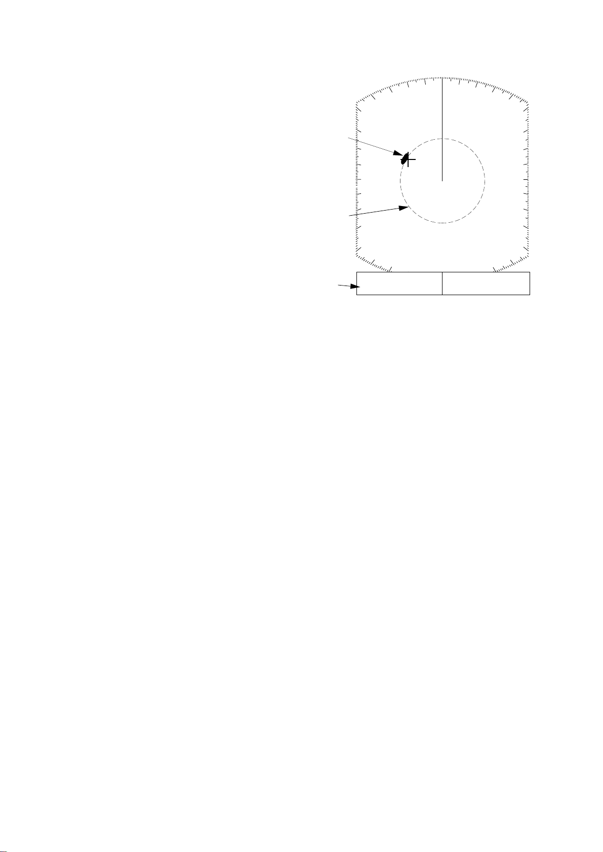
2.16 Guard Alarm
The guard alarm allows the operator to set
the desired range and bearing for a guard
zone. When ships, islands, landmasses, etc.
enter (or exit, depending on type of guard
zone in use.) the guard zone an audible alarm
sounds to call the operator ’s attention. The
alarm is very effective as an anticollision
aid when using an autopilot or navigating
in narrow channels.
CAUTION
IN ALARM OUT ALARM
Figure 2-13 In and out alarms
Setting the guard zone
1) Mentally create the guard zone you want
to display. See Figure 2-14 (1).
2) Operate the cursor pad to set cursor on
top (bottom) left edge of the guard zone.
Press the [GUARD] key. *G (IN) (or G
OUT)), with asterisk blinking, appears at
the top right-hand corner on the display.
(The asterisk indicates the guard zone is
partially set.) See Figure 2-14 (2).
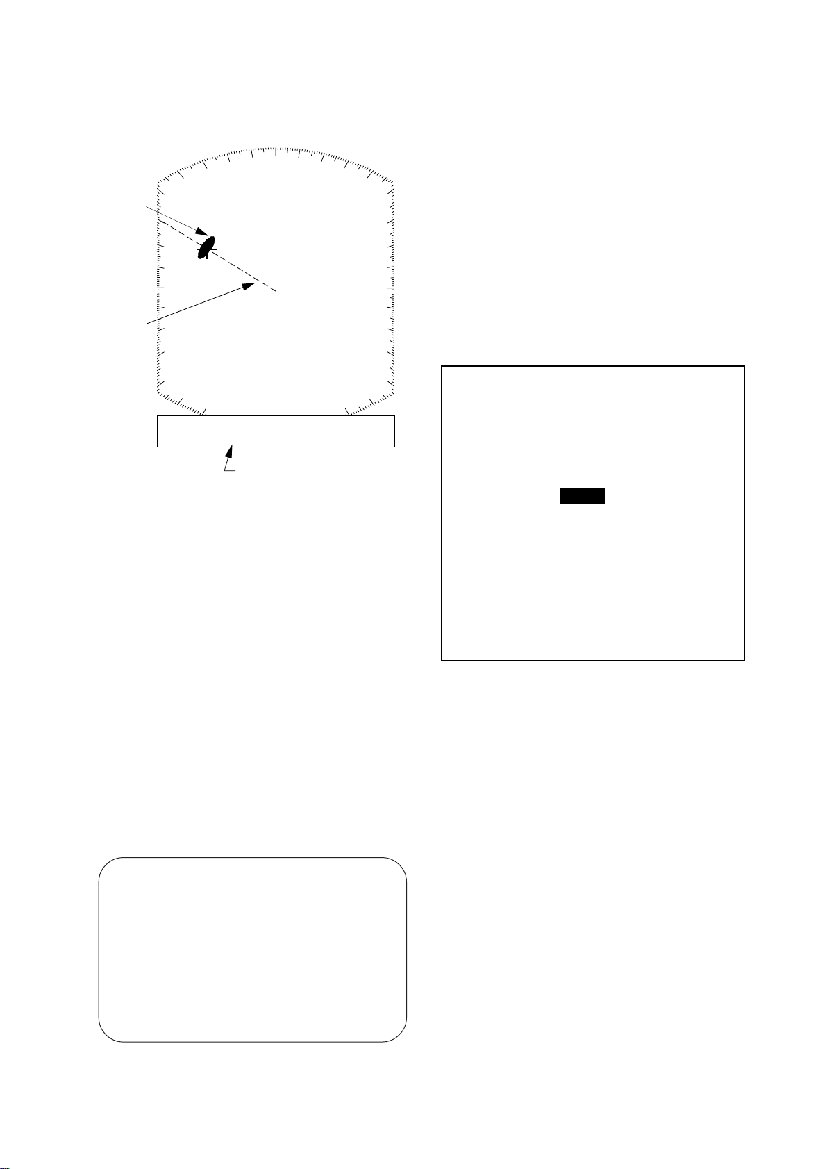
3) Operate the cursor pad to set cursor on
bottom (top) right edge of the guard zone
and press the [GUARD] key. The asterisk disappears. See Figure 2-14 (3).
4) Guard zone appears on the display. See
Figure 2-14 (4).
The guard alarm is a useful anti-collision aid, but
does not relieve the operator of the responsibility
to also keep a visual lookout for possible
collision situations. The alarm should never be
used as the sole means for detecting possible
collision situations.
Silencing the audible alarm
Any ships, landmasses, etc. coming into (or
going out of) the guard zone will trigger the
audible alarm and display the guard zone in
13
Page 25

reverse video. You can silence the alarm by
pressing the [GUARD] key. When this is
done, G (ACKN) replaces G (IN) (or G
(OUT)).
Press the [GUARD] key again to reactivate
the alarm. G (IN) (or G (OUT)) replaces G
(ACKN).
Canceling the guard zone
Press and hold down the [GUARD] key until
the guard zone disappears.
Notes on the guard alarm
• When the radar range is less than one half
of the guard zone range, the guard zone
disappears from the display and UP
RANGE appears. If this happens, raise
the range to redisplay the guard zone.
• A target echo does not always mean a
landmass, reef, ships or surface objects
but can imply returns from sea surface or
Asterisk blinking
precipitation. As the level of these returns
varies with environment, the operator
should properly adjust the STC, gain (sensitivity), A/C RAIN and FTC to be sure
the alarm system does not overlook target echoes.
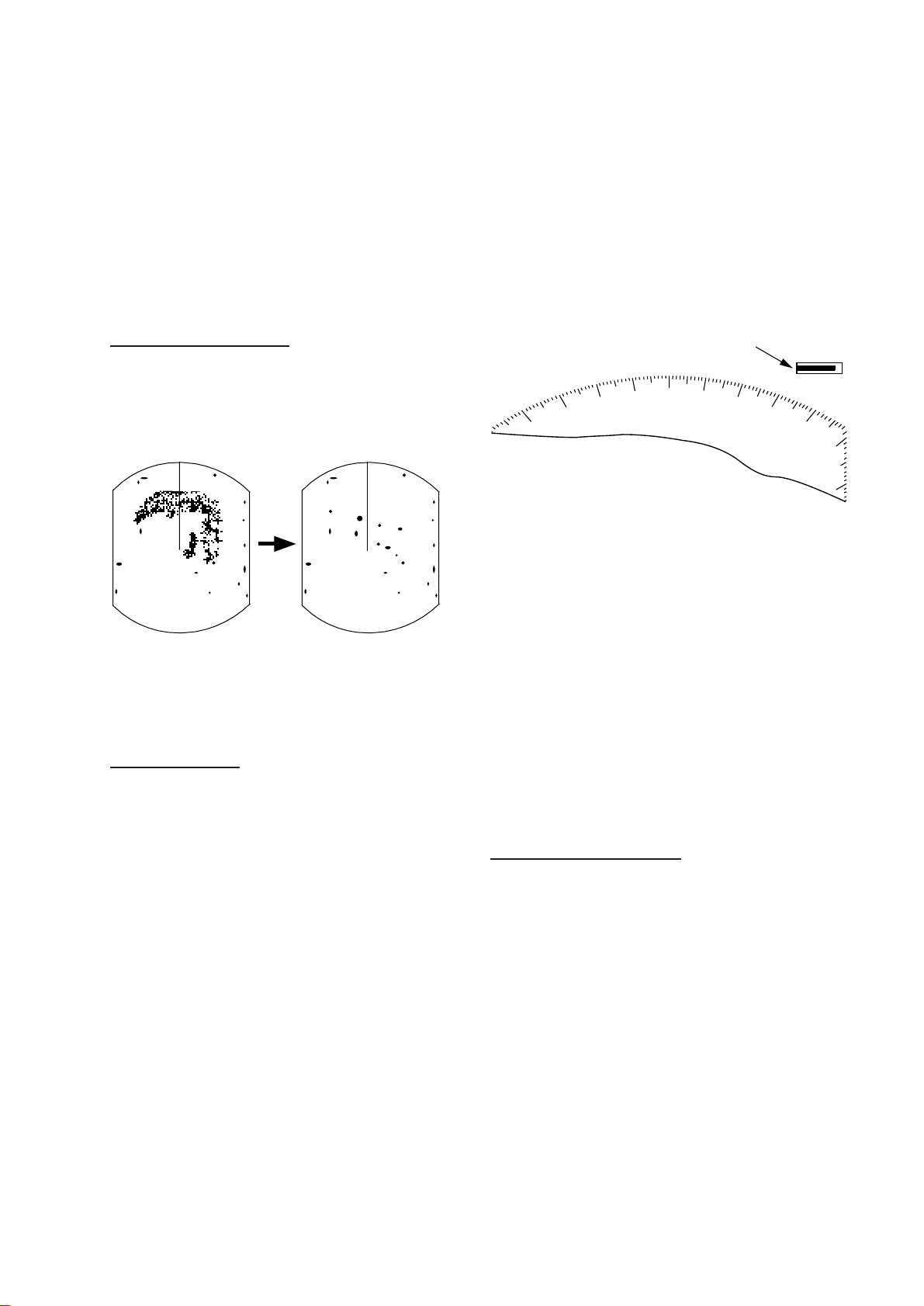
2.17 Suppressing Radar Interference
Radar interference may occur when near another shipborne radar operating in the same
frequency band as your radar. Its on-screen
appearance is many bright dots either scattered at random or in the form of dotted lines
extending from the center to the edge of the
display. Figure 2-15 illustrates interference
in the form of curved spokes. Interference
effects are distinguishable from normal echoes because they do not appear in the same
place on successive rotations of the scanner.
Guard zone
to set
(1) Mentally create
the guard zone to set.
G (IN)
Guard
zone
* G (IN)
Drag cursor
here.
(2) Drag cursor to
top left corner of
zone and press
[GUARD].
G (IN)
Drag cursor
here.
Figure 2-15 Radar interference
Four levels of interference are available, including off: IR1, IR2, IR3 and OFF. IR3
provides the highest level of rejection.
Procedure
1) Press the [MENU] key.
2) Select P/L & Int/Noise Rej & ES and
press the [ENT] key.
3) Select INT REJECT.
(4) Guard zone
completed.
(3) Drag cursor to
bottom right corner
of zone and press
[GUARD].
Figure 2-14 How to set a guard zone
14
4) Select level desired; 2 provides the greatest degree of interference rejection
4) Press [ENT] and [MENU].
IR and level selected appear at the top right
Page 26

corner on the display when the interference
Cursor Cursor
(1) Place cursor
where desired.
(2) Press [OFF CENTER]
key; cursor location
becomes screen center.
rejection circuit is turned on.
2.18 Suppressing Noise Interference
Noise interference appears on the screen as
many bright dots. These dots can be suppressed by turning on the noise rejector. Note
however that there are some forms of noise
interference which this radar cannot suppress.
2.20 Off Centering the Display
Your vessel’s position can be shifted anywhere within 75% of the effective display
area. The primary advantage of the off centered display is that for any range setting,
the view ahead of your vessel can be extended without changing the range or size
of targets.
Procedure
1) Locate the cursor where you want to the
screen center to be.
Procedure
1) Press the [MENU] key.
2) Select P/L & Int/Noise Rej & ES and
press the [ENT] key.
3) Select Noise Reject to ON.
4) Press the [ENT] key followed by the
[MENU] key .
2.19 Selecting Pulselength
Pulselength is the transmission time of a
single radar pulse. The longer the
pulselength the greater the detection range
capability, however range accuracy and
range resolution are reduced.
Pulselength can be selected to short or long
on the 1.5 and 3 nautical mile ranges.
2) Press the [OFF CENTER] key.
OFF CENTER appears at the top left corner
on the display when the display is off centered.
Note: The off centered display is automatically
canceled when the [DISP MODE] key is
pressed.
Figure 2-16 Off centering the display
1) Press the [MENU] key.
2) Select P/L & Int/Noise Rej & ES and
press the [ENT] key.
3) Select Pulselength to SHORT or LONG
6) Press [ENT] and [MENU] key.
15
Page 27

2.21 Echo Trails
Continuous trail
You can show the trails of targets in afterglow . This function is useful for alerting you
to possible collision situations.
Starting echo trail
Press the [TRAIL] key to start the echo trail
function. Afterglow starts extending from
targets and "TRAIL" and the echo trail time
appear at the top right-hand corner of the
display. Press the key again within 3 seconds to select a different trail time, among
15 sec, 30 sec, 1 min, 3min, 6 min, 30 min,
and continuous. In continuous plotting the
time elapsed appears at the top right corner
on the display.
Note: If the range is changed, trails are painted
anew with the newly selected range.
The maximum continuous trail time is 99
minutes and 59 seconds. When the elapsed
time clock counts up to that time the elapsed
time display is reset to zero all trails are
erased and then trailing is restarted.
Adjusting brilliance of afterglow
The brilliance of the trails' afterglow can be
set on the Backlight/Brilliance menu.
1) Press the [MENU] key.
2) Select Backlight/Brilliance and press the
[ENT] key.
3) Select Echo Trails.
4) Select brilliance.
5) Press the [ENT] key followed by the
[MENU] key.
True trails Relative trails
(requires gyro)
Figure 2-17 Appearance of echo trails
Fixed time trails
When the elapsed time clock counts up to
the trail time selected, the elapsed time display freezes. The oldest portions of trails are
erased so only the latest trail, equal in length
to the trail time selected, is shown. Then,
trails start extending again. For example, the
one minute trail time is selected. When the
elapsed time display freezes at 60 seconds,
all but the latest one minute of trails are
erased and then trailing continues.
Canceling echo trails
Press the [TRAIL] key to erase the TRAIL
indication.
2.22 The Navigation Data
Display
Navigation data can be displayed at the
screen bottom if this radar receives navigation input in NMEA 0183 format. Navigation data includes
• position in latitude and longitude or Loran-C time differences (TDs)
• bearing and range to a waypoint selected
on the navigator
• cross track error (XTE—the amount in
nautical miles and the direction the vessel if off course)
• depth
• speed.
If the navigation data include the destination data, waypoint position is denoted on
the radar display by a dashed ring.
16
Page 28

4) Select Nav Data Disp to OFF or ON.
1.5
0.5
DEPTH XTE SPD
350.0m 0.05NML 30.0KT
WAYPOINT POSI L/L
12.0
NM
VRM EBL + CURSOR
0.675
NM
NM
45.0°
240.1°
HDG 326.8°
M
R
0.646
66° 04. 00N
166° 04. 00E
NM
AUTO
308.7°
R
Figure 2-18 Sample nav data display
Setting up the nav data display
1) Press the [MENU] key.
2) Select Nav Data and press the [ENT] key .
5) Select Pos Disp Mode to L/L (latitude and
longitude or TD (Loran C).
6) Select unit of depth measurement to
meters, fathoms, or feet.
7) Select unit of measurement for water tem-
perature to Centigrade or Fahrenheit.
8) Select whether to display nav data or "ST-
BY". "NORM" for stand-by; NAv for
navigation data.
9) Press the [ENT] key followed by the
[MENU] key.
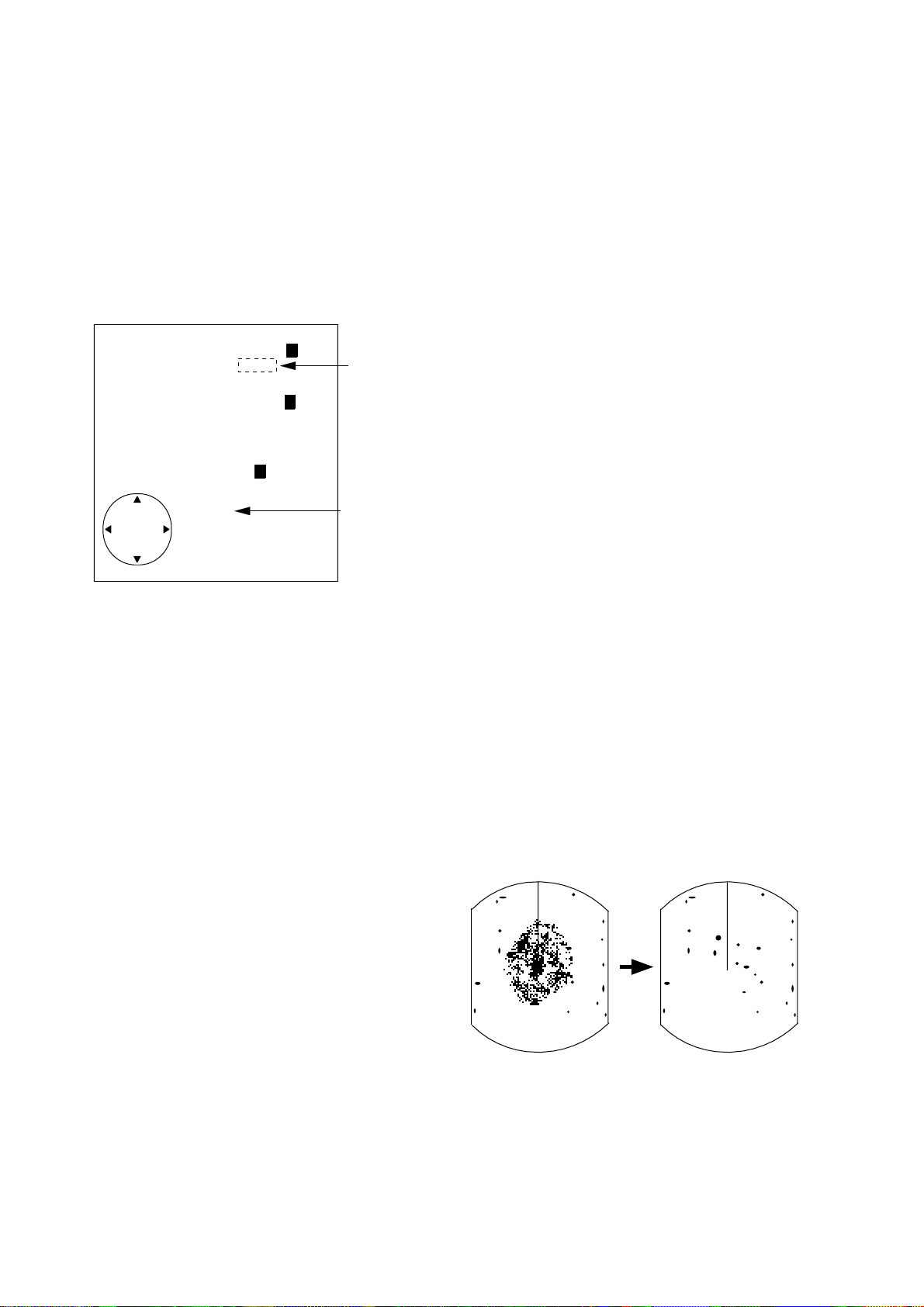
2.23 Echo Stretch (magnifying long range echoes)
Normally, the reflected echoes from long
range targets appear on the display as weaker
and smaller blips even though they are compensated by the radar’s internal circuitry . T o
stretch long range echoes, in the range direction, turn on the echo stretch function.
Distant
echo
● NAV DATA MENU ●
Select item and option
by ▲▼ keys.
1. Navigator
2. Nav Data Disp
3. Pos Disp Mode
4. Depth Unit
5. Temp Unit
6. STBY Display
ALL GPS LC
OFF ON
L/L TD
M FA FT
°C °F
NORM NAV
. . . . . . . . . . . . . . . . .
Press HM-OFF to temporarily
hide menu.
<Press MENU for main menu.>
Figure 2-19 Nav data menu
3) Select Navigator; GPS, Loran C or ALL
(Select all if several navigators are connected to the radar. In this case, position
data is selected in order of GPS, Loran C
and other.)
Echo stretch OFF Echo stretch ON
Figure 2-20 Echo stretch
Turning echo stretch on or off
1) Press the [MENU] key.
2) Select P/L & Int/Noise Rej & ES and
press the [ENT] key.
3) Select Echo Stretch.
4) ON or OFF.
17
Page 29

5) Press the [ENT] key followed by the
[MENU] key . ES appears at the top right
side on the display when the echo stretch
feature is on.
Note 1: This function magnifies not only targets but also sea clutter and radar interference.
For this reason be sure the controls for adjustment of sea clutter and radar interference are
properly adjusted before activating the echo
stretch.
3) Select EBL Ref.
4) Select Rel(ative) or True.
5) Press the [ENT] key followed by the
[MENU] key.
2.26 Watchman
How watchman works
Note 2: Echo stretch is inoperative on ranges
from 0.25 to 0.75 nautical miles. ES appears
in reverse video when you try to turn on the
echo stretch in those ranges.
Note 3: When the echo stretch function is selected, Interference Rejection level #3, along
with the Noise Rejection circuits, are automatically enabled. These can be turned off via menu
selection if desired.
2.24 Selecting Unit of Measurement for Range
The unit of measurement for the VRM and
cursor can be nautical miles, kilometers, or
statute miles. Y ou may select unit desired as
follows.
1) Press the [MENU] key.
2) Select Mode & Function and press the
[ENT] key .
3) Select VRM Unit to nm, km, or sm.
4) Press [ENT] followed by [MENU] key.
The watchman function periodically transmits the radar for about one minute to check
for targets in a guard zone. If it finds change
in the zone from the previous transmission
it sounds the aural alarm, cancels the watchman function, and transmits the radar continuously. This feature is useful when you
do not need the radar’s function continuously but want to be alerted to radar targets
in a specific area.
Tx
1 min
Watchman
starts.
St-by
5, 10 or
20 min
Tx
1 min
St-by
5, 10 or
20 min
Figure 2-21 How watchman works
Turning on watchman
1) Create a guard zone (usually 360 degrees)
with the guard alarm function.
2) Press the [MENU] key.
3) Select Mode & Function and press the
[ENT] key.
2.25 Selecting Bearing Reference
Bearing can be displayed relative to north
(relative bearing) or relative to true north
(true bearing) as follows. (True bearing requires heading sensor input.)
1) Press the [MENU] key.
2) Select Mode & Function and press the
[ENT] key .
18
4) Select W atchman.
5) Select watchman rest interval (amount of
time until next rotation of antenna); 5
minutes, 10 minutes or 20 minutes.
6) Press the [ENT] key followed by the
[MENU] key. Then, WATCHMAN appears, and the radar transmits for one
minute and then goes into stand-by.
Canceling watchman
Page 30

Press any key while the radar is transmitting. (Pressing a key during stand-by causes
the radar to go to warm-up condition.)
2.27 Erasing the Heading Marker
The heading marker continuously appears
on the display and shows your vessel’s heading. When this mark obscures a tar get echo,
you can temporarily erase it by pressing and
holding down the [HM OFF] key. Release
the key to redisplay the marker.
vessel’s position in latitude and longitude,
the range and bearing to waypoint, speed,
course, date, time and cross track error may
be input to this radar, and be seen in the bottom text area during stand-by . Further , with
video sounder input, depth may be displayed, both digitally and in graph form.
CAUTION
The barometer and depth displays are intended
as reference. Any data displayed by them
should be used with extreme caution.
Procedure
2.28 Deselecting Ranges
This radar has 14 or 15 ( MODEL 841)
ranges, some which you may not require.
You can deselect up to eight ranges as follows.
1) Press the [MENU] key.
2) Select Mode & Function and press the
[ENT] key .
3) Select Range and press the [ENT] key.
Active ranges appear in reverse video.
4) Press t or s to select range to disable
(or enable). Current selection is underlined.
5) Press [ENT].
6) Repeat steps 4 and 5 to disable (or enable) other ranges.
7) When finished, press the [MENU] key.
2.29 Displaying Navigation
Data During Stand-by
Various navigation data can be displayed
during stand-by . A barometer is built in this
radar; atmospheric pressure appears, in
graph form, on the navigation data display
during stand-by. If your navigation aid can
output data in NMEA 0183 data format, your
1) Press the [MENU] key.
2) Select the Nav Data menu and press the
[ENT] key.
3) Select STBY Display to NAV and press
the [ENT] key.
4) Press the [MENU] key.
Note 1: The depth display scale changes automatically with depth and the maximum depth
is 1,000 meters.
Note 2: The barometer display is updated
hourly, thus the data shown may not be the
latest.
ST–BY
(hPa)
(Mbar/hPa)
1020
1010
1000
900
-9 -6 -3
-12
(HOUR)
BAROMETER DEPTH
DATE TIME TEMP CRS
(MIN)
12
0
500
1000
(m)
08.22 15:19 30.0°C 0.0°M
DEPTH XTE SPD
827 m 0.6NM R 30.0KT
WAYPOINT POSI L/L
65°43.98N
12.0NM 114.8°R
165°43.96E
XTE
L R
1 10
0.5
(NM)
XTE
0.5
Figure 2-22 Navigation data display
during stand-by
19
Page 31

2.30 Outputting Cursor Position to Navigator
Cursor position (NMEA0183 data sentence
TLL) can be output to the navigator connected to this radar by pressing and holding
down the [HM OFF] key.
2.31 Displaying Cursor Position, Range and Bearing to Cursor
The cursor data indication at the bottom of
the display can show cursor position in latitude and longitude or the range and bearing
from own ship to the cursor . Y ou can select
the indication desired by pressing the [HM
OFF] key.
2.32 Visual Alarm Indications
This radar display various visual alarms to
alert you to error.
Table 2-1 Visual alarm indications
rorrEmralalausiV
eslupgnidaehoNGNISSIMGISDH
eslupgniraeboNGNISSIMGISPB
langisgnidaeH
ffodenrut
The heading signal visual alarm may be
cleared by pressing the [DISP MODE] key.
sraeppa(*.***
)gnidaehsa
20
Page 32

3. INTERPRETING THE DISPLAY
As an aid to navigation, radar can be a very
valuable tool. No other electronic navigation aid can give you the ability to spot vessels coming at you in the fog, or tell you the
location of the inlet to the harbor in the pitch
black of night.
T o help you understand what your radar can
(and cannot) do for you this chapter covers
Radar horizon
Radar is essentially a “line-of-sight” phenomenon. That means you have just about
the same range to horizon with a radar as
you do with your own eyes. However under
normal atmospheric conditions, the radar
horizon is 6% greater than the optical horizon. Therefore, if the target does not rise
above the horizon the radar beam cannot be
reflected from the target.
The distance to the horizon from the scanner, under normal conditions, is calculated
by the following formula.
• the characteristics of the radar wave
• target properties and radar wave reflection
• range and bearing resolution, and
• false echoes.
3.1 The Radar Wave and
Radar Horizon
How the radar wave travels
The radar wave tends to travel in straight
lines at the speed of light. However, it is
subject to bending or refraction in the atmosphere, the amount depending on region and
density .
Super -refraction
Super-refraction is a condition in which
there is an upper layer of warm dry air over
a surface layer of cold, moist air. Radar
waves bend downward and thus increase the
ranges at which targets may be detected.
Sub-refraction
Sub-refraction is the reverse condition of
super-refraction; a layer of cold air is above
a layer of warm air. Radar waves bend upward and thus decrease the ranges at which
targets may be detected.
Rmax = 2.2 x
h1+h2
Where Rmax: Radar horizon (mile), h1: Antenna height (meters), h2: Target height
(meters)
D
h
1
Horizon
h
2
Wave
path
Figure 3-1 Radar horizon
3.2 Target Properties and Radar Wave Reflection
Generally, larger targets can be seen on the
radar display at greater ranges, provided
line-of-sight exists between the scanner and
target. However, a large target with poor
reflecting properties may not be detected as
easily as a smaller target with better reflecting properties. For example, you might expect a lighthouse to be a good radar target
because of its size. In actuality the return
echo is weak since the conical shape diffuses
most of the radiated energy.
A ship whose hull is made of conducting
materials, such as steel, will return a relatively strong echo.
21
Page 33

On the other hand, hulls made from wood
or fiberglass return much weaker echoes.
Vertical surfaces, such as a cliff, are good
targets provided they face the radar. Conversely , horizontal and smooth surfaces such
as mudbanks, sandy beaches, and gently
sloping hills make poor targets because they
disperse rather than reflect most of the energy that strikes them.
The strongest radar echoes known come
from built-up areas, docks, etc., because
these targets are less subject to changes in
aspect. These types of tar gets have three flat,
smooth surfaces mutually at right angles.
Some radar buoys are arranged this way so
as to deliberately increase their detection
range.
3.3 Range Resolution
3.4 Bearing Resolution
Bearing resolution is a measure of the capability of a radar to display as separate targets the echoes received from two targets
which are at the same range and are close
together.
The principal factor which affects bearing
resolution is horizontal beamwidth. T wo targets at the same range must be separated by
more than one beamwidth to appear as separate pips.
Target
Horizontal
beamwidth
Direction of
scanner rotation
Target
Radar is able to display two
distinct target echoes.
Range resolution is a measure of the capability of a radar to display as separate pips
the echoes received from two targets which
are on the same bearing and are close together.
The main factor which affects range resolution is pulselength. T wo tar gets on the same
bearing, close together, cannot be seen as
two distinct echoes on the display unless
they are separated by a distance greater than
one-half the pulselength.
Radar is able to display two
Transmitted
radar
pulse
Transmitted
radar
pulse
Radar cannot display targets as
separate echoes because they
are within the pulselength.
distinct target echoes.
Target
Target
Horizontal
beamwidth
Direction of
scanner rotation
Radar cannot display targets as
separateechoes because they
are within the beamwidth.
Figure 3-3 Bearing resolution
3.5 False Echoes
Occasionally false echoes appear on the
screen at positions where there is no target.
In some cases the effects can be reduced or
eliminated. The operator should familiarize
himself or herself with the appearance and
effects of these false echoes, so as not to
confuse them with echoes from legitimate
contacts.
Multiple echoes
22
Figure 3-2 Range resolution
Multiple echoes occur when a short range,
strong echo is received from a ship, bridge,
or breakwater . A second, a third or more ech-
Page 34

oes may be observed on the display at
Heading
mark
True
echo
Indirect
echo
Heading
mark
True
echo
Indirect
echo
Indirect
path
Direct
path
Scanner
Obstruction
(mast, funnel,
etc.)
Own
ship
Target
Bridge
Direct
path
Indirect
echo
,
,
Target
,
Indirect
path
double, triple or other multiples of the actual range of the target as shown in Figure
3-4. Multiple reflection echoes can be reduced and often removed by decreasing the
sensitivity or properly adjusting the STC.
True
echo
Target
Indirect echoes
Indirect echoes may be returned from either
a passing ship or returned from a reflecting
surface on your own ship, for example, a
stack. In both cases, the echo will return from
a legitimate contact to the antenna by the
same indirect path. The echo will appear on
the same bearing of the reflected surface,
but at the same range as the direct echo. Figure 3-6 illustrates the effect of an indirect
echo. Indirect echoes may be recognized as
follows:
Own ship
Multiple
echo
Figure 3-4 Multiple echoes
Side-lobe echoes
Every time the scanner rotates, some radiation escapes on each side of the beam—
called “side-lobes.” If a target exists where
it can be detected by the side-lobes as well
as the main-lobe, the side-lobe echoes may
be represented on both sides of the true echo
at the same range, as shown in Figure 3-5.
Side-lobes show usually only at short ranges
and from strong targets. They can be reduced
through careful reduction of the sensitivity
or proper adjustment of the STC.
Main-lobe
True echo
• they usually occur in a shadow sector
• they appear on the bearing of the obstruction but at the range of the legitimate contact
• when plotted, their movements are usually abnormal, and
• their shapes may indicate they are not direct echoes.
Scanner
Side-lobe
Spurious
target
Figure 3-5 Side-lobe echoes
Figure 3-6 Indirect echoes
23
Page 35

Blind and shadow sectors
3.6 Nautical Chart and Radar
Funnels, stacks, masts, or derricks in the path
of antenna may reduce the intensity of the
radar beam. If the angle subtended at the
scanner is more than a few degrees a blind
sector may be produced. Within the blind
sector small targets at close range may not
be detected while larger targets at much
greater ranges may be detected. See Figure
3-7.
Vessel taller
than wharf
Wharf
Wharf
Blind sector
(no echo)
Mast, etc. in path
of radar beam
Size of blind sector
depends on target
size and range.
Picture
Under normal conditions, a picture which
is similar to a nautical chart can be obtained
on the radar display. However, a radar cannot:
• show targets which are below the horizon.
• show a target which is hidden by a larger
one.
• see around corners (for example, seawall).
• distinguish between two targets which are
very close together, either in range or
bearing. For example, a vessel towing
another will probably appear as one vessel, as both will be covered by the beam
at the same time.
The nautical chart and radar picture shown
in Figure 3-8 are from the Kada Inland Sea
in southwestern Japan.
Figure 3-7 Blind and shadow sectors
Black areas are
strong reflection
targets.
Coastline
difficult to
display.
Actual topography Radar display
Figure 3-8 Nautical chart and associated
radar picture
24
Page 36

4. MAINTENANCE & TROUBLESHOOTING
This chapter tells you how to keep your radar in good working order. Before reviewing this chapter please read the safety
information which follows.
RF RADIATION HAZARD
The radar scanner emits high fre-
quency radio radiation which can
be harmful, particularly to your eyes. Never
look directly into the scanner from a distance
of less than two feet when the radar is in
operation as you could injure the cornea of
your eyes. Always make sure the radar is
set to stand-by or is turned off before starting work on the scanner unit.
4.1 Safety Information
WARNING
Hazardous voltages.
Can shock, burn or
cause death.
Only qualified personnel should work inside
the units of the radar.
safety , precautions must always be exercised
when reaching inside the equipment for the
purpose of maintenance or service. For this
reason, only qualified personnel totally familiar with electrical circuits and service
manual should work inside the display unit
or scanner unit.
ELECTRICAL
SHOCK
HAZARD
This equipment
uses high voltage
electricity which
can shock, burn or
cause death.
While the equipment has been designed with
consideration for
the operator’s
T urn off the power befor e performing any maintenance or
!
troubleshooting procedure.
25
Page 37

4.2 Preventative Maintenance
4.3 Replacing the Fuse
Regular maintenance is important for good
performance. Always keep the equipment as
free as possible from dirt, dust, and water
splashes. Make sure all screws securing the
components are properly tightened.
The 5A fuse in the power cable protects the
equipment against reverse polarity of ship’ s
mains, overcurrent, and equipment fault. If
the fuse blows, find the cause before replacing it. Never use a fuse rated for more than
5A–serious damage to equipment may re-
A maintenance program should be estab-
sult and void the warranty.
lished and should at least include the items
listed in Table 4-1.
Table 4-1 Recommended maintenance program
doirePmetItniopkcehCskrameR
6ot3
shtnom
tinu
stlobgnixiF
annetnarof
emodaR
ssenilnaelc
.noisorroc
dnassenthgitrofkcehC
.retawhserfahtiwemodar
taoC.stlobdedorrocecalpeR
.tnalaesevisorroc-itnahtiwstlob
emodarehtnolairetamngieroF
elbaredisnocaesuaclliwecaf
ehtnaelC.ecnamrofrepnipord
gninaelcdednemmocerylnoehT
esutonoD.lohoclasitnega
nacyeht;stnegagninaelcrehto
.sgnikramdnatniapevomer
emodaR
revoc
.emodarehtotni
DCL,emitni,lliwDCLehT
.htolc
shtnom6
raey1ot
tinuyalpsiD
srotcennoc
.noisorroc
tnenamreP.raewrofkcehC
lanretnis'annetnaehtotegamad
skaelretawfitluserlliwyrtiucric
.ecivresrof
tsudfognitaocaetalumucca
.erutcipehtmidotsdnethcihw
tfosahtiwylthgilDCLepiW
dnanoitcennocthgitrofkcehC
.sgnikram
.tnemecalperrof
gnilaesfotnuomallams
ebdluohstidnuofsikcarcafI
agnisuybderiaperyliraropmet
uoY.evisehdarodnuopmoc
relaedruoytcatnocnehtdluohs
otsrenaelclacimehcesutonoD
;tinuyalpsidehtfotrapynanaelc
dnatniapevomernacyeht
relaedruoytcatnoc,dedorrocfI
26
Page 38

4.4 Troubleshooting
Table 4-2 contains simple troubleshooting
procedures which you can follow to try to
restore normal operation. If you cannot restore normal operation, do not attempt to
check inside any unit of the radar system.
Any repair work is best left to a qualified
technician.
Table 4-2 Troubleshooting table
...fI...tuB...nehT
ehtdesserpuoy
nrutotyek]REWOP[
radarehtno
sahradareht
uoydnapudemraw
ehtdesserp
otyek]XTYB-TS[
timsnart
detsujdaevahuoy
CTFhtiwniageht
ffoCTSdna
thgilton
roopsitsartnoc
erasretcarahc
detrotsid
etator
dnasretcarahc
erasnoitacidni
lamronba
raeppastegrat
dnasnoitacidni(
)odsrekram
)odstegratdna
seodlenaplortnoceht
.unem
.elbacrewopniesufkcehc•
nosraeppagnihton
yalpsidroyalpsideht
tonseodannetnaeht
.tes
ronesionrehtien
ronsnoitacidnirehtien
esion(raeppasrekram
.enotehtgnitsujdayrt•
).enotyalpsidtceffa
.ecivrestseuqer•
.ecivrestseuqeR
-kcablenaplortnocehtgnitsujdayrt•
gnithgilkcaB/ecnaillirBehtnognithgil
.degrahcsidevahyamyrettab•
yamerutarepmettneibmaemertxE(
.tinuannetnaniebyammelborpeht•
ehtkcehcnaicinhcetdeifilauqaevah•
.egamadrofelbaclangiskcehc•
.egamadrofelbaclangiskcehc•
enillaidar(peewseht
ehtdnuoragnipeews
tonsi)yalpsid
htiwdezinorhcnys
noitatorannetna
niegnahconsiereht
.ytivitisnes
desserpsiyekasneppahgnihton.ecivrestseuqeR.ytluafebyamyek•
annetnaehtniebyammelborpeht•
.ecivrestseuqeR.tinu
.ecivrestseuqer•
27
Page 39

4.5 Self Test
The self test facility checks the keyboard,
ROM and RAM for proper operation. You
may run the test as follows.
1) Press the [MENU] key.
2) Select Self Check. The following display
appears.
[SELF TEST]
KEY BOARD TEST
Press each key. Corresponding key on
the screen turns
black.
Prog NO.: 03590951**
ROM: OK
RAM: OK
On Hours: 000019.5H
Tx Hours: 000019.5H
<MENU>=MAIN MENU
Figure 4-1 Self test screen
3) To check the keyboard, press a key. Its
corresponding location on the display
lights in black if the key is operating properly.
4) T o escape the test, press the [MENU] key .
The ROM and RAM are automatically
checked. If NG (No Good) appears to the
right of ROM or RAM indication, contact
your dealer for advice.
28
Page 40

5. INSTALLATION
This chapter covers installation. Installation
mainly consists of the following:
• siting and mounting the display unit and
the antenna unit
• connection of the signal cable and the
power cable
• establishing the ground
• connecting optional equipment, and
• adjustments.
NOTICE
The installation of this equipment requires
certain electrical and mechanical skills. If the
owner of the equipment has doubts about his
or her technical abilities, we recommend that
the equipment be installed by a qualified
technician.
• A magnetic compass will be affected if
placed too close to the antenna unit. Observe the minimum compass safe distances to prevent deviation of a magnetic
compass:
Table 5-1 Compass safe distances
ledoMdradnatS
ssapmoc
128m7.1m4.1
148m4.1m1.1
gnireetS
ssapmoc
• Typical mounting location for a sailboat
and power boat are shown in Figure 5-1.
5.1 Antenna Unit Installation
Mounting considerations
When selecting a mounting location for the
antenna unit keep in mind the following
points.
• Install the unit on top of the wheelhouse
or on the radar mast on an appropriate
platform. It should be placed where there
is a good all-round view with, as far as
possible, no part of the ship’s superstructure or rigging intercepting the scanning
beam. Any obstruction will cause shadow
and blind sectors.
• Locate the unit at least two meters away
from a direction finder antenna to prevent
interference to the direction finder.
• In order to minimize the chance of picking up electrical interference, avoid where
possible routing the signal cable near
other onboard electrical equipment. Also
avoid running the cable in parallel with
power cables.
Figure 5-1 Typical antenna unit mounting
location for sailboat and power boat
29
Page 41

Mounting procedure for MODEL 821
Mounting platform
Removing packing materials
1) Open the radome cover carefully. Remove mounting hardware at the bottom
of the radome base assembly; four each
of M10 bolts, spring washers and flat
washers. This hardware may be dis-
carded; do not use them to fix the antenna unit to the mounting platform.
Flat
Spring
washer
washer
M10 x 20
hex head bolt
3) Prepare a platform of 5 to 10mm in
thickness for the antenna unit. (For sailboats, an optional mounting bracket
which can be fixed to a mast is available. See page 35 for details.)
The mounting surface must be parallel
with the waterline and provided with five
holes whose dimensions are shown in the
outline drawing at the back of the
manual. Four 10mm holes for fixing, and
one 20mm hole for the vent tube.
There is a cable entry (cable gland) outside the antenna unit which should face
the stern direction. The unit is adjusted
so a target echo returned from the bow
direction will be shown on the zero degree (heading marker) position on the
screen. When drilling holes, be sure they
are parallel with the fore and aft line.
Figure 5-2 Antenna unit (MODEL 821),
showing location of mounting hardware
2) Unfasten the fixing bolts for the radome
base.
Fixing
bolt
Rubber
washer
Figure 5-3 Antenna unit (MODEL 821),
showing location of fixing bolts
Vent tube
Moisture can condense inside the radome, causing corrosion, if a means is
not provided to keep moisture out of the
radome. A vent tube fitted on the base of
the radome allows the radome to
"breathe" while not allowing entry of
water from outside into the radome. Be
sure the tube is kept free of foreign materials and is not pinched or kinked. The
vent tube extends downward by 27mm
from the radome base. Ensure the vent
tube extends downward before mounting the radome base.
4) Find the cable entry on the radome base.
Position the radome base so the cable
entry faces the stern direction. (This
alignment must be as accurate as possible.)
30
Page 42

5) Make sure the vent tube is in the correct
,
,
,
,
,
position, and then fasten the radome base
to the mounting platform with four each
of M10 x 20 hex bolts, flat washers and
spring washers (supplied). Do not overtighten the bolts; the tightening torque
should be between 200 and 250 kg cm.
Radome base
assy.
15 mm
,,,,,,,,,,,,,,,,
,,,,,,,,,,,,,,,,
Flat
washer
Spring
washer
,,,,
,,,,
,,,,
5-10
mm
Platform
M10 x 25
hex bolt
Wiring and final preparation inside the
antenna unit for MODEL 821
1) Drill a hole of at least ø27mm through
the deck or bulkhead to run the signal
cable between the antenna unit and the
display unit.
2) Pass the cable through the hole. Then,
seal the hole with sealing compound for
waterproofing.
3) Unfasten the cable gland and pass the
signal cable through the hole at the rear
of the radome base. The cable has three
plugs which you connect to the antenna
unit.
4) Secure the cable with the cable clamping plate and gaskets. Fasten the shield
to one of the fixing screws for the cable
clamping plate to ground the shield.
Figure 5-4 How to fasten the radome base
to the mounting platform
31
Page 43

5) Connect three plugs to the antenna unit:
P801 (9 way), P813 (2 way), and P810
(10 way).
Figure 5-5 Antenna unit (MODEL 821), inside view
6) Put the radome on the radome base assembly. The arrow should face toward
the bow.
Ship's
bow
J813
J810
J801
TP804
7) Tighten the fixing bolts for the radome.
8) The cable run must be properly supported, and must not be used to provide
impromptu foot-holds or hand-holds!
Clips or hangers should be employed every 20 cm.
32
Figure 5-6 How to position the
radome cover (MODEL 821)
Page 44

Mounting procedure for MODEL 841
Mounting platform
Removing packing materials
1) Open the radome cover carefully. Remove mounting hardware at the bottom
of the radome base assembly; four each
of M10 bolts, spring washers and flat
washers. This hardware may be dis-
carded; do not use them to fix the antenna unit to the mounting platform.
Flat
Spring
washer
washer
M10 x 20
hex head bolt
Figure 5-7 Antenna unit (MODEL 841),
showing location of mounting hardware
2) Unfasten the four fixing bolts securing
the radome cover to the radome base. Lift
radome carefully to remove the antenna
radiator packing materials.
Figure 5-8 Antenna unit (MODEL 841),
showing location of fixing bolts
3) Prepare and fasten a platform of 5 to
10mm in thickness to the mounting location. (For sailboats, an optional mounting bracket which can be fixed to a mast
is available. See page 35 for details.)
The mounting surface must be parallel
with the waterline and provided with six
holes whose dimensions are shown in the
outline drawing at the back of the
manual; four 12mm holes for fixing, and
one 27 mm hole for cable entry, and one
20mm hole for the vent tube.
There is a cable entry (cable gland) outside the antenna unit which should face
the stern direction. The unit is adjusted
so a target echo returned from the bow
direction will be shown on the zero degree (heading marker) position on the
screen. When drilling holes, be sure they
are parallel with the fore and aft line.
Vent tube
Moisture can condense inside the radome, causing corrosion, if a means is
not provided to keep moisture out of the
radome. A vent tube fitted on the base of
the radome allows the radome to
"breathe" while not allowing entry of
water from outside into the radome. Be
sure the tube is kept free of foreign materials and is not pinched or kinked. The
vent tube extends downward by 27mm
from the radome base. Ensure the vent
tube extends downward before mounting the radome base.
4) Find the cable entry on the radome base.
Position the radome base so the vent tube
faces the stern direction. (This alignment
must be as accurate as possible.)
33
Page 45

5) Make sure the vent tube is in the correct
,
,
,
,
,
position, and then fasten the radome base
to the mounting platform with four each
of M10 x 20 hex bolts, flat washers and
spring washers (supplied). Do not overtighten the bolts; the tightening torque
should be between 200 and 250 kg cm.
Radome base
assy.
Wiring and final preparation inside the
antenna unit for MODEL 841
1) Drill a hole of at least ø20mm through
the deck or bulkhead to run the signal
cable between the antenna unit and the
display unit.
2) Pass the signal cable through the hole.
Then, seal the hole with sealing compound for waterproofing.
15 mm
,,,,,,,,,,,,,,,,
,,,,,,,,,,,,,,,,
,,,,
,,,,
,,,,
5-10
mm
Flat
washer
Platform
Spring
washer
M10 x 25
hex bolt
Figure 5-9 How to fasten the radome base
to the mounting platform
3) Unfasten the cable clamping plate by
loosening four M4 screws and removing
two gaskets at the radome base.
4) Pass the cable through the hole at the
bottom of the radome base. Three plugs
are attached at one end of the signal
cable.
5) Secure the cable with the cable clamping plate and gaskets removed in step 3.
6) Connect the ground wire between one
of the fixing screws for cable clamping
plate and the IF amplifier chassis.
7) Referring to Figure 5-10, mate the 9 way
and 2 way plugs to the MD Board. Remove the lid of the IF Board and mate
the 14 way plug there. Reattach the lid.
Figure 5-10 Antenna unit (MODEL 841), inside view, shield cover removed
34
Page 46

8) Put the radome on the radome base assembly. The arrow should face toward
the bow.
Figure 5-11 How to position the
radome cover (MODEL 841)
9) Tighten the fixing bolts for the radome.
10) The cable run must be properly supported, and must not be used to provide
impromptu foot-holds or hand-holds!
Clips or hangers should be employed
every 20 cm.
Figure 5-12 Optional mounting bracket installation for sailboat
35
Page 47

5.2 Display Unit Installation
Mounting considerations
When selecting a mounting location for the
display unit keep in mind the following
points.
• The display unit is designed and constructed to be splashproof, thus it can be
installed outdoors. You can even hose it
down after a day’s outing. If it is to be
installed outdoors, we recommend installing it an enclosed cabinet, for maximum
protection against the marine environment.
• The temperature and humidity of the
mounting location should be stable and
moderate. No LCD can provide adequate
contrast if the ambient temperature is too
extreme.
• The display unit consumes only a moderate amount of power , so there is no need
for forced air ventilation. However, you
should provide adequate space behind and
around the unit to permit circulation of
air and to provide convenient access to
the rear connectors.
• Even though the picture is quite legible
even in bright sunlight, keep the display
unit out of direct sunlight or at least
shaded because of heat that can build up
inside the cabinet.
• Locate the display unit in a position where
you can view and operate it conveniently
but where there is no danger of salt or
fresh water spray or immersion.
• The orientation of the display unit should
be so the radar screen is viewed while the
operator is facing in the direction of the
bow. This makes determination of your
position much easier.
• Make sure you allow enough clearance
both to get to the connectors behind the
unit and to allow you to get your hands
in on both sides to loosen or tighten the
mounting knobs. Make sure you leave at
least a foot or so of “service loop” of
cables behind the unit so it can be pulled
forward for servicing or easy removal of
the connectors.
• A magnetic compass will be affected if
placed too close to the display unit. Observe the minimum compass safe distances to prevent deviation of a magnetic
compass: standard compass, 0.7 meters,
and steering compass, 0.5 meters.
Mounting procedure
The display unit is designed to be mounted
on a tabletop.
1) Using the hanger as a template, mark
screw locations in the mounting location.
2) Fix the hanger to the mounting location
with four M6 tapping screws (supplied).
3) Fit the knob bolts to the display unit.
4) Install the display unit in the hanger.
5) Tighten the knob bolts securely.
36
Page 48

ø6
4 FIXING HOLES
10mm
222(8.7")
236(9.3")
Cutting size for flushmount
274
(10.79")
*80
(3.15")
18
(0.71")
238
(9.37")
:SERVICING CLEARANCE
*
Figure 5-13 How to mount the display unit
18
(0.71")
(0.79")
*80
(3.15")
20
130
(5.12")
100
(3.94")
10
(0.39")
*140
(5.51")
37
Page 49

Connections
Connect the signal and power cables, the
ground wire and optional equipment as
shown in Figure 5-14.
Power cable connector
Connect power
cable here.
10.2-31.2VDC
1
3 GND
2
Signal cable connector
Connect signal cable
from antenna here.
DJ-1
OPTION
MARINE RADAR
TYPE
SER.NO.
DATE
COMPASS SAFE DISTANCE
STD M STEER M
EQUPMENT CLASS
FURUNO ELECTRIC CO., LTD
RP
HDG
NMEA
Covered.
(not use)
HDG connector
Connect heading
sensor nere.
NMEA connector
Connect navaid
nere.
OPTION connector
Connect navaid,
video sounder, etc.
here.
Ground terminal
Connect ground wire between
here and ship's ground.
CAUTION
Tigthen the boot-boud securely to ensure
watertightness. See page 44.
Figure 5-14 Display unit, rear view
38
Page 50

Navigation aid, video sounder
connection
If your navigation aid can output data in
NMEA 0183 data format, your vessel’s position in latitude and longitude, the range and
bearing to waypoint, speed, and course may
be input to this radar, and be seen in the bottom text area.
SPU-9180
DISPLAY
UNIT
J61
Cable supplied
with radar
(connector assy.
03-1796(5))
VIDEO
SOUNDER
Further, if your video sounder can output
depth in NMEA 0183 data format, depth can
be displayed on the navigation data displayed in graph form during stand-by.
You will need an NMEA cable:
For navaid;
Type Code no. Remarks
MJ-A6SPF0012-050 000-134-424 6P-6P(5m)
MJ-A6SPF0012-100 000-133-817 6P-6P(10m)
For E/S;
Type Code no. Remarks
MJ-A6SPF0011-050 000-132-224 6P-4P(5m)
MJ-A6SPF0011-100 000-132-336 6P-4P(10m)
Two NMEA connectors are provided at the
rear of the display unit: the NMEA connector and the OPTION connector.
Heading Sensor Connection
Solder and
tape.
Cable supplied
with video sounder
Figure 5-15 How to connect external
equipment to the OPTION connector
3) Cover signal cable at junction with dis-
play unit with silicone sealant.
Distribution NAV data to the other
equipment
This radar can output NAV data received
from a navaid to an echosounder or video
plotter by making the modifications as
shown in below.
J55 (NMEA)
SPU9180
Navaid
Heading signal can be connected to the
“HDG” connector. 10 m cable assembly is
optionally available.
Type Code no. Remarks
MJ-A6SPF0007-100 000-125-237 C-2000
MJ-A6SPF0009-100 000-125-236 AD-100
The OPTION connector
To connect external equipment to the OPTION connector;
1) Remove the plastic cover on the connector .
2) Connect equipment to J61 on the SPU
Board as shown in Figure 5-15.
TLL, RSD
MODEL 821/841, FMD-811
The position data from navaid can be
used for the echosounder if a video
plotter is not connected.
J61
Echosounder
Video plotter
Procedure
1. Unfasten the nuts fixing the waterproof
connector to remove the covers of the
power and display unit.
2. Remove all connectors from SPU Board
(SPU-9180).
3. Unfasten three screws to remove the
board.
4. Remove JP3, R91 and R92 on the parts
side of SPU Board.
39
Page 51

.
Remove JP3.
SPU-9180
Parts side
9. Replace the covers removed in step 1.
10.Connect navaid and other equipment to
radar.
11.T urn on the radar and confirm that NAV
data in properly received at the radar and
external equipment.
JP3 JP4
R91
R92
Remove R91 and R92.
R93
R94
R95
Q16
Q15
R90
R91
CR14
5. Add jumper wire between J55 pin
#3(RXD-H) and J61 pin #1(TXD-H).
6. Add a jumper wire between J55 pin
#4(RXD-C) and J61 pin #5(SHIELD).
Add the jumper wire between J61#5 and J55#4.
R91
R92
JP3 JP4
J55
J61
5
1
Add the jumper wire between J61#1 and J55#3
R69
C27
3
4
R70
R93
R94
R95
Q16
Q15
R90
R91
CR14
5.3 Installation Check List
After completing the installation it is a good
idea to check for proper installation. Follow
the checklist below and tick boxes to show
proper completion.
❒ Is the vent tube on the antenna housing
on the stern side?
❒ Are the four bolts for fixing the radome
tightened?
❒ Is the signal cable waterproofed at the
radome base?
❒ Is the signal cable secured against a mast
or bulkhead?
❒ Is the cable gland or cable entry on the
deck fully waterproofed?
7. Connect the NMEA cable to the connector assy (03-1796/5P, supplied with
radar) as shown in the figure below.
8. Connect the 5P connector to J51 on SPU
Board.
❒ Are the connections to the battery of
correct polarity?
❒ Are all the antenna and display units
grounded?
Solder
NMEA cable
NMEA cable
Echosounder
Other Equipment
(Telesounder data not be mixed.)
40
Page 52

❒ Are all connectors at the rear of the
display unit fastened securely?
CAUTION
If it is necessary to open the display unit, be sure
the rear cover is fitted to the front chassis
properly when closing the rear cover. When
reassembling, first turn off the unit and then
press the center of the rear cover to plug in the
multipin connector on the rear cover.
5.4 Initial Adjustment of Picture
5) Select minimum range. Press the
[ECHO] key and press the cursor pad to
select STC-AUTO, if it is not already selected.
5.5 Displaying the Installation
Menus
Two sets of installation menus, Installation
Setup 1 and Installation Setup 2 enable entry of initial settings and adjustment of the
radar.
Follow the procedure below to obtain proper
radar picture.
1) Press the [POWER] key on the display
unit. The display should light. Wait until
the message "ST-BY" appears on the
screen. (About 1:30 for the 0821 and 2:30
for the 0841.)
2) Press [TX ST -BY] key to transmit. The
radar will start transmitting, and you will
probably see some targets around you,
even though the radar is not yet properly
adjusted.
3) Select a long range.
4) Press the [ECHO] key. The following
display appears.
AUTO 1 2 3
GAIN
STC
A/C RAIN 00
FTC 0 1 2
◆
◆
[
MAN
AUTO 1 2 3
[
MAN
Item selected
for adjustment
Procedure
1) Turn on the power while pressing and
holding down the [HM OFF] key.
2) Press the [MENU] key.
● MAIN MENU ●
Select item by ▲▼ keys
and press ENT key.
1. Backlight/Brilliance
2. P/L, IR, NR & Radar Mode
3. Nav Data
4. Mode & Function
5. Tuning AUTO MANUAL
6. Self Check
7. Installation Setup 1
. . . . . . . . . . . . . . . . .
Press HM-OFF to temporarily
hide menu.
<Press MENU key to escape.>
Figure 5-17 main menu
12
ECHO KEY
TO EXIT
Current
level
Figure 5-16 Display for adjustment of
gain, STC, A/C RAIN and FTC
4) Press the cursor pad to select GAINAUTO, if it is not already selected.
41
Page 53

3) Press the cursor pad to select Installation Setup 1 and press the [ENT] key.
● INSTALLATION SETUP 1 ●
Select item and option
by ▲▼ keys.
1. Key Beep
2. Hdg Sensor
3. Ant on Tx
4. Demo Display
5. Antenna Unit
6. Installation Setup 2
OFF ON
MAG GYRO
ROTATE STOP
OFF ON
M841 MK2 M841
. . . . . . . . . . . . . . . . .
Press HM-OFF to temporarily
hide menu.
5) Press the [ENT] key.
Leave the menu open to complete the next
several adjustments.
5.7 Relative Bearing Alignment
You have mounted the antenna unit facing
straight ahead in the direction of the bow.
Therefore, a small but conspicuous target
dead ahead visually should appear on the
heading mark (zero degrees).
<Press MENU for main menu.>
Figure 5-18 Installation setup menu 1
4) To display the Installation Setup 2 menu,
press the cursor pad to select Installation
Setup 2.
● INSTALLATION SETUP 2 ●
Select item and option
by trackball.
1. Align Heading
2. Adjust Sweep Timing
3. On Hours 000019.8 H
4. Tx Hours 000016.0 H
. . . . . . . . . . . . . . . . .
Press HM-OFF to temporarily
hide menu.
<Press MENU for main menu.>
Figure 5-19 Installation setup 2 menu
In practice, you will probably observe some
small error on the display because of the difficulty in achieving accurate initial positioning of the antenna unit. The following
adjustment will compensate for this error,
up to 360° degrees.
1) Identify a suitable target (for example,
ship or buoy) at a range between 1/8 to
1/4 miles, preferably near the heading
mark. T o minimize error , keep echoes in
the outer half of the picture by changing
the range.
2) Display the Installation Setup 2 menu.
● INSTALLATION SETUP 2 ●
Select item and option
by trackball.
1. Align Heading
2. Adjust Sweep Timing
3. On Hours 000019.8 H
4. Tx Hours 000016.0 H
5.6 Entering Initial Settings
1) At the Installation Setup 1 menu, press
the cursor pad to select Key Beep. (Key
Beep turns on or off the buzzer which
sounds when a key is pressed.)
2) Press the cursor pad to select OFF or
ON.
3) Select Hdg Sensor.
4) Select type of heading sensor connected
to the radar; MAGnetic compass or
GYROcompass.
42
. . . . . . . . . . . . . . . . .
Press HM-OFF to temporarily
hide menu.
<Press MENU for main menu.>
Figure 5-20 Installation setup 2 menu
3) Select Align Heading and press the
[ENT] key .
4) Press the cursor pad to bisect the target
selected at step 2 with the EBL.
5) Press the [ENT] key,
Page 54

6) As a final test, move the boat towards a
(1) Correct
(2) Target pushed
inward
(3) Target pushed
outward
small buoy and confirm that the buoy
shows up dead ahead on the radar when
it is visually dead ahead.
5.8 Sweep Timing
This adjustment ensures proper radar performance, especially on short ranges. The
radar measures the time required for a transmitted echo to travel to the target and return
to the source. The received echo appears on
the display based on this time. Thus, at the
instant the transmitter is fired, the sweep
should start from the center of the display
(sometimes called sweep origin.)
A trigger pulse generated in the display unit
goes to the antenna unit through the signal
cable to trigger the transmitter (magnetron).
The time taken by the signal to travel up to
the antenna unit varies, depending largely
on the length of signal cable. During this
period the display unit should wait before
starting the sweep. When the display unit is
not adjusted correctly, the echoes from a
straight local object (for example, a harbor
wall or straight pier) will not appear with
straight edges—namely, they will be seen
as “pushed out” or “pulled in” near the picture center. The range of objects will also
be incorrectly shown.
Figure 5-21 Examples of improper and
correct sweep timings
1) Transmit the radar on the shortest range
and adjust the sensitivity and STC.
2) Visually select a straight echo (harbor
wall, straight pier).
3) Display the Installation Setup 2 menu
and select Adjust Sweep Timing.
5) While looking at the target selected at
step 2, press cursor pad at the 9 o’clock
or 3 o’clock position to straighten the target.
6) Press the [ENT] key.
5.9 Closing the Installation
Menus
Press the [MENU] key and turn off the
power.
metILEDOM
VH7#408PTV9.8-9.71#308PTV033-092gnol,xT
Table 5-1 Voltage ratings (reference for installer)
LEDOM
nortengaM
tnerruc
nortengaM
retaeh
egatlov
128
5#408PTV1.2-7.15#308PTV1.1-9.0gnol,xT
6#408PTV1.8-9.74#308PTV6.7-4.7yb-dnatS
148
skrameR
egnar
egnar
43
Page 55

5.10 Signal cable connection
1. Connect the signal cable to DJ-1 on the
rear panel of the display unit.
Rubber cover
DJ Connector
DJ-1
Boot-band
Cable
Display unit
2. Cover the connector with the rubber
cover. The projection on the connector
base is inserted into the groove on the
rubber cover.
Rubber cover
GraspGrasp
Groove
Display unit
3. Put the boot-band as shown below, and
tighten it.
Boot-band
Display Unit
44
Page 56

Page 57

Page 58

Page 59

Page 60

Page 61

Page 62

Page 63

Page 64

 Loading...