

Page 1

OPERATOR'S MANUAL
AUTO PILOT
Model
NAVpilot-711C
www.furuno.com
Page 2

9-52, Ashihara-cho,
Nishinomiya, 662-8580, JAPAN
All rights reserved.
Printed in Japan
Pub. No. OME-72780-A1
(Elemental Chlorine Free)
The paper used in this manual
is
elemental chlorine free.
FURUNO Authorized Distributor/Dealer
A: OCT. 2013
A1: NOV. 14, 2013
(REFU) NAVpilot-711C
00017829010
Page 3

IMPORTANT NOTICES
General
• This manual has been authored with simplified grammar, to meet the needs of international users.
• The operator of this equipment must read and follow the descriptions in this manual. Wrong operation or maintenance can cancel the warranty or cause injury.
• Do not copy any part of this manual without written permission from FURUNO.
• If this manual is lost or worn, contact your dealer about replacement.
• The contents of this manual and equipment specifications can change without notice.
• The example screens (or illustrations) shown in this manual can be different from the screens
you see on your display. The screens you see depend on your system configuration and equipment settings.
• Save this manual for future reference.
• Any modification of the equipment (including software) by persons not authorized by FURUNO
will cancel the warranty.
• All brand and product names are trademarks, registered trademarks or service marks of their
respective holders.
How to discard this product
Discard this product according to local regulations for the disposal of industrial waste. For disposal
in the USA, see the homepage of the Electronics Industries Alliance (http://www.eiae.org/) for the
correct method of disposal.
How to discard a used battery
Some FURUNO products have a battery(ies). To see if your product has a battery, see the chapter
on Maintenance. Follow the instructions below if a battery is used. Tape the + and - terminals of
battery before disposal to prevent fire, heat generation caused by short circuit.
In the European Union
The crossed-out trash can symbol indicates that all types of batteries
must not be discarded in standard trash, or at a trash site. Take the
used batteries to a battery collection site according to your national
legislation and the Batteries Directive 2006/66/EU.
In the USA
The Mobius loop symbol (three chasing arrows) indicates that Ni-Cd
and lead-acid rechargeable batteries must be recycled. Take the used
batteries to a battery collection site according to local laws.
Ni-Cd Pb
In the other countries
Cd
There are no international standards for the battery recycle symbol. The number of symbols can
increase when the other countries make their own recycle symbols in the future.
i
Page 4

SAFETY INSTRUCTIONS
WARNING
WARNING
Please read these safety instructions before you operate the equipment.
Indicates a condition that can cause death or serious injury if
WARNING
CAUTION
not avoided.
Indicates a condition that can cause minor or moderate injury
if not avoided.
Warning, Caution
WARNING
Do not open the equipment unless
you are well familiar with electrical
circuits.
Only qualified personnel should work
inside the equipment.
Turn off the power at the switchboard
before beginning the installation.
Fire or electrical shock can result if the
power is left on.
Do not set the course changing
speed too high.
The boat will be turned too sharply at
the course change, which could create
a very dangerous situation.
Do not use the autopilot in the
following situations:
- Harbor entrance or narrow channel
- Where vessels change course often,
such as a cape or small island
Do not use the simulation mode on
the boat.
The rudder may move suddenly. This is
a special-purpose mode for technicians.
Do not use the ORBIT mode in rough
seas.
Because the boat turns a 360° circle
around the waypoint, a large wave or
strong wind can cause the boat to
capsize.
Observe the following cautions when
using the autopilot:
- Maintain a vigilant watch
- Watch for drifting of vessel
Prohibitive Action
In an emergency, manually steer the
vessel.
The autopilot cannot avoid vessels, etc.
automatically.
For the figure-eight mode, confirm that
no object is in the general vicinity
of the waypoint.
The distance from the waypoint to the
turning point depends on boat's speed.
Use the correct fuse.
Use of a wrong fuse can cause fire or
damage the equipment.
Use the proper power cable.
Use JIS type DPY-2.5 or the equivalent.
Other types can cause fire.
When connecting a geomagnetic
heading sensor, correct magnetic field
deviation.
If an autopilot is used without the
compensation, unexpected course change
may occur.
Confirm that no one is near the rudder
when bleeding air from oil cylinder.
The rudder may move unexpectedly,
possibly causing bodily injury.
Set [Remote Controller 1/2] on the
[RC Setup] menu properly according to
remote controller connected.
If not done properly, malfunction may
occur. Especially, take care when
setting the NFU-type remote controller.
Mandatory Action
WARNING
ii
Page 5

CAUTION
CAUTION
In case of power failure, turn off the
autopilot or manually steer the vessel.
Leaving the equipment in the AUTO or
NAV mode during power failure will
cause wear on the rudder mechanism
Confirm that the power supply voltage
is compatible with the voltage rating
of the equipment.
Connection to the wrong power supply
can cause fire or damage the equipment.
Observe the following compass safe
distances to prevent interference to a
magnetic compass:
SAFETY INSTRUCTIONS
WARNING LABEL
A warning label is attached to the processor unit.
Do not remove the label. If the label is missing or
damaged, contact your dealer about replacement.
WARNING
To avoid electrical shock, do not
remove cover. No user-serviceable
parts inside.
Name: Warning Label (1)
Type: 86-003-1011
Code No.: 100-236-231
Standard Steering
compass compass
FAP-7011C
Control
Unit
Processor Unit
Remote Controllers
FAP-7001
䋨Option䋩
FAP-7002
(Option)
Separate the reversible pump at least one
meter from communications equipment,
communications antenna and communications cabling to prevent interference.
0.50 m
0.35 m
0.45 m
0.30 m
0.35 m
0.30 m
0.30 m
0.30 m
About the TCT LCD
The TFT LCD is constructed using the latest LCD techniques, and displays
99.99% of its pixels. The remaining 0.01% of the pixels may drop out or blink,
however this is not an indication of malfunction.
iii
Page 6

TABLE OF CONTENTS
FOREWORD ..................................................................................................................vii
SYSTEM CONFIGURATION ........................................................................................viii
EQUIPMENT LISTS........................................................................................................ix
1. OPERATIONAL OVERVIEW .................................................................................1-1
1.1 Controls......................................................................................................................1-1
1.2 How to Turn the Power On/Off................................................................................... 1-2
1.2.1 How to power the system...............................................................................1-2
1.2.2 How to power off the system..........................................................................1-2
1.3 How to Adjust the Brilliance .......................................................................................1-3
1.4 How to Set the Display Color .....................................................................................1-3
1.5 How to Select a Display ............................................................................................. 1-4
1.5.1 Graphic displays............................................................................................. 1-4
1.5.2 Numerical display...........................................................................................1-7
1.5.3 How to select the display data .......................................................................1-8
1.5.4 How to select the display data with the key operation (STBY mode only) ... 1-10
2. STEERING MODES ...............................................................................................2-1
2.1 STBY Mode................................................................................................................ 2-1
2.2 AUTO Mode ............................................................................................................... 2-1
2.2.1 How to get the AUTO mode...........................................................................2-2
2.2.2 Advanced AUTO mode .................................................................................. 2-3
2.3 NAV Mode.................................................................................................................. 2-4
2.3.1 How to get the NAV mode.............................................................................. 2-5
2.3.2 Sailing method for the NAV mode..................................................................2-6
2.3.3 Waypoint switching method ...........................................................................2-7
2.3.4 How to set the steering behavior of your boat after you arrive to a waypoint 2-8
2.4 Response Feature......................................................................................................2-9
2.4.1 How to activate the auto response feature..................................................... 2-9
2.4.2 How to activate the manual response feature................................................2-9
2.5 TURN Mode ............................................................................................................. 2-10
2.5.1 How to select a normal turn and start the turn ............................................. 2-10
2.5.2 Types of normal turns ..................................................................................2-11
2.6 FishHunter
2.6.1 How to select a FishHunter
2.6.2 Types of FishHunter
2.6.3 How to set FishHunter
2.7 How to Navigate to a TLL Position........................................................................... 2-21
2.8 DODGE Mode ..........................................................................................................2-22
2.8.1 How to dodge in the AUTO and NAV modes...............................................2-22
2.8.2 How to FU dodge in the STBY mode...........................................................2-22
2.8.3 How to NFU dodge in the STBY mode ........................................................ 2-22
2.9 REMOTE Mode........................................................................................................ 2-23
2.9.1 Dial-type remote controller (FAP-5551, FAP-5552) ..................................... 2-23
2.9.2 Button-type remote controller (FAP-6211, FAP-6212),
2.9.3 Dodge-type remote controller (FAP-6231, FAP-6232)................................. 2-25
2.10 WIND Mode (for sailboats).......................................................................................2-26
2.10.1 How to get the WIND mode .........................................................................2-26
2.10.2 Wind angle mode ......................................................................................... 2-27
2.10.3 TACK mode..................................................................................................2-28
TM
Mode ................................................................................................. 2-13
TM
Lever-type remote controller (FAP-6221, FAP-6222) .................................. 2-24
TM
turn and start the turn .................................. 2-13
turns........................................................................2-16
TM
turn parameters ................................................... 2-20
iv
Page 7

TABLE OF CONTENTS
2.10.4 Tacking in WIND mode (WIND TACK).........................................................2-30
2.11 OVRD mode (for IPS drive)......................................................................................2-34
2.12 Safe Helm Mode.......................................................................................................2-35
2.13 Power Assist Mode...................................................................................................2-37
3. ALARMS ................................................................................................................3-1
3.1 Alarm Menu ................................................................................................................3-1
3.2 Alarm Buzzer ..............................................................................................................3-2
3.3 Buzzer Interval............................................................................................................3-2
3.4 Watch Alarm...............................................................................................................3-3
3.5 Deviation Alarm ..........................................................................................................3-3
3.6 XTE Alarm ..................................................................................................................3-4
3.7 Arrival Alarm...............................................................................................................3-4
3.8 Speed Alarm...............................................................................................................3-5
3.9 Depth Alarm................................................................................................................3-5
3.10 Water Temperature Alarm ..........................................................................................3-6
3.11 Trip Distance Alarm, Trip Distance Reset ..................................................................3-7
3.11.1 How to set the trip log alarm...........................................................................3-7
3.11.2 How to reset the trip distance.........................................................................3-7
3.12 Wind Alarms (for sailboats) ........................................................................................3-8
3.12.1 Heading change alarm ...................................................................................3-8
3.12.2 Wind deviation alarm......................................................................................3-9
3.12.3 True and apparent wind speed alarm.............................................................3-9
3.13 Alarm Log .................................................................................................................3-10
4. USER MENU..........................................................................................................4-1
4.1 Parameter Setup ........................................................................................................4-1
4.1.1 Sea state ........................................................................................................4-1
4.1.2 Trim gain ........................................................................................................4-4
4.1.3 Speed calculation ...........................................................................................4-5
4.2 Rudder Drive Level (For Fantum Feedback
4.3 Net Towing .................................................................................................................4-6
4.4 Course After Operation of a Remote Controller .........................................................4-7
4.5 Nav Data Source ........................................................................................................4-8
4.6 NavNet vx2 Synchronization ......................................................................................4-9
4.7 System Setup Menu ...................................................................................................4-9
4.8 Menu Shortcuts ........................................................................................................4-11
4.8.1 How to create a menu shortcut ....................................................................4-11
4.8.2 How to delete a menu shortcut.....................................................................4-11
TM
)..........................................................4-5
5. MAINTENANCE, TROUBLESHOOTING ..............................................................5-1
5.1 Preventive Maintenance.............................................................................................5-1
5.2 Replacement of Fuse .................................................................................................5-2
5.3 Diagnostics.................................................................................................................5-2
5.3.1 Diagnostic menu.............................................................................................5-2
5.3.2 Processor unit test..........................................................................................5-3
5.3.3 Control unit test ..............................................................................................5-4
5.3.4 EVC interface test ..........................................................................................5-4
5.3.5 NMEA0183 test ..............................................................................................5-5
5.3.6 CAN bus test ..................................................................................................5-5
5.3.7 Key test ..........................................................................................................5-6
5.3.8 Screen test .....................................................................................................5-6
5.3.9 Rudder test.....................................................................................................5-7
5.3.10 Helm sensor test ..........................................................................................5-11
5.4 System Data.............................................................................................................5-12
5.5 Messages .................................................................................................................5-12
v
Page 8

TABLE OF CONTENTS
5.5.1 Message pop-up display .............................................................................. 5-12
5.5.2 Message board ............................................................................................5-13
5.5.3 Message description .................................................................................... 5-13
5.6 Sensor in Use Display.............................................................................................. 5-16
6. INSTALLATION AND WIRING ..............................................................................6-1
6.1 Installation ..................................................................................................................6-1
6.1.1 Installation location......................................................................................... 6-1
6.1.2 When FAP-7011 is replaced with FAP-7011C...............................................6-2
6.1.3 How to install the control unit ......................................................................... 6-3
6.2 Wiring .........................................................................................................................6-5
6.2.1 Wiring notices................................................................................................. 6-6
6.2.2 Connection with the processor unit................................................................6-7
7. INITIAL SETTINGS ................................................................................................7-1
7.1 How to Select Language and Units, Open the Installation Menu Window................. 7-1
7.2 Display Setup .............................................................................................................7-3
7.3 Ship’s Characteristics Menu.......................................................................................7-4
7.4 Dockside Setup Menu ................................................................................................ 7-5
7.4.1 Dockside setup for the rudder reference unit.................................................7-5
7.4.2 Dockside setup for Fantum Feedback
7.4.3 How to set the safe helm mode and power assist mode..............................7-15
7.4.4 Confirmation of the dockside setup.............................................................. 7-19
7.5 CAN bus Port Setup................................................................................................. 7-23
7.6 NMEA0183 Port Setup............................................................................................. 7-25
7.7 Sensor Setup ...........................................................................................................7-27
7.8 Universal Port Setup ................................................................................................7-28
7.8.1 GENERAL IN port setup ..............................................................................7-28
7.8.2 GENERAL OUT port setup .......................................................................... 7-29
7.9 Sea Trial...................................................................................................................7-30
7.9.1 How to calibrate the compass (PG-500/PG-700)......................................... 7-31
7.9.2 How to set the rudder deadband..................................................................7-33
7.10 Data Calibration ....................................................................................................... 7-34
7.11 Parameter Setup Menu ............................................................................................ 7-35
7.11.1 Sea state......................................................................................................7-35
7.11.2 Trim gain ...................................................................................................... 7-38
7.11.3 Speed calculation......................................................................................... 7-39
7.12 AUTO Option Menu..................................................................................................7-39
7.13 NAV Option Menu ....................................................................................................7-40
7.13.1 How to select the source for nav data.......................................................... 7-41
7.14 Fish Hunter Option Menu ......................................................................................... 7-42
7.15 Wind Option Menu ................................................................................................... 7-43
7.16 System Setup Menu.................................................................................................7-44
7.17 RC (Remote Controller) Setup Menu ....................................................................... 7-45
7.18 All Clear (Default Setting).........................................................................................7-45
TM
.....................................................7-11
APPENDIX 1 MENU TREE .......................................................................................AP-1
APPENDIX 2 JIS CABLE GUIDE .............................................................................AP-6
SPECIFICATIONS .....................................................................................................SP-1
PACKING LIST ............................................................................................................A-1
OUTLIBE DRAWING ...................................................................................................D-1
INTERCONNECTION DIAGRAM ................................................................................ S-1
INDEX..........................................................................................................................IN-1
vi
Page 9

FOREWORD
A Word to the Owner of the NAVpilot-711C
Congratulations on your choice of the NAVpilot-711C. We are confident you will see why the FURUNO name has become synonymous with quality and reliability.
Since 1948, FURUNO Electric Company has enjoyed an enviable reputation for innovative and
dependable marine electronics equipment. This dedication to excellence is furthered by our extensive global network of agents and dealers.
Your equipment is designed and constructed to meet the rigorous demands of the marine environment. However, no machine can perform its intended function unless properly operated and
maintained. Please carefully read and follow the operation and maintenance procedures set forth
in this manual.
Thank you for considering and purchasing FURUNO.
We would appreciate feedback from you, the end-user, about whether we are achieving our purposes.
Features
• “Adaptive” technology allows NAVpilot to continually improve your vessel’s steering on every
voyage
• Auto set-up and self-learning for vessel speed and course
• Versatile, high-resolution color LCDs provide a variety of user-defined display configurations
• One-touch operation for STBY, NAV and AUTO modes
• “FishHunter
ver around fish or other target
• Network up to six control units
TM
” guides your vessel in circle, orbit, spiral, figure-eight, square or zigzag maneu-
vii
Page 10

SYSTEM CONFIGURATION
Control Unit
FAP-7011C
Control Unit
FAP-7001
: Standard
: Option
: User Supply
Contact Signal IN
Contact Signal OUT
PC (for serviceman)
Heading Sensor
PG-700
External Buzzer
Event Switch
NAV Equipment
(NMEA 0183)
Processor Unit
FAP-7002
Control Unit Qty: Max. 6*
1
The processor unit has two connection
lines for the control unit.
Three control units can be connected
per each connection line.
Solenoid
Valve
Ship's
Hydraulic Linear Drive
Steering
System*
Rudder Reference Unit
FAP-6112*
2
Remote Controller
Distributor FAP-6800
3
CAN bus Equipment
(NMEA 2000)
Remote Controller
Remote Controller
IPS Interface Unit
Remote Controller
IF-700IPS
Remote Controller:
Dial Type: FAP-5551, FAP-5552
Volvo IPS Gateway
Autopilot Gateway
EVC System*
12-24 VDC
4
Button Type: FAP-6211, FAP-6212
Lever Type: FAP-6221, FAP-6222
Dodge Type: FAP-6231, FAP-6232
*1 : Attach the terminator (type: BD-07AFFM-LR7001) to the port not used on the last control unit
in the series.
2
*
: Not required for Fantum FeedbackTM ([Rudder Sensor] = [Fantum Feedback]).
3
*
: Not required for a IPS drive equipped vessel.
4
*
: For the EVC system available with the NAVpilot, contact your dealer.
viii
Page 11

EQUIPMENT LISTS
Standard supply
Name Type Code No. Qty Remarks
Control Unit
Processor Unit
Rudder Reference Unit
Installation
Materials
Spare Parts
Sponge TZ8103008A - 1 For control unit, installation
Cable Assy. BD-07AFFM-LR-150 001-081-180-10 1
Terminator BD-07AFFM-LR-7001
Volvo Interface
Kit
FAP-7011C - 1
FAP-7002 - 1
FAP-6112-200 - 1
CP64-03101 001-082-720 1
CP64-02601 009-001-170 1
SP64-01501 001-082-710 1
001-081-140-10 1
FAP-6300 000-022-971 1
May or may not be supplied
depending on order.
For processor unit
For rudder reference unit
May or may not be supplied
depending on order.
For processor unit, fuse
materials
For control unit, accessory
May or may not be supplied
depending on order.
Option supply
Name Type Code No. Remarks
Control Unit
Remote Controller
Rudder Reference
Unit
Junction
Box
VOLVO Interface
Kit
IPS Interface Unit IF-700IPS 000-022-972
VOLVO IPS
Gateway
Distributor
Terminator
FAP-7001 -
FAP-7011C -
FAP-5551
FAP-5552
FAP-6211
FAP-6212
FAP-6221
FAP-6222
FAP-6231
FAP-6232
FAP-6112-200 -
FI-5002
FAP-6300 000-022-971
AUTOPILOT-GATEWAY 000-022-974
FAP-6800 000-090-242
BD-07AFFM-LR7001 001-081-140-10
- Dial type, w/connector
- Dial type, no connector
- Button type, w/connector
- Button type, no connector
-
-
- Dodge type, w/connector
- Dodge type, no connector
- w/self-tapping screws
Max. 5 optional units
Max. 5 optional units
Lever Type, w/connector
Lever Type, no connector
w/20 m cable
For the IPS drive equipped vessel
For connection of three remote
controllers
ix
Page 12

EQUIPMENT LISTS
Name Type Code No. Remarks
Cable Assy.
T-type
Connector
Termination
Resistor
Flush
Mount Kit
Bracket
Bracket Assembly
Flush
Mount Kit
MJ-A10SPF0001-060+ 001-081-150-10
MJ-A10SPF0001-120+ 001-081-160-10
BD-07AFFM-LR-100 001-081-170-10
BD-07AFFM-LR-150 001-081-180-10
BD-07AFFM-LR-200 001-081-190-10
BD-07AF-07AF-LR-100 001-081-200-10 For control unit, 10 m,
BD-07AF-07AF-LR-200 001-081-210-10 For control unit, 20 m,
M12-05BFFM-010 000-167-965-10 CAN bus drop cable, 1 m, micro
M12-05BFFM-020 000-167-966-10 CAN bus drop cable, 2 m, micro
M12-05BFFM-060 000-167-967-10 CAN bus drop cable, 6 m, micro
CB-05BFFM-010 000-167-971-10
CB-05BFFM-020 000-167-972-10
CB-05BFFM-060 000-167-973-10
SS-050505-FMF-TS001 000-168-603-10
NC-050505-FMF-TS001 000-160-507-10
LTWMC-05BMMTSL8001
LTWMN-05AMMTSL8001
LTWMC-05BFFTSL8001
LTWMN-05AFFTSL8001
FAP-7001-FLUSH-KIT 001-082-730
FAP-7001-BRACKET 001-082-750
OP64-2 009-004-030
OP64-4 009-005-790
OP64-5 009-005-800
000-168-604-10
000-160-508-10
000-168-605-10
000-160-509-10
For distributor, 6 m
For distributor, 12 m
For control unit, 10 m,
connector at one end
For control unit, 15 m,
connector at one end
For control unit, 20 m,
connector at one end
connector at both ends
connector at both ends
CAN bus drop cable, 1 m, micro,
mini
CAN bus drop cable, 2 m, micro,
mini
CAN bus drop cable, 6 m, micro,
mini
For CAN bus, micro+micro
For CAN bus, mini+micro
For CAN bus, micro, male
For CAN bus, mini, male
For CAN bus, micro, female
For CAN bus, micro, male
For FAP-7001
For FAP-7001
For FAP-5551/5552
For FAP-6221/6222, panel type
For FAP-6221/6222, surface type
x
Page 13

1. OPERATIONAL OVERVIEW
1.1 Controls
NAV key
Select the NAV mode.
(PORT) key
Steer boat to port.
(POWER/STBY) key
Momentary press:
• Turn on power.
• Go to the STBY mode.
Long press: Turn off power.
Press the and AUTO key simultaneously to get the WIND mode (sailboats only).
(MENU) key
Momentary press: Open the turn menu.
Long press: Open/close the menu.
(STBD) key
Steer boat to starboard.
AUTO key
Course control knob
Rotate:
• Turn on power.
• Set course on the AUTO mode.
Push: Confirm menu setting.
Select the AUTO mode.
1-1
Page 14

1. OPERATIONAL OVERVIEW
1.2 How to Turn the Power On/Off
Note: When the heading sensor PG-500/PG-700 is connected, turn on the NAVpilot
and wait four minutes before you leave port. This allows time for the PG-500/PG-700
heading data to stabilize.
1.2.1 How to power the system
Press the key to power the system. A beep sounds and the result of the start up
test appears followed by the start screen. The startup test checks the ROM, RAM and
backup of the processor unit and control unit. The test also checks for the presence of
heading from the heading sensor and rudder angle information from the rudder reference unit.
NAVpilot-711C Startup Test
Processor 6454007-**.**
Controller 6454011-**.**
ROM RAM Backup
Processor OK OK OK
Controller OK OK OK
Heading Sensor OK xx.x°
RRU OK P12.3°
Controller ID: 1
**.** : Program version no.
Note: The content of the startup test changes according to your system configuration.
If “NG” appears for any item, an error message, shown in the table below, appears.
Follow the information provided in the message to restore normal operation. If you
cannot restore normal operation, contact your dealer.
Error message Meaning
System has failed startup test. Please contact a local
FURUNO representative for repair if problem re-occurs.
Back-up data is corrupt factory defaults will be restored
(processor). Push any key to continue.
Back-up data is corrupt factory defaults will be restored
(controller). Push any key to continue.
Cannot receive heading data. Please check the heading
sensor.
EVC Interface has failed startup test. Please contact a
local FURUNO representative for repair. Push any key
to continue.
No connect EVC Interface. Please check the EVC Interface. Push check the heading sensor.
The system has failed the
start up test.
Backup data of the processor
unit is corrupted.
Backup data of the control
unit is corrupted.
Problem with heading sensor.
System error of the IPS interface unit. Turn off the autopilot, contact your dealer.
The IPS interface unit is not
connected. Check the connection between the processor unit and IPS interface
unit.
1.2.2 How to power off the system
Long press the key to power off the system. While pressing the key, the display
shows the number of seconds remaining until the power is turned off.
1-2
Page 15

1.3 How to Adjust the Brilliance
Note: If the unit becomes hot, the brilliance is lowered automatically.
1. Long press the key to open the menu.
Message
Display Color : White
Sensor In Use
Brilliance
Advanced AUTO: ON
Net Towing AUTO : OFF
2. Rotate the Course control knob to select [Brilliance] then push the knob.
The brilliance adjust window appears. The window closes automatically when
there is no operation for a while.
3. Rotate the Course control knob to adjust the brilliance.
The higher the value, the brighter the display.
1. OPERATIONAL OVERVIEW
4. Push the Course control knob to close the window.
5. Push the key to close the menu.
1.4 How to Set the Display Color
1. Long press the key to open the menu.
Message
Display Color : White
Sensor In Use
Brilliance
Advanced AUTO: ON
Net Towing AUTO : OFF
2. Rotate the Course control knob to select the current setting for [Display Color]
then push the knob.
3. Rotate the Course control knob to select the display color.
[White]: White-themed display
[Black]: Black-themed display
Example: [Display Color] = [White] Example: [Display Color] = [Black]
4. Push the key to close the menu.
1-3
Page 16

1. OPERATIONAL OVERVIEW
SETCSE
1.5 How to Select a Display
There are three displays to select from each steering mode.
To select a display, do the following operation according to the steering mode.
• STBY mode: Press the key
• AUTO and WIND mode: Press the AUTO key.
• NAV mode: Press the NAV key.
Graphic
or
Numerical display
Analog indicator
䋪
㪲㪈㪴
䋪
: Page no. appears when selecting display.
Note: Page layout of the page 3 depends on setting of [Data Box Format].
1.5.1 Graphic displays
There are five types of the graphic displays: compass, highway, wind, rudder, engine
speed display.
Compass display
The compass display show ship’s heading data. The compass rotates to keep the
ship’s heading (gray pointer) at the top of the display. Requires heading data.
Graphic
Numerical display
Analog
䋪
indicator
㪲㪉㪴
or
Data box
㪲㪊㪴
Ship's heading
Graphic
or
Numerical display
Data box
䋪
Data box
SETCSE
(Gray pointer)
Set course / waypoint cource
(Red pointer)
Steering mode data
(See page 1-6.)
1-4
Page 17

1. OPERATIONAL OVERVIEW
HDG T
S
30.0°
10.2
kn
9 0
9 0
1 2 0
1 2 0
Highway display
The highway display provides a graphic presentation of your boat’s progress along its
intended course. The own ship marker moves according to your boat’s track to the
waypoint.
Ship's heading
HDG T
Own ship mark
Waypoint mark
Waypoint name
Direction to next waypoint
(Turn to STBD)(Turn to PORT)
Steering mode data
(See page 1-6.)
Data source
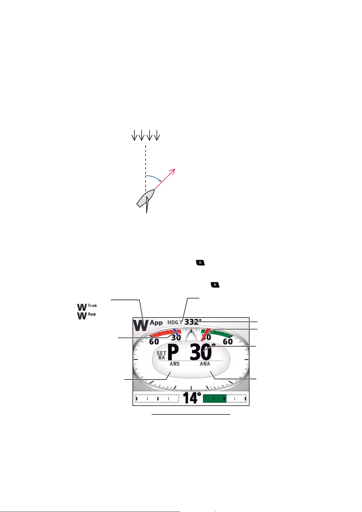
Wind display
The wind display shows wind angle and wind speed. The data can be shown in true
wind or apparent wind. The apparent wind is the actual flow of air acting upon a sail,
or the wind as it appears to the sailor. The true wind is the wind seen by a stationary
observer in velocity and direction. Requires a wind sensor.
Wind mode:
: True
: Apparent
Ship's heading
Set wind angle
(Blue pointer)
Wind speed
90
120
10.2
kn
30.0
120
Wind angle
(Red pointer)
Steering mode data
(See page 1-6.)
90
Wind angle
1-5
Page 18

1. OPERATIONAL OVERVIEW
SETCSE
HDG T
SETCSE
HDG T
Rudder display
The rudder display shows analog and digital rudder angle.
Note: Not available with Fantum Feedback
TM
.
Ship's heading
Steering mode data
HDG T
SETCSE
(See page 1-6.)
Rudder angle/direction
Rudder angle
(Analog)
P: to “port”
S: to “starboard”
Engine speed display
The engine speed display shows the engine revolution. Requires engine speed data.
Ship's heading
HDG T
Engine speed
(Analog)
Engine speed
Steering mode data
(See page 1-6.)
SETCSE
Steering mode data
The table below shows the steering mode data that appears on the graphic display.
Steering mode Display
STBY mode Ship’s heading
AUTO mode Set course
NAV mode
Waypoint course
[NAV mode] = [Course]
NAV mode
Cross-track error
[NAV mode] = [XTE(Precision)] or [XTE(Economy)]
WIND mode Set wind angle
1-6
Page 19

1.5.2 Numerical display
The numerical display provides relevant navigation data according to the steering
mode, on three screens.
1. OPERATIONAL OVERVIEW
㪙
㪘
Type-1 Type-2 Type-3
㪚
㪛
㪝 㪞
㪜
The table below shows the layout and data provided with each steering mode.
Steering mode Layout Display data
STBY mode Type-1 A: Ship’s heading
AUTO mode A: Set course
NAV mode
([NAV mode] = [Course])
NAV mode
([NAV mode] = [XTE(Precision)] or
[XTE(Economy)])
WIND mode Type-3 E: Set wind angle
Type-2 B: Waypoint name
C: Waypoint course
D: Data source
B: Waypoint name
C: Cross-track error
D: Data source
F: Wind speed
G: Wind angle
1-7
Page 20

1. OPERATIONAL OVERVIEW
1.5.3 How to select the display data
You can select the display data to show in the STBY, AUTO, NAV, and WIND modes.
1. Long press the key to open the menu.
2. Rotate the Course control knob to select [Other Menu] then push the knob.
3. Rotate the Course control knob to select [System Setup] then push the knob.
4. Rotate the Course control knob to select [Display Data Select Menu] then push
the knob.
The window as shown below appears.
Display Data Select Menu
STBY
AUTO
NAV
WIND*
*: Sailboats only
5. Rotate the Course control knob to select the steering mode desired then push
the knob.
6. Rotate the Course control knob to select the current setting for display division
desired then push the knob.
Data 1
Data 2
Page 1
Data 1
Data 2 Data 2Data 3 Data 3
Page 2
Data 1
Page 3
Note: Page layout of the page 3 depends on setting of [Data Box Format].
1-8
Page 21

1. OPERATIONAL OVERVIEW
7. Rotate the Course control knob to select display data desired then push the
knob.
The table below shows all the display data available.
Page/Data Data Displayed Data meaning
Graphic / numerical data
Page 1: [Data 1]
Page 2: [Data 1]
Page 3: [Data 1]
[Normal] Numerical display (see section 1.5.2)
[Compass] Compass rose
[Highway] Graphic presentation of progress to-
wards waypoint
[Wind Apparent] Analog and digital apparent wind direc-
tion speed
[Wind True] Analog and digital true wind direction
speed
[Rudder]*
1
Analog and digital rudder angle
[Engine Speed] Analog engine speed (revolution meter)
Analog indicator
Page 1: [Data 2]
Page 2: [Data 2]
Data box
Page 2: [Data 3]
Page 3: [Data 2] / [Data 3]*
[Rudder]*
[Deviation] Heading deviation
[Steering Direc-
tion]*
[POSN] Own ship’s position data
[COG] Course over ground
3
[SOG] Speed over ground
1
Rudder angle
For WIND mode, wind deviation
Steering direction
2
[STW] Speed through water
[Temp] Water temperature
[DPTH] Depth
[BRG] Bearing to waypoint
[RNG] Range to waypoint
[WPT] Waypoint position (Latitude/Longitude)
[XTE] Cross-track error
[TTG] Time-to-go to waypoint
[ETA] Estimated time of arrival to waypoint
[Date] Current date
[Time] Current time
[Wind Apparent] Apparent wind direction/speed
[Wind True] True wind direction/speed
[Volt] Input/output voltage to processor unit
[Trip] Trip distance
[Air Temp] Air temperature
[Atmos Press.] Atmospheric pressure
[Humidity] Humidity
[Dew Point] Dew point
1
*
: Not shown with Fantum FeedbackTM.
2
: Shown with Fantum FeedbackTM.
*
3
*
: Shown when [Data Box Format] = [2Boxes].
8. Push the key several times to close the menu.
1-9
Page 22

1. OPERATIONAL OVERVIEW
1.5.4 How to select the display data with the key operation (STBY mode only)
You can select the display data to show in the STBY mode with the key operation.
1. Short press the key to go to the STBY mode.
2. Press the key again to select a display.
3. Long press the Course control knob.
The item selected by the cursor is circumscribed with a thick rectangle, as in the
illustration below.
Cursor
4. Press the or key to put the cursor on the data to change.
5. Rotate the Course control knob to select the display data then push the knob.
1-10
Page 23

2. STEERING MODES
This chapter describes the steering modes and functions of the NAVpilot.
2.1 STBY Mode
After turning on the power, the equipment goes to the STBY mode. This is a manual
steering mode. When sailing into or out of a harbor, steer the vessel in the STBY mode
by using the steering wheel (helm) of your boat. In the STBY mode, “STBY“ appears
on the display.
The compass rotates to keep the ship’s heading (gray pointer) at the top of the display.
Steering mode
Heading mode
T: True
M: Magnetic
Ship's heading
(Gray pointer)
Ship's heading
Analog indicator
or data box
2.2 AUTO Mode
The AUTO mode steers the boat automatically on a course set by the operator.
The AUTO mode will not compensate for the effects of wind or tide, which can push
you off course athwart in the ship direction. Use the AUTO mode for short, straight
voyages. Otherwise switch to the NAV mode (see section 2.3).
Tide and Wind Tide and Wind Tide and Wind
Display example: STBY mode
2-1
Page 24

2. STEERING MODES
SETCSE
2.2.1 How to get the AUTO mode
To get the AUTO mode, do as follows:
1. Direct the boat toward required course.
2. Press the AUTO key to activate the AUTO mode.
Your boat automatically maintains the current course when the AUTO key is
pressed. When the heading changes from the set course, the NAVpilot automatically adjusts the rudder to return the boat to the set course.
In the AUTO mode, the steering indication at the top left corner of the display
shows “A“.
The compass rotates to keep the ship’s heading (gray pointer) at the top of the
display.
Steering mode
Ship's heading
(Gray pointer)
Set course / waypoint cource
SETCSE
(Red pointer)
Set course
Heading mode
T: True
M: Magnetic
Display example: AUTO mode
3. To change the course setting in the AUTO mode, rotate the Course control knob
to the required course.
4. To exit the AUTO mode to steer manually, press the key. Steer your boat by
the helm.
Analog indicator
or data box
2-2
Page 25

2.2.2 Advanced AUTO mode
㪘
㪘㪻㫍
The AUTO mode keeps a set course, but your boat’s course can change by the effects
of tide and wind. To adjust for the effects of tide and wind, use the Advanced AUTO
mode. The NAVpilot calculates your course according to your current position and
heading, then sets a virtual "waypoint" in its memory to navigate towards. If either tide
or wind begins to push you off course, the NAVpilot corrects your heading accordingly.
For use of the Advanced AUTO mode, connect a GPS navigator which outputs position data (Latitude and Longitude) to the NAVpilot.
2. STEERING MODES
Tide and Wind
To get the Advanced AUTO mode, do as follows:
1. In the AUTO mode, long press the key to show the menu.
2. Rotate the Course control knob to select the current setting for [Advanced AUTO] then push the knob.
[Advanced AUTO] also appears on the [AUTO Option] menu.
3. Rotate the Course control knob to select [ON] then push the knob. The steering
indication at the top left corner of the display changes as below. Select [OFF] to
quit the Advanced AUTO mode.
Tide and Wind
OFF
ON
Tide and Wind
㪘㪻㫍
㪘
Note: When the position data is not input, the pop-up message “No Position Data“
appears and audio alarm sounds. Press any key to stop the alarm, then confirm
the connection with the GPS navigator.
4. Press the key to close the menu.
You can switch between AUTO and Advanced AUTO modes by holding down the
AUTO key three seconds to show the message "Advanced AUTO ON (OFF)".
Note: How strictly the Advanced AUTO mode keeps the course depends on the [NAV
Mode] setting in the [NAV Option] menu.
[NAV Mode] setting
• [Course] and [XTE(Economy)]
• [XTE(Precision)]
Keeps the course within 0.03 NM.
:
: Keeps the course within 0.01 NM.
2-3
Page 26

2. STEERING MODES
2.3 NAV Mode
NAVpilot steers the vessel towards the current waypoint while compensating for the
effects of tide and wind.
When connected to a GPS navigator, NAVpilot steers the vessel to follow a series of
waypoints in sequence. When you arrive at each waypoint or destination, audible and
visual alerts are activated.
The NAVpilot takes 15 seconds to activate the NAV mode after the NAVpilot receives
the destination information.
Waypoint Waypoint Waypoint
Tide and Wind Tide and Wind
Steering to a single waypoint
Waypoint Waypoint
Steering a route (a series of waypoints)
Tide and Wind
2-4
Page 27

2.3.1 How to get the NAV mode
HDG T
To get the NAV mode, do as follows:
1. Set the destination waypoint (or route) on the GPS navigator or chartplotter.
To navigate a route, make sure that your plotter is navigating towards the nearest
or required waypoint before you put the NAVpilot into the NAV mode.
2. Manually steer the boat toward the waypoint.
3. Press the NAV key.
You are asked if you are sure to navigate to the waypoint selected.
4. Push the Control course knob to start to navigate to the waypoint.
Steering mode
㪑㩷[NAV Mode] = [Course]
㪑㩷[NAV Mode] = [XTE (Precision)]
㪑㩷[NAV Mode] = [XTE (Economy)]
HDG T
Ship's heading
Waypoint mark
Own ship mark
2. STEERING MODES
Waypoint name
Direction to next waypoint
(Turn to STBD)(Turn to PORT)
Set course or
XTE value
Data source
Analog indicator
or data box
Display example: NAV mode
Note: The course reading on the NAVpilot is not always the same as the waypoint direction shown on the chartplotter.
You can switch between nav data sources (for example, one source fails) by pressing
the NAV key three seconds. This feature is not available when [NAV Data Source] is
set to [Both] (at installation).
2-5
Page 28

2. STEERING MODES
2.3.2 Sailing method for the NAV mode
Your vessel can go off course between waypoints in the NAV mode. This can occur
when, for example, a command is received from a remote controller. To return to the
course set, three methods are available: [Course], [XTE (Precision)], and [XTE (Economy)].
• [Course]: The NAVpilot calculates a new course according to your new position (after dodging, etc.) that takes you directly to your destination waypoint.
• [XTE (Precision)] and [XTE (Economy)]: The NAVpilot uses the XTE (cross-track error) value to steer the boat towards your ORIGINAL course before dodging. [XTE
(Precision)] provides for tighter course keeping, within 0.01 NM of the set course.
[XTE (Economy)] gives less tighter course keeping, within 0.03 NM of the set
course.
Note: [Course] is not available with Fantum Feedback
TM
.
Course line
([NAV Mode] = [Course])
Waypoint
Original course
XTE line
([NAV Mode] = [XTE(Precision)] or [XTE(Economy)])
Select the sailing method as shown below.
1. In the NAV mode, long press the key to show the menu.
2. Rotate the Course control knob to select the current setting for [NAV Mode] then
push the knob.
[NAV Mode] also appears on the [NAV Option] menu.
Course*
XTE (Precision)
XTE (Economy)
2-6
TM
*: Not shown with Fantum Feedback
.
3. Rotate the Course control knob to select an option then push the knob.
4. Press the key to close the menu.
Page 29

2.3.3 Waypoint switching method
When you arrive at a waypoint on a route in the NAV mode, you can switch to the next
waypoint automatically or manually.
Select waypoint switching method as follows:
1. In the NAV mode, long press the key to show the menu.
2. Rotate the Course control knob to select the current setting for [Waypoint
Switching] then push the knob.
[Waypoint Switching] also appears on the [NAV Option] menu.
Auto
Manual
3. Rotate the Course control knob to select an option then push the knob.
[Auto]: Switches to the next destination waypoint when your boat is within the ar-
rival alarm area (set on the chartplotter). When your boat is within the arrival alarm
area, the buzzer sounds for five seconds and the message "WPT was changed."
appears.
[Manual]: Requires operator confirmation (pushing the Course control knob) before switching to the next waypoint. For manual switching, the NAVpilot sounds a
five-second alarm when the vessel arrives at the destination waypoint. The message "Push any key to return." appears. Push any key. Then, the message “WPT
was changed.” appears.
2. STEERING MODES
4. Press the key to close the menu.
2-7
Page 30

2. STEERING MODES
2.3.4 How to set the steering behavior of your boat after you arrive to a waypoint
When you arrive to the last waypoint in a route, the FishHunterTM mode can be acti-
TM
vated automatically to steer the boat according to the FishHunter
details of each preset, see section 2.6.
This function is not available with a sailboat.
mode preset. For
To enable the FishHunter
TM
mode and set the steering behavior, do as follows:
1. In the NAV mode, long press the key to show the menu.
2. Rotate the Course control knob to select the current set-
ting for [After Arrival] then push the knob.
[After Arrival] also appears on the [NAV Option] menu.
For Fantum Feedback
TM
, only [GO Straight] and [Orbit to
STBD] appear.
• [GO Straight]: Cruise straight after arriving at the last
GO Straight
Orbit to PORT
Orbit to STBD
Figure Eight PORT
Figure Eight STBD
Square PORT
Square STBD
waypoint.
• [Orbit to PORT]: Orbits to PORT around waypoint.
• [Orbit to STBD]: Orbits to STBD around waypoint.
• [Figure Eight PORT]: Turns to PORT in a figure-eight pattern.
• [Figure Eight STBD]: Turns to STBD in a figure-eight pattern.
• [Square PORT]: Turns to PORT in a square pattern.
• [Square STBD]: Turns to STBD in a square pattern.
3. Rotate the Course control knob to select an option then push the knob.
4. Press the key to close the menu.
2-8
Page 31

2.4 Response Feature
The response feature provides for simple setting of the NAVpilot’s parameter to
counter the effects of wind, etc. Normally, use the auto response feature (see
section 2.4.1). If you feel that the auto response feature is not working properly, adjust
the response feature manually (see section 2.4.2). This feature is available in the following conditions:
• AUTO, NAV, WIND modes
• [Sea State] is set for [Full-Auto] or [Semi-Auto]. For the setting of [Sea State], see
section 4.1.1.
2.4.1 How to activate the auto response feature
1. Push the Course control knob to show the [Response] window.
2. Press the key to select [Auto].
Response
2. STEERING MODES
Auto
Push ENTER knob
To return
3
3. Push the Course control knob to confirm your setting and close the window.
2.4.2 How to activate the manual response feature
1. Push the Course control knob to show the [Response] window.
2. Press the key to select the current setting value.
Response
Auto
Turn the knob
to change value.
3. Rotate the Course control knob to set response level (setting range: 1-9).
Raise the response level to get back on course when external interference (wind,
etc.) is pushing the boat off course.
4. Push the Course control knob to close the window.
3
2-9
Page 32

2. STEERING MODES
5
2.5 TURN Mode
The TURN mode has two types: normal turn and FishHunterTM mode turn. For Fish-
TM
Hunter
Note 1: Turn mode is not available with a sailboat.
Note 2: FishHunterTM mode turn is not available with Fantum FeedbackTM.
2.5.1 How to select a normal turn and start the turn
The normal turn provides three preset turning motions: 180°, 360°, and user turn.
These turns are available in the AUTO and NAV mode and in clockwise and counter
clockwise directions.
Select the 180°, 360°, or user turn as follows:
1. Press the key to show the turn menu.
mode turn, see section 2.6.
㪧
㪧
Orbit Turn
Turn 180° to STBD
Push to ENTER
Rotate to choice
2. Rotate the Course control knob to select a turn.
The cursor highlights current selection. See section 2.5.2 and section 2.6.1 for description of turns.
㪪
㪈㪏㪇㪈㪏㪇
㪧
㪊㪍㪇
180° Turn 360° Turn
㪊㪍㪇
㪪
㪧
User Turn
(Defaut setting: 45°)
㪧
㪪
Spiral Turn
㪪
㪧
Figure 8 Turn
Note 1: You can set the parameters for the user turn (before starting the turn) by
pressing the key. For details, see "User turn" on page 2-12.
Note 2: Only 180°, 360°, and user turn are available with Fantum Feedback
㪧
㪪
㪪
Circle Turn
㪪
㪧
㪪
Square Turn Zigzag Turn
TM
.
2-10
Page 33

3. Push the Course control knob to start the turn.
Ship mark
Turn starting marker
(Points to 0°.)
After you start the turn, the message "Beginning turn" appears, and the alarm sounds
three times.
During the turn, the ship mark, which indicates own ship’s course movement, appears
on the turn display. The ship mark does not show accurate ship’s movement.
Turn starting marker
(Points to 0°.)
2. STEERING MODES
Ship mark
When the turn starts
After the turn is completed, the message "Turn ended" appears, and the alarm
sounds three times.
2.5.2 Types of normal turns
180° turn
This function changes the current set course by 180° in
the opposite direction. This feature is very useful in a man
overboard situation and whenever you want to steer back
on a reciprocal heading.
360° turn
During the turn
Turn end marker
(Points to turn angle.)
When the turn ends
This function also provides a continuous turn feature with
a constant rate of turn in a circle. This feature is useful in
purse seining.
2-11
Page 34

2. STEERING MODES
45°
User turn
You can set desired turn angle with this turn, from 15° to 360° in 15° degree increments.
1. Press the key to show the turn menu.
2. Rotate the Course control knob to select the user turn icon.
㪧
or
User turn icon
㪪
3. Press the key to set the turn angle for the user turn.
Turn of User Setting Data
Turn Angle: 45
Run
4. The cursor is selecting the value for [Turn Angle]; push the Course control knob.
The turn angle of the user turn can also be set at [System Setup] menu.
5. Rotate the Course control knob to select the turn angle (setting range: 15° to
360°).
6. To start the turn, rotate the Course control knob to select [Run] then push the
knob.
2-12
Page 35

2. STEERING MODES
5
2.6 FishHunter
TM
Mode
The FishHunterTM mode is a unique feature of FURUNO NAVpilot series. Find a fish
target with your FURUNO sonar/sounder or bird target with your FURUNO radar and
feed it to the NAVpilot. The NAVpilot will activate the FishHunter
TM
mode to perform
circle, orbit, spiral, figure eight, square or zigzag maneuvers around the specified target.
Note: This function is not available with a sailboat or Fantum Feedback
2.6.1 How to select a FishHunterTM turn and start the turn
1. Press the key to show the turn menu.
Turn 180° to STBD
Push to ENTER
Rotate to choice
TM
.
㪧
㪧
Orbit Turn
TM
2. Rotate the Course control knob to select a FishHunter
turn. The cursor high-
lights current selection.
㪪
㪈㪏㪇㪈㪏㪇
㪧
㪊㪍㪇
180° Turn 360° Turn
㪊㪍㪇
㪪
㪧
User Turn
㪧
㪪
㪪
Circle Turn
(Defaut setting: 45°)
㪧
㪪
Spiral Turn
㪪
㪧
Figure 8 Turn
㪪
㪧
Square Turn Zigzag Turn
㪪
3. If you want to change the parameters for the turn, do 1) - 3) below. If you do not
need to change the parameters, go to step 4.
1) Press the key to the show the setting menu for the turn. See section 2.6.3
for details.
2) Rotate the Course control knob to select the current setting value for the pa-
rameter then push the knob.
3) Rotate the Course control knob to set a value then push the knob.
4) Select [Run] then push the knob to start the turn.
2-13
Page 36

2. STEERING MODES
Ship mark
Ship mark
Radius
䋨
See section 2.6.3.
䋩
4. Push the Course control knob to start the turn.
The message “Start to turn by fishing mode“ appears, then your boat starts the
turn selected.
Note: The orbit and spiral turns require that the speed of the boat be less than 10
kn. If the speed is higher, the message "Too fast to go fishing mode." appears.
Reduce boat's speed to less than 10 kn.
During the turn, the ship mark, which indicates own ship’s course movement, appears
on the turn display. The ship mark does not show accurate ship’s movement. To quit
the turn, press the key.
After the turn is completed, the message "Turn ended." appears.
Circle turn
Ship mark
Orbit turn
Radius
See section 2.6.3.
䋨
The rate of turn
See section 2.6.3.
䋨
Ship mark
䋩
䋩
2-14
Page 37

2. STEERING MODES
Ship mark
Radius
䋨
See section 2.6.3.
䋩
Speed
䋨
See section 2.6.3.
䋩
Radius
䋨
See section 2.6.3.
䋩
Ship mark
Turn angle
䋨
See section 2.6.3.
䋩
Ship mark
Turning line
䋨
See section 2.6.3.
䋩
Spiral turn
Ship mark
Speed
See section 2.6.3.
Radius
See section 2.6.3.
䋨
䋨
䋩
䋩
When you select the spiral turn while in the NAV mode or from the TLL menu (see
section 2.7), the waypoint name and NAV or TLL icon appears.
Waypoint name
NAV icon
When the turn is selected in the NAV mode
Figure-eight turn
Radius
See section 2.6.3.
䋨
䋩
Square turn
Waypoint name
TLL icon
When the turn is selected from the TLL menu
Ship mark
Ship mark
Turn angle
See section 2.6.3.
Turning line
See section 2.6.3.
䋨
䋨
䋩
㩷
䋩
2-15
Page 38
2. STEERING MODES
Turn angle
䋨
See section 2.6.3.
䋩
Ship mark
Termination condition
䋨
See section 2.6.3.
䋩
Turn width
䋨
See section 2.6.3.
䋩
Zigzag turn
Ship mark
Turn angle
See section 2.6.3.
䋨
Turn width
See section 2.6.3.
䋨
䋩
䋩
When you select the zigzag turn while in the NAV mode or from the TLL menu (see
section 2.7), the waypoint name and NAV or TLL icon appears instead of the termination condition.
Waypoint name
NAV icon
When the turn is selected in the NAV mode
When the turn is selected from the TLL menu
2.6.2 Types of FishHunterTM turns
Circle turn
Termination condition
See section 2.6.3.
䋨
䋩
Waypoint name
TLL icon
The circle turn can be used for circling fish or a particular object on the seabed. The
rate of turn for the circle can be selected from the menu, but it cannot be higher than
that set at installation. This turn can be affected by tide and wind.
Specified turn rate
Heading
Bow direction
2-16
Page 39

2. STEERING MODES
Orbit turn
In the AUTO mode, your boat orbits around its current position. For the NAV mode,
the boat orbits around the (last) waypoint. This function requires a chartplotter or GPS
navigator.
Radius
(set on the menu)
Spiral turn
The boat spirals in the direction of current heading (STBY), set course (AUTO) or the
course to the next waypoint (NAV) that was active at the moment that the spiral turn
is started.
The boat will continue to spiral until the or AUTO key is pressed.
Radius (set on the menu)
Distance between spiral centers
Distance between spiral centers (NM)
䋽
6.28 × Radius
Speed (set on the menu)
Note: In the NAV mode, if the boat does not enter the arrival alarm area, the NAVpilot
does not switch to the next waypoint. To prevent this, set the arrival alarm range as
large as possible and activate the perpendicular function on the chartplotter.
2-17
Page 40

2. STEERING MODES
Figure-eight turn
After the boat has traveled the radius set on the menu, it starts turning in a figure-eight
pattern, automatically returning to the position where the figure-eight was initiated.
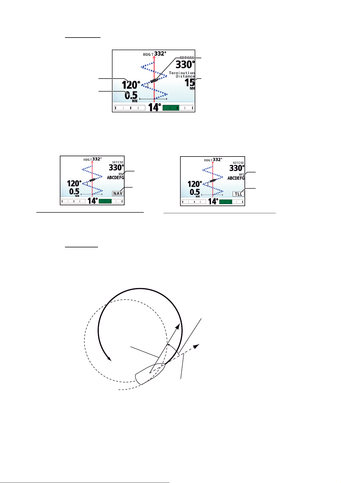
The radius is set on the menu.
Radius (set on the menu)
Square turn
The square turn is started from a waypoint. You can set length of the sides and the
azimuth on the menu.
N
Corner
Turning point
Turn angle
(set on the menu)
Center
2-18
Turning line (set on the menu)
Page 41

2. STEERING MODES
Turn angle
Turn angle
Zigzag turn
The zigzag turn starts from current position. The distance between legs, turn angle,
number of turns and how to stop the zigzag turn can be set on the menu. This turn is
available in the AUTO and NAV modes.
N
2nd turn
Turn angle
Turn angle
4th turn
6th turn
Width
1st turn
Distance
3rd turn
Turn angle
Turn angle
7th turn
5th turn
Number of turns
(set on the menu)
2-19
Page 42

2. STEERING MODES
2.6.3 How to set FishHunter
You can set the parameters for the FishHunterTM turns as follows:
1. Long press the key to open the menu.
2. Rotate the Course control knob to select [Other Menu] then push the knob.
3. Rotate the Course control knob to select [Fish Hunter Option] then push the
knob.
Circle
Orbit
Spiral
Figure8
Square Turn
4. Rotate the Course control knob to select the turn desired then push the knob.
Set the parameters for each turn referring to the figure bellow.
Rate of Turn: 3 °/s
TM
turn parameters
Fish Hunter Option
Circle
<Setting range>
1°-30°/s
Rate of turn cannot be higher
than that set at installation
Fish Hunter Option
Circle
Orbit
Spiral
Figure 8
Square Turn
Zigzag
Orbit
Radius: 0.05 NM
SPIRAL
Speed: 0.5 kn
Radius: 0.05 NM
Figure 8
Radius: 0.05 NM
Square Turn
Side Length: 1.0 NM
Azimuth: Auto
Auto
Manual
Zigzag
Turn Angle: 90 °
Termination: Continuous
Distance:
Number of Turns:
Width: 0.5 NM
0.05-9.99 NM
[Speed]: 0.1-2.0 kn
[Radius]: 0.05-9.99 NM
0.05-9.99 NM
[Side Length]: 1.0-9.9 NM
[Azimuth]: 0-359° ([Manual])
[Turn Angle]: 30°-150°
[Number of Turns]: 1-20
([Termination] = [Number of Turns])
[Distance]: 1-99 NM
([Termination] = [Distance])
[Width]: 0.1-9.9 NM
2-20
Number of Turns
Distance
Continuous
Page 43

2.7 How to Navigate to a TLL Position
The moment TLL (Target Latitude and Longitude) data is input from a radar or echo
sounder in the STBY, AUTO or NAV mode, a dialog box appears, where you can select how to progress towards that position. This mode requires position data and waypoint position data.
When the TLL data is input, the TLL menu as shown below appears. Rotate the
Course control knob to select the turn. You can quit the turn but you can not change
the turn mode.
Note: This mode is not available with a sailboat.
Options on the TLL menu
2. STEERING MODES
Push to ENTER
Rotate to choice
TLL menu
CANCEL
NAV
㪧
Spiral
Turn to
PORT
Not shown with Fantum FeedbackTM.
㪪
Spiral
Turn to
STBD
Zigzag
Turn
• [CANCEL]: Continues current steering mode.
• [NAV]: The boat goes to the TLL by the NAV mode. When [NAV] is selected, the steering mode indication at the top left corner of the display
changes as shown right.
• [Spiral Turn to PORT (or STBD)]: The boat goes to the TLL point in a spiral pattern. The waypoint name and TLL icon appear on the turn display.
Waypoint name
TLL icon
• [Zigzag Turn]: The boat follows a zigzag pattern to the TLL. The waypoint name
and TLL icon appear on the turn display instead of the termination condition.
Waypoint name
TLL icon
2-21
Page 44

2. STEERING MODES
2.8 DODGE Mode
The DODGE mode is useful in situations where you need to quickly take control of the
helm to avoid an obstruction.
To use the DODGE mode, set [Arrow Key] to [Dodge] on the [System Setup] menu.
2.8.1 How to dodge in the AUTO and NAV modes
Press the or key down to steer appropriately until the boat has cleared the
obstruction. The equipment goes into the DODGE mode and the audible alarm sounds
when one of the above keys is operated, to alert you to dodge operation. Note also
that " " appears at the top left corner of the display. To quit the DODGE
mode, release the or key.
2.8.2 How to FU dodge in the STBY mode
Press the or key simultaneously to steer appropriately until the boat has
cleared the obstruction. The equipment goes into the FU mode, and " " appears
at the top left corner of the display. Rotate the Course control knob to set the course.
To escape from the FU mode, press the key.
Note: FU dodge mode is not available with Fantum Feedback
2.8.3 How to NFU dodge in the STBY mode
Non-Follow up (NFU) is a manual steering mode that moves the rudder as long as the
or key is operated. At this time, " " appears at the top left corner of the
display. To quit the NFU mode, release the key.
TM
.
2-22
Page 45

2.9 REMOTE Mode
Four types of optional remote controllers can be connected to your NAVpilot to control
the NAVpilot from a remote location.
The REMOTE mode is available in the AUTO or NAV mode.
To use the REMOTE mode, select the mode of the remote controllers from the [RC
Setup] menu (see section 7.17).
2. STEERING MODES
Note: Remote controllers are not available with Fantum Feedback
2.9.1 Dial-type remote controller (FAP-5551, FAP-5552)
These are FU-type remote controllers, and they can be used in the AUTO and NAV
modes. The rudder moves until operation of the remote controller is stopped.
To use this function, set the remote mode of the remote controllers to [FU] on the [RC
Setup] menu (see section 7.17).
1. Turn the switch on the remote controller to show
" " on the control unit.
Note: When the remote controller switch is turned on,
the controls other than the and keys are inoperative.
2. Rotate the dial on the remote controller to set the rudder
angle.
TM
.
3. To turn off the REMOTE mode, turn off the remote
controller.
Control is returned to the main control unit and the mode that was previously active
(AUTO or NAV) is restored. For the NAV mode, the boat will go to the destination waypoint based on the nav steering method menu setting (see section 2.3.2).
2-23
Page 46

2. STEERING MODES
2.9.2 Button-type remote controller (FAP-6211, FAP-6212), Lever-type remote controller (FAP-6221, FAP-6222)
The button-type and lever-type controller has an ON/OFF switch and works like an
NFU remote controller. When the remote controller is turned on, the user operates the
remote controller to move the rudder and the rudder stops once operation of the remove controller is stopped.
To use this function, set the remote mode of the remote controllers to [NFU] on the
[RC Setup] menu (see section 7.17). For the button-type remote controller, you can
use as the dodge-type remote controller when the remote mode is set to [Dodge].
1. Turn on the remote controller to show " " on the control unit.
ON䋺 Switch to ON
ON䋺Pull the lever.
Button-type
Lever-type
2. For button-type remote controllers, press the W or X key on the remote controller.
For the lever-type, position the lever for the direction.
Turn to PORT
Button-type
Turn to STBD
Turn to PORT Turn to STBD
Lever-type
2-24
Page 47

2. STEERING MODES
3. Turn off the remote controller to terminate the REMOTE mode.
OFF䋺 Switch to OFF
OFF䋺Pull the lever.
Button-type
Lever-type
2.9.3 Dodge-type remote controller (FAP-6231, FAP-6232)
The dodge-type remote controller does not have a power switch.
Operate it by simply pressing the direction buttons. The dodgetype remote controller sets your course and rudder is moved to
PORT
STBD
steer the set course.
The dodge-type controller can be used in the AUTO and NAV
mode. While you operate the dodge-type controller,
“ “ appears on the controller unit.
To use this function, set the remote mode of the remote controllers to [Dodge] on the [RC Setup] menu (see section 7.17).
2-25
Page 48
2. STEERING MODES
S
30.0°
10.2
kn
9 0
9 0
1 2 0
1 2 0
2.10 WIND Mode (for sailboats)
In the WIND mode, the NAVpilot steers the boat based on the wind angle. The NAVpilot consistently maintains the preset angle between ship’s heading and wind direction
(true or apparent), while eliminating the effects of turbulence and short term wind variations.
To use the WIND mode, set [Boat Type] to [Sailboat] on the [Ship’s Characteristics]
menu. Also, the wind sensor data is required.
Note: The WIND mode is not available with Fantum Feedback
Wind
(True or apparent)
Wind angle
(True or apparent)
Heading
TM
.
2.10.1 How to get the WIND mode
1. Direct the heading to the desired direction and trim the sail to keep the wind direc-
tion, in the STBY mode.
2. Press the AUTO key while holding the key down to activate the WIND mode.
3. Rotate the Course control knob to set the wind angle.
4. To escape from the WIND mode, press the key.
Wind mode:
: True
: Apparent
Set wind angle
(Blue pointer)
90
10.2
Wind speed
120
kn
Heading mode
T: True
M: Magnetic
90
30.0
120
Heading
Wind angle
(Red pointer)
Set wind angle
Wind angle
2-26
Display example: Wind mode
Page 49

2.10.2 Wind angle mode
W
App
W
TWA
There are two wind angle modes: App (Apparent Wind Angle) and TWA (True Wind
Angle).
2. STEERING MODES
Wind angle
mode
App
(Apparent
Win Angle)
TWA
(True Wind
Angle)
N
Boat's
heading
Description
The boat is steered so that the apparent wind angle
is constant. AWA mode requires wind angle and
speed data from a wind sensor. Use this mode when
the wind is stable.
The boat is steered so that the true wind angle (in relation to ship’s bow) is constant. This mode requires
apparent wind angle, apparent wind speed, your
boat's speed and heading. Use this mode when
there is an unstable downwind.
True wind angle
True wind
Own boat's
movement
Apparent wind
NOTICE
Steering mode
indication
App
W
TWA
W
When running on engine, use
Apparent wind angle
To select the wind angle mode, do the following:
1. In the Wind mode, long press the key to open the menu.
2. Rotate the Course control knob to select the current setting for [Mode Type] then
push the knob.
[Mode Type] also appears on the [Wind Option] menu.
AWA
TWA
3. Rotate the Course control knob to select an option then push the knob.
4. Press the key to close the menu.
the TWA mode.
The autopilot cannot control your
boat when its speed exceeds the
true wind speed in the App mode,
which can lead to a potentially
dangerous situation.
2-27
Page 50

2. STEERING MODES
2
A
2.10.3 TACK mode
The TACK mode provides various tacking and gybing motions. Fixed and auto tacking
are available. Use the tack mode when the true wind angle is less than 90°.
Tacking/gybing (fixed tack)
This function changes the current course by the degrees (set on menu) to port or starboard direction. There are two types of speed, [Slow] (for gybing) and [Fast] (for tacking) in this mode.
To start tacking/gybing, do the following:
1. Press the AUTO key to get the AUTO mode.
2. Press the key to show the turn menu.
The tack angle depends on the value of [Fixed Tack Angle]. For how to set [Fixed
Tack Angle], see "How to set the fixed tack angle" on page 2-30).
HDG T
HDG T 0°
SETCSE 19
°
Slow Turn to PORT
Tack Angle : 100°
Push to ENTER
Rotate to choice
The value of [Fixed Turn Angle]
3. Rotate the Course control knob to select a turn.
[Slow Turn to Port (STBD)]: For gybing, when the
PS
wind angle is larger than 120°. The boat slowly
changes the heading angle.
[Fast Turn to PORT (STBD)]: For tacking, when
P
S
the true wind angle is less than 90°. The boat rapidly
changes the heading angle.
Gybing
Tacking
Wind direction
2-28
Wind direction
Degrees set on Rate of Slow Tack
Slow mode (Rudder to starboard)
Degrees set on Rate of Fast Tack
Fast mode (Rudder to starboard)
Page 51

2. STEERING MODES
Ship mark
Turn starting marker
(Points the angle when
the turn started.)
4. Push the Course control knob to start the turn.
After you start the turn, the message "Beginning turn" appears, and the alarm
sounds three times.
5. While confirming your heading, do jib sheet creasing and trimming operations.
Your boat starts turning in the direction selected at step 3.
During the turn, the ship mark, which indicates own ship’s course movement, appears on the turn display. The ship mark does not show accurate ship’s movement.
Turn starting marker
(Points the angle when
the turn started.)
Ship mark
When the turning is completed, a beep sounds three times and the message "Turn
ended" appears.
• The tacking angle can be set on the menu. See "How to set the fixed tack
angle" on page 2-30.
• The amount of the time to wait before starting a turn after pushing the Course con-
trol knob can be set on the menu. See "How to set the tack timer" on page 2-33.
How to set the rate of turn for Fast and Slow tacking
The rate of turn is preset as 3° for [Slow Turn to PORT (or STBD)] and 20° for [Fast
Turn to PORT (or STBD)]. If you need to change the value, do the following:
1. In the WIND mode, long press the key to open the menu.
2. Rotate the Course control knob to select the current setting value for [Rate of
Slow (Fast) Tack] then push the knob.
[Rate of Slow (Fast) Tack] also appears on the [Wind Option] menu.
When the turn starts
During the turn
Turn end marker
(Points the angle when
the turn will end.)
When the turn ended
3. Rotate the Course control knob to set the rate then push the knob.
4. Press the key to close the menu.
2-29
Page 52

2. STEERING MODES
How to set the fixed tack angle
The fixed tacking mode requires the setting of tacking angle. Set the angle as follows:
1. In the WIND mode, long press the key to open the menu.
2. Rotate the Course control knob to select the current setting value for [Fixed Tack
Angle] then push the knob.
[Fixed Tack Angle] also appears on the [Wind Option] menu.
3. Rotate the Course control knob to set the angle then push the knob (setting
range: 15°-179°).
4. Press the key to close the menu.
2.10.4 Tacking in WIND mode (WIND TACK)
In the WIND mode, the degree and direction of tacking are automatically set so that
the boat receives the apparent wind on its opposite side with the same angle.
Wind direction
"
"
To start turning, do the following:
1. In the WIND mode, press the key to show the Turn menu.
2. Rotate the Course control knob to select the direction to turn.
The selections are “Turn to PORT” and “Turn to STBD”. If you select an unavailable direction, the message "Wind dir is out of range for your choice" appears and
the selection is refused.
2-30
Page 53

2. STEERING MODES
Turn end marker
(Points the angle when
the turn will end.)
Ship mark
Turn starting marker
(Points the angle when
the turn started.)
The turning direction is determined according to the heading at the time the key is
pressed, as shown below.
㪪㪫㪙㪛
㪧㪦㪩㪫
15°
Wind direction
10°
15°
: Direction
available to turn
㪧㪦㪩㪫
15°
When the boat is in this
area, it may be turned
in either direction.
㪪㪫㪙㪛
3. Push the Course control knob to start the turn.
The boat starts turning toward the selected direction until the heading changes
twice that set when the Course control knob was pressed. After you start the
turn, the message "Beginning turn" appears, and the alarm sounds three times.
During the turn, the ship mark, which indicates own ship’s course movement, appears on the turn display. The ship mark does not show accurate ship’s movement.
Turn starting marker
(Points the angle when
the turn started.)
Ship mark
When the boat is in this area,
it cannot be turned in either direction.
When the turn starts
During the turn
Turn reference marker
(Points the middle angle
between the turn starting and
turn end marker.)
Turn end marker
(Points the angle when
the turn will end.)
When the turn ends
The amount of the time to wait before starting a turn after selecting the turn from
the turn menu can be set on the menu. See "How to set the tack timer" on page 2-
33.
When the turning is completed, a beep sounds three times and the message "Turn
ended" appears.
2-31
Page 54

2. STEERING MODES
How to set maximum rudder angle for wind tacking
The tacking in the WIND mode requires the setting of maximum rudder angle. This angle is calculated automatically when the NAVpilot is installed. If you need to change
the value, do the following:
1. Long press the key to open the menu.
2. Rotate the Course control knob to select the current setting value for [Wind Track
Rud Angle] then push the knob.
[Wind Track Rud Angle] also appears on the [Wind Option] menu.
3. Rotate the Course control knob to set the angle then push the knob.
4. Press the key to three times close the menu.
How to set the damping interval for wind data
You can set the damping interval for wind data to compensate for random fluctuation
in wind data. The higher the setting the more “smooth” the data. However, a high
damping interval causes delay in receiving wind data; the amount of delay equivalent
to the damping interval. Turn off wind damping if the wind data is received stably.
The port and starboard wind angles must be 55° or higher and the [Mode Type] must
be selected to [TWA] (see section 2.10.2) to use this function.
1. Long press the key to open the menu.
2. Rotate the Course control knob to select the current setting for [Wind Damping]
then push the knob.
[Wind Damping] also appears on the [Wind Option] menu.
3. Rotate the Course control knob to select [ON] then push the knob.
4. Rotate the Course control knob to select the current wind damping interval then
push the knob.
5. Rotate the Course control knob to set the interval then push the knob (setting
range: 0.7 - 99 sec.).
See the table below for wind angle and wind damping interval.
Wind damping (s)
User
setting
1.0
2-32
0 55.0 70.0 180.0 (°)
6. Press the key to close the menu.
Wind angle
Page 55

2. STEERING MODES
How to set the tack timer
You can set the amount of time to wait before starting
a turn (tack time), after selecting the turn from the turn
menu. When you enable the tack timer, the countdown
Tack starts after
10 Seconds
window shown right appears after selecting the turn
from the turn menu.
Setting value of the tack timer
1. In the WIND mode, long press the key to open the menu.
2. Rotate the Course control knob to select the current setting for [Tack Timer] then
push the knob to show the tack timer options.
[Tack Timer] also appears on the [Wind Option] menu.
3. Rotate the Course control knob to select [ON] then push the knob.
4. Rotate the Course control knob to select the current timer value then push the
knob.
5. Rotate the Course control knob to set the timer value then push the knob (setting
range: 1 - 99 sec.).
6. Press the key to close the menu.
2-33
Page 56

2. STEERING MODES
2.11 OVRD mode (for IPS drive)
When the IPS drive controls the rudder, the OVRD (override) mode is automatically
enabled. The autopilot can not control the vessel in the OVRD mode.
Note: The OVRD mode is enabled for
OVRD mode activation in the STBY mode
When the OVRD mode activates in the STBY mode, [OVRD] appears at the top-left
position of the display. At this time only the [Installation Menu] window and user menus
are operative. When the IPS drive releases control of the rudder, the autopilot goes to
the STBY mode.
HDG
T
359
OVRD mode activation in the AUTO or NAV mode
°
When the IPS drive releases
control of the rudder.
the IPS drive equipped vessel only.
T
359
°
When the OVRD mode activates in the AUTO or NAV mode, the audio alarm sounds,
the message “EVC Override” appears, and the mode indication at the top-left position
of the display shows [OVRD]. Press any key to stop the alarm and erase the pop-up.
When the IPS drive releases control of the rudder, the autopilot goes to the STBY
mode.
HDG
EVC Override
T
359°
T
Press any key.
HDG
359°
When the IPS drive releases
control of the rudder.
T
359°
2-34
Page 57

2.12 Safe Helm Mode
SETCSE
The safe helm mode, available with the Accu-Steer FPS 12V/24V drive unit, temporarily switches the NAVpilot to manual steering for the specified time interval when the
helm is steered in an automatic steering mode (AUTO, NAV, etc.). This prevents continued turning of the helm. The mode and course indications flash when the safe helm
mode activates.
The safe helm mode is deactivated and the previous automatic steering mode is restored in the following situations:
NAV mode: When the data from helm sensor is not input for the set time on [Return
Delay]*.
AUTO, WIND mode, etc. (except NAV mode): When cruising straight ahead and the
data from the helm sensor is not input for the set time on [Return Delay]*.
*: See “How to set the safe helm mode” on the next page to set [Return Delay].
2. STEERING MODES
When the safe helm mode
activates, the steering mode
and course indication flash.
SETCSE
Display example: Safe helm mode in the AUTO mode
How to set the safe helm mode
1. In the STBY mode, long press the key to open the menu in the STBY mode.
2. Rotate the Course control knob to select [Other Menu] then push the knob.
3. Rotate the Course control knob to select [Safe Helm/P.Assist Setup] then push
the knob.
Safe Helm/P.Assist Setup
Safe Helm: ON Return Delay 5 sec
Safe Helm Response
Safe Helm Beep: ON
Power Assist: OFF
4. Rotate the Course control knob to select the current setting for [Safe Helm] then
5. Rotate the Course control knob to select [ON] then push the knob.
6. Rotate the Course control knob to select the current setting value for [Return De-
push the knob.
lay] then push the knob.
2-35
Page 58

2. STEERING MODES
7. Rotate the Course control knob to set the return delay then push the knob.
The setting range is 1-20 seconds.
• NAV mode: When the data from the helm sensor is not input for the set time,
the NAV mode is restored.
• AUTO, WIND mode, etc. (except NAV mode): When cruising straight ahead
and the data from the helm sensor is not input for the set time, the previous
steering mode is restored.
8. Rotate the Course control knob to select [Safe Helm Response] then push the
knob.
Response: 6 PORT STBD
Turn helm to PORT/STBD to set
Safe Helm response time.
Higher value = Faster
response.
Safe Helm Response
When you turn the helm,
PORT or STBD is highlighted
according to the rudder
direction.
Push MENU key to return
Not shown with Fantum FeedbackTM.
9. The cursor is selecting the current value for [Response]; push the Course control
knob.
10. Rotate the Course control knob to select a value then push the knob.
The higher the setting, the faster the response (setting range: 1-10).
11. Press the key to close the [Safe Helm Response] window.
12. Rotate the Course control knob to select the current setting for [Safe Helm Beep]
then push the knob.
13. Rotate the Course control knob to select [ON] or [OFF] then push the knob.
[Safe Helm Beep] turns the beep on or off when the safe helm mode is activated.
14. Press the key three times to close the menu.
2-36
Page 59

2.13 Power Assist Mode
The power assist mode, available with the Accu-Steer FPS 12V/24V type drive, customizes manual steering to your own preferences. The mode is available during the
safe helm mode and the STBY mode. The indication “ ” appears at top of the
screen when this mode is active.
How to set the power assist mode
1. Long press the key to open the menu in the STBY mode.
2. STEERING MODES
This icon appears when the
power assist mode is active.
2. Rotate the Course control knob to select [Other Menu] then push the knob.
3. Rotate the Course control knob to select [Safe Helm/P.Assist Setup] then push
the knob.
4. Rotate the Course control knob to select the current setting for [Power Assist]
then push the knob.
5. Rotate the Course control knob to select [ON] then push the knob.
When this is done the menu items for the power assist mode appear.
Safe Helm/P.Assist Setup
Safe Helm: ON Return Delay 5 sec
Safe Helm Response
Safe Helm Beep: ON
Power Assist: ON
For Speeds Under 10.0kn
Power Assist STBY: OFF
Power Assist Rudder Speed
6. Rotate the Course control knob to select the current setting value for [For
Speeds Under] then push the knob.
7. Rotate the Course control knob to set the highest speed at which power assist
activates (setting range: 1.0-9.9 kn).
Note: When the power assist activates at high speed, the vessel may turn faster
than intended. Set [For Speeds Under] according to the vessel and rudder feature.
2-37
Page 60

2. STEERING MODES
8. Rotate the Course control knob to select the current setting for [Power Assist STBY] then push the knob.
9. If you want power assist in the STBY mode, select [ON] then push the knob. If not,
select [OFF].
10. Rotate the Course control knob to select [Power Assist Rudder Speed] then
push the knob.
Rudder Speed: 10
Turn helm to PORT/STBD to set
rudder speed.
Higher value = Faster speed
11. The cursor is selecting the current setting value for [Rudder Speed]; push the
Course Control knob.
Power Assist Rudder Speed
Push MENU key to return
Not shown with Fantum Feedback
TM
.
12. Rotate the Course control knob to select [Rudder Speed] then push the knob.
13. Rotate the Course control knob to select a value then push the Course Control
knob (setting range: 1 to 10).
The higher the setting, the stronger the power assist.
14. Press the key three times to close the menu.
How to confirm the rudder steering
Turn the helm to port and starboard and confirm that the power assist activates according to the helm steering. If the power assist only works in one direction, do the
helm sensor test (see section 5.3.10.).
Note: Do the confirmation when the ship is docked or cruising at low speed in an area
where there are few vessels and obstructions.
2-38
Page 61

3. ALARMS
When an alarm is violated, the buzzer sounds, and the alarm icon ( ) and a pop-up
message display appear (see section 5.5.3). If an alarm occurs, change the steering
mode to the STBY mode and control the vessel with the helm.
You can see which alarm(s) has been violated by opening [Alarm Log] from the [System Setup] menu. A maximum of 20 alarms are listed on [Alarm Log] (see
section 3.13).
3.1 Alarm Menu
All alarm operations are done from the [Alarm] menu. To show the [Alarm] menu, do
as follows:
1. Long press the key to open the menu.
2. Rotate the Course control knob to select [Other Menu] then push the knob.
3. Rotate the Course control knob to select [Alarm] then push the knob.
The [Alarm] appears on the display.
Alarm
Buzzer: Internal
Buzzer Interval: Short
Watch Alarm: OFF
Deviation Alarm: 30°
XTE Alarm: OFF
3-1
Page 62

3. ALARMS
3.2 Alarm Buzzer
You can select the buzzer from which to output the audio alarm as follows. Use the
external buzzer if the volume of the internal buzzer is not loud enough.
1. Open the [Alarm] menu.
2. Rotate the Course control knob to select the current setting for [Buzzer] then push the knob.
3. Rotate the Course control knob to select [Internal] or [Internal+External] then push the knob.
[Internal]: Buzzer in the control unit sounds.
[Internal+External]: Buzzer in the control unit and external buzzer sound.
4. Press the key three times to close the menu.
3.3 Buzzer Interval
The sound pattern for the alarms can be selected as follows.
Note: For the external buzzer, the buzzer interval pattern can not be changed. The
alarm buzzer of the external buzzer sounds continuously when an alarm is violated.
1. Open the [Alarm] menu.
2. Rotate the Course control knob to select the current setting for [Buzzer Interval]
then push the knob.
Internal
Internal+External
Short
Long
Continuous
3. Rotate the Course control knob to select the buzzer interval pattern then push
the knob.
[Short]: Short alarm buzzer sounds repeatedly.
[Long]: Long alarm buzzer sounds repeatedly.
[Continuous]: Releases the buzzer continuously.
4. Press the three times to close the menu.
3-2
Page 63

3.4 Watch Alarm
The watch alarm periodically warns the helmsman to check the NAVpilot when in the
AUTO or NAV mode.
1. Open the [Alarm] menu.
2. Rotate the Course control knob to select the current setting for [Watch Alarm]
then push the knob.
3. Rotate the Course control knob to select [OFF] or [ON] then push the knob. For
[OFF], go to step 6.
4. Rotate the Course control knob to select the current setting value for [Watch
Alarm] then push the knob.
5. Rotate the Course control knob to set the time interval then push the knob (setting range: 1 to 99 min).
6. Press the key three times to close the menu.
If the set time passes without operation, the buzzer sounds and the message "The set
time has passed" appears. Further, if three minutes elapses after the watch alarm has
sounded, the alarm becomes louder. Press any key to stop the alarm.
3. ALARMS
3.5 Deviation Alarm
The deviation alarm sounds in the AUTO and NAV modes when the heading deviates
more than the deviation alarm value.
Note: The setting value of the deviation alarm can be changed, but you can not deactivate this alarm.
1. Open the [Alarm] menu.
2. Rotate the Course control knob to select the current setting value for [Deviation
Alarm] then push the knob.
3. Rotate the Course control knob to set the degree of deviation then push the
knob.
4. Press the key three times to close the menu.
3-3
Page 64

3. ALARMS
3.6 XTE Alarm
The XTE alarm, which is available in the NAV mode, alerts you when the course error
has exceeded the XTE alarm setting.
Own ship
position
Intended
course
1. Open the [Alarm] menu.
2. Rotate the Course control knob to select [XTE Alarm] then push the knob.
3. Rotate the Course control knob to select [ON] or [OFF] then push the knob. For
[OFF], go to step 6.
4. Rotate the Course control knob to select the current XTE alarm value then push
the knob.
5. Rotate the Course control knob to set the XTE alarm value then push the knob
(Setting range: 0.001 - 9.999 NM).
6. Press the key three times to close the menu.
3.7 Arrival Alarm
The arrival alarm alerts you when you are within a specific distance from a waypoint.
: Alarm area
Alarm
setting
Destination
Alarm
range
Own ship
: Alarm area
1. Open the [Alarm] menu.
2. Rotate the Course control knob to select the current setting for [Arrival Alarm]
then push the knob.
3. Rotate the Course control knob to select [ON] or [OFF] then push the knob. For
[OFF], go to step 6.
4. Rotate the Course control knob to select the current arrival alarm value then
push the knob.
5. Rotate the Course control knob to set the arrival alarm value then push the knob
(setting range: 0.01 - 9.99 NM).
6. Press the key three times to close the menu.
Waypoint
3-4
Page 65

3.8 Speed Alarm
The speed alarm warns you when the speed of your boat is within, outside, over or
under the speed range setting. Requires speed data.
1. Open the [Alarm] menu.
3. ALARMS
2. Rotate the Course control knob to select the current setting
for [Speed Alarm] then push the knob.
The window shown right appears.
3. Rotate the Course control knob to select an option then push
the knob. For [OFF], go to step 6.]
[OFF]: Turn the alarm off.
[Under]: Alarm sounds when ship’s speed is under the set value.
[Over]: Alarm sounds when ship’s speed is over the set value.
[Inside]: Alarm sounds when ship’s speed is within the speed range set.
[Out of Range]: Alarm sounds when ship’s speed is outside the range set.
4. Rotate the Course control knob to select the current value then push the knob.
5. Rotate the Course control knob to set the value then push the knob.
For [Over] and [Under], set a value.
For [Inside] and [Out of Range], set the upper and lower limits for the alarm.
6. Press the key three times to close the menu.
3.9 Depth Alarm
The depth alarm warns you when the bottom is shallower, deeper, within or outside
the depth alarm setting. Requires a depth sensor.
OFF
Under
Over
Inside
Out of Range
1. Open the [Alarm] menu.
2. Rotate the Course control knob to select the current setting for
[Depth Alarm] then push the knob.
The window shown right appears.
3. Rotate the Course control knob to select an option then push
the knob. For [OFF], go to step 6.
[OFF]: Turn the alarm off.
[Shallow]: Alarm sounds when depth is less than the set value.
[Deep]: Alarm sounds when depth is greater than the set value.
[Inside]: Alarm sounds when depth is within the depth range set.
[Out of Range]: Alarm sounds when depth is outside the range set.
4. Rotate the Course control knob to select the current setting value.
5. Rotate the Course control knob to set the value then push the knob.
For [Shallow] and [Deep], set a value.
For [Inside] and [Out of Range], set the upper and lower limits for the alarm.
6. Press the key three times to close the menu.
OFF
Shallow
Deep
Inside
Out of Range
3-5
Page 66

3. ALARMS
3.10 Water Temperature Alarm
The water temperature alarm warns you when the water temperature is within, outside, over or under the temperature range setting. Also, it is available to alert you when
temperature changes over the value set within a minute. Requires a water temperature sensor.
1. Open the [Alarm] menu.
2. Rotate the Course control knob to select the current setting for
[Temp Alarm] then push the knob.
The window shown right appears.
3. Rotate the Course control knob to select an option then push
the knob. For [OFF], go to step 6.
[OFF]: Turn the alarm off.
[Under]: Alarm sounds when water temperature is less than the
set value.
[Over]: Alarm sounds when water temperature is higher than the set value.
[Inside]: Alarm sounds when water temperature is within the range set.
[Out of Range]: Alarm sounds when water temperature is outside the range set.
[Shear]: Alarm sounds when the temperature changes over the value set within a
minute.
4. Rotate the Course control knob to select the current setting value then push the
knob.
5. Push the Course control knob to set the value then push the knob.
[Over], [Under], [Shear]: Set a value.
[Inside], [Out of Range]: Set the upper and lower limits for the alarm.
6. Press the key three times to close the menu.
OFF
Under
Over
Inside
Out of Range
Shear
3-6
Page 67

3.11 Trip Distance Alarm, Trip Distance Reset
3.11.1 How to set the trip log alarm
The trip log alarm alerts when you have traveled a specific distance.
1. Open the [Alarm] menu.
2. Rotate the Course control knob to select the current setting for [Trip Log] then
push the knob.
3. Rotate the Course control knob to select [ON] or [OFF] then push the knob. For
[OFF], go to step 6.
4. Rotate the Course control knob to select the current setting value then push the
knob.
5. Push the Course control knob to set the value then push the knob.
6. Press the key three times to close the menu.
3.11.2 How to reset the trip distance
3. ALARMS
Follow the procedure below to reset the trip distance to zero.
1. Open the [Alarm] menu.
2. Rotate the Course control knob to select the option for [Clear Trip Log] then push
the knob.
3. Rotate the Course control knob to select [Yes] then push the knob.
The confirmation message shown below appears.
Clear Trip Log
Are you sure?
Yes: Push ENTER knob
No: Push another key
4. To reset the trip distance, push the Course control knob. If you do not want to
reset the trip distance, push any key other than the Course control knob.
5. Press the key three times to close the menu.
3-7
Page 68

3. ALARMS
3.12 Wind Alarms (for sailboats)
The Wind alarm, which is an alarm exclusively for sailboats, has four conditions which
generate both audio and visual alarms: heading change, wind deviation, true wind
speed and apparent wind speed.
To access the [Wind Alarm] menu, do the following:
1. Long press the key to open the menu.
2. Rotate the Course control knob to select [Other Menu] then push the knob.
3. Rotate the Course control knob to select [Alarm] then push the knob.
4. Rotate the Course control knob to select [Wind Alarm] then push the knob.
The [Wind Alarm] appears on the display.
Wind Alarm
Heading Change Alarm: OFF
Wind Deviation Alarm: 45°
True Wind Spd Alarm: OFF
App. Wind Spd Alarm: OFF
3.12.1 Heading change alarm
The heading change alarm sounds when own boat's heading changes remarkably by
the effects of true wind angle. Set the heading value and alarm range as shown in the
procedure which follows.
N
Heading value set (HDG)
1. Open the [Wind Alarm] menu.
2. Rotate the Course control knob to select the current setting for [Heading Change
Alarm] then push the knob.
3. Rotate the Course control knob to select [ON] then push the knob.
The line below [Heading Change Alarm] shows two values ([HDG] and [Bnd]).
4. Rotate the Course control knob to select the current setting value for [HDG] then
push the knob.
Range setting (Bnd)
Range where the alarm occurs
3-8
5. Rotate the Course control knob to set a value then push the knob.
6. Rotate the Course control knob to select the current setting value for [Bnd] then
push the knob.
7. Rotate the Course control knob to set a value then push the knob.
8. Press the key four times to close the menu.
Page 69

3.12.2 Wind deviation alarm
The wind deviation alarm sounds when the current wind angle is greater than the wind
angle limit set.
Note: The setting value of the wind deviation alarm can be changed, but you can not
deactivate this alarm.
1. Open the [Wind Alarm] menu.
2. Rotate the Course control knob to select the current setting value for [Wind Deviation Alarm] then push the knob.
3. Rotate the Course control knob to set a value then push the knob.
4. Press the key four times to close the menu.
3.12.3 True and apparent wind speed alarm
The true or apparent wind speed alarm warns you when the true or apparent wind
speed is over or under the true wind speed alarm setting.
1. Open the [Wind Alarm] menu.
3. ALARMS
2. Rotate the Course control knob to select the current setting for [True Wind Spd
Alarm] (true) or [Apparent Wind Spd Alarm] (apparent) menu then push the knob.
3. Rotate the Course control knob to select [ON] then push the knob.
4. Rotate the Course control knob to select the current value then push the knob.
5. Rotate the Course control knob to set the upper and lower limits for the alarm
then push the knob.
6. Press the key four times to close the menu.
3-9
Page 70

3. ALARMS
3.13 Alarm Log
The Alarm Log shows the date, time and alarm no. of violated alarms. A maximum of
20 alarms are listed on the Alarm Log. When the capacity is exceeded, the oldest
alarm is deleted to make a room for the latest.
To show this log, do as follows.
1. Long press the key to open the menu.
2. Rotate the Course control knob to select [Other Menu] then push the knob.
3. Rotate the Course control knob to select [System Setup] then push the knob.
4. Rotate the Course control knob to select [Alarm Log] then push the knob.
The Alarm Log appears on the display.
Alarm Log
2009/10/26 09:54:30 5105
Alarm no. (see section 5.5.4.)
Time of alarm
Date of alarm
3-10
Page 71

4. USER MENU
This chapter shows you how to customize your NAVpilot to suit the characteristics of
your boat and your operational needs. The items shown in each menu depend on the
mode in use.
4.1 Parameter Setup
The various parameters for your NAVpilot are set up from the [Parameter Setup]
menu. To open the [Parameter Setup] menu, do as follows.
1. In the STBY mode, long press the key to open the menu.
2. Rotate the Course control knob to select [Other Menu] then push the knob.
3. Rotate the Course control knob to select [Parameter Setup] then push the knob.
The [Parameter Setup] menu appears.
Sea State: Full-Auto
Deviation Level: Auto
Manual Parameter
Trim Gain*: Auto
Speed Calculation: Auto
Parameter Setup
4.1.1 Sea state
How to select NAVpilot steering parameters
Your NAVpilot has two types of steering features for parameter adjustment:
• Automatic adjustment feature: Sets up the equipment according to ship's charac-
teristics and sea state, for optimum performance in the AUTO, NAV and WIND
modes.
• Self-learning feature: Adjusts parameters for rudder ratio, counter rudder and auto
trim gains are constantly optimized based on the steering history of your boat, and
are stored in memory for future navigation.
1. Open the [Parameter Setup] menu.
2. Rotate the Course control knob to select the current setting for [Sea State] then
push the knob.
The window shown below appears.
*: Not shown with Fantum Feedback
Full-Auto
Semi-Auto
Manual-Calm
Manual-Moderate
Manual-Rough
TM
.
4-1
Page 72

4. USER MENU
3. Rotate the Course control knob to select the option which best matches current
4. For [Full-Auto], set the deviation level as follows. For items other than [Full-Auto],
sea state then push the knob.
[Full-Auto]: Auto adjustment and self-learning are on.
[Semi-Auto]: Auto adjustment is on, self-learning is off.
[Manual-Calm]: Self-learning is off, using the parameter selected for calm sea.
[Manual-Moderate]: Self-learning is off, using the parameters for a typical normal
sea state.
[Manual-Rough]: Self-learning is off, using preset parameters for a typical rough
sea state.
For normal, everyday operation, the [Full-Auto] mode is recommended. However,
if you want the NAVpilot to steer the boat based on experience-related parameters, but you don't want the pilot to be in "self-learning" mode, select the [SemiAuto].
Note: The course keeping accuracy may be decreased if the sea state is different
from the experience-related parameters. This option is provided if you happen to
be using the pilot in a situation that you do not anticipate encountering again.
go to step 5.
1) Rotate the Course control knob to select the current setting for
[Deviation Level] then push the knob.
Auto
Level
2) Rotate the Course control knob to select [Auto] or [Level].
For [LEVEL], you may set a value between 1 and 9. A lower number keeps
the course more precisely but the rudder may be turned more often. With a
higher number, the rudder is fixed, but the course may not be kept as precisely.
5. Press the key three times to close the menu.
How to manually set NAVpilot steering parameters
When [Manual-Calm], [Manual-Moderate] or [Manual-Rough] is selected as the sea
state, set [Manual parameter] as below.
You can set three parameters for the manual function: [Weather], [Rudder Gain] and
[Counter Rudder].
1. Open the [Parameter Setup] menu.
2. Rotate the Course control knob to select [Manual Parameter] then push the
knob.
The display as shown below appears.
4-2
Manual Parameter
Calm Moderate Rough
Weather
Rudder Gain
Counter Rud.
1°2 3
3°
1°
5
2
10
4
3. Rotate the Course control knob to select the current setting for [Weather]-[Calm]
then push the knob.
Page 73

4. USER MENU
4. Rotate the Course control knob to set value then push the knob (setting range:
0° to 10°).
5. Set [Weather-Moderate], [Weather-Rough] similarly.
6. Set [Rudder Gain] and [Counter Rud.] similarly.
Setting range: 1-20 for [Rudder Gain], and 0-20 for [Counter Rud.]
7. Press the key four times to close the menu.
Guidelines for how to set [Sea State]
[Weather]: When the sea is rough, the boat's heading fluctuates to port and starboard.
If the rudder is driven very often to maintain the set course, the helm mechanism may
wear out. To prevent this, the weather adjustment makes the NAVpilot insensitive to
minute course deviations. You may choose a degree between 1° to 10°. Until the
course deviation exceeds the selected setting, steering to correct the heading will not
be initiated.
The illustration at the top of the next page shows boat's track lines with weather setting
3° and 7°. When 7° is set, for example, the rudder is not driven until the course deviation exceeds 7°. Increasing the setting reduces activation of the steering gear, however the boat tends to zigzag. When the sea is calm, set a smaller value.
7°
3°
[Weather] = 3° [Weather] = 7°
[Rudder Gain]: When the boat's heading deviates from the set course, the NAVpilot
adjusts the rudder to correct it. The rudder angle (number of degrees) which is steered
against every degree of course deviation is known as the rudder gain.
Set the rudder gain so that the boat does not make frequent yaw. The figure shown
below provides general guidelines for setting the rudder gain.
Fast
Calm
Light
Speed
Sea State
Load Condition
Slow
Rough
Heavy
Low
[Counter Rudder]: If the boat is heavily loaded, the heading could change excessively
because of inertia. This phenomenon causes the vessel to "overshoot" the intended
course. If this happens, the NAVpilot will steer the rudder to the opposite side and the
heading will turn in the opposite direction excessively again. In an extreme case the
heading oscillates several times until it finally settles in the new course. An adjustment
known as "counter rudder" prevents this kind of oscillation.
[Rudder Gain]
High
4-3
Page 74

4. USER MENU
Counter rudder is usually not required for small boats. When your boat zigzags a lot
before settling in the new course, increase the counter rudder setting.
Large course error
Counter rudder:
small setting
Counter rudder:
proper setting
4.1.2 Trim gain
The NAVpilot continually monitors the boat's trim in order to keep the trim sensitivity
optimum. A lower setting is common because boat's trim usually does not change
quickly. A large number changes the trim compensation value more frequently. Too
high of a setting may result in the following problems.
• Trim sensitivity is over-affected, resulting that a trim appears in both port and starboard directions alternately.
Slow
Light
Low
Intended
course
The counter rudder feature functions to smoothly
return ship's heading toward intended course.
Speed
Load Condition
[Counter Rud.]
Fast
Heavy
High
• Trim compensation mechanism responds to the yawing, resulting in more serious
oscillation of ship's heading.
Note: Trim gain is not available with Fantum Feedback
To automatically set the trim, do as follows:
1. Open the [Parameter Setup] menu.
2. Rotate the Course control knob to select the current setting for [Trim Gain] then
push the knob.
3. Rotate the Course control knob to select [Auto] or [Manual] then push the knob.
4. For [Auto] go to step 5. For [Manual], do as follows:
1) Rotate the Course control knob to select the current value and push the
knob.
2) Rotate the Course control knob to set a value then push the knob (setting
range: 1 to 20).
The default value is automatically calculated according to length of your boat,
entered on the [Ship’s Characteristics] menu at installation.
5. Press the key three times to close the menu.
TM
.
4-4
Page 75

4.1.3 Speed calculation
Speed is normally entered automatically, from your navigator. If the navigator fails,
manually enter speed.
1. Open the [Parameter Setup] menu.
2. Rotate the Course control knob to select the current setting for [Speed Calculation] then push the knob.
3. Rotate the Course control knob to select [Auto] or [Manual] then push the knob.
4. For [Auto] go to step 5. For [Manual], do as follows:
1) Rotate the Course control knob to select the current value then push the
knob.
2) Rotate the Course control knob to set a value then push the knob (setting
range: 0.1 - 99.0).
5. Press the key three times to close the menu.
4. USER MENU
4.2 Rudder Drive Level (For Fantum Feedback
For Fantum FeedbackTM, the amount of helm operation required to move the rudder
can be adjusted. The higher the setting, the less helm required to move the rudder.
1. Long press the key to open the menu.
2. Rotate the Course control knob to select the current value for [Rudder Drive Level] then push the knob.
Note: When the rudder reference unit is installed, [Rudder Drive Level] does not
appear.
3. Rotate the Course control knob to set a value then push the knob (setting range:
1 - 20).
4. Press the key to close the menu.
TM
)
4-5
Page 76

4. USER MENU
4.3 Net Towing
When a boat is towing fishing gear its stern is "dragged" by the net. This causes the
boat to stray from its intended course. To keep the boat on course, you need to adjust
the trim manually, which can be bothersome. If you do not want to be bothered with
trim adjustments, you can enable the automatic towing function to have the trim automatically adjusted. This feature is useful for trawlers and purse seiners.
This feature can be assigned to a switch box connected to the GENERAL IN port. For
details, see section 7.8.
Note 1: This feature is not available with a sailboat or Fantum Feedback
Note 2: Keep the boat on a straight course before enabling the automatic towing func-
tion.
1. Long press the key to open the menu.
2. Rotate the Course control knob to select the current setting for [Net Towing AU-
TO] then push the knob.
[Net Towing AUTO] is also appeared on the [AUTO Option] menu.
Note: When [In Port1] or [In Port2] is set for [Net Towing AUTO], [Net Towing AUTO] on the menu is inoperative.
3. Rotate the Course control knob to select [OFF] or [ON] then push the knob.
4. Push the key to close the menu.
TM
.
4-6
Page 77

4. USER MENU
4.4 Course After Operation of a Remote Controller
Select the course to follow after a remote controller is operated.
TM
Note: This feature is not available with Fantum Feedback
.
Previous course
Previous course
Remote
controller: OFF
Remote
controller: ON
[Cse After Remote] = [Previous Course] [Cse After Remote] = [Present Course]
New course
Remote
controller: OFF
Remote
controller: ON
1. In the AUTO mode, long press the key to open the menu.
2. Rotate the Course control knob to select the current setting for [Cse After Remote] then push the knob.
[Cse After Remote] also appears on the [AUTO Option] menu.
Previous Course
Present Course
3. Rotate the Course control knob to select desired option then push the knob.
[Previous Course]: Keep the course before the operation of a remote controller.
[Present Course]: Keep the course after the operation of a remote controller.
4. Press the key to close the menu.
4-7
Page 78
4. USER MENU
4.5 Nav Data Source
Select the source of nav data to use in the NAV mode.
1. In the AUTO mode, long press the key to open the menu.
2. Rotate the Course control knob to select [Nav Data Source] then push the knob.
[Nav Data Source] is also appeared on the [NAV Option] menu.
Data Source: Source1
Source1: PORT1
Source2: PORT2
3. Rotate the Course control knob to select the current setting for [Data Source]
then push the knob.
NAV Data Source
Source1
Source2
Both
4. Rotate the Course control knob to select data source then push the knob.
If you have more than one source of nav data, you can select [Both]. In this case,
the nav data fed by [Source2] is used when that of [Source1] is not available.
Note: If you have NavNet vx2 equipment connected and it is synchronized with
the NAVpilot ([NavNet2] turned on in the [NAV Option] menu, [Source2] is automatically selected (see section 4.6).
5. Rotate the Course control knob to select the current setting for [Soutce1] then
push the knob.
- - - - - - - - - - - - - -
NAVNET3: 000C2F
PORT2*
If you have some equipment which outputs nav data, the name appears in the window. In the example above, a NavNet 3 equipment, with unique ID of 000C2F, is
connected.
*: Not shown when [Boat Type] = [EVCS Boat].
6. Rotate the Course control knob to select source then push the knob.
4-8
7. If you have more than one device that outputs nav data, you can select it at
[Source2].
8. Press the key to close the menu.
Page 79

4.6 NavNet vx2 Synchronization
The NAVpilot goes to the NAV mode when it receives a P sentence (proprietary FURUNO sentence) from a NavNet vx2 equipment. For example, “autopilot information”.
You can turn this feature on or off as follows:
1. In the NAV mode, long press the key to open the menu.
2. Rotate the Course control knob to select [NavNet2] then push the knob.
[NavNet2] also appears on the [NAV Option] menu.
3. Rotate the Course control knob to select [OFF] or [ON] then push the knob.
4. Press the key to close the menu.
4.7 System Setup Menu
The [System Setup] menu provides various functions which once set do not require
frequent adjustment. Set the items in this menu according to operational needs, current environment, etc. To open this menu, open the menu and select [Other Menu] followed by [System Setup].
4. USER MENU
System Setup
Key Beep: OFF
Arrow Key: Dodge
Turn Angle: 15°
Key Lock: Unlock
Panel Dimmer: 8
[System Setup] menu description
Item Description
[Key Beep] Turn the key beep on or off.
[ON]: The key beep sounds, [OFF]: No key beep
[Arrow Key] Set the function of arrow keys when pressed to dodge an obstruction in the
AUTO and WIND modes.
[Dodge], [5°], [10°], [Manual]. For [Manual], select degree of turn from 1°-90°.
[Turn Angle] Set the angle of User turn in the turn mode.
Setting range: 15°-360°, 15° steps
[Key Lock] Activate or deactivate the key lock of the control unit.
• [Lock]: Keys are locked. When any key other than
key of the locked control unit is pressed the mes-
sage shown below appears. Also, the lock icon ( )
appears when [Lock] is selected.
To unlock, press the key while holding down the
key. If the locked the control unit is powered off, the next time the con-
trol unit is powered, the keys of the control unit are locked.
• [UNLOCK]: Keys are not locked.
[Panel Dimmer] Set the backlighting level for the panel dimmer (setting range: 1-8).
[Password] Assign a four-digit password to use to unlock the keys and menu on the control
unit (setting range: 0000-9999).
This controller
is locked.
To unlock,
Hold MENU key down
and push > key.
4-9
Page 80

4. USER MENU
Item Description
[Password
Function]
[Save User Setting] Save current settings as user default settings. Select [Yes] or [No].
[Load User Setting] Load user default settings. The equipment is automatically restarted to restore
[Save Display Setting]
[Load Display Setting]
[Alarm Log]
[Sim/Demo] Activate or deactivate the demonstration mode. DO NOT use this function on
[Diagnostic] Perform various diagnostics on the NAVpilot system. See section 5.3. Avail-
[Display Data Select
Menu]
[System Data] Show system data. See section 5.4.
Activates or deactivates password requirement. Select [ON] to require a password to access menus. If the password is entered correctly, the menu becomes operative and the option setting for this item changes to [OFF].
saved user settings. Select [Yes] or [No].
Save all display-related settings. Select [Yes] or [No].
Load currently saved display-related settings. Select [Yes] or [No].
You can see which alarm(s) has(have) been violated. A maximum of 20
alarms are listed (see section 3.13.). When the capacity is exceeded, the oldest alarm is deleted to make a room for the latest.
board your boat; it is intended for use by service technicians.
[OFF]: Deactivate the demonstration mode.
[Demo Slide Show]: Shows the slide show to demonstrate the NAVpilot.
[Simulator]: The NAVpilot can be operative by the preset simulation data.
[Sim W/Drive]: The NAVpilot can be operative same as simulation mode, but
the data for rudder information is required to input.
able in the STBY mode only.
Set and select the data to show in each steering mode. See section 1.5.3 for
the procedure.
4-10
Page 81
4.8 Menu Shortcuts
You can create menu shortcuts to the STBY mode menu for menu items which you
often use. Up to 20 shortcuts can be created.
4.8.1 How to create a menu shortcut
The procedure below shows you how to create a menu shortcut for the arrival alarm.
1. Press the key to go to the STBY mode.
2. Long press the key to open the menu.
3. Select the menu item for which you want to create a menu shortcut.
For example, select [Arrival Alarm] from the [Alarm] menu.
4. Long press the key to show the following prompt.
+++ Menu Entry +++
Are you sure?
4. USER MENU
Yes
5. Push the Course control knob to create the shortcut. The shortcut is then added
to the STBY mode menu.
Manual Parameter
Arrival Alarm: OFF
Other Menu
4.8.2 How to delete a menu shortcut
1. Press the key to go to the STBY mode.
2. Long press the key to open the menu.
3. Rotate the Course control knob to select the menu item to delete.
4. Long press the key to show the following message.
No
Menu shortcut
--- Menu Delete --Are you sure?
Yes
5. Push the Course control knob to delete the shortcut.
No
4-11
Page 82

4. USER MENU
This page is intentionally left blank.
4-12
Page 83

5. MAINTENANCE, TROUBLESHOOTING
WARNING
ELECTRICAL SHOCK HAZARD
Do not open the equipment.
This equipment uses high
voltage that can cause
electrical shock.
0nly qualified persons can
work inside the equipment.
5.1 Preventive Maintenance
Regular maintenance is necessary for best performance. Create a maintenance
schedule which includes the items shown below.
Item Check point Remedy
Control unit connectors
Check for tight connection. Tighten loosened connectors.
NOTICE
Do not apply paint, anti-corrosive
sealant or contact spray to plastic
parts or equipment coating.
Those items contain products that can
damage plastic parts and equipment
coating.
Ground terminal Check for tight connection
and corrosion
Cabinet Dust on the cabinet Remove dust with a dry clean cloth.
LCD Dust on the LCD dims pic-
ture.
Clean or replace the ground wire as
necessary.
Do not use commercial cleaners to
clean the equipment. Those cleaners
can remove paint and markings.
Clean the LCD carefully to prevent
damage, with tissue paper and an
LCD cleaner. To remove dirt or salt
deposits, use an LCD cleaner and
wipe slowly with lens paper so as to
dissolve the dirt or salt. Change the
paper frequently so the salt or dirt will
not damage the LCD. Do not use solvents like thinner, acetone or benzine
for cleaning.
5-1
Page 84

5. MAINTENANCE, TROUBLESHOOTING
5.2 Replacement of Fuse
Two fuses (125V 4A) in the processor unit protect the equipment from reverse polarity
of the ship's mains and equipment fault. If a fuse blows, you cannot turn on the power.
Have a qualified technician check the set.
WARNING
Use the proper fuse.
Use of a wrong fuse can cause fire or
damage the equipment.
Parts name Type Code no. Remarks
Fuse FGMB 125V 4A PBF 000-157-482-10 Supplied as spare parts
5.3 Diagnostics
The tests on the diagnostic menu check if your NAVpilot works properly. The tests are
for use by service technicians, but you can do the tests to help the technician in troubleshooting.
If NG appears, repeat the test. If the error condition continues, contact your dealer.
5.3.1 Diagnostic menu
1. In the STBY mode, long press the key to open the menu.
2. Rotate the Course control knob to select [Other Menu] then push the knob.
3. Rotate the Course control knob to select [System Setup] then push the knob.
4. Rotate the Course control knob to select the current setting for [Diagnostic] then
push the knob.
The diagnostic test options window appears.
OFF
Processor Unit
Control Unit
NMEA0183 Test
CAN Bus Test
5-2
Keyboard Test
Note: The test options change according to the setting of NAVpilot.
Page 85

5.3.2 Processor unit test
This test checks the processor unit for correct operation. Open the diagnostic test options window, select [Processor Unit] then push the Course control knob.
Processor Unit ID: 39768
ROM: OK 6454007-**.**
6454009-**.**
RAM: OK Backup: OK
Rudder Angle: OK 0°
Bypass/Clutch: 0.7A
RC1/RC2: OFF -1° /OFF -2°
Input Voltage: 24.5 V
Port1/Port2/CAN: - -/- -/OK
CAN ID: 39713 CPU/PWR: */*
To close the test result, press the key.
Test result items of the processor unit test
5. MAINTENANCE, TROUBLESHOOTING
*: Version no.
**.**: Program version no.
• [Processor Unit ID]: ID of the processor unit
• [ROM]: ROM test result ("OK" or “NG”), program number
• [RAM]: RAM test result ("OK" or “NG”)
• [Backup]: Backup data test result ("OK" or “NG”)
• [Rudder Angle]: The test result of rudder reference unit ("OK" or “NG”). For Fantum
Feedback
TM
, "Fantum Feedback" is displayed. Not shown when [Boat Type] is set
to [EVCS Boat].
• [Bypass/Clutch]: Presence or absence of bypass/clutch and bypass/clutch amperage. "Not Present" shown in case of no connection. Not shown when [Boat Type] is
set to [EVCS Boat].
• [RC1/RC2]: Remote controller state (ON or OFF) and rudder signal input value. Not
shown with Fantum Feedback
TM
.
• [INPUT VOLTAGE]: Source voltage
• [Port1/Port2/CAN]: I/O test for NMEA0183 and CAN bus ("OK" or “NG”).
• [CAN ID]: ID of CAN bus equipment
• [CPU/PWR]: CPU and PWR board version number
5-3
Page 86

5. MAINTENANCE, TROUBLESHOOTING
5.3.3 Control unit test
This test checks the control unit for correct operation. Open the diagnostic test options
window, select [Control Unit] then push the Course control knob.
Control Unit
ROM: OK 6454011-**.**
6454010-**.**
RAM: OK Backup: OK
Communication: OK
Controller ID: 2
CAN ID: 0 CPU:*
To close the test result, press the key.
Test result items of the control unit test
• [ROM]: ROM test result ("OK" or “NG”), program number
*: Version no.
**.**: Program version no.
• [RAM]: RAM test result ("OK" or “NG”)
• [Backup]: Backup data test result ("OK" or “NG”)
• [Communication]: Communication state between the processor unit and control unit
("OK" or “NG”)
• [Controller ID]: ID of the control unit
• [CAN ID]: ID of CAN bus equipment
• [CPU]: CPU board version number
5.3.4 EVC interface test
This test confirms the program version no. of the IPS interface unit (IF-700IPS). Open
the diagnostic test options window, select [Processor Unit] then push the Course con-
trol knob. This test is available when [Boat Type] is set to [EVCS Boat].
EVC Interface
ROM: OK 6454019-**.**
6454018-**.**
RAM: OK
5-4
**.**: Program version no.
To close the test result, press the key.
Test result items of the EVC interface test
• [ROM]: ROM test result ("OK" or “NG”), program number
• [RAM]: RAM test result ("OK" or “NG”)
Page 87

5.3.5 NMEA0183 test
This test checks for correct input and output of NMEA 0183 data from PORT1 and
PORT2. Open the diagnostic test options window, select [NMEA0183 TEST] then
push the Course control knob.
PORT1: OK
PORT2: OK
To close the test result, press the key.
Test result items of the NMEA0183 test
5. MAINTENANCE, TROUBLESHOOTING
NMEA0183 Test
• [RORT1]/[PORT2]: Test result of the communication with NMEA0183 equipment
("OK" or “NG”). "- -" appears when there is no NMEA0183 equipment connection.
5.3.6 CAN bus test
This test checks the CAN bus network. Open the diagnostic test options window, select [CAN Bus Test] then push the Course control knob.
CAN Bus: OK
To close the test result, press the key.
Test result item of the CAN bus test
CAN Bus Test
• [CAN Bus]: Test result of the communication with CAN bus network "OK" or “NG”).
"- -" appears when there is no CAN bus network connection.
5-5
Page 88

5. MAINTENANCE, TROUBLESHOOTING
㤥
⿒
✛
㕍
5.3.7 Key test
The key test checks the key operation on the control unit. Open the diagnostic test options window, select [Keyboard Test] then push the Course control knob.
Push MENU key three times
Press each key and the Course control knob. The related on-screen location fills in
blue if the key or knob is normal. Rotate the Course control knob. The figure inside
the circle on the screen counts up or down with knob rotation.
Keyboard Test
0
to return
To finish the test, press the key three times.
5.3.8 Screen test
The screen test checks the LCD for proper display of colors. Open the diagnostic test
options window, select [Screen Test] then push the Course control knob. Push the
Course control knob to change the screen.
To finish the test, press the key.
Screen Test
Change Test Pattern?
Yes: Push ENTER knob.
Push MENU key to return.
⊕
㕍
㤥
⿒
✛
5-6
Page 89

5.3.9 Rudder test
The rudder test checks drive type, presence or absence of bypass/clutch circuit, etc.
Open the diagnostic test options window, select [Rudder Test] then push the Course
control knob.
Note: The rudder test is not available when [Boat Type] is set to [EVCS Boat].
When the rudder reference unit is installed
1. Open the diagnostic test options window, select [Rudder Test] then push the
Course control knob.
The message shown below appears.
5. MAINTENANCE, TROUBLESHOOTING
Use wheel to
center rudder before
rudder test.
Are you sure?
Yes
No
2. Center the rudder then push the Course control knob.
During the test, the message shown below appears.
Testing Rudder-PLS Wait.
Push any key to abort
When the rudder test is completed, the message shown below appears.
Rudder test completed.
Push any key to continue
Note: If the rudder test is not completed satisfactory, the steering mode can not
be changed from the STBY mode.
3. Press any key to show the test result.
For detail of the test result, see "The result of the rudder test" on page 5-10.
5-7
Page 90

5. MAINTENANCE, TROUBLESHOOTING
For Fantum Feedback
㪫㪤
This rudder test is the different from the one done at installation, in the following respects:
• The adjustment of the rudder speed is not available.
• The result calculated by the rudder test is not reflected to the control of the NAVpilot.
1. Open the diagnostic test options window, select [Rudder Test] then push the
Course control knob.
The message shown below appears.
Use wheel to
center rudder before
rudder test.
Are you sure?
Yes
No
2. Center the rudder then push the Course control knob.
The message shown below appears.
Move rudder to PORT or
STBD hard limit by using
wheel or arrow key.
Move Rudder
Rudder at Hard limit
Abort
3. Turn the helm or press the or key hard-over to PORT/STBD then push
the knob.
The message shown below appears.
Push and hold arrow key
pressed to mode rudder
to oppsite hard limit.
Move to STBD
Move to PORT
Abort
4. Long press the or key hard-over to the opposite direction from step 3.
While holding down the key, the message shown below appears.
Don’t release the key until
the rudder has reached the
hard limit!
5-8
Page 91

5. MAINTENANCE, TROUBLESHOOTING
5. When the rudder is reached to hard limit, release the or key.
When you release the key, the message shown below appears.
Has the rudder reached
the hard limit?
NoYes
6. If the rudder reached to the hard limit properly, push the knob.
The message shown below appears.
Rudder test completed.
Push any key to continue
If the rudder did not reach to the hard limit properly, press the key to display
the message shown below.
Rudder test is
uncompleted.
Retry?
NoYes
To retry the rudder test, push the knob. To abort the test, press the key.
7. Press any key to show the test result.
For details of the test result, see "The result of the rudder test" on page 5-10.
5-9
Page 92

5. MAINTENANCE, TROUBLESHOOTING
The result of the rudder test
Drive Unit: Safe-Helm 12V
Bypass/Clutch: Not Present
DB: 0.3° SPD: 4.4°/S
Rudder Duty: 100%
• [Drive Unit]: Drive type used with the NAVpilot.
• [Bypass/Clutch]*: Presence or absence of bypass/clutch.
• [DB]*: Rudder deadband.
• [SPD]*: Rudder speed.
• [Rudder Duty]: The rudder control value required to obtain rudder speed of 5°/sec.
• Rudder angle indicator*: Displays the rudder angle during the rudder test.
RudderTest
*: Not shown with the Fantum Feedback
TM
.
When the rudder test is completed, a message announces the results of the test.
Message Meaning
Rudder test completed. Rudder tested OK.
Rudder speed is too fast to control the vessel. The
vessel may not be controlled properly.
Rudder speed is too slow to control the vessel. The
vessel may not be controlled properly.
Deadband is too big to control the vessel. The vessel
may not be controlled properly.*
Deadband is too big rudder speed is too fast to control the vessel. The vessel may not be controlled
properly.*
Deadband is too big rudder speed is too slow to control the vessel. The vessel may not be controlled
properly.*
Rudder test failed.* Rudder test is failed. Retry the
Rudder speed is too fast.
Rudder speed is too slow.
Deadband is too large.
Deadband is too large; rudder
speed is too fast.
Deadband is too large; rudder
speed is too slow.
rudder test.
If the rudder test is
not completed satisfactory, the
steering mode can not be
changed from the STBY mode.
5-10
*: Not shown with Fantum Feedback
TM
.
Page 93

5.3.10 Helm sensor test
The helm sensor test checks the connection between the Accu-Drive FPS 12V/24V
helm sensor and the processor unit. This test is not available for other types of helm
sensors.
1. Select [Rudder Test] from the diagnostic test options window then push the
Course control knob.
The message shown below appears.
2. Center the rudder then push the Course control knob to show one of the following pop-up messages.
5. MAINTENANCE, TROUBLESHOOTING
Use wheel to
center rudder before
Helm Sensor Test.
Are you sure?
Rudder at Center
Cancel
Turn helm to PORT or
STBD.
Push any key to abort.
When the RRU is installed
Turn helm to move rudder
for STBD side.
Push any key to abort.
For Fantum Feedback
TM
3. When the RRU is installed: Turn the helm to PORT or STBD direction.
For Fantum Feedback
TM
: Turn the helm to STBD direction.
4. When the RRU is installed: Turn the helm to the opposite direction from step 3.
For Fantum Feedback
TM
: Turn the helm to PORT direction.
If the connection is normal, the message "Helm Sensor Test completed. Push ENTER to continue." appears. For failure, "Helm Sensor Test failed. Check the sensor. Push ENTER to continue." appears. Check that your helm sensor is AccuDrive FPS 12V/24V. Also, check that the helm sensor is correctly connected to the
processor unit.
5. Push the Course control knob to show the result of the helm sensor test.
Helm Sensor Test
Universal Input1: STBD*
Universal Input2: PORT*
Push MENU key to return.
*: “--” appears if the test failed.
6. Press the key to finish the test.
Not shown with Fantum FeedbackTM.
5-11
Page 94

5. MAINTENANCE, TROUBLESHOOTING
5.4 System Data
The system data display allows you to confirm the equipment and drive system status.
To show this display, open the [System Setup] menu, select [System Data] then push
the Course control knob. For details of the [System Setup] menu, see section 4.7.
Input Voltage: 24.4 V
Controller ID: 2
Drive Unit: Reversible 24V
Bypass/Clutch: Not Present
P/C Temp: 71.3
Motor Drive Cur: 10.0 A
Bypass Clutch Cur: 0.0 A
To close the system data display, press the key.
Items on the system data display
• [Input Voltage]: Voltage input to the NAVpilot.
°
F/91.1°F
• [Controller ID]: ID of the controller that displays the system data
• [Drive Type]: Drive type used with the NAVpilot. Not shown when [Boat Type] is set
to [EVCS Boat].
• [Bypass/Clutch]: Presence or absence of bypass/clutch. Not shown with Fantum
Feedback
• [P/C Temp]: Temperature of processor unit / control unit.
• [Motor Drive Cur]: Motor drive current. Max. value is 25.0 A.
• [Bypass/Clutch Cur]: Bypass/clutch current. Max. value is 3.0 A. Not shown with
Fantum Feedback
TM
or when [Boat Type] is set to [EVCS Boat].
TM
.
5.5 Messages
Your equipment displays messages to alert you to potential equipment problem and
operation status.
5.5.1 Message pop-up display
When the system detects alarm violation, error, etc., an error message and alarm icon
( ) appear and the alarm sounds. To stop the alarm and close the message, press
any key. If the error occurs frequently, contact your dealer.
5-12
Page 95

5.5.2 Message board
Message no./
total no. of messages
Message
䋨
See section 5.5.3.
䋩
The message board contains the information about the latest alarm/error messages.
To show the message board, do as follows:
1. Long press the key to open the menu.
2. Rotate the Course control knob to select [Message] then push the knob.
5. MAINTENANCE, TROUBLESHOOTING
Alarm 1/1
Message no.,
message category
See section 5.5.3.
䋨
0013 Fail
Rudder drive error
䋩
Push MENU key to return
To close the message board, press the key.
5.5.3 Message description
Error
no.
Alarm
5101 Deviation alarm Deviation alarm violated.
5103 Wind deviation alarm Wind deviation alarm violated.
5105 Arrival alarm You are nearing a waypoint.
Error message Meaning, remedy
Message
Message no./
total no. of messages
Message
See section 5.5.3.
䋨
䋩
5107 Cross track error Your boat is off course by the amount set
on the XTE alarm.
5203 The preset time has passed. The watch alarm has activated. Operate
any key to confirm presence.
5301 Heading change alarm Heading change alarm violated.
5303 True wind speed alarm True wind alarm violated (sailboats only).
5305 App wind speed alarm Apparent wind alarm violated (sailboats
only).
5307 Speed alarm Speed alarm violated.
5309 Water temp alarm Water temperature alarm violated.
5311 Depth alarm Depth alarm violated.
5313 Trip alarm Your boat has travelled the distance set
for the trip alarm.
Error
1101 Too fast to go fishing mode.
Please slow down less than 10
kn.
Set speed below 10 knots then go to respective mode.
5-13
Page 96

5. MAINTENANCE, TROUBLESHOOTING
Error
no.
1201 Communication error No communication between processor
1203 FU remote controller error Check remote controller.
1301 Missing heading data Check heading sensor.
1303 Heading data is shifted. Heading data has changed abruptly.
1305 No speed data. Please check
speed source or enter manual
speed value in Parameter Setup.
1307 No wind data Check wind sensor.
1309 Wind data is shifted. Wind data has changed abruptly. Check
1311 No NAV data. Wait for 1 sec-
onds.
1315 Degradation of NAV data quality. Check nav data sensor.
Error message Meaning, remedy
unit and control unit. Turn off power.
Check heading sensor.
Check the speed source or enter the
speed manually.
wind sensor.
Check nav data sensor.
1317 No position data Check position-fixing equipment.
1801 EVC Interface error Communication error between the pro-
cessor unit and IPS interface unit. Check
the connection between the processor
unit and IPS interface unit.
1803 No contact with EVC. Communication error between the VOL-
VO IPS gateway and IPS interface unit.
Check the connection between VOLVO
IPS gateway and IPS interface unit. Also
check the connection between the VOLVO IPS gateway and EVC system.
1901 Rate sensor error Check rate sensor.
1903 Backup error All user and engineer default settings are
restored. Reenter installation settings.
Fail
0001 Drive unit error. Please turn OFF
and check drive circuit.
0003 Drive unit overloaded. Please
turn OFF and check drive circuit.
Turn off power
Turn off power.
5-14
0005 Drive unit is overheated. Please
turn OFF and check drive circuit.
0007 Bypass/clutch drive error. Please
turn OFF and check drive circuit.
0009 Bypass/clutch is overloaded.
Please turn OFF and check drive
circuit.
Temperature of drive circuit is higher than
80°C (176°F). Turn off power.
Bypass/clutch error. Turn off power.
Bypass/clutch overload. Turn off power.
Page 97

5. MAINTENANCE, TROUBLESHOOTING
Error
no.
0011 Bypass/clutch is shorted out.
Please turn OFF and check drive
circuit.
0013 Rudder drive error Turn off power.
0017 Rudder angle error Turn off power.
0019 EVC interface fail. System error of the IPS interface unit.
0301 Communication error No communication between processor
Notice
2001 Input voltage is under limit Input voltage under limit. Check power
2003 Input voltage is over limit Input voltage over limit. Check power sup-
2101 NAV mode parameter error Invalid parameter entered in NAV mode.
Error message Meaning, remedy
Bypass/clutch is shorted. Turn off power.
Turn off power, and then check the condition of the IPS interface unit.
unit and all control units. Turn off power.
supply.
ply.
Reenter parameter.
2105 Start to turn by fishing mode Boat is starting to turn after dodge opera-
tion.
2107 Circle mode stopped Circle mode was stopped.
2109 Mode was changed. Steering mode changed.
2201 Warning. Remote controller’s
SW is ON
2301 Heading source are changed. Heading source changed.
2303 Wind source are changed. Wind source changed.
2305 Position source are changed. Position source changed.
2307 Speed source are changed. Source of speed changed.
2330 Arrived at waypoint Arrival alarm alerts you to arrival at final
2340 Waypoint was changed Switching to next waypoint.
2360 No water temp data Check water temperature sensor.
2362 No depth data Check depth sensor.
2401 The preset time passed. The watch alarm has activated. Operate
Remote controller switch is ON. Turn it
OFF to continue operation.
waypoint.
any key to confirm presence.
2370 Helm Sensor error Check helm sensor.
2801 EVC Override The OVRD mode is enabled.
2901 No compass adjustment Check heading sensor.
5-15
Page 98

5. MAINTENANCE, TROUBLESHOOTING
5.6 Sensor in Use Display
The [Sensor In Use] display provides a comprehensive list of the sensors connected
to your NAVpilot.
1. In the STBY mode, long press the key to open the menu.
2. Rotate the Course control knob to select [Sensor In Use] then push the knob.
The display shows the source for each data and the equipment identifier number.
Sensor In Use
HDG : PG-700 : 0019E4
STW : Port2
SOG : Port2
POSN: Port1
W
: --------------
ind
For example the source of HDG is the FURUNO PG-700 and its equipment identifier number is 0019E4. Dashed lines indicate no connection or sensor is not currently active.
To close the [Sensor In Use] display, press the key.
5-16
Page 99

6. INSTALLATION AND WIRING
This chapter shows you how to install and wire the control unit FAP-7011C. For the
units other than FAP-7011C, see the installation manual (IME-72720).
6.1 Installation
6.1.1 Installation location
Keep in mind the following points when selecting an installation location.
• Select a location with good ventilation.
• Install the unit where shock and vibration are minimal.
• Select a location considering the working and maintenance space for the installation.
• Use the supplied display hard cover when the system is not in use.
• Locate the unit away from heat sources.
• Observe the compass safe distance (standard: 0.50 m, steering: 0.35 m) to prevent
interference to a magnetic compass.
• Select a location where the flatness is less than 1 mm.
• The control unit can not be installed at the location where the bulkhead thickness is
more than 20 mm.
• As necessary, waterproof around the mounting hole after the installation to prevent
water entry.
6-1
Page 100

6. INSTALLATION AND WIRING
6.1.2 When FAP-7011 is replaced with FAP-7011C
The width of FAP-7011 is different from that of FAP-7011C.
When FAP-7011 is installed on a desktop
The bracket used for FAP-7011 can not be used with FAP-7011C. The FAP-7011C
can not be installed on a desktop.
When FAP-7011 is installed with the surface mount
Do one of the following according to the thickness of the bulkhead (d):
• d ≤ 10 mm:
Using the mount template at the back of this manual, open a hole for the projection
of the control unit. Modification to the mounting hole (90 mm diameter) is not required.
• 10 mm < d
Using the mount template at the back of this manual, open a mounting hole of 95
mm diameter, and a hole for the projection of the control unit.
≤ 20 mm:
When FAP-7011 is installed with the flush mount
The square mounting hole for FAP-7011 is not compatible with FAP-7011C. Prepare
the mounting board for installing FAP-7011C.
6-2
 Loading...