

Page 1
OPERATOR'S MANUAL
Back
AUTOPILOT
MODEL
NAVpilot-511/520/611
www.furuno.co.jp
Page 2
9‑52Ashihara‑cho,
Fax:
A:JAN
2004
.
F:AUG.08,2008
Pub.No.
OME‑72501‑F
*
00014860315
**00014860315
*
(
HIMA
)
NAVPILOT‑511/520/611
*
00014860315
**00014860315
*
Nishinomiya,662‑8580,JAPAN
Telephone: +81‑(0)798‑65‑2111
+81‑(0)798‑65‑4200
Thepaperusedinthismanual
iselementalchlorinefree.
・FURUNOAuthorizedDistributor/Dealer
Allrightsreserved.
PrintedinJapan
*00014860315*
Page 3
SAFETY INSTRUCTIONS
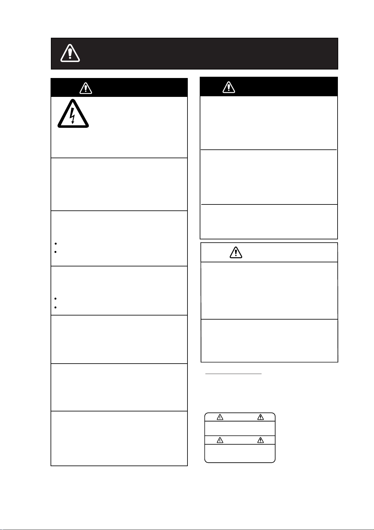
WARNING
Do not open the equipment
unless you are well familiar
with electrical circuits.
ELECTRICAL
SHOCK
HAZARD
Do not set the course changing speed
too high.
The boat will be turned too sharply at the
course change, which could create a very
dangerous situation.
Do not use the autopilot in the
following situation:
Harbor entrance or narrow channel
Where vessels change course often,
such as a cape or small island
Observe the following cautions when
using the autopilot:
Only qualified personnel
should work inside the
equipment.
WARNING
Do not use the ORBIT mode in rough
sea.
Because the boat turns a 360-degree circle
around the waypoint a large wave or strong
wind can cause the boat to capsize.
For the figure eight mode, confirm that
no objection is in the general vicinity
of the waypoint.
The distance from the waypoint to the
turning point depends on boat's speed.
Set the turn rate properly.
Setting the too high rate may cause sudden
turn.
CAUTION
In case of power failure turn off the
autopilot or manually steer the vessel.
Maintain a vigilant watch
Watch for drifting of vessel
In an emergency, manually steer the
vessel.
The autopilot cannot avoid vessels, etc.
automatically.
Do not use the SIMULATION mode on
the boat.
The rudder may move. This is specialpurpose mode for technicians.
When connecting a geomagnetism
detection type heading sensor, correct
magnetic field deviation.
If an autopilot is used without the compensation, unexpected course change may occur.
Leaving the equipment in the AUTO or
NAV mode during power failure will cause
wear on the rudder mechanism.
Use the correct fuse.
Use of a wrong fuse can cause fire or
damage the equipment.
WARNING LABEL
A warning label is attached to the
processor unit. Do not remove the
label. If the label is missing or damaged,
contact your dealer about replacement.
To avoid electrical shock, do not
remove cover. No user-serviceable
parts inside.
WARNING
Name: Warning Label (1)
Type: 86-003-1011
Code No.: 100-236-231
i
Page 4

TABLE OF CONTENTS
FOREWORD ........................................................................................................ iv
SYSTEM CONFIGURATION................................................................................. v
1. PRINCIPLE OF THE AUTOPILOT................................................................1-1
Principle of Autopilot..........................................................................................................1-1
Principle of Operation........................................................................................................ 1-2
2. BASIC OPERATION......................................................................................2-1
2.1 Operating Controls.................................................................................................... 2-1
2.2 Turning On/Off........................................................................................................... 2-2
2.3 Adjusting Brilliance and Contrast ............................................................................... 2-3
2.4 Displays....................................................................................................................2-4
2.4.1 Choosing the display mode .............................................................................. 2-4
2.4.2 Selecting the data shown on Dat a Display........................................................ 2-5
3. STEERING MODES ...................................................................................... 3-1
3.1 STBY Mode............................................................................................................... 3-1
3.2 AUTO Mode.............................................................................................................. 3-2
3.2.1 Using the AUTO mode...................................................................................... 3-2
3.2.2 ADVANCED AUTO mode.................................................................................. 3-3
3.3 NAV Mode.................................................................................................................3-4
3.3.1 S t ar ting the NAV mode ..................................................................................... 3-4
3.3.2 Selecting sailing method of NAV mode............................................................. 3-5
3.3.3 Switching waypoint........................................................................................... 3-6
3.3.4 Selecting the boat’s steeri ng behavior after arriving
at your destination waypoint...................................................................................... 3-7
3.4 TURN Mode.............................................................................................................. 3-8
3.5 REMOTE Mode.......................................................................................................3-16
3.6 DODGE Mode......................................................................................................... 3-20
3.6.1 Dodging in STBY mode.................................................................................. 3-20
3.6.2 Dodging in AUTO or NAV mode...................................................................... 3-21
4. MENU OPERATION ......................................................................................4-1
4.1 STBY Mode Menu..................................................................................................... 4-1
4.1.1 Settin g p arameters........................................................................................... 4-2
4.1.2 Settin g oth er menu item.................................................................................. 4-10
ii
Page 5

5. ALARMS........................................................................................................ 5-1
5.1 ALARM SETUP Menu................................................................................................5-1
5.1.1 Selecting the alarm buzzer................................................................................5-2
5.1.2 Selecting the beep pattern................................................................................5-2
5.1.3 Setting the watch alarm ....................................................................................5-3
5.1.4 Setting the heading deviation alarm..................................................................5-3
5.1.5 Setting the cross-track error limit.......................................................................5-4
5.1.6 Setting the speed alarm....................................................................................5-5
5.1.7 Setting the depth alarm.....................................................................................5-6
5.1.8 Setting the temperature alarm...........................................................................5-7
5.1.9 Setting the trip distance alarm...........................................................................5-7
5.1.10 Clearing the trip distance ................................................................................5-8
5.2 Alarm Information......................................................................................................5-9
6. MAINTENANCE & TROUBLESHOOTING...................................................6-1
6.1 Preventive Maintenance............................................................................................6-1
6.2 Replacement of Fuse.................................................................................................6-2
6.3 Diagnostics................................................................................................................6-2
6.4 Clearing Memories.....................................................................................................6-6
6.5 Error Messages.........................................................................................................6-7
MENU TREE................................................................................................... MN-1
SPECIFICATIONS...........................................................................................SP-1
INDEX............................................................................................................... IN-1
iii
Page 6

FOREWORD
A Word to the Owner of the NAVpilot-511/520/611
Congratulations on your choice of the F URUNO NAVpilot - 511/520/611 AUTOPILOT.
For 60 years FURUNO Electric Company has enjoyed an enviable repu tation for innovative
and dependable marine electronics equipment. This dedication to excellence is furthered by
our extensive global network of agents and dealers.
Your autopilot is designed and constructed t o meet the rigorous demands of the marine
environment. However, no machine can perform its intended function unless installed,
operated and maintained properly. Please carefully read and follow the recommended
procedures for operation and maintenance.
We would appreciate hearing from you, the end-user, about whether we are achieving our
purposes.
Thank you for considering and purchasing FURUNO equipment.
Features
• Self-learning program to continuously improve the st eering parameters for safe and
expeditious navigation
• Two steering modes – AUTO (Heading Control System) and NAV (Track Control System)
• Dodging from the control unit or remote controller
• Available for solenoid drive and reversible hydraulic
• Max. six control units may be connected (using two ports of the processor unit)
• Menu operation for simplified control
• Display modes: Autopilot/Track control modes with rudder angle, L/L, Highway, Two
customized displays, compass rose
iv
Page 7
SYSTEM CONFIGURATION
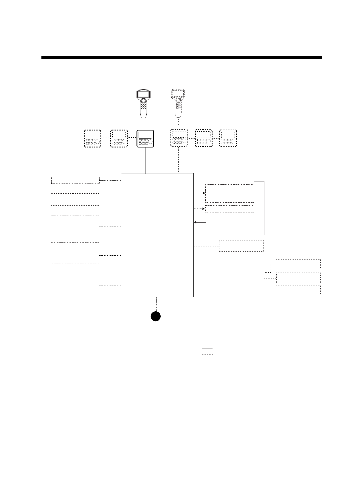
PC
Heading sensor
PG-500
External buzzer
Navigator
(NMEA0183)
FAP-5001/5011/6011 (Max. 6)* or FAP-5021 (Max. 2)
Control Unit
Processor Unit
FAP-5002
Reversible pump or
Electromagnetic valve unit
Clutch
Rudder Reference Unit
FAP-6111
Remote Controller
Ship's steering system
Remote Controller
RD-30 (Max. 3)
(NMEA0183)
12-24 VDC
*: Any combination of FAP-5001, 5011 and 6011 is available.
Also, FAP-5021 can be connected at the end of series.
System configuration of NAVpilot-511/520/611
Distributor FAP-6800
Remote controler
Dial type: FAP-5551, FAP-5552
Button type: FAP6211, FAP-6212
Lever type: FAP-6221, 6222
Dodge type: FAP-6231, 6232
: Standard
: Option
: User supply
Remote Controller
Remote Controller
v
Page 8

This page is intentionally left blank.
vi
Page 9

1. PRINCIPLE OF THE AUTOPILOT
Principle of Autopilot
An autopilot is an automatic device for steering a vessel and maintaining its
heading in an intended direction. Boat and ship operators can really appreciate
the advantages of the autopilot – It steers t he boat f or you so that you are free to
carry out navigational checks, trim adjustments, etc. or to simply relax and enjoy
the ride.
The NAVpilot-511/520/611 autopilot utilizes a pr oportional rate system to steer
the boat. This system is similar to the highly accurate and reliable s ystems used
on aircraft, missiles and space vehicles. The proportional rate autopilot provides
the necessary course correction to the steering system relat ive to the speed and
amount that the boat moves off course.
Dead band is the area (in degrees) that an auto pilot is allowed to drift before
correcting the vessel’s course. Since your NAVpilot-511/520/611’s advanced
processor does not utilize a dead-band, it will not drift or wander, and will steer
the boat reliably and accurately, taking action if even a minute course error
occurs.
Because wandering is eliminated, the proportional rate autopilot uses less power
and lowers wear and tear on the steering system. Course correct ion is smooth,
and consistent, and the boat will not j erk back and forth at any speed.
1-1
Page 10

1. PRINCIPLE OF THE AUTOPILOT
Principle of Operation
In the AUTO modes, the heading information from a heading sensor is
continuously compared with the course that is set on the aut opilot’s controller. (In
the NAV mode, the course to t he waypoint is received from a plotter connected
to the NAVpilot-511/520/611). With the boat on course, these two signals are
equal.
If the boat drifts off course, the difference between the primary heading and the
set course will change proportionall y and there will be an imbalance at a
comparator. The comparator’s output will then move up or down depending on
whether the course error is to the left or right of the set course.
The rudder will continue to turn the vessel until a balanced condition is obtained
at the comparator, at which point the drive to the rudder stops.
The rudder position is determined by a rudd er reference unit and continuously
monitored by the processor unit.
1-2
Page 11
2. BASIC OPERATION
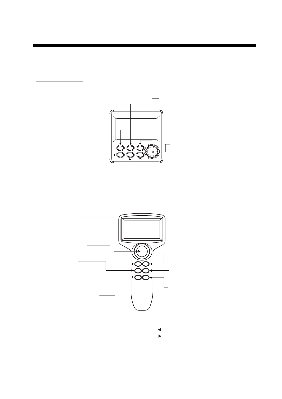
2.1 Operating Controls
NAVpilot-511/611
TURN/MENU key
Press once: Opens the TURN menu.
Press twice: Opens the mode menus.
PORT key*
Steers the boat to port.
STBY/POWER key
Long press: Turns power off.
Momentary press: Turns power on;
Selects the STBY
(manual) mode.
AUTO key
Selects the AUTO mode.
STARBOARD (STBD) key*
Steers the boat to starboard.
Course control knob**
Rotate: Selects menu items and options;
Press: Confirms the menu setting.
NAV key
Selects the NAV mode.
Sets the course on Auto mode.
NAVpilot-520
Course control knob**
Rotate: Selects menu items and options;
Sets the course on Auto mode.
Press: Confirms the menu setting.
PORT key*
Steers the boat to port.
STBY/POWER key
Long press: Turns power off.
Momentary press: Turns power on;
Selects the STBY
(manual) mode.
TURN/MENU key
Press once: Opens the TURN menu.
Press twice: Opens the mode menus.
STARBOARD (STBD) key*
Steers the boat to starboard.
AUTO key
Selects the AUTO mode.
NAV key
Selects the NAV mode.
*This knob is called as "ENTER KNOB" in the menu indication.
**Described as below in the text.
[ ]: [PORT] key
[ ]: [STBD] key
Control unit, front view
2-1
Page 12
2. BASIC OPERATION
2.2 Turning On/Off
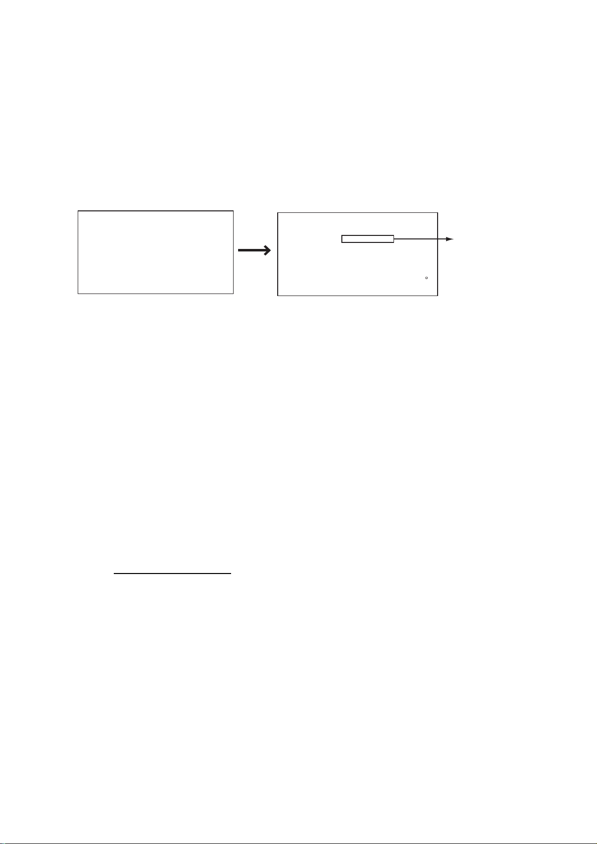
Press the [STBY/POWER] key to turn the unit on. (For PG-500, see Note 2
shown below.) A beep sounds and the equipment proceeds in the sequence
shown below, showing product information and startup test results. The startup
test checks the ROM, RAM, backed up data and communication between the
control unit and processor unit, and also checks for the presence of heading
from the sensor and rudder angle information from the rudder angle ind icator. If
NG appears, an appropriate message will also appear on the screen. If NG is
shown, contact your dealer for advice.
AUTO PILOT
NAVPILOT-511*
(520)
FURUNO ELECTRIC CO., LTD
*For Navpilot-611, "NAVPILOT" appears.
START UP TEST
PROCESSOR OK 6454002-**.**
CONTROLLER OK 6454003-**.**
PROCESSOR UNIT OK OK OK
CONTROLLER OK OK OK
HEADING SENSOR OK 359.9
RRU OK P12.3
CONTROLLER ID 1
ROM RAM BACKUP
-------------------------------------------
**.** : Program version no.
Navpilot-520: 645004-**.**
Navpilot-611: 645005-**.**
Startup sequence
After the startup test is completed, “STBY” appears on the screen. This means
that the equipment may now be operated manually.
Note 1: The first time you turn on the power, you are asked to select Normal,
Installation or Simulation mode. Rotat e the course cont rol knob to select
the appropriate mode, and then press it.
Note 2: When the Integrated Heading Sensor PG-500 is connected, turn on the
NAVpilot-511/520/611 and wait four minutes before leaving port in order
to allow time for the PG-500 heading data to stabilize.
Note 3: The example screens shown in this manual may not match the screens
you see on your display. The screen you see depends on your system
configuration and equipm ent settings.
Turning the power off
Press and hold down the [STBY/POWER] key until the screen goes blank.
2-2
Page 13
2.3 Adjusting Brilliance and Contrast
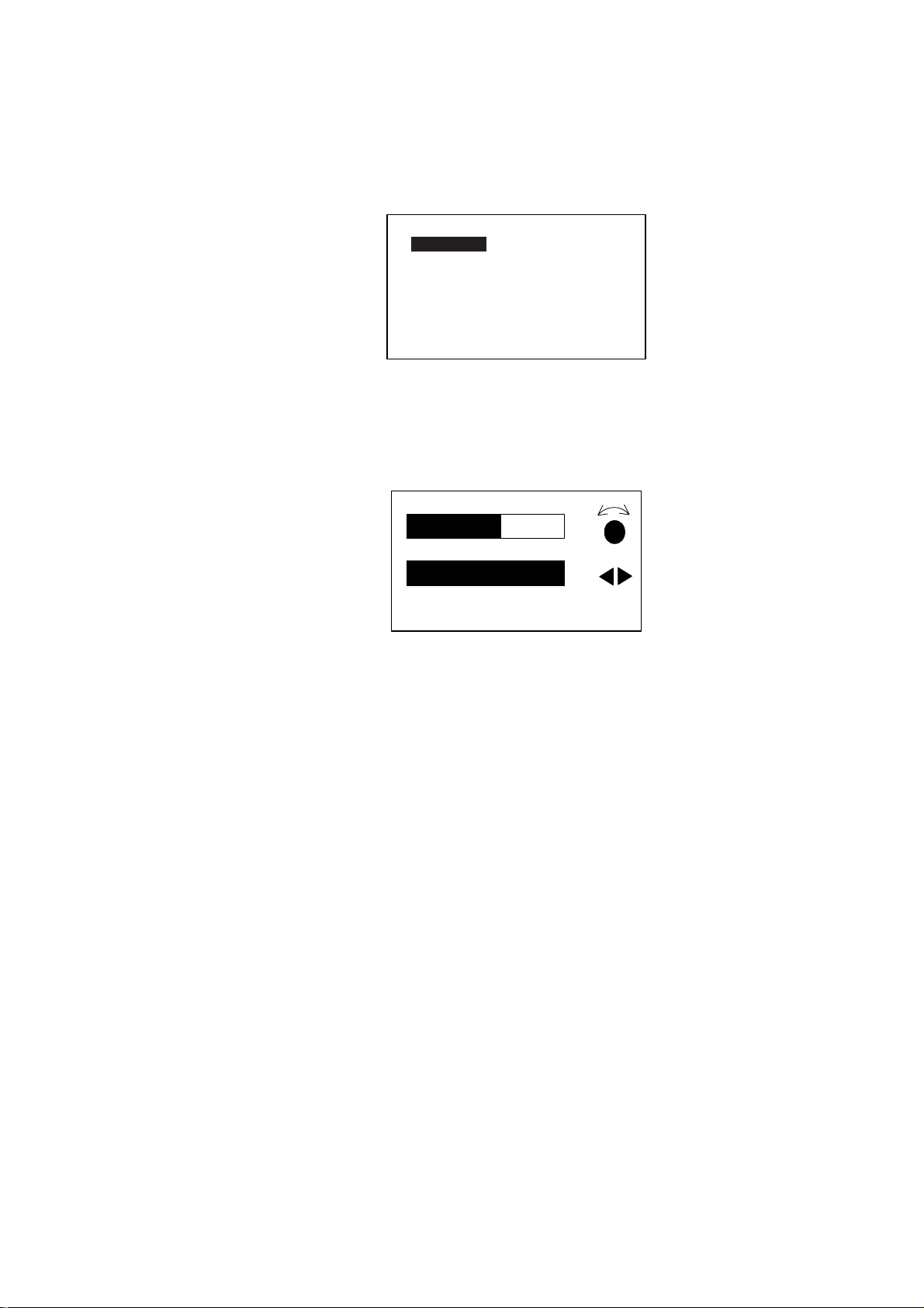
The brilliance and contrast can be adjusted as below:
1. Press the [TURN/MENU] key twice to show the main menu.
MESSAGE
CONTRAST/BRILLIANCE
ALARM SETUP
PARAMETER SETUP
SYSTEM SETUP
TEST: OFF
SYSTEM DATA
Main menu (ex. STBY mode)
2. Rotate the course control knob to choose “CONTRAST/BRILLIANCE”, and
then press it.
The CONTRAST/BRILIANCE window appears.
2. BASIC OPERATION
CONTRAST
10
BRILLIANCE
8
PUSH MENU KEY TO RETURN
TO PREVIOUS MENU
Contrast, brilliance window
3. Rotate the course control knob to adjust display contrast; clockwise to raise
the contrast and counter-clockwise to lower it. (16 levels are available.)
4. Press the [PORT] or [STBD] key to adjust display brilliance, [PORT] to lower
the brilliance and [STBD] to raise it. (Eight levels are available.)
To close the CONTRAST and BRILL window , press the [TURN/MENU] key
twice.
2-3
Page 14
2. BASIC OPERATION
2.4 Displays
2.4.1 Choosing the display mode
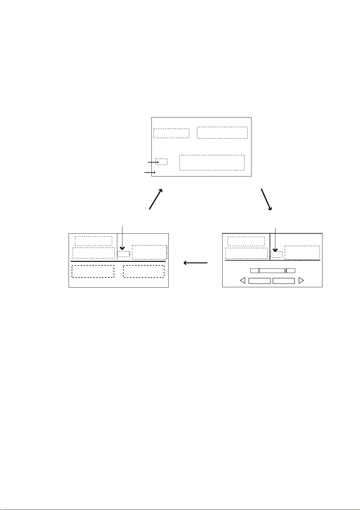
There are three types of displays: Norm al display 1, Normal display 2, and Data
display.
To choose a display mode, press a mode key (AUTO, NAV, STBY). Each time a
mode key is pressed the display changes in the sequence shown below.
[3]
(Mode)
(Course)
(Data 1)*
(Mode)
HDG
Heading mode
Page No.
[1]
Heading mode
HDG
(Heading)
(Data 2)*
*: One or two data can be selected
to be shown at the installing.
For detail, see the Installation manual.
(Data display)
(Course)
(Heading)
(Normal display 1)
[2]
Heading mode
(Mode)
(Course)
(Data)
P
(Normal display 2)
HDG
(Heading)
S
2-4
Displays
Page 15
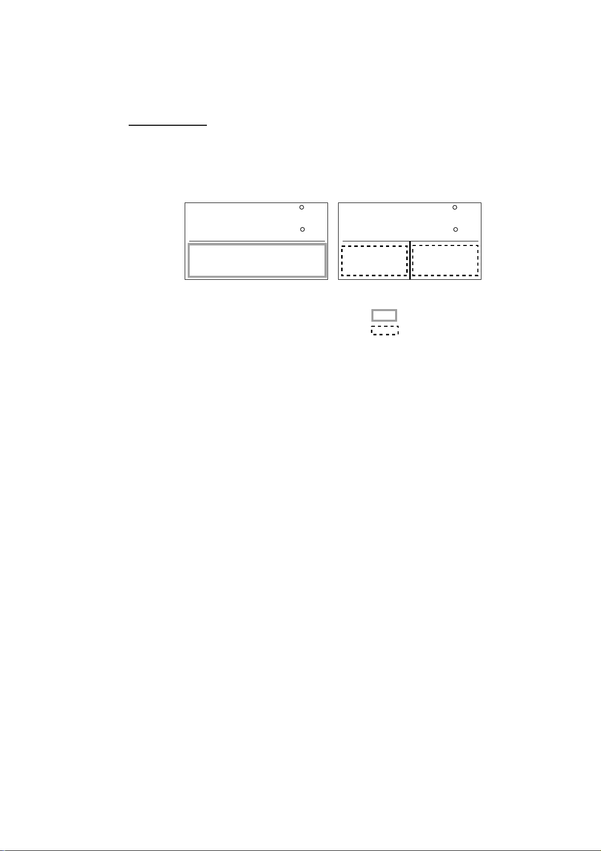
2.4.2 Selecting the data shown on Data Display
Data Display may be set up to suit your operating needs as be low.
Selecting dat a
In the STBY mode, you can select which data you want to display in the columns
shown in the figure below. For Normal Display 2, you may choose which data
you want to show on the analog indicator.
2. BASIC OPERATION
STBY
HDG
Normal Display 2
1. Press the [STBY] key to show the STBY mode.
2. Press the [STBY] key several times to show the one of screens shown above,
which you want to change the data.
3. Press the course control knob.
4. For two data display, press the [PORT] or [STBD] key to select the column
desired.
5. Rotate the course control knob to select the data you want t o show.
Available data and analog indicators are listed on the next page.
6. Press the course control knob to finish.
20.5
145.9
STBY
HDG
20.5
145.9
Data Display
Analog indicator column
Data column
2-5
Page 16
2. BASIC OPERATION
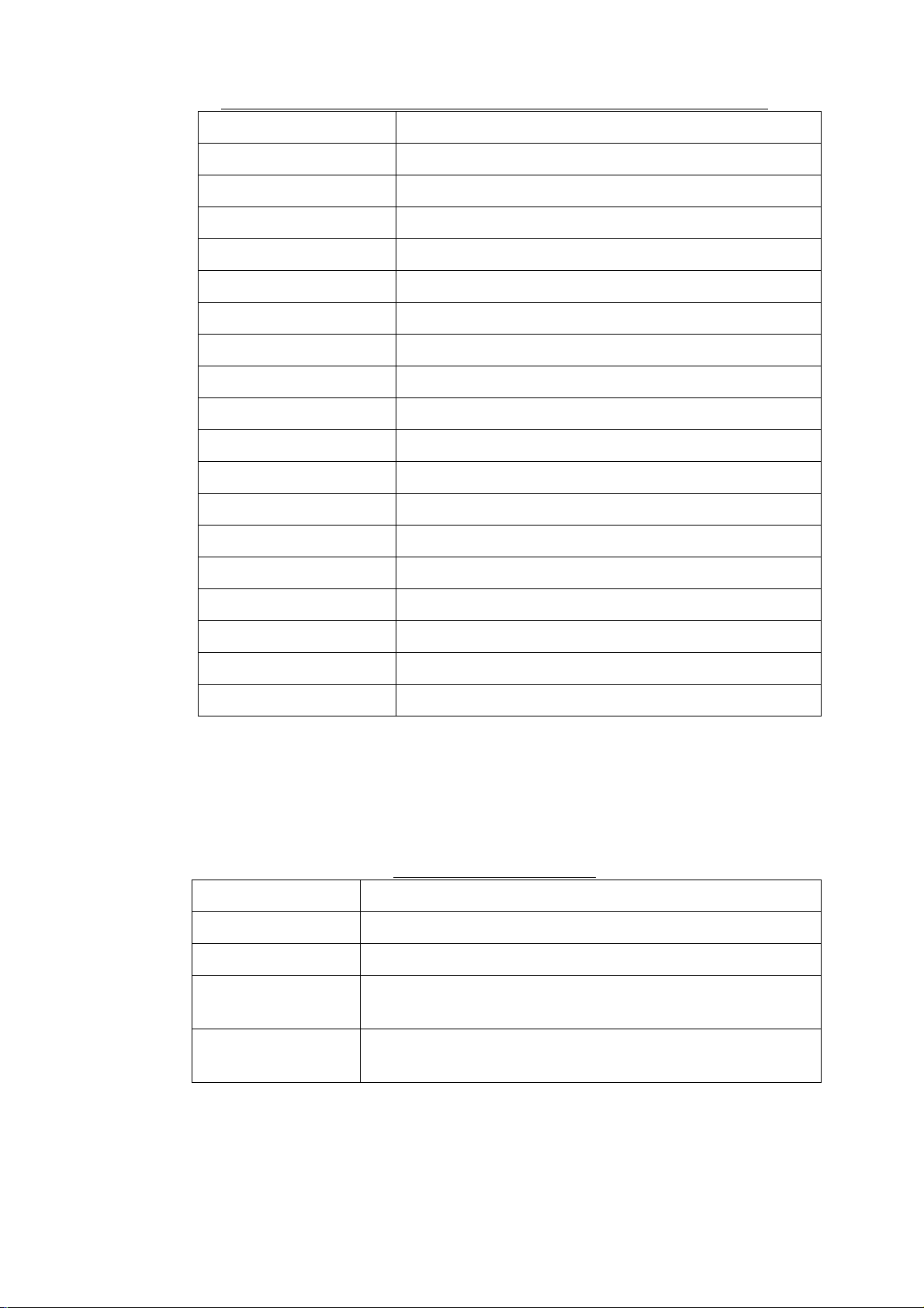
Data available for Normal display 2, Data display and Graphic display
Item Displayed data
POS Own ship’s position (L/L)
COG Course over ground
SOG Speed over ground
STW Speed through water
TEMP Water temperature
DPT Depth
BRG Bearing to waypoint
RNG Range to waypoint
WPT Waypoint position (L/L)
XTE Cross-track error
TTG Time-to-Go to Destination
ETA Estimated Time of Arrival
DATE Date
TIME Time
WIND TRUE* Wind direction and speed (True)
WIND RELATIV** Wind direction and speed (Relative)
VOLT Input/output power voltage to the processor unit
TRIP Trip distance
*True: The Speed and direction (relative to due north)
**Relative: The direction (in relation to ship’s bow) and speed of the wind as it
appears to those on board, relative to the spee d and direction of
the boat; combination of the true wind and the wind caused by the
boat’s movement.
Analog indicator selection
Item Displayed data
RUDDER ANGLE Rudder angle
2-6
DEVIATION Deviation of heading
RUDDER/XTE Rudder angle will appear while in the STBY and AUTO
modes, XTE will appear while in the NAV mode.
DEV./XTE Deviation will appear in the STBY mode and AUTO modes,
XTE will be shown while in the NAV mode.
Page 17
3. STEERING MODES
The NAVpilot-511/520/611 system is capable of six primary steering modes:
STBY (manual), AUTO, NAV, TURN, REMOTE (FU and NFU) and DODG E.
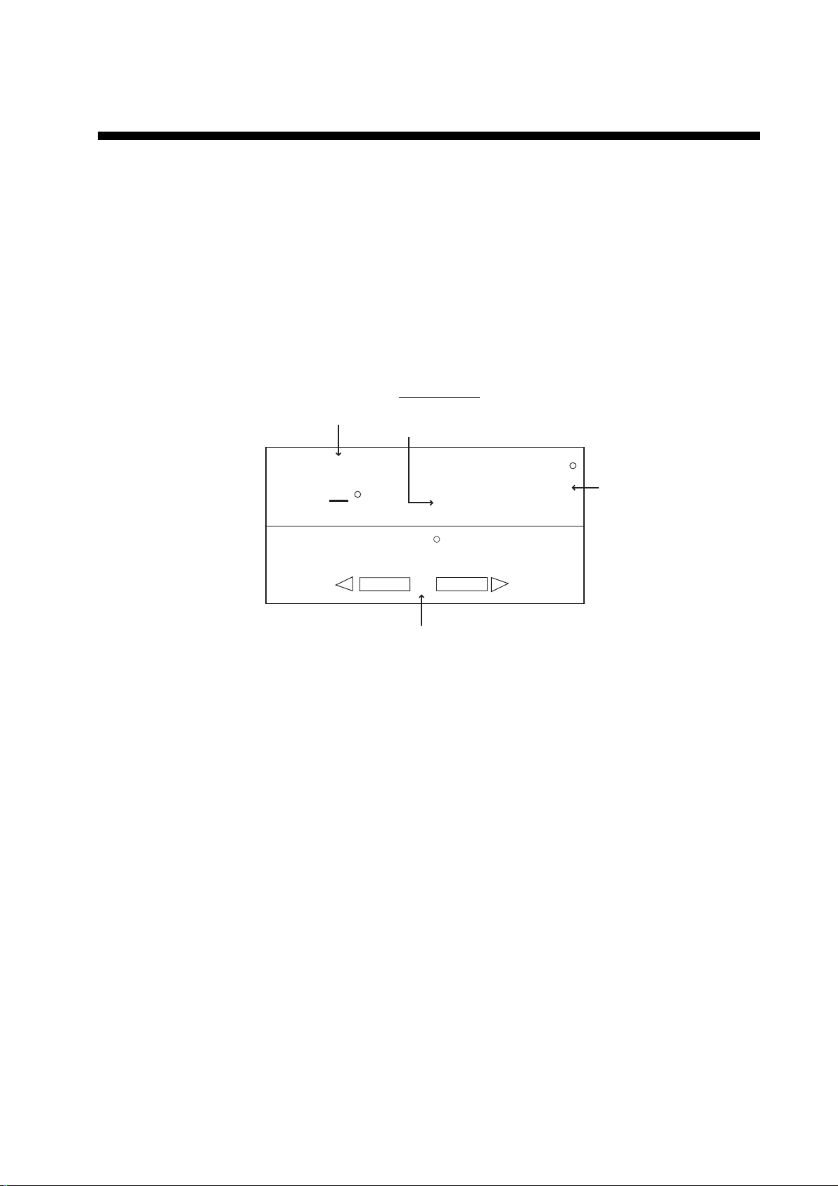
3.1 STBY Mode
After turning on the power, the equipment goes to the STBY mode.
This is a manual steering mode. When sailing into or out of a harbor, steer the
vessel in the STBY mode by using the ship’s steering wheel (helm).
Press the [STBY] key.
STBY mode
(manual steering mode)
Heading mode
M: Magnetic
T: True
STBY
RUDDER ANGLE
20
40
10 5
Rudder angle (XTE or Deviation)
STBY mode display (Ex. Normal Display 2)
0
HDG
359.9
M
40
5 10
20
Heading from
heading sensor
3-1
Page 18
3. STEERING MODES
3.2 AUTO Mode
3.2.1 Using the AUTO mode
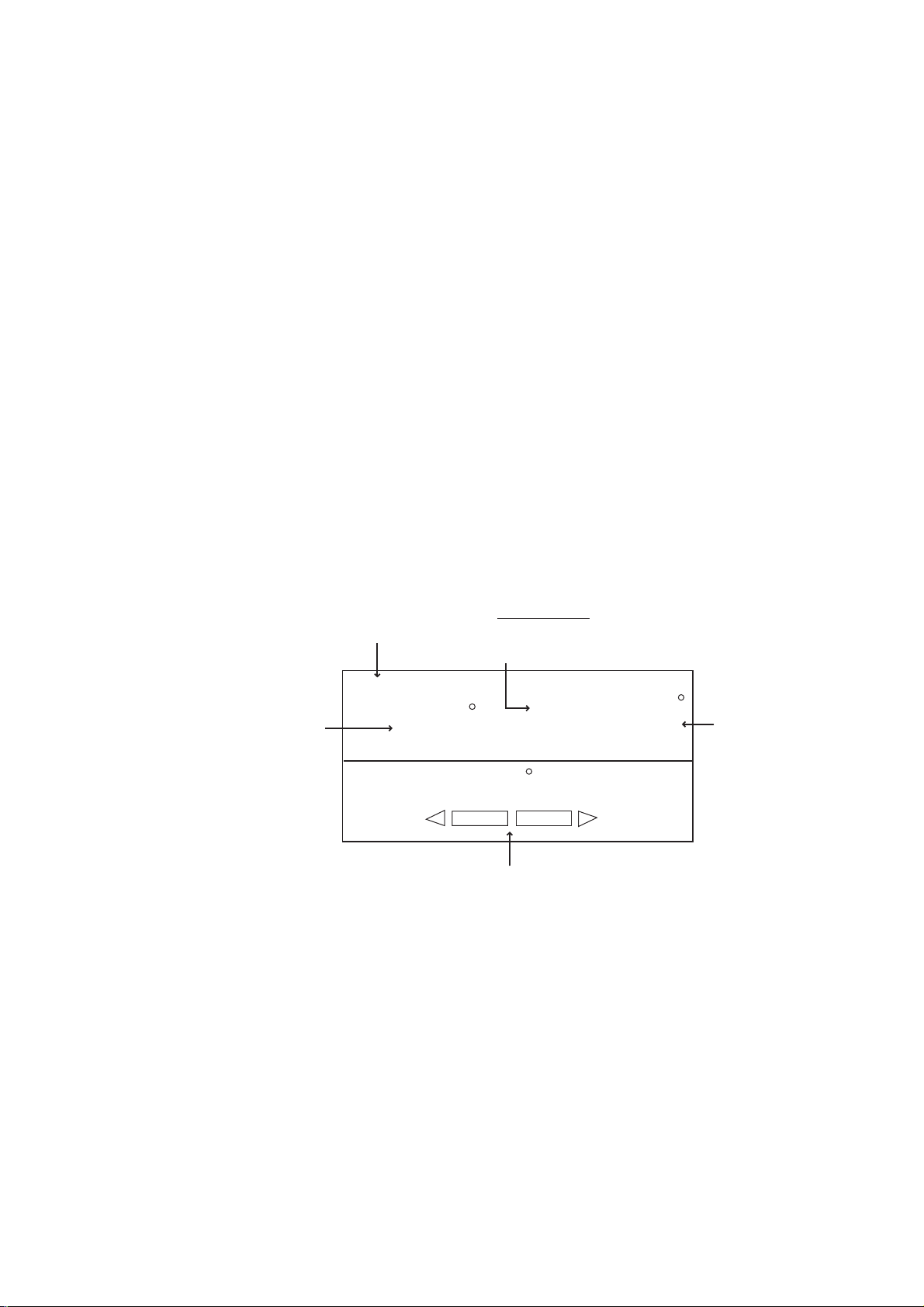
The NAVpilot-511/520/611’s AUTO mode steers the boat automatically on a
course set by the operator.
Note: The AUTO mode will not compensate for the effects of wind or tide, which
can push you off course in the athwart ship direction. Use t he AUTO mode
for short, straight voyages. Otherwise switch to the NAV mode which is
described on page 3-4.
1. Direct the boat to the intended course desired.
2. Press the [AUTO] key to activate the Auto mode.
Your boat will automatically maintain the current course at the moment the
[AUTO] key is pressed.
Whenever the heading deviates from the set course, the NAVpilot-511/520/611
automatically adjusts the rudder to return the boat to the set course.
3. To change or readjust the course setting in the AUTO mode, simply rotate the
course control knob to the desired course.
4. Press the [STBY] key to leave AUTO steering in an emergency. You can
steer your boat by the helm.
Heading control mode
Course selected by
the course control knob
AUTO mode display (Ex. Normal Display 2)
(AUTO mode)
AUTO
359
RUDDER
Rudder angle (XTE or Deviation)
Heading mode
M: Magnetic
T: True
HDG
M
359.9
Heading from
heading sensor
0
20
40
10
10
20
40
3-2
Page 19
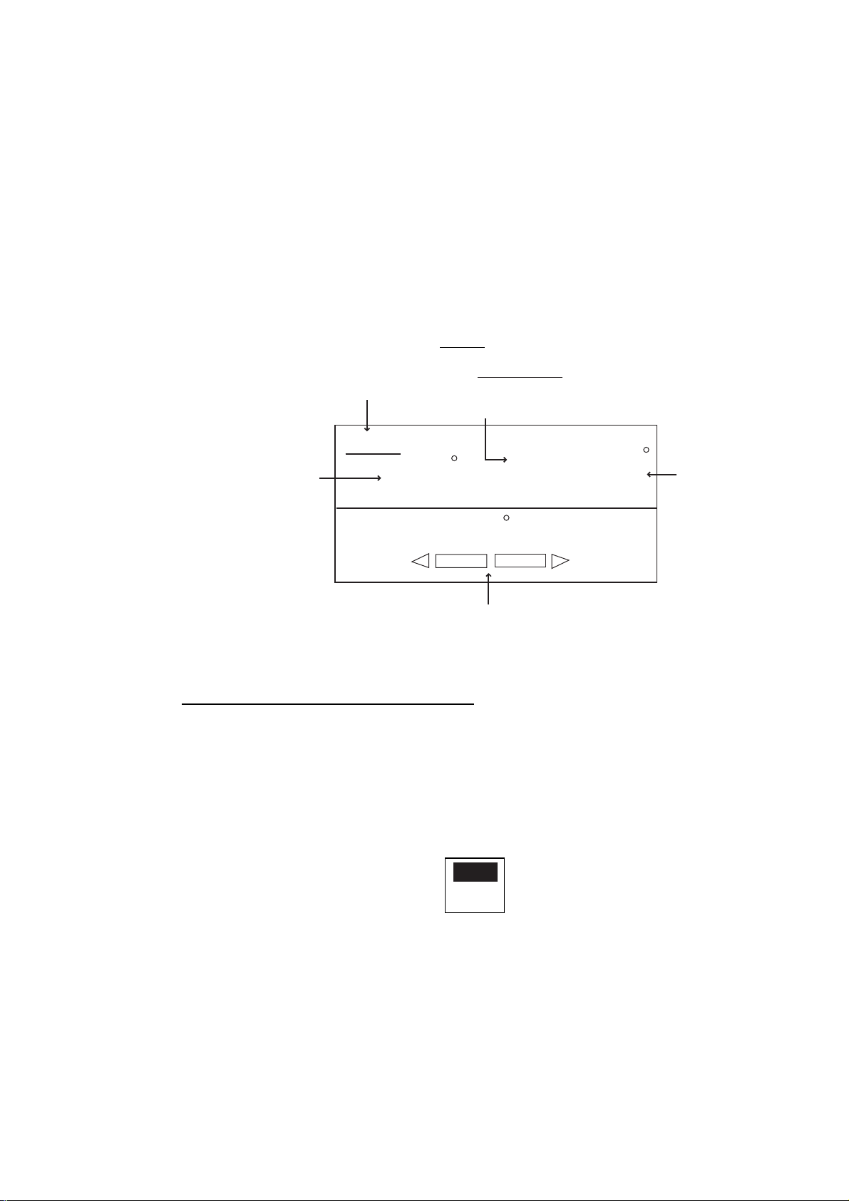
3.2.2 ADVANCED AUTO mode
AUTO mode will maintain a set course, but your vessel’s course may be shifted
by the effects of current or wind. ADVA NCED AUTO mode maintains a set
course while compensating for the effects of wind and tide. Note that your
NAVpilot-511/520/611 must be connected to a (GPS) which outputs own ship’s
position data (L/L) in NMEA0183 format to t he NAVpilot-511/520/611.
In the ADVANCED AUTO mode, the NAVpilot-511/520/611 will calculate your
course based on your present position and hea ding, and by setting a virtual
“waypoint” in its memory to navigate towards. If either tide or wind begins to
push you off course, the NAVpilot-511/520/611’s processor will correct your
heading accordingly. In this mode, “AUTO
3. STEERING MODE
” appears on the display.
Heading control mode
(Indicated with underline)
Course selected by
the course control knob
AUTO
359
RUDDER
Heading mode
M: Magnetic
T: True
HDG
M
359.9
Heading from
heading sensor
0
20
40
Rudder angle (XTE or Deviation)
ADVANCED AUTO mode display (Ex. Normal Display 2)
Enabling the ADVANCED AUTO mode
You can select whether to use the ADVANCED AUTO mode or not as follows.
1. In the AUTO mode, press the [ TURN/MENU] key twice to show the AUTO
mode menu.
2. Rotate the course control knob to select “ADVANCED AUTO”, and then
press the course control knob to show the advanced auto options window.
10 5
5 10
20
40
OFF
ON
Advanced auto options window
3. Rotate the course control knob to select “ON”.
When you want to finish the ADVANCED AUTO mode, select “OFF”.
4. Press the course control knob to close the menu.
Note: You can switch AUTO and ADVANCED AUTO mode by holding the
[AUTO] key down until the message “ADVANCED AUTO ON (OFF)”
appears.
3-3
Page 20
3. STEERING MODES
3.3 NAV Mode
3.3.1 Starting the NAV mode
If a destination waypoint is set on a GPS / Plotter, the NAVpilot-511/520/611 can
receive this information and guide t he boat to the destination waypoint as
determined by the plotter. To use the NAV mode, complete the following steps.
Note: It takes 15 seconds to activate the NAV mode after the
NAVpilot-511/520/611 receives the above information.
1. Set the destination waypoint (or route) on t he plotter.
2. Manually steer the boat towards the waypoint.
3. Press the [NAV] key.
You are asked which port is used for the NAV mode PORT 1 or PORT 2
( depending on menu setting) . Press the course control knob to go to the NAV
mode..
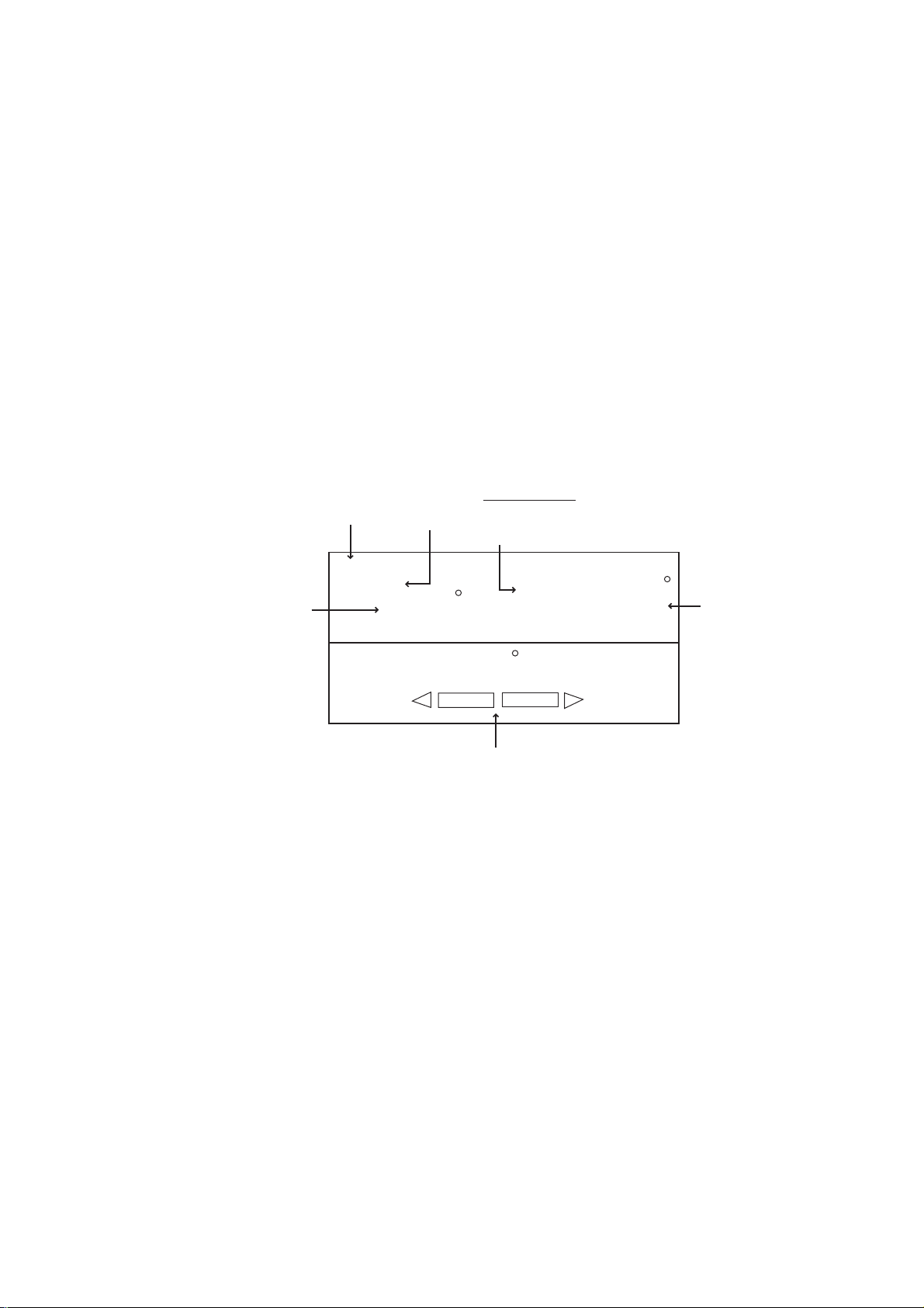
Heading control mode
(Indicated with underline)
Course to the
destination waypoint
Selected
Navigator
NAV
SRC: PORT1
359
RUDDER
Heading mode
M: Magnetic
T: True
HDG
M
359.9
Heading from
heading sensor
0
10 5
5
10
20
40
40
20
Rudder angle (XTE or Deviation)
NAV mode display (Ex. Normal Displ ay 2)
Note that while in the NAV mode, the course reading on the
NAVpilot-511/520/611 will not always be the same as the waypoint direction
shown on the plotter.
When you want to navigate a route, make sure that your plotter is navigating
towards the nearest or desired waypoint before putting the NAVpilot-511/520/611
into the NAV mode.
4. Press the [STBY] key to terminate the NAV mode.
Note: You can switch the source port between PORT 1 and PORT 2 by pressing
the [NAV] key more than three seconds.
3-4
Page 21
3.3.2 Selecting sailing method of NAV mode
Your vessel may go off course when navigating between wayp oints in the Nav
mode. This can happen when, for example, a command is received from a
remote controller. To get you back on course, two methods are available,
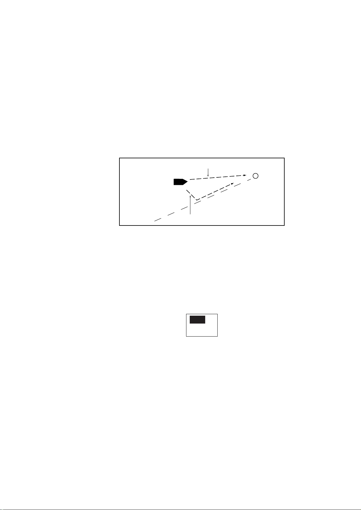
COURSE and XTE. (See figure in below.) If COURSE is selected, the
NAVpilot-511/520/611 will calculate a new course based on your new position
after dodging, etc. that will take you directly to your dest ination waypoint. If XTE
is selected, the NAVpilot-511/520/611 will use XTE or cross track error to steer
the boat towards your ORIGINAL course before dodging. You may select, either
COURSE or XTE as shown below.
COURSE line
3. STEERING MODE
Waypoint
Original course
XTE line
NAV mode, COURSE and XTE
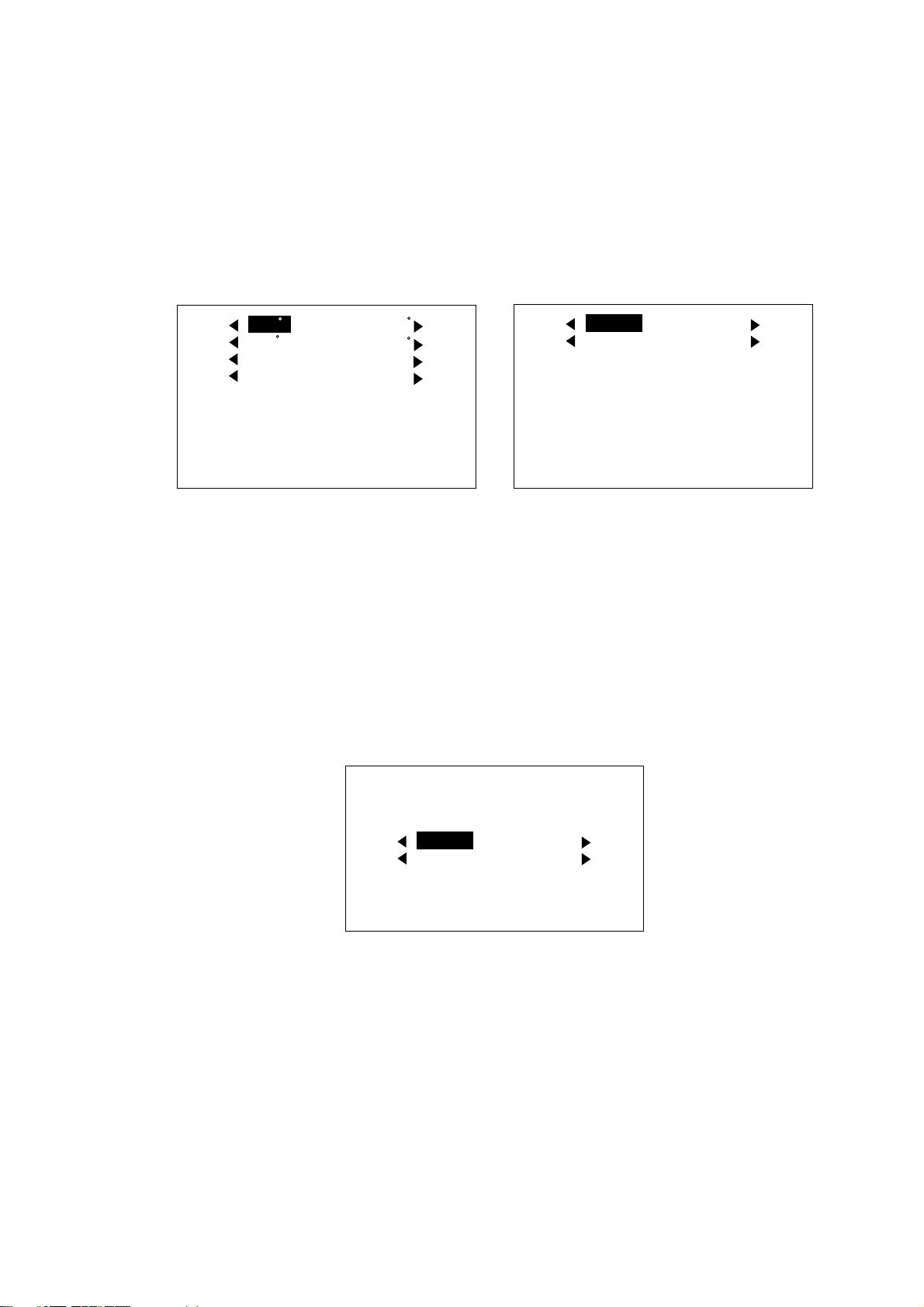
The NAV mode steering method can be selected f r om the menu.
1. In the NAV mode, press the [TURN/ MENU] key twice to show the NAV mode
menu.
2. Rotate the course control knob to select “NAV MODE” on the second page,
and then press it to show the nav mode options window.
XTE
COURSE
Nav mode options window
3. Rotate the course control knob to select XTE or COURSE as appropriate.
5. Press the course control knob, and then press the [TURN/MENU] keys t o
close the menu.
3-5
Page 22

3. STEERING MODES
3.3.3 Switching waypoint
When you arrive at a waypoint on a route while in t he NAV mode, you can switch
to the next waypoint automatically or manuall y. The AUTO setting will
automatically switch to the next destination waypoint when your boat is within
the arrival alarm area (set on the plotter). The MANUAL setting requires operator
confirmation (pressing the course control knob) before switching to the next
waypoint. When in MANUAL switching mode, the NAVpilot-511/520/611 will
sound for five seconds an alarm when the vessel arrives at the dest ination
waypoint.
AUTO: When your boat is within the arrival alarm area, the buzzer sounds
for five seconds and the message “WPT WAS CHANGED”
appears.
MANUAL: The message “WPT WAS CHANGED. PRESS ANY KEY.” appears
when the vessel arrives at the destination waypoint.
1. In the NAV mode, press the [TURN/ MENU] key twice to show the NAV mode
menu.
2. Rotate the course control knob to select “WAYPOINT SWITCHING” on the
second page.
3. Press the course control knob to show the waypoint switching windo w.
AUTO
MANUAL
Waypoint switching options window
4. Rotate the course control knob to select AUTO or MANUAL as appropriate.
5. Press the course control knob and [TURN/MENU] key in order to close the
menu.
3-6
Page 23

3. STEERING MODE
3.3.4 Selecting the boat’s steering behavior after arriving at your
destination waypoint
The “Fishing mode” can be enabled and set up control your boat’s steering
behavior after it reaches the last waypoint in a route. For example, the ORBIT
setting will steer the vessel in a circular pattern around the final waypoint (fishing
spot). The FIGURE EIGHT setting will continually return to the final waypoint in a
clover leaf pattern.
For details of each movement, see the next section “3.4 TURN Mode”. To enable
the fishing mode and set the steering behavior, complete the following steps:
1. Press the [STBY] key and then, [TURN/MENU] key twice to show the STBY
menu.
2. Rotate the course control knob to select “PARAMETER SETUP”, and then
press it to show the parameter setup menu.
3. Rotate the course control knob to select “FISH MODE” on the second page,
and then press it.
4. Rotate the course control knob to select ORBIT TO STBD (starboard),
ORBIT TO PORT or FIGURE EIGHT.
To disable the fishing mode, select OFF. (The ship continues in the same
direction that was active when the boat arrives at the last waypoint.)
5. Press the course control knob, and then press the [TURN/MENU] key twice
to close the menu.
3-7
Page 24
3. STEERING MODES
3.4 TURN Mode
The [TURN/MENU] key provides the various turning motions depending on the
mode in use. There are five different turn type; 180º or 360º turns (for AUTO
mode only), ORBIT, SPIRAL and FIGURE EIGHT. All turn type are available in
clockwise and counterclockwise direction. To activate the TURN mode:
1. Press the [TURN/MENU] key once to show the TURN menu.
This menu will change based on the mode currently in use.
180
360
ORBIT
SPIRAL
FIGURE EIGHT
RADIUS OF ORBIT: 0.05 nm
PUSH MENU KEY IN ORDER TO
GO TO MENU.
AUTO mode
180
360
ORBIT
SPIRAL
ORBIT
SPIRAL
FIGURE EIGHT
RADIUS OF ORBIT: 0.05 nm
PUSH MENU KEY IN ORDER TO
GO TO MENU.
STBY, NAV mode
ORBIT
SPIRAL
Turn menu
2. Rotate the course control knob to select a mode.
The arrow next to the mode name shows the direction to turn.
3. Press the course control knob to execute.
Press the [TURN/MENU] key twice to close the TURN menu.
Note: When TLL data is input from a radar or echo sounder connected, the
following TURN menu appears. For details, see page 3-15.
REEIVED EXTERNAL TLL.
ORBIT
SPIRAL
RADIUS OF ORBIT: 0.05 nm
CANCEL
NAV
ORBIT
SPIRAL
FIGURE EIGHT
TURN menu (inputting TLL data)
3-8
Page 25
3. STEERING MODE
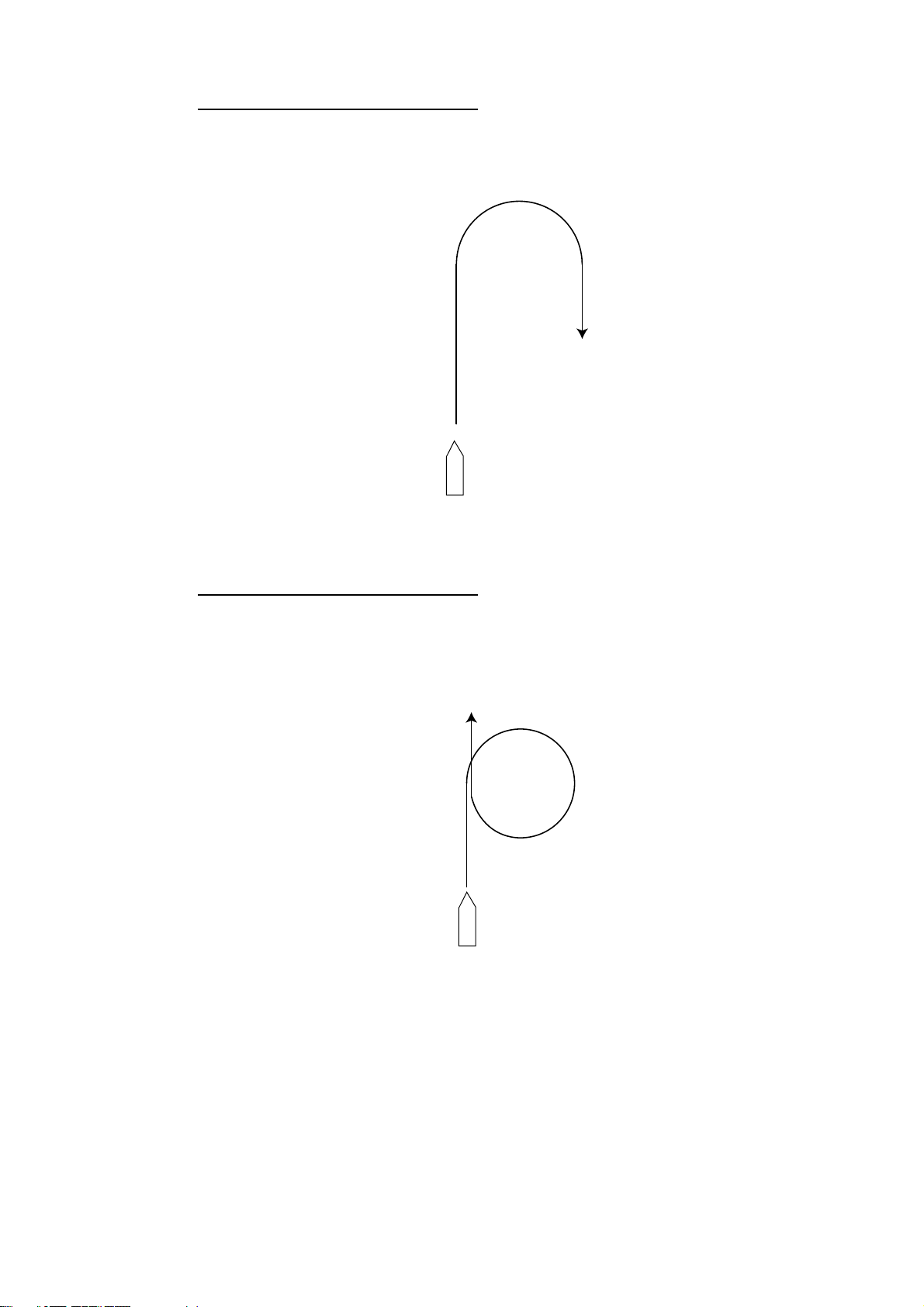
180º TURN (for AUTO mode only)
This function changes the current set course by 180º in the opposite direction.
After the 180º turn completely, the message “TURN COMPLETED” appears.
Return to the AUTO mode by pressing the course control knob.
Example of 180º maneuver in turn mode
360º TURN (for AUTO mode only)
This function also provides a continuous turn feature with a constant rate of turn
in a circle. This may be used for circling fish, purse seining, etc.
After the 360º turn is complete, the message “TURN COMPLETED” appears.
Return to the AUTO mode by pressing the course control knob.
Example of 360º maneuver in turn mode
3-9
Page 26
3. STEERING MODES
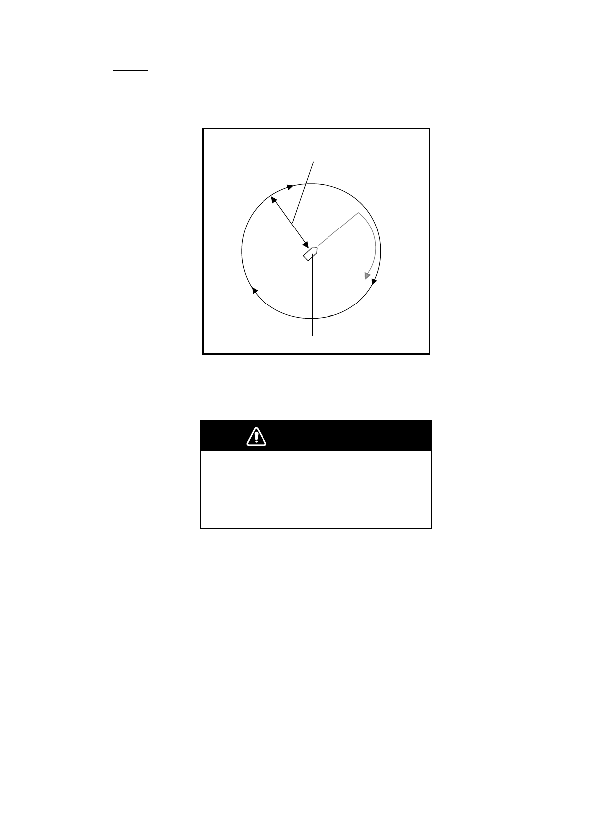
ORBIT
When ORBIT is enabled, your boat will orbit around the boat’s current position.
If ORBIT is enabled while in the NAV mode, the boat orbits around the (last)
waypoint. This function requires a plotter or GPS be connected.
Radius of orbit
(set on menu)
The boat’s position at the ORBIT is selected.
Example of orbit maneuver (ex. clockwise)
To set parameters for ORBIT, operate the autopilot as shown below.
WARNING
Do not use the ORBIT mode in rough sea.
Because the boat turns a 360-degree circle
around the waypoint a large wave or strong
wind can cause the boat to capsize.
1. Press the [TURN/MENU] key once to show the TURN menu.
2. Rotate the course control knob to select “RADIUS OF ORBIT”, and then
press it to circumscribe the value with a double rectangle.
3. Rotate the course control knob to set the radius of orbit (Setting range: 0.05
to 9.99 nm), and then press it.
Note: The radius of orbit may be changed while the orbit mode activates.
3-10
4. Reduce boat’s speed less than 10 kt.
Page 27
3. STEERING MODE
5. Rotate the course control knob to select "◄ORBIT" or "ORBIT►", and then
press it.
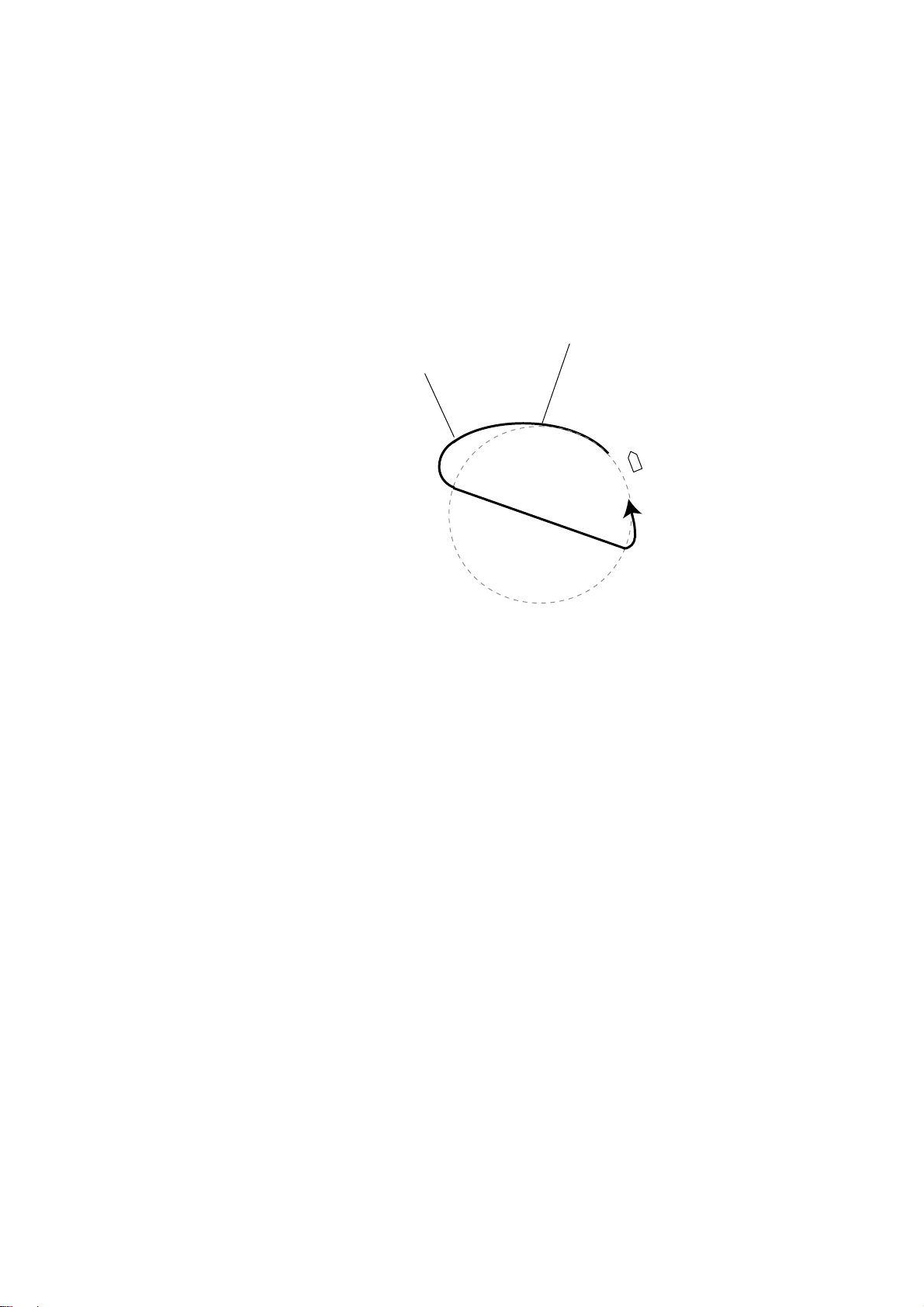
The message “START TO TURN BY FISHING MODE” appears, and the boat
runs for the distance set at step 3, and then starts making an orbit similar to the
figure on the previous page.
If the boat's speed becomes more than 10 kt while orbiting, the message "TOO
FAST TO FISHING MODE. PLEASE SLOW DOWN LESS THAN 10 kt. PUSH
MENU KEY TO CANCEL AND GO TO AUTO MODE." appears. Reduce boat’s
speed less than 10 kt. In this case, the boat runs as shown below.
The boat’s speed becomes
The boat’s speed becomes
less than 10 kt.
more than 10 kt.
To escape from the ORBIT while it is in use, press [STBY] key.
Note: You can set the radius of orbit also at “PARAMETER SETUP” in the main
menu.
3-11
Page 28
3. STEERING MODES
SPIRAL
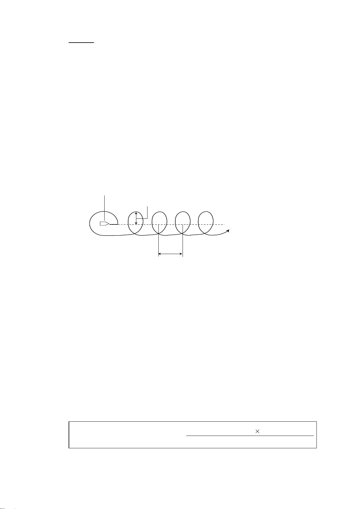
The boat will spiral in the direction of current heading (STBY), set course
(AUTO) or the course to the next waypoint (NAV) that was active at the moment
that the SPIRAL mode is selected. The spiral speed can be set in the menu.
In the NAV mode, the boat steers toward the waypoint (s) spirally. Note that the
NMEA0183 sentence AAM is required from the plotter, and the arrival alarm
range must also be set on the plotter.
Note 1: In the NAV mode, the SPIRAL deactivates the manual waypoint
switching. (See paragraph 3.3.3.)
Note 2: If the boat does not enter the arrival alarm area, it may not be switched
to the next waypoint. Set the arrival alarm range as large as possible
and activate the perpendicular function on the plotter connected.
The boat will continue to orbit until the [AUTO] or [STBY] key is pressed.
SPIRAL starting position
d (radius of orbit)
Orbit of the center of spiral
(Distance between centers of spirals, see next page.)
L
Example of spiral maneuver in turn mode
To execute the spiral, do the following.
1. Press the [TURN/MENU] key twice to show the main menu.
Rotate the course control knob to select “SPIRAL SPEED” on the second page.
For STBY mode;
a) Select “PARAMETER SETUP” in the main menu, and then press the course
control knob to show the PARAMETER SETUP menu.
b) Select “SPIRAL SPEED” in there (on the second page).
2. Press the course control knob.
The current value is circumscribed with a double rectangle.
3. Rotate the course control knob to set the spiral speed. (Setting range: 0.1 to
8.0 kt)
Refer to the formula in below to set the radius of orbit and spiral speed.
3-12
L (distance between centers of spiral: nm) =
6.28 d (radius of orbit: nm)
Vs (ship’s speed : kt)
Vc (spiral speed: kt)
Page 29

3. STEERING MODE
4. Press the course control knob, and then press [TURN/MENU] key once
(twice for STBY mode) to close the menu.
5. Press the [TURN/MENU] key once to show the TURN menu.
6. Rotate the course control knob to select “RADIUS OF ORBIT”, and then
press it to circumscribe the value with a double rectangle.
7. Rotate the course control knob to set the radius of orbit.
(Setting range: 0.05 to 9.99 nm)
8. Press the course control knob.
9. Reduce boat’s speed less than 10 kt.
10. Rotate the [ENTER] knob to select "◄ SPIRAL" or "SPIRAL ►".
11. Press the course control knob to start the spiral function.
The message “START TO TURN BY FISHING MODE” appears, and the boat
runs for the distance set at step 7, and then starts making a spiral similar to the
figure on the previous page.
If the boat's speed becomes more than 10 kt while orbiting, the message "TOO
FAST TO FISHING MODE. PLEASE SLOW DOWN LESS THAN 10 kt. PUSH
MENU KEY TO CANCEL AND GO TO AUTO MODE." appears. Reduce boat’s
speed less than 10 kt. In this case, the boat runs as shown on page 3-11.
12. To escape from the SPIRAL while it is in use, press [STBY] key.
3-13
Page 30
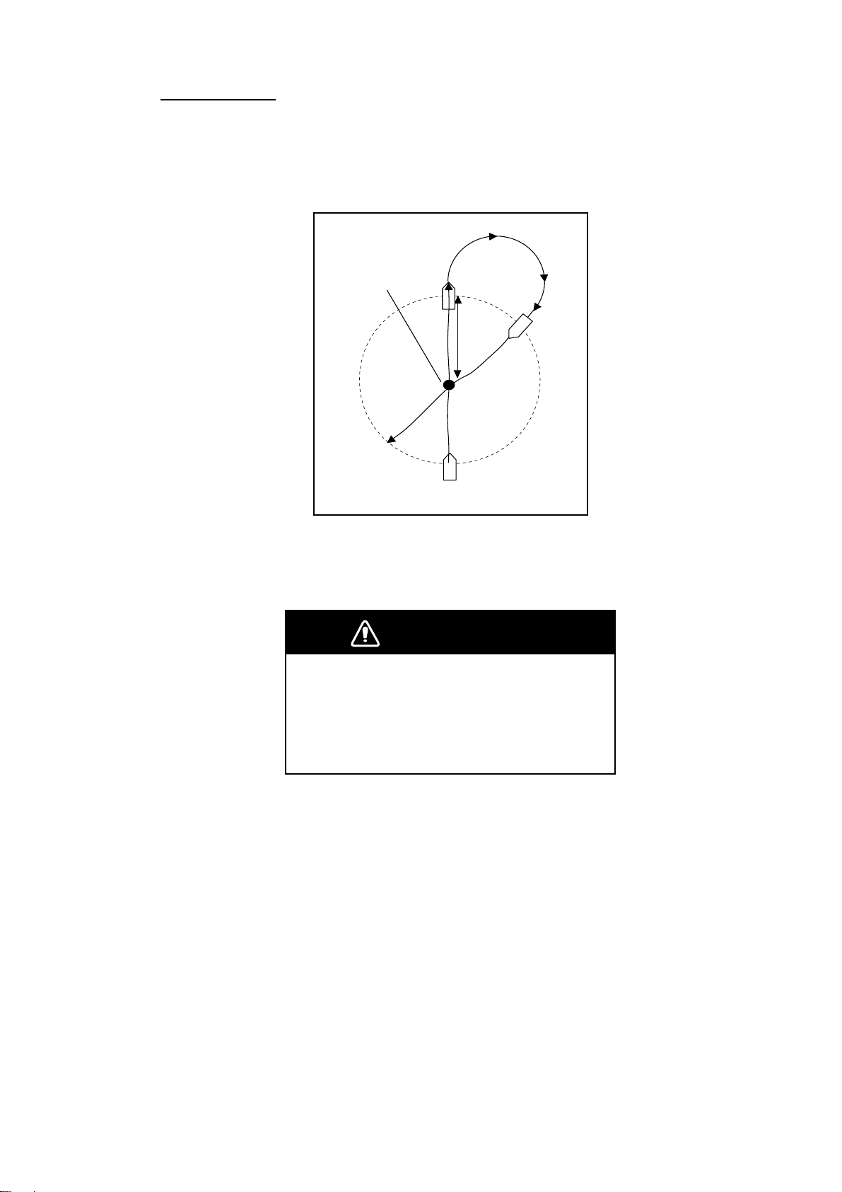
3. STEERING MODES
FIGURE EIGHT
After the boat has traveled the distance "d" set on the TURN menu (or main
menu), it starts turning in a figure eight pattern, automatically returning to the
position where the figure eight mode was initiated. The “d” is set on menu as
RADIUS OF ORBIT.
Boat's position
FIGURE EIGHT
is selected.
d
Example of FIGURE EIGHT (in NAV mode)
Note: Reduce boat’s speed so that the boat can turn smoothly.
WARNING
Confirm that no objection is in the general
vicinity of the waypoint.
The distance from the waypoint to the turning
point may be changed depending on boat's
speed.
1. Press the [TURN/MENU] key once to show the TURN menu.
2. Rotate the course control knob to select “RADIUS OF ORBIT”, and then
press it.
The current value is highlighted.
3. Rotate the course control knob to set the radius for orbit. (Setting range: 0.05
to 9.99 nm.) The radius of orbit may be changed while the figure eight mode
activates.
4. Press the course control knob.
5. Rotate the course control knob to select "FIGURE EIGHT".
9. Press the course control knob to start the figure eight motion.
To escape from the FIGURE EIGHT while it is in use, press [STBY] key.
3-14
Page 31
3. STEERING MODE
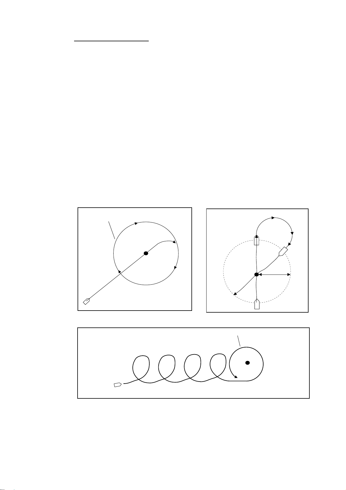
Navigating to TLL point
When TLL (Target Latitude and Longitude) data is input from a radar or echo
sounder connected in the STBY, AUTO or NAV mode, the TURN menu appears.
Then, you may choose how to progress towards that position, from ORBIT (port
direction, starboard direction) or FIGURE EIGHT. (You may also continue current
steering mode, by choosing OFF.) Also, you can set the radius of orbit on this
menu. For this mode, own ship’s position L/L data and waypoint L/L data are
required.
ORBIT
The boat makes circles around the TLL point.
SPIRAL
The boat goes to the TLL point spirally. After arriving to the TLL, the boat begins
orbiting around there.
FIGURE EIGHT
The boat automatically returns to the TLL position when it goes more than a
distance (set on menu) away from the TLL position.
Orbit around the TLL
Orbit maneuver
TLL
TLL
Distance set
on menu
Figure eight maneuver
Orbit around the TLL
TLL
Spiral maneuver
TLL navigation
3-15
Page 32
3. STEERING MODES
3.5 REMOTE Mode
Four types of optional remote controllers may be connected to the
NAVpilot-511/520/611. These are used to operate the Navpilot-511/520/611 from
a remote location.
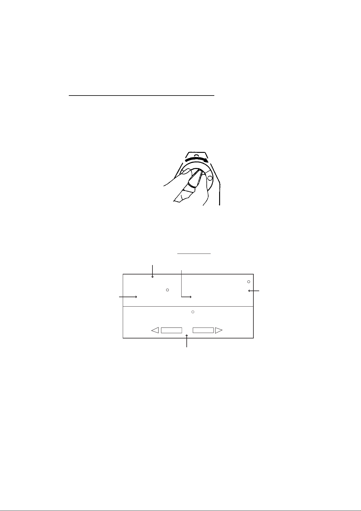
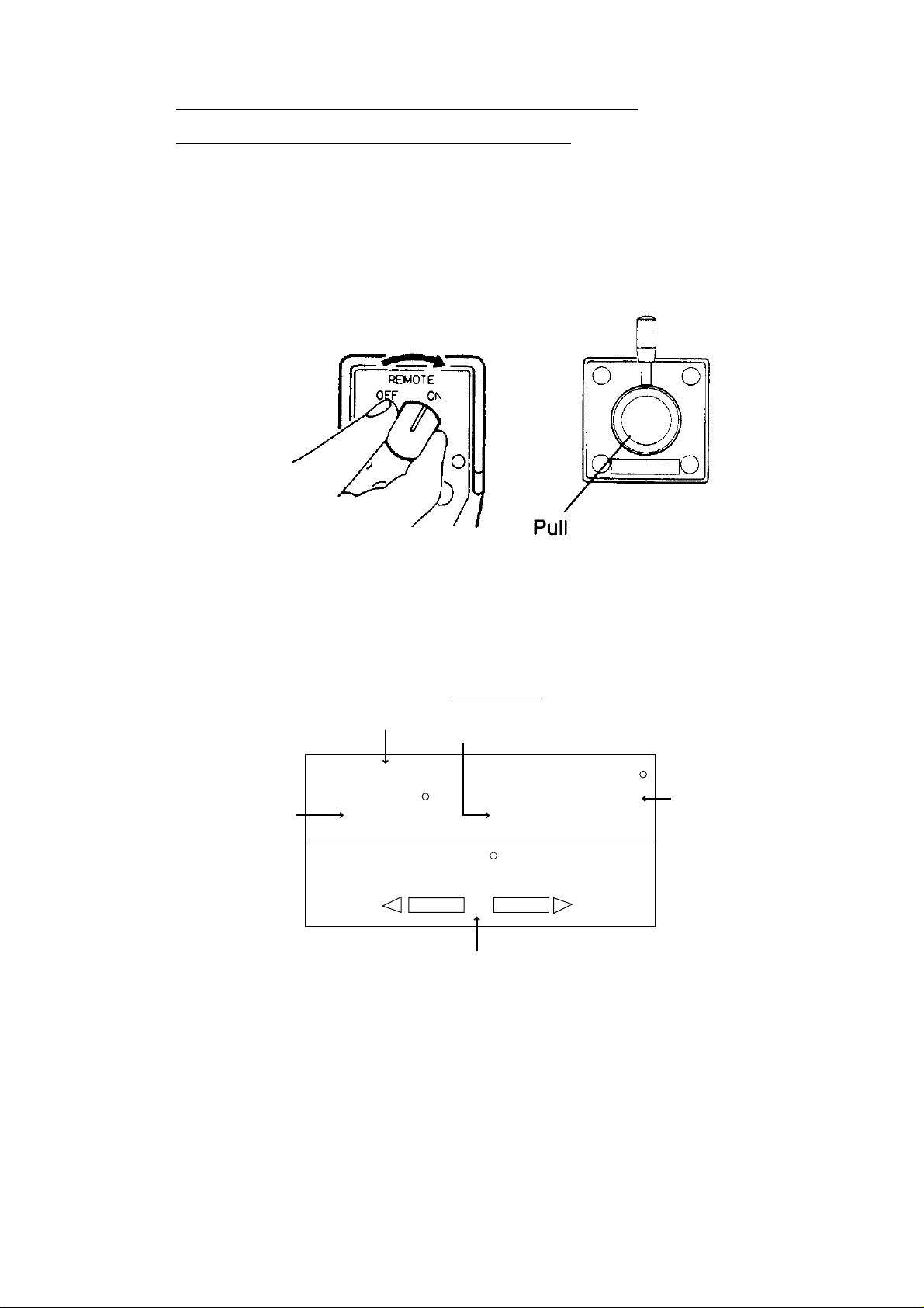
Dial type remote controll er (FAP-5551, 5552)
This remote controller can only be used when in the AUTO or NAV mode.
1. Turn on the remote controller switch to show “FU” (Follow-Up) on the control
unit. If the remote controller switch is turned on when in the STBY mode, a
beep sounds to alert you that remote mode is not avai lable.
Course set
FU (Follow-Up) mode display (dial remote controller)
Turning power on (dial type)
FU mode
(Follow-up)
FU
359
RUDDER
Heading mode
M: Magnetic
T: True
HDG
359.9
M
0
20
40
10
Rudder angle (XTE or Deviation)
40
10
20
Heading from
heading sensor
3-16
Page 33
3. STEERING MODE
FU is one of auto steering modes, which outputs an absolute value determined
with the course control knob to drive the rudder, thus changing the ship’s course
at a given rate of change towards a set point..
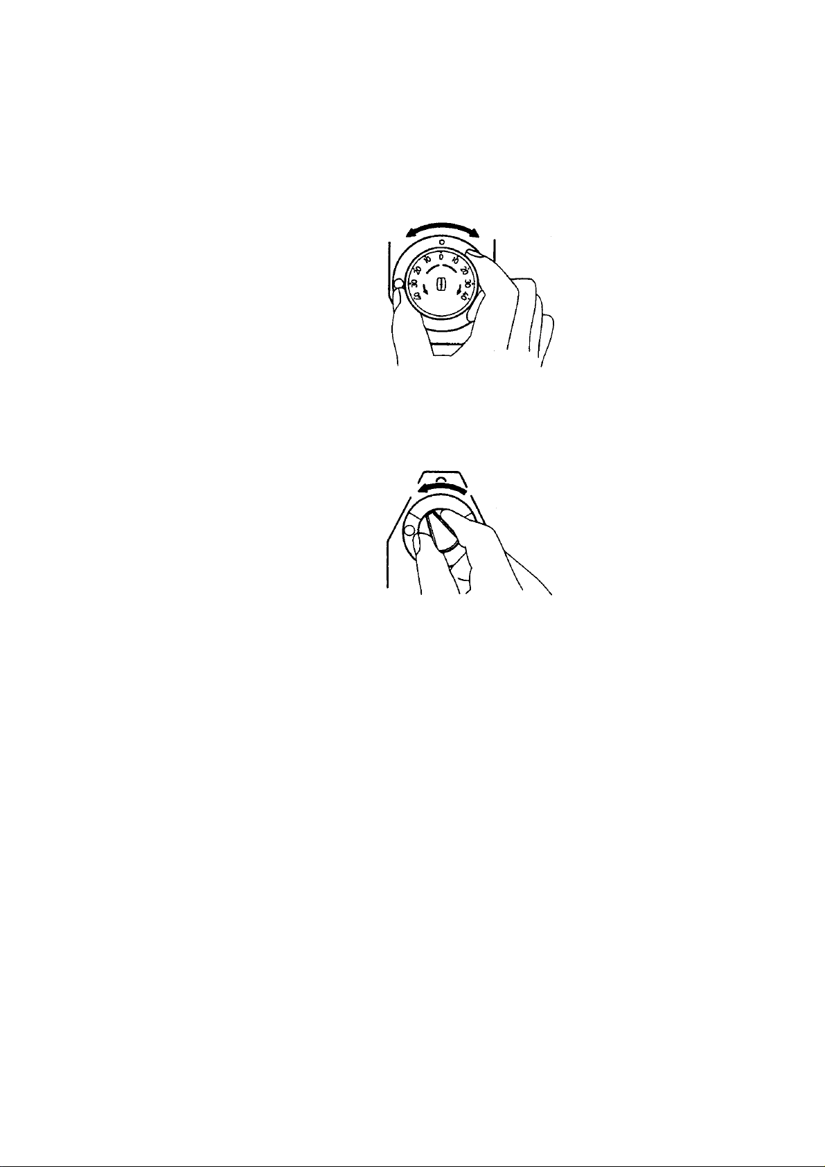
2. Rotate the dial on the remote controller to set the rudder angle.
The angle must be more than 10°, otherwise no steering will occur.
Rotating dial
3. When you terminate the REMOTE mode, turn off the remote controller.
Turning power off (dial type)
Control is returned to the main control unit and the mode that was originally
active (AUTO or NAV) is restored. For the NAV mode, the boat will go to the
destination waypoint based on the (COURSE or XTE) Nav steering method
menu setting See paragraph 3.3.2. for an explanation of this setting.
3-17
Page 34
3. STEERING MODES
Button (FAP-6211, 6212), Lever (FAP-6221, FAP-6222),
Dodge (FAP-6231, 6232) type remote controller
These controllers may be used in the STBY, AUTO and NAV modes.
1. For button and lever type remote controllers, turn on the remote controller
power.
The dodge type remote controller doesn’t have the power switch, it can be
operated by simply pressing the direction buttons.
Turning power on, button and lever ty pe remote controllers
The indication “NFU” (No Follow-Up) appears on the control unit. (For dodge
type, NFU appears while a direction key on it is pressed.)
FU mode
(Non Follow-up)
NFU
Course set
359
RUDDER
Heading mode
M: Magnetic
T: True
HDG
359.9
M
Heading from
heading sensor
0
20
40
10
Rudder angle (XTE or Deviation)
NFU (No Follow-Up) mode display
Non-Follow up (NFU) is a manual steering mode that moves the rudder as long
as the button or lever is pressed.
40
10
20
3-18
Page 35
3. STEERING MODE
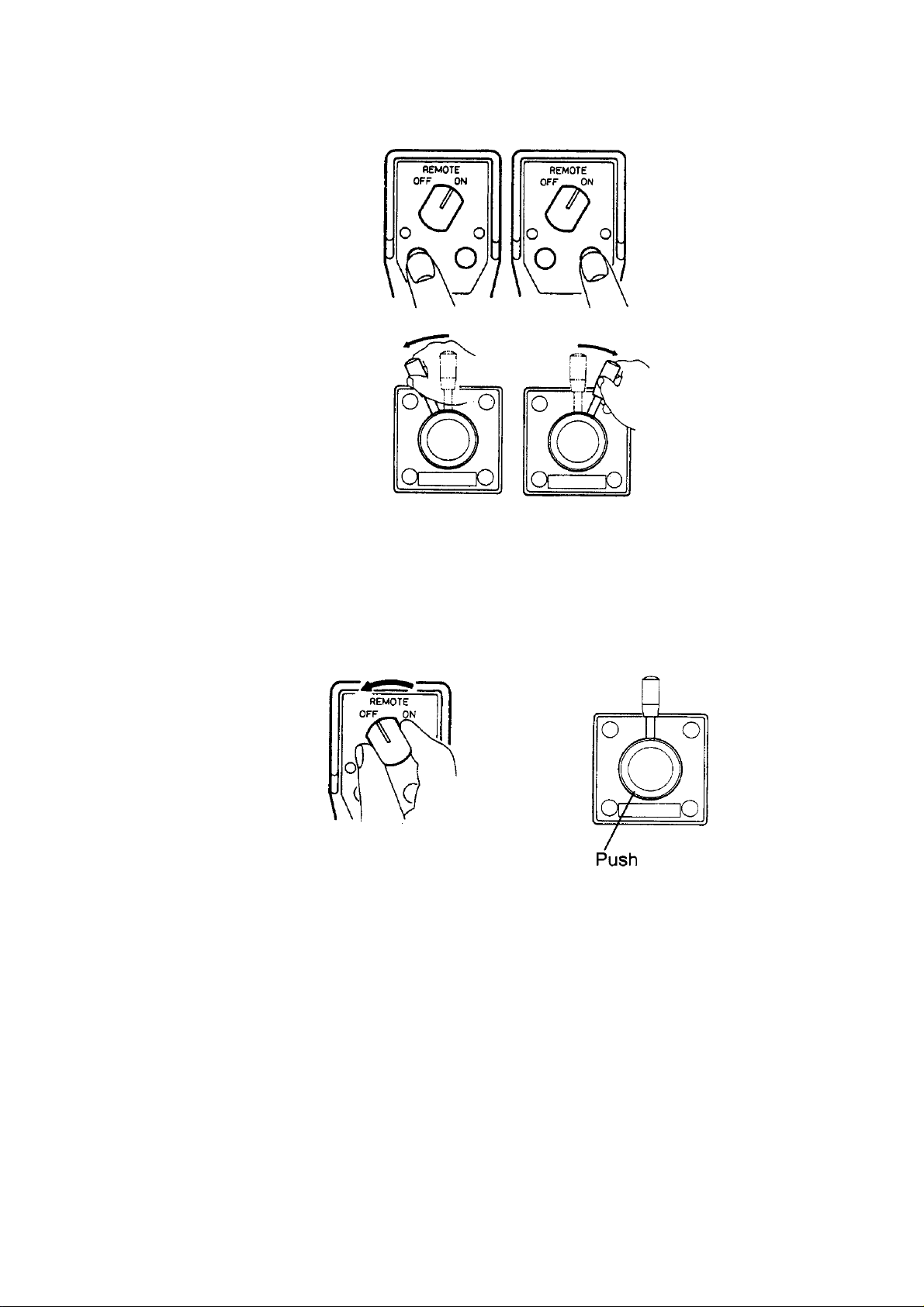
2. For button and dodge remote controllers, press the [PORT] or [STBD] key on
the remote controller. For the lever type, position the lever for the direction.
Operating remote controller (ex. button and lever ty pes)
3. For the button and lever type remote controllers, turn off the remote controller
to terminate the REMOTE mode. (For dodge type remote controller, simply
release a key.) Control is returned to the control unit and the previously used
mode (STBY, AUTO or NAV) is restored.
Turning power off, button and lever type remote cont rollers
3-19
Page 36
3. STEERING MODES
3.6 DODGE Mode
The DODGE mode is useful in situations where you need to quickly take control
of the helm to avoid an obstruction.
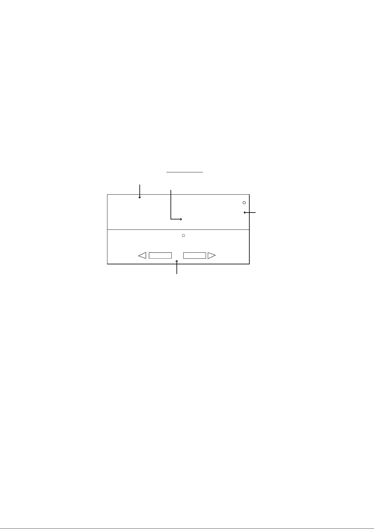
3.6.1 Dodging in STBY mode
1. Press the [PORT] or [STBD] key down to steer appropriately until the boat
finishes the turning.
The equipment goes into the DODGE mode while pressing the [PORT] or
[STBD] key. In this mode, steering can not be done from other control units or
remote controllers. Further the audible alarm sounds when one of the above
keys is operated, to alert you to dodge operation. Note also that “DODG”
appears on the display.
DODGE mode
Heading mode
M: Magnetic
T: True
DODGE
RUDDER
HDG
359.9
M
Heading from
heading sensor
0
20
40
10
Rudder angle (XTE or Deviation)
Dodge mode display 1
Note: To move the rudder to 0° point, press the [PORT] and [STBD] keys at the
same time.
2. Release the [PORT] or [STBD] key to leave from the DODGE mode.
40
10
20
3-20
Page 37
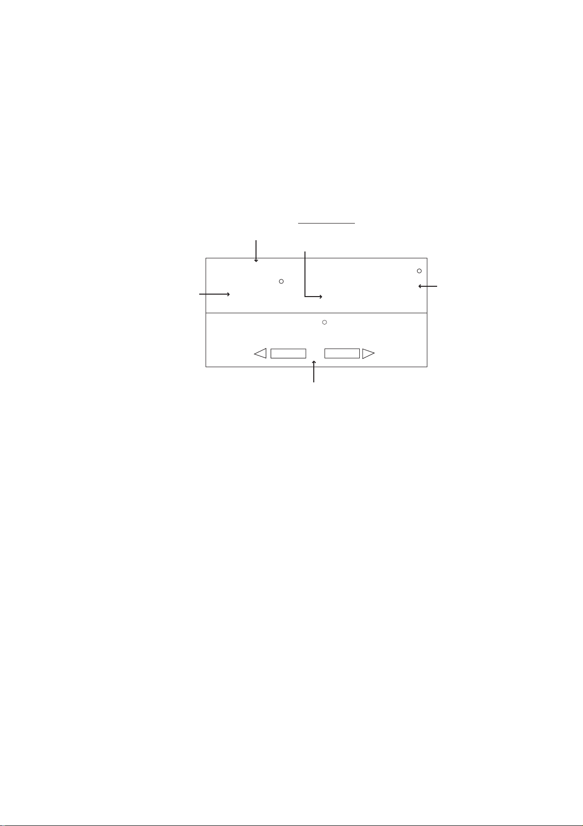
3.6.2 Dodging in AUTO or NAV mode
1. Press the [PORT] or [STBD] key down to change the course until the boat
finishes to avoid the obstruction.
The equipment goes into the DODGE mode and the audible alarm sounds when
one of the above keys is operated, to alert you to dodge operation. Note also
that “DODG” appears on the display.
Note: Press the [PORT] and [STBD] keys together to fix the course setting
value.
Heading mode
DODGE mode
M: Magnetic
T: True
3. STEERING MODE
DODGE
Course set
359
RUDDER
HDG
359.9
M
Heading from
heading sensor
0
20
40
10
Rudder angle (XTE or Deviation)
Dodge mode display 2
2. Release the key pressed to return to the previous mode (A UTO or NAV).
You can operate the autopilot with the status before the DODGE mode.
Note: In the AUTO mode, the [PORT] and [STBD] keys can be used to change
the course degree by 5°, 10° or 20° steps depending on the installation
setting. It is useful when you need to affect a large course change r apidly.
However, the DODGE mode becomes inoperative when this function is
activated. For details, ask your serviceman.
40
10
20
3-21
Page 38

3. STEERING MODES
This page is intentionally left blank.
3-22
Page 39

4. MENU OPERATION
Most settings are carried out in the menus. The items shown in each menu depend on the
mode in use. For the STBY mode the complete menu is shown. W hen the menu is
accessed while in either the AUTO or NAV modes, only the menu items that are most
frequently used in those modes are shown.
The ALARM SETUP menu description is shown on Chapt er 5.
4.1 STBY Mode Menu
While in the STBY mode, press the [TURN/MENU] key twice to show the STBY mode menu.
This menu shows all of the Navpilot-511/520/611’s menu items.
MESSAGE
CONTRAST/BRILLIANCE
ALARM SETUP
PARAMETER SETUP
SYSTEM SETUP
TEST: OFF
SYSTEM DATA
STBY mode menu
4-1
Page 40
4. MENU OPERATION
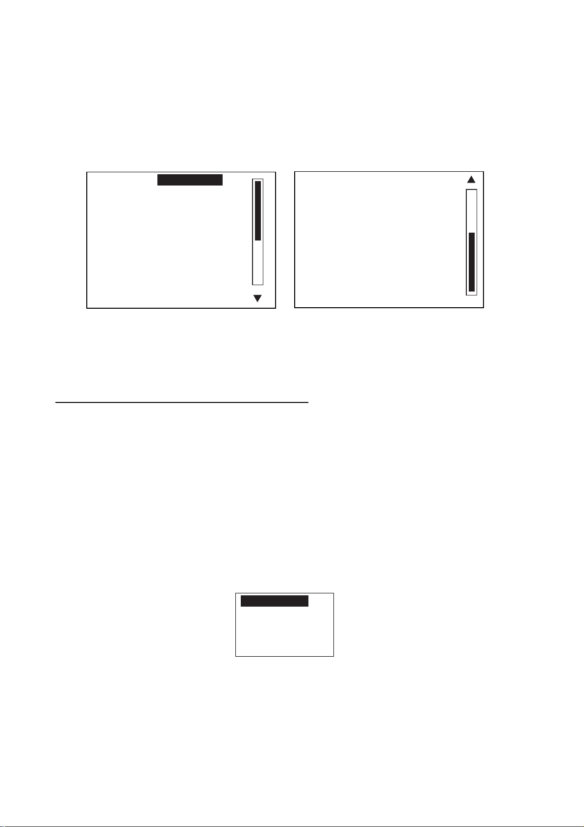
4.1.1 Setting parameters
The PARAMETER SETUP menu sets various parameters for the control of the
NAVpilot-511/520/611.
1. In the STBY mode, press the [TURN/MENU] key twice to open the STBY mode menu.
2. Rotate the course control knob to select “PARAMETER SETUP”.
3. Press the course control knob to show the PARAMETER SETUP menu.
SEA STATE:
DEVIATION LEVEL: AUTO
MANUAL PARAMETERS
AUT O TRIM: ON 40
ADVANCED AUTO: OFF
AUTO NET TOWING : OFF
NAV MODE: XTE
FULL-AUTO
Page 1
NAV SRC: PORT 1
RADIUS OF ORBIT: 0.50 nm
SPIRAL SPEED: 1.0 kt
FISH MODE: OFF
WAYPOINT SWITCHING: AUTO
SPD CALC.: SOG
PUSH MENU KEY TO RETURN
TO PREVIOUS MENU.
Page 2
Parameter setup menu
4. To close the PARAMETER SETUP menu, press the [TURN/MENU] key twice.
Selecting the method of entering the parameter
The NAVpilot-511/520/611 has an automatic adjustment feature which sets up the
equipment according to ship’s characteristics and sea state for optimum performance in the
AUTO and NAV modes. In addition, a self-learning algorithm is incorporated: Parameters for
rudder ratio, counter rudder and auto trim gains are constantly optimized based on the
steering history of your boat, and are stored in memory for future navigation.
You choose how the NAVpilot-511/520/611 will steer the vessel, (manual or autom atic sea
state parameter adjustment) as follows:
1. Rotate the course control knob to select “SEA STATE” from the PARAMETER SETUP
menu.
2. Press the course control knob to show the sea state options window.
FULL-AUTO
SEMI-AUTO
MANUAL-CALM
MANUAL-MODERATE
MANUAL-ROUGH
Sea state options window
4-2
Page 41

4. MENU OPERATION
3. Rotate the course control knob to select FULL-AUTO, SEMI-AUTO, MANUAL-CALM,
MANUAL-MODERATE or MANUAL-ROUGH as appropriate, and then press the course
control knob.
FULL-AUTO: Auto adjustment and self-learning are on.
SEMI-AUTO: Auto adjustment is on, self-learning is off.
MANUAL-CALM: Self-learning is off, using the parameter selected for calm sea.
MANUAL-MODERATE: Self-learning is off, using the parameters for a typical normal sea
state.
MANUAL-ROUGH: Self-learning is off, using preset parameters for a typical rough sea
state.
For normal, everyday operation, the FULL-AUTO mode is recommended. However, if you
want the NAVpilot-511/520/611 to steer the boat based on experience-related parameters,
but you don’t want the pilot to be in “self-learning” mode, choose the SEMI-AUTO option.
Note that the course keeping quality may be decreased if the sea state is different from the
experience-related parameters. This option is provided if you happen to be using the pilot in
a situation that you do not anticipate encountering again.
4. When selecting “FULL-AUTO” at step 3, set DEVIATION LEVEL as follows:
a) Rotate the course control knob to select “DEVIATION LEVEL”.
b) Press the course control knob to show the deviation level options window.
AUTO
LEVEL
Deviation level options window
c) Rotat e the course control knob to select “AUTO” or “LEVEL” as appropriate. For LEVEL,
you may set a value between 1 and 9. A lower number keeps the course more exactly,
but the rudder may be turned more often. W ith a higher number, the rudder is fixed, but
the course may not be kept as accurately.
d) Press the course control knob twice to close the window.
4-3
Page 42
4. MENU OPERATION
Setting parameters manually
When MANUAL-CALM, MODERATE or ROUGH is selected at the previous paragraph, set
MANUAL PARAMETERS as below.
You can set three parameters for MANUAL function: Weather, Rudder gain and Counter
rudder.
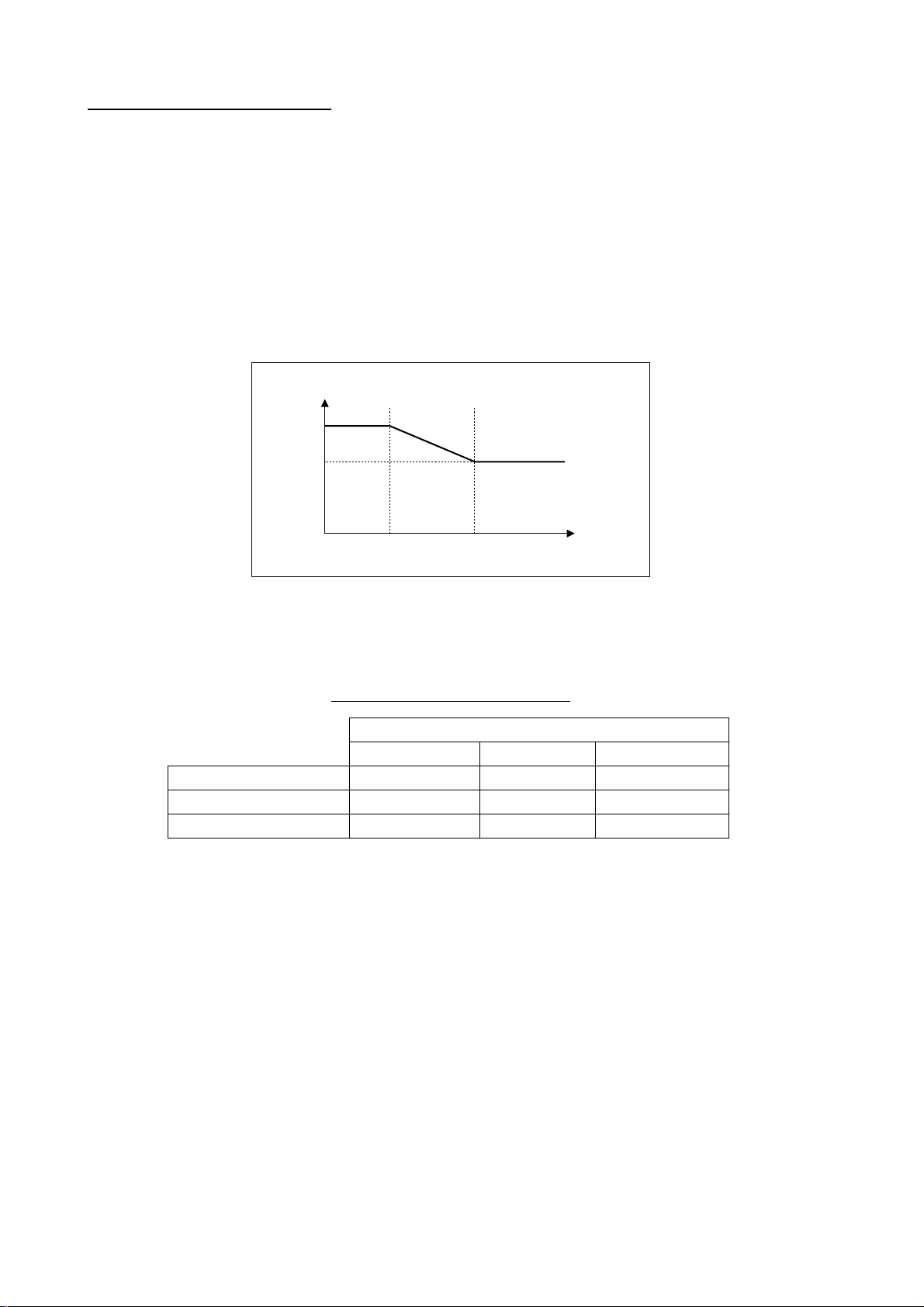
The default manual parameters provide for co mfortable steering of a boat 35 feet in length
at the speed of 10 kt. When speed is increased to 20 kt, the manual p ara meters are
automatically reduced 66%.
Parameter setting
100%
66%
10 kt
20 kt
Ship's speed
1. Rotate the course control knob to select MANUAL PARAMATERS from the
PARAMETER SETUP menu.
2. Press the course control knob to show the following table.
Example of Manual parameter
SEA STATE
CALM MODERATE ROUGH
WEATHER 1° 2° 3°
RUDDER GAIN 0.4 0.5 0.6
COUNT RUDDER 0.2 0.3 0.4
Refer to the followings to set parameters:
Boat longer than 35 feet: Set parameters smaller than default parameters.
Boat shorter than 35 feet: Set parameters larger than default parameters.
3. Rotate the course control knob to choose WEATHER-CALM setting, and then press the
course control knob.
4. Rotate the course control knob to set value (Setting r ange: 1° to 10° for weather).
5. Press the course control knob.
6. Set WEATHER-MODERATE, WEATHER-ROUGH and RUDDER GAIN and COUNT
RUDDER similarly (Setting range: 0.1 to 2.0 for rudder gain, 0.1 to 4.0 for counter
rudder).
7. Press the [MENU] key to close the table.
4-4
Page 43
4. MENU OPERATION
WEATHER
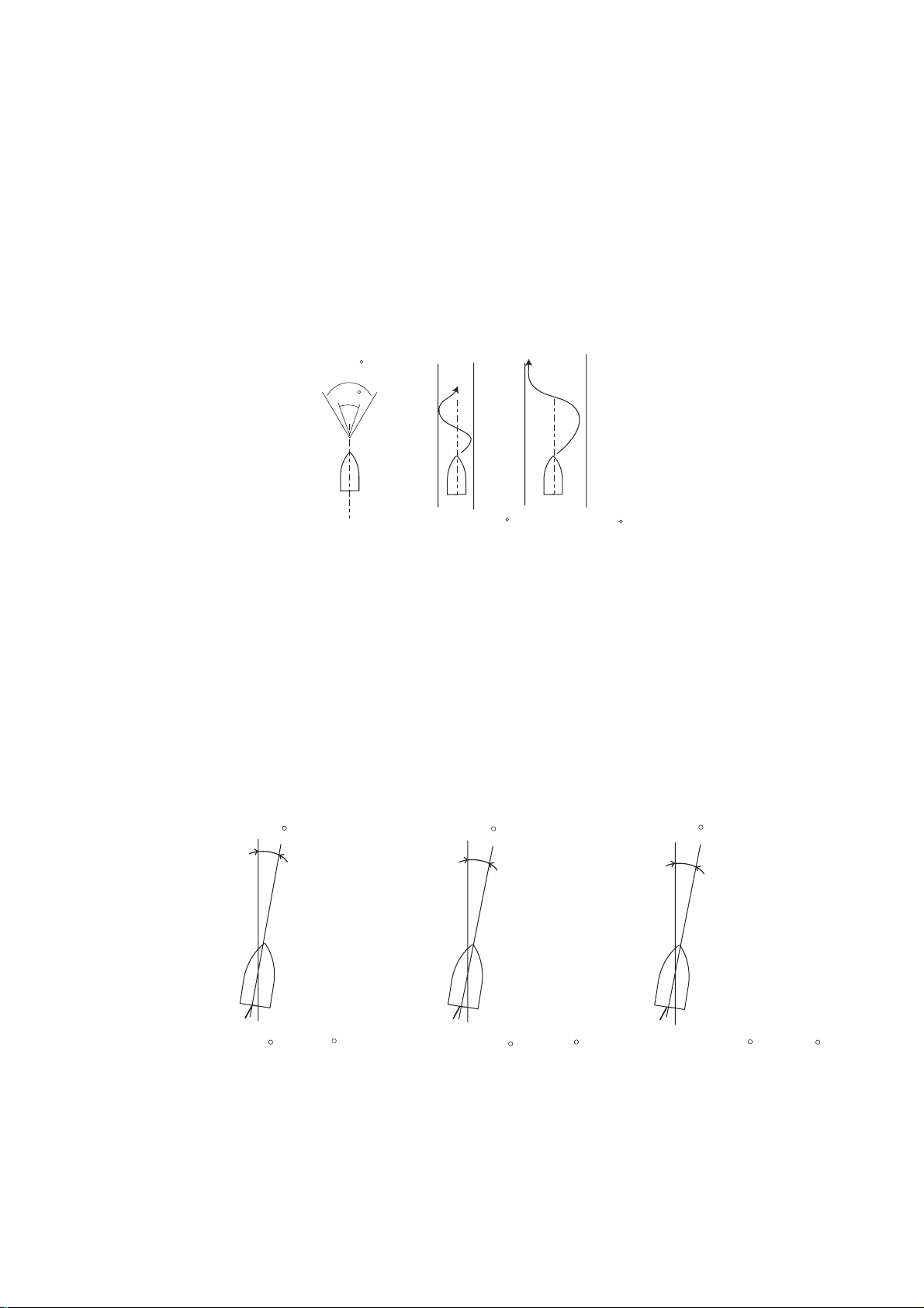
When the sea is rough, the boat’s heading fluctuates to port and starboard. If the rudder is
driven very often to maintain the set course, the helm mechanism may wear out. To prevent
this, the weather adjustment m akes the NAVpilot-511/520/611 insensitive to minute course
deviations. You may choose a degree between 1° to 10°. Unt il the course deviation exceeds
the selected setting, steering to correct the heading will not be initiated.
The illustration below shows boat’s track lines with weat her setting 3° and 7°. When 7° is
set, for example, the rudder is not driven until t he course deviation exceeds 7°. Increasing
the setting reduces activation of t he steering gear, however the boat tends to zigzag. W hen
the sea is calm, set a smaller value.
7
3
Weather = 3 Weather = 7
Track line and weather sett ing value
RUDDER GAIN
When the boat’s heading deviates from the set course, t he NAVpilot-511/520/611 adjusts
the rudder to correct it. The rudder angle (number of degrees) which is st eered against
every degree of course deviation is known as the rudder gain.
The following illustrations show how many degrees the NAVpilot-511/520/611 steers the
rudder in order to nullify 10 degrees of course deviat ion with various set tings of the rudder
gain.
Rudder gain = 0.1
10
Rudder gain = 0.3
10
Rudder gain = 0.8
10
Rudder angle = 10 x 0.1=1
Rudder angle = 10 x 0.3= 3
Rudder angle = 10 x 0.8= 8
Rudder angle and rudder gain setting
4-5
Page 44
4. MENU OPERATION
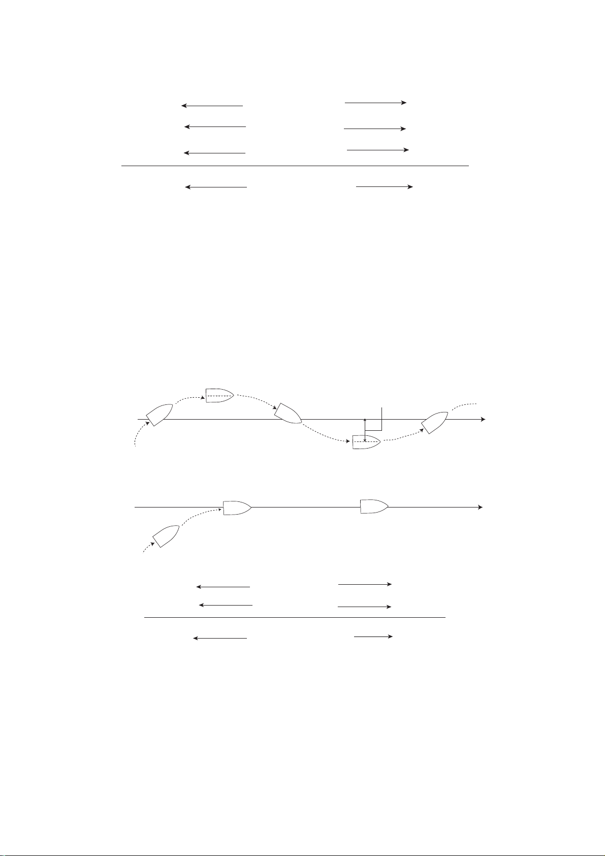
Set rudder gain so that the boat does not make frequent yaw. The figure shown below
provides general guidelines for setting rudder gain.
fast
calm
light
low
Boat's Speed
Sea State
Load Condition
RUDDER GAIN
slow
rough
heavy
high
General guidelines for setting rudder gain
COUNTER RUDDER
If the boat is heavily loaded, the heading could change excessively because of inertia. This
phenomenon causes the vessel to “overshoot” the int ended course. If this happens, the
NAVpilot-511/520/611 will steer the rudder to the opposite side and t he heading will turn in
opposite direction excessively again. In an extreme case t he heading oscillates several
times until it finally settles in the new course. An adjustment known as “counter rudder”
prevents this kind of oscillation.
Counter rudder is usually not required for small boats. W hen your boat zigz ags a lot before
settling in the new course, increase the counter rudder setting.
Counter rudder:
small setting
Counter rudder:
proper setting
Large course error
The counter rudder feature functions to smoothly
return ship's heading toward intended course.
slow
light
low
Boat's Speed
Load Condition
COUNTER RUDDER
fast
heavy
high
General guidelines for setting counter rudder g ain
Intended
course
4-6
Page 45

4. MENU OPERATION
Adjusting the sensitivity in mon itoring the boat’s trim
The NAVpilot-511/520/611 continually monit ors t he boat’s trim in order to keep t he trim
sensitivity optimum. A lower setting is common because boat’s trim usually does not change
quickly. A large number changes the trim com pensation value more frequently. Too high of a
setting may result in the following problems.
• Trim sensitivity is over-affected, resulting that a trim appears in both port and starboard
directions alternately.
• Trim compensation mechanism responds to the yawing, resulting in more serious
oscillation of ship’s heading.
To set the auto trim sensitivity:
1. Rotate the course control knob to select AUTO TRIM from the PARAMETER SETUP
menu.
2. Press the course control knob to show the auto trim options window.
OFF
ON
Auto trim options window
3. Rotate the course control knob to select “ON”.
4. Press the course control knob.
5. Rotate the course control knob to select current value.
6. Press the course control knob and the current value is circumscribed with a double
rectangle.
7. Rotate the course control knob to set value (Setting range: 1 to 100, the default setting
is calculated automatically dependin g on the ship’s length entered on t he DOCK SIDE
SETUP menu.)
8. Press the course control knob to finish.
4-7
Page 46
4. MENU OPERATION
When towing the net
When a boat is in tow of the fishing gear, its stern is “dragged” by the net. This causes the
boat to stray from its intended course. To keep the boat on course, you need to adjust t he
trim manually, which can be bothersome. If you do not want to be bothered with trim
adjustments, you can enable the automatic towing function to have the trim automatically
adjusted. This feature is very valuable for tr awlers and purse seiners.
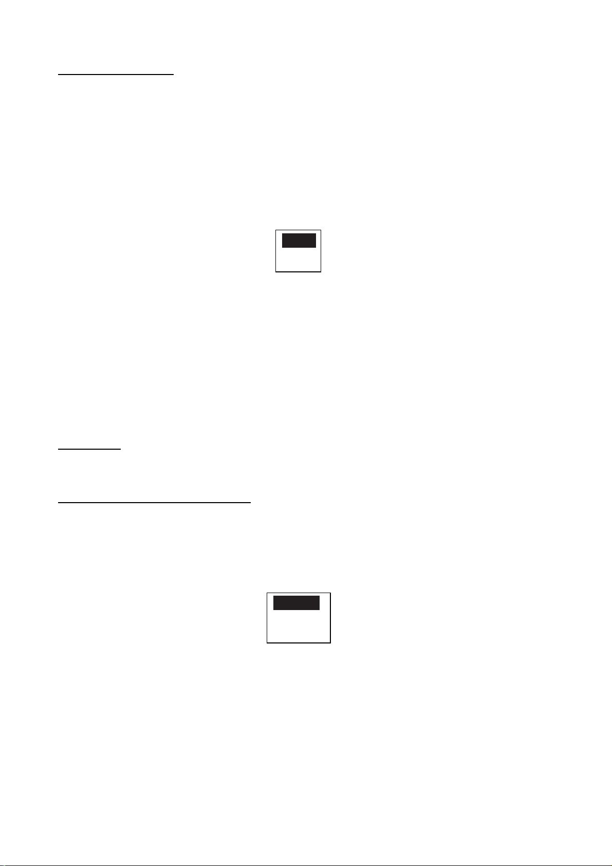
1. Rotate the course control knob to select “AUTO NET TOWING” from the PARAMETER
SETUP menu.
2. Press the course control knob to show the net towing options window.
OFF
ON
Auto net towing options window
3. Rotate the course control knob to select ON or OFF as appropriate.
4. Press the course control knob to finish.
If the AUTO NET TOWING setting is done on the AUTO mode menu, press the [STBY] key
to go into STBY mode and then press the [STBY] key to return to the AUTO mode to
activate this function.
Note that you must keep the boat on a straight course before the AUTO mode is selected.
NAV MODE
See the paragraph 3. 3. 2. "Selecting sailing m ethod of NAV mode".
Selecting the navigator connected
When two navigators are connected, you can s elect one appropriately.
1. Rotate the course control knob to select "NAV SRC" from the PARAMETER SETUP
menu.
2. Press the course control knob to show the nav mode data source window.
PORT 1
PORT 2
BOTH
Nav mode data source window (ex. default setting)
3. Rotate the course control knob to select PORT 1*, PORT 2* or BOTH as appropriate.
For “BOTH”, Navpilot-511/520/611 uses the port input the higher priority data (See the
installation manual). If same priority data are input to the port 1 and port 2, the port 1 is
used.
4. Press the course control knob to finish.
*: Default set name. These can be changed on the installation menu.
4-8
Page 47
RADIUS OF ORBIT
See the section 3.4 "TURN Mode".
SPIRAL SPEED
See the section 3.4 "TURN Mode".
FISH MODE
See the section 3.4 "TURN Mode".
WAYPOINT SWITCHING
See the section 3.3.3 "Switching waypoint".
Selecting speed format
You can choose speed format among from SOG, STW and MANUAL.
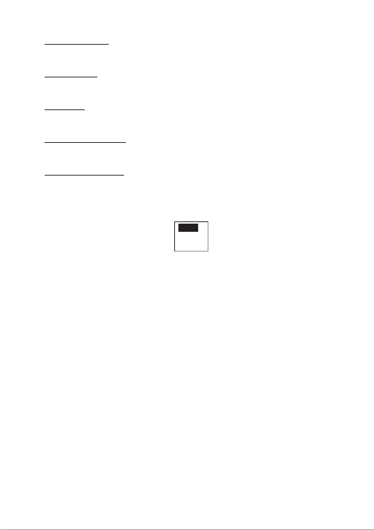
1. Rotate the course control knob to select "SPD CALC."
2. Press the course control key to show the speed calculation window.
4. MENU OPERATION
SOG
STW
MANUAL
Speed calculation wi ndow
3. Rotate the course control knob to select SOG, STW or MANUAL as appropriate.
When selecting MANUAL, enter the speed manually.
4. Press the course control knob to finish.
The NAVpilot-511/520/611 controls the boat (for ORBIT, SPIRAL function, etc.) by using the
speed selected here. When MANUAL is selected and there is a large difference between
actual and entered speeds, the boat may not be controlled correctly. We recommend using
of GPS speed.
4-9
Page 48
4. MENU OPERATION
4.1.2 Setting other menu items
The SYSTEM SETUP menu allows you to set various item according to your operating
needs.
1. Open the STBY mode menu.
2. Rotate the course control knob to select “SYSTEM SETUP”.
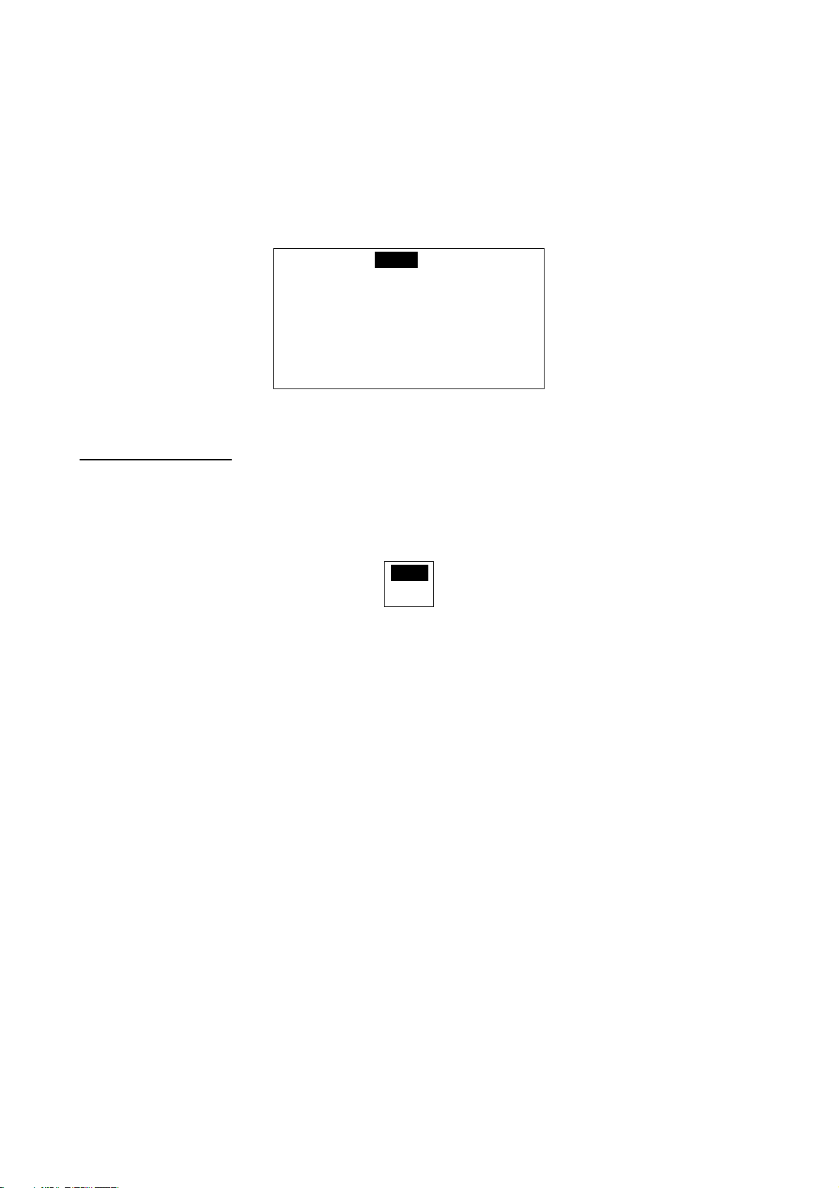
3. Press the course control knob to show the SYSTEM SETUP menu.
KEY BEEP:
LOCK: UNLOCK
PANNEL DIMMER: 1
PUSH MENU KEY O RETURN
TO PREVIOUS MENU.
OFF
System setup menu
Activating key beep
Turn the key beep on or off.
1. Rotate the course control knob to select “KEY BEEP” on the SYSTEM SETUP menu.
2. Press the course control knob to show the key beep options window.
OFF
ON
Key beep options window
3. Rotate the course control knob to select ON or OFF as appropriate.
4. Press the course control knob.
4-10
Page 49

4. MENU OPERATION
Locking the control unit
The LOCK feature renders the following commands inoperative from the control unit at
which the LOCK feature has been actuated.
• Menu operation
• Changing the steering mode
• Course setting
• Waypoint switching
1. Rotate the course control knob to select “LOCK” from the SYSTEM SETUP menu.
2. Press the course control knob to show the lock options window.
UNLOCK
LOCK
Lock options window
3. Rotate the course control knob to select “LOCK” or “UNLOCK” as appropriate.
4. Press the course control knob.
To unlock, press the [STBD] (►) key while holding the [TURN/MENU] key down.
4-11
Page 50

4. MENU OPERATION
Setting the panel dimmer
You can adjust the control panel dimmer as follows.
1. Rotate the course control knob to select “PANEL DIMMER” from the SYSTEM SETUP
menu.
2. Press the course control knob and the current value is circumscribed with a double
rectangle.
3. Rotate the course control knob to set value (Setting range: 1 to 8). The higher the
number the greater the illumination.
4. Press the course control knob.
4-12
Page 51
5. ALARMS
5.1 ALARM SETUP Menu
The NAVpilot-511/520/611 has seven conditions which generate both audio and
visual alarms: watch alarm, deviation alarm. XTE (cross-track error) alarm,
speed alarm, depth alarm , t em p alarm and log trip alarm. You may set up the
alarms on the ALARM SETUP menu.
1. Press the [TURN/MENU] key twice to show the mode menu.
2. Rotate the course control knob to select “ALARM SETUP”.
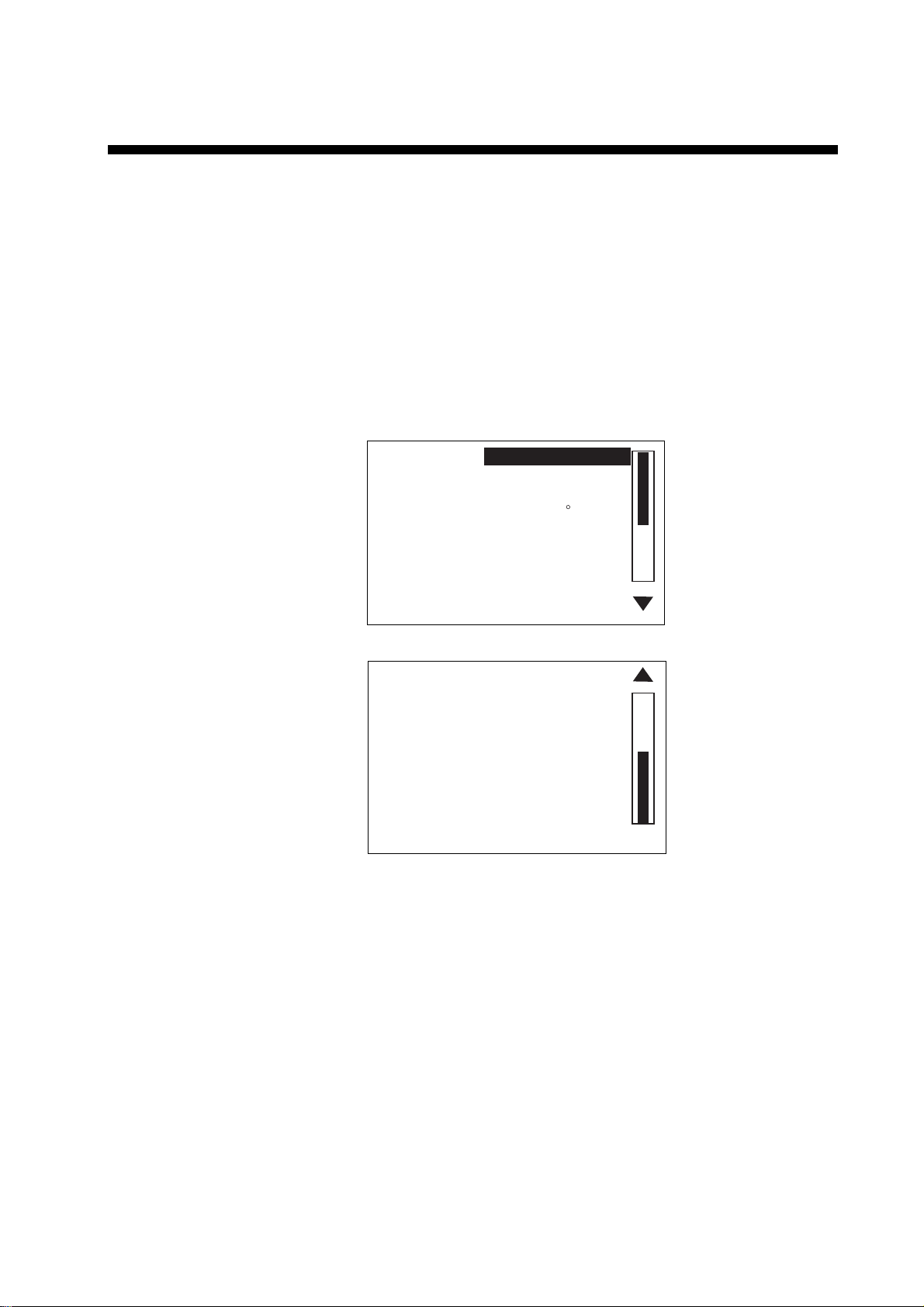
3. Press the course control knob to show the ALARM SETUP menu.
Page 1
AUDIO:
ALARM INTERVAL: SHORT
WATCH ALARM: OFF
DEVIATION ALARM: 90
XTE: OFF
SPD: OFF
DPT: OFF
Page 2
TMP: OFF
TRIP LOG ALARM: OFF
CLEAR TRIP LOG: NO
PUSH MENU KEY TO RETURN
TO PREVIOUS MENU.
INTERNAL BUZZER
Alarm setup menu
4. Press the [TURN/MENU] key to close the ALARM SETUP menu.
5-1
Page 52
5. ALARMS
5.1.1 Selecting the alarm buzzer
You may choose the buzzer from which to output t he audio alarm as follows.
Use the external buzzer connected to the proce ssor unit if the internal buzzer
volume is small.
Note: If “INTERNAL + EXTERNAL” is selected, the external buzzer sounds
when turning the NAVpilot-511/520/611 off.
1. Rotate the course control knob to select “AUDIO” from the ALARM SETUP
menu.
2. Press the course control knob to show the audio alarm options window.
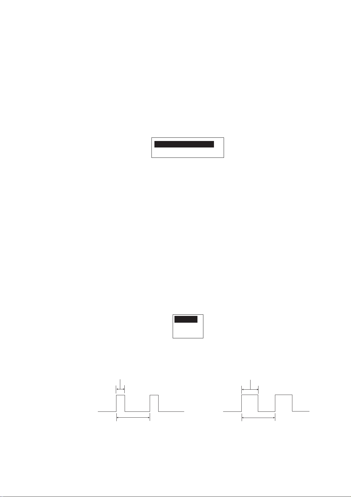
INTERNAL BUZZER
INTERNAL +EXTERNAL
Audio alarm options window
3. Rotate the course control knob to select INTERNAL BUZZER or
INTERNAL+EXTERNAL as appropriate.
INTERNAL BUZZER: Sounds the buzzer in the control unit.
INTERNAL+EXTERNAL BUZZER: Sounds the control unit buzzer and external
buzzer if connected.
4. Press the course control knob.
5.1.2 Selecting the beep pattern
The sound pattern of the audio alarm (WATCH ALARM, DEVIATION ALARM,
XTE ALARM, SPEED ALARM, DEPTH ALARM and TEMP ALARM) can be
selected as follows.
1. Rotate the course control knob to select “ALARM INTERVAL” from the
ALARM SETUP menu.
2. Press the course control knob to show the alarm interval options window.
SHORT
LONG
CONTINUE
Alarm interval options window
3. Rotate the course control knob to select SHORT, LONG or CONTINUE as
appropriate.
200 ms
LONG pattern
SHORT pattern
800 ms
400 ms
800 ms
CONTINUE: Beep sounds continuously.
4. Press the course control knob.
5-2
Page 53

5.1.3 Setting the watch alarm
The watch alarm periodically warns the helmsman to check the autopilot when in
the AUTO or NAV mode.
1. Rotate the course control knob to select “WATCH ALARM” from the ALARM
SETUP menu.
2. Press the course control key to show the watch alarm options window.
OFF
ON
Watch alarm options window
3. Rotate the course control knob to select “ON” or “OFF” as appropriate.
When selecting “ON”, you can set the time interval (1 to 10 min) at which to be
alerted. If the set time passes without operation, the alarm sounds. Further, if
three minutes elapse after the watch alarm has sounded, the message “TOUCH
ME” appears. Press any key to clear the alarm.
4. Press the course control knob.
5.1.4 Setting the heading deviation alarm
5. ALARMS
The deviation alarm sounds when the heading deviates more than a limit set
than the current heading in the AUTO or NAV mode.
1. Rotate the course control knob to select “DEVIATION ALARM” from the
ALARM SETUP menu.
2. Press the course control knob and the current value is circumscribed with a
double rectangle.
3. Rotate the course control knob to set the degree of devi ation (Setting range:
1 to 90°).
4. Press the course control knob.
5-3
Page 54

5. ALARMS
5.1.5 Setting the cross-track error limit
When in the NAV mode, the XT E alarm will sound when the course err or has
exceeded or fails within the range set in the following steps:
1. Rotate the course control knob to select “XTE” from the ALARM SETUP
menu.
2. Press the course control knob to show the XTE alarm options window.
OFF
ON
XTE alarm options window
3. Rotate the course control knob to select “OFF” or “ON” as appropriate.
OFF: Turn the XTE alarm off.
ON: The alarm is released when exceeding the XTE range is exceeded.
For ON, set the range (0.001 to 9.999 nm/km/sm) using the course control knob.
4. Press the course control knob.
5-4
Page 55

5.1.6 Setting the speed alarm
The speed alarm warns you when your boat’s speed is within, outside, over or
under the speed range setting.
1. Rotate the course control knob to select “SPD” from the ALARM SETUP
menu.
2. Press the course control knob to show the speed alarm options window.
Speed alarm options window
3. Rotate the course control knob to select speed alarm condition.
OFF: Turn the speed alarm off.
UNDER: The alarm is sounded when ship’s speed is under the set value.
OVER: The alarm is sounded when the ship’s speed is over the set value.
INSIDE: The alarm released when ship’s speed is within the range set.
OUT: The alarm is released when ship’s speed is outside the range set.
When selecting INSIDE or OUT OF RANGE, set the upper and lower limits,
using three digits. For OVER and UNDER, set value (Setting range: 0.0 to 999.9
kt, km/h or mph). This alarm uses the speed set at SPEED CALICULATION on
the SYSTEM SETUP menu.
4. Press the course control knob.
OFF
UNDER
OVER
INSIDE
OUT
5. ALARMS
5-5
Page 56

5. ALARMS
5.1.7 Setting the depth alarm
The depth alarm sounds when the bottom is shallower, deeper within or outside
the range setting.
Note: To use the dept h alarm, depth data from an external sounder is required.
1. Rotate the course control knob to select “DPT” from the ALARM SETUP
menu.
2. Press the course control knob to show the depth alarm options window.
Depth alarm options window
3. Rotate the course control knob to select the condition.
OFF: Turn the depth alarm off.
SHAL. (shallow): The alarm is released when the bottom is shallower than the
value set.
DEEP: The alarm is sounded when the bottom is deeper than the value set.
INSIDE: The alarm is sounded when the bottom is within the range set.
OUT: The alarm released when the bottom is outside the range set.
When selecting INSIDE or OUT OF RANGE, set upper and lower limits, using
three digits. For SHALLOW or DEEP, set a value (Setting range: 0 to 9999.9
ft/m/FA/PB).
4. Press the course control knob.
OFF
SHAL.
DEEP
INSIDE
OUT
5-6
Page 57

5.1.8 Setting the tem perature alarm
There are five types of water temperature alarm s: UNDER, OVER, INSIDE, OUT
and CURRENT RIP. The UNDER and OVER alarms sound when the water
temperature is lower or higher than the value set , the INSIDE and OUTSIDE
alarms sound when the water temperature is within or outside the rang e set. For
CURRENT RIP, t he alarm sounds when the temperature changes over the value
set within a minute.
1. Rotate the course control knob to select “TMP” from the ALARM SETUP
menu.
2. Press the course control knob to show the temp alarm options window.
OFF
UNDER
OVER
INSIDE
OUT
CUR.
5. ALARMS
Temp alarm options window
3. Rotate the course control knob to select the water temperature condition.
When selecting the INSIDE, OUT or CUR. (current lip), set the number for upper
and lower limits. For UNDER or OVER, set a value (Setting range: 0 to 120°F or
–20 to 50°C).
4. Press the course control knob.
5.1.9 Setting the trip distance alarm
The log trip alarm alerts you a defined distance has been reac hed.
1. Rotate the course control knob to select “TRIP LOG ALARM” from the
ALARM SETUP menu.
2. Press the course control knob to show the log trip options window.
OFF
ON
Log trip options window
3. Rotate the course control knob to select “ON” or “OFF” as appropriate.
When selecting ON, set appropriate value (Setting range: 0 to 9999 nm/km/sm).
4. Press the course control knob.
5-7
Page 58

5. ALARMS
5.1.10 Clearing the trip distance
You can reset the trip distance to zero as follows.
1. Rotate the course control knob to select “CLEAR TRIP LOG” from the
ALARM SETUP menu.
2. Press the course control knob to show the log trip clear options window.
Log trip clear options window
3. Rotate the course control knob to select “YES” to reset the trip distance.
4. Press the course control knob.
NO
YES
5-8
Page 59
5.2 Alarm Information
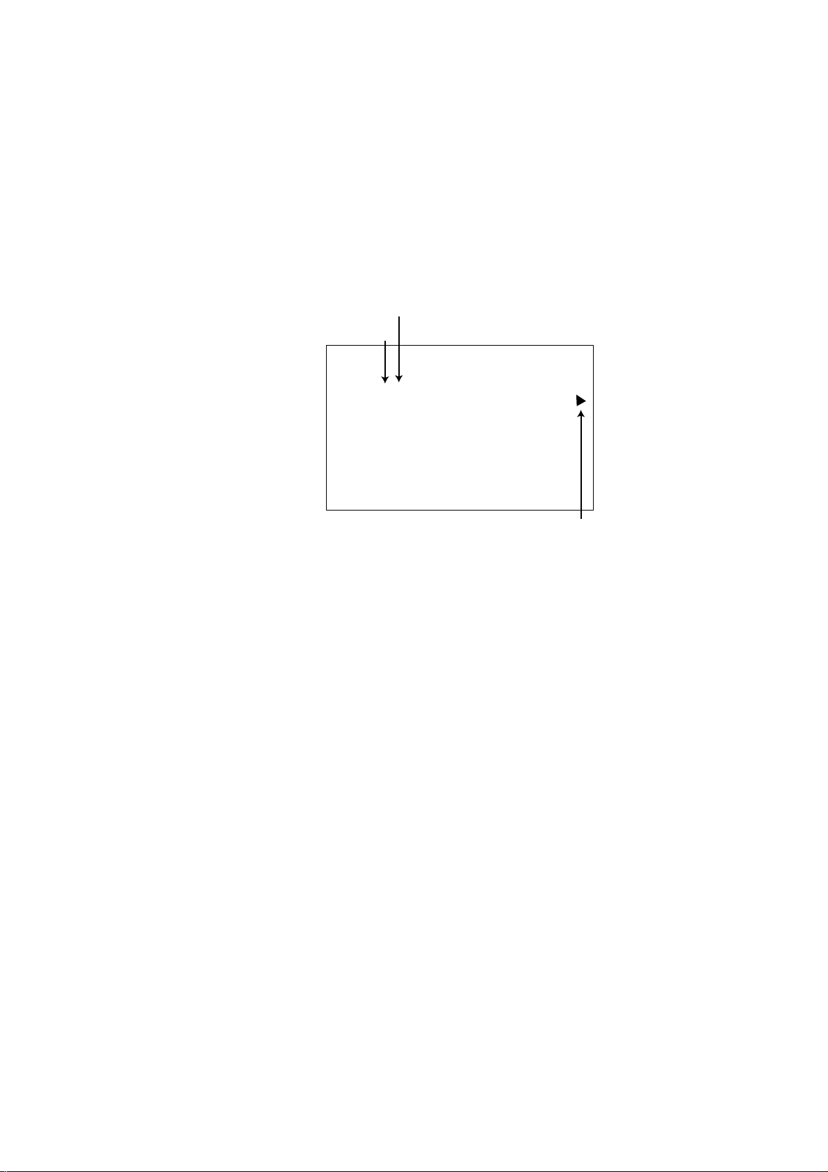
When an alarm condition occurs, the buzzer sounds and the “!” icon and alarm
type window appears on the screen. Press any key to silence alarm and hide the
window. You can see which alarm has been violated on the MESSAGE window.
In the example below the deviation alarm has been violated.
1. Press the [TURN/MENU] key twice to show the menu.
2. Rotate the course control knob to select “MESSAGE”, and then press the
course control knob to show the message window.
Total of occured alarms
Page No.
ALARM 1/2
DEVIATION ALARM CONTINUE?
5. ALARMS
MESSAGE
PUSH MENU KEY TORETURN
TO PREVIOUS MENU.
Press the appropriate key (PORT or STBD)
to show the other alarm.
Alarm menu
3. Confirm the alarm message.
4. Press the [TURN/MENU] key twice to finish.
5-9
Page 60

5. ALARMS
DEVIATION ALARM Deviation alarm has occurred. 1
CROSS TRACK ERROR XTE alarm has occurred. 2
SPEED ALARM Speed alarm has occurred. 3
DEPTH ALARM Depth alarm has occurred. 4
WATER TEMP. ALARM Temperature alarm has occurred. 5
TRIP ALARM Log alarm has occurred. 6
Alarm messages
The table below shows the alarm messages, their m eanings and priorities.
Alarm messages, their meanings and priorities
Message Meaning Priority
5-10
Page 61
6. MAINTENANCE & TROUBLESHOOTING
This chapter provides information necessary for keeping your unit in good
working order and remedying simple problems.
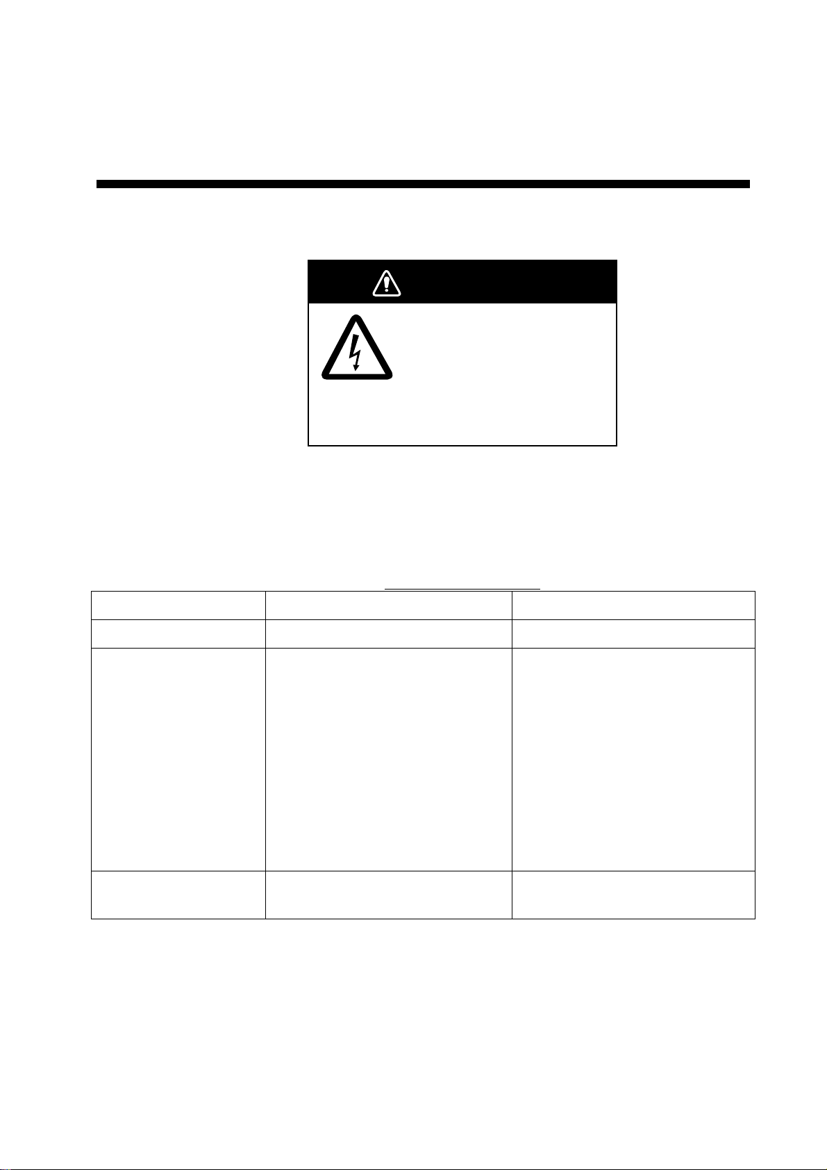
WARNING
Do not open the equipment.
Hazardous voltage which can
cause electrical shock exists
inside the equipment. Only
qualified personnel should
work inside the equipment.
6.1 Preventive Maintenance
Regular maintenance is important for optimum performance. A maintenance
schedule should be established and should at least include the items below.
Maintenance program
Item Check point Remedy
Control unit connector Check for tight connection. Tighten loosened connectors.
LCD The LCD will, in time, accumulate
a coating of dust which tends to
dim the picture.
Wipe the LCD carefully to prevent
scratching, using tissue paper
and an LCD cleaner. To remove
dirt or salt deposits, use an LCD
cleaner, wiping slowly with lens
paper so as to dissolve the dirt or
salt. Change paper frequently so
the salt or dirt will not scratch the
LCD. Do not use solvents such
as thinner, acetone or benzene
for cleaning.
Ground terminal Check for tight connection and
corrosion.
Clean or replace ground wire as
necessary.
6-1
Page 62
6. MAINTENANCE & TROUBLESHOOTING
6.2 Replacement of Fuse
The fuse in the processor unit protects the equipm ent from reverse polarity of
the ship’s mains and equipment fault. If the fuse blows, the power cannot be
turned on.
Contact your dealer about replacement of the fuse.
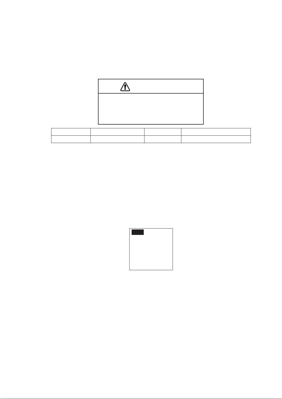
CAUTION
Use the proper fuse.
Use of a wrong fuse can cause fire or
damage the equipment.
Parts Name Type Code No. Remarks
Fuse FGMB 4A AC125V 000-119-976 Supplied as spare parts
6.3 Diagnostics
The NAVpilot-511/520/611 has a diagnostic function which checks the Processor
unit, Control unit, Heading sensor, Keyboard, LCD and Rudder for proper
operation.
To access a diagnostic function, do the following procedure:
1. Press the [TURN/MENU] key twice to show the menu.
2. Rotate the course control knob to select “TEST”.
3. Press the course control knob to show the test options window.
4. Rotate the course control knob to select an option.
5. Press the course control knob to start the diagnostic test.
6. Press the [MENU] key to finish.
OFF
PROCESSOR UNIT
CONTROL UNIT
HEADING SENSOR
KEYBOARD TEST
SCREEN TEST
RUDDER TEST
Test options window
6-2
Page 63

PROCESSOR UNIT TEST
PROCESSOR UNIT ID:2097151
ROM: OK 6454002-**.**
RAM: OK EEPROM: OK
RUDDER ANGLE OK 1
BYPASS/CLUTCH OK
REMOTECONT1 ON
REMOTECONT2 NOT USED
INPUT VOLTA GE 24.8 V
HEADING SENSOR: - PORT1/PORT2/RS232 - -/- -/- -
6.MAINTENANCE & TROUBLESHOOTING
**.**: Program version no.
CONTROL UNIT TEST
ROM: OK 6454003-**.**
RAM: OK EEPROM: OK
COMMUNICATION: OK
CONTROLLER ID: 255
CAN ID: XXXXXXX
PUSH MENU KEY TO RETURN.
CONTROL UNIT
**.**: Program version no.
Navpilot-520: 6454004-**.**
Navpilot-611: 6454005-**.**
HEADING SENSOR TEST
This test should be done while turning the connected sensor (PG-500) in a circle
at a rate of 60°/min. or more. If the sensor does not rotate, this test terminates
after one minute with NG result.
HEADING SENSOR
ROM: OK 6454101-**.**
RAM: OK EEPROM: OK
SENSOR: OK
RATE SENSOR: OK
TURN MORE THAN 180 IN 60
SECONDS.
PUSH MENU KEY TO RETURN.
**.**: Program vrsion no.
6-3
Page 64
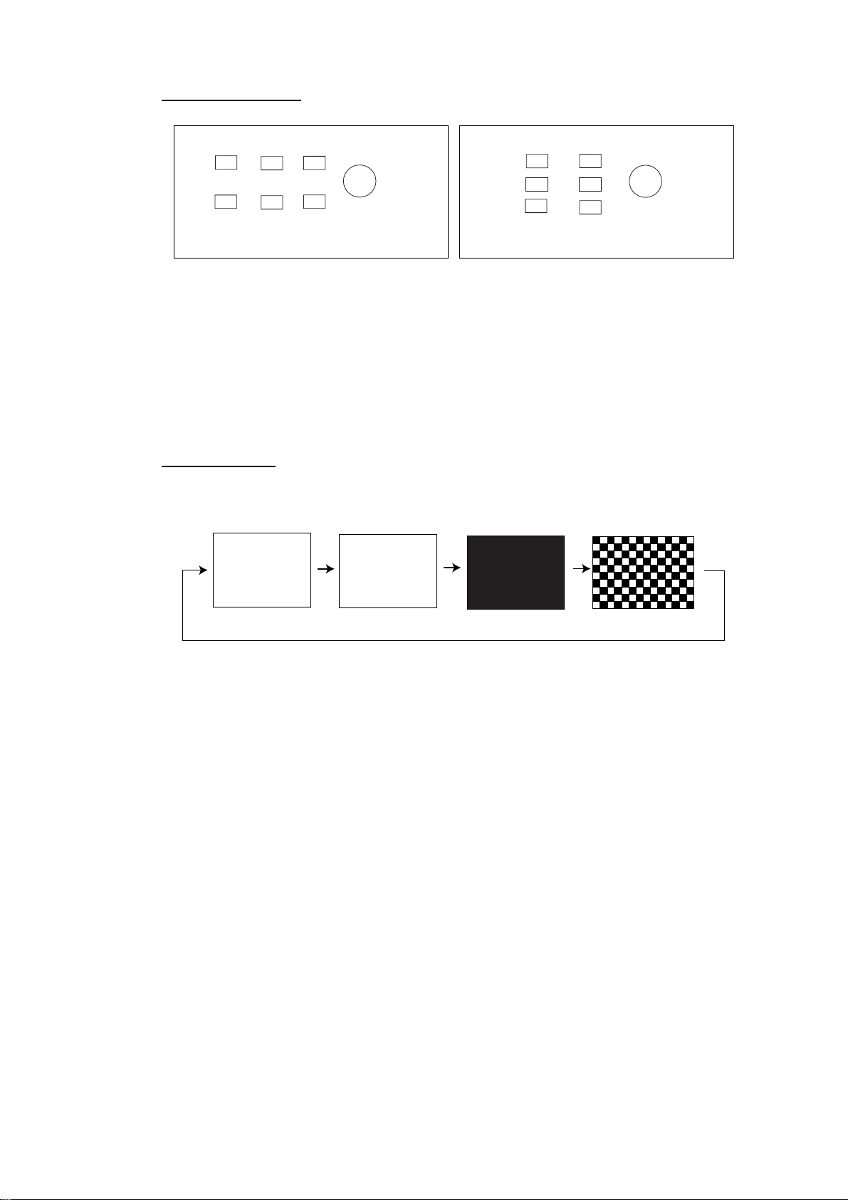
6. MAINTENANCE & TROUBLESHOOTING
KEYBOARD TEST
KEYBOARD TEST
001
PUSH MENU KEY THREE TIMES
TO RETURN.
KEYBOARD TEST
001
PUSH MENU KEY THREE TIMES
TO RETURN.
Navpilot-511/611 Navpilot-520
Operate each control on the control unit one by one. A key is functioning
properly if its on-screen location lights in black when the key is pressed. For the
course control knob, rotate it to show X-Y position; push it to confirm function.
To escape from the KEYBOARD TEST, press the [ TURN/MENU] key three
times.
SCREEN TEST
Each press of the course control knob changes the screen pattern in the
sequence shown below.
SCREEN TEST
CHANGE TEST PA TTERN?
YES ... PUSH ENTER KNOB.
PUSH MENU KEY TO RETURN.
To escape from the SCREEN TEST, press the [MENU] key.
(Flashing)
6-4
Page 65

6.MAINTENANCE & TROUBLESHOOTING
RUDDER SETUP AND AUTO TEST
The rudder test checks the following, and then shows the result of the check.
• Drive type
• The presence or absence of bypa ss/clutch circuit
• Rudder deadband
• Rudder speed
• Duty
This test should be executed when the boat does not run because of moving the
rudder.
When the rudder test is finished, a beep sounds and the message “RUDDER
TEST COMPLETED” and the results are show n.
RUDDER SETUP AND AUTO TEST
DRIVE TYPE: _ _ V
BYPASS/CLUTCH: _
DB : _ _. _ SPD: _ _._ /S
RUDDER DUTY: 50%
_ _
40 20 10 5
Rudder test
DRIVE TYPE: REVERSIBLE or SOLENOID
BYPASS/CLUTCH: EXIST or NON
DB: Shows the rudder deadband
SPD: Rudder speed
RUDDER DUTY: Rate of the rudder movement
5 10 20 40
6-5
Page 66

6. MAINTENANCE & TROUBLESHOOTING
SYSTEM DATA
You can confirm the current equipment and drive system status.
1. Press the [TURN/MENU] key twice to show the menu.
2. Rotate the course control knob to select “SYSTEM DATA”.
3. Press the course control knob to show the system data screen.
SYSTEM DATA
INPUT VOLTA GE: 24.4 V
CONTROLLER ID: 1
DRIVE TYPE: SOLENOID
BYPASS/CLUTCH: NON
FET TEMP.: 24.6 F
MOTOR DRIVE CUR.: 0.0 A
BYPASS/CLUTCH CUR.: 0.0 A
System data screen
6.4 Clearing Memories
Memories can be cleared to restore the Navpilot-511/520/611 to default settings.
For details, see the installation manual.
ID: 1
6-6
Page 67

6.MAINTENANCE & TROUBLESHOOTING
6.5 Error Messages
In addition to alarm messages your equipment displays error messages to alert
you of potential equipment trouble.
Error messages
Error message Meaning Remedy
Communication between the control
COMMUNICATION ERROR
A SUDDEN P OWER FAILURE
HAS OCCURRED.
RUDDER ANGLE ERROR
RUDDER DRIVE ERROR
DRIVE UNIT ERROR. PLEASE
TURN OFF AND CHECK DRIVE
CIRCUIT.
DRIVE UNIT IS OVERLOADED.
PLEASE TURN OFF AND
CHECK DRIVE CIRCUIT.
DRIVE UNIT IS OVERHEATED. 80°C temperature in drive unit was
BYPASS/CLUTCH IS
OVERLOADED.
DISCONNECT B/C
FU REMOTE CONTROLLER
ERROR
MISSING HEADING DATA
HEADING DATA ERROR
MISSING NAV DATA
DEGRADATION OF NAV DATA
QUALITY
PARAMETER ERROR OF NAV
MODE
unit and the processor unit is
interrupted for more than two
seconds.
Power supply was interrupted for
more than two seconds.
The rudder angle sent from the
rudder reference unit exceeded 55°.
The rudder did not move more than
3° over 10 seconds after rudder
command.
Current of more than 50 A was
detected on the drive circuit without
rudder command.
Overcurrent was detected. Check the drive circuit.
detected.
Current of more than 5 A was
detected on the bypass/clutch
circuit.
No current on the bypass/clutch
circuit.
Command from the FU remote
controller exceeded 55°.
The heading data from the heading
sensor is missing for 600 ms.
Heading data with error flag was
detected three times continuously.
The navigational data has been
interrupted for more than 15
seconds.
The navigation data was
incomplete.
The navigation data included an
error flag.
Check the interconnection
cable between control unit
and processor unit.
Press any key on the control
unit.
Check the rudder reference
unit, rudder angle and its
connection.
Check the hydraulic system.
After the solving problem, do
the rudder test.
Check the drive circuit.
Check the drive unit system.
Check the bypass/clutch
circuit.
Check the remote controller
connection.
Check the heading sensor
and interconnection cable..
Check the heading sensor.
Check the navigator.
Check the navigator settings.
Continued on next page.
6-7
Page 68

6. MAINTENANCE & TROUBLESHOOTING
Error messages (con’t)
INPUT VOLTAGE IS OVER
(UNDER) LIMIT
MAGNETIC SENSOR ERROR
RATE SENSOR ERROR
NO CALIBRATION Calibration not yet executed.
The input power source fluctuated
beyond tolerance.
The heading data from the heading
sensor was wrong.
Check ship’s mains.
Check the heading sensor.
Ask your dealer to do the
calibration.
6-8
Page 69
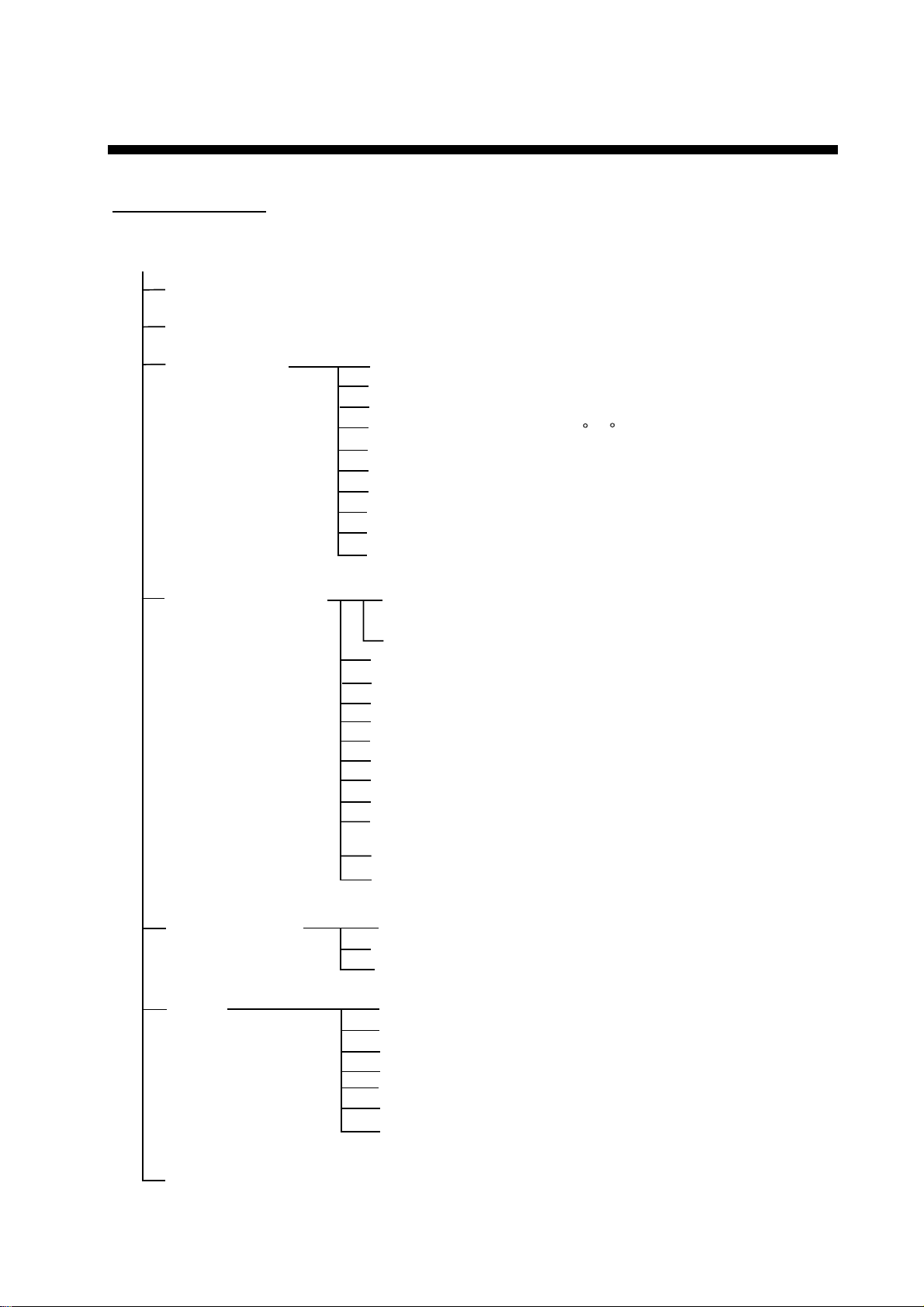
MENU TREE
STBY mode menu
[MENU] key
MESSAGE (Shows error messages.)
CONTRAST/BRILLIANCE (Contrast: 1 to 16,10, Brill: 1 to 8, 8)
ALARM SETUP
PARAMETER SETUP
AUDIO (
ALARM INTERVAL (
WATCH ALARM (OFF, ON)
DEVIATION ALARM (1 to 90 ,
XTE (
SPD (
DPT (
TMP (
TRIP LOG ALARM (
CLEAR TRIP LOG (
SEA STATE (
DEVIATION LEVEL* (
MANUAL PARAMETERS
AUT O TRIM (OFF,
ADVANCED AUTO (
AUT O NET TO WING (
NAV MODE (
NAV SRC (
RADIUS OF ORBIT (0.05 to 9.99 nm,
SPIRAL SPEED (0.1 to 8.0 kt,
FISH MODE (
WAYPOINT SWITCHING (
SPD CALC. (
INTERNAL BUZZER
SHORT
OFF
, ON)
OFF
, UNDER, OVER, INSIDE, OUT)
OFF
, SHALL, DEEP, INSIDE, OUT)
OFF
, UNDER, OVER, INSIDE, OUT, CUR.)
OFF
, ON)
NO
, YES)
FULL-AUTO,
MANUAL-MODERATE, MANUAL ROUGH)
, INTERNAL +EXTERNAL)
, LONG, CONTINUE)
30
)
SEMI-AUTO, MANUAL-CALM,
AUTO
, LEVEL)
ON
, 1-100,
OFF
, ON)
OFF
, ON)
XTE
, COURSE)
PORT 1
, PORT 2, BOTH)
1.0 kt
OFF
, ORBIT TO STBD,
ORBIT TO PORT, FIGURE EIGHT)
AUTO
, MANUAL)
SOG
, STW, MANUAL)
40
)
0.10 nm
)
)
SYSTEM SETUP
TEST
SYSTEM DATA
KEY BEEP (
LOCK (LOCK,
PANEL DIMMER (1 to 8,
OFF
PROCESSOR UNIT
CONTROL UNIT
HEADING SENSOR
KEYBOARD TEST
SCREEN TEST
RUDDER TEST
*: Available only when FULL-AUTO is selected at SEA STATE.
ON
, OFF)
UNLOCK
8
)
)
MN-1
Page 70

MENU TREE
AUTO mode menu
[MENU] key
MESSAGE (Shows error messages.)
CONTRAST/BRILLIANCE (Contrast: 1 to 16, 10, Brill: 1 to 8, 8)
ALARM SETUP See page MN-1.
ADVANCED AUTO (
OFF
, ON)
NAV mode menu
SEA STATE (
DEVIATION LEVEL* (
MANUAL PARAMETERS** (WHEATHER; 1 to 10 ,
AUT O TRIM (OFF,
AUTO NET TOWING (
SPD CALC. (
RADIUS OF ORBIT (0.05 to 9.99 nm,
SPIRAL SPEED (0.1 to 8.0 kt,
SYSTEM DATA
[MENU] key
MESSAGE (Shows error messages.)
CONTRAST/BRILLIANCE (Contrast: 1 to 16,
ALARM SETUP See page MN-1.
NAV SRC (
SEA STATE (
DEVIATION LEVEL* (
MANUAL PARAMETERS** (WHEATHER; 1 to 10 ,
AUT O TRIM (OFF,
WAYPOINT SWITCHING (
NAV MODE (
FISH MODE (
SPD CALC. (
RADIUS OF ORBIT (0.05 to 9.99 nm,
SPIRAL SPEED (0.1 to 8.0 kt,
SYSTEM DATA
FULL-AUTO,
MANUAL-MODERATE, MANUAL ROUGH)
*: Available only when FULL-AUTO is selected at SEA STATE.
**: Default settings are depends on ship's length and width entered on installing.
PORT 1
FULL-AUTO,
MANUAL-MODERATE, MANUAL ROUGH)
RUDDER GAIN; 0.1 to 2.0,
COUNT RUDDER; 0.1 to 4.0)
ORBIT TO PORT, FIGURE EIGHT)
*: Available only when FULL-AUTO is selected at SEA STATE.
**: Default settings are depends on ship's length and width entered on installing.
SEMI-AUTO, MANUAL-CALM,
AUTO
, LEVEL)
RUDDER GAIN; 0.1 to 2.0,
COUNT RUDDER; 0.1 to 4.0)
ON
, 1-100, 40)
OFF
, ON)
SOG
, STW, MANUAL)
0.10 nm
1.0 kt
10
, Brill: 1 to 8, 8)
, PORT 2, BOTH)
SEMI-AUTO, MANUAL-CALM,
AUTO
, LEVEL)
ON
, 1-100, 40)
AUTO
, MANUAL)
XTE
, COURSE)
OFF
, ORBIT TO STBD,
SOG
, STW, MANUAL)
0.10 nm
1.0 kt
)
)
)
)
MN-2
Page 71

FURUNO
NAVpilot-511/520/611
SPECIFICATIONS OF AUTOPILOT
NAVpilot-511/520/611
1 CONTROL UNIT
1.1 Display Monochrome LCD, 85.2 (W) x 43. 6 (H) mm, 160 x 80 dots
1.2 Backlight Adjusta ble in 8 steps
1.3 Contrast 16 steps
1.4 Useable set 6 sets
2 PROCESSOR UNIT
2.1 Rudder mode STBY, Auto, Dodge, Remote, Advanced Auto*, N avigation*
2.2 Weather mode FULL-AUTO/ SEMI-AUTO/
MANUAL-CALM/ MANUAL-MODERATE/ MANUAL-ROUGH
2.3 Rudder angle ratio AUTO/0.1-2.0
2.4 Rudder angle equiv alent AUTO/0.1-4.0
2.5 Rudder angle settings 45° max.
2.6 Weather adjustment 1° to 10°
2.7 Alarm Heading deviation, Cross-track error*, Ship’s s peed*, Depth*,
Water temperature*, Log trip, Watch
*: Navigation data required
3 INTERFACE
3.1 Ports Navigation data in/out (NMEA): 1, Output (NMEA): 1
Input (NMEA): 1, I/O for Heading Sensor (NMEA): 1
3.2 Input sentences NMEA 0183, Ver-1.5/2.0/ 3. 0
Command bearing APA, APB, BOD/X TE, RMB
Ship’s location (L/L) GGA, RMC, RMA, GLL, GNS
Ship’s location (LOP) GLC, GTD, RMA
SOG/COG VTG, RMC, RMA
STW VHW
Heading (HDG) HDT, HDG, HDM
Destination RMB, WPL
Bearing/ Distance RMB, BWC, BWR
Time RMC, ZDA
Arrival alarm AAM, RM B
Cross track error APB, XTE, RMB
Water depth DPT, DBT
Water temperature MTW
Wind speed/bearing VPW, MWD, MWV
3.3 Output sentences NMEA 0183, Ver-1.5/2.0/3.0
AAM, ALR, ASD, BWC, BWR, DBT, DPT, GGA, GLC, GLL, GTD,
GNS, HDG, HDT, HSC, MTW, MWV, RMA, RMB, RMC, RSA, VBW,
VHW, VTG, WPL, XTE, ZDA
SP - 1 E7250S01A-M
080805
Page 72

FURUNO
3.4 I/O control RS-232C (NMEA)
5 POWER SUPPLY
3.1 Processor unit 12-24 VDC: 3-2 A (Control Unit: 6 sets)
6 ENVIRONMENTAL CONDITIONS
4.1 Ambient temperature -15°C to +55°C
4.2 Relative humid ity 95% at 40°C
6.3 Degree of protection
Processor unit: IPX2
Remote controller/ Rudder reference unit: IPX5
Control unit IPX 5 (Navpilot-511/611), IPX6 (Navpilot-520)
6.4 Vibration IEC 60945
7 UNIT COLOR
5.1 Processor unit N3.0
5.2 Control unit N3.0 (Navpilot-511/520), N2.5 (Navpi lot - 611)
5.3 Remote controller N3.0 (FAP-5552/6232), N1.5 (FAP-6212/6222)
5.4 Rudder reference unit N1.0
5.5 Junction box N3.0
NAVpilot-511/520/611
SP - 2 E7250S01A-M
080805
Page 73

INDEX
A
ADDVANCED AUTO mode .....................3-3
ALARM INTERV AL..................................5-2
AUDIO ALARM........................................5-2
AUTO mode.............................................3-2
AUTO TRIM.............................................4-7
ANALOG INDICATO R BAR.....................2-6
B
Brilliance..................................................2-3
C
Contrast...................................................2-3
COUNTER RUDDER ..............................4-6
Course control knob ................................2-1
D
Deviation alarm........................................5-3
Distance alarm.........................................5-7
DODGE mode .......................................3-20
F
FIGURE EIGHT............................. 3-7, 3-14
K
KEY BEEP.............................................4-10
L
LOCK.....................................................4-11
N
NAV mode................................................3-4
NET TOWING..........................................4-8
Normal Display ........................................2-4
O
ORBIT................................................... 3-10
P
PANEL DIMMER................................... 4-12
Parameter................................................4-2
R
REMOTE mode .................................... 3-16
RUDDER GAIN........................................4-5
S
Sailing method.........................................3-5
SEA STATE..............................................4-2
Speed alarm.............................................5-5
STBY mode .............................................3-1
T
Temperature alarm ..................................5-7
Tests.........................................................6-2
TLL........................................................ 3-15
W
Waypoint...................................3-5, 3-6, 3-7
WA TCH ALARM.......................................5-3
WEATHER...............................................4-6
X
XTE alarm................................................5-4
IN-1
 Loading...