

Page 1
Page 2

IMPORTANT NOTICE
• No part of this manual may be copied or reproduced without written permission.
• If this manual is lost or worn, contact your dealer about replacement.
• The contents of this manual and equipment specifications are subject to change without notice.
• The example screens (or illustrations) shown in this manual may not match the screens you see
on your display. The screen you see depends on your system configuration and equipment set-
tings.
• This manual is intended for use by native speakers of English.
• FURUNO will assume no responsibility for the damage caused by improper use or modification
of the equipment or claims of loss of profit by a third party.
• Please carefully read and follow the operation, installation and maintenance procedures set
forth in this manual.
• Store this manual in a convenient place for further reference.
i
Page 3
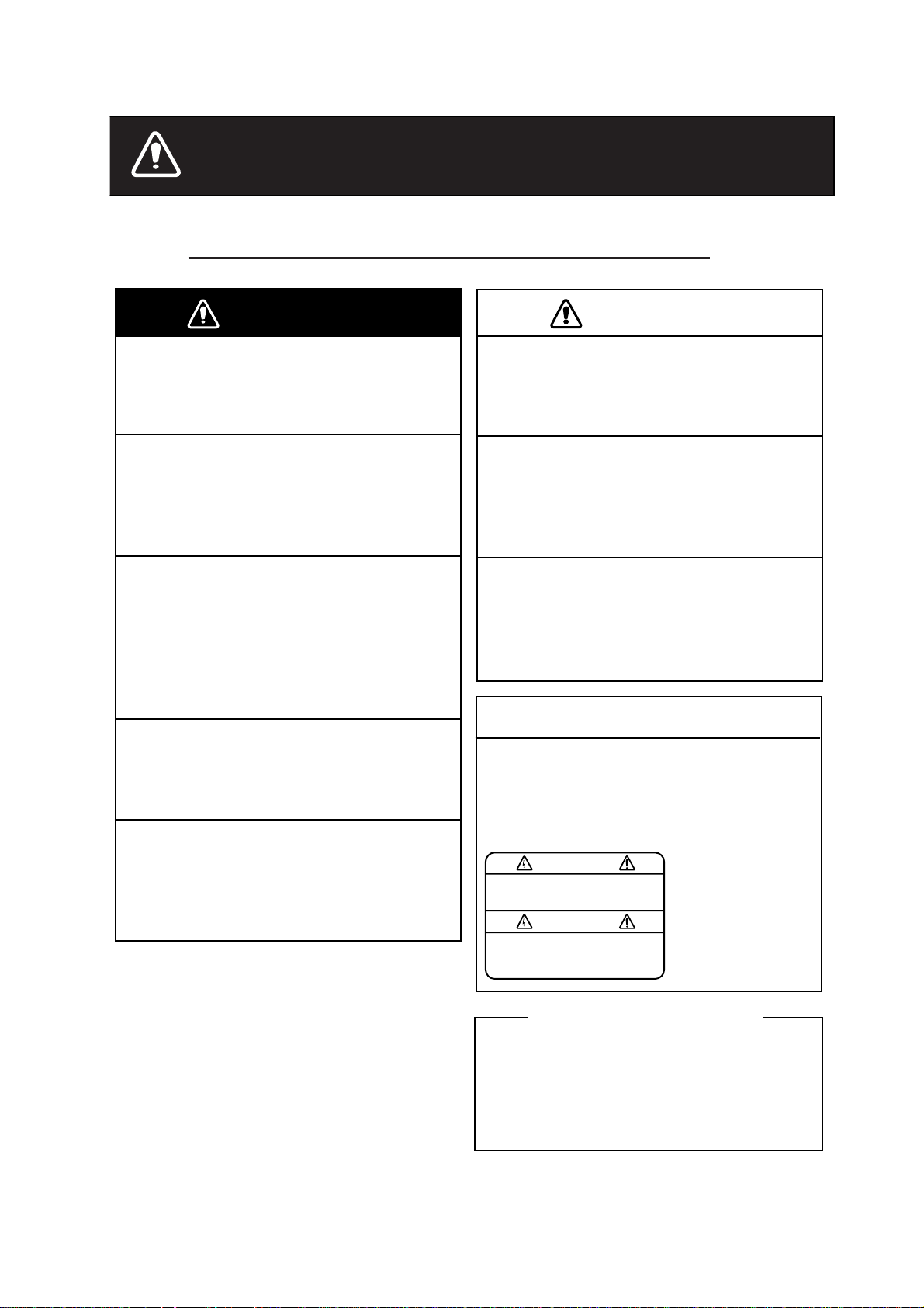
SAFETY INSTRUCTIONS
Safety Instructions for the Operator
WARNING
Do not open the equipment.
There are no user-serviceable parts
inside.
Do not disassemble or modify the
equipment.
Fire, electrical shock or serious injury
can result.
Immediately turn off the power at the
switchboard if the equipment is
emitting smoke or fire.
Continued use of the equipment can
cause fire or electrical shock. Contact a
FURUNO agent for service.
Do not maneuver the vessel based
on the depth indication alone.
Grounding may result.
Use the proper fuse.
Fuse rating is shown on the equipment.
Use of a wrong fuse can result in
damage to the equipment.
CAUTION
Do no turn on the equipment with the
transducer out of water.
The transducer may be damaged.
The picture is not refreshed when
picture advancement is stopped.
Maneuvering the vessel in this condition
may result in a dangerous situation.
Use the proper gain setting.
Incorrect gain may produce wrong depth
indication, possibly resulting in a
dangerous situation.
NOTICE
A warning label is attached to the
equipment. Do not remove the label.
If the label is missing or damaged,
contact a FURUNO agent or dealer
about replacement.
WARNING
To avoid electrical shock, do not
remove cover. No user-serviceable
parts inside.
Name:
Warning Label (1)
Type: 86-003-1011-1
Code No.: 100-236-231
About the TFT LCD
The TFT LCD is constructed using the
latest LCD techniques, and displays
99.99% of its pixels. The remaining 0.01%
of the pixels may drop out or blink, however
this is not an indication of malfunction.
ii
Page 4
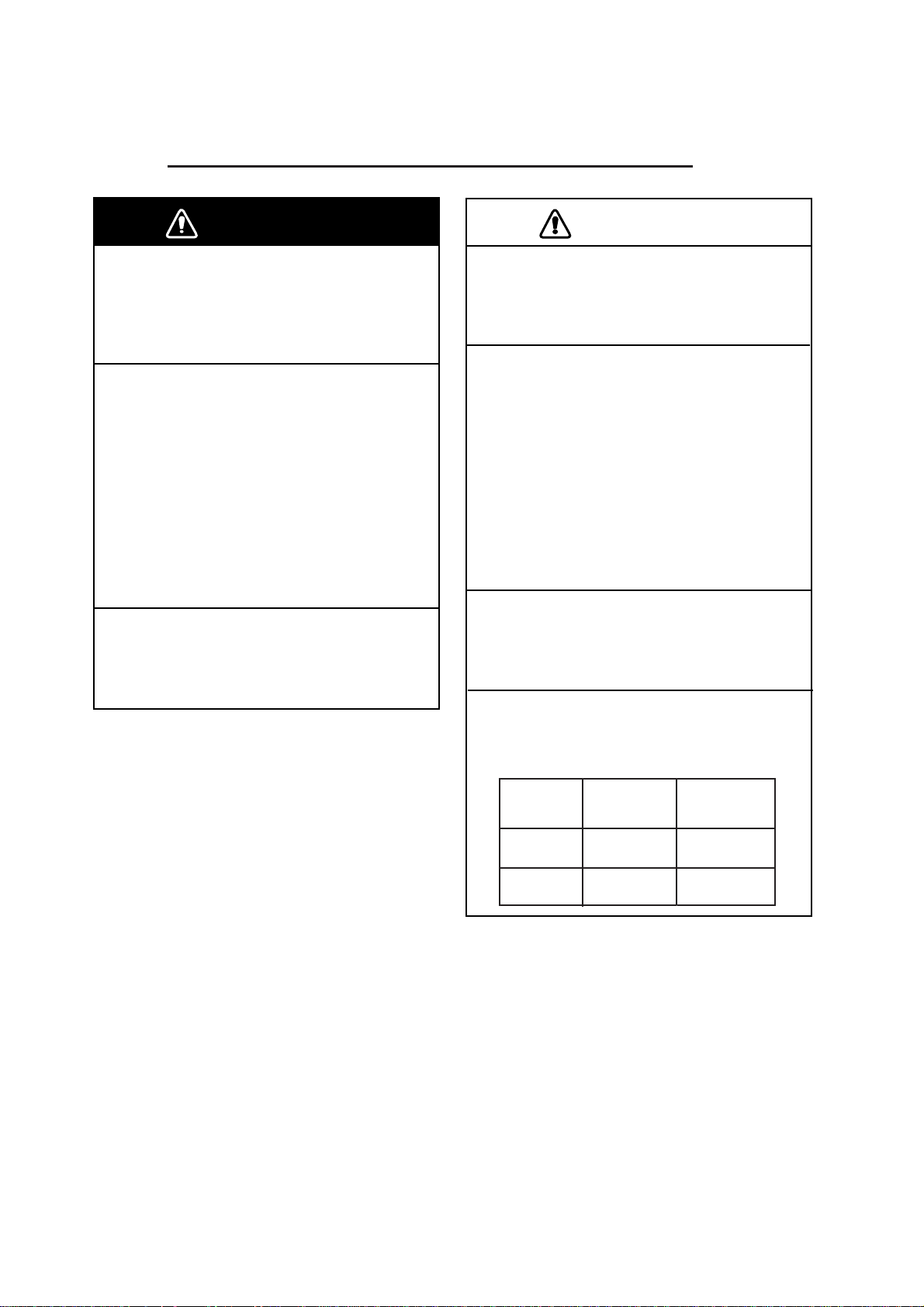
SAFETY INSTRUCTIONS
Safety Instructions for the Installer
WARNING
Turn off the power at the switchboard
before beginning the installation.
Fire or electrical shock can result if the
power is left on.
Be sure no water leaks in at the transducer or sensor mounting location.
Water leakage can sink the vessel. Also
confirm that the transducer and sensor
will not loosen by ship's vibration. The
installer of the equipment is solely
responsible for the proper installation of
the equipment. FURUNO will assume no
responsibility for any damage associated
with improper installation.
Use the specified power cable.
Use of other power cable may result in
fire.
CAUTION
Do not install the equipment where
air bubbles and noise are present.
Performance will be affected.
The following are guidelines for
handling of the transducer cable.
- Keep fuels and oils away from the
cable.
- Locate it in a safe place.
- Do no paint the cable.
The sheath of the cable is made of
chloroprene rubber (or polychloride vinyl).
For this reason do not paint the cable.
Do not turn on the equipment with the
transducer out of water.
The transducer may be damaged.
Observe the following compass safe
distances to prevent interference to a
magnetic compass:
Display
unit
FCV-620
FCV-585
Standard Steering
compass compass
0.3 m 0.3 m
0.5 m 0.3 m
iii
Page 5

TABLE OF CONTENTS
FOREWORD ............................... v
SYSTEM CONFIGURATION ..... vi
EQUIPMENT LISTS.................. vii
1. OPERATION ........................... 1
1.1 Control Description......................... 1
1.2 Power On/Off ................................. 2
1.3 Adjusting Display Contrast and
Brilliance......................................... 2
1.4 Choosing a Display Mode .............. 2
1.5 Choosing Range ............................ 5
1.6 Adjusting Gain................................ 5
1.7 Measuring Depth............................ 6
1.8 Menu Operating Procedure............ 6
1.9 Shifting Range................................ 7
1.10Choosing Picture Advance Speed
....................................................... 7
1.11 Suppressing Interference ............... 8
1.12 Suppressing Low Level Noise........ 9
1.13 Erasing Weak Echoes.................... 9
1.14 A-Scope Display........................... 10
1.15 Fish Information ........................... 10
1.16 Alarms .......................................... 11
1.17 FUNC Key .................................... 13
1.18 Waypoints .................................... 13
1.19 Setting Up Nav Data Displays...... 15
1.20 Menu Items .................................. 16
4. INSTALLATION ....................25
4.1 Display Unit.................................. 25
4.2 Thru-hull Mount Transducer......... 26
4.3 Transom Mount Transducer......... 28
4.4 Inside-hull Transducer ................. 28
4.5 Triducer........................................ 30
4.6 Optional Water Temperature/Speed
Sensor.......................................... 33
4.7 Optional Water Temperature
Sensor.......................................... 33
4.8 Wiring........................................... 34
4.9 IEC 61162-1 Data Sentences ...... 36
4.10Adjustments after Installation....... 37
MENU TREE ............................. 38
SPECIFICATIONS ................ SP-1
OUTLINE DRAWINGS............ D-1
INTERCONNECTION
DIAGRAM ............................... S-1
Declaration of Conformity
2. SYSTEM MENU .................... 20
2.1 Displaying System Sub Menu ...... 20
2.2 Range Menu................................. 20
2.3 Key Menu ..................................... 20
2.4 Lang Menu ................................... 20
2.5 Units Menu................................... 21
2.6 Calib Menu................................... 21
2.7 Demo Menu.................................. 21
3. MAINTENANCE, TROUBLE-
SHOOTING ........................... 22
3.1 Maintenance................................. 22
3.2 Cleaning the Display Unit............. 22
3.3 Transducer Maintenance ............. 22
3.4 Replacing the Fuse ...................... 22
3.5 Battery Voltage Alert .................... 22
3.6 Troubleshooting ........................... 23
3.7 Diagnostics................................... 23
3.8 Test Pattern.................................. 24
3.9 Memory Clear............................... 24
iv
Page 6

FOREWORD
A Word to FCV-620/585
Owners
Congratulations on your choice of the
FURUNO FCV-620/585 Color LCD Sounder.
We are confident you will see why the
FURUNO name has become synonymous
with quality and reliability.
For over 50 years FURUNO Electric Company has enjoyed an enviable reputation for
innovative and dependable marine electronics equipment. This dedication to excellence is furthered by our extensive global
network of agents and dealers.
This equipment is designed and constructed
to meet the rigorous demands of the marine
environment. However, no machine can perform its intended function unless operated
and maintained properly. Please carefully
read and follow the recommended procedures for operation and maintenance.
We would appreciate hearing from you, the
end user, about whether we are achieving our
purposes.
Thank you for considering and purchasing
FURUNO equipment.
Features
The FURUNO FCV-620/585 is a dual
frequency (50 kHz and 200 kHz) Color LCD
Sounder. Comprised of a display unit and a
transducer, the FCV-620 displays underwater
conditions on a 5.6-inch color LCD and the
FCV-585 on an 8.4-inch color LCD.
The main features of the FCV-620/585 are
• Bright color LCD gives excellent readability
even in broad daylight.
• Waterproof construction permits installation
on open bridge.
• Automatic function being available on
detecting fish school and bottom at both
shallow and deep depth permits best display.
• User-programmable nav data displays provide analog and digital nav data.
• Alarms: Bottom, Fish (bottom lock and
normal), Speed, Water Temperature and
Arrival. (Speed, arrival and water temperature alarms require appropriate sensor.)
• White line feature helps discriminate fish
lying near the bottom.
• Destination waypoint feature provides
range, bearing, and time-to-go to destination waypoint (up to 20 waypoints).
v
Page 7
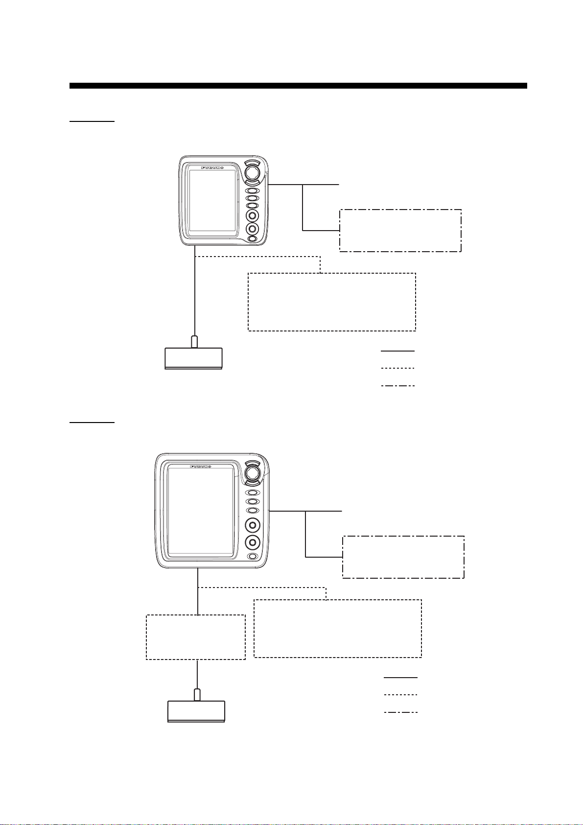
SYSTEM CONFIGURATION
DISPLAY UNIT
ly
5
FCV-620
CV-620
Power supply
12-24 VDC
GPS Navigator
or
Water temperature sensor
Water temperature/speed sensor
ST-02MSB, ST-02PSB
Water temperature sensor
T-02MSB, T-02MTB, T-03MSB
20-5PSD, 520-5MSD, 525-5PWD,
FCV-585
Transducer
525ST-MSD, 525ST-PWD
DISPLAY UNIT
CV-585
Matching Box
MB-1100*
: Standard
: Option
: Local Supp
Power supply
12-24 VDC
GPS Navigator
or
Water temperature sensor
Water temperature/speed sensor
ST-02MSB, ST-02PSB
Water temperature sensor
T-02MSB, T-02MTB, T-03MSB
: Standard
: Option
Transducer
520-5PSD, 520-5MSD, 525-5PWD,
525ST-MSD, 525ST-PWD
*: For connection to 1 kW transducer
(50B-6, 50B-6B, 200B-5S, 50/200-1T)
: Local Supply
vi
Page 8
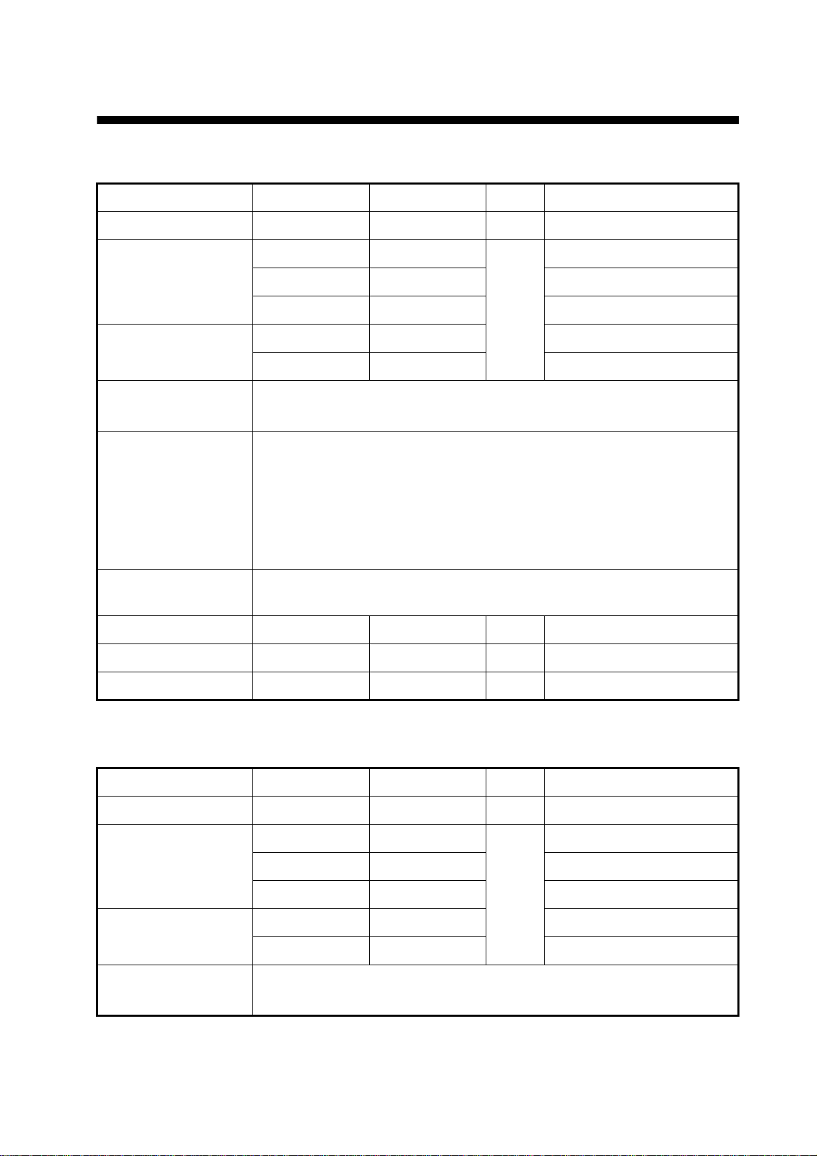
EQUIPMENT LISTS
Standard supply for FCV-620
Name Type Code No. Qty Remarks
Display Unit CV-620 - 1 With hard cover
520-5PSD 000-015-204
Transducer
Triducer (transducer
plus spd/temp sensor)
Installation Materials
(CP02-07900)
Accessories
(FP02-05501)
Spare Parts
(SP02-05001)
Template C22-00502 000-156-349 1 For flush mounting
520-5MSD 000-015-212 Thru-hull mount
525-5PWD 000-146-966 Transom mount
525ST-MSD 000-015-263 Thru-hull mount
525ST-PWD 000-015-261 Transom mount
• Cable assy. (1 pc., KON-004-02M, 000-156-405, for power and data)
• Self-tapping screw (4 pcs., 5x25 SUS304, 000-802-082)
• Flush mounting sponge (1 pc., 02-154-1601-0, 100-329-460)
• Wing nut (4 pcs., M4 SUS304, 000-863-331)
• Flat washer (4 pcs., M4 SUS304, 000-864-126)
• Spring washer (4 pcs., M4 SUS304, 000-864-256)
• Threaded rod (4 pcs., M4x50 SUS304, 000-147-539)
• MJ cable cap (1 pc., 02-154-1221-1, 100-329-441)
Fuse (2 pcs., FGBO-A 125V 2A, 000-155-849-10)
Thru-hull mount
1
Operator’s Guide MLG-23740 000-156-373 1
Operator’s Manual OME-23740 000-156-346 1
Standard supply for FCV-585
Name Type Code No. Qty Remarks
Display Unit CV-585 - 1 With hard cover
Transducer
Triducer (transducer
plus spd/temp sensor)
Installation Materials
(CP02-07900)
520-5PSD 000-015-204
520-5MSD 000-015-212 Thru-hull mount
525-5PWD 000-146-966 Transom mount
525ST-MSD 000-015-263 Thru-hull mount
525ST-PWD 000-015-261 Transom mount
• Cable assy. (1 pc., KON-004-02M, 000-156-405, for power and data)
• Self-tapping screw (4 pcs., 5x25 SUS304, 000-802-082)
Thru-hull mount
1
vii
Page 9
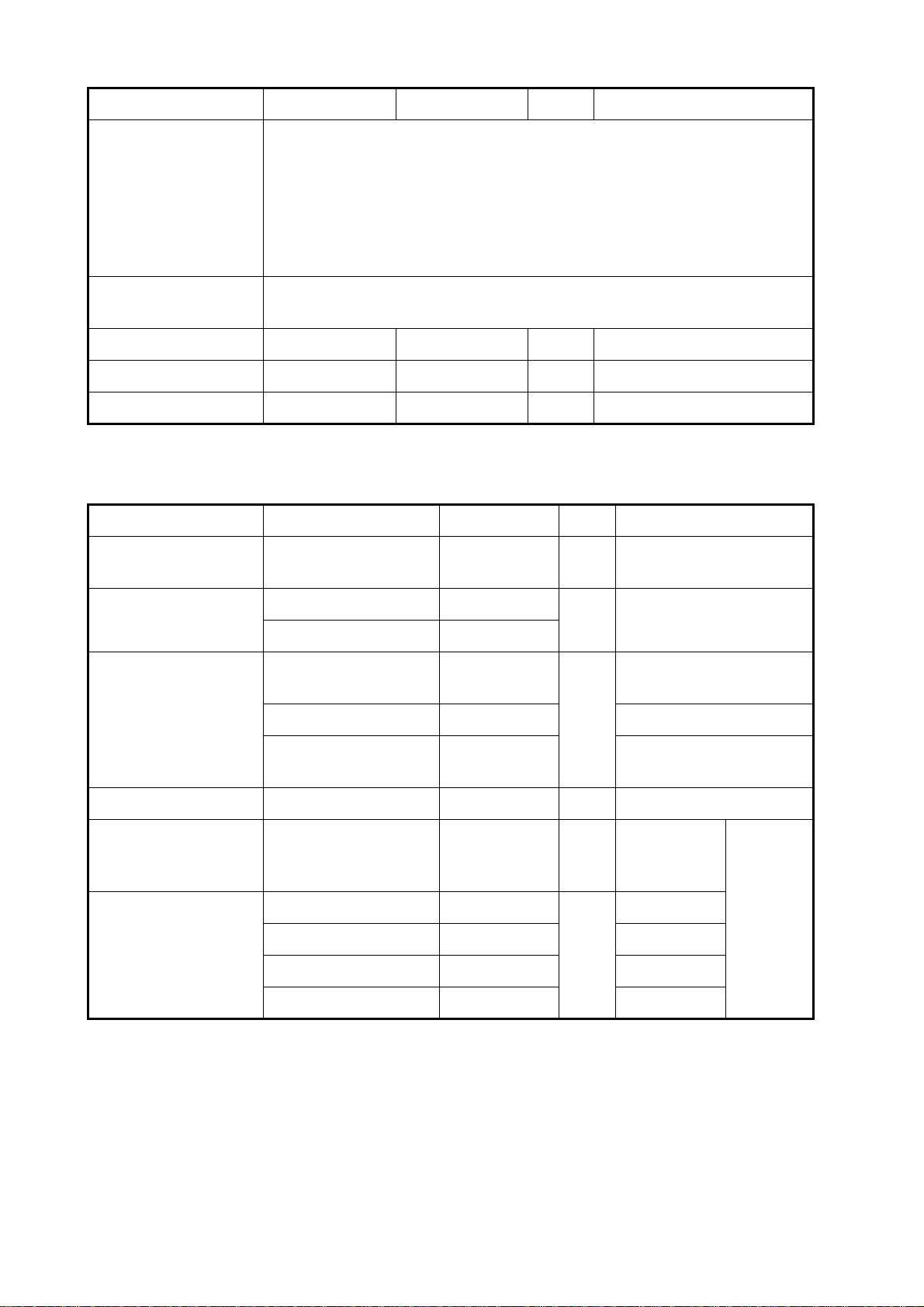
EQUIPMENT LISTS
Name Type Code No. Qty Remarks
Accessories
(FP02-05601)
• Flush mounting sponge (1 pc., 02-155-1081-1, 100-330-851-10)
• Wing nut (4 pcs., M4 SUS304, 000-863-331)
• Flat washer (4 pcs., M4 SUS304, 000-864-126)
• Spring washer (4 pcs., M4 SUS304, 000-864-256)
• Threaded rod (4 pcs., M4x50 SUS304, 000-147-539)
• MJ cable cap (1 pc., 02-154-1221-1, 100-329-441)
Spare Parts
(SP02-05001)
Template C22-00504 000-158-577 1 For flush mounting
Operator’s Guide MLG-23740 000-156-373 1
Operator’s Manual OME-23740 000-156-346 1
Fuse (2 pcs., FGBO-A 125V 2A, 000-155-849-10)
Optional equipment for FCV-620/585
Name Type Code No. Qty Remarks
Conversion Cable 02S4147 000-141-082 1
Water Temperature &
Speed Sensor
Water Temperature
ST-02MSB 000-137-986
ST-02PSB 000-137-987
T-02MTB 000-040-026
T-02MSB 000-040-040 Thru-hull mount
For water temperature
and spd/temp sensors
1 Thru-hull type
Transom mount, w/8 m
cable
1
T-03MSB 000-040-027
Inner Hull Kit S 22S0191 000-802-598 1
Matching Box MB-1100 000-041-353 1
50B-6 000-015-042
50B-6B 000-015-043 15 m, 1 kW
Transducer
200B-5S 000-015-029 10 m, 1 kW
50/200-1T 000-015-170 10 m, 1 kW
Thru-hull mount, w/8 m
cable
For connection to 1 kW
transducer
10 m, 1 kW
1
For FCV585
viii
Page 10
1. OPERATION
FCV - 620
1
2
3
4
5
6
7
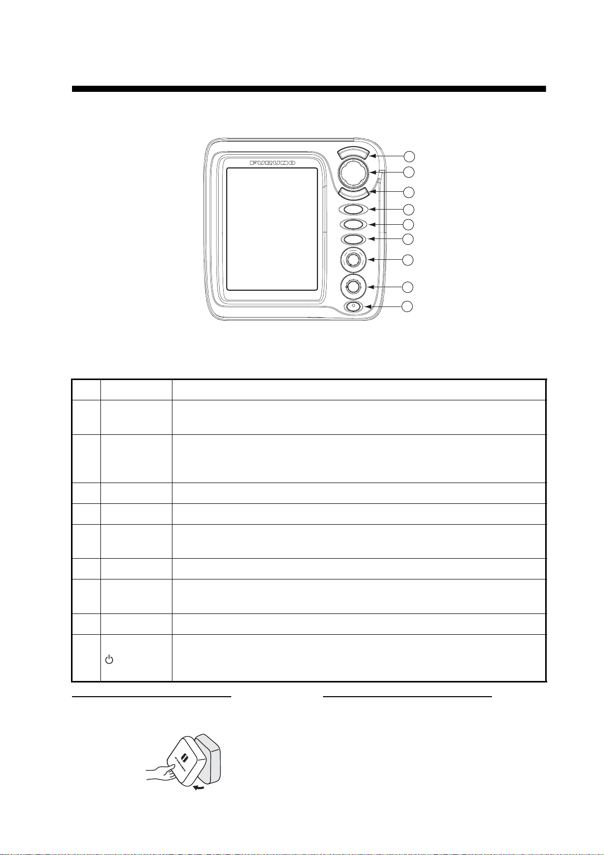
1.1 Control Description
U
/
E
N
S
E
C
M
E
R
N
E
T
RANGE
MARK
FUNC
6
4
2
8
AUTO
0
10
G
A
N
I
A
U
L
D
H
F
F
L
Z
O
M
O
O
M
O
Z
N
1
A
V
V
A
2
N
M
E
O
D
B
L
R
I
L
Display unit for FCV-620
Note: The FCV-620 and FCV-585 share the same features. For sake of brevity, this manual uses
“FCV-620”.
8
9
No. Control Function
1 MENU/ESC
STWX
2
(TrackPad)
• Opens/closes menu.
• Escapes from current operation.
• Moves cursor on the menu.
• Adjusts settings.
• Moves VRM (Variable Range Marker) by using S or T except for nav mode.
3 ENTER Saves settings.
4 RANGE Opens display range setting window.
5MARK
Records the position of an important echo as waypoint. (Outputs latitude and
longitude position to a plotter.)
6 FUNC Opens user defined window.
7GAIN
• Push: Opens automatic gain setting window.
• Rotating: Manually adjusts gain (with automatic gain adjustment off).
8 MODE Selects display mode.
• Turns power on/off.
9
/BRILL
• Opens display contrast/brilliance setting window. (The FCV-585 does not
have the contrast function.)
How to remove the hard cover
Place fingers below cover, pull cover forward
and lift it.
When removing the display unit
To keep out dust from connectors:
- Cover transducer cable’s connector with MJ
cable cap (supplied).
- Cover two connectors on display unit with their
caps.
- Cover power cable’s connector with its cap.
1
Page 11
1. OPERATION
1.2 Power On/Off
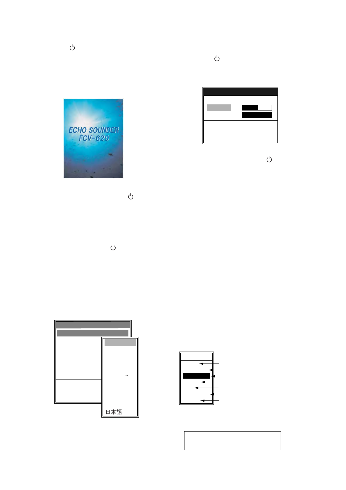
1. Press the /BRILL key to turn on the
power.
The unit beeps, the startup screen appears,
and then the equipment checks the ROM
and RAM for proper operation. After the completion of the equipment check, the last-used
display appears.
Startup screen
2. To turn off the power, press the /BRILL
key more than three seconds.
The time remaining until power is turned off
is counted down on the screen.
Note1: If "ROM/RAM check error!" appears, try
to press any key except the /BRILL key to
start operation. However, the equipment may
not work properly. Contact your dealer.
Note2: The first time you turn on the power (or
any time the power is applied after a memory
reset), the installation menu appears. See the
figure below.
When this occurs, press the MENU/ESC key
twice to close the menu.
Installation
Language : English
Depth
Temp
Speed
Wind
Distance Unit
Demonstrate
S/T : Select
[ENTER] : Enter
[MENU]
Unit
Unit
Unit
Unit
: Quit
English
Francais
Espanol
Deutsch
Italiano
Portugues
Dansk
Svenska
Norsk
Suomi
Installation menu
,
∼
1.3 Adjusting Display Contrast and Brilliance
1. Press the /BRILL key momentarily to
show the contrast/brilliance adjustment window. (The FCV-585 does not have the contrast function.)
Contrast/Brill
W Min Max X
Contrast 5
Brill 9
S/T : Select
[ENTER] : Set
[MENU] : Cancel
Contrast/brilliance adjustment window
2. To adjust brilliance, press the /BRILL key.
Continual pressing changes the brilliance
continuously (0
1→...). “0” is the dimmest and “9” is the
brightest.
After selecting “Brill” by using
may also use
3. To adjust contrast, after selecting “Contrast"
by using
620). “0” is the lowest and “9” is the highest.
4. Press the ENTER key to save the setting and
close the window.
Note: When the power is reapplied after turning
off the equipment with minimum brilliance, minimum brilliance will be set after the equipment
goes through its initial start up. (The start up
screen appears with the maximum brilliance.)
Adjust the brilliance as necessary.
→1→...→9→8→...→0→
S or T, you
W or X to adjust brilliance.
S or T, use W or X (only for FCV-
1.4 Choosing a Display Mode
1. Rotate the MODE knob to open the mode
setting window, which is displayed for five
seconds.
MODE
NAV1
LF-ZOOM
LF
DUAL
HF
HF-ZOOM
NAV2
*: The indication at the top on the screen is
B/L-LF, B/Z-LF or M/Z-LF.
**: The indication at the top on the screen is
B/L-HF, B/Z-HF or M/Z-HF.
B/L: Bottom lock, LF: Low frequency,
B/Z: Bottom zoom, HF: High frequency,
M/Z: Marker zoom
Nav data mode 1
Low frequency zoom mode*
Low frequency mode (50 k)
Dual frequency mode
High frequency mode (200 k)
High frequency zoom mode**
Nav data mode 2
2
Page 12
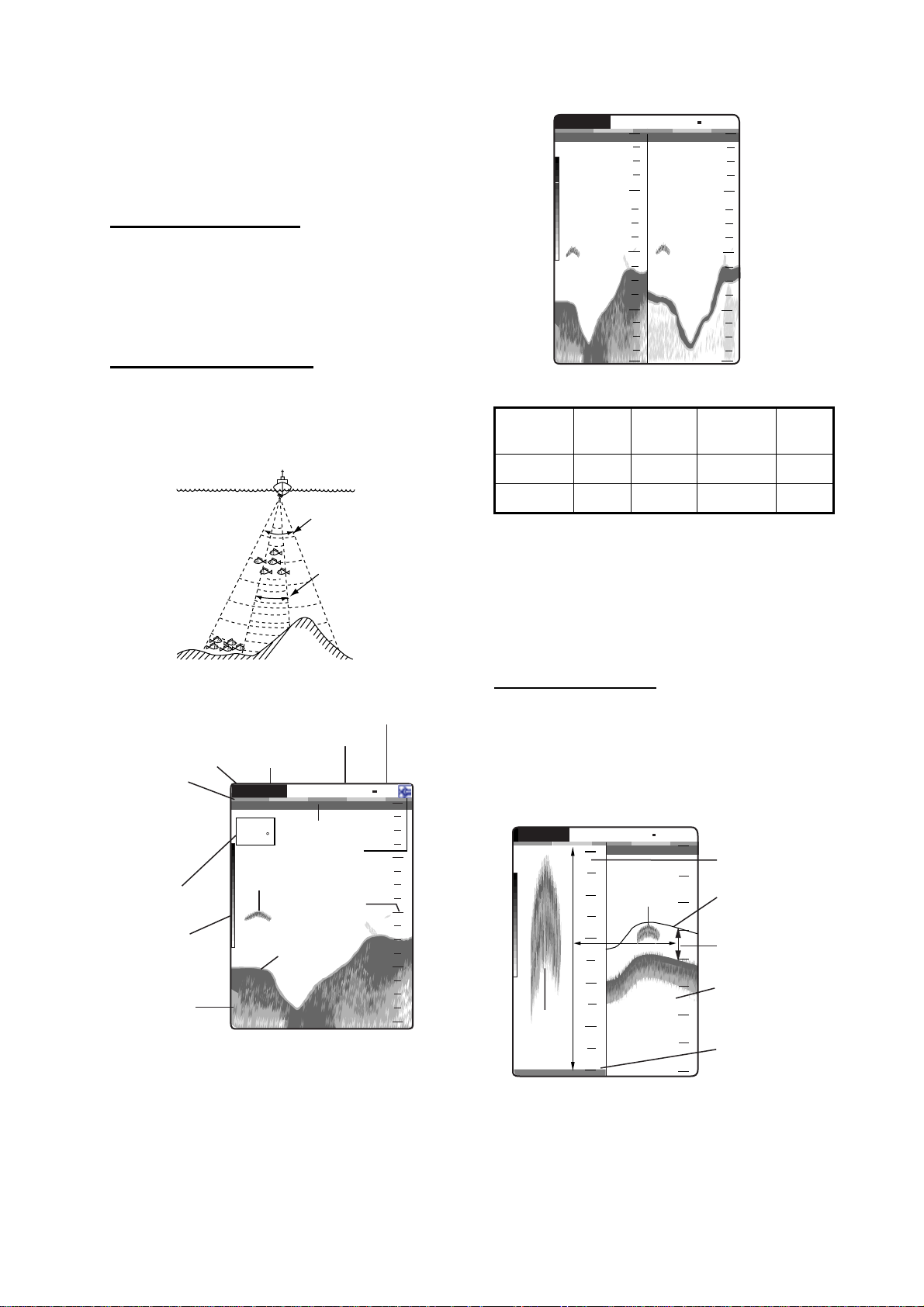
2. Rotate the MODE knob again to choose the
z
4
G
er
2
t
display mode desired.
The screen you chose appears soon thereafter.
Single frequency display
Low frequency (50 kHz)
:AF R:A
0
W
50/200 1/1
0.0
50 kHz 200 kHz
picture picture
20
1. OPERATION
0
20
The sounder uses ultrasonic signals to detect
40
40
bottom conditions. The lower the frequency of
the signal, the wider the detection area. Therefore, the 50 kHz frequency is useful for general
60
60
detection and judging bottom condition.
High frequency (200 kHz)
The higher the frequency of the ultrasonic
80
Dual frequency display
80
m
7.2
signal, the better the resolution. For this reason
the 200 kHz frequency is ideal for detailed
observation of fish schools.
Frequency
50 kHz Wide Low Deep Long
200 kHz Narrow High Shallow Short
Beam
width
Resolu-
tion
Detectable
range
Bottom
tail
50 kHz
Zoom display (50/200 kHz)
200 kH
Frequency and coverage area
Picture advance speed
Display mode
Gain
Minute
marker
(Each bar
equals
30 sec.)
Nav
display
Range
G:AF R:A
15.5 kt
Transmission line
82.6
Alarm icon
Fish school
Range scale
50k
0.0
W
1/1
0
20
40
Color
bar
Depth
Single frequency display
Dual frequency display
The 50 kHz picture appears on the left; the 200
kHz picture on the right. This display is useful for
Bottom
49.6
60
m
80
comparing the same picture with two different
frequencies.
Zoom mode expands chosen area of the single
frequency picture. Three modes are available:
bottom lock, bottom zoom and marker zoom.
The default mode is bottom lock. To change a
mode, see page 16.
Bottom lock display
The bottom lock display provides a normal picture on the right half of the screen and a 10-30
feet (default: 15 feet) wide layer in contact with
the bottom is expanded onto the left half of the
screen. This mode is useful for detecting bottom
fish.
G:AF R:A
Zoomed
fish
1.7
m
B/L-LF
5
4
3
2
1
0
Fish
school
1/1
0
10
20
30
40
0
Bottom lock
display
Zoom mark
This section
is zoomed.
Single
frequency
display
Bottom
displayed fla
W
Bottom lock display
Note1: To adjust the range of the zoom display,
go to the Range menu (see page 20).
Note2: To turn on or off the Zoom Marker, go to
the Display menu (see page 18).
3
Page 13
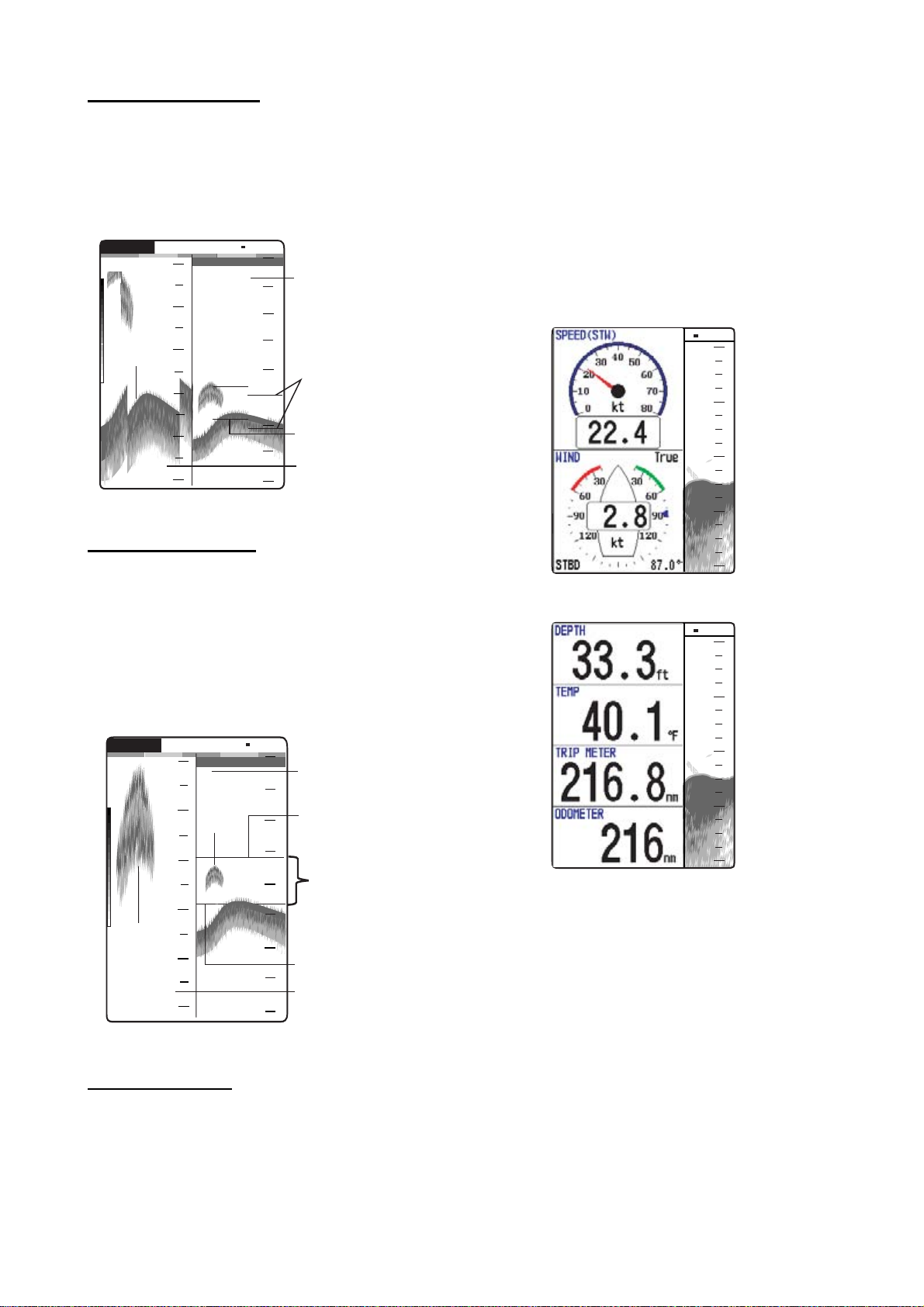
1. OPERATION
y
2
Bottom zoom display
This mode expands bottom and bottom fish on
the left-half window. This mode is useful for
determining bottom contour. When the bottom
depth increases, the display automatically shifts
to keep the bottom echo at the lower part of the
screen.
G:AF R:A
27
B/Z-LF
W
1/1
0
0
Single
frequency
display
Zoom
marker
Switched with
depth
Bottom zoom
display
Bottom
29.8
28
29
30
31
m
32
10
20
30
40
Bottom zoom display
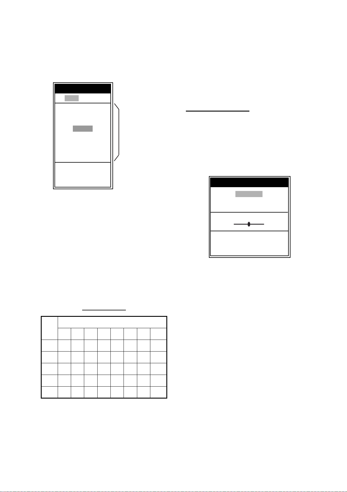
use on the Display menu. The default settings
are as follows.
Nav Data 1: Two-data display (SPEED (STW),
WIND)
Nav Data 2: Four-data display (DEPTH,
TEMPERATURE, TRIP METER,
ODOMETER)
You can display between two and four items in
a nav data display and choose the item and
order to display them. For details, see section
1.19.
W
1/1
0
20
40
60
Marker zoom display
This mode expands chosen area of the normal
picture to full vertical size of the screen on the
left-half window. You may specify the portion to
expand by operating the VRM (Variable Range
Marker), which you can shift with
S or T. The
area between the VRM and zoom marker is
expanded. This mode is useful for determining
the size of fish in the middle water.
W
G:AF R:A
17
M/Z-LF
1/1
0
0
Single frequenc
display
Fish
18
19
20
Zoomed
fish
21
school
m
5.0
22
school
17.0
10
20
30
40
Variable range
marker
This section
is zoomed
Zoom marker
Marker zoom
display
80
Nav Data 1 display
W
1/1
0
20
40
60
80
Nav Data 2 display
Sample Nav Data displays (Default setting)
Marker zoom display
Nav data displays
The nav data displays appear on the left of the
screen. Data other than depth requires appropriate sensor.
Two nav data displays are available, Nav Data
1 or Nav Data 2, and you may choose which to
4
Page 14
1. OPERATION
h
e.
1.5 Choosing Range
The basic range may be chosen in Auto or
Manual mode.
1. Press the RANGE key to open the range setting window.
Range
W Auto Manual X
15 ft
30 ft
60 ft
120 ft
200 ft
400 ft
600 ft
1000 ft
S
/ T : Select
[ENTER] : Set
[MENU] : Cancel
Range setting window
2. Use W or X to choose Auto or Manual.
Auto: The range changes automatically to
display the bottom echo on the screen. The
range shifting functions are inoperative in
Auto mode. “R:A” is shown at the top left
corner on the screen.
Manual: The range may be chosen from the
eight ranges. “R:M” is shown at the top left
corner on the screen.
If you choose Auto go to step 4. For manual
go to the next step.
3. For Manual, use
range.
S or T to choose the
Default ranges
Basic Range
Unit
1234567 8
m 5 10 20 40 80 150 200 300
ft 15 30 60 120 200 400 600 1000
fa 3 5 10 20 40 80 100 150
pb 3 5 10 20 50 100 150 200
HR* 4 8 15 30 50 100 150 200
*: Japanese unit of depth measurement
Note: Basic ranges may be preset as desired.
For further details, see page 20.
4. Press the ENTER key.
These are
available wit
Manual mod
Note: The range mode indication, which
appears at the top-left corner, may be turned on
or off with Header Info on the Display menu. For
details, see page 18.
1.6 Adjusting Gain
The gain may be adjusted automatically
(Fishing or Cruising) or manually.
Fishing and Cruising
The gain (or receiver sensitivity) is adjusted
automatically for Fishing and Cruising mode so
that the bottom is displayed as reddish brown.
Gain offset lets you override automatic gain
adjustment.
1. Press the GAIN knob to open the Auto Gain
setting window.
Auto Gain
Fishing
Cruising
Off
Offset 0
W Min Max X
S
/ T : Select
[ENTER] : Set
[MENU] : Cancel
Auto Gain setting window
2. Press the GAIN knob again to choose
Fishing or Cruising.
You may also use
mode.
Fishing: This mode clearly displays weaker
echoes and is for searching fish schools.
“G:AF” is shown at the top left corner on the
screen.
Cruising: This mode clearly displays
stronger echoes (for example, bottom), suppresses weak echoes and is for general
cruising.
“G:AC” is shown at the top left corner on the
screen.
Off: For manual adjustment
Adjusting gain offset proceed, if not go to
step 4.
3. If you need, adjust the gain offset with
X (setting range: -5 to +5).
Pressing W lowers the gain, X raises the
gain.
4. Press the ENTER key.
S or T to choose the
W or
5
Page 15
1. OPERATION
CAUTION
Currently selected menu
Manual gain adjustment
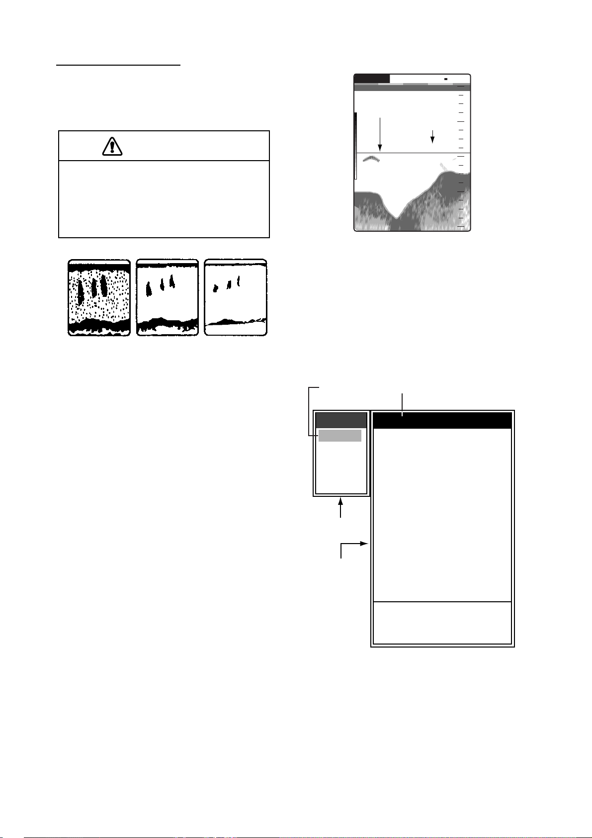
The GAIN knob adjusts the sensitivity of the
receiver. Generally, use a higher gain setting for
greater depths and a lower setting for shallower
waters.
Use the proper gain setting.
Incorrect gain may produce wrong depth
indication, possibly resulting in a
dangerous situation.
Gain too high
Gain proper
Gain too low
Examples of proper and improper gain
1. Press the GAIN knob to open the Auto Gain
setting window.
2. Press the GAIN knob again to choose Off.
“G:M” appears at the top left corner on the
screen.
3. Press the ENTER key.
4. Rotate the GAIN knob to adjust the gain. The
setting range is 0.0 to 10.
Adjust so that a slight amount of noise
remains on the screen.
The setting gain is shown at the top of the
screen as G (Gain) + XX (setting value).
1.7 Measuring Depth
The VRM (Variable Range Marker) functions to
measure the depth to fish schools, etc.
1. Use
2. Read the VRM depth just above the VRM.
S or T to place the VRM on the object
to measure depth.
G:AF R:A
VRM
49.6
Depth to VRM
m
50k
37.9
W
1/1
0
20
40
60
80
How to measure depth with the VRM
1.8 Menu Operating Procedure
The FCV-620/585 have five menus: Sounder,
Display, Alarm, Data, and System. Below is the
basic menu operating procedure.
1. Press the MENU/ESC key to open the menu.
Cursor
(yellow)
Menu
Sounder
Display
Alarm
Data
System
T
Menu window
Menu item
window
*: FCV-585
only
Sounder
Pic. Advance : 1/1
Zoom Mode
Shift
Bottom Area
Interference
Color Erase : 0%
Clutter
White Line : 0%
White Marker
TVG
Smoothing
TX Power : Auto
TX Rate
Transducer*
S
/ T / W / X : Select
[ENTER] : Enter
[MENU] : Back
: Bottom Lock
: 0ft
: Auto
: 0%
: Medium
: On
: 10
: 600W
Menu
2. Use S or T to choose the menu or sub
menu desired.
The cursor (yellow) shows current selection.
The items in the right window change with
menu selected.
3. Press the ENTER key.
The cursor (yellow) shifts to the menu item
window (right) and the current selection on
6
Page 16
the menu window (left) is displayed to gray.
W
s
d
s
You may also use
4. Use
S or T to choose the menu item
desired and press the ENTER key.
The selected setting box or window appears.
X to move the cursor.
Depth Size
1. OPERATION
Shift
Small
Medium
Large
Off
On
[ENTER] : Set
[MENU] : Cancel
Setting box Setting window
5. Use S or T to choose an option.
6. Press the ENTER key to save the setting.
The setting box or window disappears. To
escape without changing setting press the
MENU/ESC key instead of the ENTER key.
7. To choose another menu press the MENU/
ESC key.
The cursor (yellow) moves to the menu
window. You may also use
cursor.
8. Press the MENU/ESC key to close the
menu.
W to move the
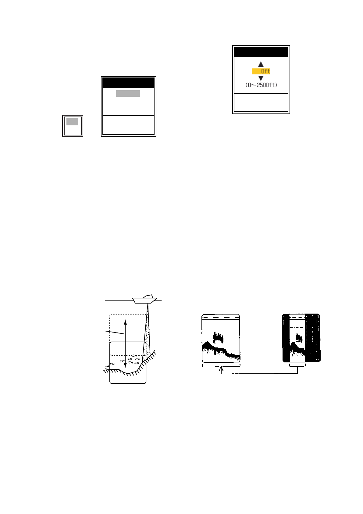
1.9 Shifting Range
The basic range may be shifted up or down in
the Manual mode as follows:
[ENTER] : Set
[MENU] : Cancel
Shift setting window
4. Use S or T to choose an amount of shift
desired and press the ENTER key.
5. Press the MENU/ESC key twice to close the
window.
Note: The echo may be lost if the amount of
shift is greater than actual depth.
1.10 Choosing Picture
Advance Speed
The picture advance speed determines how
quickly the vertical scan lines run across the
screen. When choosing a picture advance
speed, keep in mind that a fast advance speed
will expand the size of the fish school horizontally on the screen and a slow advance speed
will contract it. A fast advance speed is useful
for observing the rugged bottom minutely. A
slow advance speed is useful for observing the
smooth bottom.
indow can be
hifted up and
own to select
tarting depth.
Display
Range and display shift concept
Note: This function is inoperative when Auto
mode is selected on the range setting window.
1. Press the MENU/ESC key to open the menu.
2. Use
3. Use
S or T to choose Sounder and press
the ENTER key.
S or T to choose Shift and press the
ENTER key.
Fast
Slow
Picture and picture advance speed
1. Press the MENU/ESC key to open the menu.
2. Use
S or T to choose Sounder and press
the ENTER key.
7
Page 17
1. OPERATION
w
st
e
Sounder
Pic. Advance : 1/1
Zoom Mode
Shift
Bottom Area
Interference
Color Erase : 0%
Clutter
White Line : 0%
White Marker
TVG
Smoothing
TX Power
TX Rate
Transducer*
S
/ T / W / X : Select
[ENTER] : Enter
[MENU] : Back
: Bottom Lock
: 0ft
: Auto
: 0%
: Medium
: On
: Auto
: 10
: 600W
5. Press the MENU/ESC key twice to close the
window.
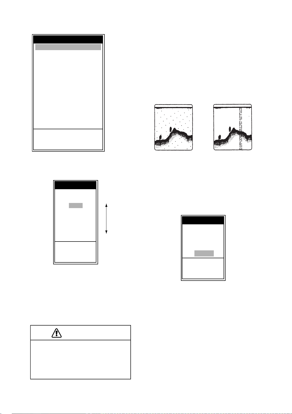
1.11 Suppressing
Interference
Interference from other acoustic equipment
operating nearby or other electronic equipment
on your boat may show itself on the display as
shown in the figure below. Follow the procedure
below to suppress interference.
*: FCV-585
only
Sounder menu
3. Use S or T to choose Pic. Advance and
press the ENTER key.
Pic. Advance
4/1
2/1
1/1
1/2
1/4
1/8
1/16
Stop
S
/ T : Select
[ENTER] : Set
[MENU] : Cancel
Fa
Slo
Pic. Advance setting window
4. Use S or T to choose picture advance
speed desired and press the ENTER key.
1/16 is the slowest speed and 4/1 is the
fastest speed. 1/16 means one scan line is
produced every 16 transmissions. Current
picture advance is displayed at the top-right
corner of the screen.
CAUTION
The picture is not refreshed when
picture advancement is stopped.
Maneuvering the vessel in this condition
may result in a dangerous situation.
Interference from
other sounder
Electrical interferenc
Interference
1. Press the MENU/ESC key to open the menu.
2. Use
3. Use
S or T to choose Sounder and press
the ENTER key.
S or T to choose Interference and
press the ENTER key.
Interference
Off
Low
Medium
High
Auto
S
/ T : Select
[ENTER] : Set
[MENU] : Cancel
Interference setting window
4. Use S or T to choose the degree of sup-
pression desired and press the ENTER key.
Off: Turn off interference rejector.
Low, Medium, High: High provides the
greatest degree of suppression and Low is
the smallest.
Auto: Interference is suppressed automatically.
Note: Turn off the interference rejector when no
interference exists, so as not to miss echoes
from small fish.
5. Press the MENU/ESC key twice to close the
window.
8
Page 18
1. OPERATION
s
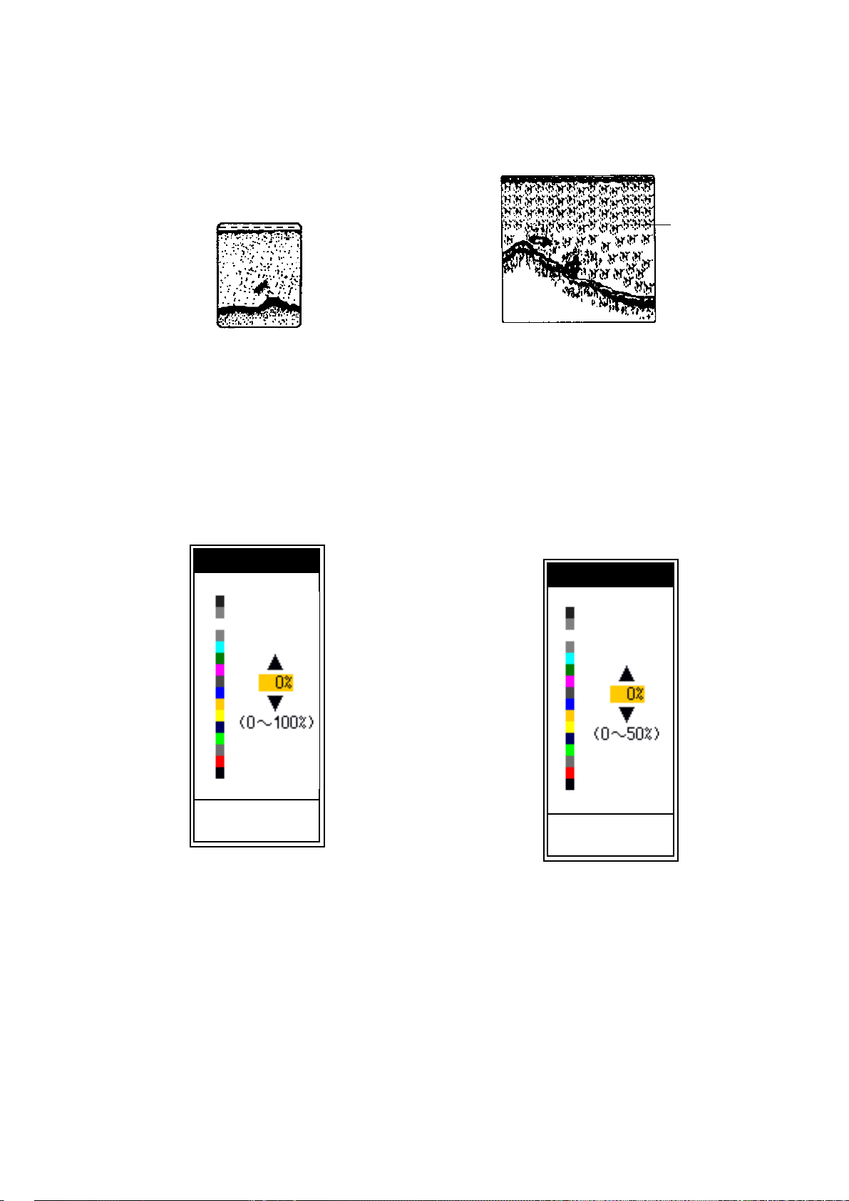
1.12 Suppressing Low Level Noise
Low intensity "speckles" may appear over most
of screen. This is mainly due to sediment in the
water or noise. These can be suppressed by
adjusting Clutter on the menu.
Clutter appearance
Note: Clutter cannot be adjusted when Fishing
or Cruising is selected on the Auto Gain setting
window.
1. Press the MENU/ESC key to open the menu.
2. Use
3. Use
S or T to choose Sounder and press
the ENTER key.
S or T to choose Clutter and press the
ENTER key.
Clutter
1.13 Erasing Weak Echoes
Sediment in the water or reflections from
plankton may be painted on the display in low
intensity tones.
Weak
echoe
Appearance of weak echoes
These weak echoes may be erased by using the
“Color Erase”. This function erases weaker
echoes sequentially to show only strong echoes
and clear up the picture.
1. Press the MENU/ESC key to open the menu.
2. Use
3. Use
S or T to choose Sounder and press
the ENTER key.
S or T to choose Color Erase and
press the ENTER key.
Color Erase
[ENTER] : Set
[MENU] : Cancel
Clutter setting window
4. Use S or T to choose the degree of sup-
pression desired and press the ENTER key.
The setting range is 0 to 100 % in intervals of
ten. The larger the setting value, the greater
the degree of suppression.
5. Press the MENU/ESC key twice to close the
window.
[ENTER] : Set
[MENU] : Cancel
Color Erase setting window
4. Use S or T to choose the color to erase and
press the ENTER key. The setting range is 0
to 50 % in intervals of five. The larger the setting value, the greater the degree of erasion.
5. Press the MENU/ESC key twice to close the
window.
9
Page 19
1. OPERATION
5
y
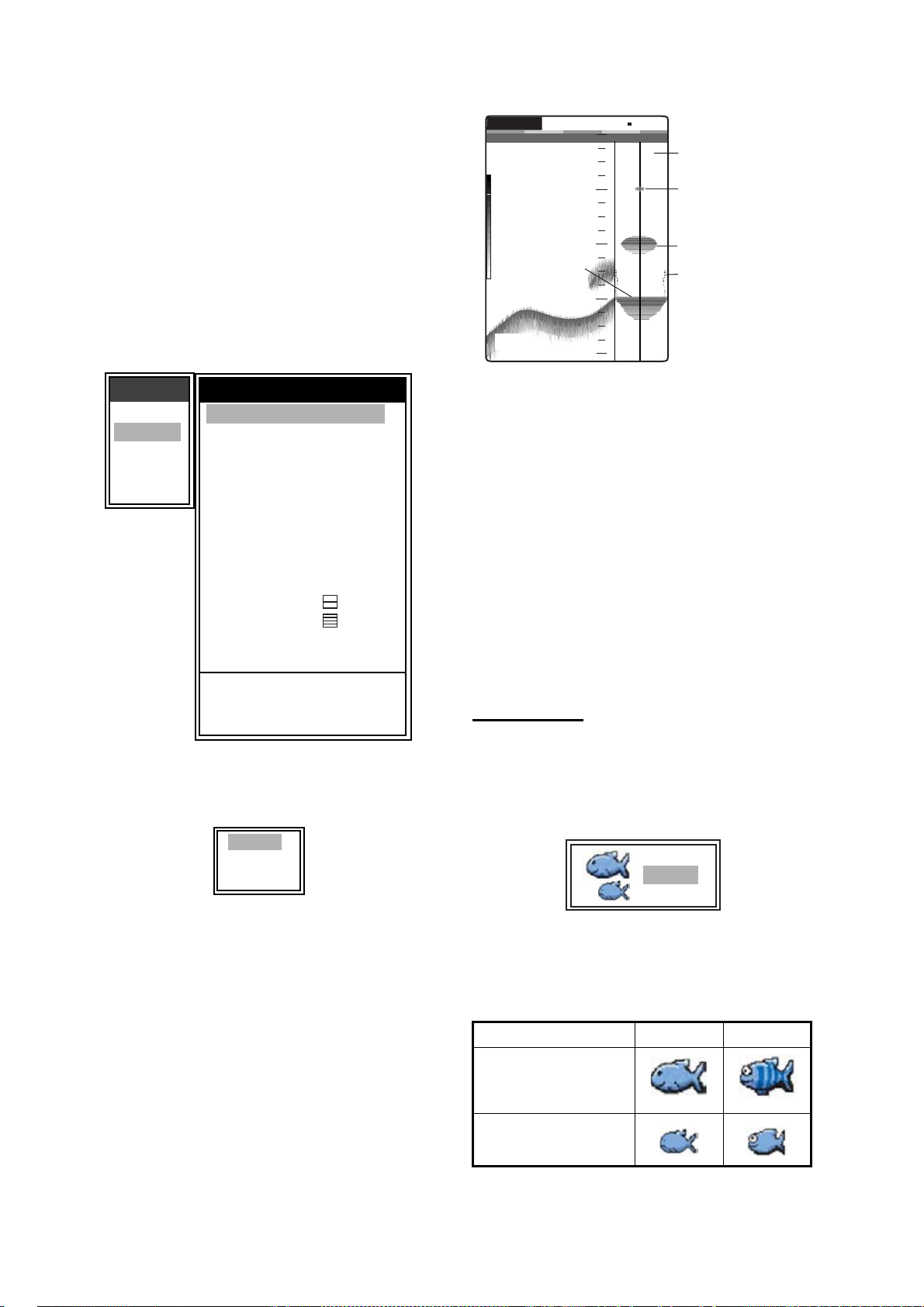
1.14 A-Scope Display
This display shows echoes at each transmission
with amplitudes and tone proportional to their
intensities, on the right of the screen. It is useful
for estimating the kind of fish school and bottom
composition.
Note: In the dual frequency display, the AScope display is only available with the high frequency display.
1. Press the MENU/ESC key to open the menu.
2. Use
S or T to choose Display and press the
ENTER key.
G:AF R:A
Single
frequency
display
Strong echo
(bottom)
9.8
m
0.0
20
40
60
80
50k
0
W
1/1
A-Scope displa
Weak echo
(small fish
school or
noise)
School fish
Past amplitude
pictures are
displayed with
dots with Peak
mode.
Menu
Sounder
Display
Alarm
Data
System
T
Display
A-Scope
Depth Size
Zoom Marker : Off
Temp Graph
Window Size
Battery : Off
Color Bar
Palette
Colors : 64
Header Info
Nav Data1
Nav Data2
Fish Info
Fish Symbols : Off
S
/ T / W / X : Select
[ENTER] : Enter
[MENU] : Back
: Off
: Small
: Off
: On
: White
: On
:
:
: Off
Display menu
3. Use S or T to choose A-Scope and press
the ENTER key.
Off
Normal
Peak
A-Scope setting box
4. Use S or T to choose the A-Scope presen-
tation type desired and press the ENTER
key.
Normal: Display shows echoes at each
transmission with amplitudes and tone proportional to their intensities.
Peak: “Normal” A-Scope display plus peakhold amplitude picture for last five seconds in
dots.
5. Press the MENU/ESC key twice to close the
window.
A-Scope display
Note: To turn off the A-Scope display, choose
Off at step 4 and then press the ENTER key.
1.15 Fish Information
You can turn the fish symbol indication (Solid or
Striped) on or off. Also, you can show or hide
the fish level and the depth value. For details
about the Fish Symbols, see the information
which follows the procedures in this section.
Note: The fish level found by this sounder is
intended for reference purposes; it is not an
accurate measurement of fish length.
Fish Symbols
1. Press the MENU/ESC key to open the menu.
2. Use
3. Use
4. Use S or T to choose Solid or Striped and
S or T to choose Display and press the
ENTER key.
S or T to choose Fish Symbols and
press the ENTER key.
Off
Solid
Striped
Fish Symbols setting box
press the ENTER key.
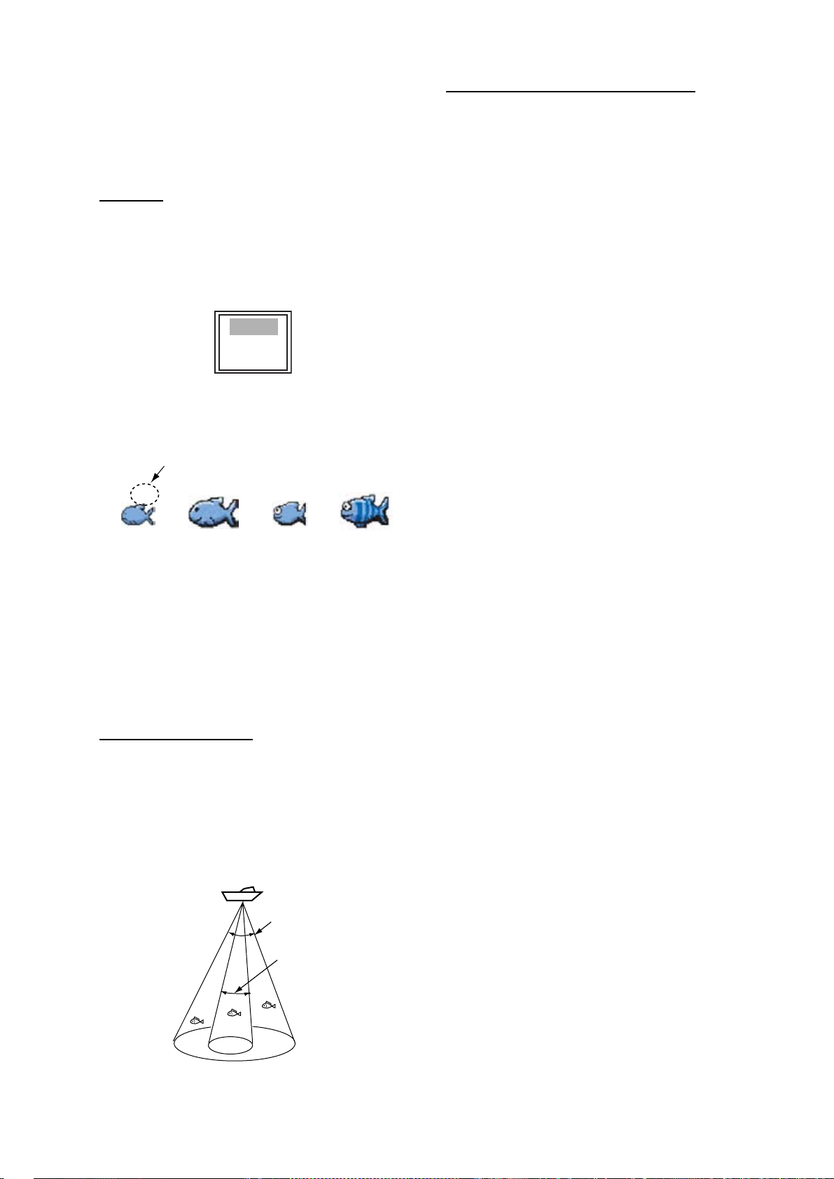
The level of fish symbol depends on the fish
size.
Symbol size, level Solid Striped
Large fish symbol
(more than 50),
[more than 20]
Small fish symbol
(10 to 49), [4 to 19]
( ): Level range for meter unit
[ ]: Level range for feet unit
10
Page 20
1. OPERATION
f
l)
Level or depth is displayed in red.
z
Note: To hide the fish symbol, choose Off at
step 4 and press the ENTER key.
5. Press the MENU/ESC key twice to close the
window.
Fish Info
1. Press the MENU/ESC key to open the menu.
2. Use
3. Use
S or T to choose Display and press the
ENTER key.
S or T to choose Fish Info and press
the ENTER key.
Off
Level
Depth
Fish Info setting box
4. Use S or T to choose Level or Depth and
press the ENTER key.
15
Solid
(Small
ish symbol)
60
Solid
(Large
fish symbol)
15
Striped
(Small
fish symbol)
60
Striped
(Large
fish symbo
Level and Depth fish symbols
Note: When selecting Off on Fish Symbols
menu, only level or depth is displayed.
Consideration for fish information
• The 600 W transducers which offer level
calculation are 520-5PSD, 520-5MSD, 5255PWD, 525ST-MSD and 525ST-PWD.
• For 1 kW transducer, the integrated type
50/200-1T is recommended to display the
fish symbol and the fish level. When using
both 50B-6 and 200B-5S, they should be
installed in close proximity to each other.
• Echo intensity depends on fish specie.
When the fish level differs between the indicated value and the fish caught, you can
compensate it on the Calib menu (see section 2.6).
• When Fish Symbols or Fish Info are
enabled, 50 kHz and 200 kHz beams are
transmitted alternately even if a single frequency mode is in use.
• To reduce error the detection area should
be 2 to 100 meters from the surface.
• With the inside-hull transducer, signal
attenuation is different between 50 kHz and
200 kHz. Therefore, a fish may not be
detected or the fish level indicated may be
smaller than actual level.
• In case of a fish school, echoes overlap one
another, so the margin of error will be
greater.
5. Press the MENU/ESC key twice to close the
window.
Principle of fish level
Returning echoes at the center of the transducer beam are used in fish level calculation.
Fish for level calculation are taken from the 200
kHz beam and their level is calculated from their
strengh found with the 50 kHz beam. In the
example below, only the fish at the center of the
figure is used for level calculation.
Principle
50 kHz
200 kH
1.16 Alarms
The FCV-620/585 have six conditions which
generate both audio and visual alarms: bottom
alarm, normal fish alarm, bottom lock fish alarm,
water temperature alarm, speed alarm and
arrival alarm. (The water temperature, speed
and arrival alarms require appropriate sensors.)
To silence the buzzer press any key.
Bottom alarm: The bottom alarm alerts you
when the bottom displayed in red or reddish
brown echo is within the alarm range set. To
activate the bottom alarm the depth must be displayed.
Fish (normal) alarm: The fish (normal) alarm
tells you when an echo above a certain strength
(selectable) are within the preset alarm range.
See page 13 for alarm level setting.
Fish (bottom lock) alarm: The fish (bottom
lock) alarm sounds when fish are within a certain distance from the bottom. Note that the
bottom lock display must be turned on to use
this alarm.
11
Page 21
1. OPERATION
n
or
B
d
*
Water temperature alarm: The water temperature alarm alerts you when the water temperature is within (inside alarm) the alarm range set
or under/over (outside alarm) the range set.
Speed alarm: The speed alarm alerts you when
the speed is within (inside alarm) or under/over
(outside alarm) the preset speed.
Arrival alarm: The “Inside” arrival alarm alerts
you when you approach to the destination waypoint by the distance set. Alternatively, the “Outside” arrival alarm alerts when you go away
from the preset range from a certain position.
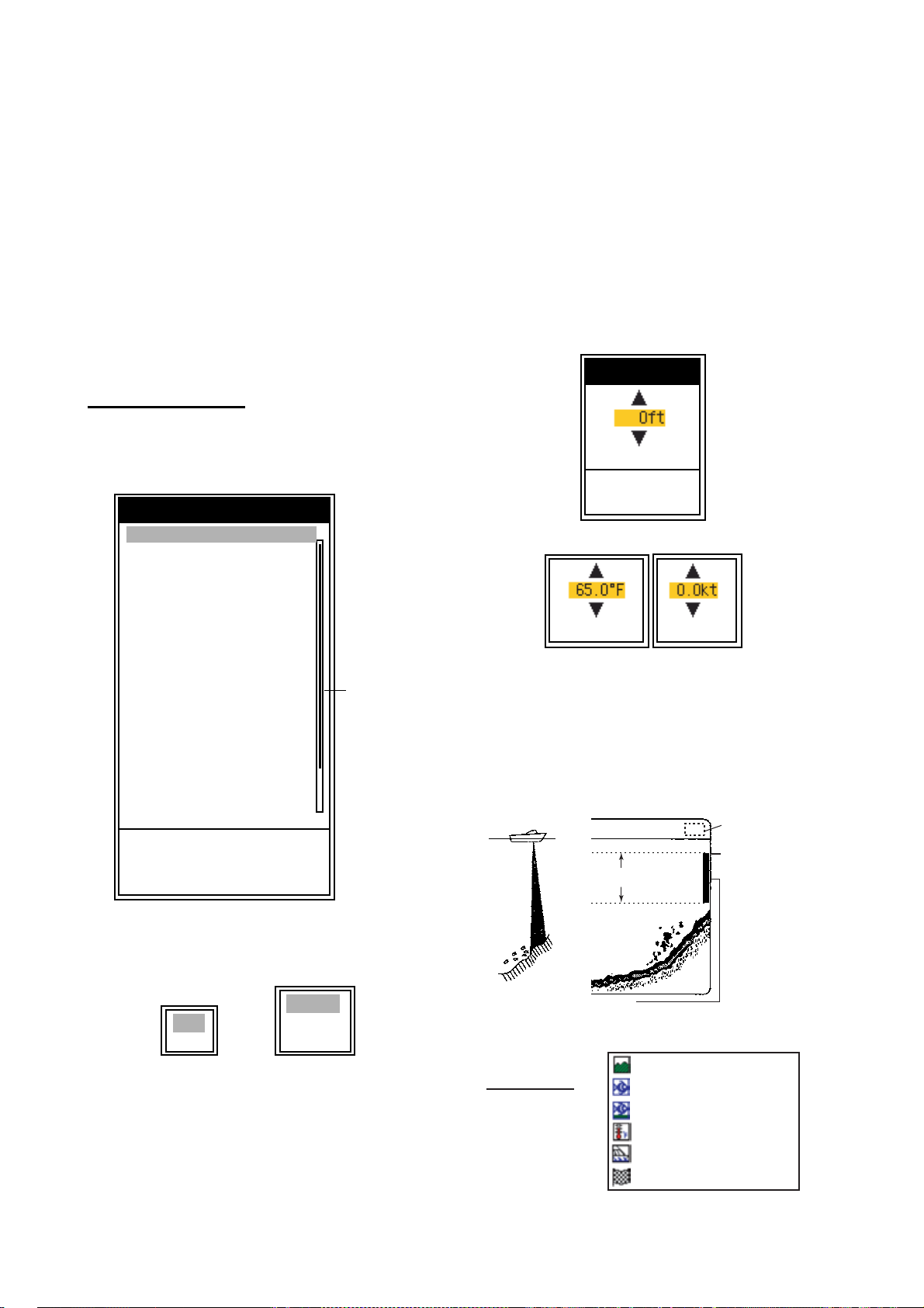
Activating an alarm
1. Press the MENU/ESC key to open the menu.
2. Use
S or T to choose Alarm and press the
ENTER key.
Alarm
Bottom : Off
From : 0ft
Span
Fish (Normal)
From
Span
Fish (B/L)
(Only at B/L mode)
From
Span
Fish Level
Temperature
From
Span
Speed
From
S
/ T / W / X : Select
[ENTER] : Enter
[MENU] : Back
: 10ft
: Off
: 0ft
: 10ft
: Off
: 0.0ft
: 1.0ft
: Medium
: Off
: 65.0°F
: 1.0°F
: Off
: 0.0kt
S
Menu
locatio
indicat
S
4. Use S or T to choose alarm type:
Off: Alarm off
On: Alarm on
Inside: Alarm generated when speed, water
temperature or arrival distance is within the
range set.
Outside: Alarm generated when speed,
water temperature or arrival distance is outside the range set.
5. Press the ENTER key.
For Arrival Alarm, go to step 8.
6. Use
T to choose From and press the
ENTER key.
From
(0∼2500ft)
[ENTER] : Set
[MENU] : Cancel
Depth setting window
(20.0∼110.0°F)
Temperature
(0.0∼99.0kt)
Speed
Temperature, Speed setting box
7. Use S or T to set starting depth, temperature or speed as appropriate and press the
ENTER key. For Bottom and Fish (Normal),
the starting depth is the range from the transducer, and for Fish (B/L), from the bottom.
Alarm icon
Starting
Alarm range
point
Alarm menu
3. Use S or T to choose an alarm desired and
press the ENTER key.
Alarm range marker
z Bottom alarm, Fish alarm (normal): Right
z Fish alarm (B/L): Center
: Bottom alarm
* Alarm icon
(Appropriate icon
appears to show
which alarm has
been violated.)
: Fish alarm (normal)
: Fish alarm (B/L)
: Temperature alarm (°F)
: Speed alarm
Off
On
Fish and
ottom Alarm
Alarm options
Off
Inside
Outside
Temp, Speed an
Arrival Alarm
: Arrival alarm
How the alarm works
12
Page 22
1. OPERATION
Depth and temperature of cursor position
8. Use T to choose Span (or Radius for Arrival)
and press the ENTER key.
9. Use
10.For the bottom alarm, temperature alarm,
11.Use
S or T to set the range of depth, tem-
perature, speed or distance as appropriate.
To shorten the alarm range marker use
and to lengthen use
speed alarm or arrival alarm, press the
ENTER key to finish, and then go to step 13.
For a fish alarm, press the ENTER key and
go to step 11.
S.
T,
T to choose Fish Level and press the
ENTER key.
Weak
Medium
Strong
Fish Level setting box
12.Use S or T to choose the echo strength
level which will trigger a fish alarm and press
the ENTER key.
Weak: Light-blue or stronger echoes
Medium: Yellow or stronger echoes
Strong: Red and reddish brown echoes
13.Press the MENU/ESC key twice to close the
window.
Note1: To disable an alarm, choose Off at step
4 in the above procedure.
1.18 Waypoints
Waypoints may be used to:
• Record the position of an important echo as
waypoint. 20 points may be registered.
• Output a waypoint position to a plotter to
mark position on its screen.
• Find range, bearing and time-to-go to a
location (waypoint).
Note: Requires latitude and longitude position
from a navigator.
1.18.1 Registering a waypoint
Registering a waypoint on the screen
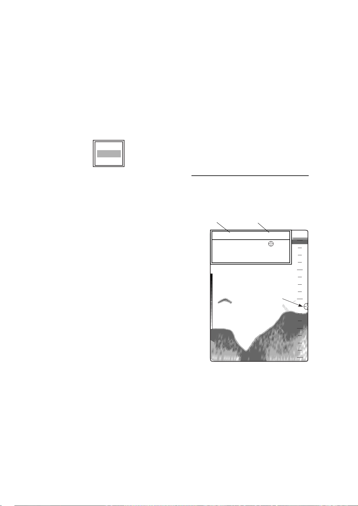
1. Press the MARK key.
The cursor appears along with waypoint
entry instructions. To enter a waypoint to the
current own ship's position, go to step 3.
45.0m 50.0°F
S
/ T / W / X : Move cursor
[ENTER] / [MARK] : Set
[MENU] : Cancel
0
20
Note2: The audio and visual alarms are
released against the last-violated alarm when
multiple alarms are active.
1.17 FUNC Key
The FUNC key provides for instant display of a
user-defined options window chosen with
FUNC Key on the Key menu. Nine items are
available: Pic. Advance (default), Shift, Interference, Clutter, Color Erase, White Line, White
Marker, WPT List and Bottom Area. For details
about registration, see section 2.2. Use the
FUNC key as follows.
1. Press the FUNC key to open the setting
window registered; for example, Pic.
Advance setting window.
2. Use FUNC key,
and press the ENTER key.
S or T to adjust the setting
49.6
Cursor
m
40
60
80
Cursor
Note: If there is no position data the message
"No position data!" appears. Check the navigator.
2. Press the TrackPad to set the cursor where
desired.
Picture advancement is stopped until step 3
is completed, and the instruction window is
integrated into the nav display.
13
Page 23
1. OPERATION
3. Press the MARK or ENTER key to register
the position set at step 2.
A red vertical line appears on the position set
at step 2. The waypoint is named automatically with the next sequential waypoint
number. If you want to change waypoint
name, go to step 4. Otherwise, go to step 6.
New Waypoint
Name : 01
Lat : 34°22.796'N
Lon : 136°07.264'E
Erase?
S
/ T : Select
[ENTER] : Enter
[MENU] : Quit
Waypoint setting window
Note1: When TLL or FURUNO-TLL is selected
at TLL Output on the NMEA menu of the System
menu, the latitude and longitude position at the
cursor position is output to the navigator.
Note2: If you attempt to enter 21st waypoint, the
message "Already entered 20 waypoints. No
more waypoint can be entered." appears. In this
case, erase an unwanted waypoint to enable
entry. See paragraph 1.18.3 for details.
Data
Go to WPT : Off
WPT List
Nav Display1
Nav Display2
Bearing
Wind Spd/Dir
Trip Source
Temp Source
: Off
: Off
: True
: True
: Own
: Own
Speed Source : Own
Trip Reset
Odo Reset
S
/ T / W / X : Select
[ENTER] : Enter
[MENU] : Back
Data menu
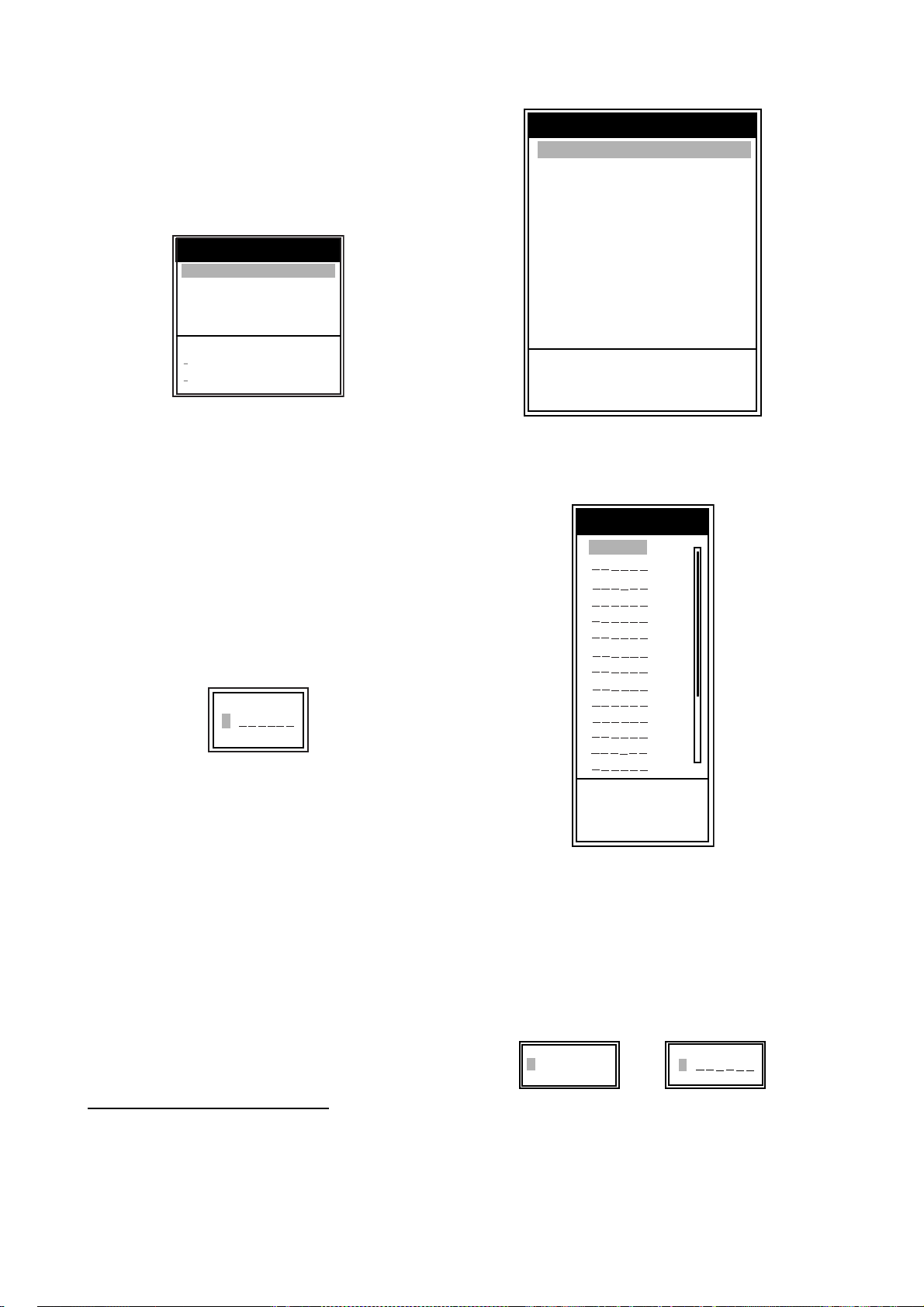
3. Use S or T to choose WPT List and press
the ENTER key.
WPT List
01
S
4. Press the ENTER key to to open the waypoint name entry box.
S
01
T
Waypoint name entry box
5. Enter the waypoint name (Max. 8 characters).
a) Use
S or T to set character. When
pressing
S, character order is 0 → 1 → ...
→ 9 → - → A → ... → Z → _ → 0 → ....
When pressing
reverse.
b) Use
X to shift cursor.
c) Repeat step a) and b) to set the name
desired and press the ENTER key.
Press the MENU/ESC key to close the
6.
window.
T, character order is
S
S
/ T : Select
[ENTER] : Enter
[MENU] : Quit
WPT List window
4. Use S or T to choose an empty waypoint
and press the ENTER key.
The Waypoint setting window appears. Lat
and Lon indicate the current position.
5. Use
S or T to choose item desired and
press the ENTER key.
The character setting box is shown.
S
34°22.796'N
S
S
02
S
Registering a waypoint by L/L
1. Press the MENU/ESC key to open the menu.
2. Use
S or T to choose Data and press the
ENTER key.
For L/L For waypoint name
6. Enter latitude and longitude, similar to how
you entered the waypoint name.
7. Press the MENU/ESC key four times to close
the window.
14
Page 24

1. OPERATION
I
*,
w
w
,
p
t
a
w
I
n,
s
r
w
w
d
*
1.18.2 Editing a registered waypoint
1. Press the MENU/ESC key to open the menu.
2. Use
3. Use
4. Use
5. Use
6. Edit latitude and longitude, similar to how
7. Press the MENU/ESC key four times to close
S or T to choose Data and press the
ENTER key.
S or T to choose WPT List and press
the ENTER key.
S or T to choose a waypoint to be
edited and press the ENTER key.
The Edit Waypoint window is shown.
S or T to choose item desired and
press the ENTER key.
you entered the waypoint name.
the window.
1.18.3 Erasing waypoint
To erase a waypoint do the following:
1. Do steps 1 through 4 in 1.18.2.
2. Use
3. Use
4. Press the MENU/ESC key three times to
T to choose the Erase? and press the
ENTER key.
S to choose Yes and press the ENTER
key.
close the window.
1.18.4 Setting destination waypoint
Set a destination waypoint to find range, bearing
and time-to-go to that point. Range, bearing
and time-to-go (to the waypoint) are shown on
the nav data display. See next section for
details.
1. Press the MENU/ESC key to open the menu.
2. Use
3. Use
4. Use
5. Press the MENU/ESC key twice to close the
S or T to choose Data and press the
ENTER key.
S or T to choose Go to WPT and press
the ENTER key.
S or T to choose a destination way-
point and press the ENTER key.
window.
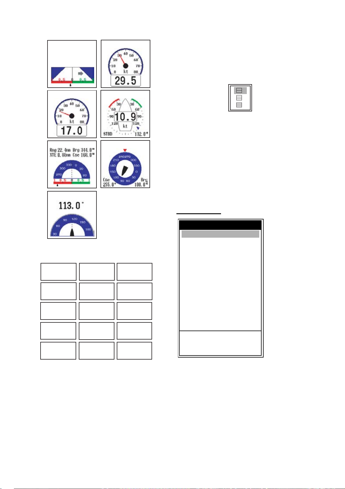
1.19 Setting Up Nav Data Displays
The user may arrange the nav data displays as
desired.
1.19.1 Nav data displays
1. Rotate the MODE knob to choose NAV1 or
NAV2.
S
/ T : Window Selection
W
/ X : Data Selection
[ENTER] : Set
[MENU] : Cancel
Nav Data setting window
Note: The setting window disappears if there is
no operation for five seconds. In this case press
the TrackPad to re-display the window.
2. Use
3. Use
S or T to choose a data display
window desired.
W or X to choose item to display.
Items displayable depend on the screen division.
(1)
(2)
Two-data
display
tems displayable in (1) - (3): speed (STW)
ind speed and direction*, destination
aypoint data*, compass*, heading*, depth
osition, course, range and bearing,
rip meter, odometer, water temperature,
ir pressure, time-to-go to destination
aypoint, XTE*, speed (SOG)*
tems displayable in (4) - (9): depth, positio
peed (SOG), speed (STW), course,
ange and bearing, trip meter, odometer,
ater temperature, heading, wind speed,
ind direction, air pressure, time-to-go to
estination waypoint, XTE
= Graphic display
(3)
(4)
(5)
Three-data
display
(6)
(7)
(8)
(9)
Four-data
display
4. Press the ENTER key.
15
Page 25
1. OPERATION
e
XTE MARINA
XTE
0.20
Rng
27.3
PORT
nm
nm
SPEED (SOG)
1.19.2 Screen division
1. Press the MENU/ESC key to open the menu.
2. Use
3. Use
S or T to choose Display and press the
ENTER key.
S or T to choose Nav Data 1 or Nav
Data 2 and press the ENTER key.
SPEED (STW)
WPT MARINA
HEADING True
DEPTH
1234ft
SPEED (STW)
12.3kt
TRIP METER
1234nm
HEADING True**
123.4
BAROM PRESS
1234
hPa
WIND True
COMPASS True
SOG: Speed over
ground
STW: Speed relativ
to water
Graphic displays
POSITION
°
23 45.6789
°
123 45.6789
COURSE True**
N
E
°
123.4
ODOMETER
1234nm
WIND SPEED True*
°
12.3kt
TIME TO GO
12H34M
SPEED (SOG)
12.3kt
RNG/BRG***
°
1234nm123.4
TEMP
123.4 F
WIND DIR. True*
123.4
XTE
X
0.50nm
°
°
X
Nav Data setting box
4. Use S or T to choose screen division
desired and press the ENTER key.
5. Press the MENU/ESC key twice to close the
window.
1.20 Menu Items
This section describes menu items not previously mentioned. For the System menu, see
chapter 2.
Sounder menu
Sounder
Pic. Advance : 1/1
Zoom Mode
Shift
Bottom Area
Interference
Color Erase : 0%
Clutter
White Line : 0%
White Marker
TVG
Smoothing
TX Power
TX Rate
Transducer*
S
/ T / W / X : Select
[ENTER] : Enter
[MENU] : Back
: Bottom Lock
: 0ft
: Auto
: 0%
: Medium
: On
: Auto
: 10
: 600W
*: FCV-585
only (see
section
4.10.)
* : APP or TRUE, depending
on menu setting.
** : TRUE or MAG depending
on menu setting.
*** : To destination waypoint.
Digital displays
Note: When data is lost 30 sec., the display
shows “- -” at the location where data is lost.
Sounder menu
Zoom Mode: Choose the zoom display to show
among bottom lock, bottom zoom and marker
zoom when “zoom” is chosen with the MODE
knob. For details, see page 3 and 4.
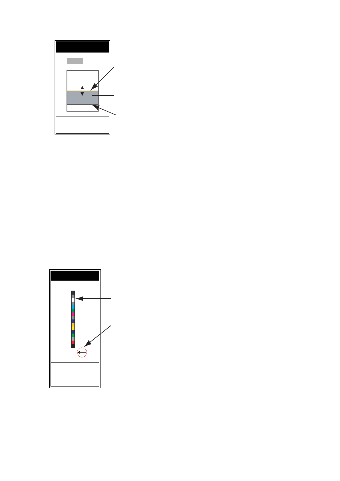
Bottom Area: Set the area where to display the
bottom echo when selecting Auto mode on the
RANGE key.
1. Choose Bottom Area in the Sounder menu
and press the ENTER key.
16
Page 26
Bottom Area
r
.
W Above Below X
Border (above)
Bottom area
Border (below)
[ENTER] : Set
[MENU] : Cancel
Bottom Area setting window
2. Use W or X to choose the border desired
(Above or Below).
3. Use
S or T to move upper or lower border
and press the ENTER key.
White Line: Displays the leading edge of the
bottom echo in white. This is useful for discriminating bottom fish from bottom. The setting
range is 0 to 50 % in intervals of five. The larger
the numeric, the wider the white line width.
White Marker: Displays the chosen echo color
in white.
1. Choose White Marker in the Sounder menu
and press the ENTER key.
White Marker
Color bar
Choose echo colo
to display in white
Off
1. OPERATION
changed to white. That color is also white on
the color bar.
To turn off the white marker, choose Off at step
2.
TVG: The fish schools of the same size are displayed in different color between in deep water
and in shallow water because of the feature of
the ultrasonic waves. TVG compensates for
propagation attenuation of the ultrasonic waves.
It does this by equalizing echo presentation so
that fish schools of the same size appear in the
same density in both shallow and deep waters.
The gain is adjusted automatically depending
on the depth. The gain is low at short distance
and getting back with increasing distance. High
provides the greatest degree of gain reduction
against short range echoes. Note that this function is operative when manual is selected on the
GAIN knob.
Smoothing: Smoothes echo presentation
when enabled. Adjust the setting when echoes
appear “spotty”.
TX Power: Interference may appear on the
screen when an echo sounder having the same
frequency as your own is being operated in the
vicinity of your vessel. In this case, lower your
TX power and contact the vessel to request
them to reduce their TX power. The higher the
numeric the greater the TX power. The "Auto"
setting automatically adjusts TX power with
depth. Note that this function is only operative
when Fish Info and Fish Symbols in the Display
menu are off. When Fish Info and Fish Symbols
are on, the TX power mode is “Auto”.
TX Rate: Changes pulse repetition rate. Normally, the highest rate (10) is used. When in
shallow waters second reflection echoes may
appear between surface and actual bottom
echo. In this case, lower the TX rate level.
The choice "S" means the ship's speed dependent mode, where the TX rate changes automatically with ship's speed. (Requires ship's
speed input.)
S
/ T : Select
[ENTER] : Set
[MENU] : Cancel
White Marker setting window
2. Use S or T to choose color desired and
press the ENTER key.
For example, move the arrow to the top of
the color bar to display the bottom in white.
The echo color chosen on the color bar is
17
Page 27
1. OPERATION
T
S
e
G
Display menu
Display
A-Scope : Off
Depth Size
Zoom Marker
Temp Graph
: Small
: Off
: Off
Window Size
Battery
Color Bar
Palette
Colors
Header Info
Nav Data1
Nav Data2
Fish Info
: Off
: On
: White
: 64
: On
:
:
: Off
Fish Symbols : Off
S
/ T / W / X : Select
[ENTER] : Enter
[MENU] : Back
Display menu
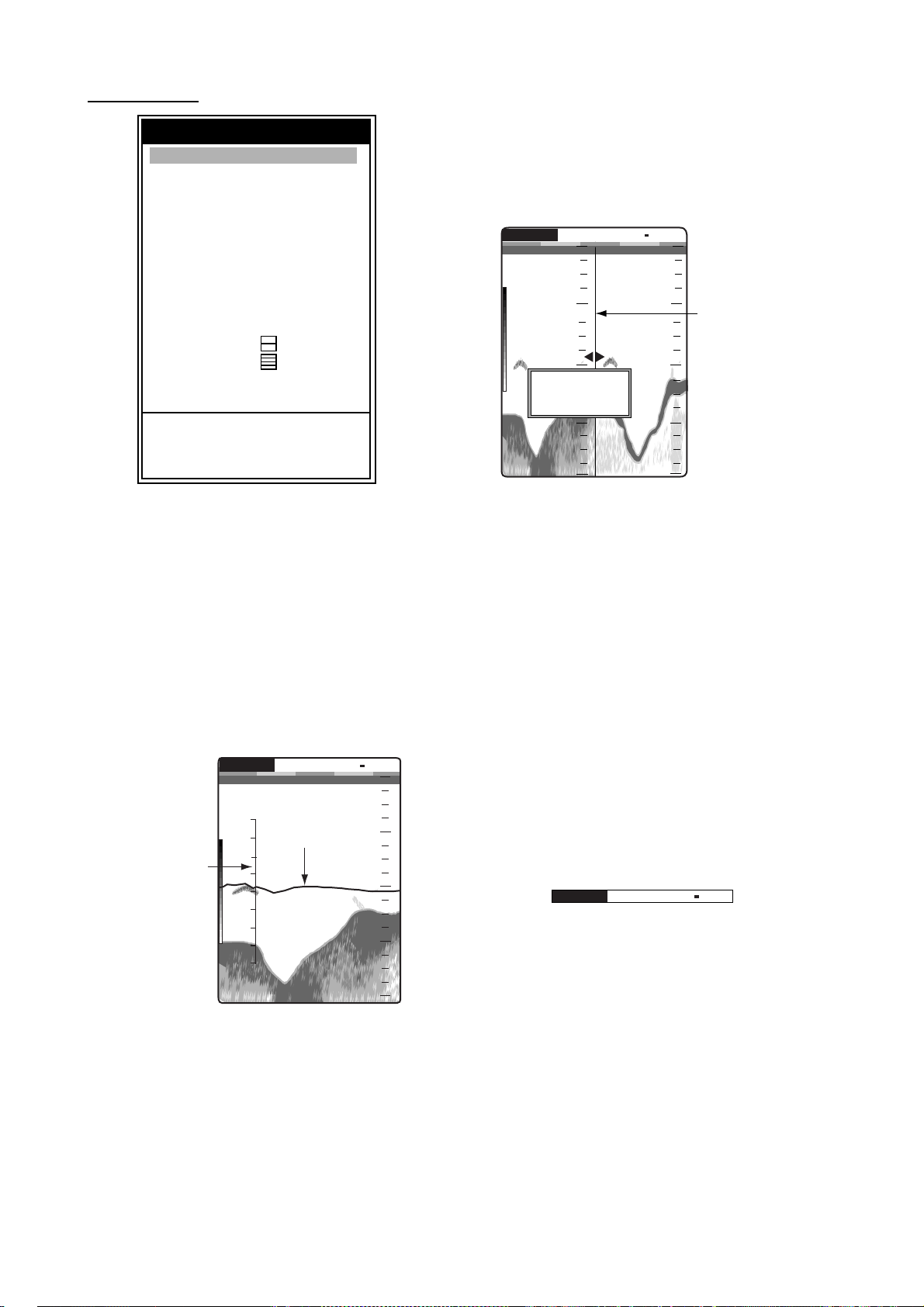
Depth Size: Choose the font size of the depth
indication (Small, Medium or Large).
Window Size: Adjust the display area of the
dual frequency mode or zoom mode. Note that
this function is inoperative with single frequency, nav data mode or A-Scope display.
1. Choose Window Size in the Display menu
and press the ENTER key.
G:AF R:A
0
20
W
50/200 1/1
0.0
20
0
Dividing lin
W
/ X : Adjust
[ENTER] : Set
[MENU] : Cancel
m
49.6
40
60
80
40
60
80
Window size setting window
2. Use W or X to move the dividing line and
press the ENTER key.
Zoom Marker: Turn the zoom marker on or off
(on the single frequency display) when the
bottom lock display, the bottom zoom display or
the marker zoom display is selected.
Temp Graph: Turn the water temperature
graph on or off. The temperature scale range is
° (°F) in “Narrow”, 32° (°F) in “Wide”.
16
Requires water temperature data.
50k
W
1/1
0
20
40
60
80
emperature
cale
G:AF R:A
56
48
40
32
24
49.6
Temperature
Graph
m
Battery: Turn the battery voltage indication
(appears at the top right corner on the screen)
on or off. When on it replaces the picture
advance speed indication.
Color Bar: Turn the color bar on or off.
Palette: Change the background color of the
screen in five colors: white, blue, black, gray
and night.
Colors: Choose the number of colors to use: 8,
16 or 64.
Header Info: Turn the data area indication
(appears at the top on the screen) on or off.
:AF R:A
W
50/200 1/1
Data area
Tempera t ure graph
18
Page 28
1. OPERATION
t
Data menu
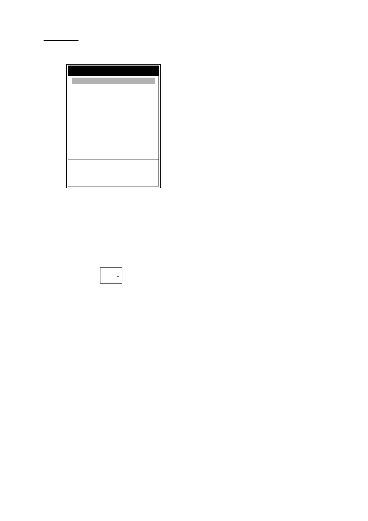
This menu mainly sets up how to display data
input by external equipment.
Data
Go to WPT : Off
WPT List
Nav Display1 : Off
Nav Display2 : Off
Bearing
Wind Spd/Dir
Trip Source
Temp Source
Speed Source
Trip Reset
Odo Reset
S
/ T / W / X : Select
[ENTER] : Enter
[MENU] : Back
: True
: True
: Own
: Own
: Own
Data menu
Nav Display 1, 2: Data for speed (SOG), speed
(STW), depth, range, bearing, position, wind,
heading, course, barom press, water temperature, time to go, trip meter, odometer or XTE can
be displayed on the left top of the screen.
Appropriate sensor is required to display data
other than depth.
Temp Source: Choose source of water temperature input; Off, Own (temperature sensor connected to the FCV-620/585) or NMEA (speed
data from external equipment).
Speed Source: Choose source of speed input;
Off, Own (speed sensor connected to the FCV620/585) or NMEA (speed data from external
equipment).
Trip Reset: Choose Yes to reset the trip distance to zero. Beeps are generated while the
trip distance is being reset.
Odo Reset: Choose Yes to reset the odometer
to zero. Beeps are generated while the odometer is being reset.
15.5 k
82.6
Data box
Bearing: Ship's course and heading may be
displayed in true or magnetic bearing. Magnetic
bearing is true bearing plus (or minus) earth's
magnetic deviation. Requires bearing data.
Wind Spd/Dir: Choose the wind speed and
direction reference from true and apparent.
Requires wind sensor.
Apparent: The direction (in relation to ship's
heading) and speed of the wind as it appears
to those on board, relative to the speed and
direction of the boat; combination of the true
wind and the boat's movement.
True: The speed and direction (in re la tion to
ship's heading) of the wind felt or measured
when stationary.
Trip Source: Choose speed source for the trip
distance indication: Off, Own (speed sensor
connected to the FCV-620/585) or NMEA
(speed data from external equipment).
19
Page 29
2. SYSTEM MENU
4.
3.
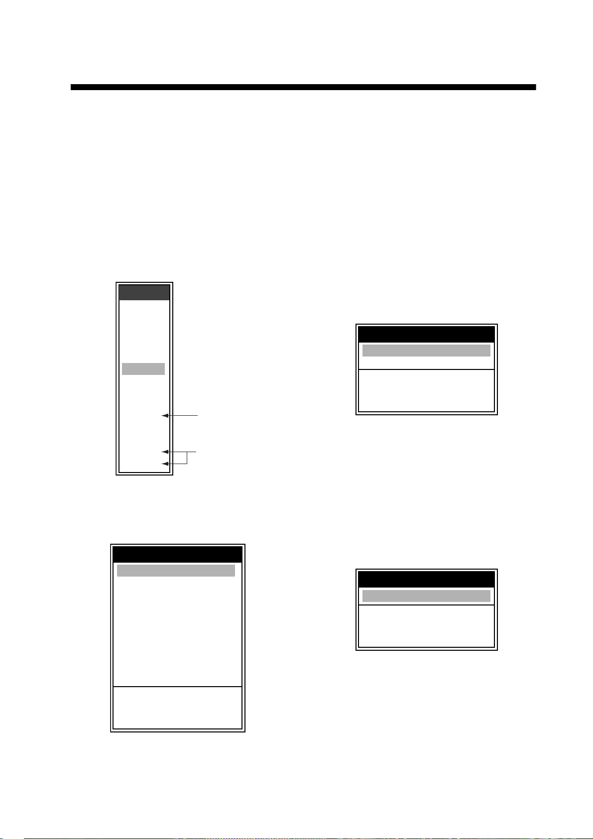
2.1 Displaying System Sub Menu
The System menu mainly consists of items
which once set do not require frequent adjustment. This menu has nine sub menus. To display each sub menu, do the followings.
1. Press the
menu.
2. Use S or T to choose System.
The list of sub menus appears below
System
MENU/ESC key to open the
.
Menu
Sounder
Display
Alarm
Data
T
System
Range
Key
Lang
Units
NMEA
Calib
Demo
Tests
Reset
Refer to
chapter
Refer to
chapter
System menu
Range 1 - Range 8: Set range of each of the
eight ranges (selectable range: 7 to 2,500 ft).
Note that all default ranges are restored
whenever the depth unit is changed. Therefore, change the depth unit before changing
the preset ranges.
Zoom Range: Choose the range to zoom in
the bottom zoom and marker zoom modes.
You may choose a range between 7 and
2,500 feet.
B/L Range: Choose the expansion width for
the bottom lock display from 10 to 30 feet.
2.3 Key Menu
Key
FUNC Key : Pic. Advance
Key Beep : On
S
/ T / W / X : Select
[ENTER] : Enter
[MENU] : Back
Key menu
FUNC Key: Register the item for instant display of a user-defined options window.
items are available: Pic Advance (default), Shift,
Interference, Clutter, Color Erase, White Line,
White Marker, WPT List and Bottom Area.
Nine
2.2 Range Menu
Range
Range 1 : 15ft
Range 2 : 30ft
Range 3 : 60ft
Range 4 : 120ft
Range 5 : 200ft
Range 6 : 400ft
Range 7 : 600ft
Range 8 : 1000ft
Zoom Range
B/L Range
S
/ T / W / X : Select
[ENTER] : Enter
[MENU] : Back
Range menu
: 15ft
: 15ft
Key Beep: Turn key beep on or off.
2.4 Lang Menu
Language
Language : English
S
/ T / W / X : Select
[ENTER] : Enter
[MENU] : Back
Lang menu
Language: The system language is available
in English, several European languages and
Japanese. To change language, select language desired and press the
20
ENTER key.
Page 30
2. SYSTEM MENU
2.5 Units Menu
Units
Depth : ft
Temp
Speed
Wind
Distance
S
/ T / W / X : Select
[ENTER] : Enter
[MENU] : Back
: °F
: kt
: kt
: nm
Units menu
Depth: Choose unit of depth measurement
from m, ft, fa, pb or HR (Japanese).
Temp: Choose unit of temperature measurement from
°C or °F. Temperature data is
required.
Speed: Choose unit of speed measurement
from kt, km/h or mph. Speed data is required.
Wind: Choose unit of wind speed measurement from kt, km/h, mph or m/s. Wind speed
data is required.
Distance: Choose unit of distance measurement from nm, km or sm.
2.6 Calib Menu
Temp: If the water temperature indication has
error, you can correct it here, when “Own” is
selected as temperature source. For
example, if the water temperature indication is
2° higher than actual water temperature,
enter -2. The setting range is -20.0 to +20.0
F.
°
Speed (STW): If the speed indication has
error, you can correct it here, when “Own” is
selected as speed source. For example, if the
speed indication is 10
% lower than actual
speed, enter +10. The setting range is -50 to
+50 %.
Fish Level: Compensate for wrongful indication of fish level (setting range: -80 to +100).
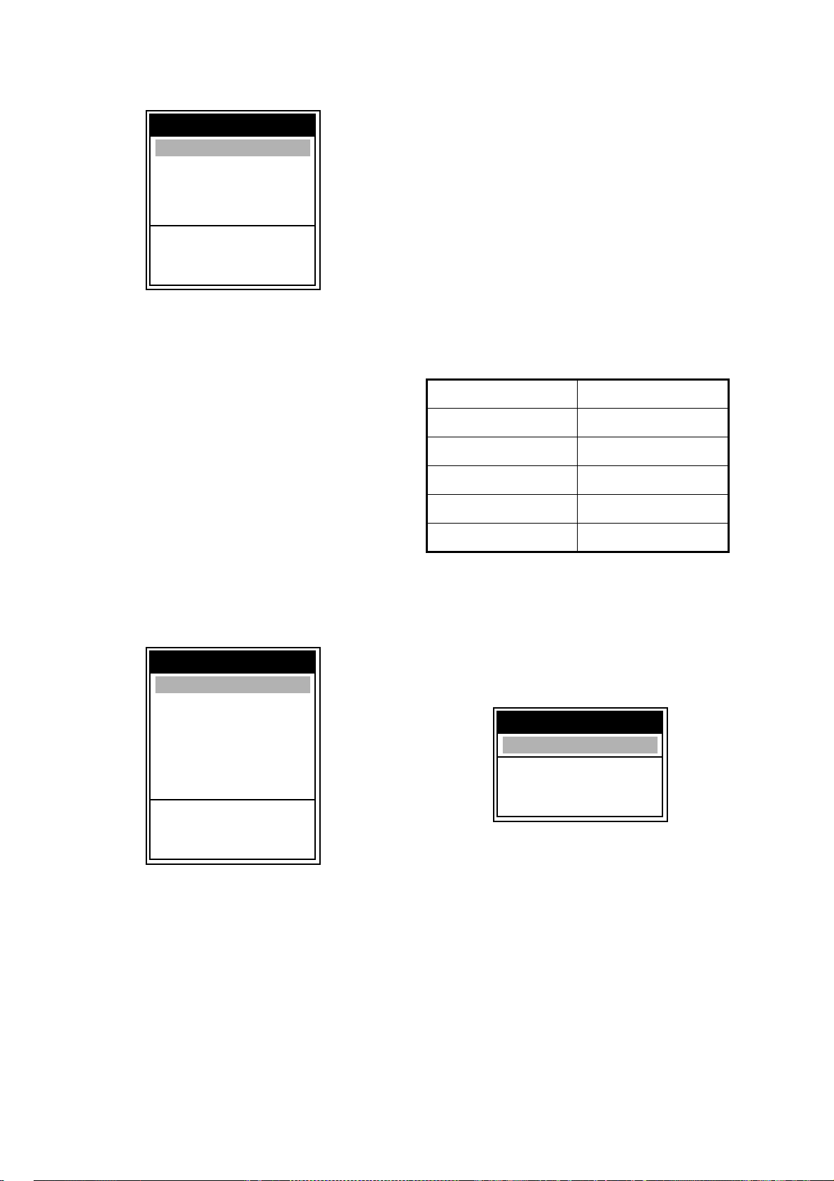
Compensation level Setting value
Double +100
1/2 -50
1/3 -65
1/4 -75
1/5 -80
Water Type: Choose the water type with
which to use the FCV-620/585, from Salt or
Fresh. Choose correct water type to get accurate depth data.
Calibration
Draft
Gain ADJ 200
Gain ADJ 50
Temp
Speed (STW) : + 0%
Fish Level
Water Type
S
/ T / W / X : Select
[ENTER] : Enter
[MENU] : Back
: + 0.0 ft
: + 0
: + 0
: + 0.0 °F
: + 0
: Salt
Calib menu
Draft: The default depth display shows the
distance from the transducer. If you would
rather show the distance from the sea surface, set your ship’s draft (setting range: -15.0
to +50.0 ft).
Gain ADJ 200, Gain ADJ 50: If the gain is too
high or too low, or the gain for the low and
high frequencies appears unbalanced, you
can compensate it (setting range: -20 to +20).
2.7 Demo Menu
Demonstrate
Demonstrate
S
/ T / W / X : Select
[ENTER] : Enter
[MENU] : Back
Demo menu
Demonstrate: The demonstration mode provides, without connection of the transducer,
simulated operation of the equipment, using
internally generated echoes. All controls are
operative. The message “DEMO” appears at
the bottom right corner on the screen when
the demonstrate mode is active.
Off: Turn demo mode off.
Demo1: Shallow depth demonstration
Demo2: Deep depth demonstration
: Off
21
Page 31
3. M AIN TENANCE, TROUB LESHOOTING
3.3 T ransducer Maintenance
Marine life on the transducer face will result in
WARNING
ELECTRICAL SHOCK HAZARD
Do not open the equipment.
Only qualified personnel
should work inside the
equipment.
3.1 Maintenance
Regular maintenance is essential for good
performance. Checking the items listed in the
table below monthly will help keep your equipment in good shape for years to come.
a gradual decrease in sensitivity. Check the
transducer face for cleanliness each time the
boat is dry-docked. Carefully remove any
marine life with a piece of wood or fine-grade
sandpaper.
3.4 Replacing the Fuse
The fuses (Type: FGBO-A 125V 2A, Code
No.: 000-155-849-10) in the power cable protect the system from reverse polarity of the
power supply and equipment fault. If a fuse
blows, find the cause before replacing it.
Using the wrong fuse will damage the unit and
void the warranty.
Checking
Item Action
Transducer
cable
Power cable,
transducer cable
plug
Display unit
ground
Power supply
voltage
Check cable for damage.
Check that they are tightly
fastened. Refasten if necessary.
Check for corrosion. Clean
if necessary.
Check voltage. If out of
rating correct problem.
3.2 Cleaning the Display
Unit
Dust or dirt on cabinets may be removed with
a soft, dry cloth. For stubborn dirt, watermoistened cloth may be used.
To clean the display screen, use soft tissue
paper. Wipe carefully to prevent scratching.
Do not use solvents such as thinner, acetone
or benzene to clean unit. They may remove
paint and markings and deform the equipment.
WARNING
Use the proper fuse.
Fuse rating is shown on the cable.
Use of a wrong fuse can result in fire and
damage the equipment.
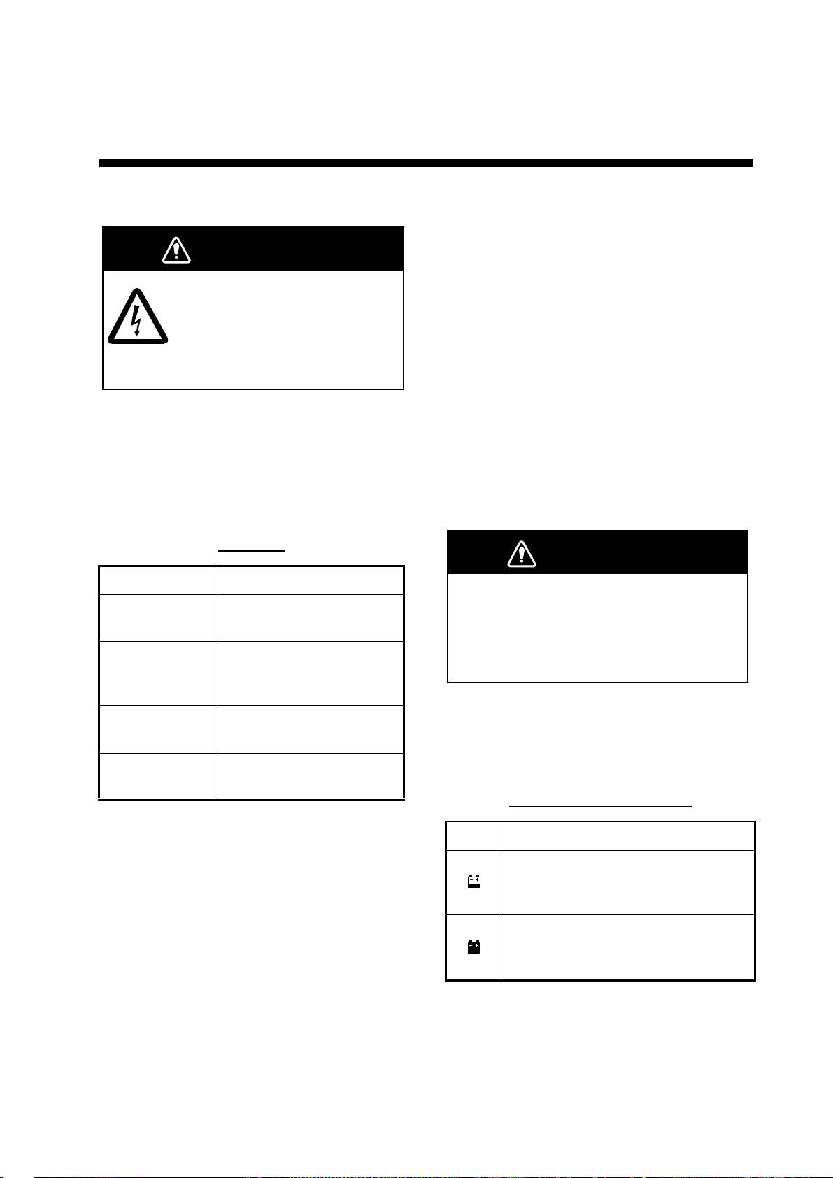
3.5 Battery Voltage Alert
A battery icon appears when the battery
voltage is too high or too low.
Battery icon and meaning
Icon Meaning
Voltage is lower than 10 VDC. If the
voltage goes below 9 V, the equipment is automatically turned off.
Voltage is higher than 32 VDC. If the
voltage goes higher than 33 V, the
equipment is automatically turned off.
22
Page 32
3. MAINTENANCE, TROUBLESHOOTING
3.6 Troubleshooting
The table below provides basic troubleshooting procedures which the user may
follow to restore normal operation.
Troubleshooting table
If... then check...
neither echo nor
fixed range scale
appears
no echo appears
but the fixed range
scale appears
echo appears but
no zero line
• battery voltage.
•fuse.
• power supply.
• power cable.
• if display advance
speed is not set to
"Stop."
• transducer plug.
• transducer cable.
• if range shifting is set
to "0."
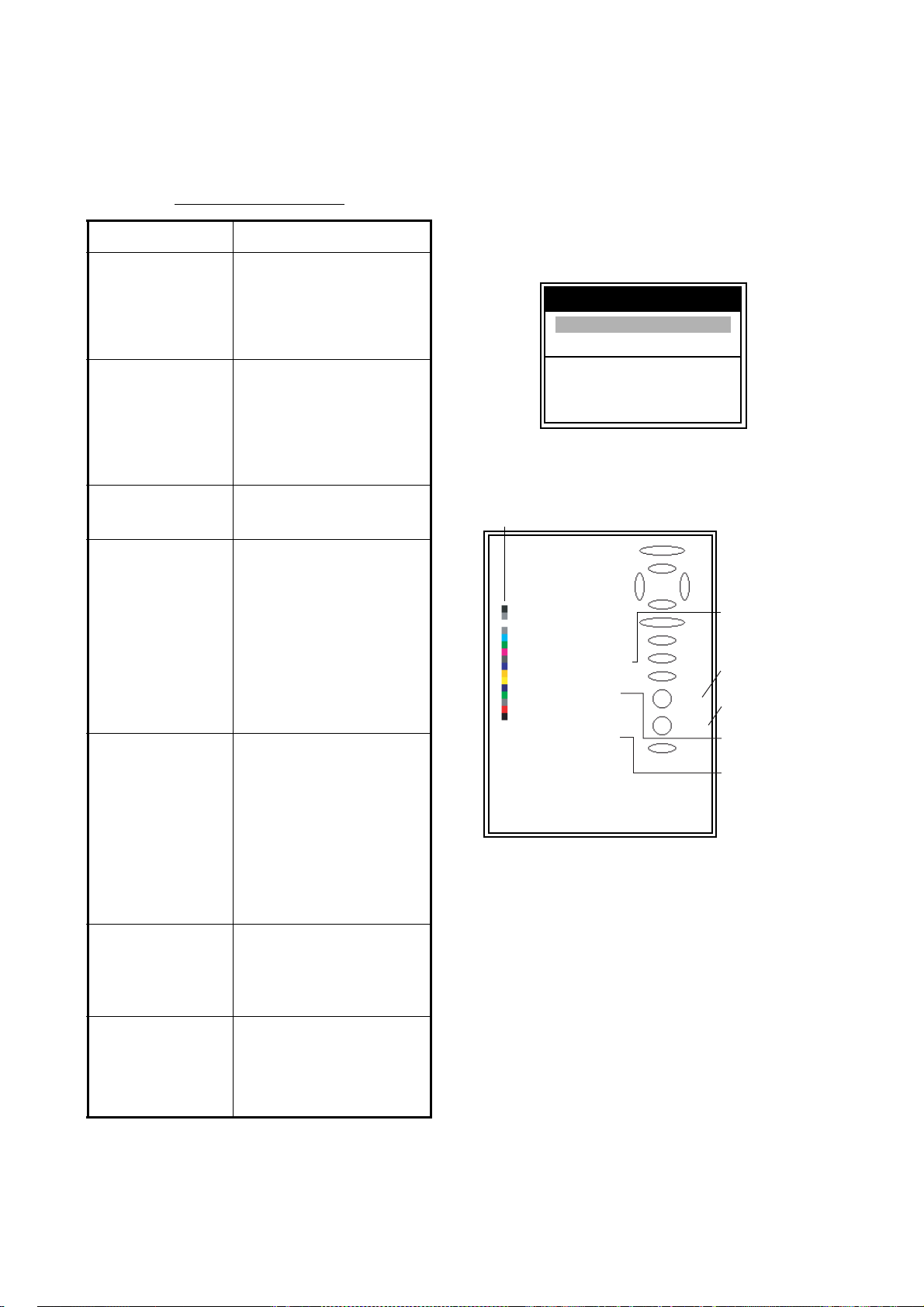
3.7 Diagnostics
If you feel your unit is not working properly,
conduct the diagnostic test to find the
problem. If you cannot restore normal operation, contact your dealer for advice.
1.
Press the MENU/ESC key to open the menu.
2. Use S or T to choose Tests under System
and press the ENTER key.
Tests
Test
LCD Test
S
/ T / W / X : Select
[ENTER] : Enter
[MENU] : Back
Tests menu
Use S or T to choose Test and press the
3.
ENTER key.
Color Bar
sensitivity is low
there is extreme
interference or
noise
the speed/water
temperature
readout is unrealistic or not present
the position
readout is unrealistic or not present
• gain setting.
• if air bubbles or marine
life is not clinging to
the transducer face.
• if sediments are not
present in the water.
• if the bottom is too soft
to return an echo.
• if the transducer is too
close to the engine.
• if the unit is properly
grounded.
• if other echo sounders
of the same frequency
as own are being operated nearby.
• sensor plug.
• the connection
between sounder and
navigator.
• navigator.
ROM : OK
SDRAM : OK
:
NMEA
°
Temp : -9.5
Speed : 10.0 kt
Power : 12.4 V
ECHO
CPU Program No. :
FPGA Program No. : 0252348-XX.XX
Push [MENU] 3 times to exit.
*: Updated every second.
XX: Program version number
**: FCV-620: 0252346-XX.XX
FCV-585: 0252347-XX.XX
F
}
: 4281
0252346-XX.XX**
5.0
DUAL
Water
temperature*,
Speed*
Indication of
GAIN knob
Indication of
MODE knob
Battery
Voltage*
For adjustment
at factory
Test display
The ROM, SDRAM and NMEA port are
checked, with the results shown as OK or
NG (No Good). For any NG, request service. (A special connector is required to
test the NMEA port. Nothing appears if no
connector is connected.)
4. The ovals and circles at the right side of the
test display are for checking the controls.
Checking key and TrackPad: Press each
key and the arrows on the TrackPad one
by one. A control's corresponding onscreen oval "lights" in red if the control is
normal.
23
Page 33
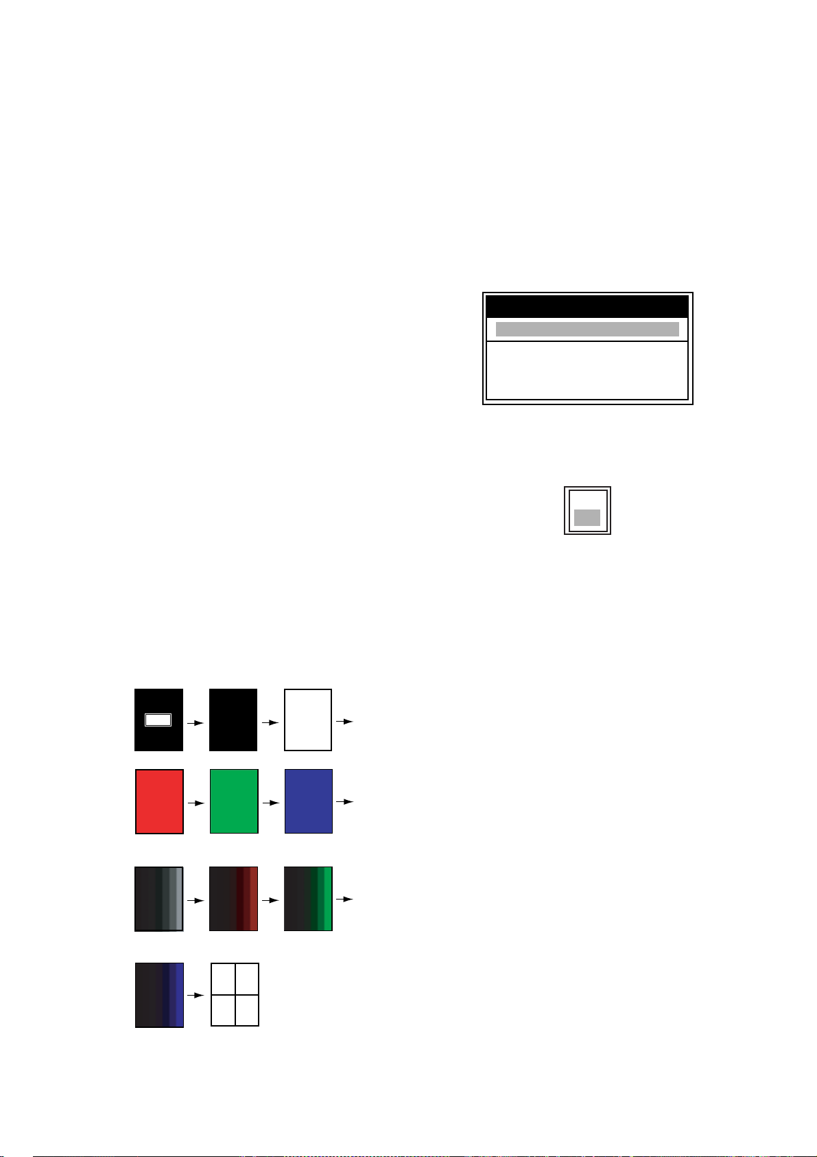
3. MAINTENANCE, TROUBLESHOOTING
Operating
d
S
S
Checking GAIN knob: Rotate the knob.
The indication goes higher with clockwise
rotation; lower with counterclockwise rotation. Press the knob. The knob corresponding on-screen circle "lights" in red if
the knob is normal.
Checking MODE knob: Rotate the knob,
and corresponding on-screen circle "lights"
in red and white alternately.
5. To return to the Tests menu, press the
MENU/ESC key three times.
6.
Press the MENU/ESC key twice to close the
window.
3.8 Test Pattern
This feature tests for proper display of LCD.
Note: To review the seven tone screen easily,
set contrast (FCV-620 only) and brilliance to
maximum before starting the test.
1. Press the MENU/ESC key to open the menu.
2. Use S or T to choose Tests under System
and press the ENTER key.
3. Use S or T to choose LCD Test and
press the ENTER key.
4. Press any key except MENU/ESC key to
start the test.
The entire screen changes as below with
each press of any key except MENU/ESC
key. After crosshatch screen, the Tests
menu appears.
escription
Black
White
5. Press the MENU/ESC key twice to close
the window.
3.9 Memory Clear
The memory can be cleared to start afresh
with default menu settings except for language setting.
1. Press the MENU/ESC key to open the menu.
2. Use S or T to choose Reset under System
and press the ENTER key.
Reset
Factory Reset
S
/ T / W / X : Select
[ENTER] : Enter
[MENU] : Back
Reset menu
3. Confirm Factory Reset is selected and
press the
4. Use
ENTER key.
After the memory is cleared, the unit beeps
and the installation menu appears (see page
2).
5. Press the MENU/ESC key twice to close
the window.
ENTER key.
Yes
No
Reset setting box
S to choose Yes and press the
[MENU] : Quit
Other Keys : Next
Red
even tone
(black)
even tone
(blue)
Green
Seven tone
(red)
Crosshatch
Seven tone
(green)
LCD test pattern
Blue
24
Page 34
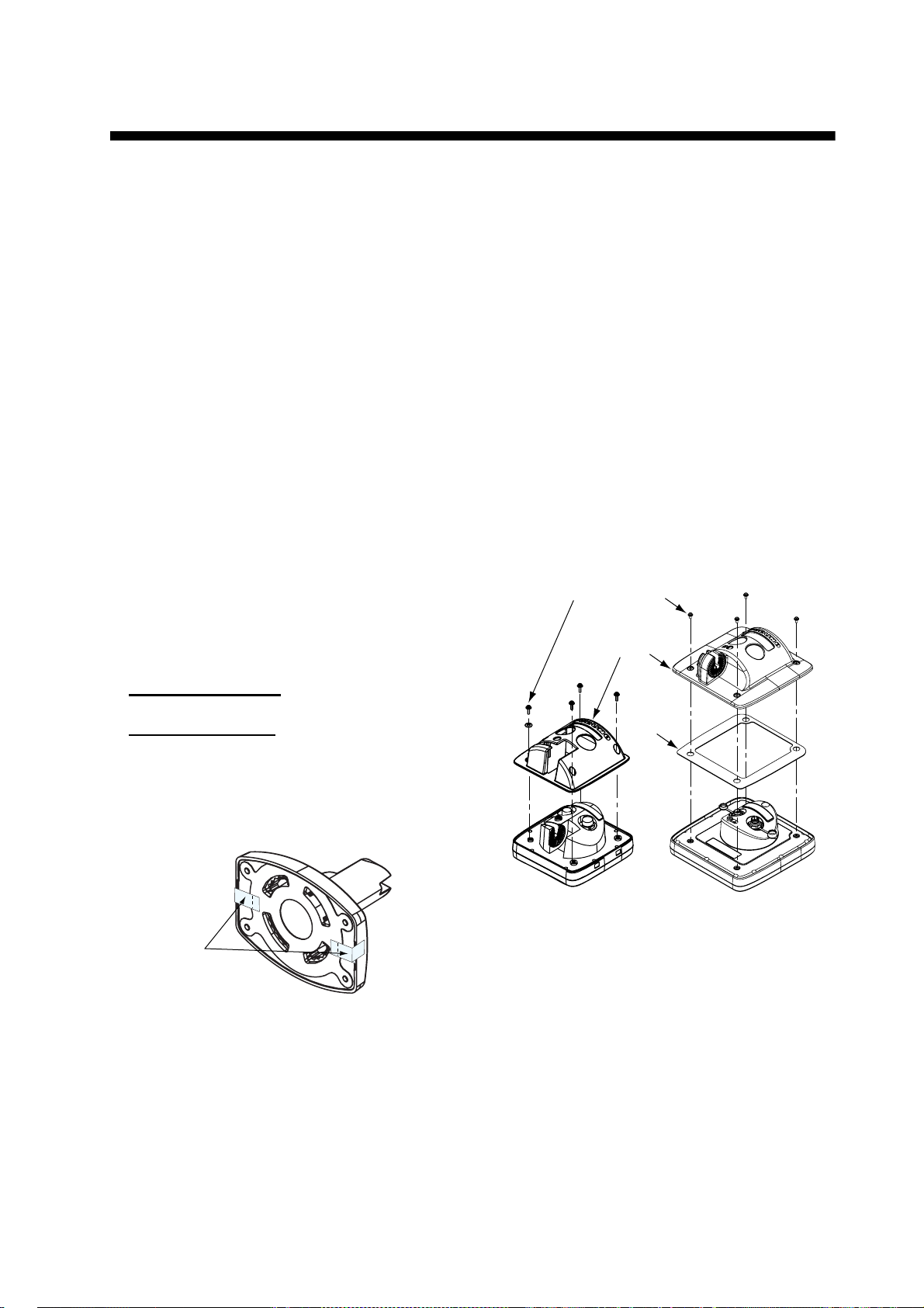
4. INSTALLATION
T
(
Washer head screw
4.1 Display Unit
Mounting considerations
The display unit can be installed on a tabletop
or flush mounted in a panel. When choosing a
location keep the following in mind:
• The temperature and humidity should be
moderate and stable.
• Locate the unit away from exhaust pipes
and vents.
• The mounting location should be well ventilated.
• Mount the unit where shock and vibration
are minimal.
• For maintenance and checking purposes,
leave sufficient space at the sides and rear
of the unit and leave slack in cables.
• A magnetic compass will be affected if the
display unit is placed too close to it.
Observe the following compass safe distances to prevent disturbance to the magnetic compass:
Standard compass
FCV-620: 0.3 m, FCV-585: 0.5 m
Steering compass
FCV-620: 0.3 m, FCV-585: 0.3 m
Note: When loosening the knob to adjust the
angle of the display, do not decline the unit
90-degree backward. The cable connector
may be damaged if it contacts the bracket.
6. Attach the hard cover to the display unit.
Flush mounting in a panel
Note: It is recommended to set up a dedi-
cated breaker when flush mounting the unit,
since it will be difficult to disconnect cables.
1. Using the paper template (supplied), make
a cutout in the mounting location.
2. Loosen four washer head screws on the
rear of the display unit to remove the
bracket cover and the cover sponge (FCV585 only).
Bracket cover
Cover
sponge
Tabletop mounting
1. Remove the tape from the bottom of the
bracket assembly.
2. Fix the bracket assembly to a tabletop with
four self-tapping screws (5x25, supplied).
3. Loosely screw knob into the bracket
assembly.
4. Set the display unit to the bracket
assembly.
5. Adjust the angle of the display unit and
then tighten the knob to fix the display unit.
ape
FCV-620 only)
Bottom of the bracket
FCV-620
How to remove the bracket cover
3. Set the flush mounting sponge (supplied)
to the display unit.
4. Screw four threaded rods (M4x50, supplied) to the display unit.
5. Set the display unit to the cutout.
6. Fasten the display unit from behind with
four sets of flat washer, spring washer and
wing nut (supplied).
FCV-585
25
Page 35
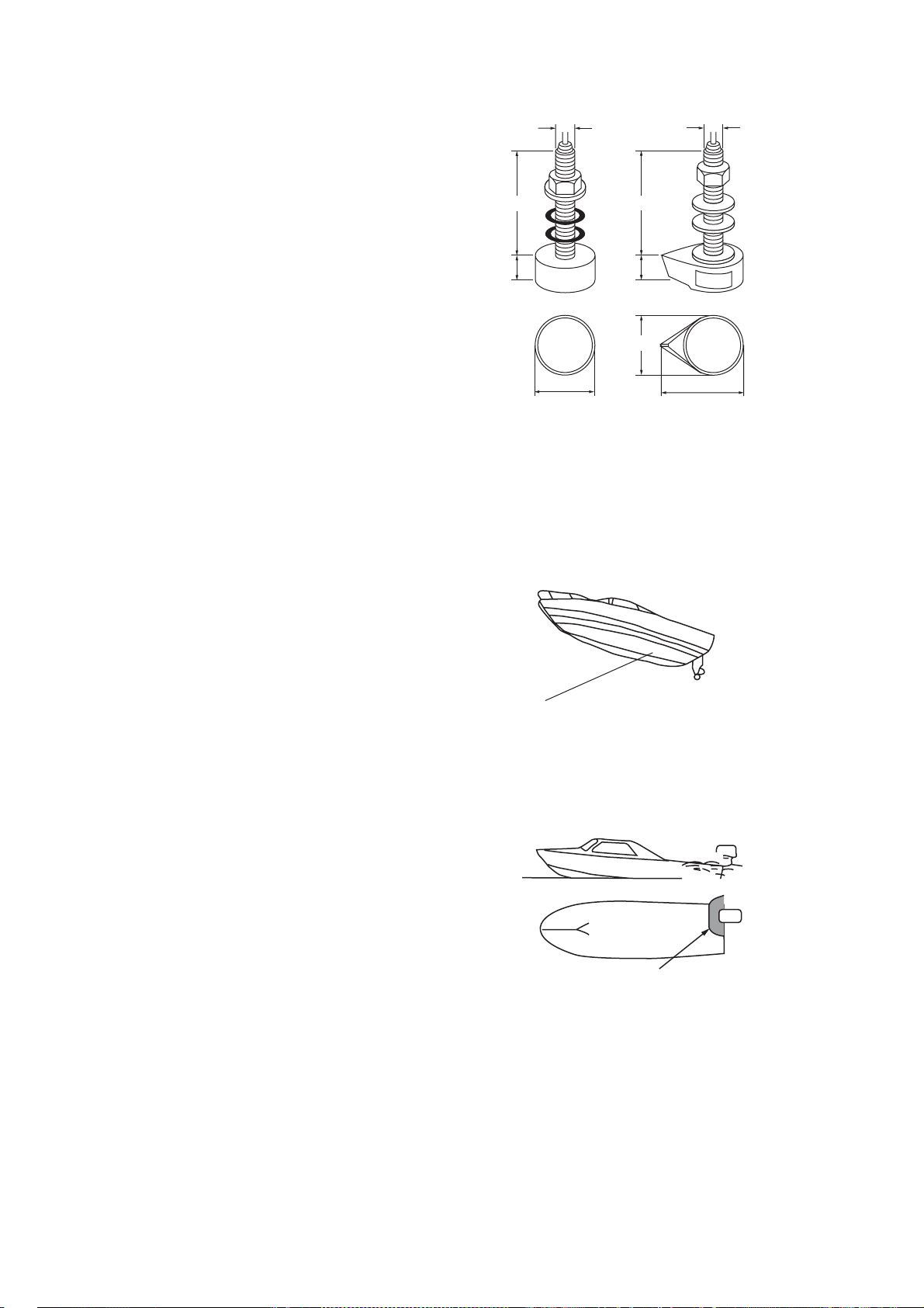
4. INSTALLATION
22
3
24
m
4.2 Thru-hull Mount Transducer
Transducer mounting location
The thru-hull mount transducer (520-5PSD,
520-5MSD) provides the best performance of
all, since the transducer protrudes from the
hull and the effect of air bubbles and turbulence near the hull skin is reduced. When the
boat has a keel, the transducer should be at
least 30 cm away from it. Typical thru-hull
mountings are shown in the figure on the next
page.
The performance of this sounder is directly
related to the mounting location of the transducer, especially for high-speed cruising. The
installation should be planned in advance,
keeping the standard cable length (8 m) and
the following factors in mind:
120
0
68
520-5PSD
120
28
Unit: m
68
87
520-5MSD
Thru-hull mount transducer mounting
dimens ions (millim et ers)
• Air bubbles and turbulence caused by
movement of the boat seriously degrade
the sounding capability of the transducer.
The transducer should, therefore, be
located in a position where water flow is the
smoothest. Noise from the propellers also
adversely affects performance and the
transducer should not be mounted nearby.
The lifting strakes are notorious for creating
acoustic noise, and these must be avoided
by keeping the transducer inboard of them.
• The transducer must always remain sub-
merged, even when the boat is rolling,
pitching or up on a plane at high speed.
• A practical choice would be somewhere
between 1/3 and 1/2 of the boat's length
from the stern. For planing hulls, a practical
location is generally rather far astern, so
that the transducer is always in water
regardless of the planing attitude.
Acceptable transducer mounting
locations
DEEP-V HULL
z
Position 1/2 to 1/3 of the hull
from stern.
z
15 to 30 cm off center line
(inside first lifting strakes.)
HIGH SPEED-V HULL
z
Within the wetted bottom area
z
Deadrise angle within 15°
Suitable transducer mounting locations
26
Page 36
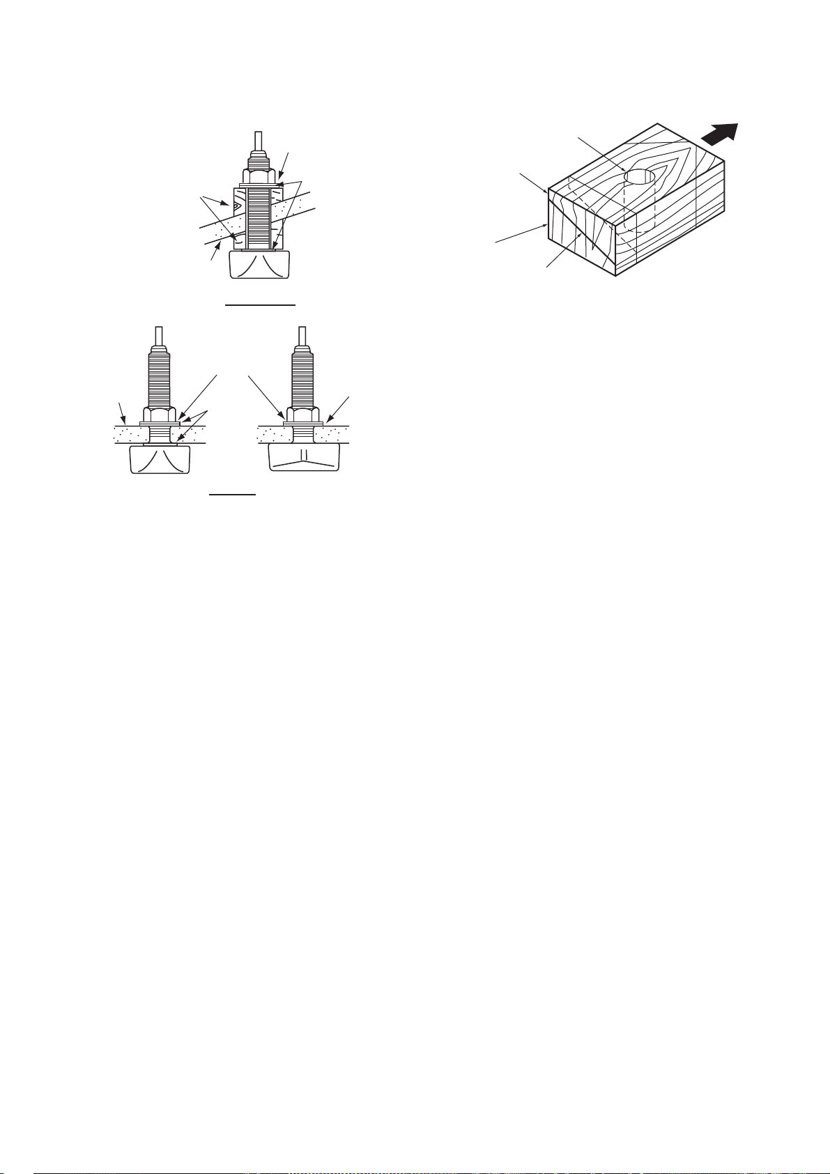
Typical thru-hull mount transducer
r
H
r
Hole for
L
4. INSTALLATION
installations
Flat Washer
Rubber Washe
Fairing
Block
Hull
Deep-V Hull
Flat Washer
ull
Rubber
Washer
Flat Hull
Cork
Washe
Typical thru-hull mount transduce r
installations
Procedure for installing the thru-hull
mount transducer
1. With the boat hauled out of the water, mark
the location chosen for mounting the transducer on the bottom of the hull.
2. If the hull is not level within 15
direction, fairing blocks made out of teak
should be used between the transducer
and hull, both inside and outside, to keep
the transducer face parallel with the water
line. Fabricate the fairing block as shown
below and make the entire surface as
smooth as possible to provide an undisturbed flow of water around the transducer.
The fairing block should be smaller than
the transducer itself to provide a channel to
divert turbulent water around the sides of
the transducer rather than over its face.
° in any
stuffing tube
Upper Half
ower Half
Saw along slope
of hull.
BOW
Construc t ion of fairing block
3. Drill a hole just large enough to pass the
threaded stuffing tube of the transducer
through the hull, making sure it is drilled
vertically.
4. Apply a sufficient amount of high quality
caulking compound to the top surface of
the transducer, around the threads of the
stuffing tube and inside the mounting hole
(and fairing blocks if used) to ensure watertight mounting.
5. Mount the transducer and fairing blocks
and tighten the locking nuts. Be sure that
the transducer is properly oriented and its
working face is parallel to the waterline.
Note: Do not over-stress the stuffing tube and
locking nuts through excessive tightening,
since the wood block will swell when the boat
is placed in the water. It is suggested that the
nut be tightened lightly at installation and
retightened several days after the boat has
been launched.
Transducer preparation
Before putting the boat in water, wipe the face
of the transducer thoroughly with a detergent
liquid soap. This will lessen the time necessary for the transducer to have good contact
with the water. Otherwise the time required for
complete "saturation" will be lengthened and
performance will be reduced.
DO NOT paint the transducer. Performance
will be affected.
27
Page 37
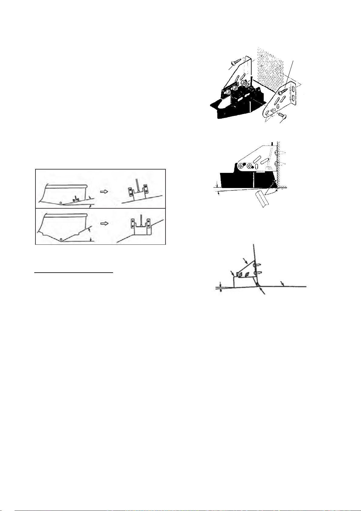
4. INSTALLATION
l
.
T
2
4.3 Transom Mount Transducer
The transom mount transducer is very commonly employed, usually on relatively small I/
O or outboard boats. Do not use this method
on an inboard motor boat because turbulence
is created by the propeller ahead of the transducer.
DO NOT overtighten screws. They may be
damaged.
525-5PWD
Choose the installation method depending on
the rise angle of the hull.
Parallel with hul
Transom
less than 10°
Mount at the stripe
Transom
Stripe
over 10°
5x20
5x20
M5x14
No.1
5°
Tape
Transom mount transducer, mounting flush
with hull
525-5PWD m ounting lo c at ions
Installing the 525-5PWD
A suitable mounting location is at least 50 cm
away from the engine and where the water
flow is smooth.
1. Drill four pilot holes for self-tapping screw
(5x20) in the mounting location.
2. Attach the transducer to the mounting loca-
tion with self-tapping screws.
3. Adjust the transducer position so the trans-
ducer faces right to the bottom.
If necessary, to improve water flow and
minimize air bubbles staying on the transducer face, incline the transducer about 5
at the rear. This may require a certain
amount of experimentation for fine tuning
at high cruising speeds.
4. Fill the gap between the wedge front of the
transducer and transom with epoxy material to eliminate any air spaces.
Bracket
ransducer
Hull
to 5°
Epoxy material
525-5PWD, mounting
4.4 Inside-hull Transducer
The thru-hull mount transducer (520-5PSD,
520-5MSD) may also be installed inside the
hull, following the procedure below.
°
Necessary tools
You will need the following tools:
• Sandpaper (#100)
• Silicone sealant
• Silicone grease
28
Page 38
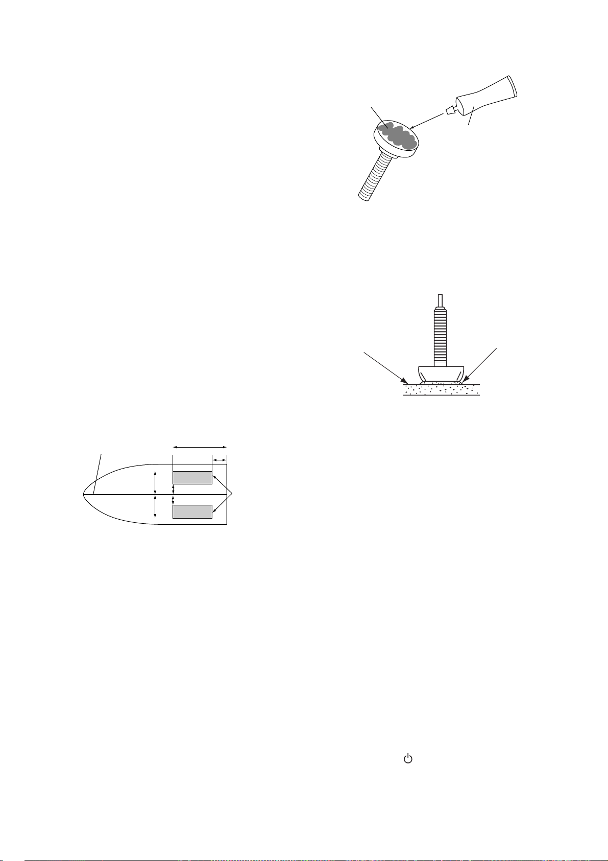
Remarks on installation
1/2
er
H
e
nt
• Turn off the engine and anchor the boat
while installing the equipment.
• Install the transducer in the engine room.
• Except for installing the transducer to the
bottom of hull, do not turn on its power so it
may be damaged.
Choosing the mounting location
4. INSTALLATION
Transducer
Silicone
Sealant
• The mounting location should be where the
hull is of single-hull thickness and is void of
air or flotation materials other than solid
fiberglass between the transducer face and
the water.
• The mounting location is between 15 to 50
cm from the centerline of the hull.
• Do not place the transducer over hull struts
or ribs which run under the hull.
• Avoid a location where the rising angle of
the hull exceeds 15
°, to minimize the effect
of the boat's rolling.
• You will finalize the mounting location
through some trial and error. The procedure for this is shown later.
Centerline
1/3
50 cm
50 cm
15 cm
15 cm
Transduc
mounting
location
Inside-hull transducer mounting location
Attaching the transducer
1. Clean the transducer face to remove any
foreign material. Lightly roughen the transducer face with #100 sandpaper. Also,
roughen the inside of the hull where the
transducer is to be mounted.
2. Clean the transducer face again to remove
scourings.
3. Warm the silicone sealant to 40
usage to soften it. Coat the transducer face
and mounting location with silicone
sealant.
°C before
Coating transducer face with silicone sealant
4. Press the transducer firmly down on the
hull and gently twist it back and forth to
remove any air which may be trapped in
the silicone sealant.
Silicon
ull
Seala
Checking the installation
1. Connect the battery to the display unit.
2. Turn on the display unit.
3. Rotate the MODE knob to choose single
frequency (LF: 50 kHz or HF: 200 kHz).
4. Press the GAIN knob to open the Auto
Gain setting window.
5. Press the GAIN knob to choose Off and
press the
6. Rotate the GAIN knob to set the gain to "5".
7. Press the RANGE key to open the Range
setting window.
8. Use X to choose Manual.
9. Press the RANGE key continuously to set
the range to 10 meters (feet) and press the
ENTER key.
10.If the bottom is displayed in reddish brown
and the depth indication appears, the
mounting location is suitable. Go to "Final
preparation."
11.If the bottom is not displayed in reddish
brown, the mounting location may be
unsuitable. Do the following:
ENTER key.
a)Press the /BRILL key to turn off the
29
power.
Page 39
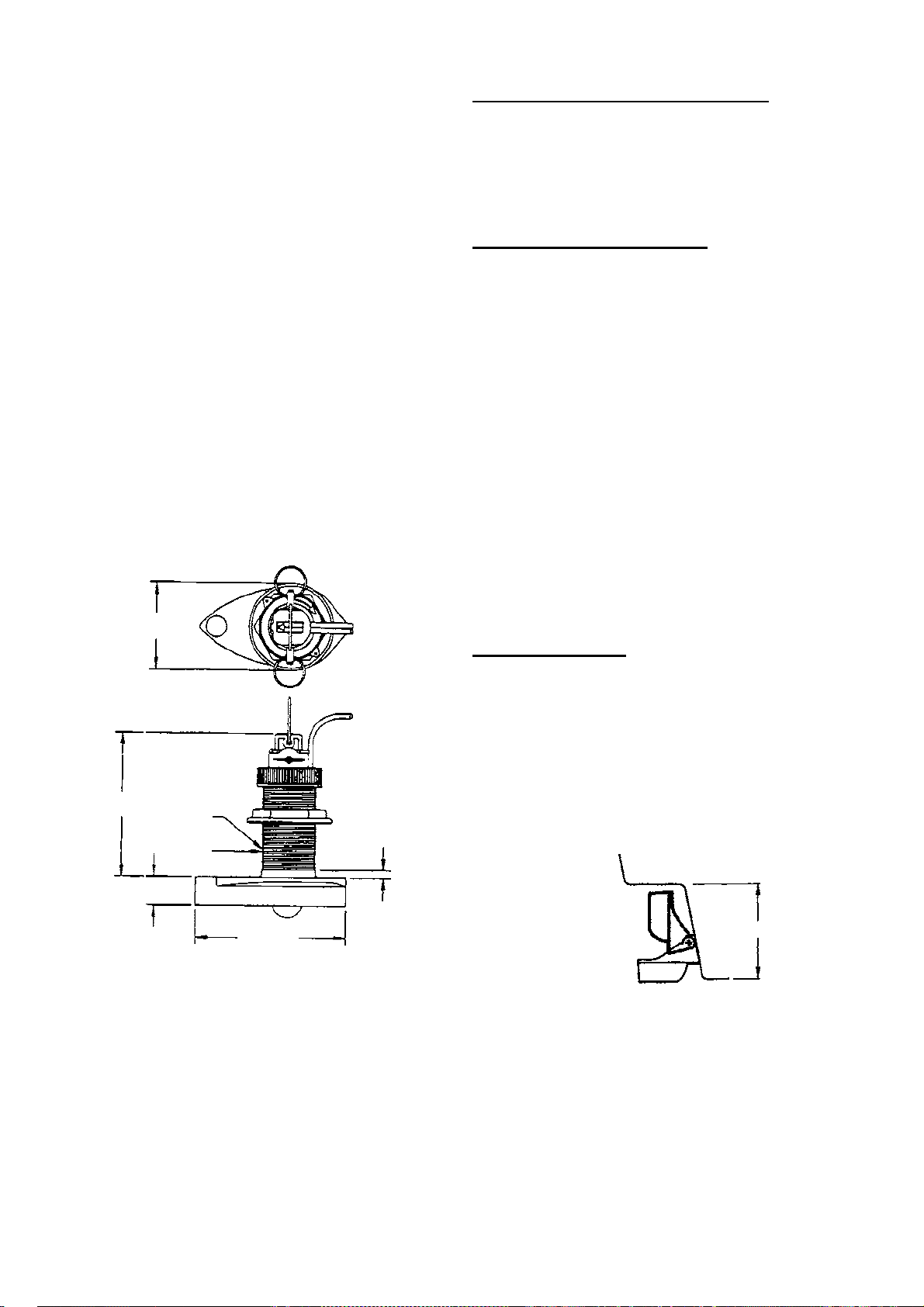
4. INSTALLATION
1
m
ht
H
s
1
H
s
2
b)Gently dismount the transducer with a
knife or a piece of wood.
c)Reattach the transducer elsewhere as
shown in "Attaching the transducer."
d)Check the installation again.
Final preparation
Support the transducer with a piece of wood
to keep it in place while it is drying. Let the
transducer dry 24-72 hours.
4.5 Triducer
DO NOT overtighten screws. They may be
damaged.
525ST-MSD
The triducer 525ST-MSD is designed for thruhull mounting. For how to install this triducer
see paragraph 4.2.
φ79 mm
Pre-test f or speed and temperature
Connect the sensor to the instrument and spin
the paddlewheel. Check for a speed reading
and the approximate air temperature. If there
is no reading, return the sensor to your place
of purchase.
Tools and materials needed
Scissors
Masking tape
Safety goggles
Dust mask
Electric drill
Drill bit for:
Bracket holes: 4mm, #23, or 9/64"
Fiberglass hull: chamfer bit (preferred),
6mm, or 1/4"
Transom hole: 19mm or 3/4" (optional)
Cable clamp holes: 3mm or 1/8"
Screwdrivers
Straight edge
Marine sealant
Pencil
Zip-ties
Water-based antifouling paint (mandatory in
salt water).
Mounting location
To ensure the best performance, the sensor
must be submerged in aeration-free and turbulence-free water. Mount the sensor close to
the centerline of the boat. On slower heavier
displacement hulls, positioning it farther from
the centerline is acceptable.
33 mm
2.00"-12 UN
threads
27 mm
φ51 mm
140 mm
7 mm
Unit: m
Allow adequate space above the bracket for it
to release and rotate the sensor upward.
eight without
peed sensor
91mm (7-1/2")
eight with
peed sensor
13mm (8-1/2")
Heig
Triducer 525ST-MSD
Height req uired at mounting locat ion
525ST-PWD
The transom mount triducer with integral
release bracket 525ST-PWD is manufactured
by AIRMAR Co. These instructions are also
included with the sensor.
Note 1 : Do not mount the sensor in an area of
turbulence or bubbles: near water intake or
discharge openings; behind strakes, struts,
fittings, or hull irregularities; behind eroding
paint (an indication of turbulence).
Note 2: Avoid mounting the sensor where the
boat may be supported during trailering,
launching, hauling, and storage.
30
Page 40
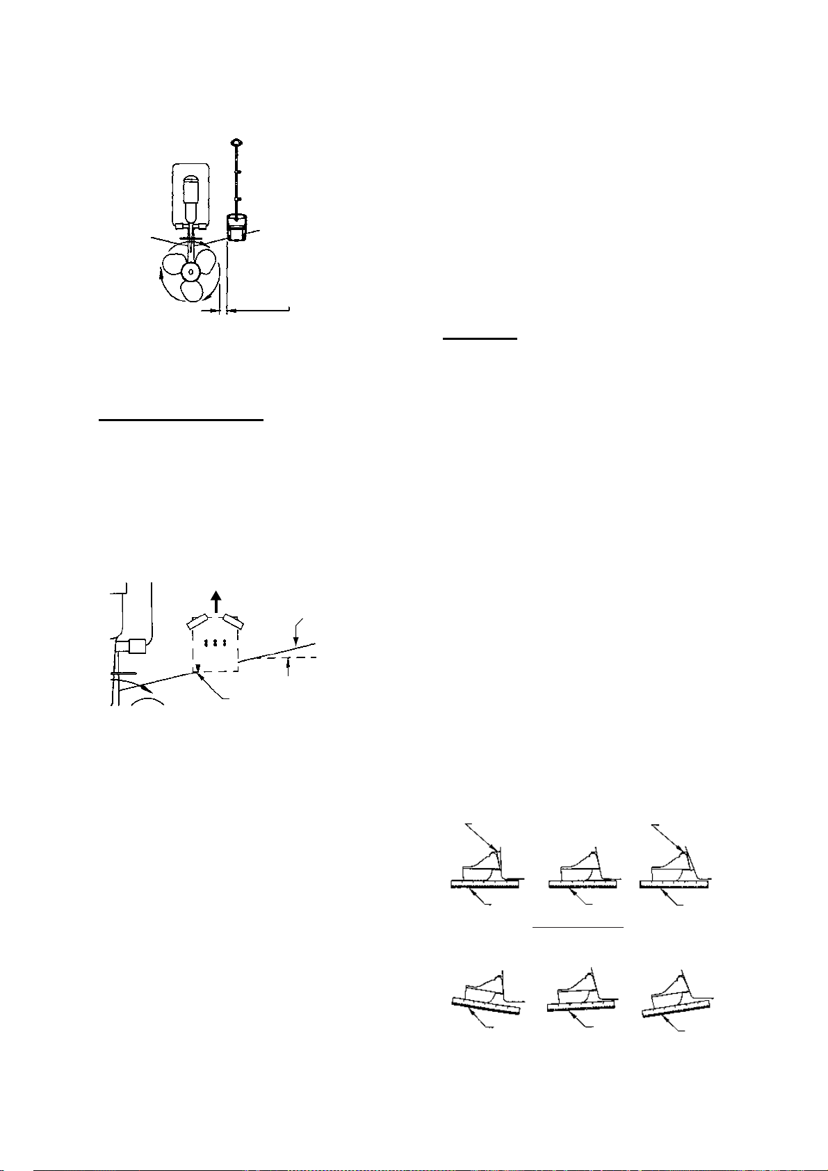
4. INSTALLATION
d
Align template vertically.
le
ll
p
Note 3: For single dri ve boa t, mount on the
starboard side at least 75 mm (3") beyond the
swing radius of the propeller.
75 mm (3")
minimum beyon
swing radius
Mounting loc at ion on single drive bo at
Note 4: For twin drive boat, mount between
the drives.
Installation of bracket
1. Cut out the installation template (enclosed
with transducer) along the dotted line.
2. At the selected location, position the template, so the arrow at the bottom is aligned
with the bottom edge of the transom. Being
sure the template is parallel to the waterline, tape it in place.
Deadrise ang
Slope of hu
parallel to
waterline
Align template arrow with
bottom edge of transom.
Positioning the template
Warning: Always wear safety goggles and a
dust mask.
Other angles: The shim is required. Skip to
step 2 of "Adjusting".
If you do not know the transom angle, temporarily attach the bracket and sensor to
the transom to determine if the plastic shim
is needed.
5. Using the three #10 x 1-1/4" self-tapping
screws, temporarily screw the bracket to
the hull. DO NOT tighten the screws completely at this time. Follow the step 1-4 in
"Attaching the sensor to the bracket",
before proceeding with "Adjusting".
Adjusting
1. Using a straight edge, sight the underside
of the sensor relative to the underside of
the hull. The stern of the sensor should be
1-3 mm (1/16-1/8") below the bow of the
sensor or parallel to the bottom of the hull.
Note: Do not position the bow of the sensor
lower than the stern because aeration will
occur.
2. To adjust the sensor's angle relative to the
hull, use the tapered plastic shim provided.
If the bracket has been temporarily fastened to the transom, remove it. Key the
shim in place on the back of the bracket.
2
°-10° transom angle (stepped transom
and jet boats): Position the shim with the
tapered end down.
19
°-22° transom angle (small aluminum
and fiberglass boats): Position the shim
with the tapered end up.
2°-10°
transom
angle
11° transom angle
NO SHIM
19°-22°
transom
angle
3. Using a 4 mm, #23, or 9/64" bit, drill three
holes 22 mm (7/8") deep at the locations
indicated. To prevent drilling too deeply,
wrap masking tape around the bit 22 mm
(7/8") from the point.
Fiberglass hull: Minimize surface
cracking by chamfering the gelcoat. If a
chamfer bit or countersink bit is not available, start drilling with a 6mm or 1/4" bit to
a depth of 1 mm (1/16").
4. If you know your transom angle, the
bracket is designed for a standard 13
transom angle.
11
°-18° angle: No shim is required. Skip to
step 3 in "Adjusting".
shim with
taper down
YES
parallel
12°-18° transom angle
NO
°
angle
reversed
YES
parallel
NO SHIM
YES
slight
angle
shim with
taper up
YES
parallel
NO
angle
too stee
Sensor pos it ion and transom angle
31
Page 41
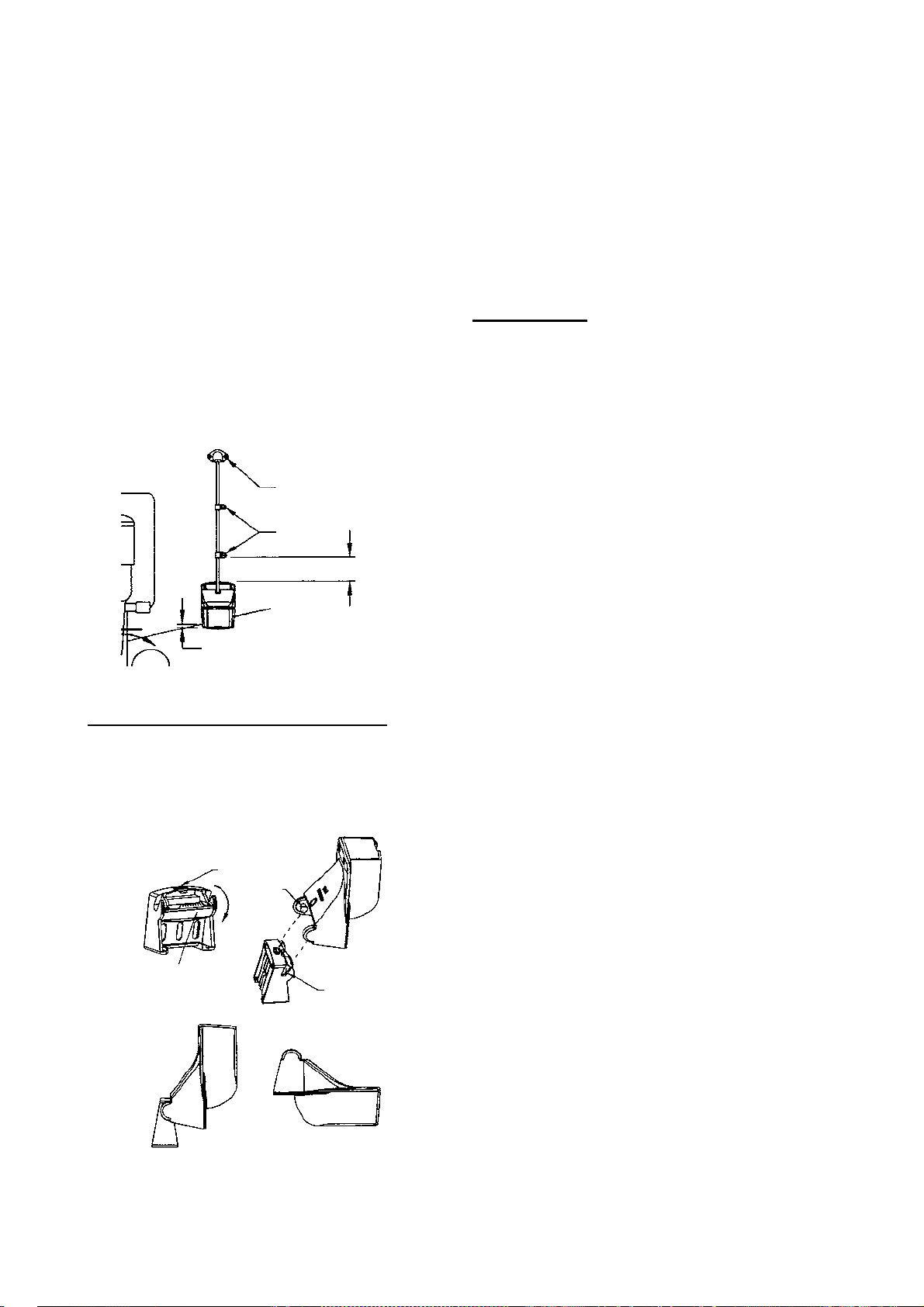
4. INSTALLATION
")
)
3. If the bracket has been temporarily fastened to the transom, remove it. Apply a
marine sealant to the threads of the three
#10 x 1-1/4" self tapping screws to prevent
water seeping into the transom. Screw the
bracket to the hull. Do not tighten the
screws completely at this time.
4. Repeat step 1 to ensure that the angle of
the sensor is correct.
Note: Do not position the sensor farther into
the water than necessary to avoid increasing
drag, spray, and water noise and reducing
boat speed.
5. Using the vertical adjustment space on the
bracket slots, slide the sensor up or down
to provide a projection of 3 mm (1/8”).
Tighten the screws.
Cable cover
Cable
clamp
50 mm (2
Hull projection 3 mm (1/8")
Vertica l adjustmen t a nd c able routin g
Attaching the sensor to the bracket
1. If the retaining cover near the top of the
bracket is closed, open it by depressing the
latch and rotating the cover downward.
Step 1
Latch
Retaining
cover
Step 3
Step 2
Pivot
arm (2)
Slot (2
Step 4
Attaching the sensor to the bracket
2. Insert the sensor's pivot arms into the slots
near the top of the bracket.
3. Maintain pressure until the pivot arms click
into place.
4. Rotate the sensor downward until the
bottom snaps into the bracket.
5. Close the retaining cover to prevent the
accidental release of the sensor when the
boat is underway.
Cable routing
Route the sensor cable over the transom,
through a drain hole, or thorough a new hole
drilled in the transom above the waterline.
Never cut the cable or remote the connector;
this will void the warranty. Always wear safety
goggles and a dust mask.
1. If a hole must be drilled, choose a location
well above the waterline. Check for
obstructions such as trim tabs, pumps, or
wiring inside the hull. Mark the location
with a pencil. Drill a hole through the transom using a 19 mm or 3/4" bit (to accommodate the connector).
2. Route the cable over or through the
transom.
3. On the outside of the hull secure the cable
against the transom using the cable
clamps. Position a cable clamp 50 mm (2")
above the bracket and mark the mounting
hole with a pencil.
4. Position the second cable clamp halfway
between the first clamp and the cable hole.
Mark this mounting hole.
5. If a hole has been drilled in the transom,
open the appropriate slot in the transom
cable cover. Position the cover over the
cable where it enters the hull. Mark the two
mounting holes.
6. At each of the marked locations, use a 3
mm or 1/8" bit to drill a hole 10 mm (3/8")
deep. The prevent drilling too deeply, wrap
masking tape around the bit 10 mm (3/8")
from the point.
7. Apply marine sealant to the threads of the
#6 x 1/2" self-tapping screw to prevent
water from seeping into the transom. If you
have drilled a hole through the transom,
apply marine sealant to the space around
the cable where it passes through the
transom.
32
Page 42
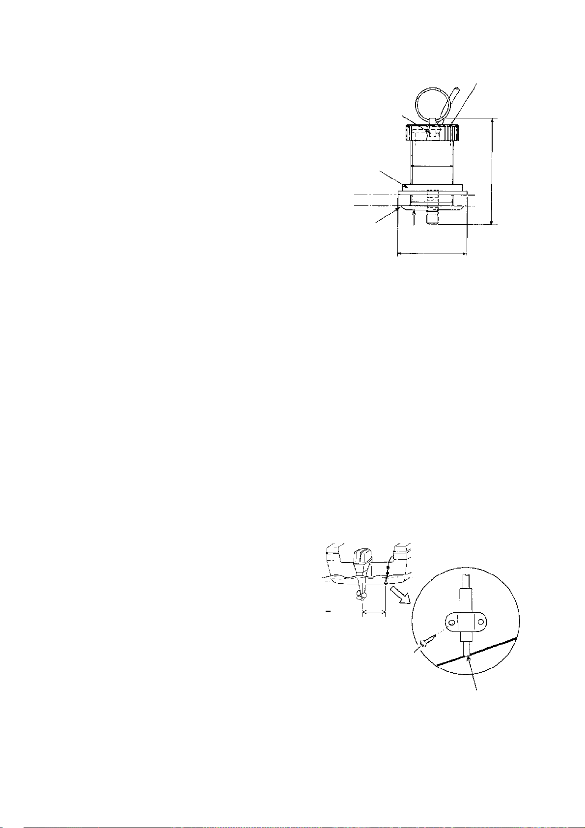
8. Position the two cable clamps and fasten
Locknut
C
s
3
them in place. If used, push the cable
cover over the cable and screw it in place.
9. Route the cable to the instrument being
careful not to tear the cable jacket when
passing it though the bulkhead(s) and
other parts of the boat. To reduce electrical
interference, separate the sensor cable
from other electrical wiring and "noise"
sources. Coil any excess cable and secure
it in place with zip-ties to prevent damage.
Face "notch"
toward bow.
Flange Nut
4. INSTALLATION
51
12
4.6 Optional Water
Temperature/Speed
Sensor
Water temperature/speed sensor ST-02MSB
and ST-02PSB, which are designed for thruhull mounting, are optionally available. Install
them as shown below.
Mounting considerations
Choose a suitable mounting location considering the following:
• Choose a place free from vibration.
• Choose a mid-boat flat position. The sensor
does not have to be installed perfectly perpendicular. The sensor must not be damaged in dry-docking operation.
• Choose a place apart from equipment gen-
erating heat.
• Choose a place in the forward direction
viewing from the drain hole, to allow for circulation of cooling water.
oat with
ilicone sealant.
Water temperature/speed sensor
ST-02M SB, ST-02PSB
Brim
φ
77
4.7 Optional Water Temperature Sensor
Transom mount water temper atur e
sensor T-02MTB
• Fix the cable at a convenient location on the
transom with the cable clamp.
• When the cable is led through the transom
board, make a hole of approx. 17 mm in
diameter to pass the connector. After
passing the cable, seal the hole with a
sealing compound.
1. Dry-dock the boat.
2. Make a hole of approx. 51 mm diameter in
the mounting location.
3. Unfasten locknut and remove the sensor
section.
4. Apply high-grade sealant to the flange of
the sensor.
5. Pass the sensor casing through the hole.
6. Face the notch on the sensor toward boat's
bow and tighten the flange.
7. Set the sensor section to the sensor casing
and tighten the locknut.
8. Launch the boat and check for water
leakage around the sensor.
33
>
D 50 cm
How to mount transom mount water
D
5x20
Flush with hull bottom.
temper at ure sensor T -02MTB
Page 43
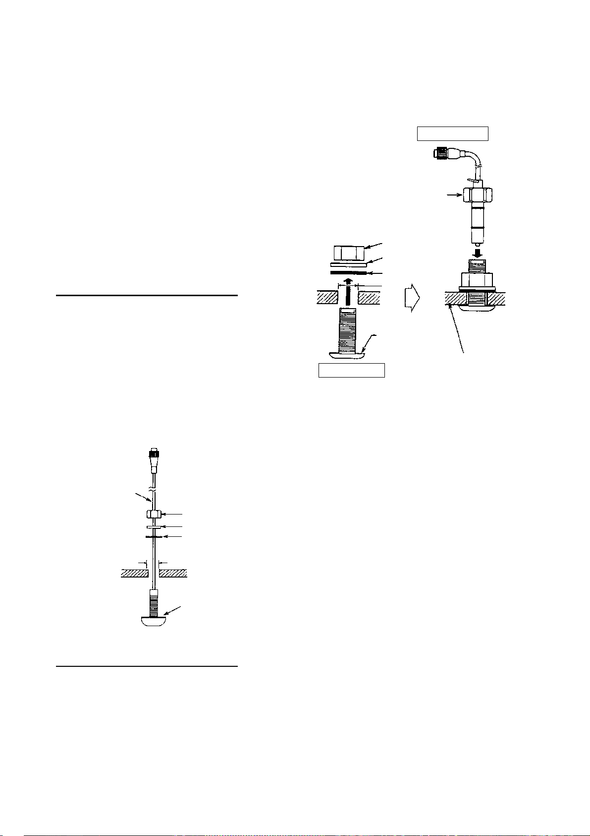
4. INSTALLATION
.
S
c
-
n
Thru-h ull mount water tem pe r at ur e
sensor T-02MSB, T-03MSB
• Select a suitable mounting location considering the following points:
• Select a mid boat flat position. The sensor
does not have to be installed perfectly perpendicular; however, the location should
not be such that the transducer may be
damaged when the boat is dry-docked.
• Locate away from equipment which gives
off heat.
• Locate away from drain pipes.
• Select a location where vibration is minimal.
Procedure for mounting T-02MSB
1. Drill a hole of 21 mm in diameter in the
mounting location.
2. Pass the sensor cable through the hole.
3. Pass gasket, washer and locknut onto
cable in that order.
4. Coat the sensor flange with high quality
sealant and then fasten the sensor with the
locknut. (Torque: max. 59N m)
5. Launch the boat to check for water leakage
around the sensor.
3. Set the sensor holder to the holder guide
from inside the boat and then tighten the
locknut.
4. Launch the boat to check for water leakage
around the sensor.
Sensor Holder
Locknut
Locknut
Washer
Gasket
φ25 mm
Coat with
sealant.
Plate thick
Holder Guide
ness withi
25 mm
Mounting T-03MSB
4.8 Wiring
Connect the power/data cable assy KON004-02M (2 m, supplied) to the 12-24 VDC/
ensor
able
Locknut
Washer
Gasket
NMEA port, and the transducer cable to the
XDR port. Refer to the interconnection diagram to connect cables. Leave slack in cables
to facilitate checking and maintenance.
Note1: Attach the MJ cable cap (supplied) to
the transducer cable to protect the connector
φ21 mm
when the display unit is removed.
Note2: Cut unused cores and tape them.
Coat with
sealant.
Note3: Connector of cable edge breaks
easily. Be careful when connecting or disconnecting the connector.
Mounting T- 02MSB
Note4: The fuse holder contains a spring
Procedure for mounting T-03MSB
1. Drill a hole of 25 mm in diameter in the
mounting location.
which fixes the fuse. To prevent detachment
of the spring, which would cause loss of
power, tie the line as shown on the next page.
2. Coat holder guide with high quality sealant,
and pass gasket, washer and locknut onto
holder guide in that order and then tighten
the locknut.
34
Page 44
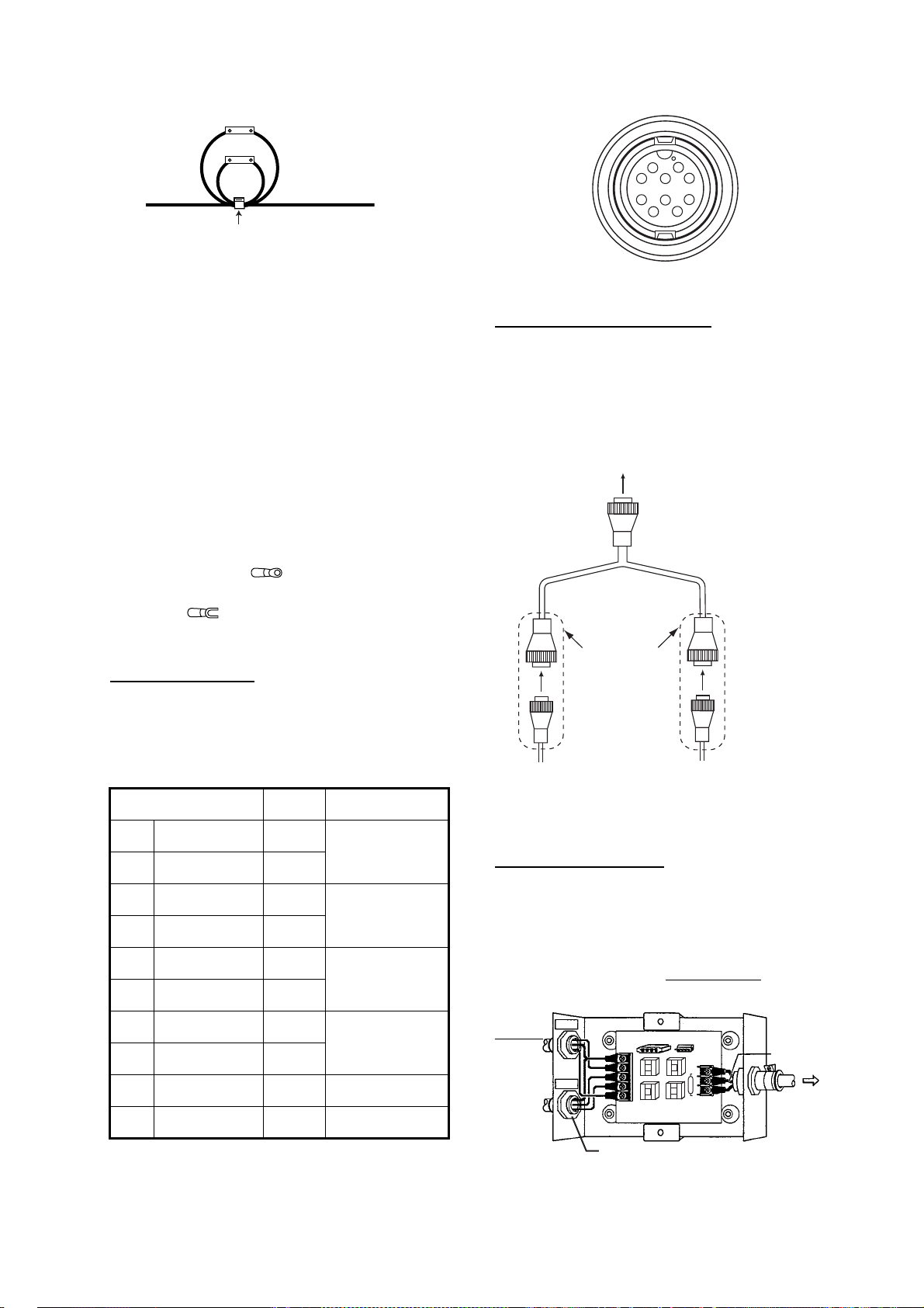
4. INSTALLATION
s
Fuse holder
Power supply line
(red and black)
Cable tie
How to fix fuse holders
Establishing the ground
The ground wire (1.25 sq or more, local
supply) should be as short as possible. The
signal line ground is isolated from the chassis
ground, however the power line is not insulated. Therefore, when connecting eternal
equipment having positive ground, do not
ground the signal line to the chassis. If excessive noise shows on the screen, the ground
may be inadequate. In this case, attach a
steel plate measuring 20 cm by 30 cm on the
outside of the hull to provide a ground point.
Connect the ground wire there. Use a
"closed" type lug ( ) to make the connection at the display unit. Do not use an "open"
type lug ( ).
1
8
7
6
2
9
3
10
4
5
Pin assignment (front view)
Water temp/speed sensor
Connect the optional water temp/speed
sensor to the XDR port with the optional conversion cable (Type 02S4147) as shown
below.
Connect to XDR port
at rear of display unit
MJ-A10SPF
MJ-A6SRMD
MJ-A10SRMD
Optional equipment
Power connector
The power supply port is commonly used for
connection of external equipment such as a
GPS receiver or wind indicator. Refer to the
interconnection diagram to connect cables.
10 SHIELD -
Connector Color Remarks
1TD-A WHT
2TD-B BLU
3 RD-A YEL
4RD-B GRN
5 TEMP-IN BRN
6TEMP-IN-0V ORG
7 DC-P-IN RED
8 DC-N-IN BLK
IEC61162-1/
NMEA0183
IEC61162-1/
NMEA0183
Temperature
analog input
Power input
12-24 VDC
9NC -
Tape connectors with
vulcanizing tape
and then vinyl tape
to waterproof them.
Bind tape ends with
cable ties to prevent
From
sensor
tape from unraveling.
From
transducer
Connection of conversion cable 02S4147
Optional transducer
The optional matching box (Type: MB-1100,
Code No.: 000-041-353) is required to connect the optional transducers 50B-6, 50B-6B,
200B-5S, 50/200-1T.
Jumper block setting
J2: No output reduction (default)
J1: Output reduction
ransducer
50B-6/6B
00B-5S
50kHz
200kHz
TB2
SHIELD
1
BLK
2
RED
3
BLK
4
RED
5
Detach grommet;
attach cord lock.
J2 J1
02P6348
TB1
3
2
1
BLK
WHT
Green
(shield)
Connect 10P
connector to
XDR port on
rear of
display unit.
Matching box MB-1100, cover removed
35
Page 45
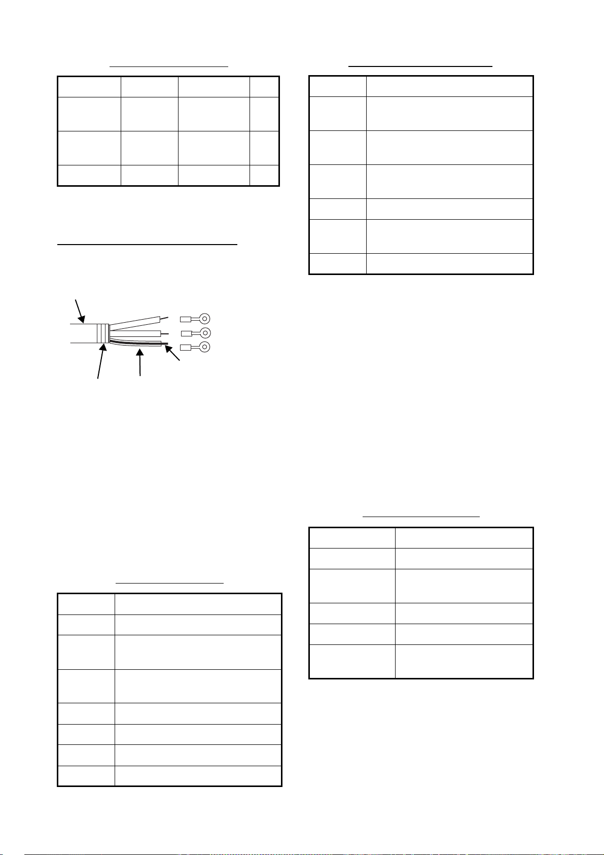
4. INSTALLATION
g
Matching box MB-1100
Part Type Code No. Qty
Matching
Box*
Crimp-on
Lug
Cord Lock** NC-1 000-516-650 1
MB-1100 000-041-000 1
FV1.25-3,
red
000-538-113 6
*: With 10P connector cable
**: For connecting two transducers
Fabricating the transducer cable
Fabricate the transducer cable as below and
connect it to the matching box.
Vinyl Sheath
Crimp-on Lug
FV1.25-3, Red
Shield
Taping
Shrink T ubin
How to fabricate the transducer cable
4.9 IEC 61162-1 Data
Sentences
Input data sentences (con’t)
MWV Wind speed and angle.
RMA Recommended minimum specific
LORAN-C data.
RMB Recommended minimum naviga-
tion information.
RMC Recommended minimum specific
GPS/TRANSIT data.
VHW Water speed and heading.
VTG Course over ground and ground
speed.
XTE Cross track error.
Order of priority
Latitude/Longitude: GGA>RMC>RMA>GLL
Course (true): VTG>RMC>RMA
Course (magnetic): VTG
Ground speed: VTG>RMC>RMA
Water speed: VHW
Distance to waypoint: BWC>RMB
Bearing to waypoint (true): BWC>RMB
Bearing to waypoint (magnetic): BWC
Heading (true): HDT>VHW
Heading (magnetic): HDG>VHW
Cross track error: XTE>RMB
Atmospheric pressure: MDA
Water temperature: MTW
Wind speed and angle (true/apparent): MWV
The table below shows the data sentences
which can be input to and output from the
FCV-620/585. The transmission speed for
both input and output is 4,800 bps. Data is
transducer cableoutput at two-second intervals.
Input data sentences
Sentence Meaning
BWC Bearing and distance to waypoint.
GGA Global positioning system (GPS)
fix data.
GLL Geographic position - latitude/lon-
gitude.
HDG Heading, deviation and variation.
HDT Heading, true.
MDA Atmospheric pressure.
MTW Water temperature.
Output data sentences
Sentence Meaning
DBT (Ver. 1.5) Depth below transducer
DPT (Ver. 2.0,
Ver. 3.0)
MTW* Water temperature
VHW* Water speed and heading
TLL* Target position, output by
Depth
MARK key.
*= Available with connection of optional sensors/navaid
36
Page 46

4. INSTALLATION
4.10 Adjustments after
Installation
NMEA
1. Press the MENU/ESC key to open the
menu.
Use S or T to choose NMEA under System
2.
menu and press the ENTER key.
NMEA
NMEA0183 : Ver 2.0
NMEA Port
NMEA Output : Off
WAAS Setup
TLL Output
S
[ENTER] : Enter
[MENU] : Back
NMEA0183
/ T / W / X : Select
NMEA menu
: In/Out
: Off
: TLL
WAAS Setup
Choose how to use the WAAS signal when
connecting with a WAAS receiver, for
example GP-320B. The message types
(WAAS-00 to WAAS-27) are used as WAAS
correction. Choose WAAS-00 to enable
WAAS.
Note: Currently, WAAS is only available in
North America, and it is in the developmental
stage in Europe and Japan. During the developmental phase the reliability and availability
of the WAAS signal cannot be guaranteed.
Therefore, any position data should be verified against other sources to confirm reliability. This function is available only when In/
Out is selected at NMEA Port.
TLL Output
Output the position specified by MARK key to
the plotter connected.
Choose NMEA0183 version of nav equipment
connected to “12-24 VDC/NMEA” port among
Ver 1.5, Ver 2.0 or Ver 3.0.
NMEA Port
The NMEA terminals in the “12-24 VDC/
NMEA” port can function as input ports or
input/output port. Change the setting to "In/In"
when connecting GP-310B/320B and a wind
sensor.
When connecting the GP-320B and a wind
sensor, first turn on "WAAS Setup" and then
select "In/In" as the NMEA Port setting.
In/Out: Input and Output (default setting)
In/In: Input only (Available with connection of
the GP-310B/320B and a wind sensor.)
NMEA Output
Set the output data sentences (see the lefttable).
Off: Does not output latitude/longitude.
TLL: Outputs latitude/longitude.
FURUNO-TLL: Outputs latitude/longitude,
depth and water temperature. Required
FURUNO-TLL enabled device.
Transducer (FCV-585 only)
Choose transducer type among 600 W, 1 kW
and 50/200-1T on the Sounder menu.
600W
1kW
50/200-1T
Transducer setting box
600 W: For 600 W transducer
50/200-1T: For 1 kW transducer (50B-6, 50B-
6B, 200B-5S or 50/200-1T)
1 kW: For 1 kW transducer other than those
mentioned above
Off: Outputs the “output data sentences” of
FCV-620/585 only.
On: Outputs the “output data sentences” of
FCV-620/585 and sentences which are input
from other equipment.
37
Page 47
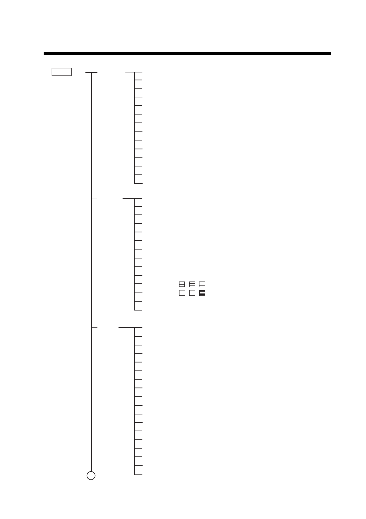
MENU TREE
MENU key
Sounder
Pic. Advance (4/1, 2/1,
Zoom Mode (
Shift (0 - 2500 ft,
Bottom Area
Interference (Off, Low, Medium, High,
Color Erase (0 - 50 %,
Clutter (0 - 100 %,
White Line (0 - 50 %,
White Marker
TVG (Low,
Smoothing (Off,
TX Power (
TX Rate (1 Transducer (
Bottom Lock
Medium
Auto
10
, S)
600 W
1/1
, 1/2, 1/4, 1/8, 1/16, Stop)
, Bottom Zoom, Marker Zoom)
0 ft
)
0 %
)
0 %
)
0 %
)
, High)
On
)
, 10 - 100 %)
, 1 kW, 50/200-1T)
Auto
Bold: Default
)
Display
Alarm Bottom (
1
Off
A-Scope (
Depth Size (Small, Medium,
Zoom Marker (
Temp Graph (
Window Size
Battery (
Color Bar (Off,
Palette (
Colors (8, 16,
Header Info (Off,
Nav Data1 ( , , )
Nav Data2 ( , , )
Fish Info (
Fish Symbols (
From (0 - 2500 ft,
Span (1 - 2500 ft,
Fish (Normal) (
From (0 - 2500 ft,
Span (1 - 2500 ft,
Fish (B/L) (
From (0.0 - 30.0 ft,
Span (0.1 - 30.0 ft,
Fish Level (Weak,
Temperature (
From (20.0 - 110.0 °F,
Span (0.1 - 30.0 °F,
Speed (
From (0.0 - 99.0 kt,
Span (1.0 - 50.0 kt,
Arrival (
Radius (0.01 - 99.99 nm,
, Normal, Peak)
Off
, On)
Off
, Narrow, Wide)
Off
, On)
On
)
White
, Blue, Black, Gray, Night)
64
)
On
)
Off
, Level, Depth)
Off
, Solid, Striped)
Off
, On)
0 ft
)
10 ft
)
Off
, On)
0 ft
)
10 ft
)
Off
, On)
0.0 ft
)
1.0 ft
)
Medium
Off
, Inside, Outside)
65.0 °F
1.0 °F
Off
, Inside, Outside)
0.0 kt
1.0 kt
Off
, Inside, Outside)
)
)
)
0.01 nm
Large
, Strong)
)
)
)
38
Page 48
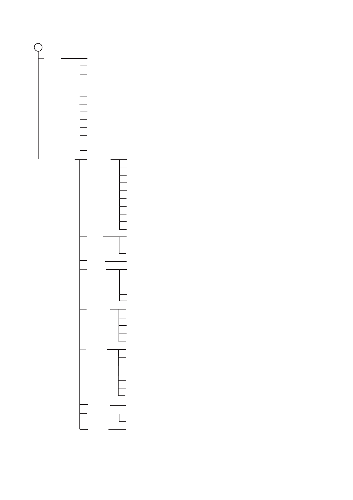
MENU TREE
r,
2
Data
System
Go to WPT (Off, Destination 1 - 20)
WPT List
Nav Display1 (Off, Speed (SOG), Speed (STW), Depth, Range, Bearing, Position,
Wind, Heading, Course, Barom Press, Temp, Time to Go, Trip mete
Odometer, XTE)
Nav Display2 (Same as Nav Display1)
Bearing (True, Mag)
Wind Spd/Dir (True, Apparent)
Trip Source (Off, Own, NMEA)
Temp Source (Off, Own, NMEA)
Speed Source (Off, Own, NMEA)
Trip Reset (Yes, No)
Odo Reset (Yes, No)
Range
Key
Lang
Units
NMEA
Calib
Demo
Tests
Reset
Range 1 (7 - 2500 ft, 15 ft)
Range 2 (7 - 2500 ft, 30 ft)
Range 3 (7 - 2500 ft, 60 ft)
Range 4 (7 - 2500 ft, 120 ft)
Range 5 (7 - 2500 ft, 200 ft)
Range 6 (7 - 2500 ft, 400 ft)
Range 7 (7 - 2500 ft, 600 ft)
Range 8 (7 - 2500 ft, 1000 ft)
Zoom Range (7 - 2500 ft, 15 ft)
B/L Range (10 - 30 ft, 15 ft)
FUNC Key (Pic. Advance, Shift, Interference, Clutter, Color Erase,
White Line, White Marker, WPT List, Bottom Area)
Key Beep (Off, On)
Language (English, OTHERS)
Depth (m, ft, fa, pb, HR)
Temp (°C, °F)
Speed (kt, km/h, mph)
Wind (kt, km/h, mph, m/s)
Distance (nm, km, sm)
NMEA0183 (Ver 1.5, Ver 2.0, Ver 3.0)
NMEA Port (In/Out, In/In)
NMEA Output (Off, On)
WAAS Setup (Off, WAAS-00 - WAAS-27)
TLL Output (Off, TLL, FURUNO-TLL)
Draft (-15.0 - +50.0 ft, +0.0 ft)
Gain ADJ 200 (-20 - +20, +0)
Gain ADJ 50 (-20 - +20, +0)
Temp (-20.0 - +20.0 °F, +0.0 °F)
Speed (STW) (-50 - +50 %, +0 %)
Fish Level (-80 - +100, +0)
Water Type (Salt, Fresh)
Demonstrate (Off, Demo1, Demo2)
Test
LCD Test
Factory Reset (Yes, No)
39
Page 49

FURUNO
SPECIFICATIONS OF ECHO SOUNDER
FCV-620/585
1. GENERAL
1.1 TX Frequency 50 kHz and 200 kHz
1.2 Transmit Method Single or dual frequency transmitting
1.3 Output Power
FCV-620 600 W
FCV-585 600 W or 1 kW selectable
1.4 TX Rate Max. 3,000 pulse/min
1.5 Pulse-length 0.04 to 3.0 ms
1.6 Sensitivity 10 dBµV
2. DISPLAY UNIT
FCV-620/585
2.1 Display System
FCV-620 5.6-inch color LCD, 84.7 mm (W) x 113.3 mm (H), 234 x 320 dots
FCV-585 8.4-inch color LCD, 121 mm (W) x 170 mm (H), 480 x 640 dots
2.2 Display Mode Single frequency (high or low freq.), Dual frequency,
2.3 Expansion Mode Bottom lock, Bottom zoom, Marker zoom
2.4 Basic Range
Unit
1 2 3 4 5 6 7 8
m 5 10 20 40 80 150 200 300 2 to 800
ft 15 30 60 120 200 400 600 1,000 7 to 2,500
fa 3 5 10 20 40 80 100 150 2 to 400
pb 3 5 10 20 50 100 150 200 2 to 450
HR* 4 8 15 30 50 100 150 200 2 to 500
*: Japanese unit of depth measurement
2.5 Range Shift 0 to 800 m, 0 to 2,500 ft, 0 to 400 fa, 0 to 450 pb, 0 to 500 HR
Zoom (high or low freq.), Nav data 1/2, A-Scope
Basic Range
Setting Range
2.6 Zoom Range Bottom lock expansion: 3 to 10 m, 10 to 30 ft
2.7 Display Advance Speed 8 steps (Lines/TX; 4/1, 2/1, 1/1, 1/2, 1/4, 1/8, 1/16, Freeze)
2.8 Function Settings Pic. Advance, Shift, Interference, Clutter, Color Erase, White Line,
2.9 Display Color Echo color: 8, 16 or 64 colors according to echo intensity
SP - 1 E2374S01B-M
Bottom and Marker zoom: 2 to 800 m, 7 to 2,500 ft
White Marker, WPT List, Bottom Area
Background color: White, blue, black, gray or night
Page 50

FURUNO
3. INTERFACE
3.1 Input Data Sentences IEC61162-1 (NMEA0183 Ver 1.5/2.0/3.0)
FCV-620/585
Order of priority
Latitude/Longitude: GGA>RMC>RMA>GLL
Course (true): VTG>RMC>RMA
Course (magnetic): VTG
Ground speed: VTG>RMC>RMA
Water speed: VHW
Distance to waypoint: BWC>RMB
Bearing to waypoint (true): BWC>RMB
Bearing to waypoint (magnetic): BWC
Heading (true): HDT>VHW
Heading (magnetic): HDG>VHW
Cross track error: XTE>RMB
Atmospheric pressure: MDA
Water temperature: MTW
Wind speed and angle (true/apparent): MWV
3.2 Output Data Sentences IEC61162-1 (NMEA0183 Ver 1.5/2.0/3.0), interval: 2 s
DBT, DPT, MTW*, VHW*, TLL* by key operating
*: External data required
4. POWER SUPPLY
4.1 FCV-620 12-24 VDC: 0.8-0.4 A
4.2 FCV-585 12-24 VDC: 1.0-0.5 A
5. ENVIRONMENTAL CONDITION
5.1 Ambient Temperature -15 °C to +50 °C
5.2 Relative Humidity 93 % at 40 °C
5.3 Waterproofing IP55
(IEC60529)
5.4 Vibration ● 2-5 Hz and up to 13.2 Hz with an excursion of ±1 mm ±10 %
(7 m/s
2
maximum acceleration at 13.2 Hz)
● 13.2-100 Hz with a constant maximum acceleration of 7 m/s
6. CHASSIS COLOR
6.1 Display Unit Chassis: N-2.5
Bracket: N-1.75
2
SP - 2 E2374S01B-M
Page 51
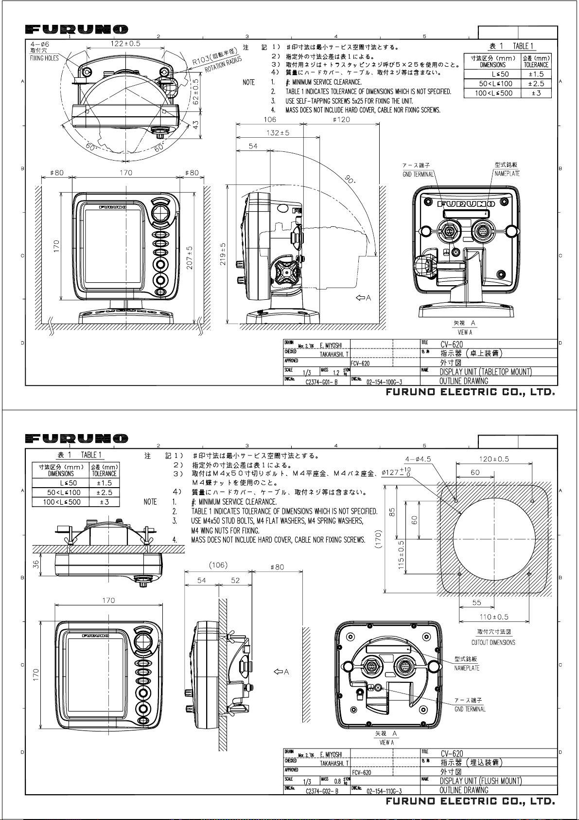
䎼䎑䎃䎫䏄䏗䏄䏌
Ha
tai
電子署名者 : Hatai
DN: cn=Hatai, c=JP - 日本, o=Seigi, ou=Joho,
[email protected]
日付 : 2006.03.02 11:23:20 +09'00'
䎼䎑䎃䎫䏄䏗䏄䏌
Page 52
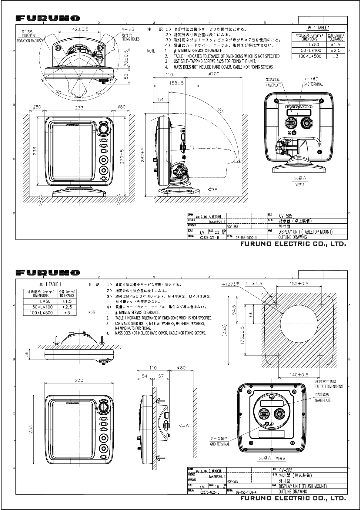
Hatai
電子署名者 : Hatai
DN: cn=Hatai, c=JP - 日本, o=Seigi, ou=Joho, [email protected]
日付 : 2006.03.09 17:17:27 +09'00'
䎼䎑䎃䎫䏄䏗䏄䏌
䎼䎑 䎫䏄䏗䏄䏌
Page 53
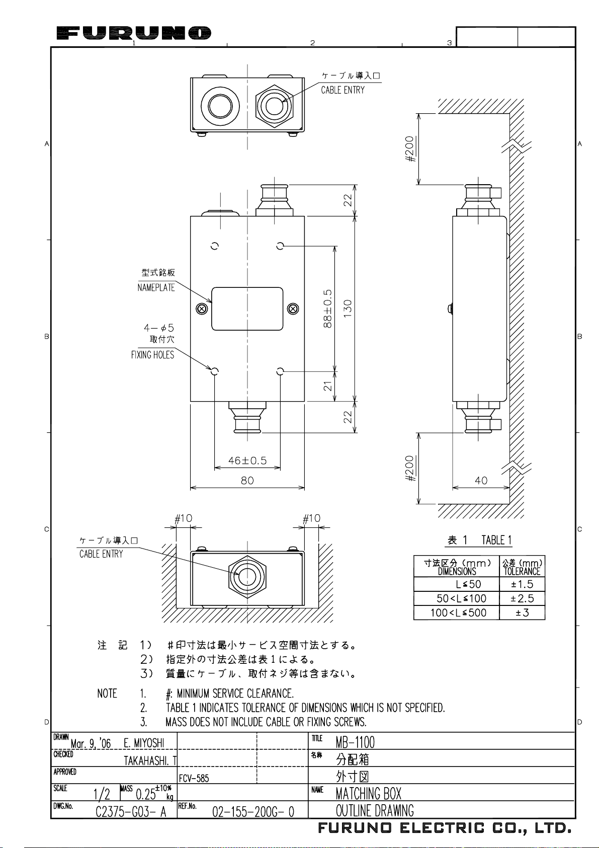
Page 54
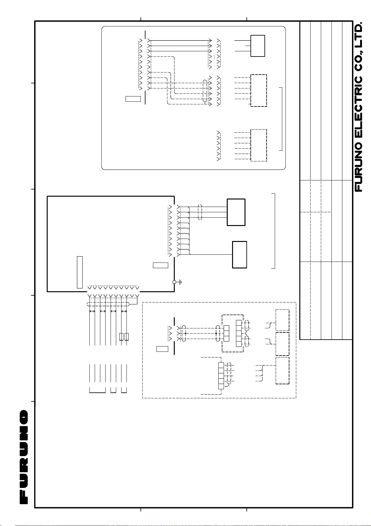
XDR-M
9
XDR-SHIELD
8
XDR-P
7
TEMP0V
6
NC
5
NC
4
TEMP
3
SPD0V/ST-SHIELD
2
12V-P1
1
SPD
XDR
10
MJ-A10SPF
*2
02S4147 0.2m
43
MJ-A10SRMD
10
9
8
2
1
6
5
4
3
2
1
MJ-A6SRMD
6
5
4
3
2
1
*2
XDR-M
XDR-SHIELD
XDR-P
525-5PWD
520-5PSD
520-5MSD
TRANSDUCER
送受波器
NC
NC
+V
SPD
TEMP0V
TEMP
NC
NC
NC
TEMP0V
TEMP
SHIELD
SPD0V/SHIELD
または
OR
*2
ST-02MSB
ST-02PSB
*2
T-02MSB
T-02MTB
T-03MSB
TEMP/SPEED SENSOR
水温・船速センサー
TEMP SENSOR
水温センサー
選択 SELECT
FCV-620/585
カラーLCD魚探
相互結線図
COLOR LCD SOUNDER
INTERCONNECTION DIAGRAM
TITLE
名称
*3
MJ-A10SPF
10
XDR-M
9
XDR-SHIELD
8
XDR-P
7
TEMP0V
6
NC
5
NC
4
TEMP
3
SPD0V/ST-SHIELD
2
12V-P1
1
SPD
XDR
*1
IV-1.25sq.
FCV-585 only
XDR-M
XDR-P
XDR
GND
10
98XDR-SHIELD
1m
MJ-A10SPF
RD-A
RD-B
TEMP-IN
TEMP-IN-0V
DC-P-IN
NC
SHIELD
567
P
チャ BRN
ダイ ORG
DC-M-IN
8
9
P
FUSE(2A)
FUSE(2A)
REDアカ
クロ BLK
10
CV-620
12-24VDC/NMEA
CV-585
KON-004-02M,2m
213
P
WHT
BLU
シロアオキ
YEL
4
P
GRN
ミドリ
DISPLAY UNIT
指示器
2
TD-A
TD-B
FCV-585のみ
MB-1100
8m,φ5.4
525-5PWD
10m,φ5.4
2
13
TB1
531 24
TB2
520-5MSD
520-5PSD
送受波器
または
OR
525ST-MSD
525ST-PWD
水温・船速センサー付
13254
MB-1100
TB2
アカ RED
ミドリ GRN
アオ BLU
クロ BLK
TRANSDUCER
TRANSDUCER
送受波器
アカ RED
クロ BLK
クロ BLK
アカ RED
W/ TEMP/SPEED SENSOR
φ12
10m
(1kW)
φ12
10m
(1kW)
10m,φ12
選択 SELECT
200B-5S
50B-6/6B
50/200-1T
E.MIYOSHI
Mar.9,'06
DRAWN
CHECKED
TAKAHASHI.T
APPROVED
NAME
C2374-C01- C
DWG.No.
12-24 VDC
TEMP SENSOR
水温センサー
NAV EQUIPMENT
航法装置
IEC61162-1
NMEA0183 V1.5/2.0/3.0
1
注記
*1)造船所手配
*2)オプション
A
B
C
*3)コネクタは工場にて取付済み
NOTE
*1. SHIPYARD SUPPLY
*2. OPTION
*3. CONNECTOR PLUG FITTED AT FACTORY.
Page 55
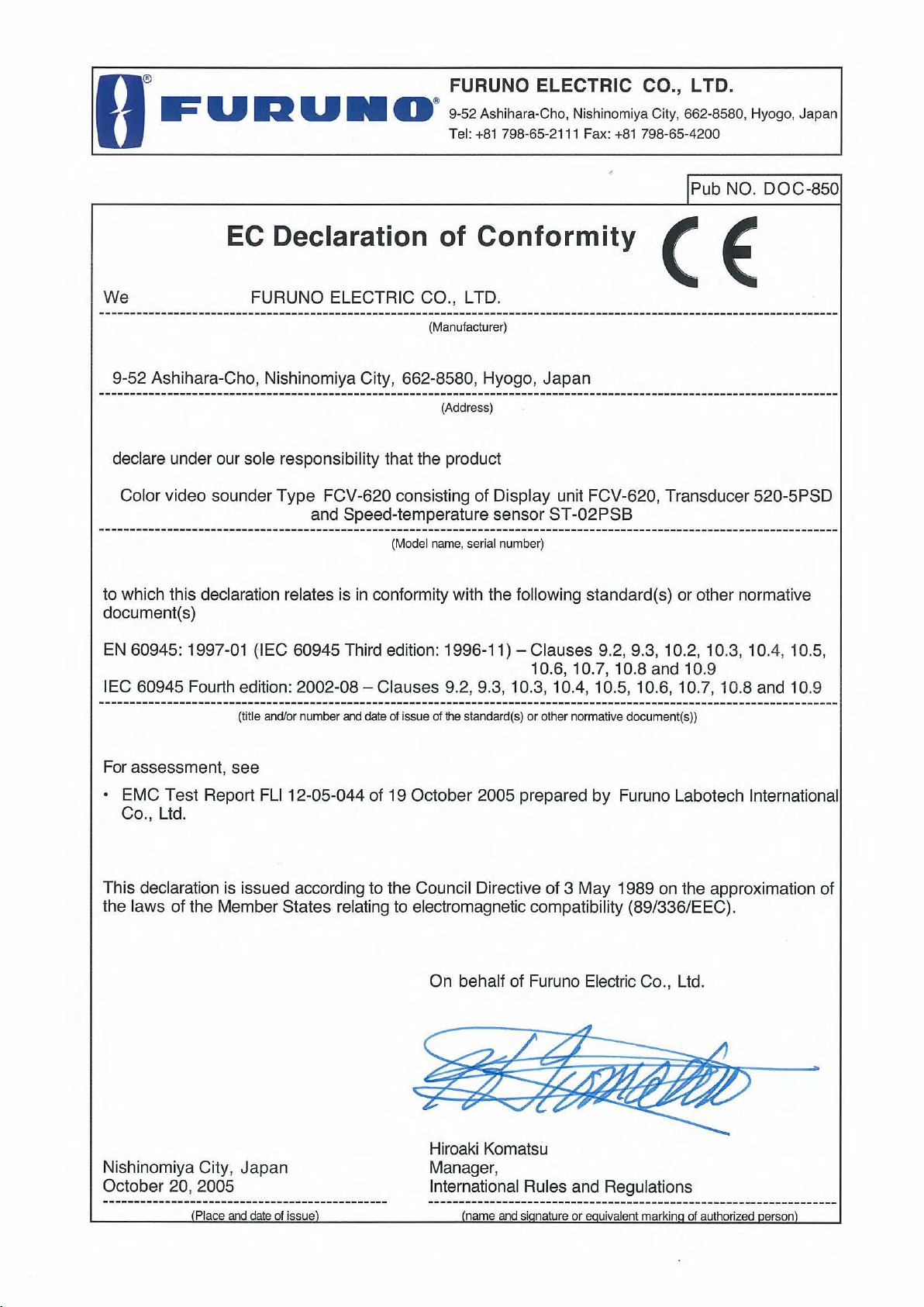
Page 56
FURUNO ELECTRIC CO., LTD.
9-52 Ashihara-Cho, Nishinomiya City, 662-8580, Hyogo, Japan
Tel: +81 798-65-2111 Fax: +81 798-65-4200
Pub NO. DOC-852
EC Declaration of Conformity
We FURUNO ELECTRIC CO., LTD.
-----------------------------------------------------------------------------------------------------------------------
(Manufacturer)
9-52 Ashihara-Cho, Nishinomiya City, 662-8580, Hyogo, Japan
-----------------------------------------------------------------------------------------------------------------------
(Address)
declare under our sole responsibility that the product
Color video sounder Type FCV-585
-----------------------------------------------------------------------------------------------------------------------
(Model name, serial number)
to which this declaration relates is in conformity with the following standard(s) or other normative
document(s)
EN 60945: 1997-01 (IEC 60945 Third edition: 1996-11) – Clauses 10.2 and 10.3
IEC 60945 Fourth edition: 2002-08 – Clauses 9.2, 9.3, 10.3, 10.4, 10.5, 10.8 and 10.9
-----------------------------------------------------------------------------------------------------------------------
(title and/or number and date of issue of the standard(s) or other normative document(s))
For assessment, see
• EMC Test Report FLI 12-05-053 of 14 November 2005 prepared by Furuno Labotech
International Co., Ltd.
This declaration is issued according to the Council Directive of 3 May 1989 on the approximation
of the laws of the Member States relating to electromagnetic compatibility (89/336/EEC).
On behalf of Furuno Electric Co., Ltd.
Nishinomiya City, Japan
November 16, 2005
----------------------------------------------
(Place and date of issue)
Hiroaki Komatsu
Manager,
International Rules and Regulations
------------------------------------------------------------------
(name and signature or equivalent marking of authorized person)
 Loading...