

Furuno 500 User Manual
AUTOPILOT
NAVpilot-500

Thepaperusedinthismanual
9-52 Ashihara-cho,9-52 Ashihara-cho,
A
A
*
0
*
0
*
0
*
0
*
O
*
O
*
O
*
O
Nishinomiya 662-8580, JAPANNishinomiya 662-8580, JAPAN
Telephone :Telephone : 0798-65-21110798-65-2111
FaxFax 0798-65-42000798-65-4200
::
iselementalchlorinefree.
FURUNO Authorized Distributor/DealerFURUNO Authorized Distributor/Dealer
ll rights reserved.
ll rights reserved.
Pub. No.Pub. No. OME-72500OME-72500
(( HIMAHIMA ))
NAVPILOT-500NAVPILOT-500
Printed in JapanPrinted in Japan
FIRST EDITION :FIRST EDITION : APR.APR. 20032003
G1G1 :: OCT.OCT. 17, 200517, 2005
0014698405*
0014698405*
0014698405*
0014698405*
* 0 0 0 1 4 6 9 8 4 0 5 ** 0 0 0 1 4 6 9 8 4 0 5 *
ME72500G10*
ME72500G10*
ME72500G10*
ME72500G10*
* O M E 7 2 5 0 0 G 1 0 ** O M E 7 2 5 0 0 G 1 0 *
SAFETY INSTRUCTIONS
WARNING
Do not open the equipment
unless you are well familiar
with electrical circuits.
Only qualified personnel
ELECTRICAL
SHOCK
HAZARD
Do not set the course changing speed
too high.
The boat will be turned too sharply at the
course change, which could create a very
dangerous situation.
Do not use the autopilot in the
following situation:
Harbor entrance or narrow channel
Where vessels change course often,
such as a cape or small island
should work inside the
equipment.
WARNING
Do not use the ORBIT mode in rough
sea.
Because the boat turns a 360-degree circle
around the waypoint a large wave or strong
wind can cause the boat to capsize.
For the figure eight mode, confirm that
no objection is in the general vicinity
of the waypoint.
The distance from the waypoint to the
turning point depends on boat's speed.
Do not use the SIMULATION mode on
the boat.
The rudder may move. This is specialpurpose mode for technicians.
CAUTION
Observe the following cautions when
using the autopilot:
Maintain a vigilant watch
Watch for drifting of vessel
In an emergency, manually steer the
vessel.
The autopilot cannot avoid vessels, etc.
automatically.
Set the turn rate properly.
Setting the too high rate may cause
sudden turn.
When connecting a geomagnetism detection
type heading sensor, correct magnetic field
deviation. If an autopilot is used without the
compensation, unexpected course change
may occur.
In case of power failure turn off the
autopilot or manually steer the vessel.
Leaving the equipment in the AUTO or
NAV mode during power failure will cause
wear on the rudder mechanism.
Use the correct fuse.
Use of a wrong fuse can cause fire or
damage the equipment.
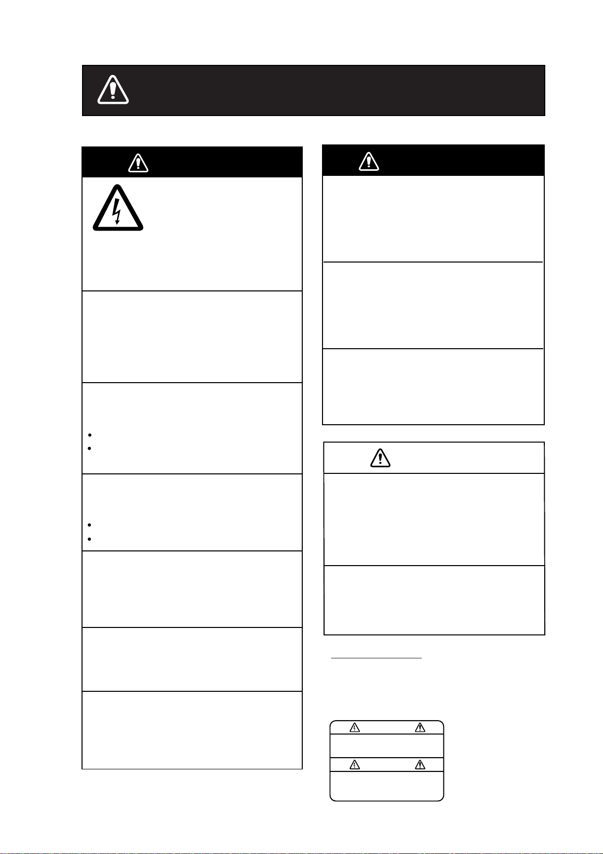
WARNING LABEL
A warning label is attached to the
processor unit. Do not remove the
label. If the label is missing or damaged,
contact your dealer about replacement.
To avoid electrical shock, do not
remove cover. No user-serviceable
parts inside.
WARNING
Name: Warning Label (1)
Type: 86-003-1011
Code No.: 100-236-231
i

TABLE OF CONTENTS
FOREWORD ........................................................................................................iv
SYSTEM CONFIGURATION.................................................................................v
1. PRINCIPLE OF THE AUTOPILOT................................................................ 1-1
1.1 Principle of Autopilot ....................................................................................................1-1
1.2 Principle of Operation ..................................................................................................1-2
2. BASIC OPERATION...................................................................................... 2-1
2.1 Operating Controls.......................................................................................................2-1
2.2 Turning On/Off..............................................................................................................2-2
2.3 Adjusting Brilliance and Contrast.................................................................................2-3
2.4 Displays .......................................................................................................................2-3
2.4.1 Choosing the display mode.................................................................................2-3
2.4.2 Selecting the data shown on Normal Display 2,
Data Display and Graphic Display......................................................................2-4
3. STEERING MODES ...................................................................................... 3-1
3.1 STBY Mode..................................................................................................................3-1
3.2 AUTO Mode.................................................................................................................3-2
3.2.1 Using the AUTO mode........................................................................................3-2
3.2.2 ADV ANCED AUTO mode....................................................................................3-3
3.3 NAV Mode....................................................................................................................3-4
3.3.1 Starting the NAV mode........................................................................................3-4
3.3.2 Selecting sailing method of NAV mode...............................................................3-5
3.3.3 Switching waypoint..............................................................................................3-6
3.3.4 Selecting the boat’s steering behavior after
arriving at your destination waypoint...................................................................3-7
3.4 TURN Mode.................................................................................................................3-8
3.5 REMOTE Mode..........................................................................................................3-16
3.6 DODGE Mode............................................................................................................3-20
3.6.1 Dodging in STBY mode.....................................................................................3-20
3.6.2 Dodging in AUTO or NAV mode........................................................................3-21
4. MENU OPERATION ...................................................................................... 4-1
4.1 STBY Mode Menu........................................................................................................4-1
4.1.1 Setting parameters..............................................................................................4-2
4.1.2 Setting other menu items..................................................................................4-10
ii

5. ALARMS........................................................................................................ 5-1
5.1 ALARM Menu............................................................................................................5-1
5.1.1 Selecting the alarm buzzer................................................................................5-2
5.1.2 Selecting the beep pattern................................................................................5-2
5.1.3 Setting the watch alarm ....................................................................................5-3
5.1.4 Setting the heading deviation alarm..................................................................5-3
5.1.5 Setting the cross-track error limit.......................................................................5-4
5.1.6 Setting the speed alarm....................................................................................5-5
5.1.7 Setting the depth alarm.....................................................................................5-6
5.1.8 Setting the temperature alarm...........................................................................5-7
5.1.9 Setting the trip distance alarm...........................................................................5-7
5.1.10 Clearing the trip distance ................................................................................5-8
5.2 Alarm Information......................................................................................................5-9
6. MAINTENANCE & TROUBLESHOOTING ...................................................6-1
6.1 Preventive Maintenance ............................................................................................6-1
6.2 Replacement of Fuse.................................................................................................6-2
6.3 Diagnostics................................................................................................................6-2
6.4 Clearing Memories.....................................................................................................6-6
6.5 Error Messages.........................................................................................................6-7
MENU TREE................................................................................................... MN-1
SPECIFICATIONS........................................................................................... SP-1
INDEX............................................................................................................... IN-1
iii

FOREWORD
A Word to the Owner of the NAVpilot-500
Congratulations on your choice of the FURUNO NAVpilot-500 AUTOPILOT.
For over 50 years FURUNO Electric Company has enjoyed an enviable reputation for
innovative and dependable marine electronics equipment. This dedication to excellence is
furthered by our extensive global network of agents and dealers.
Your autopilot is designed and constructed to meet the rigorous demands of the marine
environment. However, no machine can perform its intended function unless installed,
operated and maintained properly. Please carefully read and follow the recommended
procedures for operation and maintenance.
We would appreciate hearing from you, the end-user, about whether we are achieving our
purposes.
Thank you for considering and purchasing FURUNO equipment.
Features
• Self-learning program to continuously improve the steering parameters for safe and
expeditious navigation
• Two steering modes – AUTO (Heading Control System) and NAV (Track Control System)
• Dodging from the control unit or remote controller
• Available for solenoid drive and reversible hydraulic
• Max. six control units may be connected (using two ports of the processor unit)
• Menu operation for simplified control
• Display modes: Autopilot/Track control modes with rudder angle, L/L, Highway, Two
customized displays, compass rose
iv
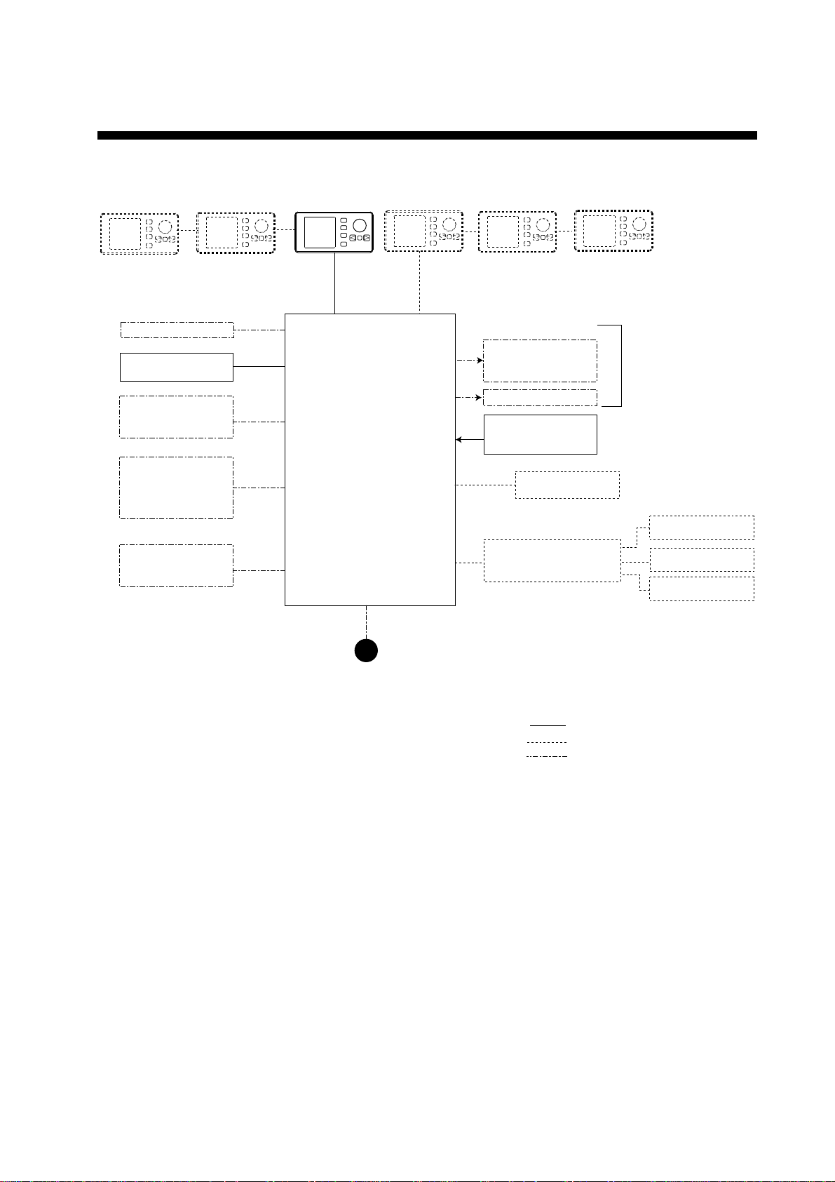
SYSTEM CONFIGURATION
Control Unit*
FAP-5001 (Max. 6)
PC
Heading sensor
PG-500
External buzzer
GPS Navigator
(NMEA0183)
RD-30 (Max. 3)
(NMEA0183)
*: Any combination of FAP-5001 and FAP-5011 is available.
Processor Unit
FAP-5002
12-24 VDC
Reversible pump or
Electromagnetic valve unit
Clutch
Rudder Reference Unit
FAP-6111
Remote Controller
Distributor FAP-6800
Remote controler
Dial type: FAP-5551, FAP-5552
Button type: FAP6211, FAP-6212
Lever type: FAP-6221, 6222
Dodge type: FAP-6231, 6232
: Standard supply
: Option
: User supply
Ship’s steering system
Remote Controller
Remote Controller
Remote Controller
System configuration of NAVpilot-500
v

This page is intentionally left blank.
vi

1. PRINCIPLE OF THE AUTOPILOT
1.1 Principle of Autopilot
An autopilot is an automatic device for steering a vessel and maintaining its
heading in an intended direction. Boat and ship operators can really appreciate
the advantages of the autopilot – It steers the boat for you so that you are free to
carry out navigational checks, trim adjustments, etc. or to simply relax and enjoy
the ride.
The NAVpilot-500 autopilot utilizes a proportional rate system to steer the boat.
This system is similar to the highly accurate and reliable systems used on
aircraft, missiles and space vehicles. The proportional rate autopilot provides the
necessary course correction to the steering system relative to the speed and
amount that the boat moves off course.
Dead band is the area (in degrees) that an autopilot is allowed to drift before
correcting the vessel’s course. Since your NAVpilot-500’s advanced processor
does not utilize a dead-band, it will not drift or wander, and will steer the boat
reliably and accurately, taking action if even a minute course error occurs.
Because wandering is eliminated, the proportional rate autopilot uses less power
and lowers wear and tear on the steering system. Course correction is smooth,
and consistent, and the boat will not jerk back and forth at any speed.
1-1

1. PRINCIPLE OF THE AUTOPILOT
1.2 Principle of Operation
In the AUTO modes, the heading information from a heading sensor is
continuously compared with the course that is set on the autopilot’s controller. (in
the NAV mode, the course to the waypoint is received from a plotter connected
to the NAVpilot-500). With the boat on course, these two signals are equal.
If the boat drifts off course, the difference between the primary heading and the
set course will change proportionally and there will be an imbalance at a
comparator. The comparator’s output will then move up or down depending on
whether the course error is to the left or right of the set course.
The rudder will continue to turn the vessel until a balanced condition is obtained
at the comparator, at which point the drive to the rudder stops.
The rudder position is determined by a rudder reference unit and continuously
monitored by the processor unit.
1-2
2. BASIC OPERATION
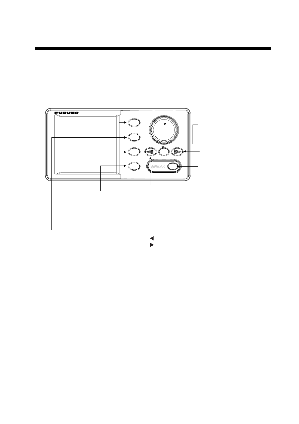
2.1 Operating Controls
Course control knob**
Rotate: Selects menu items and options.
STBY key
Selects the STBY (manual) mode.
Push: Sets the course on Auto or Nav mode.
MENU key
Opens the mode menus.
NAV key
Selects the NAV mode.
AUTO key
Selects the AUTO mode.
STBY
AUTO
NAV
MENU
PORT key*
Steers the boat to port.
TURN
*: Described as below in the text.
: [PORT] key
: [STBD] key
**: This knob is called "ENTER KNOB" in the menu instructions.
TURN key
Open the TURN menu.
STARBOARD key*
Steers the boat to starboard.
POWER/BRILL key
Long press: Turns power off.
Mormentary press: Turns power on;
opens the display for adjustment of
brilliance and contrast.
Control unit, front view
2-1
2. BASIC OPERATION
2.2 Turning On/Off
Press the [POWER/BRILL] key to turn the unit on. (For PG-500, see Note 2
shown below.) A beep sounds and the equipment proceeds in the sequence
shown below, showing product information and startup test results. The startup
test checks the ROM, RAM, backed up data and communication between the
control unit and processor unit, and also checks for the presence of heading
from the sensor and rudder angle information from the rudder angle indicator. If
NG appears, an appropriate message will also appear on the screen. If NG is
shown, contact your dealer for advice.
AUTO PILOT
NAVPILOT-500
FURUNO ELECTRIC CO., LTD
START UP TEST
ROM
PROCESSOR OK 6454002-**.**
CONTROL OK 6454001-**.**
RAM
PROCESSOR UNIT OK
CONTROL UNIT OK
BACK UP DATA
PROCESSOR UNIT OK
CONTROL UNIT OK
HEADING DATA OK 359.9
6454101-**.**
RRU OK P12.3
CONTROLLER ID 1
**.** : Program version no.
Startup sequence
After the startup test is completed, “STBY” appears on the screen. This means
that the equipment may now be operated manually by pressing the PORT /
STBD buttons.
Note 1: The first time you turn on the power, you are asked which mode is used
from among Normal, Installation and Simulation. Rotate the course
control knob to select the appropriate mode, and then press the knob.
Note 2: When the Integrated Heading Sensor PG-500 is connected, turn on the
NAVpilot-500 and wait four minutes before leaving port in order to allow
time for the PG-500 heading data to stabilize.
Turning the power off
Press and hold down the [POWER/BRILL] key until the screen goes blank.
2-2
2.3 Adjusting Brilliance and Contrast
The brilliance and contrast can be adjusted as below:
1. Momentarily press the [POWER/BRILL] key. The CONTRAST and BRILL
window appears.
2. BASIC OPERATION
CONTRAST
BRILL
PORT
Contrast, brilliance window
2. Rotate the course control knob to adjust display contrast; clockwise to raise
the contrast and counter-clockwise to lower it. (16 levels are available.)
The contrast can also be adjusted by pressing the [POWER/BRILL] key.
3. Press the [PORT] or [STBD] key to adjust display brilliance, [PORT] to lower
the brilliance and [STBD] to raise it. (Eight levels are available.)
To close the CONTRAST and BRILL window, press any key except the
[POWER/BRILL], [STBD] or [PORT] key.
2.4 Displays
2.4.1 Choosing the display mode
10
8
STBD
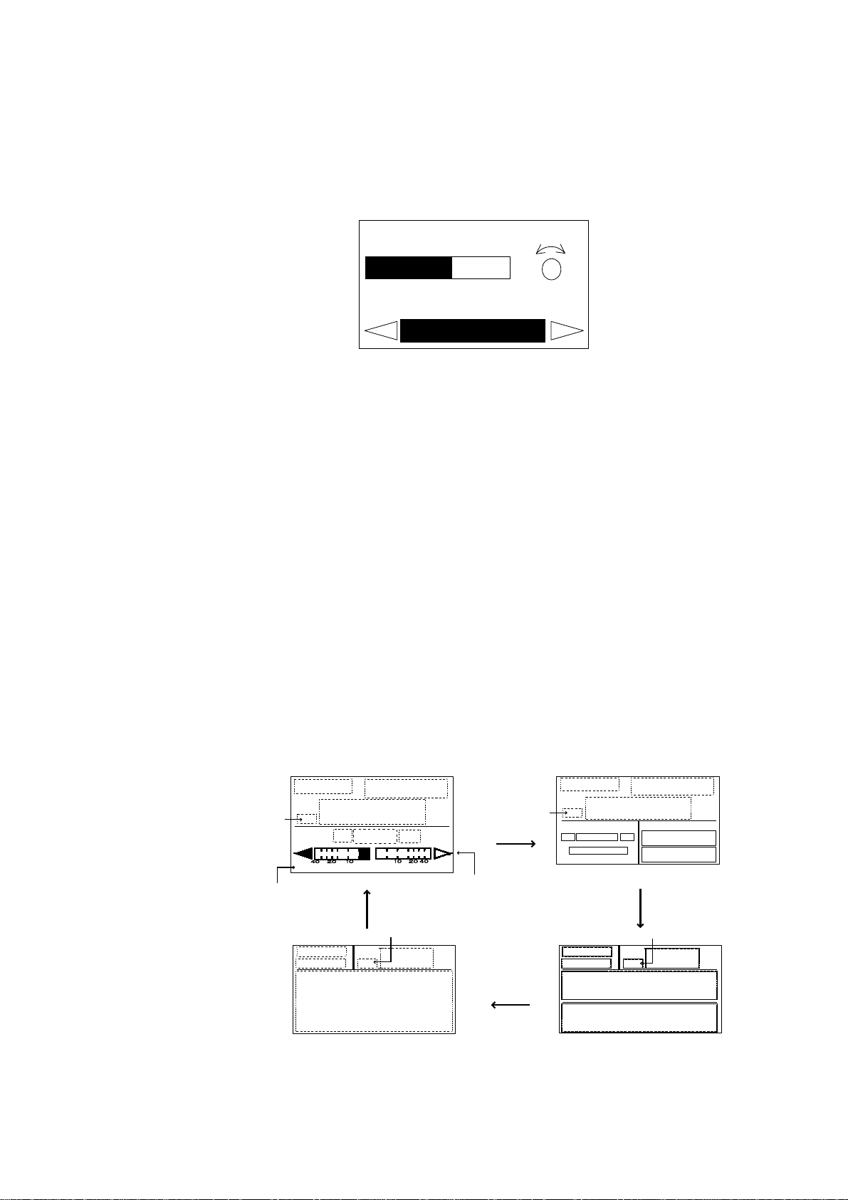
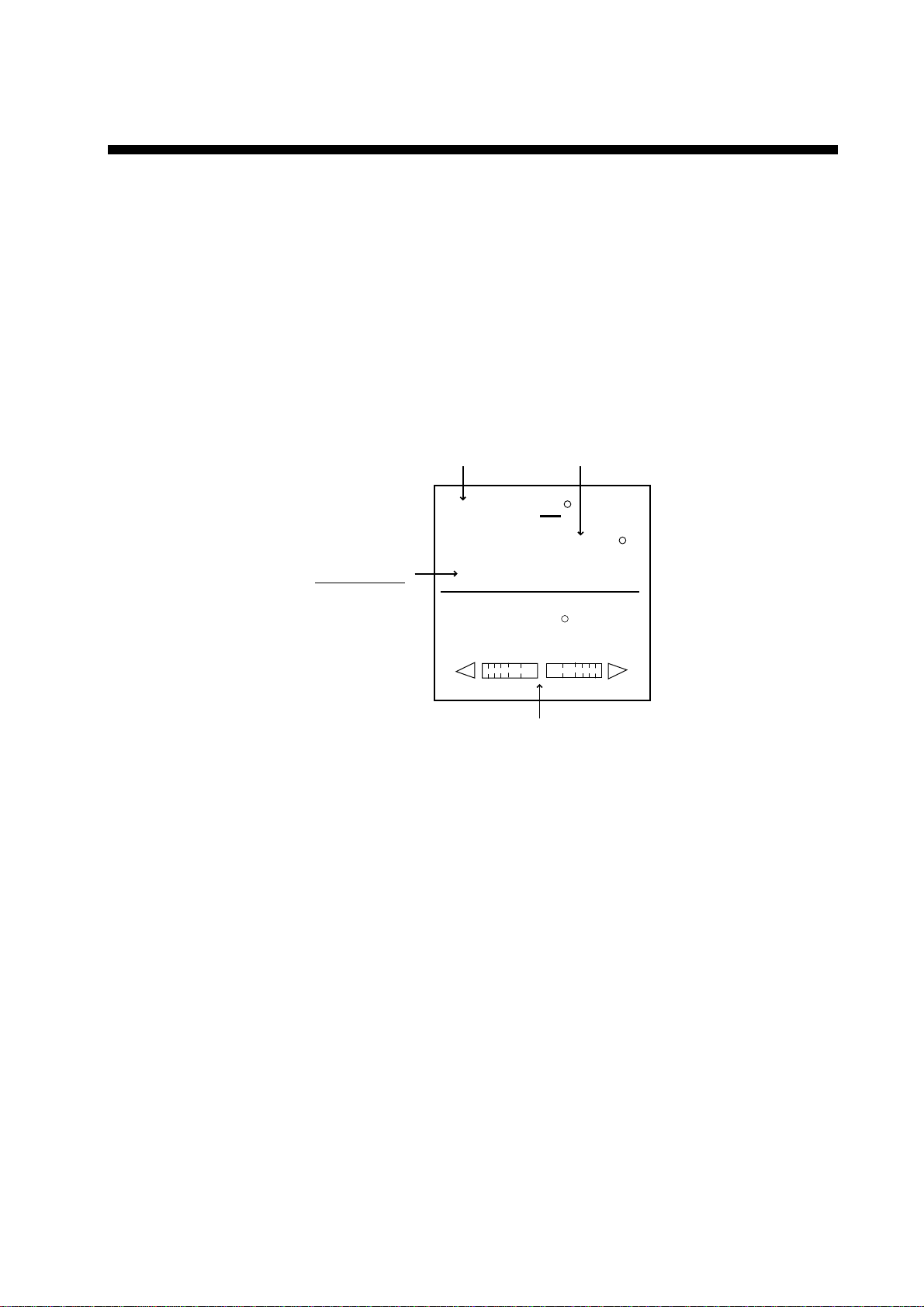
There are four types of displays: Normal display 1 (page 1), Normal display 2
(page 2), Data display (page 3) and Graphic display (page 4).
To choose a display mode, press a mode key (AUTO, NAV or STBY). Each time
a mode key is pressed the display changes in the sequence shown below.
Heading mode
Page No.
(Mode)
HDG
[1]
(Mode)
(Course)
[4]
(Course)
(Heading)
P
(Data)
S
(Normal display 1)
Heading mode
HDG
(Graphic)
(Graphic display)
Heading mode
Analog indicator
(Mode)
HDG
(Data)
P
[2]
(Normal display 2)
(Mode)
(Course)
[3]
(Data display)
(Heading)
S
HDG
HDG
(Data1)
(Data 2)
(Course)
(Data1)
(Data 2)
Heading mode
(Heading)
Displays
2-3
2. BASIC OPERATION
2.4.2 Selecting the data shown on Normal Display 2, Data Display
and Graphic Display
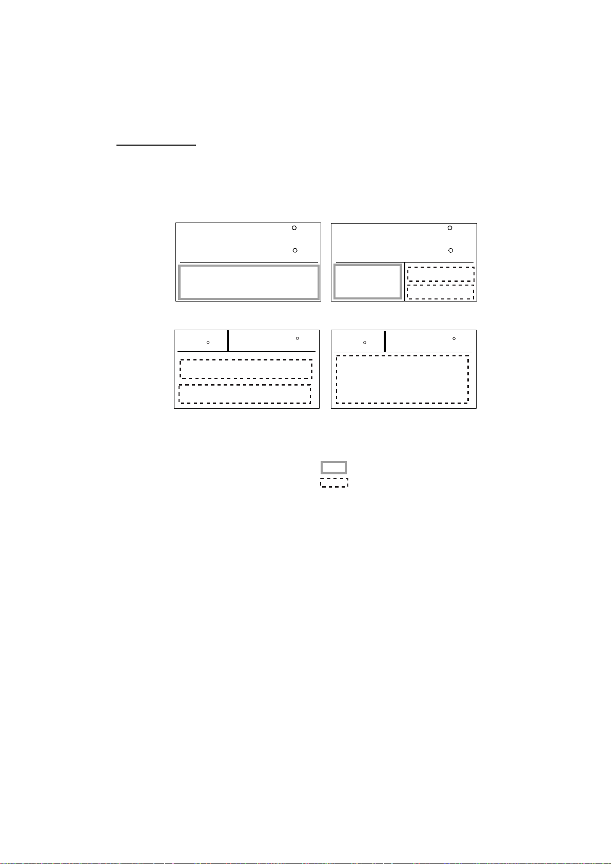
Display modes may be set up to suit your operating needs as below.
Selecting data
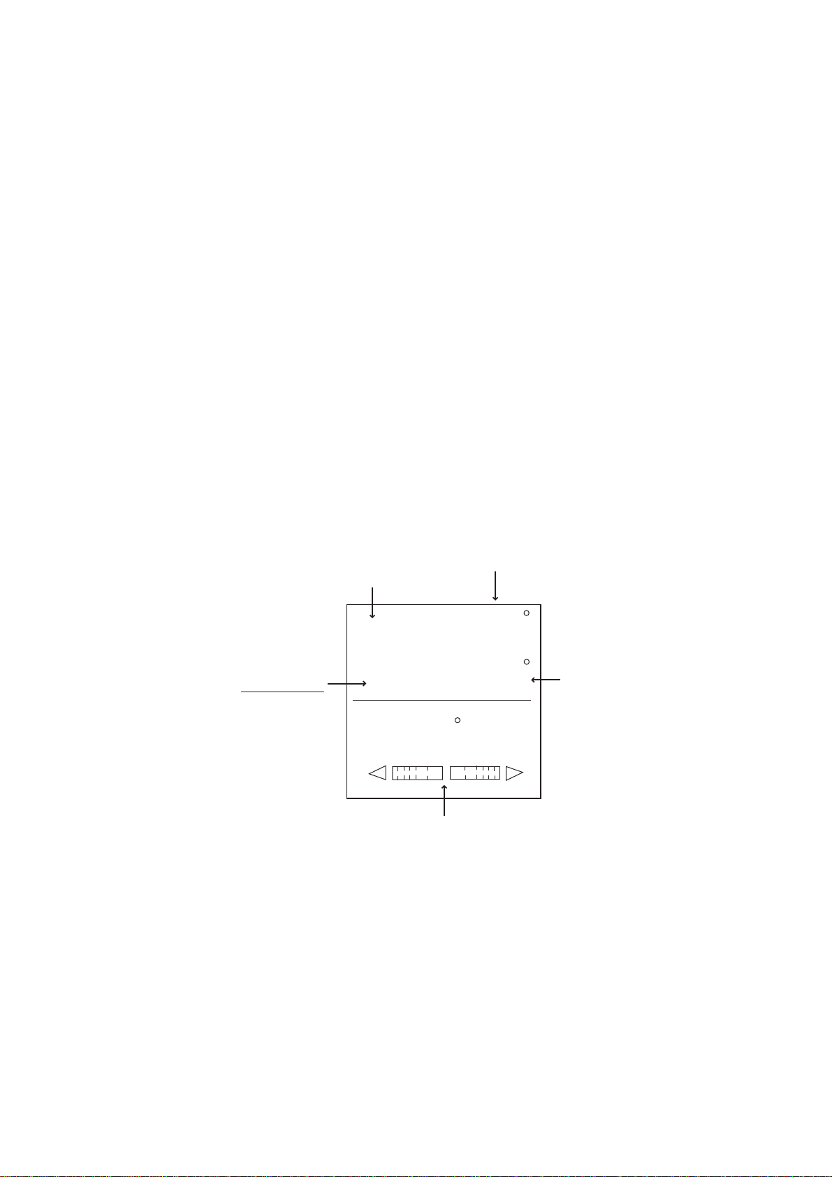
In the STBY mode, you can select which data you want to display in the columns
shown in the figure below. For Normal Display 1 and 2, you may choose which
data you want to show on the analog indicator.
STBY
HDG
STBY
20.4
20.5
145.9
Normal Display 1
HDG
Data Display*
116.5
*: Two or three data can be selected on installing.
STBY
HDG
Normal Display 2
STBY
20.4
HDG
Graphic Display
Analog indicator column
Data column
20.5
145.9
116.5
1. Press the [STBY] key to show the STBY mode.
2. Press the [STBY] key several times to show the one of screens shown above,
which you want to change the data.
3. Press the course control knob.
The first column is circumscribed with a rectangle.
4. Press the [PORT] or [STBD] key to select the column desired.
Note that there is one column in the Normal Display 1 and Graphic data.
5. Rotate the course control knob to select the data you want to show.
Available data and analog indicators are listed on the next page.
6. Press the course control knob to finish.
2-4

2. BASIC OPERATION
Data available for Normal display 2, Data display and Graphic display
Item Displayed data
POS Own ship’s position (L/L)
COG Course over ground
SOG Speed over ground
STW Speed through water
TEMP Water temperature
DPT Depth
BRG Bearing to waypoint
RNG Range to waypoint
WPT Waypoint position (L/L)
XTE Cross-track error
TTG Time-to-Go to Destination
ETA Estimated Time of Arrival
DATE Date
TIME Time
WIND TRUE* Wind direction and speed (True)
WIND RELATIV** Wind direction and speed (Relative)
VOLT Input/output power voltage to the processor unit
TRIP Trip distance
*True: The Speed and direction (relative to due north)
**Relative: The direction (in relation to ship’s bow) and speed of the wind as it
appears to those on board, relative to the speed and direction of
the boat; combination of the true wind and the wind caused by the
boat’s movement.
Analog indicator selection
Item Displayed data
RUDDER ANGLE Rudder angle
DEVIATION Deviation of heading
RUDDER/XTE Rudder angle will appear while in the STBY and AUTO
modes, XTE will appear while in the NAV mode.
DEVIATION/XTE Deviation will appear in the STBY mode and AUTO modes,
XTE will be shown while in the NAV mode.
2-5
2. WIRING
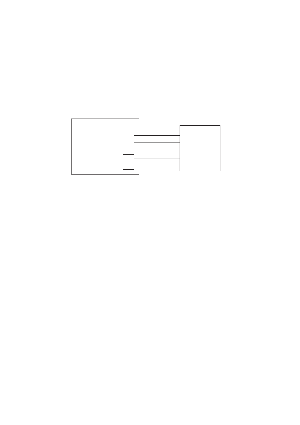
2.2.4 Conne ct io n of Terflex
When connect ing the Teleflex ® linear sensor AR4102/AR4302 instead of the FAP-611 1, do
the following modific ati on.
1. Cut the black jumper at t he bac k of the AR4102/4302.
DO NOT cut the red jumper.
2. Make the cable connecti on as s hown below.
3. Change the positi on of jumper switch JP - 2 from #3-4 to #1-2, referr ing to the illustration
shown on page 2-4.
4. Set SELECT RRU to “ LINEAR SENSOR” on the DOCKS IDE SETUP m enu. For further
details, see chapter 3.
Processor unit
SPU Board
(64P1140)
®
linear se ns or
TB13
1
2
3
4
5
RED
WHT
BLK
Linear sensor
AR4102
or
AR4302
For BARE line, wind tape around where shield was removed.
Connection of linear sensor AR4102/AR4302
2-6
3. STEERING MODES
The NAVpilot-500 system is capable of six primary steering modes: STBY
(manual), AUTO, NAV, TURN, REMOTE (FU and NFU) and DODGE.
3.1 STBY Mode
After turning on the power, the equipment goes to the STBY mode.
This is a manual steering mode. W hen sailing into or out of a harbor, steer the
vessel in the STBY mode by using the ship’s steering wheel (helm).
Press the [STBY] key.
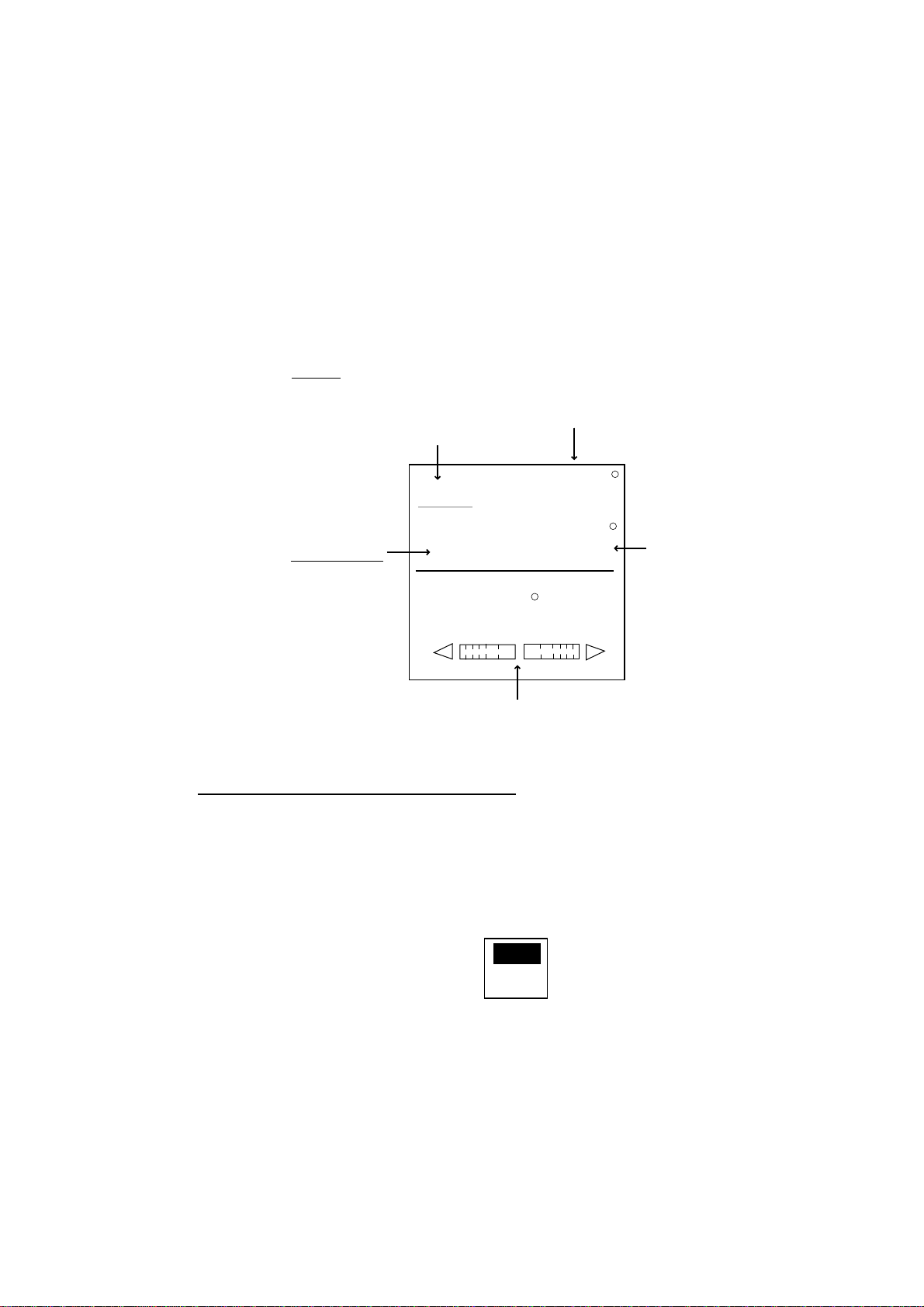
STBY mode
(manual steering mode)
Heading from heading sensor
STBY
HDG
Heading mode
M: Magnetic
T: True
M
RUDDER
359.9
0
20
40
10
Rudder angle (XTE or Deviation)
STBY mode display (ex. Normal Display 1)
Note: In the STBY mode, you can choose PORT 1 or PORT 2 for NAV mode by
pressing the [NAV] key immediately. For details, see page 3-4.
40
10
20
3-1
3. STEERING MODES
3.2 AUTO Mode
3.2.1 Using the AUTO mode
The NAVpilot-500’s AUTO mode steers the boat automatically on a course set by
the operator.
Note: The AUTO mode will not compensate for the effects of wind or tide, which
can push you off course in the athwart ship direction. Use the AUTO mode
for short, straight voyages. Otherwise switch to the NAV mode which is
described on page 3-4.
1. Direct the boat to the intended course desired.
2. Press the [AUTO] key to activate the Auto mode.
Your boat will automatically maintain the current course at the moment the
[AUTO] key is pressed.
Whenever the heading deviates from the set course, the NAVpilot-500
automatically adjusts the rudder to return the boat to the set course.
3. To change or readjust the course setting in the AUTO mode, simply rotate the
course control knob to the desired course.
4. Press the [STBY] key to leave AUTO steering in an emergency. You can
steer your boat by the helm.
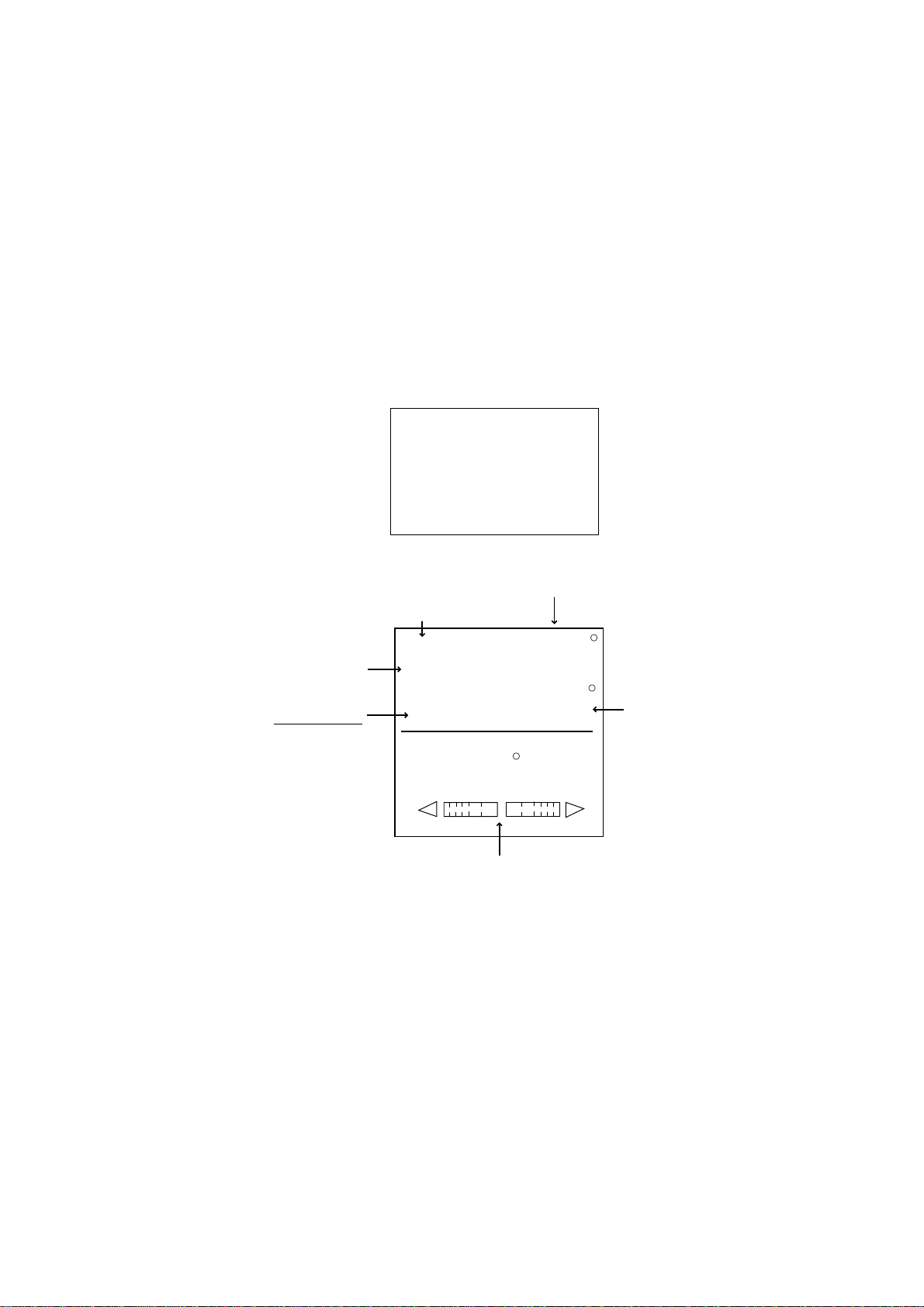
Heading control mode
(AUTO mode)
Course selected by
the course control knob
Heading mode
M: Magnetic
T: True
AUTO mode display (Normal display 1)
AUTO
359
HDG
M
RUDDER
359.9
0
20
40
Rudder angle (XTE or Deviation)
10
10
20
40
Heading from
heading sensor
3-2
3.2.2 ADVANCED AUTO mode
AUTO mode will maintain a set course, but your vessel’s course may be shifted
by the effects of current or wind. ADVANCED AUTO mode maintains a set
course while compensating for the effects of wind and tide. Note that your
NAVpilot-500 must be connect ed to a (GPS) which outputs own ship’s position
data (L/L) in NMEA0183 format to the NAVpilot-500.
In the ADVANCED AUTO mode, the NAVpilot-500 will calculate your course
based on your present position and heading, and by setting a virtual “waypoint”
in its memory to navigate towards. If either tide or wind begins to push you off
course, the NAVpilot-500’s processor will correct your heading accordingly. In
this mode, “AUTO
” appears on the display.
ADVANCED AUTO
(Indicated with underline)
3. STEERING MODE
Course selected by
the course control knob
AUTO
359
HDG
Heading mode
M: Magnetic
T: True
M
RUDDER
359.9
Heading from
heading sensor
0
20
40
Rudder angle (DEVIATION or XTE)
ADVANCED AUTO mode display (ex. Normal display 1)
Enabling the ADVANCED AUTO mode
You can select whether to use the ADVANCED AUTO mode or not as follows.
1. In the AUTO mode, press the [MENU] key to sho w the AUTO mode menu.
2. Rotate the course control knob to select “ADVANCED AUTO”, and then
press the course control knob to show the advanced auto options window.
10
10
20
40
OFF
ON
Advanced auto options window
3. Rotate the course control knob to select “ON”.
When you want to finish the ADVANCED AUTO mode, select “OFF”.
4. Press the course control knob to close the menu.
Note: You can s witch AUTO mode and ADVANCED AUTO mode by holding the
[AUTO] menu down until the message “ADVANCED AUTO ON (OFF)”
appears.
3-3
3. STEERING MODES
3.3 NAV Mode
3.3.1 Starting the NAV mode
If a destination waypoint is set on a GPS / Plotter, the NAVpilot-500 can receive
this information and guide t he boat to the destination waypoint as determined by
the plotter. To use the NAV mode, complete the following steps.
Note: It takes 5 seconds to activate the NAV mode after the NAVpilot-500
receives the above information.
1. Set the destination waypoint (or route) on the plotter.
2. Manually steer the boat towards the waypoint.
3. Press and hold the [NAV] key down until the following message appears.
NAV TO _ _ _ _ _ _ _
FROM PORT 1?
ARE Y OU SURE?
YES...PUSH ENTER KNOB.
NO.....PUSH ANOTHER KEY.
4. Press the course control knob to go to the NAV mode.
Course to the destination waypoint
Track control mode (NAV)
Selected
Navigator
NAV
SRC: PORT 1
359
HDG
Heading mode
M: Magnetic
T: True
M
RUDDER
359.9
Heading from
heading sensor
0
20
40
Rudder angle (or XTE)
NAV mode display (Normal display 1)
Note that while in the NAV mode, the course reading on the NAVpilot-500 will not
always be the same as the waypoint direction shown on the plotter.
When you want to navigate a route, make sure that your plotter is navigating
towards the nearest or desired waypoint before putting the NAVpilot-500 into the
NAV mode.
5. Press the [STBY] key to terminate the NAV mode.
Note: You can change t he port to use by pressing the course control knob over
three seconds.
10
10
20
40
3-4
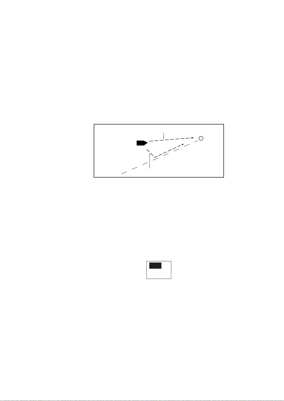
3.3.2 Selecting sailing method of NAV mode
When your vessel goes off course while navigating between the origin (previous
waypoint) and your current destination waypoint because of a remote control
command, etc. the NAV mode uses one of two methods to get back on course:
COURSE or XTE. (See figure in below.) If COURSE is selected, the
NAVpilot-500 will calculate a new course based on your new position after
dodging, etc. that will take you directly to your destination waypoint. If XTE is
selected, the NAVpilot-500 will use XTE or cross track error to steer the boat
towards your ORIGINAL course before dodging. You may select, either
COURSE or XTE as shown below.
COURSE line
3. STEERING MODE
Waypoint
Original course
XTE line
NAV mode, COURSE and XTE
The NAV mode steering method can be selected from the menu.
1. In the NAV mode, press the [MENU] key to show the NAV mode menu.
2. Rotate the course control knob to select “NEXT PAGE”, and then press the
course control knob to show page 2.
3. Rotate the course control knob to select “NAV MODE” on the second page,
and then press the course control knob to show the nav mode options
window.
XTE
COURSE
Nav mode options window
4. Rotate the course control knob to select XTE or COURSE as appropriate.
5. Press the course control knob, and then press the [MENU] keys twice to
close the menu.
3-5

3. STEERING MODES
3.3.3 Switching waypoint
When you arrive at a waypoint on a route while in the NAV mode, you can switch
to the next waypoint automatically or manually. The AUTO setting will
automatically switch to the next destination waypoint when your boat is within
the arrival alarm area (set on the plotter). The MANUAL setting requires operator
confirmation (pressing the course control knob) before switching to the next
waypoint. When in MANUAL switching mode, the NAVpilot-500 will sound for five
seconds an alarm when the vessel arrives at the destination waypoint.
AUTO: When your boat is within the arrival alarm area, the buzzer sounds
for five seconds and the message “WPT WAS CHANGED”
appears.
MANUAL: The message “WPT WAS CHANGED. PRESS ANY KEY.” appears
when the vessel arrives at the destination waypoint.
1. In the NAV mode, press the [MENU] key to show the NAV mode menu.
2. Rotate the course control knob to select “WAYPOINT SWITCHING”.
3. Press the course control knob to show the waypoint switching window.
AUTO
MANUAL
Waypoint switching options window
3. Rotate the course control knob to select AUTO or MANUAL as appropriate.
4. Press the course control knob and [MENU] key in order to close the menu.
3-6
 Loading...