

Furuno 235DHT-LMSE Installation Instructions
OWNER’S GUIDE & INSTALLATION INSTRUCTIONS
IMPORTANT : Please read the instructions completely before proceeding with the installation.
These instructions supersede any other instructions in your instrument manual if they differ.
WARNING
Installation of the anti-rotation bolt is mandatory!
Failure to install the anti-rotation bolt may result in the fairing rotating while the
17-284-01 rev. 02 06/04
boat is underway. The effect may be violent movement and loss of steering. This
could result in serious injury or death to passengers and/or damage to the boat
or other property.
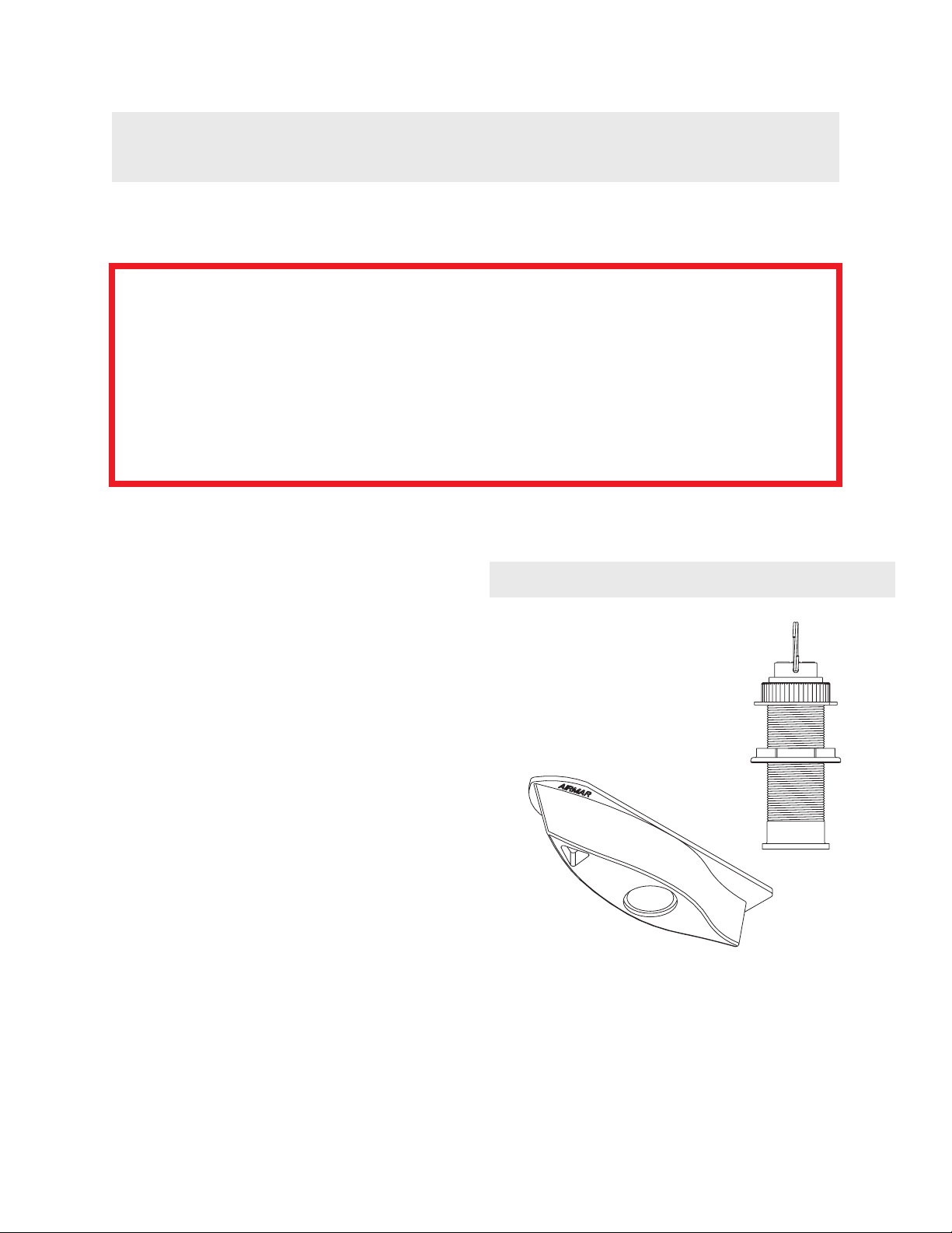
Retractable Thru-Hull Transducer
with High-Performance Fairing
Model: B122
Applications
• Bronze housing recommended for fiberglass or wood hulls only.
Caution : NEVER install a bronze housing in a metal hull
because electrolytic corrosion will occur.
• Caution : NEVER install a metal housing in a vessel with a
positive ground system.
• Maximum hull thickness with fairing (measured perpendicular to
the water surface): 47mm (1-7/8")
•Fairing can accommodate a deadrise angle of up to 35 °
Pre-test
Connect the transducer insert to the instrument. Hold the
transducer over the side of the boat with the active surface
submerged in the water and aimed at the bottom. Check for a depth
reading (and temperature if applicable). If there is no reading, check
all the connections and repeat the test. If there is still no reading or
it is inaccurate, return the product to your place of purchase.
Tools & Materials
Safety goggles
Dust mask
Electric drill with 10mm (3/8") or larger chuck capacity
Drill bits: pilot hole 3mm or 1/8"
anti-rotation bolt 10mm or 3/8"
Hole saw: 51 mm or 2"
Digital level or bubble level & protractor
Band saw or hand saw
Rasp or power tool
Record the information found on the cable tag for future reference.
Part No._________________Date___________Frequency________kHz
Sandpaper
Mild household detergent or weak solvent (alcohol)
Marine sealant (suitable for below waterline)
Slip-joint pliers
Mallet
Zip-ties
Water based anti-fouling paint ( mandatory in salt water )
Installation in a cored fiberglass hull
Tr ansducer—hole saw for hull interior: min. 60 mm or 2-3/8"
Anti-rotation bolt—drill bit for hull interior: min. 19mm or 3/4"
Cylinder, wax, tape, and casting epoxy
1/3 aft
LWL
(Load Waterline Length)
outboard and I/O
stepped-hull
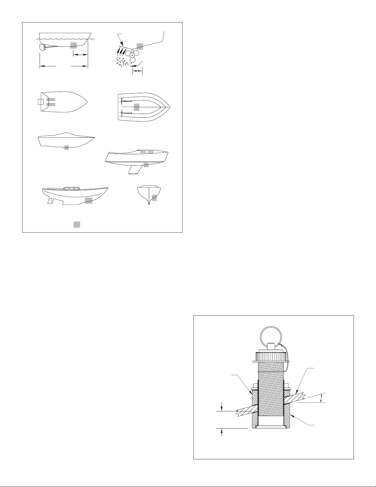
Figure 1.
pressure waves
150- 300 mm
(6-12")
displacement hull
planing hulls
fin keel sailboat
full keel sailboat
inboard
Best location for the transducer
AIRMAR
®
Outboard and I/O —Mount just forward of the engine(s).
Inboard —Mount well ahead of the propeller(s) and shaft(s).
Stepped-hull —Mount just ahead of the first step.
Boat capable of speeds above 25kn (29MPH)—Review the
installation location and operating results of similar boats before
proceeding.
• Fin keel sailboat —Mount to the side of the centerline and
forward of the fin keel 300–600mm (1–2').
• Full keel sailboat —Locate amidships and away from the keel
at the point of minimum deadrise angle.
High-Performance Fairing
• Corrects for the deadrise angle of the hull, so the transducer
beam shoots straight down.
• Mounts the transducer deeper in the water for clean flow over
the transducer’s active surface.
• Long streamlined shape directs the water around the
transducer to minimize drag.
Installation
Cored fiberglass hull —Follow separate instructions on page 5.
Caution : Never use products containing strong solvents such as
acetone because solvents can greatly weaken plastic parts.
Caution : Never pull, carry, or hold the transducer by its cable; this
may sever internal connections.
Hole Drilling—Transducer
Mounting Location
Placement
Choose a location:
•Away from the propeller(s) and shaft(s), other machinery, and
other echosounders to minimize the effect of noise on the
echosounder display. The lower the noise level, the higher the gain
setting that can be used.
• Where the water flowing across the hull is smoothest with a
minimum of bubbles and turbulence (especially at high speeds).
• Where the transducer will be continuously immersed in water.
• Where the transducer beam will be unobstructed by the keel or
propeller shaft(s).
• Where there is a minimum deadrise angle.
• Where there is adequate headroom inside the vessel for the
height of the housing, tightening the nuts, and removing the
insert: 200mm (7-3/4") above the top of the housing.
Caution : Do not mount the transducer:
Near water intake or discharge openings,
Behind strakes, fittings, or hull irregularities,
Behind eroding paint (an indication of turbulence).
Boat Types
• Displacement hull powerboat —Locate 1/3 aft LWL and
150–300mm (6–12") off the centerline on the side of the hull
where the propeller blades are moving downward.
• Planing hull powerboat —Mount well aft, on or near the
centerline, and well inboard of the first set of lifting strakes to
insure that the transducer is in contact with the water at high
speeds. Mount on the side of the hull where the propeller
blades are moving downward.
(see Figure 1)
Warning : Always wear safety goggles and a dust mask.
1. Drill a 3mm or 1/8" pilot hole perpendicular to the waterline from
inside the hull (see Figure 2). If there is a rib, strut, or other hull
irregularity near the selected mounting location, drill from the
outside.
2. Using the 51mm or 2" hole saw, cut a hole from outside the hull.
Be sure to hold the drill plumb, so the hole will be perpendicular
to the water surface.
AIRMAR
aft view
hull
backing block
min. fairing
thickness
13mm (1/2")
slope of hull
deadrise
angle
parallel to
water surface
fairing
Figure 2. Measuring the deadrise angle and fairing thickness
®
2
 Loading...