

Page 1

MARINE RADAR
MODEL1833/1933/1943
Page 2

9-52 Ashihara-cho,9-52 Ashihara-cho,
A
A
*00080918701**00080918701*
*00080918701**00080918701*
*IME35020E00**IME35020E00*
Nishinomiya, JapanNishinomiya, Japan
Telephone :Telephone : 0798-65-21110798-65-2111
Telefax :Telefax : 0798-65-42000798-65-4200
Your Local Agent/DealerYour Local Agent/Dealer
ll rights reserved.
ll rights reserved.
PUB.No.PUB.No. IME-35020-EIME-35020-E
(( HIMAHIMA ))
MODEL1833/1933/1943MODEL1833/1933/1943
Printed in JapanPrinted in Japan
FIRST EDITION :FIRST EDITION : APR.APR. 20012001
E :E : APR.APR. 22,200222,2002
* 0 0 0 8 0 9 1 8 7 0 1 ** 0 0 0 8 0 9 1 8 7 0 1 *
*IME35020E00**IME35020E00*
* I M E 3 5 0 2 0 E 0 0 ** I M E 3 5 0 2 0 E 0 0 *
Page 3
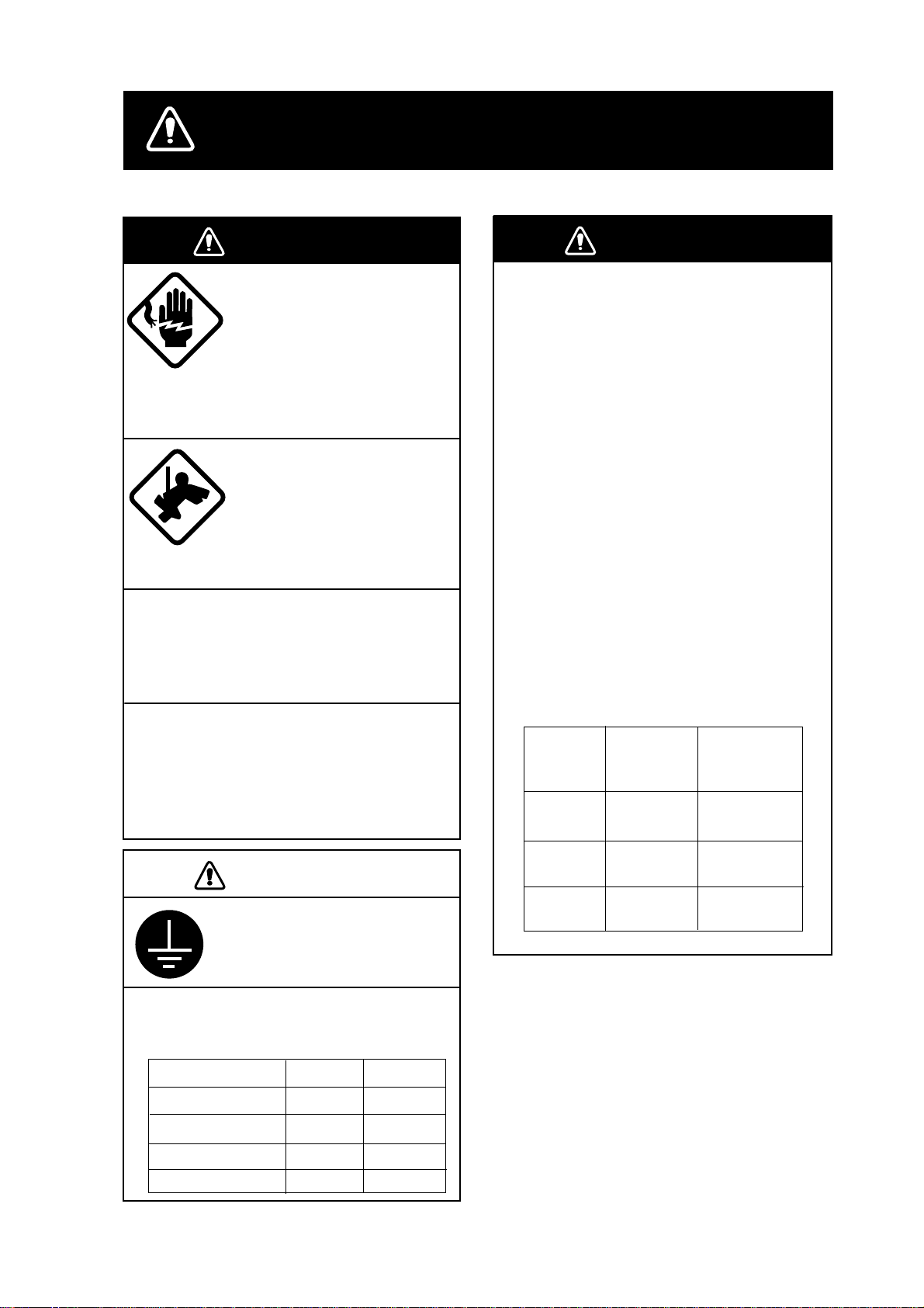
SAFETY INSTRUCTIONS
WARNING
Do not open the equipment
unless totally familiar with
electrical circuits and
service manual.
ELECTRICAL
SHOCK
HAZARD
Construct a suitable service platform
from which to install the antenna unit.
Serious injury or death can result if someone falls from the radar mast.
Turn off the power at the mains switchboard before beginning the installation.
Fire, electrical shock or serious injury can
result if the power is left on or is applied
while the equipment is being installed.
Only qualified personnel
should work inside the
equipment.
Wear a safety belt and hard
hat when working on the
antenna unit.
Serious injury or death can
result if someone falls from
the radar mast.
WARNING
Radio Frequency
Radiation Hazard
The radar antenna emits electromagnetic
radio frequency (RF) energy which can be
harmful, particularly to your eyes. Never
look directly into the antenna aperture from
a close distance while the radar is in
operation or expose yourself to the transmitting antenna at a close distance.
Distances at which RF radiation levels of
100 and 10 W/m
table below.
Note: If the antenna unit is installed at a
close distance in front of the wheel house,
your administration may require halt of
transmission within a certain sector of
antenna revolution. This is possible - Ask
your FURUNO representative or dealer to
provide this feature.
MODEL
1833
2
exist are given in the
Distance to
100 W/m
point
Nil
Distance to
2
10 W/m
Worst case
point
0.50 m
2
CAUTION
Ground the equipment to
prevent electrical shock and
mutual interference.
Observe the following compass safe
distances to prevent deviation of a
magnetic compass.
Display unit
1833 antenna unit
1933 antenna unit
1943 antenna unit
Standard
0.85 m
0.90 m 0.70 m
1.00 m
1.00 m
Steering
0.55 m
0.80 m
0.80 m
1933
1943
Worst case
0.20 m
Nil
Worst case
3.00 m
Worst case
2.50 m
i
Page 4

TABLE OF CONTENTS
SAFETY INSTRUCTIONS........................................................................................i
EQUIPMENT LISTS ................................................................................................. iii
SYSTEM CONFIGURATIONS.................................................................................. v
1. MOUNTING .......................................................................................................... 1-1
1.1 Installation of Display Unit............................................................................................................... 1-1
1.2 Mounting of Antenna Unit for MODEL 1833 ................................................................................... 1-4
1.3 Mounting of Antenna Unit for MODEL 1933/1943 .......................................................................... 1-11
2. W IRING.................................................................................................................2-1
2.1 Standard Wiring..............................................................................................................................2-1
2.2 External Buzzer (OP03-136, option) Connection............................................................................ 2-3
2.3 How to Connect with PC................................................................................................................. 2-4
3. ADJUSTMENT ..................................................................................................... 3-1
3.1 How to Access to Installation Menu................................................................................................ 3-1
3.2 NETWORK SETUP Menu .............................................................................................................. 3-2
3.3 RADAR SETUP Menu .................................................................................................................... 3-4
3.4 Checking Magnetron Heater Voltage..............................................................................................3-10
3.5 Navigation Data Source.................................................................................................................. 3-11
3.6 Setting up Data Ports......................................................................................................................3-15
3.7 Remote Controller Setting............................................................................................................... 3-17
4. OPTIONS..............................................................................................................4-1
4.1 ARP Kit ARP-1 1.............................................................................................................................. 4-1
4.2 Connection of External Monitor/Remote Display............................................................................ 4-3
PACKING LISTS.......................................................................................................A-1
OUTLINE DRAWINGS .............................................................................................D-1
SCHEMATIC DIAGRAMS.........................................................................................S-1
ii
Page 5

EQUIPMENT LISTS
Standard supply
Name Type Code No. Qty Remarks
Display unit RDP-127 - 1
RSB-0071-057 - MODEL 1833
XN10A-RSB-0070-064 - MODEL1933, 24 rpm
Antenna unit
Remote
controller set
Installation
materials
Accessories FP03-09200 000-080-020 1set FP03-09301, FP03-09202,
Spare parts SP03-14001 000-080-018 1set Fuses
XN10A-RSB-0073-064 - MODEL1933, 48 rpm
XN12A-RSB-0070-059 - MODEL1943, 24 rpm
XN12A-RSB-0073-059 -
RMC-100 000-089-885 1
CP03-21900 000-080-019 1set
CP03-16901 008-478-750
CP03-21800 000-080-014 For MODEL1833
CP03-21810 000-080-015 For MODEL1833
CP03-21820 000-080-016 For MODEL1833
CP03-21830 000-080-017
CP03-18401 008-503-360 1set
CP03-22901 008-523-690 1set
CP03-22000 000-080-021
CP03-22010 000-080-022
CP03-22020 000-080-023
CP03-22030 000-080-024
1
1set
1
1
MODEL1943, 48 rpm
Remote controller, vinyl case,
battery, labels
For display unit,
MJ-A3SPF0018-050Z cable,
CP03-21901
For MODEL1833
antenna unit
10 m signal cable
15 m signal cable
20 m signal cable
For MODEL1833
30 m signal cable
For MODEL1933/1943
antenna unit
For MODEL1933/1943
antenna radiator
XN10A/XN12A
For MODEL1933/1943
10 m signal cable
For MODEL1933/1943
15 m signal cable
For MODEL1933/1943
20 m signal cable
For MODEL1933/1943
30 m signal cable
FP03-09203, FP03-09204
iii
Page 6

Optional supply
Name Type Code No. Qty Remarks
Rectifier
External buzzer OP03-136 000-086-443 1
Cable assy.
RGB output
cable kit
Filter FP03-09101 008-523-060 1
ARP kit ARP-11 008-523-050 1 ARP Board
Mounting
bracket (1)
Chart card - - - Specified when ordering.
RAM card 00RAM02MC-004 004-371-790 1 2 MB
Remote
controller set
Modification kit
for C-map
Cable set for
remote display
PR-62
RU-3423 000-030-443 1 For MODEL1933/1943
MJ-A6SPF0014-010 000-144-421 1 For NavNet, 1 m
MJ-A6SPF0014-050 000-144-422 1 For NavNet, 5 m
MJ-A6SPF0014-100 000-144-423 1 For NavNet, 10 m
MJ-A6SPF0014-200 000-144-424 1 For NavNet, 20 m
MJ-A6SPF0014-300 000-144-425 1 For NavNet, 30 m
MJ-A6SPF0012-050 000-134-424 1 For navaid, 5 m
MJ-A6SPF0012-100 000-133-817 1 For navaid, 10 m
MJ-A6SPF0003-050 000-117-603 1 w/6P connector, 5 m
MJ-A6SPF0009-100 000-125-236 1 w/6P connector, 10 m
MJ-A6SPF0007-100 000-125-237 1 For compass, 10 m
MJ-A7SPF0007-050 000-144-418 1
MJ-A6SRMD/TM11AP8-005
OP03-176 008-526-360 1 For external display
OP03-92 008-445-070 1 For MODEL1833
RMC-100 000-089-885 1
MODEL 17*2/C-MAP 008-525-200 1 See modification instruction
OP03-174-5 008-523-000 5 m
OP03-174-10 008-523-010 10 m
OP03-174-15 008-523-020 15 m
OP03-174-20 008-523-030 20 m
OP03-174-30 008-523-040 1 30 m
000-013-484 F or MODEL1833, 100 VAC
000-013-485 F or MODEL1833, 110 VAC
000-013-486 F or MODEL1833, 220 VAC
000-013-487
000-144-463 1 Adapter cable for HUB
1
For MODEL1833, 230 VAC
For external buzzer, PC,
w/7P connector, 5 m
E42-0005-x
iv
Page 7
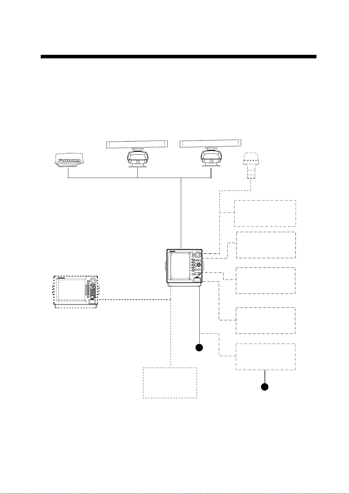
SYSTEM CONFIGURATIONS
The MARINE RADAR MODEL 1833/1933/1943 has IP address to communicate with the
“NavNet” products located within the network, based on the TCP/IP protocol through
Ethernet 10Base-T. A NavNet system may consist of one, two, three or four display unit and
one ETR. For a system incorporating three or more products a “hub” is required to process
data. Simple system such as Figure1 below, or integrated systems Figure 2 are explained.
Antenna Unit
MODEL1833
MODEL1933
Display Unit
RDP-127
MODEL1943
GPS receiver
GP-310B/320B
Echo sounder
Navigator
External buzzer
PC
Echo sounder
VGA monnitor
Remote display
Other NavNet unit
(GD-1900C etc.)
* PR-62: MODEL1833
RU-3423: MODEL1933/1943
Figure 1 Single unit NavNet system
12/24 VDC
Network
sounder
ETR-6/10N
100/110/115/220/230 V AC
1φ, 50/60 Hz
Heading
sensor
Rectifier*
PR-62
RU-3423
Ship's mains
v
Page 8
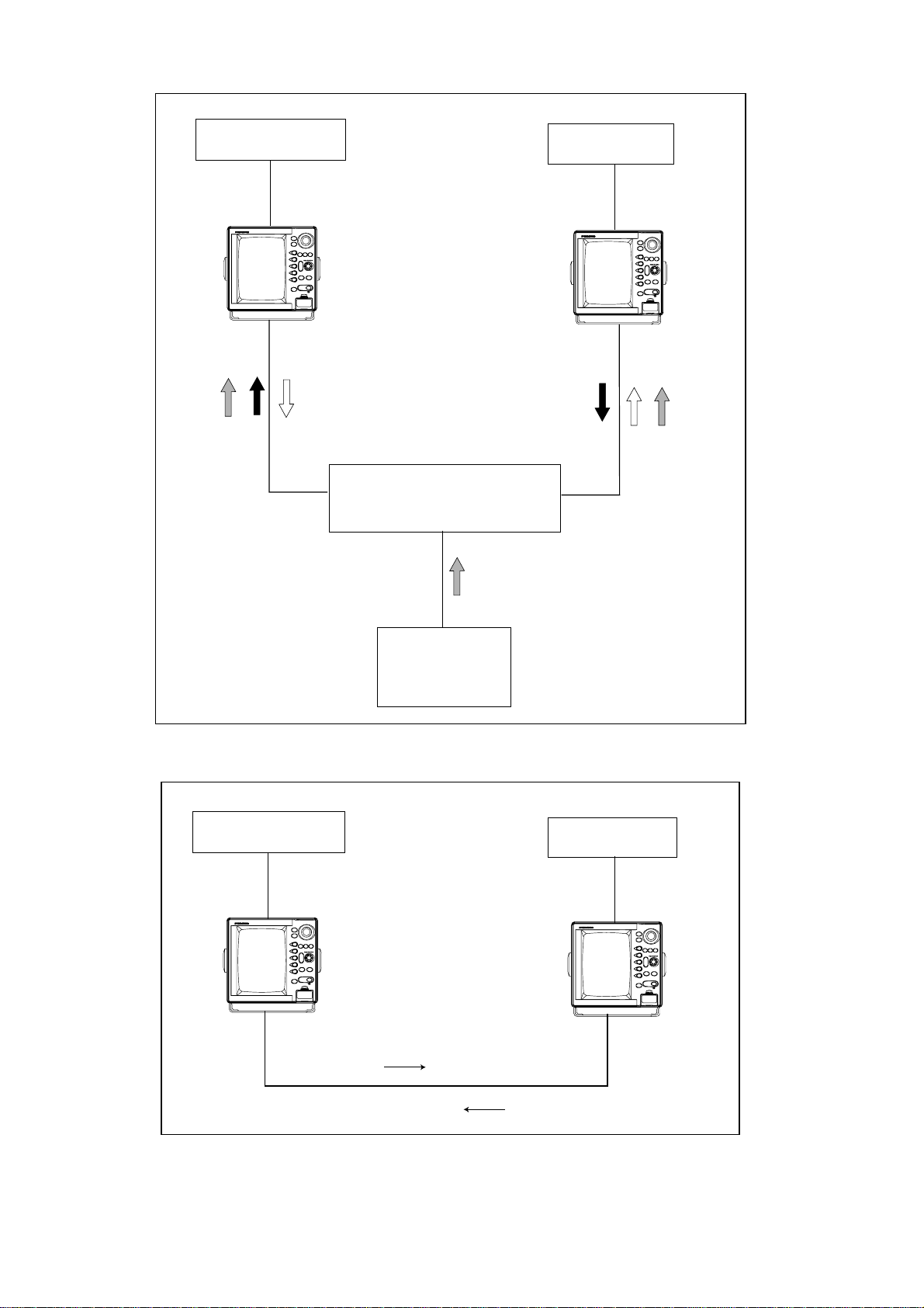
Antenna Unit
GP-310B/320B
Radar data
HUB
Network
Transducer
ETR-6/10N
Plotter data
Sounder data
Figure 2 (a) NavNet system, three-unit connection
Antenna Unit
GP-310B/320B
Radar data
Figure 2 (b) NavNet system, two-unit connection
vi
Plotter data
Page 9
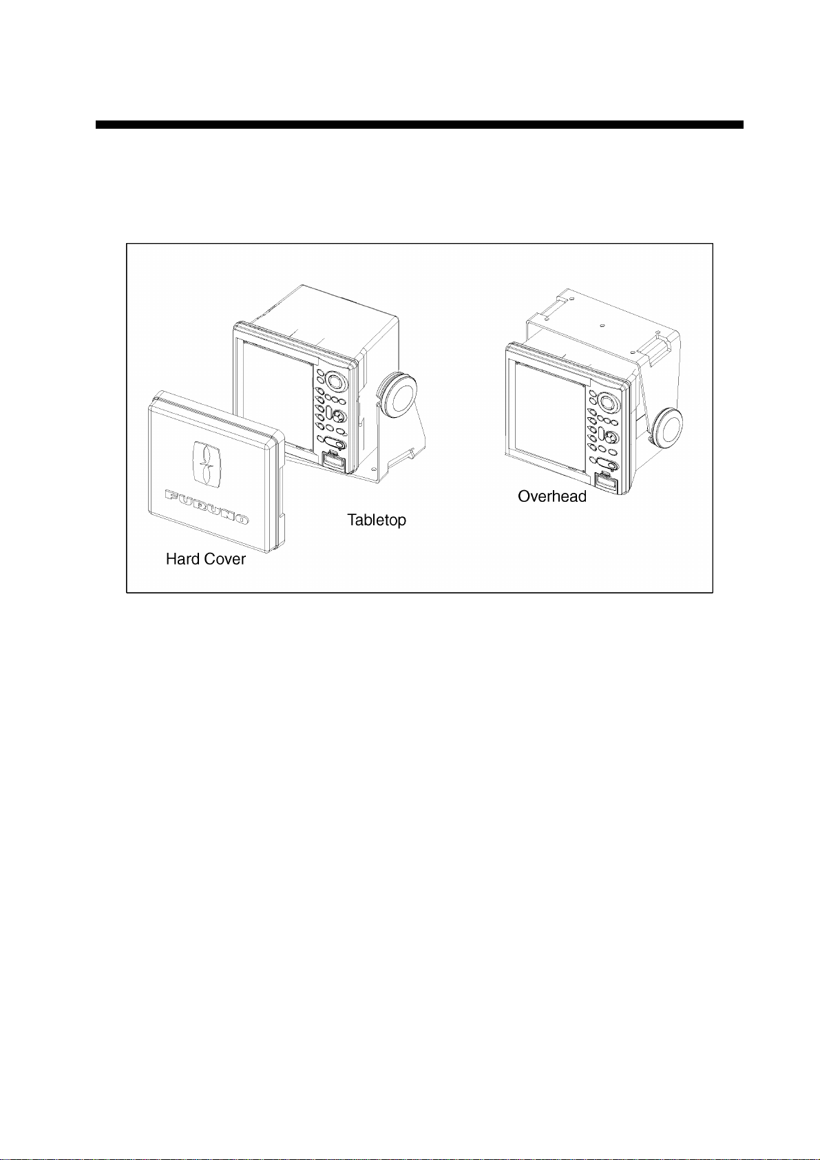
1. MOUNTING
1.1 Installation of Display Unit
The display unit can be installed on a tabletop, on the overhead or flush mounted in a
console or panel.
Tabletop, overhead mounting method
When selecting a mounting location for the display unit keep the following in mind:
Even though the display unit is waterproof, it is recommended that the display unit must
•
be mounted inside an enclosed cabinet.
Keep the display unit out of direct sunlight.
•
The temperature and humidity should be moderate and stable.
•
Locate the unit away from exhaust pipes and vents.
•
The mounting location should be well ventilated.
•
Mount the unit where shock and vibration are minimal. If the mounting location is subject
•
to heavy vibration, fix the display unit to the hanger perpendicular.
Keep the unit away electromagnetic field generating equipment such as motor, generator.
•
For maintenance and checking purposes, leave sufficient space at the sides and rear of
•
the unit and leave slack in cables.
A magnetic compass will be affected if the display units placed too close to the magnet
•
compass. Observe the following compass safe distances to prevent disturbance to the
magnetic compass; standard compass: 0.85 m, steering compass: 0.55 m.
1-1
Page 10
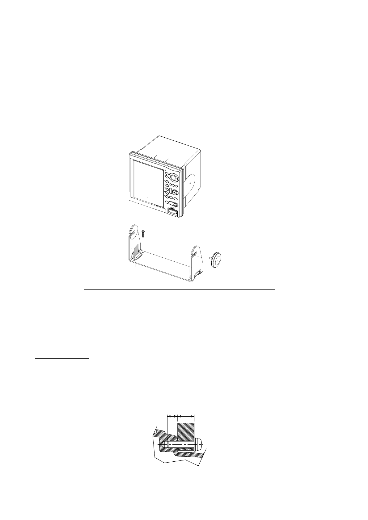
1.1.1 Mounting procedure
Tabletop, overhead mounting
Follow the procedure below to mount the display unit on a tabletop or the overhead.
1. Fix the hanger by f our tapping screw.
2. Screw knob bolts in display unit, set it t o hanger, and tighten knob bolts.
3. Attach hard cover to protect CRT.
Display unit
Tapping screws
(4 pcs.)
Knob bolts (2 pcs.)
Anti-vibration
rubber
Hanger
Tabletop, overhead mounting of display unit
Note: For overhead mounting, reinforce the mounting locat ion and secure the hanger will
bolts, nuts and washers (local supply).
Flush mounting
Note: Use supplied six pan head screws when the thickness of the bulkhead is from 11 to
14 mm. For bulkhead which exceeds 14 mm in thickness the length of the pan head
screws should be bulkhead thickness (A) plus 7.8 ±2 mm. Also the length of B should
be max. 8 mm.
B
A
1-2
Fixing screw, side view
Page 11
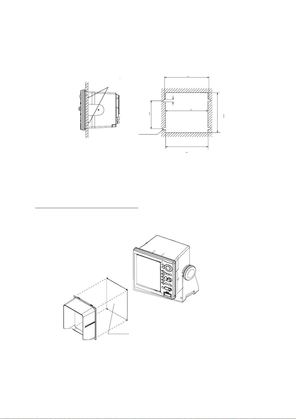
1. Prepare a cutout in the mounting location by using the template sheet supplied as the
installation material.
2. Fix the display unit by f our washer head screws M4x20. Refer to the outline drawing at
back of this manual.
264+0.5
Washer head screws
4.5
258+1
165+0.5
4-R2.25
285+1
243+1
Flush mounting of display unit
Note: When installing the display unit in a panel, attach the vinyl tube (Ф6, local supplied) to
the drain hole at the back of the display unit to allow moisture to escape. Then fasten
the tube to the drain hole with a cable tie.
Attachment of hood and filter (option)
Set four notches of hood to grooves on the display unit. When using the optional filter,
attach the filter to the hood with non-glare side outward, and then set the hood t o the
display unit.
Hood
Display unit
Filter (option)
(FP03-09101: Code no. 008-523-000)
Non-glare side
Attaching of hood and filter (option)
1-3
Page 12
1.2 Mounting of Antenna Unit for MODEL1833
1.2.1 Mounting considerations
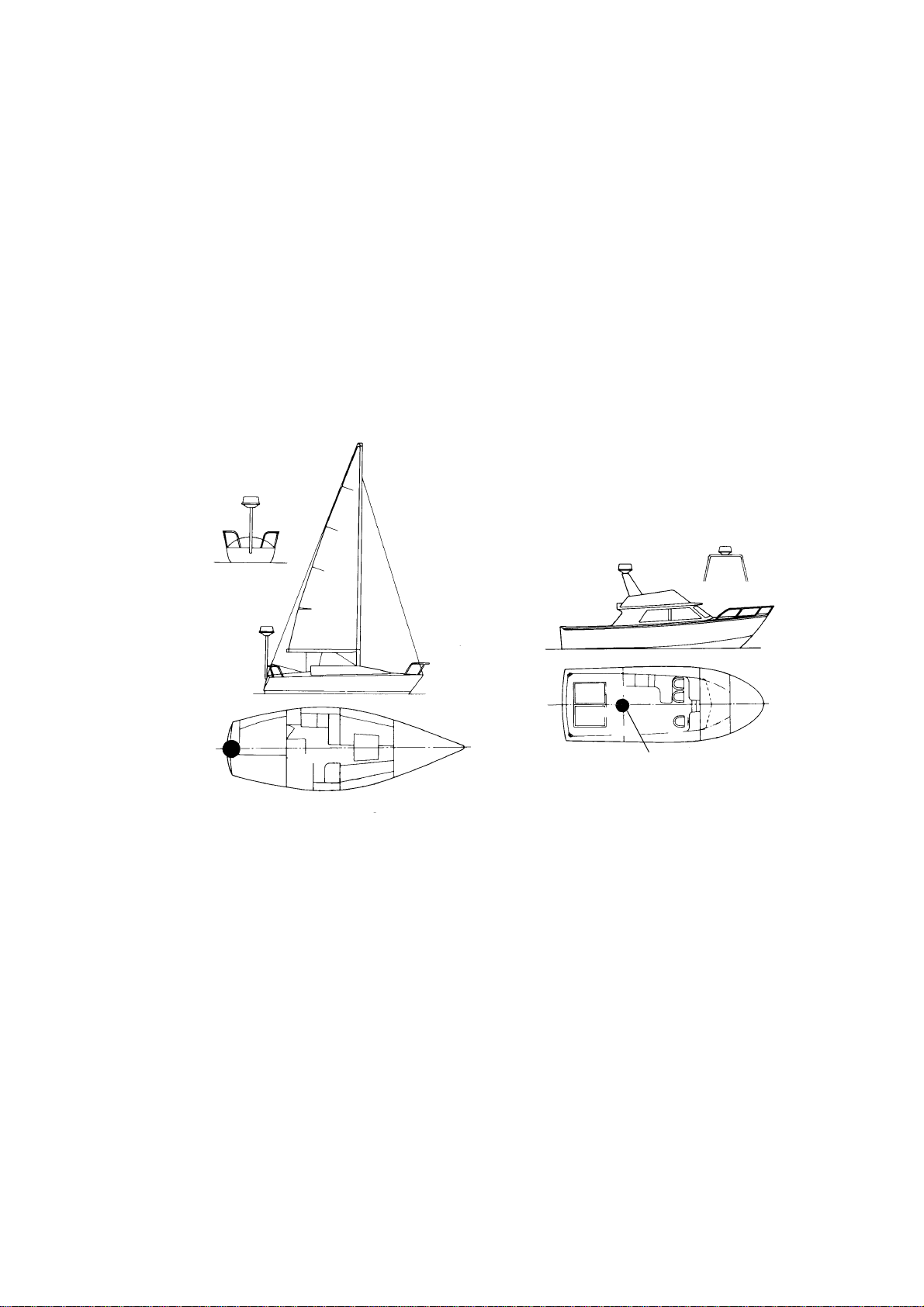
When selecting a mounting location for the antenna unit keep in mind the following points.
Install the antenna unit on the hardtop, radar arch or on a mast on an appropriate
•
platform. (F or sailboats, a mounting bracket is optionally available.) It should be placed
where there is a good all-round view with, as far as possible, no part of the ship’s
superstructure or rigging intercepting the scanning beam. Any obstruction will cause
shadow and blind sectors. A mast, for instance, with a diameter considerably less than
the width of the antenna unit, will cause only a small blind sector. However, a horizontal
spreader or crosstrees in the same horizontal plane would be a much m ore serious
obstruction; place the antenna unit well above or below it.
Antenna unit
Antenna unit
Antenna unit
Typical antenna unit placement on sailboat and powerboat
In order to minim ize the chance of picking up electrical interference, avoid where possible
•
routing the antenna cable near other electrical equipm ent onboard. Also avoid running
the cable in parallel with power cables.
The compass safe distance of 0.90 meters (standard compass) and 0.70 meters (steering
•
compass) should be observed to prevent deviation of the magnetic compass.
Antenna unit
1-4
Page 13
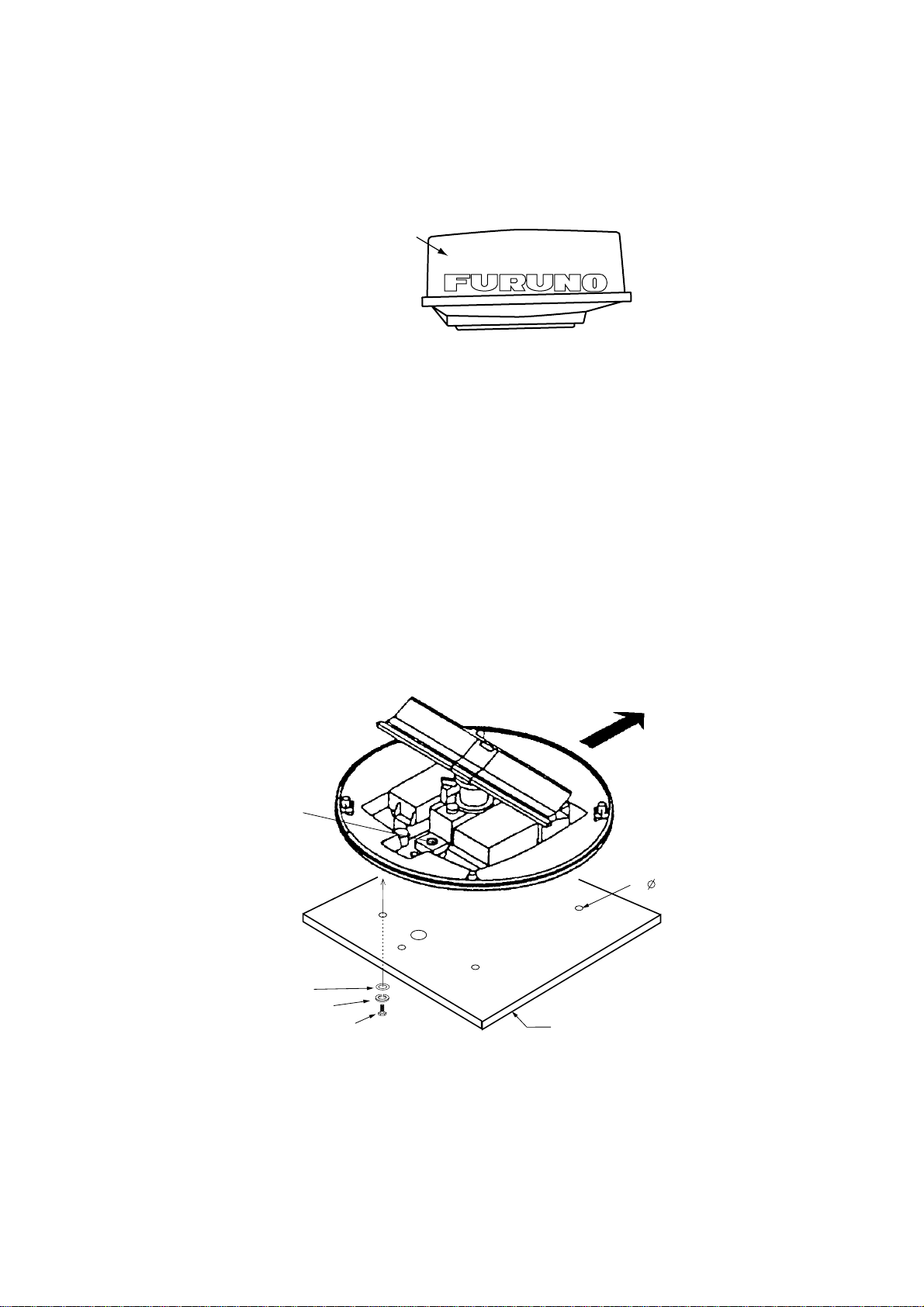
1.2.2 Mounting antenna unit of MODEL 1833
1. Open t he antenna unit packing box carefully.
2. Unbolt t he four bolts at the base of the radome to remove the radome cover.
Radome cover
Antenna unit
The mounting surface must be parallel with the waterline and provided with five holes
whose dimensions are shown in the outline drawing attached at the end of this manual.
The unit is adjusted so a target echo returned from the bow direction will be shown on the
zero degree (heading line) position on the screen. W hen drilling holes, be sure they are
parallel with the fore and aft line.
3. Prepare a platform of 5 to 10 millimeters in thickness for the antenna unit.
A mounting bracket for mounting the antenna unit on a sailboat mast is optionally
available. (Refer to page 1-9.) Find the cable entry on the radome base. Next, position
the radome base so the cable entry faces the stern direction. This alignment must be as
accurate as possible.
Ship's bow
Cable
entry
4- 12 Holes
Flat washer
Spring washer
M10 x 25 Hex bolt
Platform
Antenna unit, cover removed
1-5
Page 14
Antenna base plate
Effective
thread length
25 mm
Flat
washer
Spring
washer
Apply silicone sealant.
M10 x 25
Hex bolt
Gasket
Radome
5 - 10 mm
Platform
How to fasten the radome base to the mounting platform
Wiring and final preparation
4. Drill a hole of at least 20 millimet ers diameter through the deck or bulkhead to run the
signal cable between the antenna unit and the display unit. (To prevent electrical
interference avoid running the signal cable near other electrical equipment and in
parallel with power cables.) Pass the cable through the hole. Then, seal the hole with
sealing compound for waterproofing.
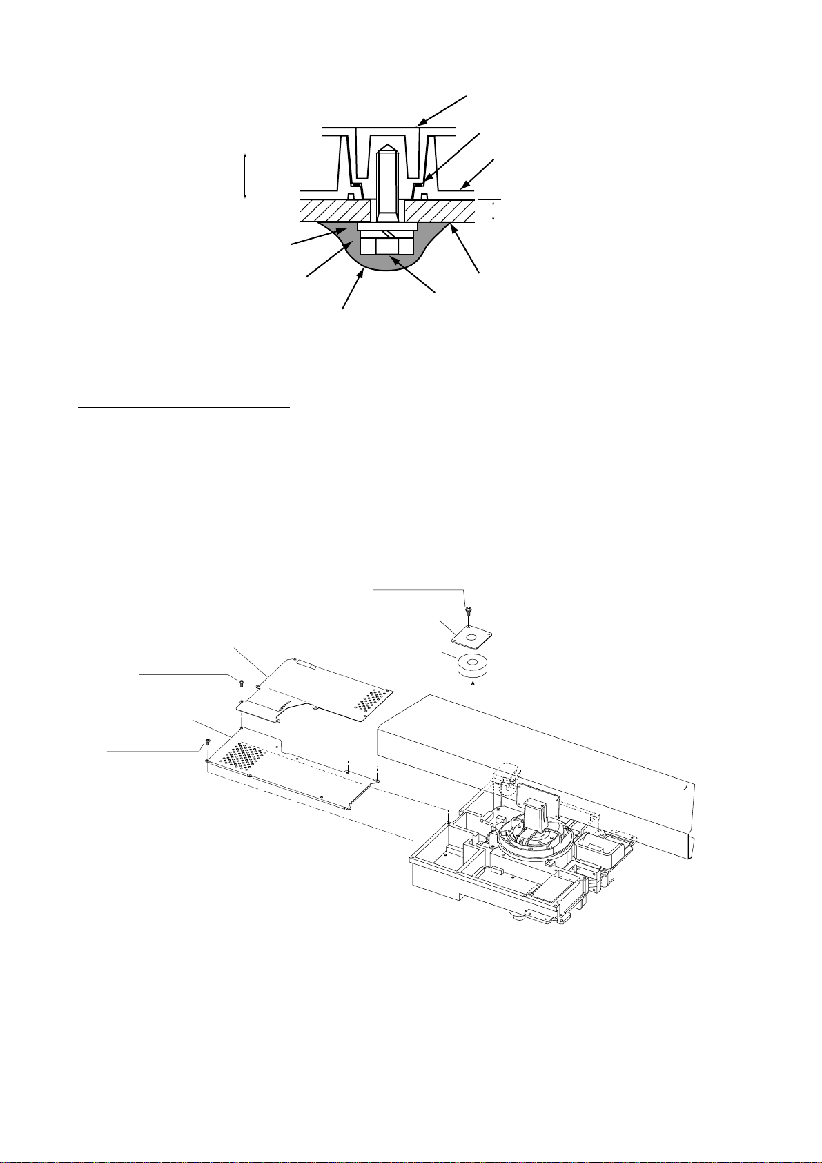
5. Remove two shield covers in the radome.
6. Remove the cable clamping plate by unfastening f our screws and rem oving a gasket.
Pan head screws
M4x8 4 pcs.
Cable clamping plate
Shield cover
Pan head screws
M4x8 7 pcs.
Shield cover
Pan head screws
M4x8 7 pcs.
Gasket
Antenna unit, inside view
7. Pass the cable through the hole at the bottom of the radome base.
8. Secure the cable with the cable clamping plate and gasket. Ground the shield and vinyl
wire by one of the screws of the cable clamping plate.
9. Connect t he wire to the RF unit .
1-6
Page 15
Cable
entry
to one of the screws
of the cable clamping plate
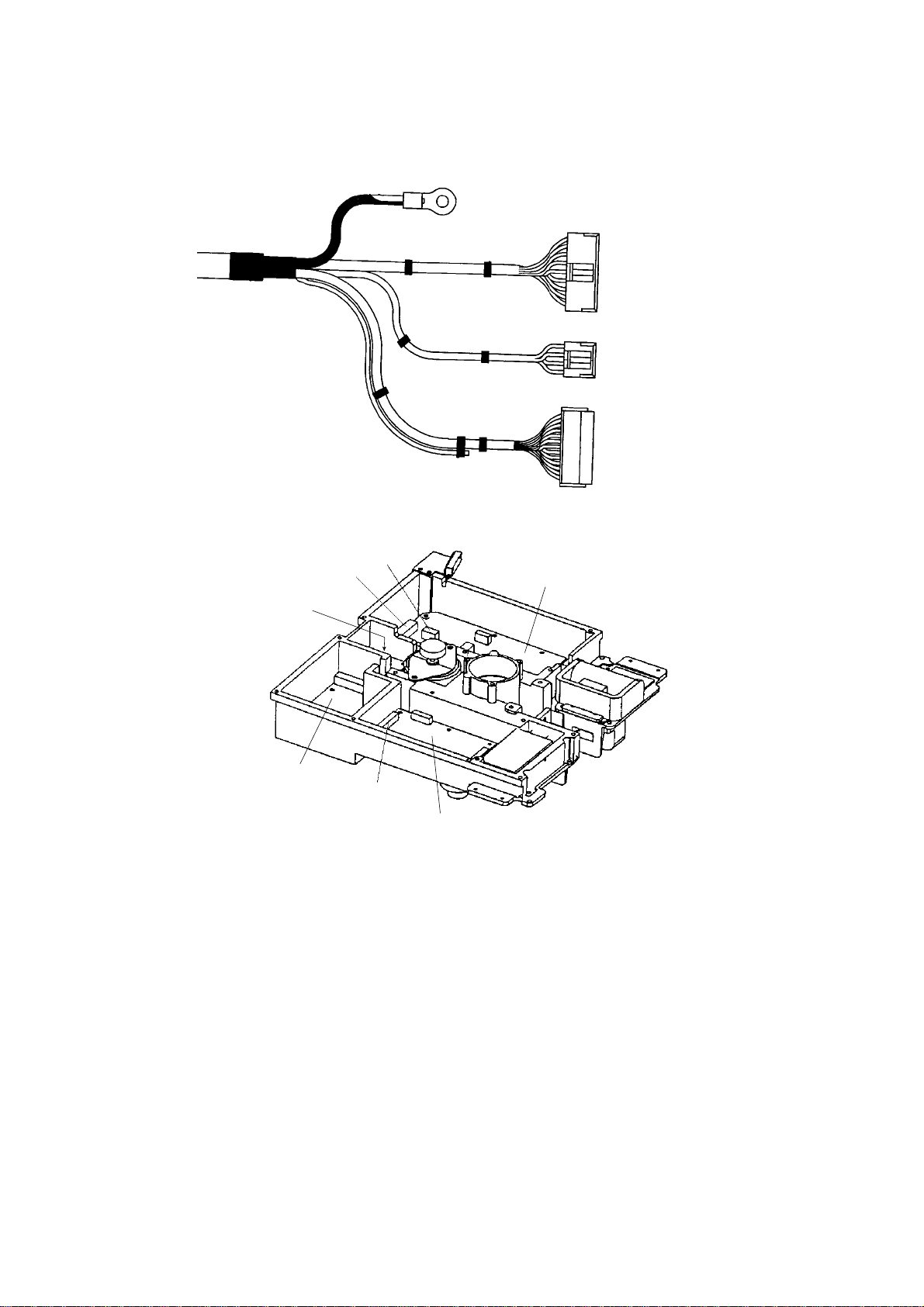
Signal cable, antenna unit side
J802
J801
9-pin connector:
to J801 on MD-9208
4-pin connector:
to J802 on MD-9208
13-pin connector:
to J611 on IF-9214A
MD-9208
PTU-9335
J611
IF-9214
RF unit
1-7
Page 16
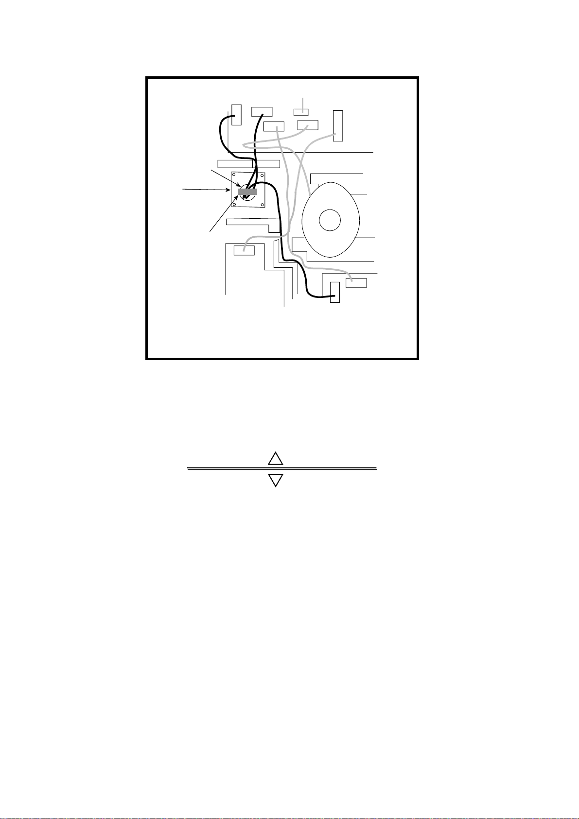
10. Attach the EMC core supplied as shown below.
J801
Cable
entrance
Cable
clamping plate
EMC core
E04SS251512
(Above cable
clamping
plate)
PTU-9335
J1
J802
J804
J805
J803
Motor
J611
MD9208
J806
J613
IF9214IF9214A
How to attach EMC core
11. Fix the shield cover. Do not pinch the cable.
12. Attach the radome cover, aligning triangle mark on radome cover with that on radome
base.
Radome cover
Radome base
How to position the radome cover
13. Loosely fasten the radome f ixing bolts. You will tighten them after confirming magnetron
heater voltage.
1-8
Page 17

1.2.3 Mounting the optional mounting bracket
A mounting bracket for fastening the antenna unit for MODEL1833 to a mast on a sailboat
is optionally available.
Mounting bracket 1
Type: OP03-92
Code No.: 008-445-070
Type Code No. Qty
Hex. bolt M4X12 000-804-725 4
Hex. bolt M8X20 000-805-707 8
Mounting plate 03-018-9001-0 100-206-740 1
Support plate (1) 03-018-9005-0 100-206-780 1
Support plate (2) 03-018-9006-0 100-206-790 1
Bracket (1) 03-018-9002-1 100-206-751 1
Table 1-1 Mounting bracket contents
Bracket (2) 03-018-9003-1 100-206-761 1
Fixing plate 03-018-9004-1 100-206-771 2
Assemble the mount ing bracket and fasten it to a mast. Fasten the antenna unit to the
bracket.
1-9
Page 18
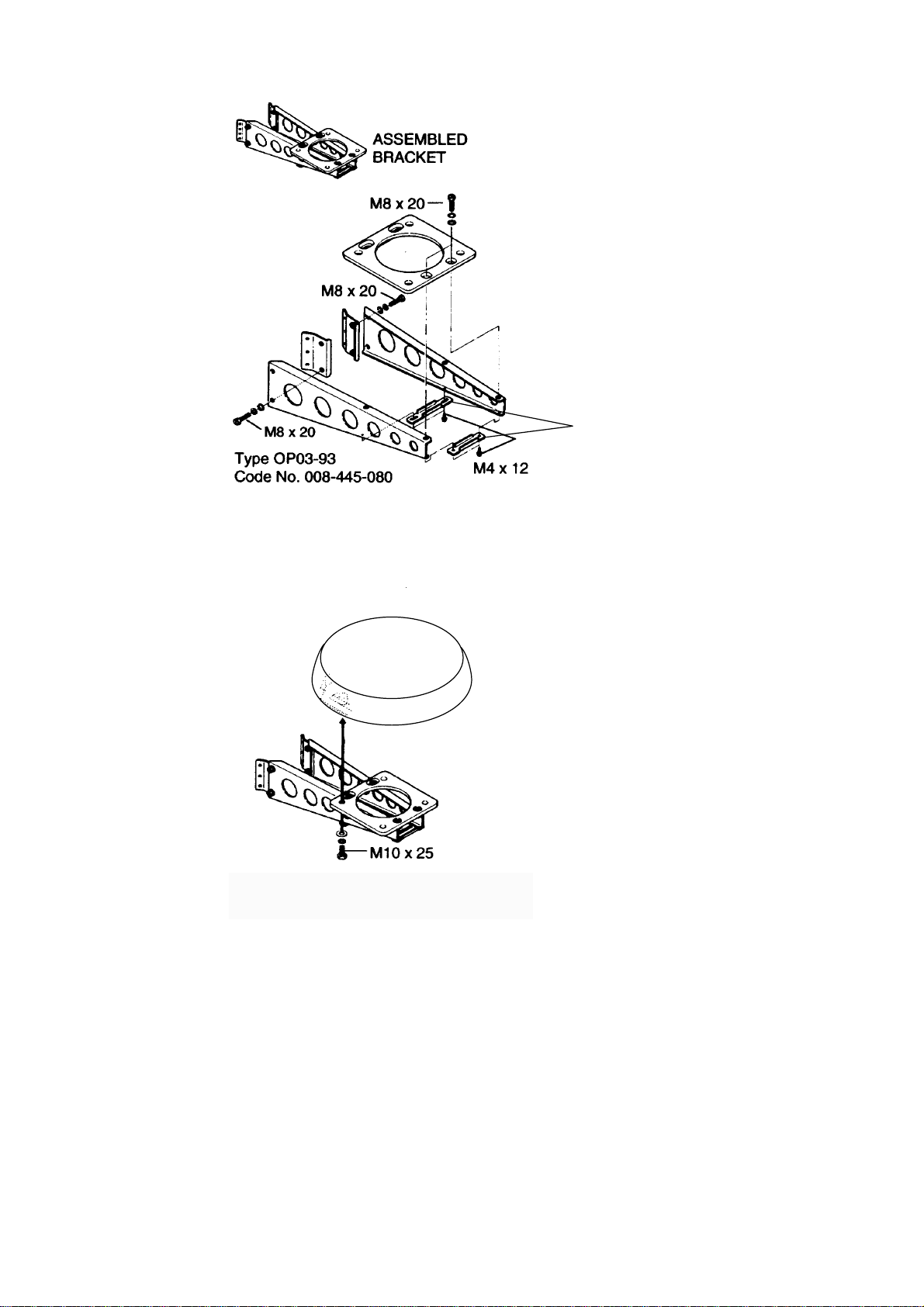
(A) Assembling the mounting bracket
Support plate
(B) Fastening antenna to mounting
bracket
How to assemble and mount the optional mounting bracket
1-10
Page 19

1.3 Mounting of Antenna Unit for MODEL1933/1943
1.3.1 Mounting considerations
The antenna unit is generally installed either on top of the wheelhouse or on the radar
•
mast on a suitable platf orm. Locate the antenna unit where there is a good all-round view.
Any obstruction will cause shadow and blind sectors.
A mast for instance, with a diameter considerably less than the width of the radiator, will
cause only a small blind sector, but a horizontal spreader or crosstrees in the same
horizontal plane as the antenna unit would be a much more serious obstruction; you
would need to place the antenna unit well above or below it.
It is rarely possible to place the antenna unit where a completely clear view in all
•
directions is available. Thus, you should determine the angular width and relative bearing
of any shadow sectors for their influence on the radar at the first opportunity after fitting.
If you have a radio direction finder on your boat, locate its antenna clear of the antenna
•
unit to prevent interference to the direction finder. A separation of more than two meters
is recommended.
To lessen the chance of picking up electrical interference, avoid where possible routing
•
the signal cable near other onboard electrical equipment. Also avoid running the cable in
parallel with power cables.
A magnetic compass will be affected if the antenna unit is placed too close to the antenna
•
unit. Observe the following compass safe distances to prevent deviation of a magnetic
compass: Standard com pass, 1.00 m, Steering compass, 0.80 m.
Do not paint the radiator aperture, to ensure proper emission of the radar waves.
•
When this radar is t o be inst alled on larger vessels, consider the following points:
•
The signal cable run between the antenna and the display comes in lengths of 10 m, 15
•
m, 20 m and 30 m. Whatever length is used it must be unbroken; namely, no splicing
allowed.
Deposits and fumes from a funnel or other exhaust vent can adversely affect the aerial
•
performance and hot gases may distort the radiator portion. The antenna unit must not be
mounted where the temperature is more than 70°C.
As shown in the figure below, the antenna unit may be installed on t he bridge, on a common
mast or on the radar mast.
(a) On bridge
(b) Common mast
(c) Radar mast
1-11
Page 20
1.3.2 Mounting antenna unit of MODEL 1933/1943
Referring to the outline drawing at the back of this manual, drill five holes in the mount ing
platform: four holes of 15 mm diameter for fixing the antenna unit and one hole of 25-30 mm
diameter for the signal cable.
Fastening the Radiator to the Radiator Bracket
For your reference, antenna installation m aterials list appears in the packing lists at the
back of this manual (see page A-4 to A-6).
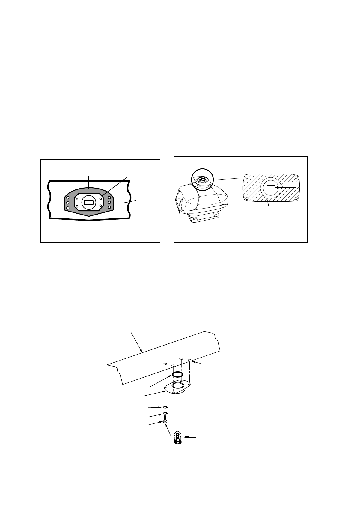
1. Remove the radiator cap from the radiator bracket.
2. Coat contacting surface between antenna radiator and radiator bracket with silicone
sealant as shown in figure below.
ANTENNA RADIATOR
(bottom view)
Coat hatched area with
silicone sealant.
(MODEL 1933)
Groove
Radiator
(MODEL 1943)
RADIATOR BRACKET
(top view)
10mm
Coat hatched area with
anticorrosive sealant.
Coating the bottom of antenna radiator with silicone sealant
3. Coat threaded holes on the antenna radiator with silicone sealant.
4. Grease t he O-ring and set it to the radiator bracket.
5. Lay the antenna radiator on the radiator bracket.
6. Coat the radiator fixing bolts (4 pcs.) with silicone sealant. Fasten the antenna radiator to
the radiator bracket with the radiator fixing bolts, flat washers and spring washers.
Antenna
radiator
1-12
Coat threaded
holes with silicone
sealant.
O-ring
Radiator bracket
Flat washer
Spring washer
Hex head bolt
(M8 x 30)
Coat bolts with
silicone sealant.
Fastening the radiator bracket to the antenna unit chassis
Page 21

Mounting of antenna unit
The antenna unit can be mounted using t he fixing holes on the outside (200 x 200 mm) or
inside (140 x 150 mm) the ant enna unit.
Outside fixing holes
Use the hex head bolt (supplied) to mount the ant enna unit as below.
1. Lay the corrosion-proof rubber mat (supplied) on the mounting platform.
Ground
terminal
Rubber
mat
Bow mark
Location of rubber mat
2. Lay the antenna unit on the mounting platform, orienting it as shown in below.
BOW
STERN
Antenna unit
CAUTION
Do not lift the Antenna unit by the
radiator; lift it by the housing.
The radiator may be damaged.
3. Insert four hex bolts (M12x60, supplied) and seal washers (Ф30, supplied) from the top
of the antenna housing. Insert the seal washers with the larger diameter next t o the bolt
heads. Be sure the seal washer, not other washers, is next to bolt head.
1-13
Page 22

Hex bolt
Seal washer
Flat washer
Spring washer
Nut
Fixing the antenna unit chassis
4. Pass f lat washers (M12, supplied), spring washers (M12, supplied) and nuts (M12,
supplied) onto hex bolts. Fasten by tightening nuts. Do not fasten by tightening the hex
bolts; seal washers may be damaged.
Seal washer
Antenna
Rubber mat
unit
Mounting
platform
Flat washer
Silicone
sealant
How to fasten antenna unit to mounting platform
5. Coat flat washers, spring washers, nuts and exposed parts of bolts with silicone sealant.
6. Prepare ground point in mounting platform (within 300 mm of ground terminal on
antenna unit) using M6 x 25 bolt, nut and flat washer (supplied).
7. Run the ground wire (RW - 4747, 340 mm, supplied) between the ground terminal and
ground point.
8. Coat ground terminal and ground point with silicone sealant as shown on the next page.
1-14
Page 23

Hex bolt
Flat washer
Ground
terminal
Silicone
sealant
Ground
wire
GROUND
TERMINAL
OR
Weld here.
Flat washer
Spring washer
Hex nut
GROUND
POINT
Hex nut
Spring washer
Flat washer
Hex nut
Silicone
sealant
Ground
wire
antenna
unit
How to coat ground point and ground terminal with silicone sealant
1-15
Page 24

Fixing holes inside antenna unit
This method requires rem oval of the RF unit in the antenna unit to access inside fixing
holes. Use hex head bolts, flat washers, spring washers and nuts (local supply) to mount
the antenna unit, confirming length of bolts.
1. Loose four scanner bolts to open the antenna unit. Refer to figure in below for location.
Antenna unit chassis, upper chassis separated
2. Unplug connector connected bet ween upper and lower chassis.
3. Separate upper chassis from lower chassis by removing two hex head bolts (M8x25).
4. Remove cover by unfastening four pan head screws.
5. Remove connector from RF unit.
6. Remove RF unit by unfastening four hex head bolts.
7. Lay the corrosion-proof rubber mat (supplied) on the mounting platform.
8. Fasten the lower chassis to the mounting platform with hex head bolts, spring washers,
flat washers and nuts (local supply), and then coat flat washers, nuts and exposed parts
of bolts with silicone sealant. Cut a slit in rubber bushing and insert bolt into bushing. Do
not use seal washers.
9. Reassemble RF unit, cover and chassis.
10. Set four knob caps (supplied) into outside fixing holes.
11. Do steps 6-8 in “Outside fixing holes”.
1-16
Page 25

2. WIRING
2.1 Standard Wiring
All wiring are terminated at the rear of the display unit.
Optional cable
(Remote display
and external monitor)
Drain hole
(Allows moisture
to escape.)
Power cable
connector
Connect power
cable here.
Signal cable
(to antenna unit)
Ground terminal
Connect ground wire between
here and ship's ground.
CAUTION
CAUTION
Replace fuse to 7 A
when the ship's battery
is 24 VDC, and attach
a label to the fuse cover
on power cable.
The unit is shipped
with 15 A fuse.
Use of wrong fuse can
result in damage to the
equipment.
NETWORK
NavNet
equipment
(GD-1900C,
ETR-6/10N,
HUB etc.)
(6P)
DATA3
Ext. buzzer/
PC (7P)
Display unit, rear view
Ground the
equipment to
prevent
interference.
DATA2
Heading
sensor (6P)
(AD or
NMEA)
DATA1
GPS sensor
GPS-310B,
320B/NMEA
equipment
(7P)
2-1
Page 26

Power cable
Connect the power cable to the POWER connector.
Signal cable connection (from the antenna unit)
Connect the signal cable to SIGNAL connector.
Ground terminal
Connect the ground wire (local supply, IV-2sq) between the ground term inal and ship’s
ground.
DATA1 to DATA3
Other equipments can be connected here as shown below.
DATA1 (7P) DATA2 (6P) DATA3 (7P)
NMEA (IN/OUT)
GPS sensor GPS-310B/320B,
Navaid, sounder etc.
Heading sensor
(ex. SC-60/120)
NMEA IN, NMEA OUT for PC
External buzzer
PC
This equipment can receive the following NMEA 0183 format sentence from an other
equipment.
• Own ship’s position: GGA>RMC>RMA> G LL
• Ship’s speed: RMC>RMA>VTG> VHW
• External waypoint: RMB>WPL>BWR>BWC
• Heading (True): HDT>HDG>HDM
• Course: RMC>RMA>VTG
• Depth: DPT>DBT
• Temperature: MTW
• Time: ZDA
• Other ship’s information: TTM
• Insight satellite information: GSV
• Target L/L TLL
You will need the optional NMEA cable to connect with other equipment.
2-2
Page 27

NETWORK port
Other NavNet equipment should be connect ed to this port with the optional NavNet cable.
Available equipment are shown below.
Radar Plotter Transducer Other
MODEL1722/1732/
1742/1762/1722C/
1732C/1742C/1762C/1752C
1833/1933/1943/
1833C/1933C/1943C/1953C
GD1700/1700C/1900C ETR-6/10N
HUB (used when more
than two NavNet unit s
are connected.)
2.2 External Buzzer (OP03-136, option) Co nnection
The optional external buzzer provides a louder alert when the guard alarm is violated.
External buzzer
Type: OP03-136
Code no.: 000-096-443
Further, you need the optional cable assy MJ-A7SPF0007-050 (w/7P connector, 5 m, code
no. 000-144-418).
1. Attach the MJ-A7SPF0007-050 cable assy (option) to the DATA 3 port at the rear of the
display unit.
2. Cut the XH connector at the end of the external buzzer cable with appropriate length.
3. Solder the cables made at step 2 with MJ-A7SPF0007-050 cable as shown below.
Red
Soldering
External buzzer
Black
Cut other cables off, and wrap here with tape.
MJ-A7SPF0007-050
Connection of external buzzer and display unit
using cable assy type MJ-A7SPF0007-050 cable
4. Fasten the buzzer with the double-sided tape or t wo tapping screws (3x15 or 3x20, local
supply).
2-3
Page 28

2.3 How to Connect with PC
When connecting with the personal computer, prepare the optional cable assy
MJ-A7SPF0007-050 and D-sub 9 pins plug (local supply), and connect them as follows.
SHIELD
BLUE
WHITE
5
1
69
D-SUB 9PIN
RI
1
2
3
4
5
6
7
8
9
CD
RD
TD
DTR
GND
DSR
RTS
CTS
WHITE
BLUE
SHIELD
short
MJ-A7SPF0007-050
1
TD
2
RD
3
RD_A
4
RD_B
5
+12V
6
EXT BUZZ
7
GND
MJ-A7SPF0007-050 cable connection for PC
2-4
Page 29

3. ADJUSTMENT
3.1 How to Access to Installation Menu
You should do the set up for the equipment t hrough the installation menu when installation
has been finished. To access to the installation menu, follow the steps in below.
1. Press the [P OWER/BRILL] key with touch-and-release action while pressing the [MENU]
key down. You hear a beep sound.
2. Releas e t he [MENU] key when the message of “STARTING INSTALLATION MODE”
appears.
3. After the radar display appears, press the [MENU] key followed by SYSTEM
CONFIGURATION soft key to display the SYSTEM CONFIG menu.
4. Press the INSTALLATION SETUP soft key to display the INSTALL SETUP menu.
RADAR
MENU
RADAR DISPLAY SETUP
RADAR RANGE SETUP
ARP SETUP
FUNCTION KEY SETUP
SYSTEM CONFIGURATION
Start up display
GENERAL SETUP
NAV OPTION
SYSTEM SETUP
INSTALLATION SETUP
System configuration menu
SYSTEM
CONFIG
NETWORK SETUP
RADAR SETUP
NETWORK SOUNDER SETUP*
RETURN
*: Do not change settings in this menu.
Install setup menu
How to access the Installation menu
Note: The very first time the system is powered you are asked if you want to start the
simulation mode, which provides simulated operation of the equipment. Press the
[CLEAR] key to start normal operation for radar adjustment. For further details about
the simulation mode, see the operator’s manual.
INSTALL
SETUP
RETURN
START
SIMULATION MODE?
YES ... PUSH ENTER KNOB
NO ... PUSH CLEAR KEY
TO SKIP.
Simulation mode window
3-1
Page 30

3.2 NETWORK SETUP Menu
To communicate with other NavNet equipment, this setting should be done.
1. Open t he INSTALL SETUP menu.
2. Press the NETWORK SETUP soft key.
▲
IP ADDRESS
172.031.003.002
HOST NAME
RADAR________
RADAR SOURCE
NETWORK
SETUP
EDIT
RADAR________
CHART SOURCE
______________
______________
______________
SOUNDER SOURCE
SOUNDER_____
SUBNET MASK
255.255.000.000
GATEWAY ADDRESS
RETURN
000.000.000.000
OFFSET PORT NUMBER
10000
NavNet SETUP menu
3. Select menu option and press the [ENTER] knob or EDIT soft key. For example, select
HOST NAME.
HOST NAME
R A D A R _ _ _
Host name window
4. Use the tr ackball or [ENTER] knob to select location and rotate the [ENTER] knob to set
character (or value).
5. Press the [E NTER] knob or ENTER soft key to finish.
6. Repeat steps 3-5 f or other items.
7. Press the [MENU] key to finish.
8. Continue next setup.
3-2
Page 31

Contents of Network setup menu
Item Description Default Setting
IP ADDRESS This address is assigned at the factory. Change
the address (last three digits; 001 t o 254) when
like models are connected directly or through the
hub. Do this change before connecting the
equipment to the other eq uipment or hub to
distinguish. Do not set the same IP address in the
network.
HOST NAME Set the name for your display unit to distinguish it
from others in the NavNet system. Confirm that
two equipment don’t hav e same host names. The
host name has been preset depending on the
series of NavNet. See the table in below. This host
name is used for RADAR SOURCE and CHART
SOURCE.
RADAR SOURCE Enter the host name “RADAR (preset)” or the new
name set at HOST NAME item setting if the unit
has been changed of the networ k radar to use for
the radar display.
172.031.003.002
RADAR
RADAR
CHART SO URCE Enter a host name (set at HOST NAME) of
network display unit to select equipment which has
chart card in its slot (Max. three un its, excluding
own) to use.
SOUNDER
SOURCE
SUBNET MASK 255.255.000.000
GATEWAY
ADDRESS
OFFSET POR T
NUMBER
The host name of the network sounder ETR-6/10N
is preset (SOUNDER) to use for the video sounder
display. Clear the host name when no network
sounder is connected.
Not used. Reserved for future use.
None
SOUNDER
000.000.000.000
10000
NavNet equipment default sett i ngs
Model IP ADDRESS HOST NAME
MODEL1722/1732/1742/1762 172.031.003.004 RADAR
MODEL1722C/1732C/1742C/1762C/1752C 172.031.003.001 RADAR
MODEL1833/1933/1943 172.031.003.002 RADAR
MODEL1833C/1933C/1943C/1953C 172.031.003.003 RADAR
GD-1700/1700C 172.031.014.001 PLOTTER
GD-1900C 172.031.003.003 PLOTTER
3-3
Page 32

3.3 RADAR SETUP Menu
After the network setup, do the following in order to adjust the radar.
Open the INSTALL SETUP menu, and then press the RADAR SETUP soft key to display
the RADAR SETUP menu. When the message of “RADAR DOES NOT TRANSMIT.
TRANSMIT RADAR?” appears, press the [ENTER] knob to transmit or [CLEAR] key to
cancel transmitting.
▲
ANTENNA TYPE
B
HEADING DATA
MAGNETIC
ANTENNA ROTATION*
ROTATE
TUNING
OFF
TIMING ADJUST
OFF
VIDEO ADJUST
OFF
M.B. SUPPRESSION
OFF
RADAR ANTENN HEIGHT
MEDIUM
STC CURVE
NORMAL
*: Do not change this item setting.
Page 1
RADAR
SETUP
EDIT
NEXT
PAGE
RETURN
Radar setup menu
▲
HEADING ADJUST
OFF
TOTAL ON TIME
000000.0 h
TO TAL TX TIME
000000.0 h
GUARD EXTERNAL BUZZER
OFF
Page 2
RADAR
SETUP
EDIT
PREV.
PAGE
3.3.1 ANTENNA TYPE
Select the antenna type connecting with your di splay unit. Default setting is B.
If necessary, reselect the antenna type referring to the table shown below.
After selection, press the [ENTER] knob or ENTER soft key.
Your unit Setting
MODEL1833 B
MODEL1933 F
MODEL1943 G
3-4
Page 33

3.3.2 TUNING
Initialize the tuning as follows.
1. Transmit the radar
2. Open t he RADAR SETUP menu, and then select TUNING by the trackball or [ENTER]
knob.
3. Press the EDIT soft key or [ENTER] knob to show the setting window.
TUNING
ON
OFF
Tuning setup menu
4. Select ON.
5. Press the [ ENTER] knob or ENTER soft key to start the auto tuning.
6. After the adjustment is completed, the message of “NOW TUNING” disappears.
7. The equipment returns to the menu display automatically.
3.3.3 TIMING ADJUST
This adjustment ensures proper radar performance, especially on short ranges. The radar
measures the time required for a transmitted echo to travel to the target and return to the
source. The received echo appears on the display based on this time. Thus, at the instant
the transmitter is fired, the s weep should start from the center of the display (sometimes
called sweep origin.)
A trigger pulse generated in the display unit goes to the antenna unit through the signal
cable to trigger the transmitter (magnetron). The time taken by the signal to travel up to the
antenna unit varies, depending largely on the length of signal cable. During this period the
display unit should wait before starting the sweep. When the display unit is not adjusted
correctly, the echoes from a straight local object (for example, a harbor wall or straight pier)
will not appear with straight edges – namely, they will be seen as “pushed out” or “pulled in”
near the picture center. The range of objects will also be incorrectly shown.
(1) Target
pulled
(2) Correct
(3) T arget pushed
outward
Examples of improper and correct sweep timing
1. Transmit on the shortest range and confirm that gain and A/C SEA are properly
adjusted.
2. Visually select a target which form s straight line (harbor wall, straight piers).
3. Open the RADAR SETUP menu and select TIMING ADJUST.
3-5
Page 34

4. Press the EDIT key or [ENTER] key to show the setting window.
TIMING ADJUST
ON
OFF
Timing adjust setting menu
5. Select ON and press the [ENT ER] knob or ENTER soft key t o show the radar display.
RETURN
PUSH ENTER KNOB AFTER
ADJUSTING SWEEP TIMING.
Timing adjustment setting display
6. Rotate the [ENTER] knob to straighten the target selected at step 2, and t hen press the
RETURN soft key to finish.
3.3.4 VIDEO ADJUSTMENT
Adjusts video amplifier input level.
1. Open the RADAR SETUP menu and select VIDEO ADJUST by the trackball or [ENTER]
knob.
2. Press the EDIT soft key or [ENTER] knob to show the setting window.
VIDEO ADJUST
ON
OFF
Video adjustment setting window
3. Select ON.
4. Press the [E NTER] key or ENTER soft key to start video adjustment.
5. When adjustment is completed, the message of “NOW ADJUSTING VIDEO” disappears,
and return to the menu display autom atically.
3-6
Page 35

3.3.5 HEADING ADJUST
You have mounted the antenna unit facing st raight ahead in the direction of the bow.
Therefore, a small but conspicuous target dead ahead visually should appear on the
heading line (zero degrees).
In practice, you will probably observe some small error on the display because of the
difficulty in achieving accurate initial positioning of the antenna unit. The follo wing
adjustment will compensate for this error.
1. Set ship’s heading to ward a suitable target (for example, ship or buoy) at a range
between 0.125 and 0.25 nautical mile.
2. Open the RADAR SETUP menu, and press the NEXT PAGE soft key.
3. Select HEADING ADJUST and press the EDIT soft key or [ENTER] knob to show the
HEADING ADJUST window .
4. Select ON followed by [ENTER] key or ENTER soft key to show the radar display.
SET
RETURN
PUSH SOFTKEY 'SET' AFTER
ADJUSTING HEADING LINE.
Heading adjustment setting display
5. Rotate the [ENTER] knob to bisect the target with the EBL.
6. Press the SET soft key.
7. As a final test, move the boat towards a small buoy and confirm that t he buoy shows up
dead ahead on the radar when it is visually dead ahead.
3-7
Page 36

3.3.6 M. B. (Main Bang) SUPPRESSION
Main bang (black hole), which appears at the display center on short ranges, can
suppressed as follows.
1. Open the RADAR SETUP menu and select M.B. SUPPRESSION by trackball.
2. Press the EDIT soft key or [ENTER] knob to show the setting window.
3. Select ON.
4. Press the [ E NTER] knob or ENTER soft key to start video adjustment.
RETURN
M.B. SUPPRESSION
0
Main bung suppression setting window
5. Rotate the [ENTER] knob to suppress main bang (between 0 and 25).
6. Press the RETURN soft key.
3.3.7 RADAR ANTENNA HEIGHT
The A/C SEA function is affected by the antenna height above the waterline. Enter antenna
height above the waterline to optimize the A/C SEA function.
1. Open t he RADAR SETUP menu and select RADAR ANTENNA HEIGHT.
2. Press the EDIT soft key or [ENTER] knob to show the setting window.
RADAR ANT. HEIGHT
HIGH
MEDIUM
LOW
Radar antenna height setting windo w
3. Select ant enna height above the waterline; HIGH (6-10 m ) , MIDIUM (3-6 m) or LOW
(0-3 m). The default setting is MEDIUM.
4. Press the [ENTER] key or ENTER soft key to finish.
3-8
Page 37

3.3.8 STC CURVE
The default STC curve can be maintained in most cases. If necessary the STC curve can
be changed as follows:
1. Open the RADAR SETUP menu and select STC CURVE.
2. Press the EDIT soft key or [ENTER] knob to show the setting window.
RETURN
STC CURVE
NARROW
NORMAL
WIDE
STC curve setting window
3. Select STC curve;
NARROW: The effective range of the [ A/ C S EA] adjustment is relatively short.
NORMAL: Between NARRO W and WIDE.
WIDE: The effective range of the [A/ C S EA] adjustment is relativ ely long.
4. Press the RETURN soft key to finish.
3-9
Page 38

3.3.9 HEADING DATA
Select the heading reference, MAGNETI C or TRUE. Select MAGNETIC when connecting
with the magnetic compass, select TRUE when connecting with the gyrocompass. For your
reference, when connecting with Satellite Compass SC-60/120 or Integrated Hading Sensor
PG-1000 which Furuno makes, set the heading data as the table shown below.
Model Setting of HEADING DATA
PG-1000
SC-60/120 TRUE
1. Open the RADAR SETUP menu and select HEADING DATA.
2. Press the EDIT soft key or [ENTER] knob to show the setting window.
3. Select MAGNETIC or TRUE.
4. Press the [E NTER] knob or ENTER soft key.
with L/L data TRUE
w/o L/L data MAGNETIC
HEADING DATA
MAGNETIC
TRUE
Heading data setting window
3.4 Checking Magnetron Heater Voltage
Magnetron heater voltage is formed on t he PTU (1833)/MD (1933/ 1943) Board of the
antenna unit, and preadjusted at the factory. Therefore no adjustment is required. However,
check magnetron heater voltage for confirmation as follows:
1. Open t he antenna unit.
2. Turn on the power. Do not transmit the radar.
3. Connect a multimeter, set to 10VDC range, appropriate position on the PTU (1833) or
RTB (1933/1943) Board in the antenna unit. Refer to the table in below.
4. Confirm that the multimeter indication is appropriate.
MODEL1833 MODEL1933 MODEL1943
Check point
Multimeter indication 7.4 to 7.6 V 7.4 to 7.6 V 7.4 to 7.6 V
Adjustment point R106 on PTU Board VR801 on MD Board VR801 on MD Board
TP802#4 (+) and #6 (-)
on PTU Board
J825#4 and #6 (GND)
on RTB Board
J825#4 and #6 (GND)
on RTB Board
3-10
Page 39

3.5 Navigation Data Source
The NAV SOURCE SETTINGS menu mainly selects the source of nav data. For navigator
other than the FURUNO GP-310B/320B, speed averaging and local time offset (to use local
time instead of UTC time) are also available from this menu.
1. Press the [MENU] key followed b y SYSTEM CONF IGURATION, NAV OPTION and NAV
SOURCE SETTINGS soft keys to show the NAV SETUP menu.
POSITION SOURCE
ALL
SPEED AVERAGING*
0000
LOCAL TIME OFFSET*
+00:00
TEMP CALIBRATION
+00 F
DEPTH CALIBRATION
+00 ft
NAV
SETUP
EDIT
* For GPS receiver other
than GP-310B/320B.
RETURN
Nav setup menu
2. Select POSITION SOURCE and press the [EDIT] key or [ENTER] knob to show the
position source window.
3. Select FURUNO BB GPS, GP, LC or ALL as appropriate and press the [ENTER] knob or
ENTER soft key.
FURUNO BB GPS: GPS Receiver GP-310B/320B
GP: GPS navigator (via NETWORK or DATA 1 connector)
LC: Loran C (via NETWORK or DATA 1)
ALL: Multiple navaid connection (via NETWORK or DATA 1 connector )
4. Fo r GPS receiver other than the GP-310B/320B, you m ay adj ust speed averaging and
use local time.
a) Choose desired item and press the EDIT soft key.
b) Use the trackball to select location and rotate the [ENTER] knob t o set value. For time, use
the +< - -> - soft key to switch from plus to minus and vice versa.
c) Press the RETURN sof t key.
Speed A veraging : Calculat ion of ETA is ba sed on average ship’s speed ov er a given period. If
the period is too long or too short calculation error will result. Change this setting if calculation
error occurs. The default sett ing, 60 seconds, is suitable for most conditions. The range o f
adjustment is 0-9999 (sec).
Local Time Offset: GPS uses UTC time. If you would rather use local time enter the time
difference between it and UTC. The range of offset is –13:30 to + 13:30 and t he default setting is
zero (no offset).
T emp Calibration: Offsets NMEA w at er t emperat ure (-40ºF to +40ºF)
Depth Calibratio n : Offsets NMEA depth data (-15 ft to +90 ft)
3-11
Page 40

5. For GP-310B/320B, press the RETURN soft key twice to show SYSTEM CONFIG
menu.
6. Press the SYSTEM SETUP soft key followed by PORT SETUP and GPS/NMEA PORT
soft keys.
7. Select FURUNO GPS SENSOR, and press the [ENTER] knob or EDIT soft key to show
FURUNO GPS SENSOR window.
8. Select YES and press the [ENTER] knob or ENTER soft key.
9. Press the RETURN soft key three times followed by NAV OPTIONS, GPS SENSOR
SETTINGS soft keys to show the GPS SETUP menu.
LOCAL TIME OFFSET
GEODETIC DATUM
POSITION SMOOTHING
SPD/CSE SMOOTHING
GPS SPEED AVERAGE
LATITUDE OFFSET
LONGITUDE OFFSET
DISABLE SATELLITE
LATITUDE
LONGITUDE
ANTENNA HEIGHT
GPS FIX MODE
COLD START
+00:00
WGS-84
000 second(s)
005 second(s)
060 second(s)
0.000’N
0.000’E
_ _ _ _ _ _
45 35.000’ N
125 00.000’ W
005m
2D/3D
NO
GPS
SETUP
EDIT
GPS
STATUS
RETURN
GPS SETUP menu
10. Select LOCAL TIME OFFSET and press the EDIT soft key.
11. Enter time difference between local time and UTC time. Use the + <- - > - soft key to
switch from plus to minus and vice versa. And then press the [ENTER] knob or ENTER
soft key.
12. Select ANTENNA HEIGHT and press the EDIT soft key.
ANTENNA HEIGHT
005 m
Antenna height window
13. Enter the height of the GP-310B/320B antenna unit above sea surface. Use the trackball
to select digit and rotate the [ENTER] knob t o set value. The default height is 5 m.
14. Press the [ENTER] knob or ENTER soft key.
15. Choose and set other items as appropriate, referring to the table on the next page.
3-12
Page 41

Contents of GPS sensor settings menu
Item Description Settings Default Setting
Local Time Offse t
Geodetic Datum
Position Smoothing
Allows the user to use local time (instead
of UTC time). Enter time difference
between local time and UTC time. Use
the + < - - > - soft key to switch from plus
to minus and vice versa.
Your equipment is preprogrammed with
most of the major chart systems of the
world. Although the WGS-84 system, the
GPS standard, is now widely used other
categories of charts still exist. Select the
chart system used, not the area where
your boat is sailing.
When the DOP or receiving condition is
unfavorable, the GPS fix may change,
even if the vessel is dead in water. This
change can be reduced by smoothing the
raw GPS fixes. A setting between 000 to
999 is available. The higher setting the
more smoothed the raw data, however
too high a setting shows response time to
change in latitude and longitude. This is
especially noticeable at high ship’
speeds. Increase the setting if the GPS
fix changes.
-13:30 to +13:30 hr 0 hr (no offset)
Use the trackball or
[ENTER] knob to
select appropriate
chart.
0-999 sec
WGS-84
0 sec (no position
smoothing)
Spd/Cse
Smoothing
GPS Speed
Average
Latitude Offset
During position fixing, ship’s velocity
(speed and course) is directly measured
by receiving GPS satellite signals. The
raw velocity data may change randomly
depending on receiving conditions and
other factors. You can reduce this
random variation by increasing the
smoothing. Like with latitude and
longitude smoothing, the higher the
speed and course smoothing the more
smoothed the raw data. If the setting is
too high, however, the response to speed
and course change slows. For no
smoothing, enter all zeros.
Calculation of ETA is based on average
ship’s speed over a given period. If the
period is too long or too short calculation
error will result. Change this setting if
calculation error occurs. The default
setting is 60 seconds, which is suitable
for most conditions.
Offsets latitude position to further refine
position accuracy. Use the N <- - > S soft
key to switch coordinate.
0-9999 sec 5 sec
0-9999 sec 60 sec
9.999’S – 9.999’N 0.0’ (no offset)
(Continued on next page)
3-13
Page 42

Contents of GPS sensor settings menu (con’t.)
Description Settings Default Setting
Item
Longitude Offset
Disable Satellite
Latitude
Longitude
As above but for longitude. Use the W < -
- > E soft key to switch coordinate.
Every GPS satellite is broadcasting
abnormal satellite number (s) in its
Almanac, which contains general orbital
data about all GPS satellites, including
those which are malfunctioning. Using
this information, the GPS receiver
automatically eliminates any
malfunctioning satellite from the GPS
satellite schedule. However, the Almanac
sometimes may not contain this
information. If you hear about a
malfunctioning satellite from another
source, you can disable it manually. Enter
satellite number (max. 3 satellites) in two
digits and press the ENTER soft key.
Set initial latitude position after cold start.
Use the N < - -> S soft key to switch
coordinate.
Set initial longitude position after cold
start. Use the W <- - > E soft key to
switch coordinate.
9.999’E – 9.999’W 0.0’ (no offset)
None
90°S - 90°N 45°35.000’N
180°E – 180°W 125°00.000’’W
Fix Mode
Antenna Height
Cold Start
GPS STA T US
(soft key)
Choose position fixing method: 2D (three
satellites in view), 2 D/3D (three or four
satellites in view whichever is greate r).
Enter the height of the GPS antenna unit
above sea surface.
Clears the Almanac to receive the latest
Almanac.
Displays GPS satellite status display.
2D, 2D/3D 2D/3D
0-99 m 5 m
No, Y es No
3-14
Page 43

3.6 Setting up Data Ports
Setup the data ports according to the equipment connect ed to them as follows.
1. Press the [ MENU] key to open t he menu.
2. Press the SYSTEM CONFIGURATION, SYSTEM SETUP and PORT SETUP soft keys.
3. Press the GPS/NMEA PORT for DATA1 port or PC/NMEA EXT, BUZZ PORT for DATA3
port soft key as appropriate. One of the following displays ap pear depending on your
selection.
FURUNO GPS SENSOR
NO
OUTPUT FORMAT
LAT/LON FORMAT
OUTPUT DESTINATION
WIRING INFORMATION
TD-A >1>---WHITE
TD-B >2>---BLUE
RD-A >3>---YELLOW
RD-B >4>---GREEN
+12V >5>---RED
GND >6>---BLACK
FG >7>---SHIELD
NMEA0183 2.0
DD˚ MM.MMM'
NO
GPS
PORT
EDIT
SELECT
SNTNC
RETURN
▲
NMEA OUTPUT FORMAT
NMEA 0183 VER2.0
BAUD RATE
BIT LENGTH
STOP BIT
PARITY
(CONTROL: Xon/Xoff)
WIRING INFORMATION
TxD >1>---WHITE
RxD >2>---BLUE
RD-A >3>---YELLOW
RD-B >4>---GREEN
+12V >5>---RED
EXT BUZZ >6>---BLACK
GND >7>---SHIELD
4800bps
8bits
1bit
NONE
NMEA
PORT
EDIT
SELECT
SNTNC
RETURN
DATA 1 port
DATA 3 port
3. Select item and press the EDIT soft key.
4. Set opt ion referring to the tables on the next page.
5. To select NMEA data sentences to output, press the SELECT SNTNC soft key.
OUTPUT THROUGH NETWORK port for DATA4 port, select the sentence to output t o
the network equipment.
AAM
APB
BOD
BWR
DPT
GGA
GLL
GTD
MTW
RMA
RMB
RMC
VHW
VTG
WPL
XTE
ZDA
HDT
HDG
MWV
TTM
--
--
--
--
ON
--
ON
--
ON
-ON
ON
ON
ON
--
-ON
--
--
--
--
SELECT
SNTNC
ON/OFF
RETURN
AAM
APB
BOD
BWC
DBT
GGA
GLL
GTD
MTW
RMA
RMB
RMC
VHW
VTG
WPL
XTE
ZDA
HDT
HDG
MWV
TTM
--
--
--
--
ON
--
ON
--
--
-ON
ON
-ON
--
-ON
--
--
--
--
SELECT
SNTNC
ON/OFF
RETURN
NMEA Version 2.0
Range and bearing mode: Rhumb line
NMEA Version 1.5 (w/ARP)
Range and bearing mode: Great circle
3-15
Page 44

7. Select sentence and press the ON/OFF soft key to show ON (output) or OFF (no output)
as appropriate.
8. Press the RETURN soft key.
9. Press the [MENU] key to quit.
Item Description Settings Default Setting
FURUNO GPS
Sensor
Output Format
Lat/Lon Format
Output Destination
SELECT SNTNC
(soft key)
Contents of DATA 1 PORT menus
Selects whether the GPS Receiver
GP-310B/320B is connected to the
DA TA1 port or not.
Selects NMEA output version of the
equipment connected.
Selects latitude/longitude format to
output.
Selects whether to output route (data
sentence RTE) and waypoint data (data
sentence WPL) when destination is set.
Selects data sentence(s) to output. Select sentence with the trackball and press the
ON/OFF soft key to show ON or “- -“ (OFF) as appropriate. See the figure above for
sentence and default settings.
Contents of DATA 3 PORT menu
Yes, No No
NMEA0183 Ve r.
1.5, NMEA0183
Ver. 2.0
DD°MM.MM’,
DD°MM.MMM,
DD°MM.MMMM’
Yes, No No
NMEA0183 Ve r. 2.0
DD°MM.MMM’
Item Description Settings Default Setting
NMEA Output
Format
Baud Rate Sets baud rate. 4800, 9600, 19200 (bps) 4800(bps)
Bit Length Sets character length. 8 bit, 7 bit 8 bit
Stop Bit Sets number of stop bits. 1 bit, 2 bit 1 bit
Parity Sets parity bit. Even, Odd, None None
SELECT
SNTNC
(soft key)
Selects NMEA output format.
Chooses data sentences to output. For further details see the illustration “NMEA data
sentences” on page 3-15.
NMEA Ver. 1.5, NMEA
Ver. 2.0
NMEA Ver. 2.0
3-16
Page 45

3.7 Remote Controller Setting
A remote controller can be set exclusivel y for use with a specific display unit, in the case of
multiple NavNet display units. Set the remote controller mode desired on the menu and
attach appropriate label (supplied with accessories) to the remote controller and display
unit.
1. Press the [MENU] key, SYSTEM CONFIGURATION soft key, GENERAL SETUP soft
key in order to show the GENERAL SETUP menu.
KEY BEEP
LANGUAGE
RANGE UNIT
TEMPERATURE UNIT
DEPTH UNIT
TEMPERATURE SOURCE
DEPTH SOURCE
RESET TRIP LOG
ON
ENGLISH
nm, kt
°
F
ft
NMEA
NMEA
NO
Page 1
GENERAL
SETUP 1
EDIT
NEXT
PAGE
RETURN
LAT/LON DISPLAY
DD° MM.MMM'
TD DISPLAY
LORAN C
SPEED
SOG
POSITION DISPLAY
LAT/LON
TIME DISPLAY
24 HOURS
INFRARED REMOTE MODE
A
RANGE & BEARING MODE
RHUMB LINE
BEARING READOUT
MAGNETIC
MAGNETIC VARIATION
AUTO 7.0° W
VIDEO BOOST TIME
3 minutes
Page 2
GENERAL
SETUP 2
EDIT
PREV.
PAGE
GENERAL SETUP menu
2. Press the NEXT PAGE soft key to show Page 2.
3. Select INFRARED REMOTE MODE, and press the EDIT soft key.
The SELECT I/R R EMOTE window appears.
4. Point the remote controller toward the display unit, and press any key (except [ENTER]
key) on the remote controller. The remote controller mode window appears.
SELECT I/R REMOTE
A
B
C
D
MODE
A
Remote controller
mode window
PRESS '0' AND '2' KEY
TOGETHER TO CHANGE MODE.
Select I/R REMOTE window
5. After confirm ing the remote controller mode on the window, press the [0] and [2] key
together on the remote controller to change the controller mode setting among A, B, C
and D.
6. Operat e the trackball or [ENTER] knob so that the display m ode should be the same as
the controller mode setting.
7. Press the [MENU] key to close t he menu.
3-17
Page 46

This page is intentionally left blank .
Page 47

4. OPTIONS
4.1 ARP Kit ARP-11
Necessary parts
Name: ARP kit
Type: ARP-11
Code no.: 008-523-050
Table 4-1 ARP-11 contents
Name Type Code No. Qty
ARP Board 18P9013 008-521-830 1
Pan head screw M3x6 C2700W 000-881-403 4
Spacer
Spring washer M3 C5191W 000-864-204 3
SQ9 000-801-850 1
SQ15 000-801-779 3
1. Unscrew six connecter nuts at the rear of t he display unit.
2. Unf asten 16 binding screws (M3x10) to remove the display cover.
3. Remove the pan head screw (M3x8) on the SPU Board shown in the figure below.
24P Connector Nut
Connector Nuts
5 pcs.
(Large) 1 pc.
(Small) 4 pcs.
Display cover
Unfasten this screw.
Binding Screws
M3x10 (w/nylon washer)16 pcs.
Display unit, cover removed
4-1
Page 48

4. Fasten four spacers and washers (supplied with option kit) to the locations shown below.
5. Mate P109 on the ARP Board (option) t o J109 on the SPU Board.
6. Fix the ARP Board and SPU Board with four pan head screws and spring washers
(supplied with option kit).
Spring washer (M3)
4 pcs.
Spacer SQ9 (short)
J109
1 pc.
P109
Spacer SQ15 (long)
3 pcs.
7. Reassemble the display unit.
ARP Board attachment
Pan head screws
(M3x6) 4 pcs.
4-2
Page 49

4.2 Connection of External Monitor/Remote Display
The above units can be connected to the MODEL1833/1933/1943 by using the hole at t he
rear of the display unit. Remove the connector cover to use this hole. After connecting,
cover the hole with soft putty to seal the hole.
VGA monitor
CAUTION
Even though the display
unit meets waterproof
standard IPX-5,
Remote display (ex. FMD-811)
Connection of External monitor/remote display
4.2.1 Connecting external monitor
this modification can
affect waterproofness.
Watertight integrity
cannot be guaranteed.
You can display the MODEL1833/1933/1943 screen on the external monitor, which accepts
industrial standard VGA input by using the optional RGB output cable kit OP03-176. Supply
monitor and interconnection cable (with HD-15P connectors of male, three rows of 15 pins)
locally.
Necessary parts for connecting of external monitor
Name: RGB output cable kit
Type: OP03-176
Code No.: 008-526-360
Name Type Code No. Qty
Cable assy. 15SDS/XHP10-005 000-144-511 1
Grommet MG-4 000-871-378 1
1. Unscrew six connecter nuts at the rear of t he display unit.
2. Unf asten 16 binding screws (M3x10) to remove the display cover.
3. Remove the connector cover at the rear of the display cover.
4. Cut a “x” in the rubber grommet to pass the cable.
5. Pass the RGB output cable through the rubber gromm et (supplied with option) hole and
then connect the XH connector (10P) of the RGB out put cable to J106 on the SPU
Board.
Put the ground wire of the RGB output cable outside of the display cover.
4-3
Page 50

Connector Nut
5 pcs.
(Large) 1 pc.
24P Connector Nut
(Small) 4 pcs.
Rubber grommet
Cut a "X" in the
rubber grommet.
Use this pan head
screw to fix the
ground wire of the
RGB output cable.
Remove
connector cover.
SPU Board
J106
Cable tie
How to connect the RGB output cable
5. Attach the cable tie supplied as installation material to the posit ion shown above, and
then tie the cable with it.
6. Reassemble the display unit. Fix the ground wire of the RGB output cable with the pan
head screw shown above.
7 Attach the rubber grommet to the hole at the rear of the display unit.
4-4
Page 51

4.2.2 Connecting remote display
The FURUNO Display unit FMD-811, MODEL1832 or GD-280/380, etc. can be connected
to the NavNet display as remote display. To interconnect them, use a cable attached with or
set as option for the remote display.
1. Unscrew six connecter nuts at the rear of t he display unit.
2. Unf asten 16 binding screws (M3x10) to remove the display cover.
3. Remove the connector cover at the rear of the display cover.
4. Pass the signal cable for remote displaying through the hole, and then connect the XH
connector (8P) of the signal cable to J105 on the SPU Board. If your remote signal cable
has the ground wire, put it outside of the display cover and fix it with the pan head screw
shown below.
24P Connector Nut
(Small) 4 pcs.
Connector Nut
5 pcs.
(Large) 1 pc.
Use this pan head screw
to fix the ground wire of
the remote signal cable.
Remove
connector cover.
SPU Board
Cable tie
J105
How to connect remote signal cable
5. Attach the cable tie supplied as installation material to the posit ion shown above, and
then tie the cable with it.
6. Reassemble the display unit.
7. Apply soft putty to seal the hole at the rear of the display unit.
4-5
Page 52

This page is intentionally left blank .
Page 53

1/2
C3502‑Z01‑D
A-1
Q'TY
3
3
1
FP03‑09301FP03‑09301
FP03‑09301
1
FP03‑09202FP03‑09202
FP03‑09202
1
FP03‑09203FP03‑09203
FP03‑09203
2
FP03‑09204FP03‑09204
FP03‑09204
1
CP03‑21901CP03‑21901
CP03‑21901
19AL‑X‑9851 ‑4
DESCRIPTION/CODE№
FGBO7AAC125V
OUTLINE
NAME
ヒューズ
000‑549‑013
FGBO15AAC125V
FUSE
ヒューズ
000‑549‑014
FUSE
03‑153‑1311‑0
ACCESSORIESACCESSORIES
ACCESSORIES FP03‑09301
付属品
付属品付属品
付属品 ACCESSORIES
カード用ピン
100‑292‑130
CARDREMOVER
03‑156‑1053‑1
ACCESSORIESACCESSORIES
ACCESSORIES FP03‑09202
付属品
付属品付属品
付属品 ACCESSORIES
フード
100‑291‑991
HOOD
FP03‑09203
ACCESSORIESACCESSORIES
ACCESSORIES FP03‑09203
付属品
付属品付属品
付属品 ACCESSORIES
ハンガー組品
008‑523‑640
HANGERASSY.
FP03‑09204
ACCESSORIESACCESSORIES
ACCESSORIES FP03‑09204
付属品
付属品付属品
付属品 ACCESSORIES
ノブ組品
008‑523‑650
KNOBASSY.
SG‑130
INSTALLATIONMATERIALSINSTALLATIONMATERIALS
INSTALLATIONMATERIALS CP03‑21901
工事材料
工事材料工事材料
工事材料 INSTALLATIONMATERIALS
スナップバンド
000‑809‑171
CABLETIE
RDP‑127
RDP‑127RDP‑127
RDP‑127
1
RDP‑127‑E‑N
UNITUNIT
UNIT
1
**
000‑080‑012
RMC‑100
REMOTECONTROLLERSETREMOTECONTROLLERSET
REMOTECONTROLLERSET
000‑144‑471
14‑034‑2075‑1
1
1
100‑292‑801
R6PKRCP‑2
1
000‑142‑527
03‑153‑1314‑2
1
100‑292‑792
03‑153‑1315‑2
1
100‑292‑822
03‑153‑1316‑2
1
100‑292‑832
03‑153‑1317‑2
SP03‑14001SP03‑14001
SP03‑14001
100‑292‑842
SPAREPARTSSPAREPARTS
SPAREPARTS SP03‑14001
PACKING LIST
PACKING LISTPACKING LIST
PACKING LIST
NAME OUTLINE Q'TYDESCRIPTION/CODE№
ユニット
ユニットユニット
ユニット UNIT
指示部
DISPLAYUNIT
リモコンセット
リモコンセットリモコンセット
リモコンセット REMOTECONTROLLERSET
リモコンキーユニット
REMOTECONTROLLER
リモコンビニールケース
VINYLCASEFORREMOTE
CONTROLLER
BATT(MN)
SIZEAABATTERY
リモコンシール(1)
LABELFORREMOTE
CONTROLLER
リモコンシール(2)
LABELFORREMOTE
CONTROLLER
リモコンシール(3)
LABELFORREMOTE
CONTROLLER
リモコンシール(4)
LABELFORREMOTE
CONTROLLER
注記) コード末尾に[**]の付いたユニットは代表の型式/コードを表示しています。
DOUBLE ASTERISK DENOTES COMMONLY USED EQUIPMENT.
予備品
予備品予備品
予備品 SPAREPARTS
(略図の寸法は、参考値です。DIMENSIONSINDRAWINGFORREFERENCEONLY.)
(略図の寸法は、参考値です。DIMENSIONSINDRAWINGFORREFERENCEONLY.)(略図の寸法は、参考値です。DIMENSIONSINDRAWINGFORREFERENCEONLY.)
Page 54

2/2
C3502‑Z03‑D
A-2
Q'TY
19AL‑X‑9851 ‑4
DESCRIPTION/CODE№
OUTLINE
NAME
RDP‑127
RDP‑127RDP‑127
RDP‑127
1
03‑153‑1312‑0
100‑292‑140
5X20SUS3041シュ
4
4
000‑802‑081
M4X20SUS304
1
000‑804‑742
03‑156‑1055‑0
1
100‑292‑760
MJ‑A3SPF0018‑050Z*5M*
OTHERINSTALLATIONMATERIALSOTHERINSTALLATIONMATERIALS
OTHERINSTALLATIONMATERIALS
000‑139‑872
PACKING LIST
PACKING LISTPACKING LIST
PACKING LIST
NAME OUTLINE Q'TYDESCRIPTION/CODE№
ヒューズハリマーク
FUSELABEL
+トラスタッピンネジ
+TAPPINGSCREW
+ナベセムスネジB
WASHERHEADSCREW
型紙
TEMPLATESHEET
その他工材
その他工材その他工材
その他工材 OTHERINSTALLATIONMATERIALS
ケーブル組品MJ
CABLEASSY.
(略図の寸法は、参考値です。DIMENSIONSINDRAWINGFORREFERENCEONLY.)
注記) コード末尾に[**]の付いたユニットは代表の型式/コードを表示しています。
DOUBLE ASTERISK DENOTES COMMONLY USED EQUIPMENT.
(略図の寸法は、参考値です。DIMENSIONSINDRAWINGFORREFERENCEONLY.)(略図の寸法は、参考値です。DIMENSIONSINDRAWINGFORREFERENCEONLY.)
Page 55

Page 56

Page 57

Page 58

Page 59

Page 60

Page 61

Page 62

Page 63

Page 64

Page 65

Page 66

Page 67

3421
MJ-A3SPF0018
(03S9368-0),5m,φ10
12-24 VDC
100/110/220/230VAC
A
1φ,50/60Hz
DPYC-1.5 *1
(VV-S 2.0x2C)
5612
(+)(-)
整流器
RECTIFIER
RU-3423
VGAモニター
VGA MONITOR
*1
VGA MONITOR CABLE
D-SUB 15P
副指示器
SLAVE DISPLAY
GPS受信機
GPS RECEIVER
10m
GP-310B/320B
GYRO
ADコンバータ
A-D CONVERTER
MJ-A6SPF0009,10m,φ6
MJ-A6SPF0003,5m,φ6
AD-100
選択
B
SELECT
ヘディングセンサ
HEADING SENSOR
PG-1000
魚群探知機・PC
ECHO SOUNDER
MJ-A6SPF0007,10m,φ6
MJ-A7SPF0007,5m,φ7
PC(RS232C)
アカ RED
クロ BLK
MJ-A3SRMD
FUSE 1A
MJ-A15A3F0003-030
3m,φ6.8
外部ブザー
EXT. BUZZER
OP03-136
メモリカードI/F
+12V
1
GND
2
MEMORY CARD I/F
FG
3
CU-200
外部装置
EXT. EQUIP.
GP-1700/C
1m
MJ-A6SPF/TM11AP8-C050,5m,φ5.1
*5
MJ-A6SPF0014,φ6
MAX.30m
ETR-6/10N
12 VDC
注記
C
*1)造船所手配
*2)コネクタは工場にて取付済み。
*3)シールドは両ユニット側で完全に接地すること。
*4)レーダーモニターとして使用する場合は、指示器の内部設定を変更する。
*5)輸出仕様のみ。
NOTE
*1. SHIPYARD SUPPLY
*2. CONNECTOR PLUG FITTED AT FACTORY.
*3. SHIELD SHOULD BE EFFECTIVELY GROUNDED AT BOTH UNIT ENDS.
*4. CHANGE SETTING IN THE DISPLAY UNIT FOR USING AS A RADAR MONITOR.
*5. OVERSEAS SPECIFICATION ONLY.
HUB
*1
MJ-A6SRMD/TM11AP8
(19S1005),0.5m
MJ-A6SPF0014,φ6
MAX.30m
FUSE
7A:24V
15A:12V
*2
MJ-A3SRMD
シロ WHT
クロ BLK
19S1004,0.5m
OP03-174,MAX.30m
*2
MJ-A7SRMD
*2
MJ-A6SRMD
シロ
WHT
クロ
BLK
キ
YEL
ミド
GRN
*2
MJ-A7SRMD
シロ
WHT
アオ BLU
キ
YEL
ミド
GRN
アカ RED
クロ BLK
*2
MJ-A6SRMD
指 示 部 DISPLAY UNIT
RDP-127
J106(XH10P)
SIG-R
J1351
(+)
1
(-)
2
GND
3
DATA1
J1352
1
TD1-A
2
TD1-B
3
RD1-A
4
RD1-B
5
+12V
GND
6
7
SHIELD
DATA2
J1353
DATA-H/HDG-H
1
DATA-C/HDG-C
2
CLK-H
3
CLK-C
4
5
NC
6
SHIELD
DATA3
J1354
TD_DT
1
RD_DT
2
RD3-A
3
RD3-B
4
+12V
5
EXT.BUZZ
6
SHIELD/GND
7
NETWORK
J1355
E_TD_P
1
E_TD_N
2
E_RD_P
3
E_RD_N
4
NC
5
SHIELD
6
GND
IV-2SQ.
*1
(RS-232C)
NMEA0183
DRAWN
CHECKED
APPROVED
SCALE MASS
DWG.No.
1
2
3
4
5
6
7
8
9
10
1
2
3
4
5
6
7
8
Apr. 1 '04
TAKAHASHI.T
C3504-C01- D
GND
SIG-G
GND
SIG-B
GND
E_HSYNC_N
GND
E_VSYNC_N
GND
J105(XH8P)
GND
TRU_HD
GND
OP_BP
GND
PR_TRIG
GND
OP_VIDEO
K.MIYAZAWA
03P9288
DJ1
+12V
+12V
GND
-12V
-12V
TX_TRIG
P/L A
P/L B
BEARING
MOTOR(+)
HD SIG.
MOTOR(-)
TUNE_IND.
MBS_L 3
GND
GND
VIDEO
TUNE_CONT
SPARE
SPARE
kg
*2
10
11
20
14
15
2
8
7
9
1
17
5
18
24
21
16
6
13
12
4
NC
NC
19
NC
23
*3
03-155-6002-2
MJ-B24LPF0005,10/15/20/30m,φ11
(17C+2C2V,MAX.30m)
キ(太) YEL[B]
クロ(太) BLK[B]
アカ(太) RED[B]
シロ(太) WHT[B]
チャ(太) BRN[B]
チャ BRN
アオ BLU
ミドリ GRN
シロ WHT
アオ(太) BLU[B]
クロ BLK
ムラサキ(太) PPL[B]
シロ/チャ WHT/BRN
アカ RED
シロ/ダイ WHT/ORG
ドウジク 2C-2V COAX
キ YEL
ミドリ(太) GRN[B]
ダイ(太) ORG[B]
*4
*2
DJ1
MJ-B24LPF0008,10m,φ11(OPTION)
17
20
9
24
23
21
16
TYPE
MODEL 1933/1943
名称
船舶用レーダー
相互結線図
NAME
MARINE RADAR
INTERCONNECTION DIAGRAM
空中線部 ANTENNA UNIT
RSB-0070/0073
*2
J8211(VH9P)
1
2
3
4
5
6
7
8
9
J823(VH4P)
1
2
3
4
J824(NH13P)
1
2
3
4
5
6
7
8
9
10
11
12
13
J822(NH13P)
1
2
*3
03P9249
RSB-0070: 24rpm
RSB-0073: 48rpm
レーダー
RADAR
(H8P)
*2
1
2
3
4
5
6
7
8
GND
HD
GND
BP
GND
TRIG
GND
VIDEO
Page 68

Page 69

Page 70

 Loading...