

Page 1
Page 2

(
C
9-52, Ashihara-cho,
Nishinomiya, Japan
Telephone: 0798-65-2111
Telefax: 0798-65-4200
All rights reserved.
Printed in Japan
Your Local Agent/Dealer
FIRST EDITION : AUG. 1998
D : SEP. 4, 2001
PUB. No. IME-34620-D
YOSH)
MODEL-1932/1942 MARK-2
Page 3
SAFETY INSTRUCTIONS
WARNING
Radio Frequency Radiation Hazard
The radar scanner emits electromagnetic radio frequency (RF) energy which can be
harmful, particularly to your eyes. Never look directly into the scanner aperture from a
close distance while the radar is in operation or expose yourself to the transmitting
scanner at a close distance.
Distances at which RF radiation levels of 100 and 10 W/m
below.
Note: If the scanner unit is installed at a close distance in front of the wheel house,
your administration may require halt of transmission within a certain sector of scanner
revolution. This is possible Ask your FURUNO representative or dealer to provide
this feature.
MODEL
1932 MK-2
1942 MK-2
Radiator
type
XN10A
XN12A
Distance to
100 W/m
point
Worst case 0.2 m
Nil
2
exist are given in the table
2
Distance to
10 W/m
point
Worst case 3.0 m
Worst case 2.5 m
2
i
Page 4
CAUTION
WARNING
WARNING
WARNING
WARNING
Do not open the equipment
unless totally familiar with
electrical circuits and
service manual.
ELECTRICAL
SHOCK
HAZARD
Construct a suitable service platform
from which to install the scanner unit.
Serious injury or death can result if someone falls from the radar scanner mast.
Only qualified personnel
should work inside the
equipment.
Wear a safety belt and hard
hat when working on the
scanner unit.
Serious injury or death can
result if someone falls from
the radar scanner mast.
Turn off the power at the mains switchboard before beginning the installation.
Fire, electrical shock or serious injury can
result if the power is left on or is applied
while the equipment is being installed.
Do not install the display unit where it
may get wet from rain or water splash.
Water in the display unit can result in fire,
electrical shock or equipment damage.
Be sure that the power supply is
compatible with the voltage rating of
the equipment.
Connection of an incorrect power supply
can cause fire or equipment damage. The
voltage rating of the equipment appears
on the label above the power connector.
Use only the specified power cable.
Fire or equipment damage can result if a
different cable is used.
CAUTION
Ground the equipment to
prevent electrical shock and
mutual interference.
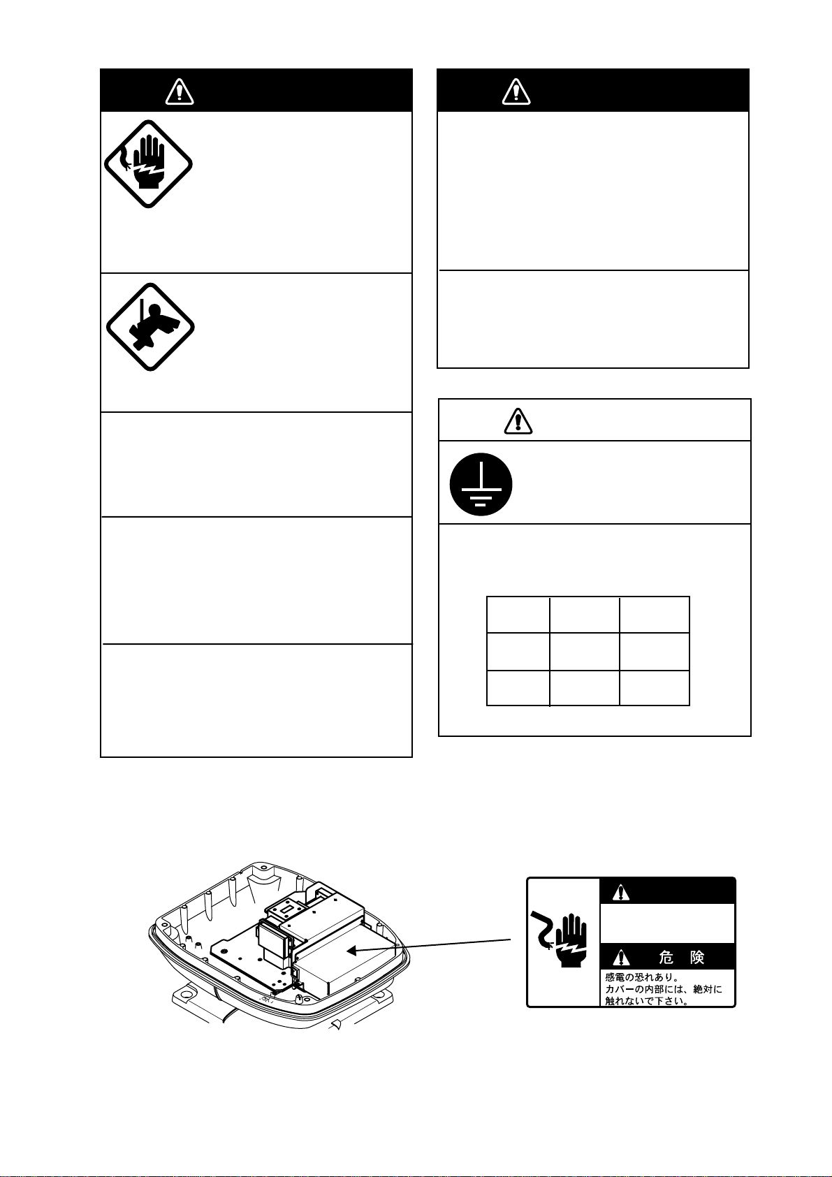
Observe the following compass safe
distances to prevent deviation of a
magnetic compass:
Standard Steering
compass compas
Display
unit
Scanner
unit
0.75 m 0.60 m
1.00 m 0.80 m
HIGH TENSION WARNING
DANGER
Electrical shock hazard.
Do not touch parts in side this cover.
Name: Danger Label
Type: 14-055-4202-0
Code No.: 100-245-220
ii
Page 5

TABLE OF CONTENTS
SYSTEM CONFIGURATION .............................................................iv
EQUIPMENTS LIST............................................................................v
1. MOUNTING
1.1 Mounting Methods for Scanner Unit..................................................................1-1
1.2 Fixing Holes in Mounting Platform ....................................................................1-1
1.3 Fastning the Radiator to the Radiator Bracket..................................................1-2
1.4 Mounting the Scanner Unit................................................................................1-2
1.5 Display Unit Mounting .......................................................................................1-4
2. CONNECTIONS
2.1 Connecting the Signal Cable.............................................................................2-1
2.2 Display Unit Connections..................................................................................2-2
2.3 Connection of External Equipment....................................................................2-3
2.4 Exchange of Fuse for 24/32V Power Supply.....................................................2-4
2.5 Checking the Installation...................................................................................2-4
3. ADJUSTMENTS
3.1 Preparation........................................................................................................3-1
3.2 Adjusting Tuning/V ideo......................................................................................3-1
3.3 Entering Antenna Height ...................................................................................3-1
3.4 Aligning Heading ...............................................................................................3-2
3.5 Adjusting Sweep T iming ....................................................................................3-2
3.6 Adjusting MBS...................................................................................................3-3
3.7 Selecting STC Curve.........................................................................................3-3
3.8 Setting Dead Sector ..........................................................................................3-3
3.9 Checking Magnetron Heater Voltage ................................................................3-4
4. INSTALLATION OF ARP-10 (OPTION)
4.1 Necessary Parts................................................................................................4-1
4.2 Mounting ...........................................................................................................4-1
4.3 Adjustments.......................................................................................................4-1
INSTALLATION MATERIALS, ACCESORIES, SPARE PARTS..... A-1
OUTLINE DRAWING ...................................................................... D-1
SCHEMATIC DIAGRAM ................................................................. S-1
iii
Page 6
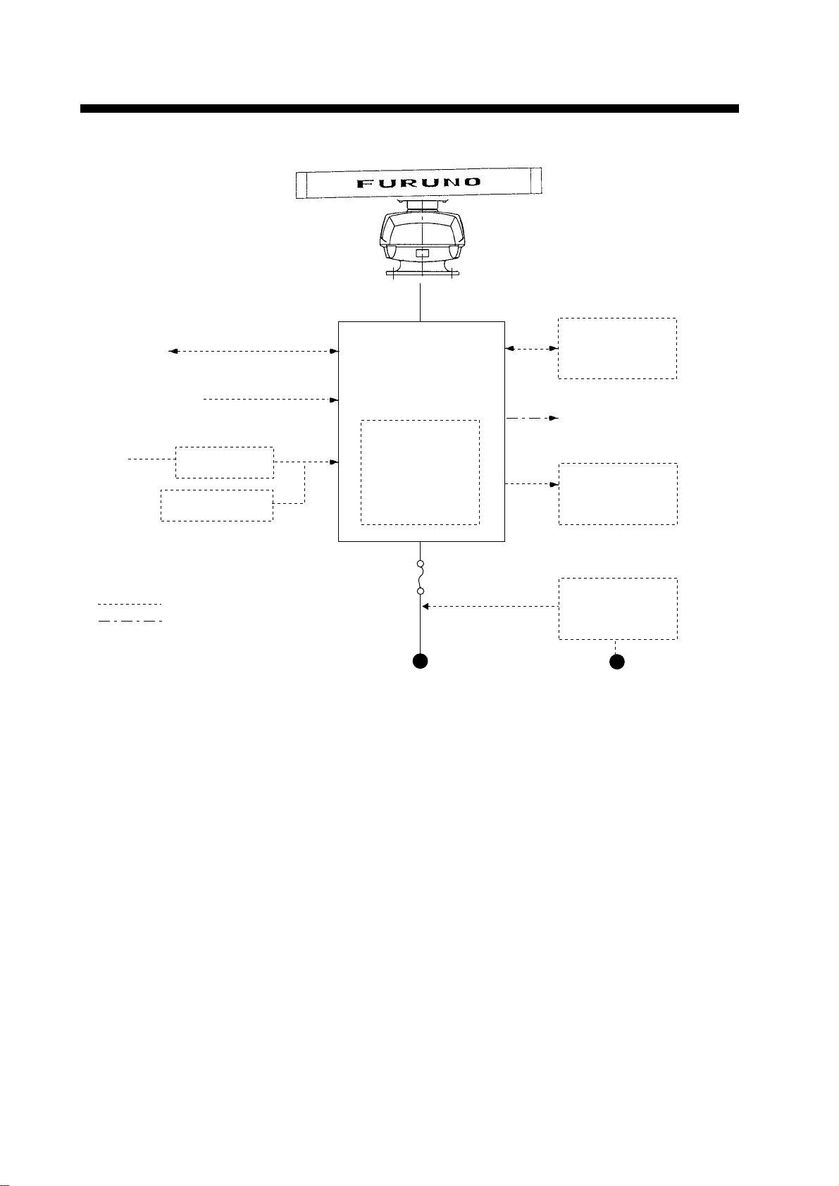
SYSTEM CONFIGURATION
Scanner Unit
MODEL 1932 MARK-2
XN10A-RSB-0070-064 (24 rpm)
XN10A-RSB-0073-064 (48 rpm)
MODEL 1942 MARK-2
XN12A-RSB-0070-059 (24 rpm)
XN12A-RSB-0073-059 (48 rpm)
Navigation
device
Video Sounder
IEC 61162* (In/Out)
IEC 61162* (In/Out)
Display Unit
RDP-118
Radar Plotter
RP-110
Remote Display
FMD-811/1800
Gyrocompass
*Equivalent to NMEA 0183
Gyro Converter
AD-100
Integrated Heading
Sensor PG-1000
: Option
: Local Supply
Auto Plotter
ARP-10
(24 rpm only)
12 VDC: 10A
24/32 VDC: 5A
12/24/32 VDC
External Alarm
Buzzer OP03-21
Rectifier
RU-3423
115/230 VAC
Note: Even though the display unit meets waterproof standard IPX-5, the connection of external buzzer, radar plotter and/or remote display can af fect waterproofness. W atertight integrity cannot be guaranteed. When these modification has been done, the display unit should
not be mounted where exposed.
Input data
Own ship’s position: GGA>RMC>RMA>GLL (GLL is available Ver.1.5 only)
Speed: RMC>RMA>VTG>VHW
Heading (True): HDT>HDG *1>HDM *1 >VHW>VHW
Heading (Magnetic): HDM>HDG *1>HDT *1>VHW>VHW
Course (True): RMC>RMA>VTG
Course (Magnetic): VTG>RMC>RMA
Waypoint (Range, Bearing): RMB>BWC>BWR
Loran time difference: RMA>GLC>GTD
Water depth: DPT>DBT>DBK>DBS
Water temperature: MTW>MDA
Time: ZDA
XTE: RMB>XTE>APB
*1
*1
*1: calculate by magnetic drift.
Output data
NMEA0183 (Ver.1.5/2.0), RS-422
TLL(target data) and RSD
iv
Page 7

Standard Supply
emaNepyT.oNedoCytQskrameR
EQUIPMENT LISTS
tinUrennacS
tinUyalpsiD811-PDR—1
noitallatsnI
slairetaM
seirosseccA00460-30PF278-680-000tes101840-30PF,01460-30PF
straPerapS00221-30PS569-680-000tes1
Optional Supply
emaNepyT.oNedoCskrameR
460-0700-BSR-A01NX—
460-3700-BSR-A01NX— mpr84,2M2391roF
950-0700-BSR-A21NX—
950-3700-BSR-A21NX— mpr84,2M2491roF
00391-30PC419-680-000
01391-30PC519-680-000
02391-30PC619-680-000
03391-30PC719-680-000
tceleS
eno
tceleS
eno
tceleS
eno
mpr42,2M2391roF
mpr42,2M2491roF
,elbacrewop,10481-30PC
elbaclangism01
,elbacrewop,10481-30PC
elbaclangism51
,elbacrewop,10481-30PC
elbaclangism02
,elbacrewop,10481-30PC
elbaclangism03
*rezzuBlanretxE12-30PO790-030-000
reifitceR3243-UR344-030-000
001-7000FPS6A-JM732-521-000
050-2100FPS6A-JM424-431-000
ssorc
.yssAelbaC
001-2100FPS6A-JM718-331-000
ssorc
001-9000FPS6A-JM632-521-000
elbaClangiS050-3000FPS6A-JM306-711-000dneenotarotcennocP6/w,m5
tiKtnuoMhsulF541-30PO060-674-800tinuyalpsidroF
rettolPotuA01-PRA258-680-000.rennacsmpr42htiwelbaliavA
*rettolPradaR011-PR-
.yssAelbaC500-6000FPL42B-JM834-041-000rotcennocretrevnocelbaC
.desopxeerehwdetnuom
P6/wm01,rosnesgnidaehroF
thgiarts,sdnehtobtarotcennoc
m5,rednuosoediv,diavanroF
,sdnehtobtarotcennocP6/w
m01,rednuosoediv,diavanroF
,sdnehtobtarotcennocP6/w
,rednuosoediv,diavanroF
P6/wm01,rosnesgnidaeh
edisenotarotcennoc
lanretxefonoitcennoceht,5-XPIdradnatsfoorpretawsteemtinuyalpsidehthguohtnevE:*
ytirgetnithgitretaW.ssenfoorpretawtceffanacyalpsidetomerro/dnarettolpradar,rezzub
ebtondluohstinuyalpsideht,enodneebsahnoitacifidomesehtnehW.deetnaraugebtonnac
v
Page 8
1. MOUNTING
1.1 Mounting Methods for Scanner Unit
• The scanner unit is generally installed either on top of the wheelhouse or on the
radar mast on a suitable platform. Locate
the scanner unit where there is a good allround view. Any obstruction will cause
shadow and blind sectors. A mast for instance, with a diameter considerably less
than the width of the radiator, will cause
only a small blind sector, but a horizontal
spreader or crosstrees in the same horizontal plane as the scanner unit would be
a much more serious obstruction; you
would need to place the scanner unit well
above or below it.
• It is rarely possible to place the scanner
unit where a completely clear view in all
directions is available. Thus, you should
determine the angular width and relative
bearing of any shadow sectors for their influence on the radar at the first opportunity after fitting.
• Do not paint the radiator aperture, to ensure proper emission of the radar waves.
• When this radar is to be installed on larger
vessels, consider the following points:
• The signal cable run between the scanner and the display comes in lengths
of 10 m (standard), 15 m, 20 m and 30
m. Whatever length is used it must be
unbroken; namely , no splicing allowed.
• Deposits and fumes from a funnel or
other exhaust vent can adversely affect
the aerial performance and hot gases
may distort the radiator portion. The
scanner unit must not be mounted
where the temperature is more than
70 C.
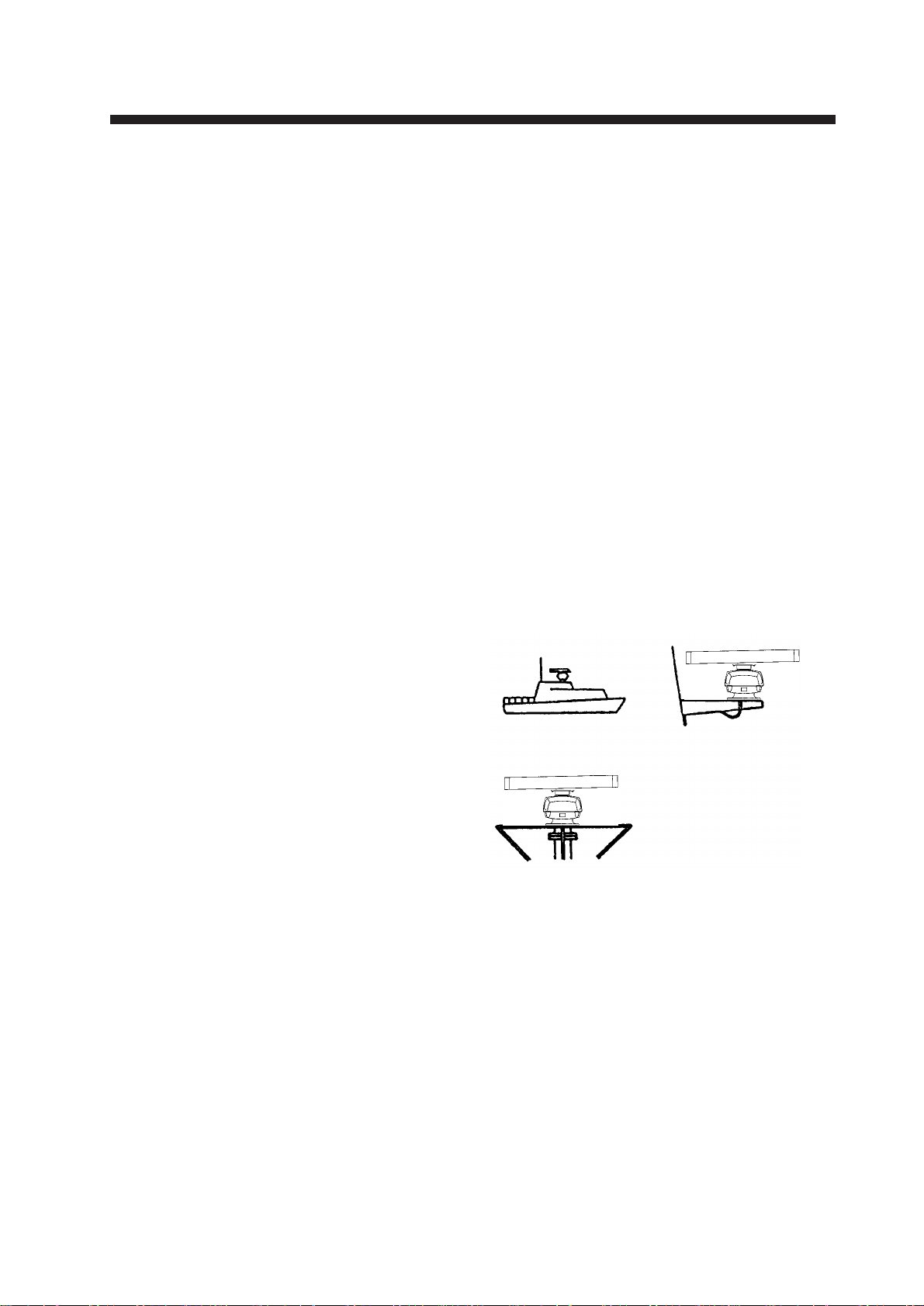
As shown in the figure below, the scanner
unit may be installed on the bridge, on a common mast or on the radar mast.
• If you have a radio direction finder on your
boat, locate its antenna clear of the scanner unit to prevent interference to the direction finder. A separation of more than
two meters is recommended.
• To lessen the chance of picking up electrical interference, avoid where possible
routing the signal cable near other onboard
electrical equipment. Also avoid running
the cable in parallel with power cables.
• A magnetic compass will be affected if
placed too close to the scanner unit. Observe the following compass safe distances to prevent deviation of a magnetic
compass: Standard compass, 1.00 m,
Steering compass, 0.75 m.
(a) On bridgh
(c) Radar mast
Figure 1-1 Scanner unit mounting methods
(b) Common mast
1.2 Fixing Holes in Mounting Platform
Referring to the outline drawing on page D1, drill five holes in the mounting platform:
four holes of 15 mm diameter for fixing the
scanner unit and one hole of 25-30 mm diameter for the signal cable.
1-1
Page 9
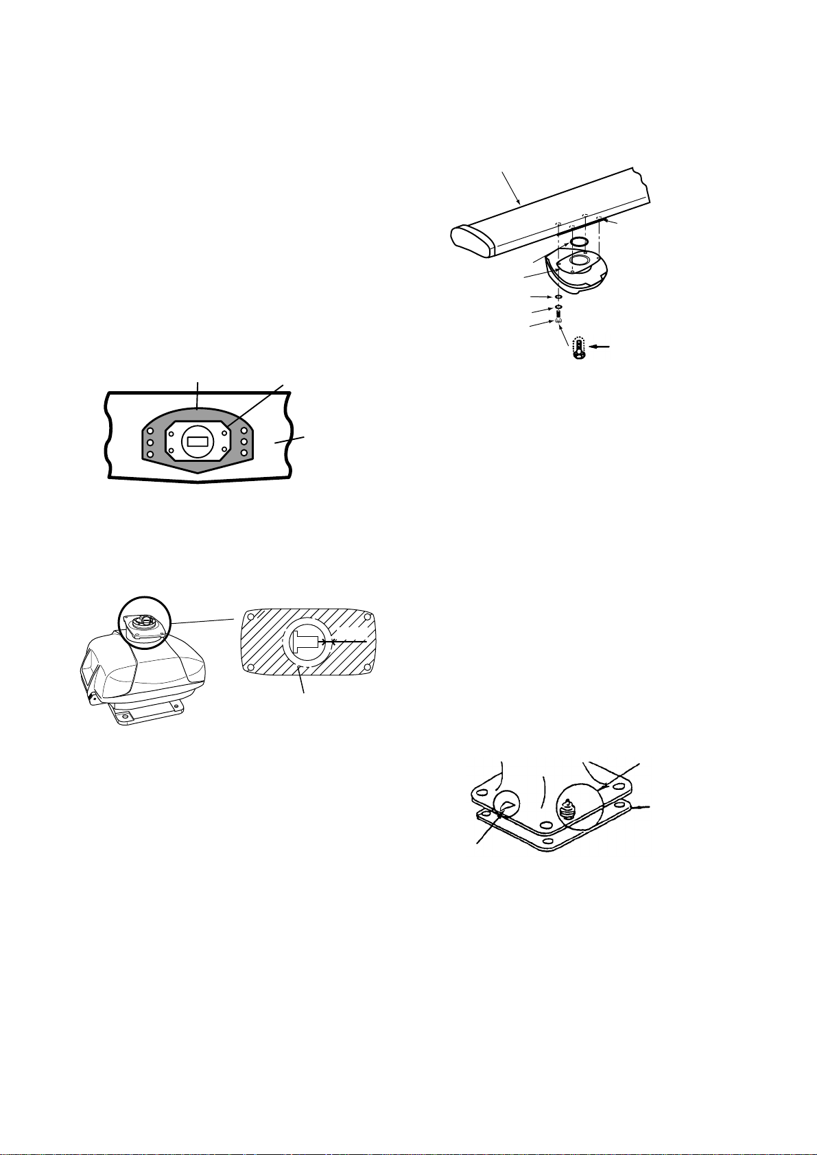
1.3 Fastening the Radiator to
the Radiator Bracket
For your reference, scanner installation materials list appears in the packing lists at the
back of this manual.
1. Remove the radiator cap from the radiator bracket.
2. Coat contacting surface between scanner radiator and radiator bracket with anticorrosive sealant as shown in Figure 1-2
(scanner unit XN10A) or Figure 1-3 (scanner unit XN12A).
Coat hatched area with
anticorrosive sealant.
Groove
Radiator
anticorrosive sealant. Fasten the scanner
radiator to the radiator bracket with the
radiator fixing bolts, flat washers and
spring washers.
Scanner
radiator
Coat threaded
holes with anti-
O-ring
Radiator bracket
Flat washer
Spring washer
Hex head bolt
(M8 x 30)
corrosive
sealant.
Coat bolts with
anticorrosive
sealant.
Figure 1-4 Fastening the radiator bracket to
the scanner unit chassis (shown: XN12A)
Figure 1-2 Coating the bottom of
scanner radiator for XN10A with
anticorrosive sealant
RADIATOR BRACKET
(top view)
10mm
Coat hatched area with
anticorrosive sealant.
Figure 1-3 Coating scanner bracket
for XN12A with anticorrosive sealant
3. Coat threaded holes on the scanner radiator with anticorrosive sealant.
4. Grease the O-ring and set it to the radiator bracket.
5. Lay the scanner radiator on the radiator
bracket.
1.4 Mounting the Scanner Unit
The scanner unit can be mounted using the
fixing holes on the outside (240 x 240 nm) or
inside (140 x 150 nm) the scanner unit.
Outside fixing holes
Use the hex head bolt ( supplied ) to mount
the scanner unit as below.
1 . Lay the corrosion-proof rubber mat ( sup-
plied) on the mounting platform.
Ground
terminal
Rubber
mat
Bow mark
Figure 1-5 Location of rubber mat
6. Coat the radiator fixing bolts (4 pcs.) with
1-2
Page 10
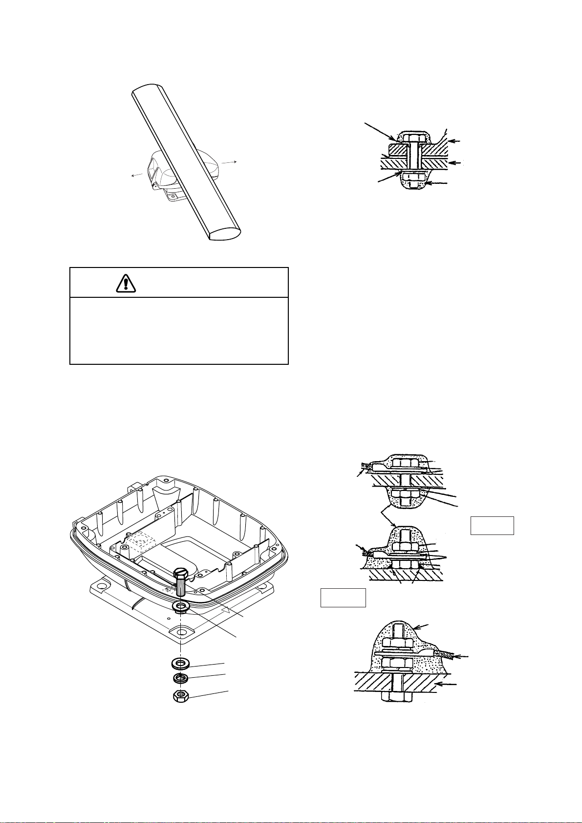
2. Lay the scanner unit on the mounting platform, orienting it as shown in Figure 1-6.
BOW
STERN
4. Pass flat washers, spring washers and
nuts onto hex bolts. Fasten by tightening
nuts. Do not fasten by tightening the hex
bolts; seal washers may be damaged.
Seal washer
Scanner
Rubber mat
Flat washer
unit
Mounting
platform
Silicone
sealant
Figure 1-8 How to fasten scanner unit to
mounting platform
Figure 1-6 Scanner unit (Shown: XN12A)
CAUTION
Do not lift the scanner unit by the
radiator; lift it by the housing.
The radiator may be damaged.
3. Insert four hex bolts and seal washers
from the top of the scanner housing. Insert the seal washers with the larger diameter next to the bolt heads. Be sure
the seal washer , not other washers, is next
to bolt head.
5. Coat flat washers, spring washers, nuts
and exposed parts of bolts with anticorrosive sealant.
6. Prepare ground point in mounting platform
(within 300 mm of ground terminal on
scanner unit) using M6 x 25 bolt, nut and
flat washer.
7. Run the ground wire (RW-4747, 370 mm)
between the ground terminal and ground
point.
8. Coat ground terminal and ground point
with silicone sealant as shown in Figure
1-9.
Hex bolt
Flat washer
Ground
terminal
Ground
wire
Silicone
sealant
OR
Flat washer
Spring washer
Hex nut
GROUND
POINT
Hex nut
Spring washer
Flat washer
Hex nut
Hex bolt
Seal washer
Flat washer
Spring washer
Nut
Figure 1-7 Fixing the scanner unit chassis
GROUND
TERMINAL
Weld here.
Silicone
sealant
Ground
wire
Scanner
unit
Figure 1-9 How to coat ground point and
ground terminal with silicone sealant
1-3
Page 11

Fixing holes inside szcanner unit
1.5 Display Unit Mounting
This method requires removal of the RF unit
in the scanner unit to access inside fixing
holes. Use hex head bolts, flat washers,
spring washers and nuts (local supply) to
mount the scanner unit, confirming lengh of
bolts.
1. Loose four scanner bolts to open the scanner unit. Refer to Figure 11 for location.
Hex head bolt
M8X25
SUS 2pcs.
Hex head bolt
M10X20
SUS 4pcs.
Spring Washer
M10 SUS
4 pcs.
Upper chassis
RFunit
Cover
Square bushing
Lower chassis
Pan head screw
M3X8 4pcs.
Figure 10 Scanner unit chassis, upper
chassis separated
2. Unplug connector connected between upper and lower chassis.
3. Separate upper chassis from lower chassis by removing two hex head bolts.
4. Remove cover by unfastening four pan
head screws.
5. Remove connector from RF unit .
6. Remove RF unit by unfastening four hex
head bolts.
7. Lay the corrosion-proof rubber mat (supplied) on the mounting platform.
8. Fasten the lower chassis to the mounting
platform with hex head bolts, spring
washers, flat washers and nuts (local supply ), and then coat flat washers, nuts and
exposed parts of bolts with anticorrosive
sealant. Cut a slit in rubber bushing and
insert bolt into bushing. Do not use seal
washers.
9. Reassemble RF unit, cover and upper
chassis.
10. Set four knob caps (supplied) into
outside fixing holes.
11. Do steps 6-8 in “Outside fixing holes”.
1-4
Mounting considerations
When selecting a mounting location for the
display unit keep in mind the following points:
• Provide adequate space behind and
around the unit to permit circulation of air
and to provide convenient access to the
rear connection.
• Even though the picture is quite legible
even in bright sunlight, keep the display
unit out of direct sunlight or at least shaded
because of heat that can build up inside
the cabinet.
• Locate the display unit in a position where
you can view and operate it conveniently
but where there is no danger of salt or
fresh water spray or immersion.
• The orientation of the display unit should
be so the radar screen is viewed while the
operator is facing in the direction of the
bow. This makes determination of your
position much easier.
• Make sure you allow enough clearance
both to get to the connectors behind the
unit and to allow you to get your hands in
on both sides to loosen or tighten the
mounting knobs. Make sure you leave at
least a foot or so of “service loop” of cables
behind the unit so it can be pulled forward
for servicing or easy removal of the connectors.
• The compass safe distance of 0.75 meters
(standard compass) and 0.6 meters (steering compass) should be observed to prevent deviation of the magnetic compass.
• Even though the display unit meets waterproof standard IPX-5, the connection of
external buzzer, radar plotter and/or remote display can affect waterproofness.
W atertight integrity cannot be guaranteed.
When these modification has been done,
the display unit should not be mounted
where exposed.
Mounting
The display unit is designed to be mounted
on a tabletop or bulkhead.
1. Using the hanger as a template, mark
screw locations in the mounting location.
2. Fix the hanger to the mounting location
with five M6 tapping screws (supplied).
3. Fit the knob bolts to the display unit. In-
stall the display unit in the hanger. Tighten
the knob bolts securely.
Page 12

2. CONNECTIONS
2.1 Connecting the Signal Cable
Only the signal cable runs from the display
unit to the scanner unit. In order to minimize
the chance of picking up electrical interference, avoid where possible routing the signal cable near other onboard electrical
equipment. Also, avoid running the cable in
parallel with power cables. Pass the cable
through the hole and apply sealing compound
around the hole for waterproofing.
1. Open the scanner cover by loosening two
screws, and then fix the stay.
Stay
Cable gland
3. Unfasten the cable gland assembly (plate,
gasket, flat washer).
4. Pass the signal cable w/connector
through the bottom of the scanner unit
chassis. Pass the cable through the gland
assembly as shown below.
Figure 2-3 Passing the signal cable through
the cable gland assembly
5. Fasten the crimp-on lug on the shield to
one of the fixing bolts of the cable gland
assembly.
6. Position the signal cable so that no more
than 4 cm of the sheath is exposed as
shown in the figure below. Tighten fixing
bolts on the cable gland assembly .
Fixing screw
Figure 2-1 Scanner unit chassis,
cover opened
2. Fabricate the signal cable as shown below.
Figure 2-2 Fabrication of signal cable
Figure 2-4 How to fix signal
cable in cable gland
2-1
Page 13

7. Unfasten four screws shown in the figure
below.
Four screws
9. Connect the signal cable to the RTB
Board (03P9249), referring to the interconnection diagram and the figure below.
Note that connector VH2P is not used.
10.Attach three EMI cores to the signal cable
as shown below.
J821 VH9P
Figure 2-5 Scanner unit chassis,
cover opened
8. Pass the signal cable through the cable
protector.
Cable
protector
Figure 2-6 Scanner unit chassis,
cover opened
Lead in
cable here.
EMI core
RFC-13
Route cable along here.
J824 NH13P
J823 VH4P
Clamp
Figure 2-7 Scanner unit chassis,
cover opened
1 1.Fix the signal cable with the cable clamp.
12.Release the stay and close the cover.
Loosely fasten the cover fixing screws;
you will have to make some adjustments
inside after completion of wiring.
2.2 Display Unit Connections
Power cable connector
Signal cable connector
(DJ-1, waterproof)
Left: HDG connector
Middle: NMEA connector (for NAV)
Right: NMEA connector (for E/S)
Figure 2-8 Connection on the display unit
External equipment
connector
(For Remote Display,
External Alarm Buzzer
OP03-21 and Radar
Plotter, RP-110)
Ground terminal
CAUTION
Ground the equipment to prevent
mutual interference.
2-2
Page 14

Connection procedure
epyT.onedoCskrameR
001-7000FPS6A-JM732-521-000)m01(P6-P6
001-9000FPS6A-JM632-521-000)m01(rotcennoc/w
050-3000FPS6A-JM306-711-000)m5(rotcennoc/w
Heading sensor connection
1. Connect the power cable to the power
cable connector on the rear of the display
unit.
2. Connect the signal cable to connector DJ1 on the rear of the display unit.
3. Run a ground wire (local supply) between
the ground terminal on the rear of the display unit and the ship’s superstructure.
2.3 Connection of External
Equipment
Navigation aid, video sounder
connection
If your navigation aid can output data in IEC
61162 (NMEA 0183) format, your vessel’s
position in latitude and longitude, the range
and bearing to waypoint, speed and course
may be input to this radar, and be seen on
the screen.
Further if your video sounder can output
depth data in IEC61 162 (NMEA 0183) format,
depth can be displayed on the radar screen.
You will need an NMEA cable. The following
cables are optionally available.
epyT.onedoCskrameR
050-2100FPS6A-JM424-431-000)m5(P6-P6
001-2100FPS6A-JM718-331-000)m01(P6-P6
050-3000FPS6A-JM306-711-000)m5(rotcennoc/w
001-9000FPS6A-JM632-521-000)m01(rotcennoc/w
Heading signal can be connected to the
“HDG” connector. You will need a heading
sensor cable. The following cables are optionally available.
Input/Output Data List
ledoM
2M165VCF1J)5.1(3814tuO/nI
L185VCFAEMN)0.2/5.1(3816tuO/nI
L285VCFAEMN)0.2/5.1(3816tuO/nI
192VCFAEMN)0.2/5.1(3816tuO/nI
292VCFAEMN)0.2/5.1(3816tuO/nI
866VCFAEMN)5.1(3814tuO/nI
L006VCFAEMN)0.2/5.1(3816tuO/nI
0181PGTUO/NI)0.2/5.1(3816tuO/nI
2M0013PGTUO/NI)5.1(3816tuO/nI
2M0008PGAEMN)0.2/5.1(3814tuO/nI
2M0008SPAEMN)0.2/5.1(3814tuO/nI
08PG1ATAD)0.2/5.1(3816tuO/nI
08PG2ATAD)0.2/5.1(3816tuO/nI
C0161PGAEMN)0.2/5.1(3816tuO/nI
FC0161PGAEMN)0.2/5.1(3816tuO/nI
rotcennoC
emaN
ataDniPtuO/nI
Note: All plotters listed in the table above can
receive TLL data (radar target position).
This radar can output NA V data received from
a navaid to an echosounder.
J1352 (NMEA)
(TLL)
SPU9211
1932 MARK2/42 MARK2
INT9213
J1354
Figure 2-9 Data flow
Navaid
Echosounder
2-3
Page 15

2.4 Exchange of Fuse for 24/32V Power Supply
The power cable comes with a 10A fuse in
its the fuse its holder . This fuse is for use with
a 12V DC power supply. For 24V/32V DC
power supply, replace the fuse with the 5A
fuse (supplied) and attach 5A label (supplied)
to fuse holder .
CAUTION
Use the proper fuse.
Use of an improper fuse can damage the
equipment and void the warranty.
2.5 Checking the Installation
After completing the installation, it is a good
idea to recheck it to be sure all steps were
correctly done. Use the table below to check
the installation.
❑ The signal cable is securely retained
against the mast or mounting platform and
is free of interference from running rigging.
❑ The cable gland or entry on the deck, if
provided, is waterproofed.
❑ The power connections to the battery are
of correct polarity.
❑ The plugs at the rear of the display unit
are tightly fastened.
❑ The fuse in the power cable is 10A (12V)
or 5A (24V/32V DC).
2-4
Page 16

3. ADJUSTMENT
This section covers adjustment of the radar
after installation. You will need to
• adjust tune/video amplifier level
• enter antenna height
• align heading
• adjust sweep timing
• adjust main bang suppression
• select STC curve
• set a dead sector, and
• confirm magnetron heater voltage.
These adjustments are done through the in-
stallation setup menu.
3.1 Preparation
Most adjustments and initial settings may be
completed on the Installation Setup menu,
and you can display this menu as follows:
1. Turn off the radar. While pressing and
holding down the [GAIN] control (at least
three seconds), press the [POWER] key .
3.2 Adjusting Tuning/Video
Do the following to automatically adjust tuning and video amplifier level input.
1. Press the [STBY/TX] key to transmit.
WARNING
Before transmitting the radar make sure
no one is near the scanner unit, to prevent the potential risk of being struck
by the rotating scanner and exposure
to RF radiation hazard.
2. On the Installation Setup menu, select “8.
Tune/Video Adjustment” and press the
[ACQ/ENTER] key.
3. The unit automatically adjusts tuning and
video, displaying the following message.
[ Tune/Video Auto Adjustment ]
Now under correction.
Return to installation setup
menu after the correction.
2. Press the [MENU] key , select “OTHERS”
by using the omnipad, and press [ACQ/
ENTER] key.
3. Select “24. Installation Setup”.
4. Press the [ACQ/ENTER] key to open the
Installation Setup menu.
[ Installation Setup ]
Select item by omnipad
and press ENTER key.
1 . Nav Talker
2 . Depth Unit
3 . Temp Unit
4 . Hdg Sensor
5 . Key Beep
6 . Ant on Tx
7 . Dead Sector
8 . Tuning/Video Auto Adjustment
9 . Heading Alignment
10. Sweep Timing Adjustment
11. MBS Adjustment
12. Ant Height
13. STC Curve
14. Ope Mode
15. Hours in Use
16. Tx Hours
All
m
ßC
Magnet
Off
Rotate
180ß~180ß
Low
Sharp
Master
000001.5H
000000.0H
GPS
fa
ßF
Gyro
On
Stop
Mid
Std
Slave
LC
ft
High
Gntl
Figure 3-2 Tune/video auto
adjustment message
4. When adjustment is completed, the message disappears.
3.3 Entering Antenna Height
The STC curve changes with respect to antenna height above the waterline. Enter antenna height above the waterline to optimize
the STC curve.
1. Select “12. Ant Height” from the Installation Setup menu and press the [ACQ/ENTER] key.
2. Operate the omnipad to select antenna
height above the waterline; Low (3 m or
less), Mid (3 to 6 m) or High (6 to 10 m).
3. Press the [ACQ/ENTER] key.
Figure 3-1 Installation Setup menu
3-1
Page 17

3.4 Aligning Heading
3.5 Adjusting Sweep Timing
(Adjustment sector: 0~359.90)
You have mounted the scanner unit facing
straight ahead in the direction of the bow.
Therefore, a small but conspicuous target
dead ahead visually should appear on the
heading marker (zero degrees).
In practice, you will probably observe some
small bearing error on the display because
of the difficulty in achieving accurate initial
positioning of the scanner unit. The following
adjustment will compensate for this error.
1. Identify a suitable target (for example, ship
or buoy) at a range between 0.125 to 0.25
nautical miles, preferably near the heading marker. To lessen error, keep echoes
in the outer half of the picture by changing the range. Also, be sure the zoom and
off center functions are off.
2. Select “9. Heading Alignment” from the
Installation Setup menu and press the
[ACQ/ENTER] key. The following message appears:
[Heading Alignment]
Set EBL1 to center of target
dead ahead and press ENTER.
(Adjustment range: 0.000~4.266 nm)
This adjustment ensures proper radar performance, especially on short ranges. The
radar measures the time required for a transmitted echo to travel to the target and return
to the source. The received echo appears on
the display based on this time. Thus, at the
instant the transmitter is fired, the sweep
should start from the center of the display
(sometimes called sweep origin).
A trigger pulse generated in the display unit
goes to the scanner unit through the signal
cable to trigger the transmitter (magnetron).
The time taken by the signal to travel up to
the scanner unit varies, depending largely on
the length of the signal cable. During this period the display unit should wait before starting the sweep. When the display unit is not
adjusted correctly , the echoes from a straight
local object (for example, a harbor wall or
straight pier) will not appear with straight
edges – they will be seen as “pushed out” or
“pulled in” near the picture center. The range
of objects will also be incorrectly shown.
Correction 0.0°
<Press MENU for inst setup>
Figure 3-3 Heading alignment message
3. Operate the omnipad to bisect target selected at step 1 with the heading marker.
4. Press the [ACQ/ENTER] key.
5. As a final test, move the boat towards a
small buoy and confirm that the buoy
shows up dead ahead on the radar when
it is visually dead ahead.
(1) Correct
(2) Target pushed
inward
(3) Target pushed
outward
Figure 3-4 Examples of improper and
correct sweep timing
1. Transmit on the shortest range and confirm that the [GAIN] and [A/C SEA] controls are properly adjusted.
2. Visually select a target which forms a
straight line (for example, harbor wall,
straight pier).
3. Select “10. Sweep Timing Adjustment”
from the Installation Setup menu and
press the [ACQ/ENTER] key . The following message appears:
3-2
Page 18

[ Sweep Timing Adjustment ]
Use omnipad to straighten
target and press ENTER key.
1. Select “13. STC Curve” from the Installation Setup menu and press the [ACQ/ENTER] key.
Correction 0.000 nm
<Press MENU for inst setup>
Figure 3-5 Sweep timing adjustment
message
4. Operate the trackball to straighten the target selected at step 2, and then press the
[ACQ/ENTER] key.
3.6 Adjusting MBS
(Adjustment range: 0.00~0.25)
Main bang, a large filled circle which appears
at the display center on short ranges, can be
suppressed as follows:
1. Transmit on long range about 10 minutes.
2. Adjust the gain to show a small amount
of noise on the display.
2. Select STC curve desired;
Sharp: The effective range of the [A/C
SEA] control is relatively short.
Std: Between Sharp and Gentle.
Gntl (Gentle): The effective range of
the [A/C SEA] control is relatively long.
3. Press the [ACQ/ENTER] key.
3.8 Setting a Dead Sector
When the scanner is installed at a close distance in front of the wheelhouse, the radar
should be set not to transmit within that area,
to prevent microwave hazard. The dead sector area graphic can be turned on/off on the
OTHERS menu.
1. Select “7. Dead Sector” from the Installa-
tion Setup menu and press the [ACQ/ENTER] key.
3. Change to the 0.125 nautical mile range
and adjust the [A/C SEA] control.
4. Select “1 1. MBS Adjustment” from the Installation Setup menu and press the
[ACQ/ENTER] key. The following message appears:
[MBS Adjustment]
Set value by T-ball
and press ENTER key.
Correction 000
<Press MENU for inst setup>
Figure 3-6 MBS adjustment message
5. Operate the trackball to suppress main
bang (adjustment range: 000 to 025).
6. Press the [ACQ/ENTER] key.
3.7 Selecting STC Curve
The STC curve changes with respect to the
antenna height above the waterline. The default STC curve can be maintained in most
cases. If necessary the STC curve can be
changed as follows:
2. Operate the omnipad to enter starting
point of sector (in figures).
3. Press the [ACQ/ENTER] key.
4. Operate the omnipad to enter ending point
of sector (in figures, Max: 270°).
5. Press the [ACQ/ENTER] key.
Note: This setting should be done after other
adjustment are finished.
Dead
sector
Figure 3-7 Dead sector
3-3
Page 19

3.9 Checking Magnetron Heater
Unf
5. Confirm that the meter reads 7.5 V ±0.1 V .
Voltage
Magnetron heater voltage is formed on the
MD Board of the scanner unit, and is
preadjusted at the factory for use with any
length of signal cable. Therefore no adjustment is required. However , check magnetron
heater voltage as follows:
1. Turn on the radar and leave it in
by.
2. Open the scanner cover.
3. Unfasten two screws to remove the RF
section cover.
stand-
DANGER
ELECTRICAL SHOCK HAZARD
This check is done with the
power on — DO NOT touch
the magnetron.
6. Close the scanner cover and tighten the
cover fixing screws.
Magnetron
asten two
screws.
Figure 3-8 Scanner unit, cover opened
4. Connect a multimeter, set to 10 VDC
range, between test point J825#4 and
J825#6(GND) on the RTB Board
(03P9249).
Measure voltage
at this connector
(J825).
Figure 3-9 Scanner unit, cover removed
3-4
Page 20

4. INSTALLATION OF ARP-10 (OPTION)
NOTICE
This option is not available
with 48 rpm scanner unit.
4.1 Necessary Parts
emaNepyT.oNedoCytQ
draoB01-PRA7009P81039-674-8001
recapS02-QS056-108-0004
rehsaWgnirpSW1915C3M402-468-0004
wercSdaeHnaPW0072C8x3M404-188-0006
wercSdaeHnaP
*rehsaw/w
8x3M
01MRWS
477-508-0003
(3)Faster the ARP-10 Board to the chas-
sis with three pan head screws and
springs washers.
Front
Spring Washer
Spacer
SQ-20 3 pcs.
Pan Head
Screw
M3 x 8 3 pcs.
ARP-10 Board
18P9007
M3 3 pcs.
P107
J107
SPU Board
SPU9211
$
$
Note: Remaining hardware may be discarded.
*Not used.
4.2 Mounting
1. Turn off the power. Remove the cover
from the display unit as follows:
1 Unfasten four binding screws (M4 x 10).
2 Unfasten six binding screws (M3 x 10).
3 Remove three rubber covers to unfas-
ten three hex nuts.
4 Loosen two hex nuts.
1
2
4
1
3
Figure 4-1 Display unit, rear view
2. Fasten the ARP-10 Board to the righthand chassis of the display unit, using the
pan head spacers, screws, and washers
(supplied) as follows.
(1)Attach three spacers.
(2) Attach the P107 connector from the
ARP-10 Board to J107 connector on
the SPU Board.
1
2
1
Figure 4-2 How to mount the
ARP-10 Board
4.3 Adjustments
Input signal
1. Connect the gyrocompass. Turn on the
radar and transmit.
2. Press the [MENU] key and select the
OTHERS menu
3. Select “23. Self T est” and press the [ACQ/
ENTER] key . Confirm that the ARP-10 test
results show OK for SPEED, COURSE,
TRIGGER< BP and HP.
Video signal
Confirm the following on the ARP-10 test display:
• Video is “OK.”
• Adjust the GAIN, A/C and A/C RAIN controls so FE-DATA1 and FE-DATA2 indications on the ARP-10 TEST show less
than 1,000. Also, raise/lower the gain
while watching the FE-DATA1 and FEDATA2 indications. Confirm that the FEDATA1 and FE-DATA2 indications rise/
lower according to GAIN control adjustment.
4-1
Page 21

Page 22

Page 23

Page 24

Page 25

Page 26

Page 27

Page 28

Page 29

Page 30

Page 31

Page 32

Page 33

 Loading...