

Page 1

COLOR GPS/PLOTTER/SOUNDER
Back
COLOR DGPS/PLOTTER/SOUNDER
GP-1850WF
GP-1850WDF
PRINTED IN JAPAN
Page 2

Thepaperusedinthismanual
9-52 Ashihara-cho,9-52 Ashihara-cho,
A
A
*
0
*
0
*
0
*
0
*
I
*
I
*
I
*
I
Nishinomiya 662-8580, JAPANNishinomiya 662-8580, JAPAN
Telephone :Telephone : 0798-65-21110798-65-2111
FaxFax 0798-65-42000798-65-4200
::
iselementalchlorinefree.
FURUNO Authorized Distributor/DealerFURUNO Authorized Distributor/Dealer
ll rights reserved.
ll rights reserved.
Pub. No.Pub. No. IME-44252-A4IME-44252-A4
(( DAMIDAMI ))
GP-1850WF/1850WDFGP-1850WF/1850WDF
Printed in JapanPrinted in Japan
FIRST EDITION :FIRST EDITION :AUG.AUG. 20022002
A4A4 :: SEP.SEP. 09, 200509, 2005
0080937200*
0080937200*
0080937200*
0080937200*
* 0 0 0 8 0 9 3 7 2 0 0 ** 0 0 0 8 0 9 3 7 2 0 0 *
ME44252A40*
ME44252A40*
ME44252A40*
ME44252A40*
* I M E 4 4 2 5 2 A 4 0 ** I M E 4 4 2 5 2 A 4 0 *
Page 3
SAFETY INSTRUCTIONS
Safety Instructions for the Installer
WARNING
Do not work inside the
equipment unless totally
familiar with electrical
circuits.
Hazardous voltage which can
shock, burn or cause serious
injury exists inside the equipment.
Turn off the power at
the mains switchboard
before beginning the
installation.
Post a sign near the
switch to indicate it
should not be turned on
while the equipment is
being installed.
Fire, electrical shock or
serious injury can result if the
power is left on or is applied
while the equipment is being
CAUTION
Ground the equipment to
prevent electrical shock
and mutual interference.
Confirm that the power supply voltage
is compatible with the voltage rating
of the equipment.
Connection to the wrong power supply
can cause fire or equipment damage. The
voltage rating appears on the label at the
rear of the display unit.
Use the correct fuse.
Use of a wrong fuse can cause fire or
equipment damage.
Keep the following compass safe
distance.
Standard Steering
Display unit 0.5 m 0.3 m
CAUTION
When handling the transducer cable,
keep in mind the following points.
Keep the cable away from oil and
fuel.
Keep the cable away from the place
where it may be damaged during the
installation.
Do not paint the cable.
The sheath of the transducer cable is made
of chlonophrene rubber (or vinil chloride).
Therefore, do not paint the seath with
organic liquid (such as toluene) since it
may harm the seath.
i
Page 4

TABLE OF CONTENTS
SYSTEM CONFIGURATION................................................................................ iii
EQUIPMENT LISTS.............................................................................................iv
1. INSTALLATION .............................................................................................1-1
1.1 Installation of Display Unit............................................................................................ 1-1
1.2 Installation of Antenna Unit.......................................................................................... 1-3
1.3 Installation of Transducers........................................................................................... 1-4
1.4 Installation of Sensors............................................................................................... 1-20
2. WIRING.......................................................................................................... 2-1
3. INITIAL SETTINGS ....................................................................................... 3-1
3.1 NMEA Setting.............................................................................................................. 3-1
3.2 Output Data Sent ences ............................................................................................... 3-3
3.3 Antenna Height............................................................................................................ 3-4
3.4 DGPS Setting.............................................................................................................. 3-5
3.5 External Equipment Setup (Option).............................................................................3-7
3.6 Selecting the Echo Sounder Output Power.................................................................. 3-9
4. INCORPORATION OF DGPS BEACON RECEIVER KIT
(for GP-1850WF)...........................................................................................4-1
PACKING LISTS............................................................................................... A-1
OUTLINE DRAWINGS...................................................................................... D-1
INTERCONNECTION DIAGRAM ......................................................................S-1
ii
Page 5
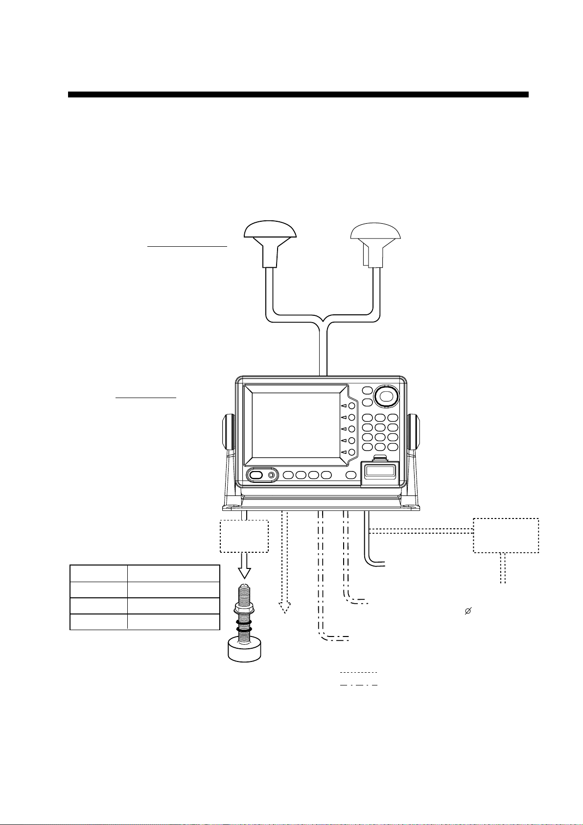
Ship's mains
12-24 VDC
External equipment
(Autopilot, etc.)
DGPS beacon receiver
GP-1850WF only
Transducer
Temp. sensor
(option)
Antenna unit
Receives signal from
GPS satellite and beacon
reference station
(GP-1850WDF only).
Display unit
Ship's position is
calculated in longitude
and latitude from signal
received from the antenna unit and displayed
on the screen.
GPA-017
(for GP-1850WF)
*Matching
Box
MB-1000
*Required for 1 kW transducer only
GPA-019
(for GP-1850WDF)
Category of Units
Unit Category
Display unit
Antenna unit
Exposed to weather
Exposed to weather
Transducer Submerged in water
: Option
: Local Supply
Rectifier
RP-62
Ship's mains
100/110/115/220/230 VAC
1 , 50/60 Hz
SYSTEM CONFIGURATION
The GP- 1850WF/1850 WDF mai nly consi sts of a display unit, a GPS antenna and a dual
frequency transducer. A DGPS beac on r ec eiver is pr ovi ded inside the di s play unit for
GP-1850WDF type. The mini chart card drive in the display unit loads elect r onic charts .
External equipment w hich can be connect ed include water temperature a nd s peed sensors,
autopilot, and DGPS beaco n r ec eiver (GP-1850WF).
iii
Page 6

v
EQUIPMENT LISTS
Standard supply
Name Type Code No. Qty Remarks
GP-1850WF-E -
Display Unit
Antenna Unit
Spare Parts* SP14-02501 004-375-260
Installation
Materials*
Accessories*
GP-1850WDF-E GPA-017
GPA-019 for GP-1850WDF
CP14-05200 000-041-496 1
FP14-02400 000-041-497 1 FP14-02401, FP14-02402
-
-
*: Refer to Pac k ing list at the end of this manual.
Optional equipment
Name Type Code No. Remarks
DGPS Beacon
Receiver Kit
Antenna cable assy. TNC-PS-3D-15 000-133-670
GR-7000A-1650-10N-019 000-041-650 GPA-019, GR-7000A
GR-7000A-1650-15N-019S 000-041-653 GPA-019S, GR-7000A
1
for GP-1850WF
1
Fuse
1
Power cable, Cable assy.
15 m, for antenna cable
extension
CP20-01700
Antenna cable Set
CP20-01710
Cable Assy.
Mast mount fixture CP20-0111
Right-angle antenna
base
L-angle antenna base
Antenna base
for rail mounting
Antenna Unit
MJ-A7SPF0003-050
No.13-QA330 000-803-239
No.13-QA310
No.13-RC5160
GPA-019S -
GPA-017S
004-372-110
004-372-120
000-136-730-01
004-365-780
000-803-240
000-806-114
-
8D-FB-CV *30M* and
CP20-01701, for antenna cable
extension
8D-FB-CV *50M* and
CP20-01701, for antenna cable
extension
for antenna unit mounting
for GP-1850WDF
for GP-1850WF
i
Page 7

v
Optional equipment (con’t)
Name Type Code No. Remarks
EQUIPMENT LISTS
Transducer
Cable assy
Matching box
ST sensor
Inner hull kit S
Temperature sensor
520-5PSD
520-5PWD
520-5MSD
50/200-1T
02S4092
MB-1000
ST-02MSB
ST-02PSB
22S0191
T-02MTB
T-02MSB
T-03MSB
000-015-204
000-015-126
000-015-212
000-015-170
000-134-484
000-040-809
000-137-986
000-137-987
000-802-598
000-040-026
000-040-040
000-040-027
for 600 W
w/8 m cable transom mount,
for 600 W
w/8 m cable and water proof
connector, for 600 W
for 1 kW
for 1 kW transducer connection
for 1 kW transducer connection
Thru-hull type
w/8 m cable, thru-hull type
for mounting transducer
525ST-MSD
Triducer
525ST-PWD
Rectifier
Cable assy.
Remote controller
RAM Card 00RAM02MC-004 004-371-790 2MB
C-MAP
modification kit
PR-62
MJ-A6SPF0011-050 000-132-244
MJ-A6SPF0011-100 000-132-336
MJ-A6SPF0012-050 000-134-424
MJ-A6SPF0012-100 000-133-817
RMC-185F-E 004-375-320
1650/1850-MAP 004-376-420
000-015-263
for 600 W
000-015-261
000-013-484 for 100 VAC
000-013-485 for 110 VAC
000-013-486 for 220 VAC
000-013-487 for 230 VAC
for radar, 6P-4P, 5 m
for radar, 6P-4P, 10 m
for navaid or E/S, 6P-6P, 5 m
for navaid or E/S, 6P-6P, 10 m
Controller, vinyl cover, battery
Page 8

EQUIPMENT LISTS
This p age is intentionally lef t blank.
vi
Page 9
1. INSTALLATION
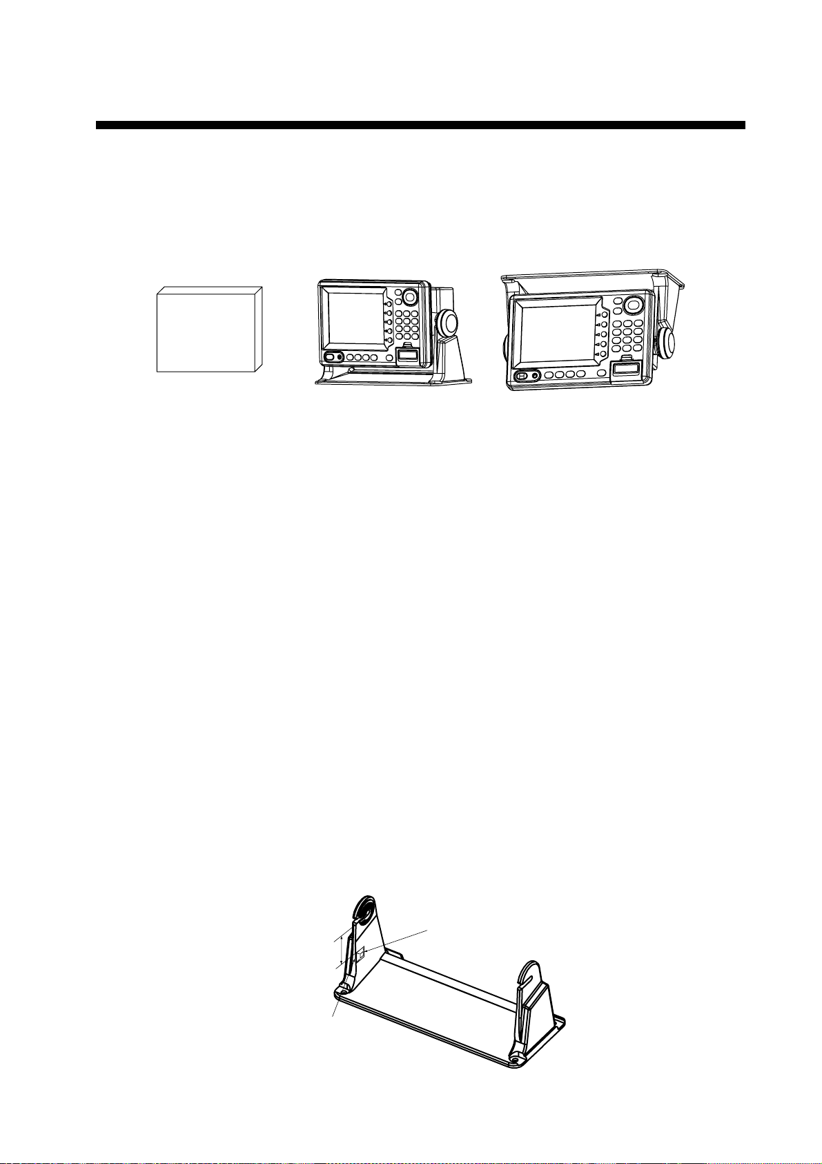
1.1 Installation of Display Unit
Mounting considerations
The dis play unit can be installed on a tabletop, on the overhead or flush mounted in a
console or p anel.
OverheadTabletopHard Cover
Tabletop, overhea d mounting methods
When select ing a mounting l oc ation for the display unit keep the following in mind:
•
Keep the display unit out of direct sunl ight.
•
The temper ature and humidity shoul d be m oderate and stable.
•
Locate the unit away fr om ex haus t pipes and vents.
•
The mounting locati on s hould be well ventilat ed.
•
Mount the unit where shock and vibration are m inimal.
•
Keep the uni t away elect r om agnetic fi eld generating equi pm ent such as motor, generator.
•
For maint enance and checking purpos es , leave suf ficient space at the sides and r ear of
the unit and leave slack i n c ables.
•
A magnetic compass will be affec ted if placed too clos e to the display unit. Observe the
following compass safe distanc es to prevent disturbance t o the magnetic c om pass:
Standard compass: 0.5 meters
St eer ing compas s : 0.3 meters
•
Rubber feet ( s upplied) which absorb vibrat ion may be attached as bel ow if vibration is a
problem. Not e however that the display unit can only be tilted within 10° from vertical
positi on when the rubber fe et are used.
Rubber foot
45 ±5 mm
Align with edge
of hanger.
TM-166 No.18 black
1-1
Page 10
1. INSTALLATION
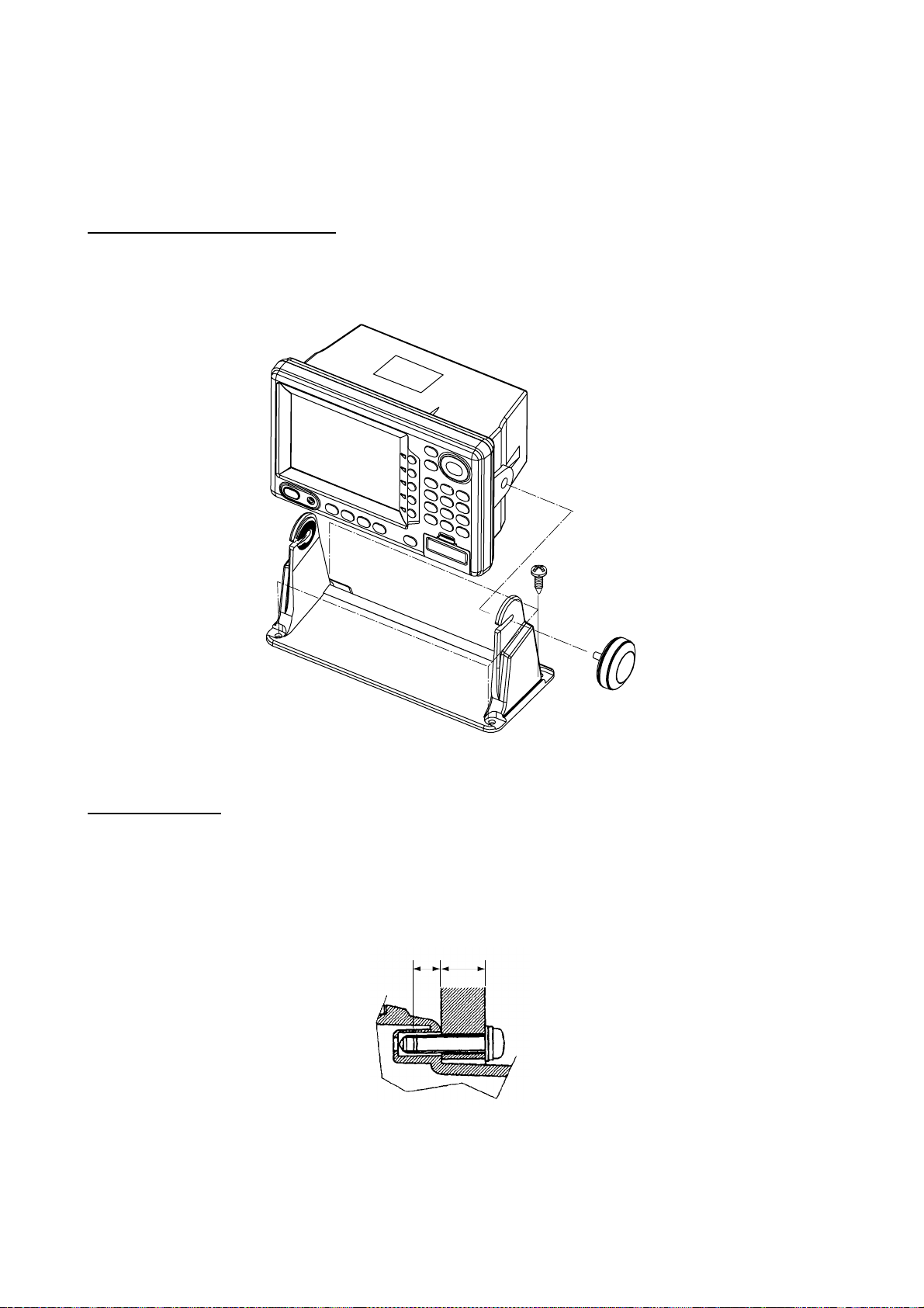
Mounting procedure
Follow the procedure below to mount the display unit on a tabletop or the overhead.
T abletop, overhead mounting
1. Fix the hanger by four tapping screws 5 X 16.
2. Screw knob bolts in display unit, set it to hanger, and tighten knob bolts.
3. Attach hard cover to protect LCD.
W
A
R
N
I
N
G
Tabletop, overhea d mounting of display unit
Flush mounting
Note: Use supplied pan head screws when the thickness of the bulkhead is from 11 to 14
mm. For bulkhead which exceeds 14 mm in thickness the length of the pan head
screws should be bulkhead thickness plus 7.3±1.5 mm. Also the length of B below
should max. 7mm.
BA
1. Prepare a cutout in the mounting location whose dimensions are as shown on the next
page.
2. Fix the display unit by six pan head screw. Refer to the outline drawing on page D-2.
1-2
Page 11
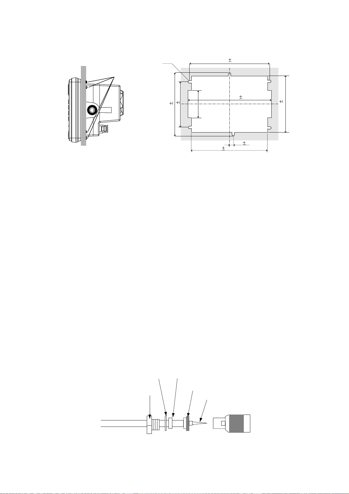
Pan head screws
6-R2.25
89 0.5
147 0.5
Cutout for flush mount
242 0.5
244 1
50
1. INSTALLATION
143 1
15 0.5
Flush mount
238 1
Flush mount ing of display unit
1.2 Installation of Antenna Unit
Mounting considerations
Install the antenna unit referring to the installation diagr am on page D-3 or D- 4. When
selecting a mounting loc ation for the ant enna unit , keep in mind the following poi nts:
•
Select a location out of the radar beam. The radar beam will obstruc t or prevent rece ption
of the GPS s atellite signal.
•
The loc ation should be w ell away from a VHF antenna. A GPS receiver i s interfered by a
harmonic wave of a VHF antenna.
•
There should be no interfering object w ithin the line-of-sight to the satelli tes. Objects
within line-of-sight to a satellit e, for example, a mast , may block reception or prolong
acquisition time.
•
Mount the antenna unit as high as possibl e. Mounting the ant enna unit as high as
possible k eeps it fr ee of interfering objects and water spray, which can i nterrupt reception
of GPS sat ellite signal if the water freezes .
•
If the antenna c able is to be p as s ed through a hole whic h is not large enough to pass the
connector, you may unfasten the connector with a needle nos e pliers and 3/8-inch
open-end wrench. Refasten it as s hown in the figure below after running the cable
through the hole.
Gasket (reddish brown)Washer
Shield
Clamp nut
Center pin (soldered)
Connector shell
How to assemble the connect or
1-3
Page 12
1. INSTALLATION
1.3 Installation of Transducers
Installing the inside-hull mount transducer
Necessary to ols
You will need the following tools:
• Sandpaper (#100)
• Silicone sealant
Remarks on instal lation
• Do the installation with the boat hauled out of the water.
• Turn off the engine while installing the equipment.
• Install the transducer in the engine room.
Selecting the mounting location
Keep the following points in mind when selecting a mounting location:
• The mounting location should be where the hull is of single-hull thickness and is void of air
or flotation materials other than solid fiberglass between the transducer face and the water.
• Do not place the transducer over hull struts or ribs which run under the hull.
• Avoid a location where the rising angle of the hull exceeds 15°, to minimize the effect of the
boat’s rolling.
• You will finalize the mounting location through some trial and error. The procedure for this is
shown later.
15 cm
15 cm
1/2
1/3
Mounting location
for transducer
Centerline
50 cm
50 cm
1-4
Inside-hull transducer mounting location
Page 13
1. INSTALLATION
Attaching the t ran sducer
1. Clean the transducer face to remove any foreign material. Lightly roughen the
transducer face with #100 sandpaper. Also, roughen the inside of the hull where the
transducer is to be mounted.
2. Warm the silicone sealant to 40°C before usage to soften it. Coat the transducer face
and mounting location with silicone sealant.
Transducer face
Silicone sealant
Coating the t r ansducer face with si licone sealant
3. Press the transducer firmly down on the hull and gently twist it back and forth to remove
any air which may be trapped in the silicone sealant.
Squeeze out
air bubbles.
Hull
Silicone
sealant
Attac hing transducer to hull with s ilicone sealant
1-5
Page 14
1. INSTALLATION
Observing the picture
1. Press the [POWER] key to turn on the display unit.
2. Press the [SNDR] key to select the sounder display.
3. Press the MODE/FREQ soft key to display the following window.
MODE/FREQ
AUTO CRUISING
AUTO FISHING
MANUAL
Mode FREQ selec tion wi ndow
4. Select MANUAL with the cursor pad.
5. Press the RETURN soft key.
6. Press the GAIN soft key to display the gain window.
GAIN
HIGH
LOW
Gain window
7. Confirm that the gain is set at 50 (midpoint).
8. Press the RETURN soft key.
9. Press the RANGE soft key.
10. Press ▲ to select “15 ft”.
50
1-6
Page 15
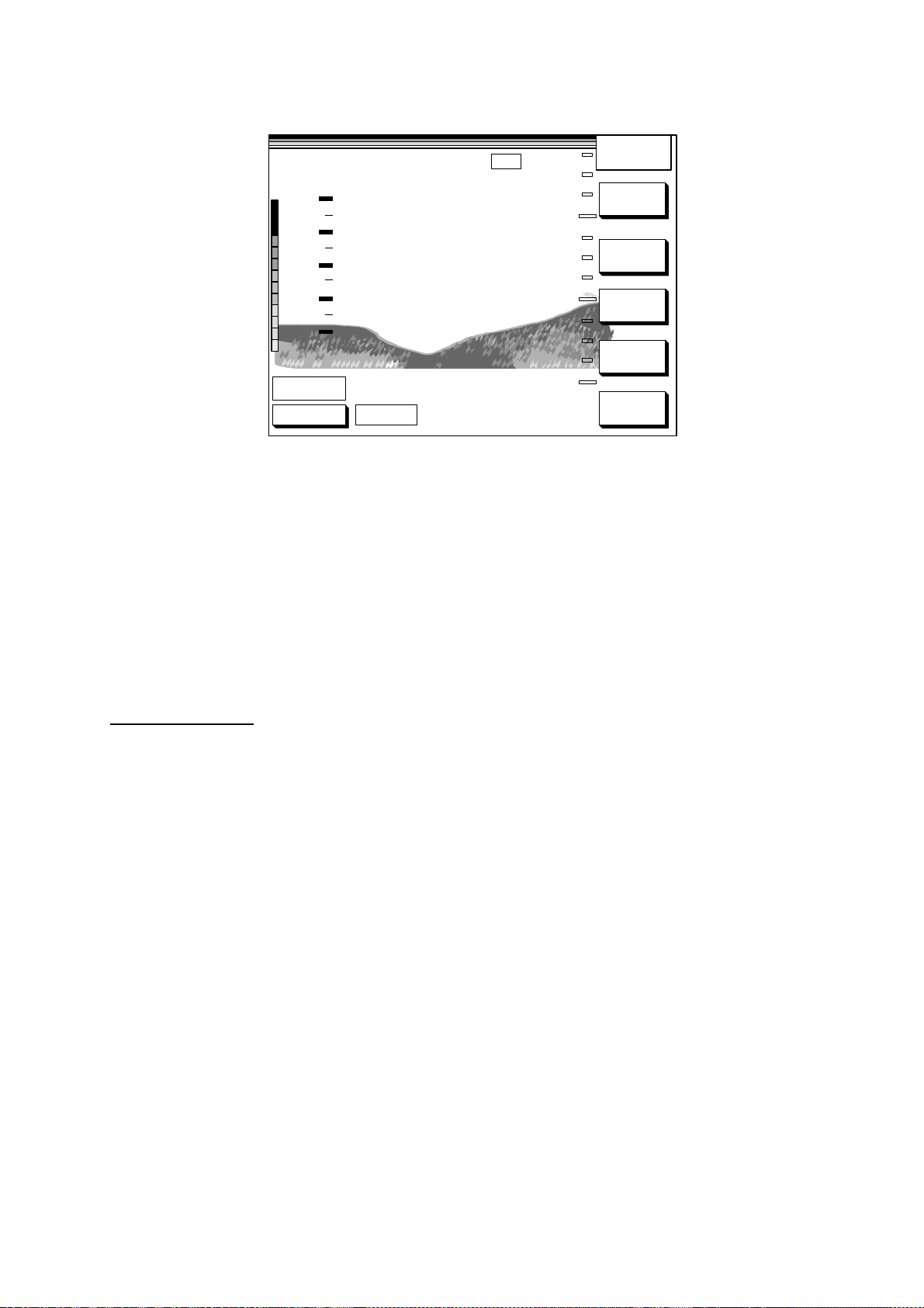
11. Press the RETURN soft key. Note the depth seabed.
1. INSTALLATION
5
10
15
SOUNDER
RANGE
GAIN
SHIFT
MODE/
FREQ
SNDR
FUNC
°C
30
20
10
0
10.2
GPS 3D
0.0
50kHz
Video sounder picture
If the bottom is displayed in reddish brown and the depth indication appears the mounting
locati on is suitable. You can leave the trans ducer in position.
If the bottom is not displayed in reddis h br own, the mounting location is unsuitable.
Relocate the transducer a nd do the following.
1. Press the [POWER] key to turn off the power.
2. Gently dismount t he transducer w ith piece of wood.
3. Do steps 1 through 5 in the previous pr oc edure. Repeat until a s uitable location is found.
Final preparation
Support t he transducer w ith a piece of wood to keep it in place while it is drying. Let the
transducer dr y 24 – 72 hours.
1-7
Page 16
1. INSTALLATION
Installing the thru-hull mount transducer
Transducer mounting location
This type of mounting provides the best performance of all, since the transducer protrudes
from the hull and the effect of air bubbles and turbulence neat the hull skin is reduced.
When the boat has a keel, the transducer should be at least 30 cm away from it. Typical
through hull mountings are shown in the figure on the next page.
The performance of the video sounder is directly related to the mounting location of the
transducer, especially for high-speed cruising. The installation should be planned in
advance, keeping the standard cable length (8 m) and the following factors in mind.
•
Air bubbles and turbulence caused by movement of the boat seriously degrade the
sounding capability of the transducer. The transducer should, therefore, be located in a
position where water flow is the smoothest. Noise from the propellers also adversely
affects performance and the transducer should not be mounted nearby. The lifting strakes
are notorious for creating acoustic noise, and these must be avoided by keeping the
transducer inboard of them.
•
The transducer must always remain submerged, even when the boat is rolling, pitching or
up on a plane at high speed.
•
A practical choice would be somewhere between 1/3 and 1/2 of the boat’s length from the
stern. For planning hulls, a practical location is generally rather far astern, so that the
transducer is always in water regardless of the planning attitude.
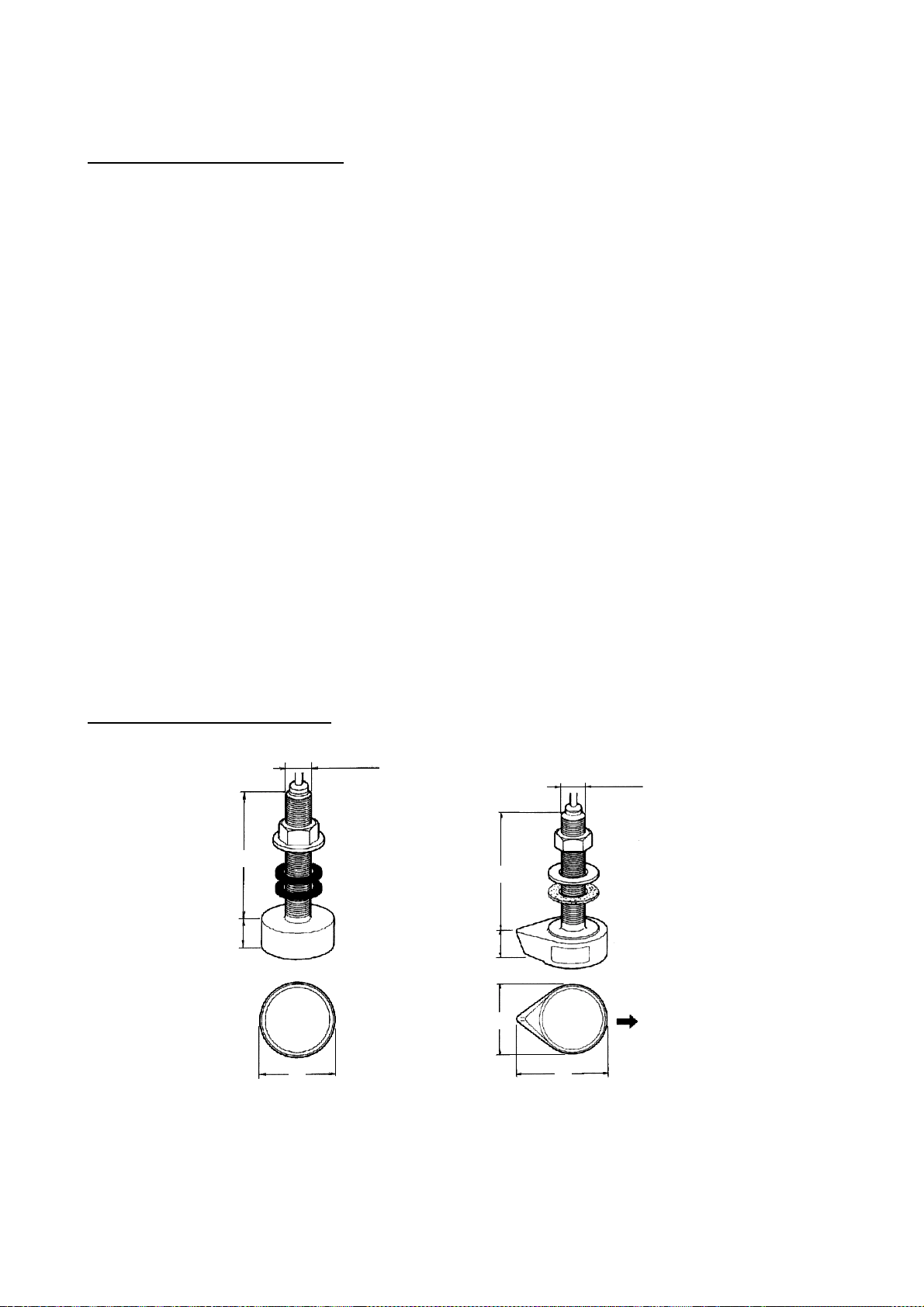
Transducer outline drawings
120
30
22
All dimensions
in millimeters
24
120
28
1-8
68
68 87
520-5PSD (option) 520-5MSD (option)
Ship's
bow
Transducer outline drawings
Page 17
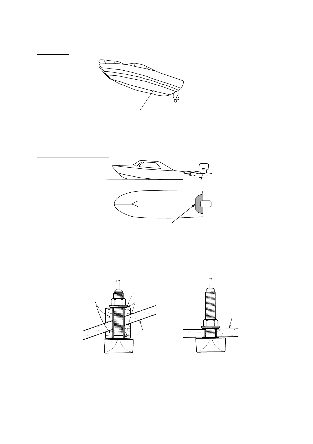
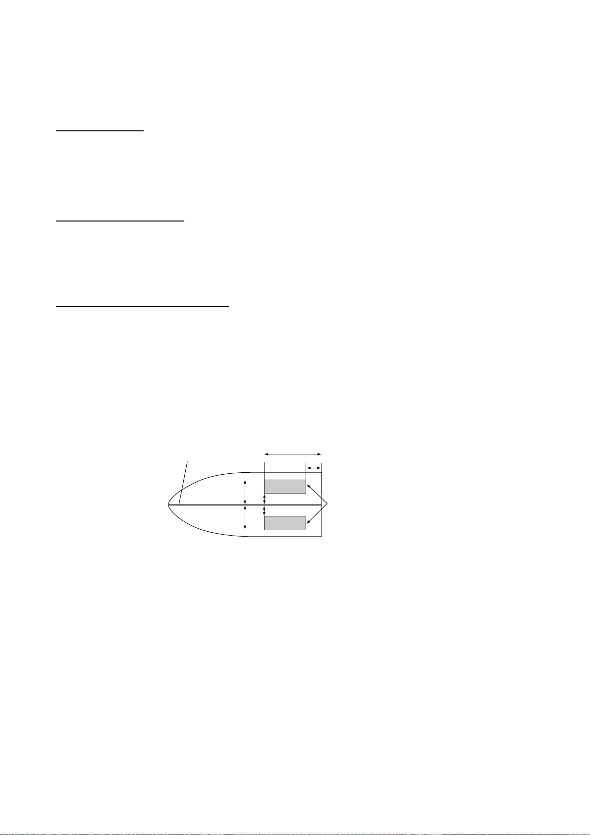
Acceptable transducer mounting locations
1. INSTALLATION
Deep-V hull
• Position 1/2 to 1/3 length of the hull from stern.
• 15 to 30 cm off center line (inside first lifting strakes.)
Transducer mounting location on deep- V hull
High speed V-planning hull
• Within the wetted bottom area
• Deadrise angle within 15°
Transducer mounting location on high s peed V-planning hull
T ypical through-hull mount transducer installations
Fairing block
Deep-V hull Flat hull
Flat washer
Rubber washer
Hull
bottom
Typical through-hul l mount transducer inst allations
Hull
bottom
1-9
Page 18
1. INSTALLATION
Procedure for installing the thru-hull mount transducer
1. With the boat hauled out of the water, mark the location selected for mounting the
transducer on the bottom of the hull.
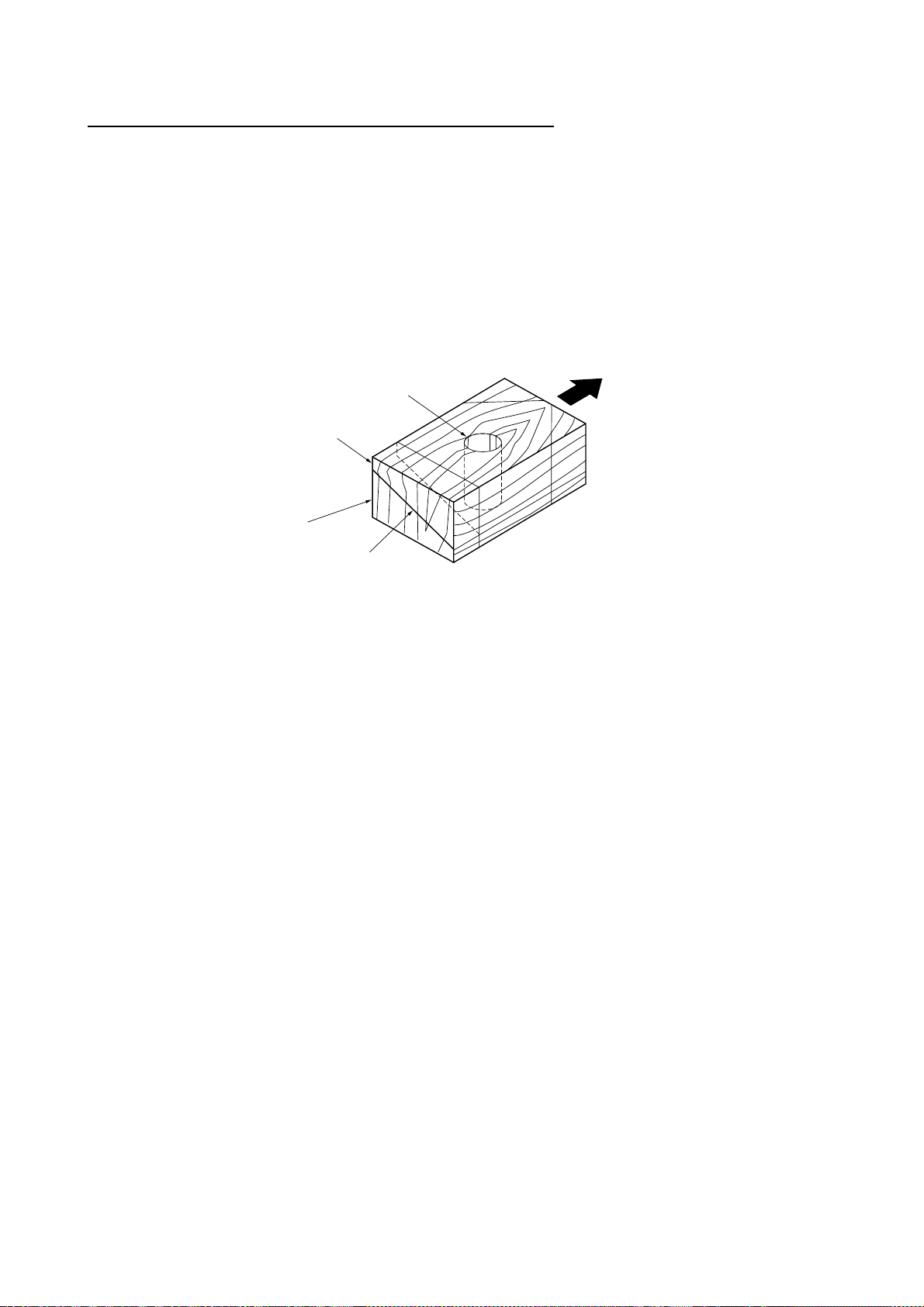
2. If the hull is not level within 15° in any direction, faring blocks made out of teak should
be used between the transducer and hull, both inside and outside, to keep the
transducer face parallel with the water line. Fabricate the fairing block as shown below
and make the entire surface as smooth as possible to provide an undisturbed flow of
water around the transducer. The fairing block should be smaller than the transducer
itself to provide a channel to divert turbulent water around the sides of the transducer
rather than over its face.
Hole for
stuffing tube
Upper half
Lower half
Saw along slope
of hull.
Bow
Construction of fairing block
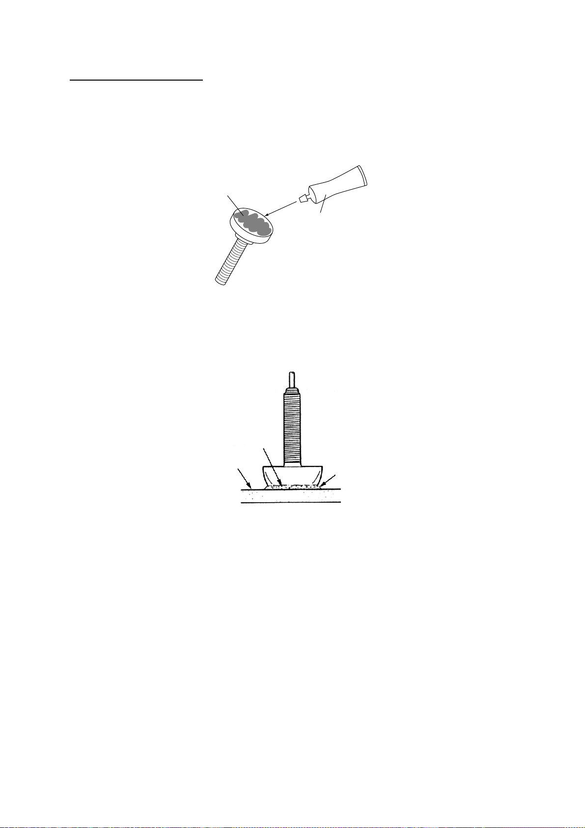
3. Drill a hole just large enough to pass the threaded stuffing tube of the transducer
through the hull, making sure it is drilled vertically.
4. Apply a sufficient amount of high quality caulking compound to the top surface of the
transducer, around the threads of the stuffing tube and inside the mounting hole (and
fairing blocks if used) to ensure watertight mounting.
5. Mount the transducer and fairing blocks and tighten the locking nuts. Be sure that the
transducer is properly oriented and its working face is parallel to the waterline.
Note: Do not over-stress the stuffing tube and locking nuts through excessive tightening,
since the wood block will swell when the boat is placed in the water. It is suggested
that the nut be tightened lightly at installation and retightened several days after the
boat has been launched.
1-10
Page 19
1. INSTALLATION
Installing the transom mount transducer
This type of mounting is very commonly employed, usually on reactively small I/O or
outboard boats. Do not use this method on an inboard motor boat because turbulence is
created by the propeller ahead of the transducer.
There are two methods of installation: flush with hull (for flat hulls) and projecting from hull
(for deep V-hulls).
D
D>50 cm
Deep-V
Flat hull
hull
Transom mount transducer mounting locations
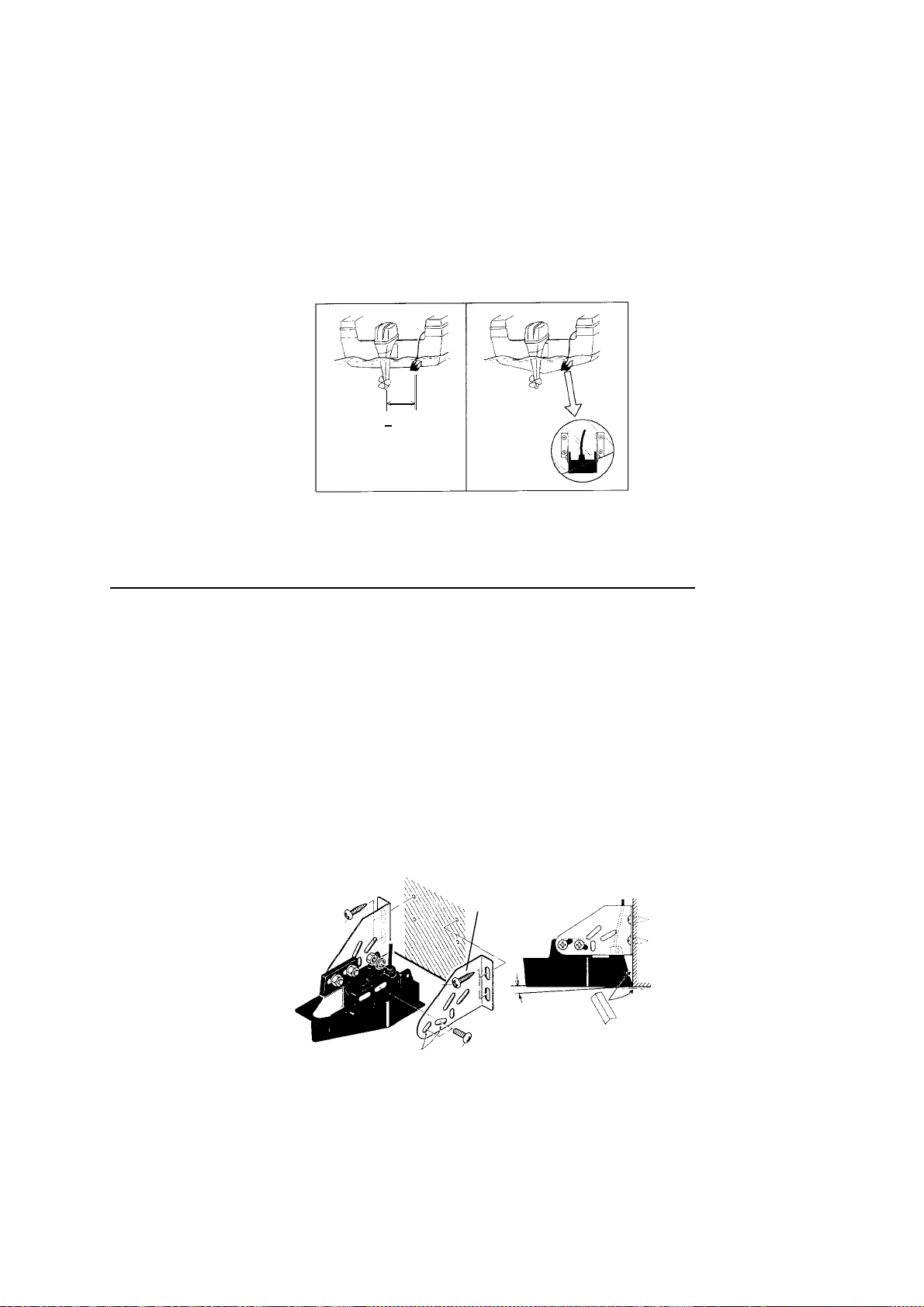
Installing the transom mount transducer flush with hull (for flat hulls)
A suitable mounting location is at least 50 cm away from the engine and where the water
flow is smooth.
1. Drill four pilot holes in the mounting location.
2. Attach the transducer to the bracket with tapping screws (supplied).
3. Adjust the transducer position so the transducer faces right to the seabed.
Note: If necessary, to improve water flow and minimize air bubbles staying on the
transducer face, incline the transducer about 5° at the rear. This may require a
certain amount of experimentation for fine tuning at high cruising speeds.
4. Fill the gap between the wedge front of the transducer and transom with epoxy material
to eliminate any air spaces.
M5 x 20
M5 x 20
5˚
Tape
No.1
M5 x 14
Transom mount transducer, mounti ng flush with hull
1-1 1
Page 20
1. INSTALLATION
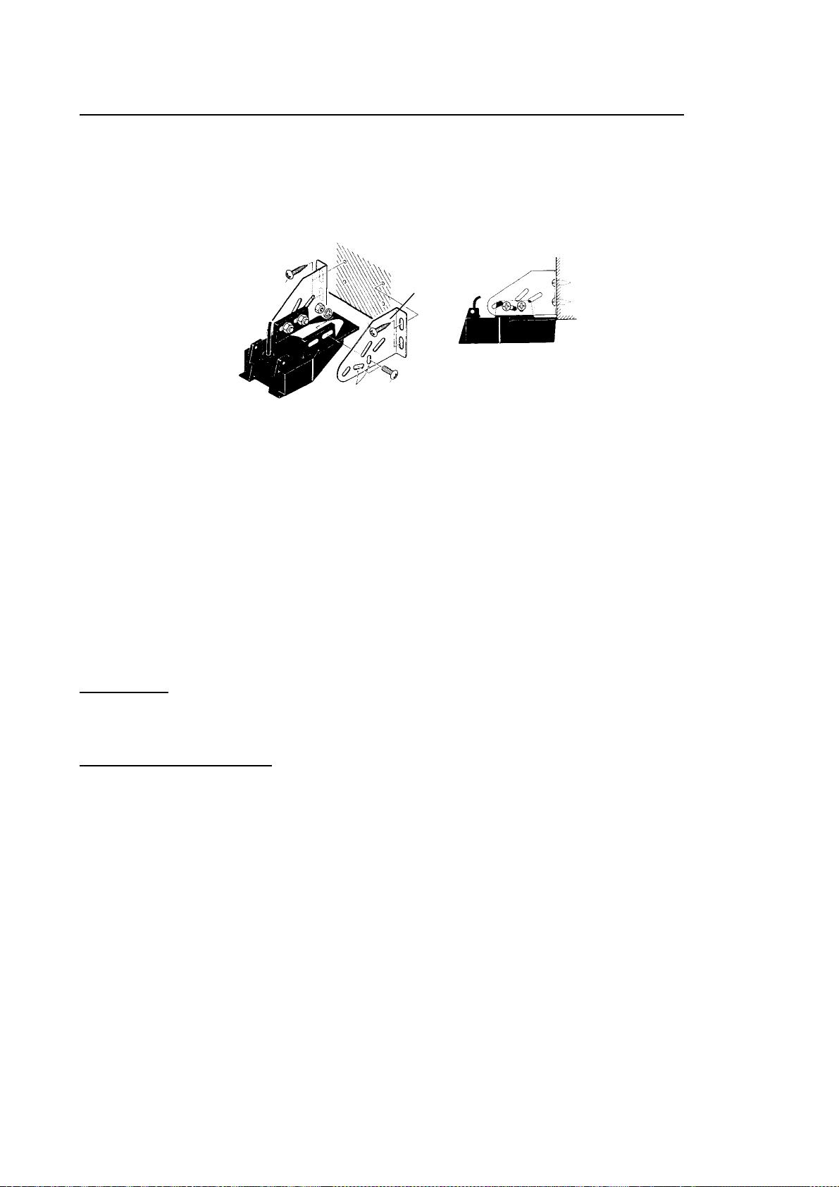
Installing the transom mount transducer projecting from hull (for deep-V hulls)
This method is employed on deep-V hulls and provides good performance because the
effects of air bubbles are minimal. Install the transducer parallel with water surface; not flush
with hull. If the boat is placed on a trailer care must be taken not to damage the transducer
when the boat is hauled out of the water and put on the trailer.
M5 x 20
No. 2
M5 x 20
M5 x 14
Transom mount transducer, projecting from hull
Transducer preparation
Before putting the boat in water, wipe the face of the transducer thoroughly with a detergent
liquid soap. This will lessen the time necessary for the transducer to have good contact with
the water. Otherwise the time required for complete “saturation” will be lengthened and
performance will be reduced.
Do not paint the transducer. Performance will be affected.
Triducer
525ST-MSD
The triducer is designed for thru-hull mounting.
Mounting considerations
When selecting a mounting location keep the following points in mind:
•
Air bubbles and turbulence caused by movement of the boat seriously degrade the
sounding capability of the transducer. The transducer should, therefore, be located in a
position where water flow is the smoothest. Noise from the propellers also adversely
affects performance and the transducer should not be mounted nearby. The lifting strakes
are notorious for creating acoustic noise, and these must be avoided by keeping the
transducer inboard of them.
•
The transducer must always remain submerged, even when the boat is rolling, pitching or
up on a plane at high speed.
•
A practical choice would be somewhere between 1/3 and 1/2 of the boat’s length from the
stern. For planning hulls, a practical location is generally rather far astern, so that the
transducer is always in water regardless of the planning attitude.
1-12
Page 21
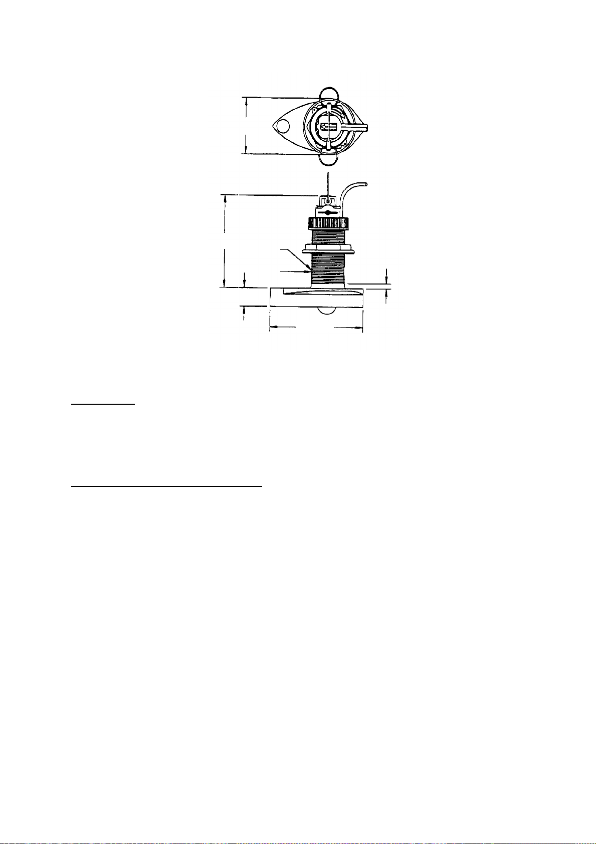
φ79 mm
133 mm
2.00"-12 UN
threads
1. INSTALLATION
7 mm
φ51 mm
27 mm
140 mm
Dimensions of triducer 525S T-MSD
525ST-PWD
The Transom Mount Transducer or TRIDUCER
®
Multisensor with Integral Release Bracket
525ST-PWD is manufactured by AIRMAR Co. These instructions are included with the
sensor.
Pre-test for speed and temp erature
Connect the sensor to the instrument and spin the paddlewheel. Check for a speed reading
and the approximate air temperature. If there is no reading, return the sensor to your place
of purchase.
1-13
Page 22
1. INSTALLATION
Tools and materials needed
Scissors
Masking tape
Safety goggles
Dust mask
Electric drill
Drill bit for:
Bracket holes: 4mm, #23, or 9/64”
Fiberglass hull: chamfer bit (preferred),
6mm, or 1/4”
Transom hole: 19mm or 3/4” (optional)
Cable clamp holes: 3mm or 1/8”
Screwdrivers
Straight edge
Marine sealant
Pencil
Zip-ties
Water-based antifouling paint (mandatory in salt water).
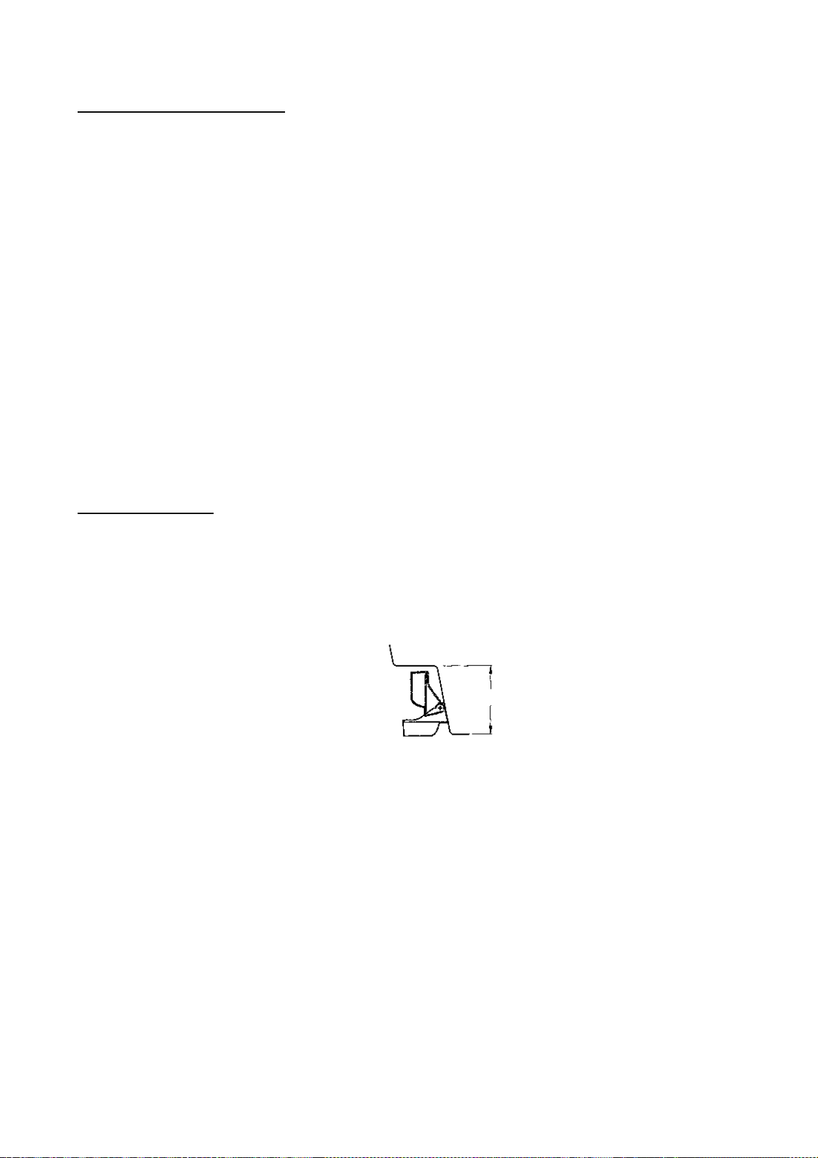
Mounting location
To ensure the best performance, the sensor must be submerged in aeration-free and
turbulence-free water. Mount the sensor close to the centerline of the boat. On slower
heavier displacement hulls, positioning it farther from the centerline is acceptable.
Allow adequate space above the bracket for it to release and rotate the sensor upward.
Height without
speed sensor
191mm (7-1/2")
Height with
speed sensor
213mm (8-1/2")
Height
Height req uired at mount ing location
Note 1: Do not mount the sensor in an area of turbulence or bubbles: near water intake or
discharge openings; behind strakes, struts, fittings, or hull irregularities; behind eroding
paint (an indication of turbulence).
Note 2: Avoid mounting the sensor where the boat may be supported during trailering,
launching, hauling, and storage.
Note 3: For single drive boat, mount on the starboard side at least 75 mm
(3”) beyond the swing radius of the propeller.
1-14
Page 23

1. INSTALLATION
75 mm(3")
minimum beyond
swing radius
Mounti ng loc ation on singl e drive boat
Note 4: For twin drive boat, mount between the dr ives.
Installation o f bracket
1. Cut out the installation template shown on the left.
2. At t he s elected locat ion, position t he template, so the arr ow at the bottom is aligned w ith
the bottom edge of the transom. B eing sure the t em plate is p ar allel to the water line, tape
it in place.
Installation template
for starboard side of boat
Drill at locations labeled "B"
for the following transom angles:
°
through 22
16
Drill at locations labeled "A"
for the following transom angles:
2
°
through 15
Align arrow with bottom of transom
°
BBB
AAA
°
Align template vertically.
Deadrise angle
Slope of hull
parallel to
waterline
Align template arrow with
bottom edge of transom.
Positioning the template
Warning: Always wear s af ety goggles and a dust mask.
1-15
Page 24

1. INSTALLATION
3. Using a 4 mm, #23, or 9/64” bit, drill three holes 22 mm (7/8”) deep
at the locations indicated. To prevent drilling too deeply, wrap masking tape around the
bit 22 mm (7/8”) from the point.
Fiberglass hull: Minimize surface cracking by chamfering the gelcoat. If a chamfer bit
or countersink bit is not available, start drilling with a 6mm or 1/4” bit to a depth of 1 mm
(1/16”).
4. If you know your transom angle, the bracket is designed for a standard 13° transom
angle.
11°-18° angle: No shim is required. Skip to step 3 in “Adjusting”.
Other angles: The shim is required. Skip to step 2 of “Adjusting”.
If you do not know the transom angle, temporarily attach the bracket and sensor to the
transom to determine if the plastic shim is needed.
5. Using the two #10 x 1-1/4” self-tapping screws, temporarily screw the bracket to the hull.
DO NOT tighten the screws completely at this time. Follow the step 1-4 in “Attaching the
Sensor to the Bracket”, before proceeding with “Adjusting”.
Adjusting
1. Using a straight edge, sight the underside of the sensor relative to the underside of the
hull. The stern of the sensor should be 1-3 mm (1/16-1/8”) below the bow of the sensor
or parallel to the bottom of the hull.
2°-10°
transom
angle
shim with
taper down
angle
reversed
11° transom angle
NO SHIM
YES YESYES
parallelparallel parallel
12-18° transom angle
NO SHIM
NO
YES NO
slight
angle
19°-22°
transom
angle
shim with
taper up
angle
too steep
Sensor position and transom angle
Note: Do not position the bow of the sensor lower than the stern because aeration will
occur.
1-16
Page 25

1. INSTALLATION
2. To adjust the sensor’s angle relative to the hull, use the tapered plastic shim provided. If
the bracket has been temporarily fastened to the transom, remove it, Key the shim in
place on the back of the bracket.
2°-10° transo m angle (stepped transom and jet boats): Position the shim with the
tapered end down.
19°-22° transom angle (small alumin um and fibergl ass boats) :
Position the shim with the tapered end up.
3. If the bracket has been temporarily fastened to the transom, remove it. Apply a marine
sealant to the threads of the two #10 x 1-1/4” self tapping screws to prevent water
seeping into the transom. Screw the bracket to the hull. Do not tighten the screws
completely at this time.
4. Repeat step 1 to ensure that the angle of the sensor is correct.
Note: Do not position the sensor farther into the water than necessary to avoid
increasing drag, spray, and water noise and reducing boat speed.
5. Using the vertical adjustment space on the bracket slots, slide the sensor up or down to
provide a projection of 3 mm (1/8”). Tighten the screws.
Cable cover
Cable
clamp
50 mm (2")
Hull projection 3 mm (1/8")
Vertical adjustment and cable routing
1-17
Page 26

1. INSTALLATION
Attaching the sensor to the bracket
1. If the retaining cover near the top of the bracket is closed, open it by depressing the
latch and rotating the cover downward.
Step 1
Retaining
cover
Step 3
Step 2
Latch
Pivot
arm (2)
Slot (2)
Step 4
Attac hing the sensor to t he br ac ket
2. Insert the sensor’s pivot arms into the slots near the top of the bracket.
3. Maintain pressure until the pivot arms click into place.
4. Rotate the sensor downward until the bottom snaps into the bracket.
5. Close the retaining cover to prevent the accidental release of the sensor when the boat
is underway.
1-18
Page 27

1. INSTALLATION
Cable routing
Route the sensor cable over the transom, through a drain hole, or thorough a new hole
drilled in the transom above the waterline.
Never cut the cable or remote the connector; this will void the warranty.
Always wear safety goggles and a dust mask.
1. If a hole must be drilled, choose a location well above the waterline. Check for
obstructions such as trim tabs, pumps, or wiring inside the hull. Mark the location with a
pencil. Drill a hole through the transom using a 19 mm or 3/4” bit (to accommodate the
connector).
2. Route the cable over or through the transom.
3. On the outside of the hull secure the cable against the transom using the cable clamps.
Position a cable clamp 50 mm(2”) above the bracket and mark the mounting hole with a
pencil.
4. Position the second cable clamp halfway between the first clamp and the cable hole.
Mark this mounting hole.
5. If a hole has been drilled in the transom, open the appropriate slot in the transom cable
cover. Position the cover over the cable where it enters the hull. Mark the two mounting
holes.
6. At each of the marked locations, use a 3 mm or 1/8” bit to drill a hole 10 mm (3/8”) deep.
The prevent drilling too deeply, wrap masking tape around the bit 10 mm (3/8”) from the
point.
7. Apply marine sealant to the threads of the #6 x 1/2” self-tapping screw to prevent water
from seeping into the transom. If you have drilled a hole through the transom, apply
marine sealant to the space around the cable where it passes through the transom.
8. Position the two cable clamps and fasten them in place. If used, push the cable cover
over the cable and screw it in place.
9. Route the cable to the instrument being careful not to tear the cable jacket when passing
it though the bulkhead(s) and other parts of the boat. To reduce electrical interference,
separate the sensor cable from other electrical wiring and “noise” sources. Coil any
excess cable and secure it in place with zip-ties to prevent damage.
1-19
Page 28

1. INSTALLATION
1.4 Installation of Sensors
Transom mount water temperature sensor T-02MTB
•
Fix the cable at a convenient location with cable clamp.
•
When the cable is led in through the transom board, make a hole of approx. 17 mm
diameter to pass the connector. After passing the cable, fill the hole with a sealing
compound.
D
D>50 cm
M5 x 20
Mount sensor
flush with hull bottom.
How to ins tall transom mount wat er temperature sens or T-02MTB
1-20
Page 29

1. INSTALLATION
Thru-hull mount water temperature sensor T-02MSB, T-03MSB
Select a suitable m ounting location consideri ng the following points :
•
Select a mid-boat flat position. The sensor does not have to be installed perfectly
perpendicular. The sensor m us t not be damaged in dry-docking operation.
•
Select a place apart fr om equipment generating heat.
•
Select a place in the forward direction vi ewing from t he dr ain hole, to allow for ci r c ulation
of cooli ng water.
•
Select a place free from vibr ation.
T-02MSB T-03MSB
Sensor Holder
Sensor
cable
Locknut
Washer
Gasket
φ21 mm
Coat with
sealant.
Mounting procedure
1. Drill a hole of 21 mm in diameter in
the mounting location.
2. Pass the sensor cable through the
hole.
3. Pass gasket, washer and locknut
onto cable in that order.
4. Coat the sensor flange with high
quality sealant and then fasten the
sensor with the locknut.
(Torque: max. 59N·m)
5. Launch the boat to check for water
leakage around the sensor.
Locknut
Locknut
Washer
Gasket
φ25 mm
Coat with
sealant.
Plate thickness
Holder Guide
within 25 mm
Mounting procedure
1. Drill a hole of 25 mm in diameter in the mounting
location.
2. Coat holder guide with high quality sealant, and
pass gasket, washer and locknut onto holder
guide in that order and then tighten the locknut.
3. Set the sensor holder to the holder guide from
inside the boat and then tighten the locknut.
4. Launch the boat to check for water leakage
around the sensor.
Thru-hull mount water temperature sens or s T-02MSB, T-03MSB
1-21
Page 30

1. INSTALLATION
Thru-hull mount water temperature/speed sensor ST-02MSB,
ST-02PSB
Select a suitable m ounting location consideri ng the following:
•
Select a mid-boat flat position. The sensor does not have to be installed perfectly
perpendicular. The sensor m us t not be damaged in dry-docking operation.
•
Select a place apart fr om equipment generating heat.
•
Select a place in the forward direction vi ewing from t he dr ain hole, to allow for ci r c ulation
of cooli ng water.
•
Select a place free from vibr ation.
1. Dry - doc k the boat.
2. Mak e a hole of approx. 51 mm diameter.
3. Unfast en locknut and remove the sensor section.
4. Apply high-grade sealant to the f lange of the sens or.
5. Pass t he s ens or casing thr ough the hole.
6. Face t he notch on the sensor towar d boat’s bow and t ighten the fl ange.
7. Set t he s ens or s ec tion to the sensor casing an d tighten the locknut.
8. Launch the boat and ch ec k for wat er leakage around the sensor.
Locknut
Face "notch"
toward bow.
Brim
51
φ
123
77
Flange nut
Coat with
silicone sealant.
Water temperature/speed sensor ST-02MSB, ST-02PSB
1-22
Page 31

2. WIRING
ANT XDR
TEMP/SPD
DGPS
NMEA
+ GND
1 3
2
-
12 - 24
VDC
Antenna unit
GPA-017
(GP-1850WF)
Display unit (back)
Transducer
Speed/
Temperature
(Option)
DGPS beacon receiver
(option for GP-1850WF,
RS-232C only)
External
equipment
Black
White
Shield
Ground
Earth terminal
GPA-019
(GP-1850WDF)
All wiring are terminated at the rear of t he display unit.
Display unit, rear view
Power cable
Connect the power cable to the pow er c onnec tor . Connect the leads to the battery (12 or 24
VDC); white to plus(+ ) term inal and black to minus(-) terminal.
Cable connector
Power cable
w/fuse (5A)
Lead wire
Black
BATTERY
Connecti ng the power cable t o the battery
White
2-1
Page 32

2. WIRING
Antenna unit
Connect the antenna cabl e to the ANT connector.
Transducer
Connect the transducer cable to the XDR connector.
Water temperature/speed sensor
Connect the water temperature sens or ( option) or water temperature/speed s ens or (option)
to the T E MP/SPD connector.
Ground
The dis play unit cont ains several CPUs. While they are operating, they radiate noise, which
can interf er e with radi o equipment. Ground the unit t o pr eve nt interferenc e. The grounding
wire should be 1.25 sq or larger and as short as pos s ible. Connect the groundi ng wire to
ship's ground. On a fi berglass boat, it is best to install a ground plate that measures about
20 cm by 30 cm on the outside of the hull bot tom to provide a ground point. I f t his is not
practical, the engine block can be used.
CAUTION
Ground the equipment to
prevent electrical shock
and mutual interference.
Note: Use a “closed” lug t o m ak e the ground connection at the display unit. Do not use an
“open-type” lug (
Extendin g an te nn a c ab le le ng th
The standard cable is 10 m long. For extens ion, in case of the GPA-019S or GPA-017S, an
antenna cabl e s et of 15 m, 30 m or 50 m is available. E x tension cable cannot be used w ith
the GPA-017 or GPA-019.
Cable length Necessary part s Code No.
15 m TNC-PS-3D-15 000-133-670
30 m CP 20-01700 004-372-110
50 m CP 20-01710 004-372-120
).
2-2
Page 33

2. WIRING
Extension cable lin e- up (in case of 15 m, 30 m or 50 m)
Fabricat e the end of the antenna cable and at tach the coaxial connector. Detai ls are show n
on next pag e.
Antenna unit
GPA-019S/GPA-017S
Conversion
cable assy.
: Connector
1 m
Antenna cable
30 m or 50 m 1 m
Fabricate locally. (See next page.)
To display unit
Cable ext ens ion (CP20-01 700, CP20-01710)
Antenna unit
GPA-019S/GPA-017S
: Connector
Antenna cable
15 m
To display unit
Cable ext ens ion (TNC-PS-3D-15)
Waterproofing connector
Wrap connector wi th vulcanizing tape and then vinyl tape. Bind the tape end with c able-tie.
Waterpr oofing connect or
2-3
Page 34

2. WIRING
How to att ach the N-P-8DFB connector
Outer sheath
Cover with heat-shrink tubing and heat.
Armor
30
Clamp
nut
Dimensions in millimeters.
Inner sheath shield
50
Gasket
(reddish
brown)
30
10
Clamp
Aluminum foil
Remove outer sheath and armor by the dimensions
shown left.
Expose inner sheath and shield by the dimensions
shown left.
Cut off insulator and core by 10mm.
Twist shield end.
Ship on clamp nut, gasket and clamp as shown left.
Trim shield here.
Clamp nut
Insulator
Trim aluminum
tape foil here.
1
5
Pin
Shell
Fold back shield over clamp and trim.
Cut aluminum foil at four places, 90° from one
another.
Fold back aluminum foil onto shield and trim.
Expose the insulator by 1mm.
Expose the core by 5mm.
Slip the pin onto the conductor. Solder them together
through the hole on the pin.
2-4
Insert the pin into the shell. Screw the clamp nut into
the shell.
Solder through
the hole.
(Tighten by turning the clamp nut. Do not tighten by
turning the shell.)
Fabricat ion of coaxial cable
Page 35

3. INITIAL SETTINGS
3.1 NMEA Setting
NMEA port
This setting should be done when connecting with other equipment, autopilot, radar or
remote display.
1. Press the [MENU] key.
2. Press the CONFIGURATION soft key.
3. Press the SETUP NMEA PORT1 soft key.
4. Press the cursor pad to select FORMAT.
5. Press the EDIT soft key to display the following window.
▲
DGPS 3D
Output for mat window (PORT 1)
6. Select NMEA version depending on the specification of the equipment connected. The
selected item is indicated by black button.
7. Press the ENTER soft key.
8. Press the [PLOT] key to return to the plotter display.
OUTPUT FORMAT
▲
NMEA0183 Ver1.5
NMEA0183 Ver2.0
▼
SETUP
PORT1
ENTER
CANCEL
3-1
Page 36

3. INITIAL SETTINGS
DGPS port
Set the following when c onnec ting with DGPS beacon receiver GR-80 or t he DGPS beacon
receiver is incorporated, PC to the DGPS por t.
Note: Signal level for DGPS port i s RS 232C.
1. Press the [MENU] key.
2. Press the CONFIG URATION s oft key.
3. Press the SETUP NMEA/DGPS PORT 2 soft key.
4. Select FORMAT, and then press the EDIT soft key.
The following window appears.
▲
FORMAT NMEA 0183
DGPS 3D
OUTPUT FORMAT
▲
NMEA0183 Ver1.5
NMEA0183 Ver2.0
RTCM104 (EXTRN)
RTCM104 (INTRN)
RTCM104 (OUTPUT)
▼
VER 1.5
▲▲▲
SETUP
PORT2
ENTER
CANCEL
Output for mat window (PORT 2)
5. Select NMEA version. The selected item is indicated by black button.
NMEA0183 Ver1.5/2.0: Select one when connecting PC or RS-232C equipment.
RTCM104 (EXTERN): Select this when connecting external DGPS beacon receiver.
RTCM104 (INTRN): Select this for built in internal DGPS beacon receiver.
RTCM104 (OUTPUT): Select this when outputting differential data of the internal
DGPS beacon receiver to other GPS navigator.
Note 1: Note that you cannot setup sentenc es when you select RT CM104 at the format.
Note 2: For RS- 422 format, the level conve r ter (IF-1432) is required for c onnection of
external equipment.
6. Press the ENTER soft key.
7. Press the [PLOT] key to finish.
3-2
Page 37

3. INITIAL SETTINGS
3.2 Output Data Sentences
Select out put data sentences for external equipment as follow s.
1. Press the [MENU] k ey.
2. Press the CONFI GURA TION soft key.
3. Press the SETUP NMEA PORT1 soft key.
4. Press the SELECT SNT NC. soft key to display the SELECT SENT ENCE window.
▲
DGPS 3D
SELECT SENTENCE
▲
AAM
APB ON
BOD
BWR*
DPT**
GGA
GLL ON
MTW
RMA
RMB ON
RMC ON
VTG ON
WPL
XTE
ZDA ON
*: BWR for Rhumb line
BWC for Great circle
**: DPT for NMEA0183 Ver. 2.0
DBT for NMEA0183 Ver. 1.5
Select sentence window
5. Selec t data sentence you want to output.
6. Press the ON/OFF s oft key. To output data, select ON.
7. Repeat to select other s entences.
8. Press the RETURN soft key .
9. Press the [PLOT ] key to return the plotter displ ay.
SELECT
SNTNC.
ON/OFF
RETURN
3-3
Page 38

3. INITIAL SETTINGS
Input/Output data sentences
Port Format Data Remarks
Input
NMEA-0183
NMEA
Output
Input
DGPS
Output
*: Cannot be input consecutively.
**: Output automatically when LC or LA is selected.
Ver. 2.0
Ver. 1.5
IEC601162-1
NMEA-0183
Ver. 2.0
Ver. 1.5
RS232C
RTCM104
TLL*, MTW, WPL* WPL: GP only
AAM, APB, BOD, BWC/BWR,
GGA, GLL, RMA, RMB, RMC,
VTG, WPL, XTE, ZDA, DBT/DPT,
MTW, GTD**
TLL*, MTW, WPL*, DBT/DPT
AAM, APB, BOD, BWC/BWR,
GGA, GLL, RMA, RMB, RMC,
VTG, WPL, XTE, ZDA, DBT/DPT,
MTW, GTD**
3.3 Antenna Height
Enter height of antenna above water. (Default setting: 5 m)
1. Press the [MENU] k ey.
2. Press the GPS/DGPS/TD OPTIONS soft key.
3. Press the GPS SETUP OPTIO NS soft key.
4. Select ANT. HEIGHT.
5. Press the EDIT soft key.
GREAT CIRCLE: BWC
RHUMB LINE: BWR
NMEA Ver 1.5: DBT
NMEA Ver 2.0: DPT
ylnoPG:LPW
GREAT CIRCLE: BWC
RHUMB LINE: BWR
NMEA Ver 1.5: DBT
NMEA Ver 2.0: DPT
ANT. HEIGHT
0 0 5 m
Ant. height window
6. Enter the height (3 di gits) of the antenna above s ea level using the numeric keys.
If you enter wrong antenna height, press the CLEAR soft key.
7. Press the ENTER soft key.
8. Press the [PLOT ] key to return the plotter display .
3-4
Page 39

3. INITIAL SETTINGS
3.4 DGPS Setting
When extern al DGPS beacon r ec eiver (RS-232C only ) is c onnec ted or the DGPS b eac on
receiver is incorporated, set the DGPS m ode referring to the following procedur e.
1. Press the [MENU] k ey.
2. Press the GPS/DGPS/TD OPTIONS soft key.
3. Press the DGPS/WAAS SET UP OPTIONS soft key.
FORMAT NMEA 0183
DGPS/WAAS MODE OFF
BEACON FREQUENCY AUTO
BEACON BAUD RATE AUTO
WAAS SEARCH AUTO
CORRECTIONS DATA SET 02
DGPS/WAAS ALARM ON
DGPS 3D
VER 1.5
DGPS
WAAS
EDIT
RETURN
DGPS/WAAS opti ons window
4. Select DG PS/WAAS MODE and press the EDIT soft key.
5. Selec t DGPS or AUTO and press the ENTER soft key.
WAAS: W AAS data can be received.
AUTO: DGPS, WAAS or GPS dat a can be automatically received, The order of priority is
DGPS, WAAS and GPS.
Note: If the external DGPS beacon receiver GR-80 is c onnected to the G P - 1850WF, refer
to the int er c onnec tion diagr am below.
Connecti on with GR-80
GP-1850WF
DGPS
GR-80
DATA
(Set RS-232C)
> 1 >
> 2 >
RD
> 3 >
YEL
< 1 < TD-B
> 4 >
SD
SG
> 5 >
> 6 >
RED
BLU
< 3 < RD-B
< 7 < GND
> 7 >
MJ-A7SPF0003-050 cable
(option)
3-5
Page 40

3. INITIAL SETTINGS
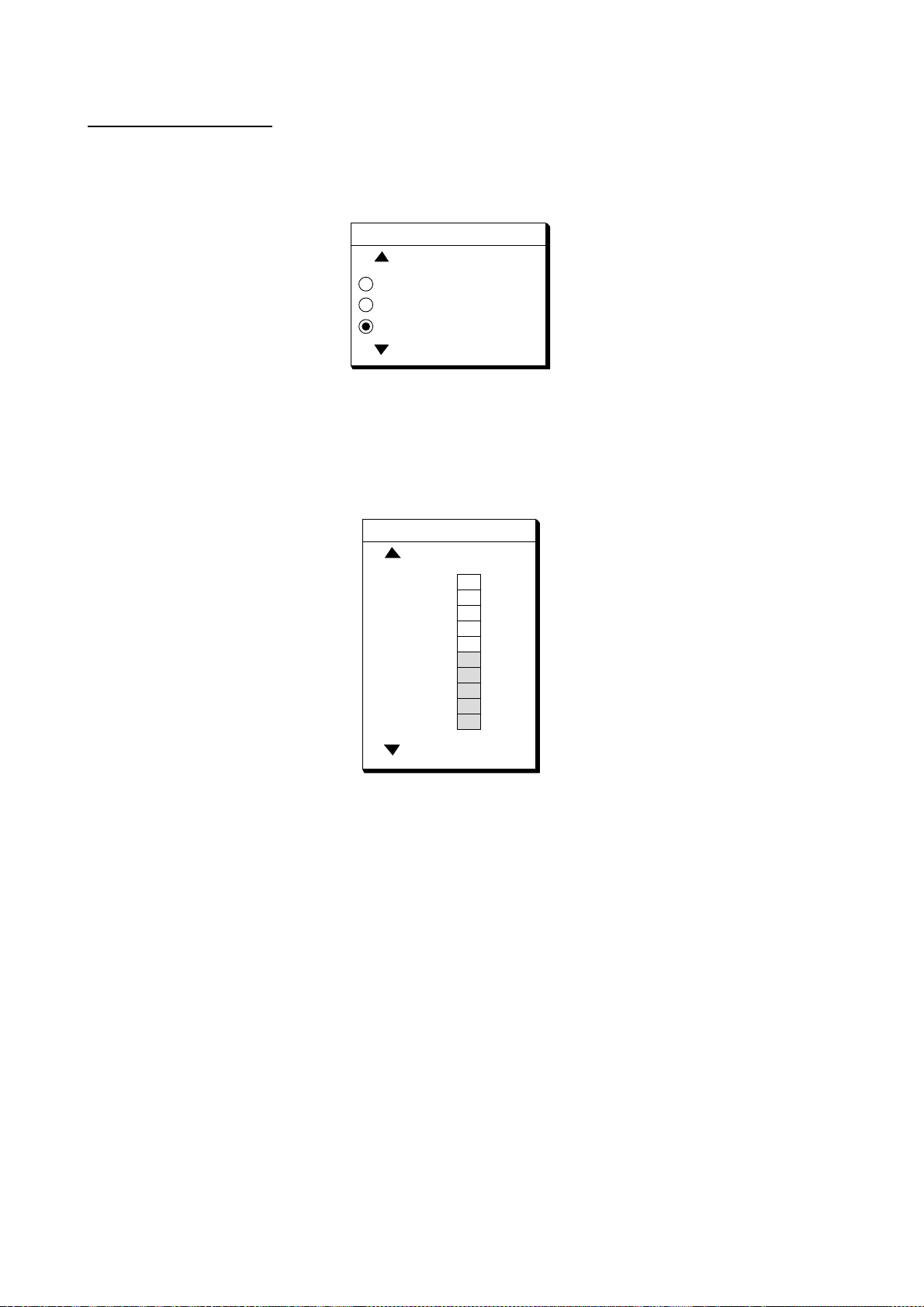
6. Select BEACON FREQUENCY by the cursor pad.
7. Press the EDIT soft key to dis play the following window.
BEACON FREQUENCY
▲
AUTO
MANUAL 284.0 kHz
▼
▼
Beacon frequency window
8. Selec t A UTO or MANUAL by the curs or pad. When you select MANUAL, operate t he
cursor pad t o m ove the cursor t o frequency dialog box. And press the cursor pad to
select t he frequency desi r ed.
AUT O: DGPS reference station can be searched aut om atically.
9. Press the [ENTER] key.
10. Select BEACON BAUD RATE by the cursor pad.
11. Press the EDIT soft key to display the following window. Beacon baud rate cannot be s et
when BEACON FREQ UENTRY is set to AUTO.
BEACON BAUD RATE
▲
200
100
50
▼
Beacon baud r ate window
12. Select beacon baud rate corresponding t o DGPS reference station to use.
13. Press the [ENTER] key.
14. Press the [PLOT] key to return the plott er display.
3-6
Page 41

3. INITIAL SETTINGS
3.5 External Equipment Setup (Option)
This section shows you how to set up the G P - 1850WF/1850 WDF when external equipment
is connected. If a water temperature/speed sensor is installed, you should complete this
section with the boat in the water and runni ng, to confirm s peed/water temperature readout.
Speed Source
1. Press the [MENU] key.
2. Press the DISPLAY OPTIONS, NEXT PAG E soft keys to show the DISPLAY SETUP2
menu.
▼
SPEED SOURCE
TEMP SOURCE
TEMP GRAPH
ZOOM MARKER
SPEED ADJ.
TEMP ADJ.
DEPTH ADJ.
SPD
0.0
kt
GPS 3D
TEMP
--.-
GPS
OWN XDCR
OFF
OFF
+0.0%
+0.0 F
+0.0 ft
F
DEPTH
----.-
ft
DISPLAY
SETUP2
EDIT
PREV.
PAGE
RETURN
Display setup 2 menu
3. Select SPEED SOURCE, EDIT soft keys to show the SPEED SOURCE window.
SPEED SOURCE
OWN PDDWHL
GPS
Speed source window
4. Select source of speed; OWN PDDWHL (speed sensor) or GPS.
The selected item is indicated by black button. Adjust speed when you select OWN
PDDWHL. Refer to Speed Adjustment shown below.
5. Press the ENTER soft key.
3-7
Page 42

3. INITIAL SETTINGS
Speed Adjustment
For speed sens or -equipped set, you may offset the speed readout if it is wr ong. Run the
boat at vari ous s peeds and watch the speed rea dout at the bottom of the screen. If it is
unreasonably wrong. A djus t speed when you select own speed sour c e OWN PDDWHL.
1. At the DISPLA Y SETUP 2 menu, select SPEED ADJ.
2. Press the EDIT soft key to display the SPEED ADJ window.
SPEED ADJ
+
0.0
%
Speed adj window
3. Correct speed readout. The adj us tment range i s –50% to +50%. For ex am ple, if readout
is 10% lower than actual s peed, enter +10%.
4. Press the RETURN soft key.
Temperature Adjustment
For water temperature sens or- equipped sets, you may off s et the water temperature readout
if it is wr ong. Watch th e watertemperature readout at the bottom of the screen. If it is
unreasonably wrong, adjust the t em per ature readout as f ollows.
1. At the DISPLAY SETUP 2 menu, s elect TEMP ADJ.
2. Press the EDIT soft key to display the TEMP ADJ window.
TEMP ADJ
00.0 F
+
Temp adj. Window
3. Correct water temper ature readout. The adjus tment range i s –99.9° to +99.9°F. For
example, if the readout i s 2° higher than actual temperat ur e, enter -2°.
4. Press the RETURN soft key.
3-8
Page 43

3. INITIAL SETTINGS
3.6 Selecting the Echo Sounder Output Power
If 1 kW transducer ( 50/200-1T) is installed, the int er nal setting s hould be changed from 600
W to 1 kW. Also, attach the TX power label (s upplied) to the place shown below, and draw a
line thr ough the power w hich you don't use by oil base magic m ark er.
Note: Matching Box MB-1000 and cable assembly 02S4092 are req uired for 1 kW
transducer c onnection. For details, see the inter c onnection diagram at the end of this
manual.
Between
these fins
Attach TX POWER
Label to here.
Warning label
Display unit, top view
To change to 1 kW power, do the following:
1. Turn off the power. Wait at l eas t one minute before opening the cover, to allow
capacitors to dischar ge.
2. Remov e nuts attached to X DR, SPD/TEMP, DGPS, NMEA and power supply c onnec tors
at the rear of the display.
3. Remov e nut and was her attached to the A NT connector.
3-9
Page 44

3. INITIAL SETTINGS
4. Remove ten binding screws (M3 x 12) from the rear of the display unit to separate t he
panel/chassis assembly from the cover assembly.
Removing cover assembly
WARNING
Do not connect the power cable with the cover removed.
3-10
Page 45

5. Move the jumper block on JP1 from 3-4 to 1- 2 on the ANLG Board.
3. INITIAL SETTINGS
JP1
ANLG Board
6. Remount the cover ass em bly.
Note: Confirm that t he following parts are attached:
•
Inside of the cover: Shield gaskets, GN gasket (See the fi gur e below. )
•
On ANLG Board: Conn ec tor gasket (S ee the page 3-10.)
GN gasket
Shield gaskets
Inside of the cover
3-1 1
Page 46

3. INITIAL SETTINGS
7. Tighten nuts to tor que s hown below and in the order shown in below.
No. 1 through N o. 5 : 0.74 – 0.78 Nm
No. 6 : 1.37 –1.57 Nm
+ GND
1 3
2
-
ANT XDR
TEMP/SPD
DGPS
NMEA
12 - 24
VDC
6
4
2
1
3
5
Display unit, rear view
8. Tighten ten binding screws (M3 x 12) fixing the cover to torque of 0.74 – 0.78 Nm.
3-12
Page 47

4. INCORPORATION OF DGPS BEACON RECEIVER KIT (for GP-1850WF)
The DGPS beac on r ec eiver GR-7000A can be incorporated in t he GP-1850WF to provide it
with DGPS capability. Two kinds of kit are available as shown.
GR-7000A-1650-10N-019
GR-7000A-1650-15N-019S
Name Type Code No. Qty
Antenna Unit GPA-019 000-142-416 1
Beacon
Receiver
Connector
Assy.
Cable tie CV-100 000-570-322 2
Pan head
screws*
Screw* M3X12 SUS304 000-805-905 6
Cable Assy.*
Clamp HP-2N 000-570-000 1
Cable Assy.
Screw 3X8 SUS410 000-881-405 4
Cable Assy.*
* Not used
GR-7000A 000-143-249 1
PH6P-W-L240 000-141-548 1
M3X10 C2700W 000-881-405 4
S.FL2-2LP0.7-DWHT (121)
S.FL2-2LP0.7-DWHT (250)
S.FL2-2LP0.7-DWHT (175)
000-141-491 1
000-143-877 1
000-141-490 1
Name Type Code No. Qty
Antenna Unit GPA-019S 000-142-545 1
Beacon
Receiver
Cable Assy. TNC-PS-3D-15 000-133-670 1
Connector
Assy.
Cable tie CV-100 000-570-322 2
Pan head
screws*
Screw* M3X12 SUS304 000-805-905 6
Cable Assy.*
Clamp HP-2N 000-570-000 1
Cable Assy.
Screw 3X8 SUS410 000-802-951 4
Cable Assy.*
* Not used
GR-7000A 000-143-249 1
PH6P-W-L240 000-141-548 1
M3X10 C2700W 000-881-405 4
S.FL2-2LP0.7-DWHT (121)
S.FL2-2LP0.7-DWHT (250)
S.FL2-2LP0.7-DWHT (175)
000-141-491 1
000-143-877 1
000-141-490 1
4-1
Page 48

4. INCORPORATION OF DGPS BEACON RECEIVER KIT (for GP-1850WF)
Disassembly
Procedure
1. Turn off the power. Wait at least one minute before opening the cover, to allow
capacitors to discharge.
2. Remove nuts attached to XDR, SPD/TEMP, DGPS, NMEA and power supply connectors
at the rear of the display unit.
Removing cover assembly
3. Remove nuts and washer attached to ANT connector.
4. Remove ten screws at rear of the display unit to detach panel/chassis assembly fr om the
cover assembly.
4-2
Page 49

4. INCORPORATION OF DGPS BEACON RECEIVER KIT (for GP-1850WF)
Installation of beacon receiver
Procedure
1. Dismount chassis assembly from panel/chassis assembly by disconnecting the
connector and PH8P from J8 on MAIN Board shown in the figure below.
Dismounting chassis assembly
2. Dismount heat sink from chassis assembly by unfastening three screws on the ANLG
board, loosening two screws at TR fixing plates and disconnecting the connector of the
mini pin coaxial cable.
Chassis assembly
4-3
Page 50

4. INCORPORATION OF DGPS BEACON RECEIVER KIT (for GP-1850WF)
Handling of Coaxial Cable
• Do not touch the connector with bare hands;
use gloves.
• Use radio pincers to remove, and pull out
straightly.
• Plug in connector straightly.
3. Fasten the GR-7000A (DGPS beacon receiver) to the heat sink with four 3X8 screws as
shown in the figure below.
Screws (3 X 8), 4pcs.
DGPS beacon receiver
GR-7000A
GN-8901
Installation of DGPS beacon receiver
4. Open the cover of GR-7000A to connect two coaxial cables shown below.
J2
J1
Mini pin coax. cable
J3
Piece of shrink tubing
Cable Assy.
S.FL2-2LP0.7-D-WHT (250) (Supplied with DGPS kit)
From GN-8091
Connecting the coaxial cables in GR-7000A
4-4
Page 51

4. INCORPORATION OF DGPS BEACON RECEIVER KIT (for GP-1850WF)
5. Close the cover of GR-7000A passing the two cables out through respective notches in
the cover.
6. Plug PH6P-W-L240 connector to J2 on the GR-7000A through the cover.
7. Wire cable assembly as shown in the figure below.
Reattach this tape as
shown right after the
DGPS connection.
To J8 of
ANLG Board
GN-8901
J2
GR-7000A
J1
J3
J2
Connector
PH6P-W-L240
Wiring the Cable assembly
8. Mount the ANLG board on the heat sink referring to step 2. Fasten cable assy.
S.FL2-2LP0.7-D-WHT (250), 8P connector cable and 6P connector cable by cable tie
(CV-100, supplied) as shown in the figure below. Fix cable assy. S.FL2-2LP0.7-D-WHT
(250) with vinyl tape.
8P connector
MAIN Board
10 mm
6P connector
40 to 45 mm
ANLG Board
J8
10 mm
Vinyl tape
GN-8091
40 to 45 mm
Cable
tie
Attaching cable tie
4-5
Page 52

4. INCORPORATION OF DGPS BEACON RECEIVER KIT (for GP-1850WF)
9. Connect J1 of GR-7000A to J8 of ANLG board (Refer to the previous page).
10. Mount chassis assembly on the panel assembly. Connect 8P connector and 6P
connector to Main board as shown in the figure below.
11. Reassemble the display unit.
Attaching chassis assembly
Remounting the cover
4-6
Page 53

4. INCORPORATION OF DGPS BEACON RECEIVER KIT (for GP-1850WF)
Note: When reattaching the cover, confirm the following parts are attached.
Inside of the cover : Shield gaskets, GN gasket (See t he figure below.)
•
On ANLG Board : Connector gasket (See the page 4-2.)
•
GN gasket
Shield gaskets
Inside of the cover
Checking the beacon receiver
1. Press the [MENU] key.
2. Press the CONFIGURATION soft key.
3. Press the SYSTEM MENU soft key.
4. Press the SELF TEST soft key.
5. Press the MEMORY•I/O TEST soft key to display the following message.
TEST
PRPGRAM:OK
NO.1418270XX
SRAM:OK
DRAM:OK
PORT1:OK*
PORT2:OK*
INTERNAL
BATTERY: OK
GPS
RECEIVER:OK
NO.48502370XX
BEACON
RECEIVER:OK
NO.08501820XX
NO.
RETURN
*:Special connections are required to check these port.
Otherwise, "--"(bar) appears.
Memory, I/O Test Display
6. Confirm that BEACON RECEIVER: OK is displayed.
7. Press the RETURN soft key.
8. Press the [PLOT] key to return the plotter display.
4-7
Page 54

This page is intentionally left blank.
Page 55

2
C4425-Z04-A
A - 1
Q'TY
1/1
1
1
14CP-X-9854 -0
DESCRIPTION/CODE №
TM-166 No.18 クロ
OUTLINE
NAME
ゴムアシ
000-808-732
RUBBER FOOT
MJ-A6SPF0003-050
OTHER INSTALLATION MATERIALSOTHER INSTALLATION MATERIALS
OTHER INSTALLATION MATERIALS
その他工材
その他工材その他工材
その他工材 OTHER INSTALLATION MATERIALS
ケーブル組品MJ
000-117-603
MJ-A3SPF0013-035
CABLE ASSY.
ケーブル組品MJ
000-129-613
CABLE ASSY.
GP-1850WF (E017)
GP-1850WF (E017)GP-1850WF (E017)
GP-1850WF (E017)
UNITUNIT
UNIT
1
GP-1850WF-E
1
000-041-815
GPA-017
000-041-403
3
SP14-02501SP14-02501
SP14-02501
FGBO-A 5A AC125V
SPARE PARTSSPARE PARTS
SPARE PARTS SP14-02501
000-549-064
1
FP14-02401FP14-02401
FP14-02401
FP14-02401
ACCESSORIESACCESSORIES
ACCESSORIES FP14-02401
004-375-270
1
FP14-02402FP14-02402
FP14-02402
14-063-1025-1
ACCESSORIESACCESSORIES
ACCESSORIES FP14-02402
100-274-611
6
M4X20 SUS304
000-804-742
5X16 SUS304 1種
4
000-805-494
PACKING LIST
PACKING LISTPACKING LIST
PACKING LIST
NAME OUTLINE Q'TYDESCRIPTION/CODE №
ユニット
ユニットユニット
ユニット UNIT
指示器
DISPLAY UNIT
空中線部
ANTENNA UNIT
予備品
予備品予備品
予備品 SPARE PARTS
ヒューズ
FUSE
付属品
付属品付属品
付属品 ACCESSORIES
ハードカバー組品
HARD COVER ASSY.
付属品
付属品付属品
付属品 ACCESSORIES
出力ハリマーク(E)
OUT PUT MARK LABEL(E)
+ナベセムスネジB
WASHER HEAD SCREW
+トラスタッピンネジ
+TAPPING SCREW
(略図の寸法は、参考値です。 DIMENSIONS IN DRAWING FOR REFERENCE ONLY.)
(略図の寸法は、参考値です。 DIMENSIONS IN DRAWING FOR REFERENCE ONLY.)(略図の寸法は、参考値です。 DIMENSIONS IN DRAWING FOR REFERENCE ONLY.)
Page 56

2
C4425-Z06-A
A - 2
Q'TY
1/1
1
1
14CP-X-9856 -0
DESCRIPTION/CODE №
TM-166 No.18 クロ
OUTLINE
NAME
ゴムアシ
000-808-732
RUBBER FOOT
MJ-A6SPF0003-050
OTHER INSTALLATION MATERIALSOTHER INSTALLATION MATERIALS
OTHER INSTALLATION MATERIALS
その他工材
その他工材その他工材
その他工材 OTHER INSTALLATION MATERIALS
ケーブル組品MJ
000-117-603
MJ-A3SPF0013-035
CABLE ASSY.
ケーブル組品MJ
000-129-613
CABLE ASSY.
GP-1850WDF (E019)
GP-1850WDF (E019)GP-1850WDF (E019)
GP-1850WDF (E019)
GP-1850WDF-E
UNITUNIT
UNIT
000-041-862
1
GPA-019
000-142-416
1
3
SP14-02501SP14-02501
SP14-02501
FGBO-A 5A AC125V
SPARE PARTSSPARE PARTS
SPARE PARTS SP14-02501
000-549-064
1
FP14-02401FP14-02401
FP14-02401
FP14-02401
ACCESSORIESACCESSORIES
ACCESSORIES FP14-02401
004-375-270
1
FP14-02402FP14-02402
FP14-02402
14-063-1025-1
ACCESSORIESACCESSORIES
ACCESSORIES FP14-02402
100-274-611
6
M4X20 SUS304
000-804-742
5X16 SUS304 1種
4
000-805-494
PACKING LIST
PACKING LISTPACKING LIST
PACKING LIST
NAME OUTLINE Q'TYDESCRIPTION/CODE №
ユニット
ユニットユニット
ユニット UNIT
指示器
DISPLAY UNIT
空中線部
ANTENNA UNIT
予備品
予備品予備品
予備品 SPARE PARTS
ヒューズ
FUSE
付属品
付属品付属品
付属品 ACCESSORIES
ハードカバー組品
HARD COVER ASSY.
付属品
付属品付属品
付属品 ACCESSORIES
出力ハリマーク(E)
OUT PUT MARK LABEL(E)
+ナベセムスネジB
WASHER HEAD SCREW
+トラスタッピンネジ
+TAPPING SCREW
(略図の寸法は、参考値です。 DIMENSIONS IN DRAWING FOR REFERENCE ONLY.)
(略図の寸法は、参考値です。 DIMENSIONS IN DRAWING FOR REFERENCE ONLY.)(略図の寸法は、参考値です。 DIMENSIONS IN DRAWING FOR REFERENCE ONLY.)
Page 57

PACKING LIST
C4425-Z08-A
A - 3
PACKING LIST
PACKING LISTPACKING LIST
GP-1850WDF(E)
GP-1850WDF(E)
GP-1850WDF(E)GP-1850WDF(E)
14CP-X-9858 -0
1/1
N A M E
ユニット
ユニット UNIT
ユニットユニット
指示器
DISPLAY UNIT
予備品
予備品 SPARE PARTS
予備品予備品
ヒューズ
FUSE
付属品
付属品 ACCESSORIES
付属品付属品
ハードカバー組品
HARD COVER ASSY.
付属品
付属品 ACCESSORIES
付属品付属品
出力ハリマーク(E)
OUT PUT MARK LABEL(E)
+ナベセムスネジB
UNIT
UNITUNIT
SPARE PARTS SP14-02501
SPARE PARTSSPARE PARTS
ACCESSORIES FP14-02401
ACCESSORIESACCESSORIES
ACCESSORIES FP14-02402
ACCESSORIESACCESSORIES
O U T L I N E
DESCRIPTION/CODE №
GP-1850WDF-E
000-041-862
FGBO-A 5A AC125V
000-549-064
FP14-02401
004-375-270
14-063-1025-1
100-274-611
M4X20 SUS304
SP14-02501
SP14-02501SP14-02501
FP14-02401
FP14-02401FP14-02401
FP14-02402
FP14-02402FP14-02402
Q'TY
1
3
1
1
WASHER HEAD SCREW
+トラスタッピンネジ
+TAPPING SCREW
ゴムアシ
RUBBER FOOT
その他工材
その他工材 OTHER INSTALLATION MATERIALS
その他工材その他工材
ケーブル組品MJ
CABLE ASSY.
ケーブル組品MJ
CABLE ASSY.
OTHER INSTALLATION MATERIALS
OTHER INSTALLATION MATERIALSOTHER INSTALLATION MATERIALS
6
000-804-742
5X16 SUS304 1種
4
000-805-494
TM-166 No.18 クロ
2
000-808-732
MJ-A6SPF0003-050
1
000-117-603
MJ-A3SPF0013-035
1
000-129-613
(略図の寸法は、参考値です。 DIMENSIONS IN DRAWING FOR REFERENCE ONLY.)
(略図の寸法は、参考値です。 DIMENSIONS IN DRAWING FOR REFERENCE ONLY.)
(略図の寸法は、参考値です。 DIMENSIONS IN DRAWING FOR REFERENCE ONLY.)(略図の寸法は、参考値です。 DIMENSIONS IN DRAWING FOR REFERENCE ONLY.)
Page 58

CODENO.
A - 4
CODENO.
CODENO.CODENO.
TYPE
TYPE
TYPETYPE
20AG‑X‑9404
‑1
1/1
工事材料表
工事材料表
工事材料表工事材料表
INSTALLATIONMATERIALS
番号
NO.
1
2
名 称
NAME
アンテナケーブル組品
ANTENNACABLEASSY.
ケーブル組品
CABLEASSY.
GP‑80,GP‑90,SC‑55,GP‑3500/F
GP‑1850,GP‑1650,FA‑100,GP‑1640/F
SC‑60/120,GD/GP‑280/680/380
略 図
OUTLINE
型名/規格
DESCRIPTIONS
8D‑FB‑CV*30M*
CODENO.
8D‑FB‑CV*50M*
CODENO.
000‑111‑547
000‑117‑599
数量
Q'TY
用途/備考
REMARKS
選択 TOBESELECTED
1
選択 TOBESELECTED
1
FURUNO ELECTRIC CO .,LTD.
(略図の寸法は、参考値です。 DIMENSIONSINDRAWINGFORREFERENCEONLY.)
(略図の寸法は、参考値です。 DIMENSIONSINDRAWINGFORREFERENCEONLY.)
(略図の寸法は、参考値です。 DIMENSIONSINDRAWINGFORREFERENCEONLY.)(略図の寸法は、参考値です。 DIMENSIONSINDRAWINGFORREFERENCEONLY.)
Page 59

工事材料表
A - 5
工事材料表
工事材料表工事材料表
INSTALLATIONMATERIALS
番号
NO.
1
名 称
NAME
変換ケーブル組品
CONVERTCABLEASSY.
略 図
OUTLINE
CODENO.
CODENO.
CODENO.CODENO.
TYPE
TYPE
TYPETYPE
型名/規格
DESCRIPTIONS
NJ‑TP‑3DXV‑1
CODENO.
004‑372‑420
CP20‑01701
000‑123‑809
数量
Q'TY
20AG‑X‑9405
用途/備考
2
‑1
1/1
REMARKS
ビニールテープ
2
VINYLTAPE
コネクタ(N)
3
CONNECTOR
絶縁テープ
4
SELF‑BONDINGTAPE
NO36002X19X10000
クロ エスロン
CODENO.
N‑P‑8DFB
CODENO.
Uテープ 0.5X19X5M
CODENO.
000‑835‑215
000‑111‑549
000‑800‑985
1
1
1
FURUNO ELECTRIC CO .,LTD.
(略図の寸法は、参考値です。 DIMENSIONSINDRAWINGFORREFERENCEONLY.)
(略図の寸法は、参考値です。 DIMENSIONSINDRAWINGFORREFERENCEONLY.)
(略図の寸法は、参考値です。 DIMENSIONSINDRAWINGFORREFERENCEONLY.)(略図の寸法は、参考値です。 DIMENSIONSINDRAWINGFORREFERENCEONLY.)
Page 60

Page 61

Page 62

Feb. 19, '03
D-3
Page 63

Feb. 19, '03
D-4
Page 64

H.Hayashi
Mar.10'05
D-5
Page 65

Page 66

Page 67

Page 68

Page 69

Nov. 14, '02
D-10
Page 70

Page 71

Page 72

GP‑1850WF/1850WDF
Y. Hatai
S-1
TITLE
GPS/DGPSプロッタ魚探
名称
相互結線図
NAME
GPS/DGPS PLOTTER/SOUNDER
INTERCONNECTION DIAGRAM
SD
キ YEL
RD
DGPS BEACON RECEIVER
P
NC
NMEA0183 in RS232C LEVEL *4
RS‑232C
SHIELD
RD
RED
アカ
アオBLU
P
6
54321
SD
SG
RS‑232C
RTCM104
NMEA0183 Ver1.5/2.0
7
SHIELD
SPD/TEMP
T‑02MTB
T‑02MSB
T‑03MSB
水温・船速センサー
ST‑02PSB
ST‑02MSB
MJ‑A6SPFD
321
J9
SHIELD
TEMP
TEMP0V/SPD
SPD
+12V
送受波器水温・船速センサー付
525ST‑PWD
525ST‑MSD
TEMP/SPEED SENSOR
TRANSDUCER W/
TEMP/SPEED SENSOR
MJ‑A10SPFD
654
NC
XDR
12‑24 VDC
*3
J2
J3
1
SPD
(+)
123
GND
12V‑P
(‑)
SHIELD
5
432
NC
TEMP
NMEA0183 Ver 2.0/1.5
DGPSビーコン受信機
WHT
BLK
YEL
GRN
ミド
シロクロキ
MJ‑A6SPF0007,10m
MJ‑A6SPF0012,5/10m
MJ‑A6SPF0011,5/10m
MJ‑A6SPF003,5m,φ6
*3
34
NMEA
DISPLAY UNIT
指示器
P
P
MJ‑A6SPF
2
1
J6
TD‑A
TD‑B
3
RD‑H
4
RD‑C
6
5
NC
SHIELD
GP‑1850WF/WDF
*2
*3
DGPS
ANT
MJ‑A7SPF0003,5m
MJ‑A7SPFD
J5
NC
NC
J7
TNC‑P‑3
2
1m,φ5.3
NJTP‑3DXV‑1
*2 *3
N‑J‑3
N‑P‑8DFB
*2
8D‑FB‑CV
30/50m
(GP‑1850WDF)
(GP‑1850WF)
GPA‑019
GPA‑017
ANTENNA UNIT
空中線部
1
*2
10m,φ5.3
TNC‑PS‑3D,15m,φ5.3
TNC‑P‑3
TNC‑J‑3
*3
N‑P‑8DFB
*3
N‑J‑3
1m,φ5.3
NJTP‑3DXV‑1
*2 *3
TNC‑P‑3
TNC‑J‑3
*3
MJ‑A3SPFD
5A
シロWHT
MJ‑A3SPF0013,3.5m,φ8.0
12‑24 VDC
BLK
クロ
DPYC‑1.5 *1
100/110(115)/
220/230VAC,
6
NC
(−)
1256
(+)
50/60Hz,1φ
7
GND
整流器
02S4092‑0,8m
8910
XDR‑P
XDR‑SHIELD
*2
PR‑62
RECTIFIER
クロシロ
XDR‑M
WHT BLK
*1
IV‑8SQ
(1kW)
アオ
BLU
ミド
GRN
452 31
321
TB1
MB‑1000
TB2
520‑5PSD
520‑5MSD
10m
BLK
クロ
RED
アカ
50/200‑1T
kg
520‑5PWD
送受波器
TRANSDUCER
E. MIYOSHI
MASS
TAKAHASHI. T
C4425‑C02‑ C
*1
GND
Aug. 24, '04
DRAWN
IV‑1.25SQ.
CHECKED
SCALE
APPROVED
DWG.No.
(GP‑1850WF)
GPA‑017S
(GP‑1850WDF)
GPA‑019S
0.2m,φ5.3
*4. OPTIONAL LEVEL CONVERTER REQUIRED FOR CURRENT LOOP OR RS422 OUTPUT.
*2. OPTION.
注記
A
B
*1)現地手配。
*2)オプション。
*3)コネクタは工場にて取付済み。
C
*4)カレントループ、RS‑422の接続にはオプションのレベル変換器が必要。
NOTE
*3. FITTED AT FACTORY.
*1. LOCAL SUPPLY.
 Loading...