

Page 1
Back
Page 2

(
C
9-52, Ashihara-cho,
Nishinomiya, Japan
Telephone: 0798-65-2111
Telefax: 0798-65-4200
All rights reserved.
Printed in Japan
PUB. No. OME-34410
HIMA)
MODEL1832/1932/1942
Your Local Agent/Dealer
FIRST EDITION : JAN. 1997
P : OCT. 17, 2001
Page 3
SAFETY INSTRUCTIONS
Use the proper fuse.
Use of a wrong fuse can result in fire or
permanent equipment damage.
Do not use the equipment for other than
its intended purpose.
Personal injury can result if the equipment
is used as a chair or stepping stool, for
example.
Do not place objects on the top of the
equipment.
The equipment can overheat or personal
injury can result if the object falls.
CAUTION
"DANGER", "WARNING" and "CAUTION" notices appear throughout this manual. It is the
responsibility of the operator and the installer of the equipment to read, understand and
follow these notices. If you have any questions regarding these safety instructions, please
contact a FURUNO agent or dealer.
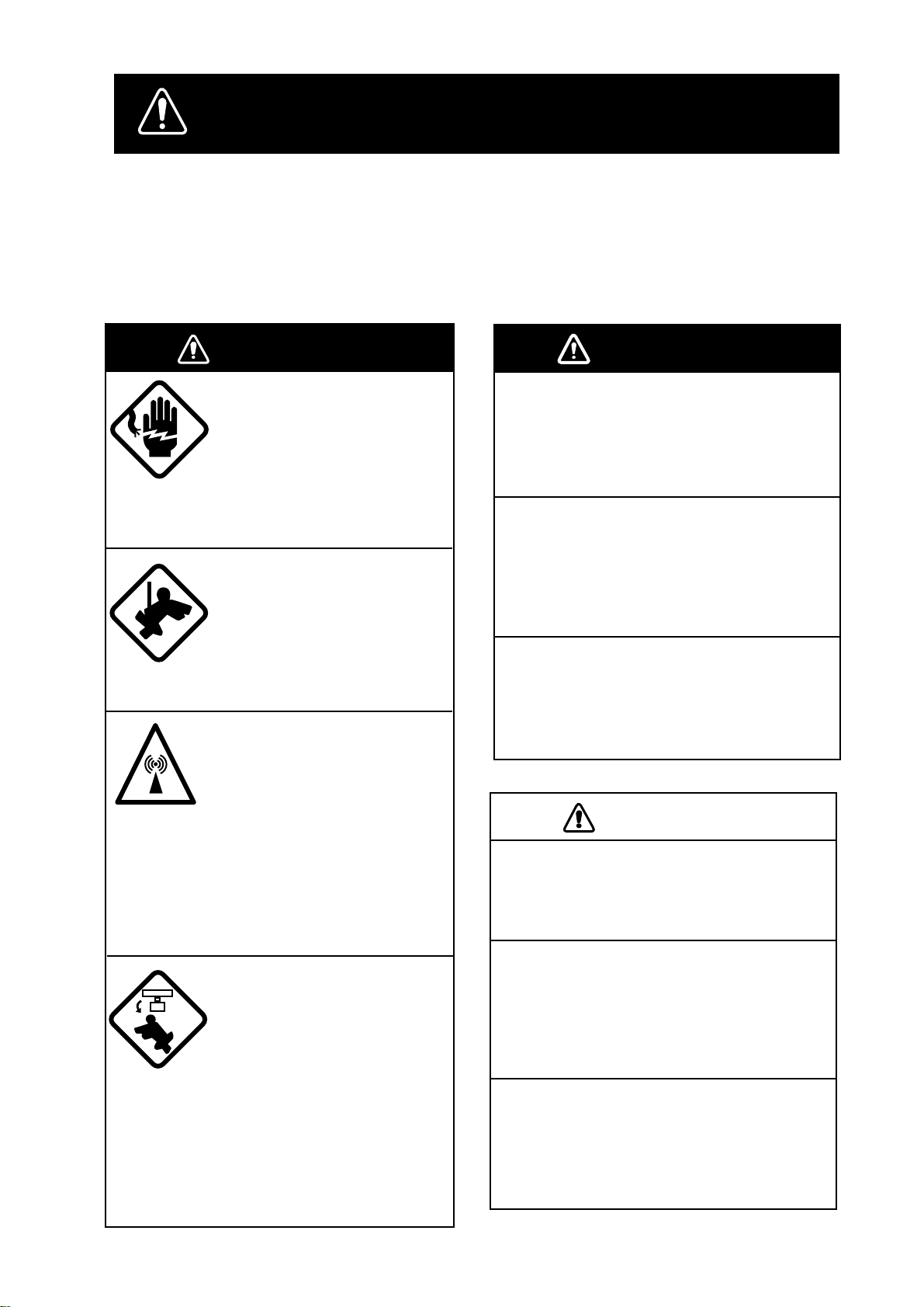
WARNING
Do not open the equipment.
Hazardous voltage which can
cause electrical shock, burn or
serious injury exists inside the
equipment. Only qualified
personnel should work inside
the equipment.
Wear a safety belt and hard
hat when working on the
antenna unit.
Serious injury or death can
result if someone falls from
the radar antenna mast.
Stay away from transmitting
antenna.
The radar antenna emits microwave radiation which can
be harmful to the human body,
particularly the eyes. Never
look directly into the antenna
radiator from a distance of
less than 1 m when the radar
is in operation.
WARNING
Do not disassemble or modify the
equipment.
Fire electrical shock or serious injury can
result.
Turn off the power immediately if water
leaks into the equipment or the
equipment is emitting smoke or fire.
Continued use of the equipment can cause
fire or electrical shock.
Do not place liquid-filled containers on
the top of the equipment.
Fire or electrical shock can result if a liquid
spills into the equipment.
Turn off the radar power
switch before servicing the
antenna unit. Post a warning sign near the switch
indicating it should not be
turned on while the antenna
unit is being serviced.
Prevent the potential risk of
someone begin struck by the
rotating antenna and exposure to RF radiation hazard.
iiiiiiiiiiiii
i
Page 4

FOREWORD
Congratulations on your choice of the
FURUNO MODEL 1832/1932/1942 Marine
Radar. We are confident you will see why the
FURUNO name has become synonymous with
quality and reliability.
For over 50 years FURUNO Electric Company
has enjoyed an enviable reputation for innovative and dependable marine electronics equipment. This dedication to excellence is furthered
by our extensive global network of agents and
dealers.
Y our radar is designed and constructed to meet
the rigorous demands of the marine environment. However, no machine can perform its
intended function unless properly installed and
maintained. Please carefully read and follow
the recommended procedures for installation,
operation and maintenance.
While this unit can be installed by the purchaser,
any purchaser who has doubts about his or her
technical abilities may wish to have the unit
installed by a FURUNO representative or other
qualified technician. The importance of a
through installation can not be overemphasized.
W e would appreciate hearing from you, the enduser, about whether we are achieving our purposes.
Thank you for considering and purchasing
FURUNO equipment.
Features
Your radar has a large variety of functions, all
contained in a remarkably small cabinet.
The main features of the MODEL 1832/1932/
1942 are:
¡ Traditional FURUNO reliability and qual-
ity in a compact, lightweight and low-cost
radar.
¡ Durable brushless antenna motor.
¡ On-screen alphanumeric readout of all op-
erational information.
¡ Standard features include EBL (Electronic
Bearing Line), VRM (Variable Range
Marker), Guard Alarm, Display Off Center,
and Echo Trail.
¡ W atchman feature periodically transmits the
radar to check for radar targets which may
be entering the alarm zone.
¡ Ship’s position in latitude and longitude and
Loran C Time Differences, range and bearing to a waypoint, and ship’s speed/ heading/course can be shown in the bottom text
area. (Requires a navigation aid which can
output such data in IEC 1162 format.)
¡ Zoom feature provided.
iii
Page 5

TABLE OF CONTENTS
FOREWORD...................................iii
SPECIFICATIONS ...........................v
EQUIPMENT LIST ........................viii
CONFIGURATION OF
MODEL 1832/1932/1942 .............x
1. PRINCIPLE OF OPERATION ......1
1.1 What is Radar?.................................... 1
1.2 How Ships Determined Position Before
Radar ..................................................1
1.3 How Radar Determines Range ........... 1
1.4 How Radar Determines Bearing.........1
1.5 Radar Wave Speed and Antenna Rota-
tion Speed...........................................1
1.6 The Radar Display ..............................1
2. BASIC OPERATION ....................3
2.1 Control Description ............................ 3
2.2 Display Indications and Markers ........ 4
2.3 Turning the Radar On and Off ............5
2.4 Transmitting........................................5
2.5 Stand-by..............................................5
2.6 Selecting the Range ............................ 6
2.7 Adjusting Picture Brilliance................6
2.8 Adjusting Receiver Sensitivity ...........6
2.9 Adjusting the A/C SEA Control (reduc-
ing sea clutter) .................................... 6
2.10 Adjusting the A/C RAIN Control
(reducing rain clutter).........................7
2.11 Erasing the Heading Line, North Mark
..........................................................8
2.12 Measuring the Range ........................8
2.13 Measuring the Bearing...................... 9
2.14 Using the Offset EBL ....................... 9
2.15 Shifting (off centering) the Picture . 10
2.16 Zoom............................................... 11
3. MENU OPERATION...................12
3.1 Basic Menu Operation ......................12
3.2 Selecting the Presentation Mode ...... 12
3.3 Magnifying Long Range Echoes (echo
stretch).............................................. 13
3.4 Echo Trail.......................................... 13
3.5 Suppressing Radar Interference ........ 14
3.6 Selecting Pulsewidth......................... 15
3.7 Guard Alarm .....................................15
3.8 Watchman ......................................... 16
3.9 Displaying Navigation Data ............. 17
3.10 OTHER MENU Description........... 18
3.11 Function Keys................................. 19
3.12 Suppressing Noise .......................... 19
3.13 Adjusting Brilliance of Markers .....19
3.14 Outputting Target Position.............. 19
4. FALS ECHOES ..........................20
4.1 Multiple Echoes ................................ 20
4.2 Side-lobe Echoes .............................. 20
4.3 Indirect Echoes ................................. 20
4.4 Blind and Shadow Sectors ................ 21
5. MAINTENANCE & TROUBLE-
SHOOTING ................................22
5.1 Preventitive Maintenance ................. 22
5.2 Replacing the Fuse............................ 22
5.3 Troubleshooting................................ 23
5.4 Self Test ............................................ 24
5.5 Life Expectancy of Magnetron .........24
6. INSTALLATION .........................25
6.1 Antenna Unit Installation.................. 25
6.2 Display Unit Installation...................30
6.3 Exchange of Fuse for 24/32V Power
Supply .............................................. 32
6.4 Checking the Installation ..................32
6.5 Adjustments ...................................... 32
iv
MENU TREE ............................. AP-1
ARP-10 (OPTION) .................... AP-2
Declaration of Conformity
Page 6

MODEL 1832
SPECIFICATIONS
ANTENNA UNIT
1. Radiator: Printed array
2. Radiator length: 60 cm
3. Horizontal beamwidth: 3.9°
4. Vertical beamwidth: 20°
5. Sidelobe:
Within ± 20° of mainlobe; less than -18 dB
Outside ± 20° of mainlobe; less than -23 dB
6. Polarization: Horizontal
7. Antenna rotation speed: 24 rpm
8. Wind resistance:
Relative wind speed 100 knots (51.5 m/s)
TRANSCEIVER MODULE
(contained in radome)
1. Transmitting tube: MG5248, E3571 or
MAF1421B
2. Frequency:
9410 MHz ±30 MHz
3. Peak output power: 4 kW nominal
4. Pulselength & pulse repetition rate:
0.08 µs, 2100 Hz (0.125, 0.25, 0.5, 0.75, 1.5)
0.3 µs, 1200 Hz (1.5, 2, 3)
0.8 µs, 600Hz (3, 4, 6, 8, 12, 16, 24, 36)
5. Warmup time: 1:30
6. Modulator: FET switching
method
7. I.F.: 60 MHz
8. Tuning: 3Automatic or
manual
9. Receiver front end:
MIC (Microwave
IC)
10. Bandwidth:
Tx pulselength 0.3 µs and 0.08 µs: 25 MHz
Tx pulselength 0.8 µs: 3 MHz
11. Duplexer: Circulator with diode
limiter
DISPLAY UNIT
monochrome CRT
3. Range scale (nm):
Range, Range interval and no. of Rings:
0.125 (0.0625, 2), 0.25 (0.125, 4), 0.75
(0.25, 3), 1 (0.25, 4), 1.5 (0.5, 3), 2 (0.5, 4),
3 (1, 3), 4 (1, 4), 6 (2, 3), 8 (2, 4), 12 (3, 4),
16 (4, 4), 24 (6, 4), 36 (12, 3)
4. Bearing resolution: 4°
5. Bearing accuracy: Within 1°
6. Range discrimination: Better than 20 m
7. Range ring accuracy:
0.9 % or range in use or 8 m, whichever is
larger
8. Minimum range: Better than 25 m
9. Markers:
Heading line, Bearing scale, Range ring,
VRM 1/2, EBL 1/2, Tuning indicator,
Cursor, Alarm zone, North mark (heading
sensor input required)
10. Alphanumeric indication:
Range, Range ring interval, Pulselength (SP,
MP, LP), Display mode (HU, CU, NU, TM),
Interference rejection (IR1, IR2, IR3), VRM
(1,2), EBL (1, 2), Automatic A/C SEA (A/C
AUTO), Stand-by (ST-BY), Radar alarm:
G(IN)/G(OUT)/G(ACKN), Echo stretch
(ES1, ES2), Range to cursor, Bearing to
cursor, Echo trailing (TRAIL), Trail time,
Trail elapsed time, Navigation data (navigation input required), heading (HDG, heading
sensor input required)
11. Vibration:
Vibration Total amplitude
5 to 12.5 Hz ± 1.6 mm
12 to 25 Hz ± 0.35 mm
25 to 50 Hz ± 0.10 mm
12. T emperature:
Antenna unit; -25 °C to + 70 °C
Display unit; -15 °C to + 55 °C
13. Humidity:
Relative humidity 93% or less at + 40°C
14. W aterproofing: Antenna unit;
IPX6
Display unit;
IPX5
15. Power supply & power consumption:
12 V, 24 V or 32 VDC (10.2 V to 41.6 VDC)
50W
16. Protection feature:
Protection against reverse polarity, overvoltage, overcurrent, and internal fault
17. Compass safe distance:
1. Indication system: PPI raster scan
2. Display: 10-inch rectangular
v
Page 7

MODEL 1932
MODEL 1942
SPECIFICATIONS
ANTENNA UNIT
1. Radiator: Slotted waveguide
array
2. Radiator length: 100 cm
3. Horizontal beamwidth: 3.9°
4. Vertical beamwidth: 27°
5. Sidelobe:
Within ± 20° of mainlobe; less than -24 dB
Outside ± 20° of mainlobe; less than -30 dB
6. Polarization: Horizontal
7. Antenna rotation speed: 24 rpm
8. Wind resistance:
Relative wind speed 100 knots (51.5 m/s)
TRANSCEIVER MODULE
(contained in antenna)
SPECIFICATIONS
ANTENNA UNIT
1. Radiator: Slotted waveguide
array
2. Radiator length: 120 cm
3. Horizontal beamwidth: 1.9°
4. Vertical beamwidth: 22°
5. Sidelobe:
Within ± 20° of mainlobe; less than -24 dB
Outside ± 20° of mainlobe; less than -30 dB
6. Polarization: Horizontal
7. Antenna rotation speed: 24 rpm
8. Wind resistance:
Relative wind speed 100 knots (51.5 m/s)
TRANSCEIVER MODULE
(contained in antenna)
1. Pulselength & pulse repetition rate:
0.08 µs, 2100 Hz (0.125, 0.25, 0.5, 0.75, 1.5)
0.3 µs, 1200 Hz (1.5, 2, 3)
0.8 µs, 600Hz (3, 4, 6, 8, 12, 16, 24, 36, 48)
2. Others: See MODEL 1832.
DISPLAY UNIT
1. Range scale (nm):
Range, Range interval and no. of Rings:
0.125 (0.0625, 2), 0.25 (0.125, 4), 0.75
(0.25, 3), 1 (0.25, 4), 1.5 (0.5, 3), 2 (0.5, 4),
3 (1, 3), 4 (1, 4), 6 (2, 3), 8 (2, 4), 12 (3, 4),
16 (4, 4), 24 (6, 4), 36 (12, 3), 48 (12, 4)
2. Compass safe distance:
Standard compass Steering compass
Display unit 0.75 m 0.6 m
Antenna unit 1.1 m 0.8 m
3. Others: See MODEL 1832.
1. Transmitting tube: MG5389 or E3560
2. Peak output power: 6 kW nominal
3. Pulselength & pulse repetition rate:
0.08 µs, 2100 Hz (0.125, 0.25, 0.5, 0.75, 1.5)
0.3 µs, 1200 Hz (1.5, 2, 3)
0.8 µs, 600Hz (3, 4, 6, 8, 12, 16, 24, 36, 48, 64)
4. Bandwidth:
Tx pulselength 0.3 µs and 0.08 µs: 25 MHz
Tx pulselength 0.8 µs: 5 MHz
5. Others: See MODEL 1832.
DISPLAY UNIT
1. Range scale (nm):
Range, Range interval and no. of Rings:
0.125 (0.0625, 2), 0.25 (0.125, 4), 0.75
(0.25, 3), 1 (0.25, 4), 1.5 (0.5, 3), 2 (0.5, 4),
3 (1, 3), 4 (1, 4), 6 (2, 3), 8 (2, 4), 12 (3, 4),
16 (4, 4), 24 (6, 4), 36 (12, 3), 48 (12, 4), 64
(16, 4)
2. Compass safe distance:
Standard compass Steering compass
Display unit 0.75 m 0.6 m
Antenna unit 1.0 m 0.74 m
vi
3. Power supply & power comsumption:
12 V, 24 V or 32 VDC (10.2 V to 41.6 VDC)
52W
Page 8

INTERFACE IEC 1162
ARPA FUNCTION
(NMEA0183)
(Input)
Own ship's position:
GGA>RMA>RMC>GLL
Speed:
RMA>RMC>VTG>VHW
Heading (True):
HDT>HDG*>HDM*>VHW>VHW*
Heading (Magnetic):
HDM>HDG*>HDT*>VHW>VHW*
Course (True): RMA>RMC>VTG
Course (Magnetic):
VTG>RMA*>RMC*
Waypoint (Range, Bearing): RMB>BWC>BWR
Loran time difference: RMA>GLC>GTD
Water depth: DPT>DBT
Water temperature: MDA>MTW
XTE: RMB>XTE>APB
*: Calculated value based Magnetic variation.
(Output)
TLL: On using "TLL" Key.
RSD: An interval of four seconds.
TTM: ARP-10 (Option)
(OPTION)
1. Internal Board ARP-10
2. Acquisition
Instant selection of auto or manual acquisi-
tion in 0.2 - 16 nm, relative speed 100kt.
3. Tracking
Automatic tracking of up to 10 acquired
targets betwen 0.1 to 16 nm.
4. Prediction of target motion
True or relative vectors, time scaled.
5. Past position
10 past positions of tracked targets.
6. Alarm Lost target. CPA/
TCPA
7. Automatic tracking range
0.1 - 16 nm
8. Target information (one target selected)
¡Distance and bearing from own ship to
target
¡Moving direction and speed
¡CPA (estimated Closest Point of Approach)
and TCPA (estimated Time to CPA)
9. Vector length 30 sec. - 30 min.
10. Plotting interval 15 sec. - 6 min.
vii
Page 9

EQUIPMENT LIST
Complete Set
MODEL 1832
emaNepyT.oNedoCytQskrameR
1tinUannetnA750-1700-BSR1
2
3
4seirasseccA00460-30PF278-680-000tes1
5
MODEL 1932/1942
1tinUannetnA
2
3
4
5straPerapS00221-30PS569-680-000tes1
tinUyalpsiD811-PDR
slairetaMnoitallatsnI
)enotceles(
straPerapS00221-30PS569-680-000
emaNepyT.oNedoCytQskrameR
tinUyalpsiD
slairetaMnoitallatsnI
)enotceles(
seirasseccA
00961-30PC348-680-000
01961-30PC448-680-000m51.yssaelbac.gis
02961-30PC548-680-000m02.yssaelbac.gis
03961-30PC648-680-000m03.yssaelbac.gis
A450-1600-BSR12391LEDOMroF
A550-2600-BSR12491LEDOMroF
811-PDR1
00071-30PC848-680-000
01071-30PC948-680-000m51.yssaelbac.gis
02071-30PC058-680-000m02.yssaelbac.gis
03071-30PC158-680-000m03.yssaelbac.gis
00460-30PF278-680-000tes1
1
tes1
tes1
tes1
m01.yssaelbac.gis
m01.yssaelbac.gis
Optional Equipment
emaNepyT.oNedoCytQskrameR
1draoBPRA01-PRA258-680-0001
reifitceR26-RP484-310-000
584-310-000CAV011,2381
2
3243-UR344-030-0001 CA,2491/2391
3sneLgniyfingaM0051-121-30000-934-8001
4tiKtnuoMhsulF541-30PO060-674-8001
5)1(tekcarBgnitnuoM29-30PO070-544-8001 2381LEDOMroF
6rezzuBlanretxE12-30PO790-030-0001.1etoneeS*
.yssAelbaC050-3000FPS6A-JM306-711-000
001-9000FPS6A-JM632-521-000
001-7000FPS6A-JM732-521-000
7
Note 1) Even though the display unit meets waterproof standard IPX-5, the connection of external buzzer, radar
plotter and/or remote display can affect waterproofness. Watertight integrity cannot be guaranteed. When these
modification has been done, the display unit should not be mounted where exposed.
Note 2) Conversion from MCP connector (square type) to MJ connector (circular type).
001-21000FPS6A-JM718-331-000
050-21000FPS6A-JM424-431-000
500-6000FPL42B-JM834-041-000.2etoneeS*
1
684-310-000CAV022,2381
784-310-000CAV032,2381
1
CAV001,2381
viii
Page 10

Installation Materials
CP03-169xx (Model 1832)
emaNepyT.oNedoCytQskrameR
1m01elbaClangiS001-2000FPL42B-JM279-831-000
m51elbaClangiS051-2000FPL42B-JM079-831-000
m02elbaClangiS002-2000FPL42B-JM479-831-000
m03elbaClangiS003-2000FPL42B-JM379-831-000
.enotceleS
.dettifrotcennoC
1
2
3daeHdettolS
4
5
6
CP03-170xx (Model 1932/1942)
1m01elbaClangiS001-2000FPL42B-JM279-831-000
2elbaCrewoP2339S30829-831-0001
3rehsaWlaeSXD3501WC120-058-0004
4tloBxeH403SUS06x21M191-268-0004
5tuNxeH403SUS21M211-368-0004
elbaCrewoP2339S30829-831-000
403SUS52x01M803-268-000
tloBxeH
rehsaWtalF403SUS01M131-468-000
rehsaWgnirpS403SUS01M162-468-000
erocCME215152SS40E376-441-000
emaNepyT.oNedoCytQskrameR
m51elbaClangiS051-2000FPL42B-JM079-831-000
m02elbaClangiS002-2000FPL42B-JM479-831-000
m03elbaClangiS003-2000FPL42B-JM379-831-000
tes1
4
4
4
1
1
.enotceleS
.dettifrotcennoC
6rehsaWtalF403SUS21M231-468-0004
7rehsaWgnirpS403SUS21M362-468-0004
8niPdettolSSUS54x01093-668-0002
Spare Parts (SP03-12200)
emaNepyT.oNedoCytQskrameR
1esuFV521CAA5A-OBGF460-945-0002
2esuFV521CAA01OBGF560-945-0002
3)A5(lebaL0-2151-921-30087-842-0011 CDV23/42roF
ylppus
Accessories (FP03-06400)
emaNepyT.oNedoCytQskrameR
1wercSgnippaT403SUS02x6480-208-0005
2bonK20460-30PF023-974-8002
3regnaH10460-30PF013-974-8001
4.yssAdooH01840-30PF004-144-8001
CDV23/42roF
ylppusrewop
rewopCDV21roF
ix
Page 11
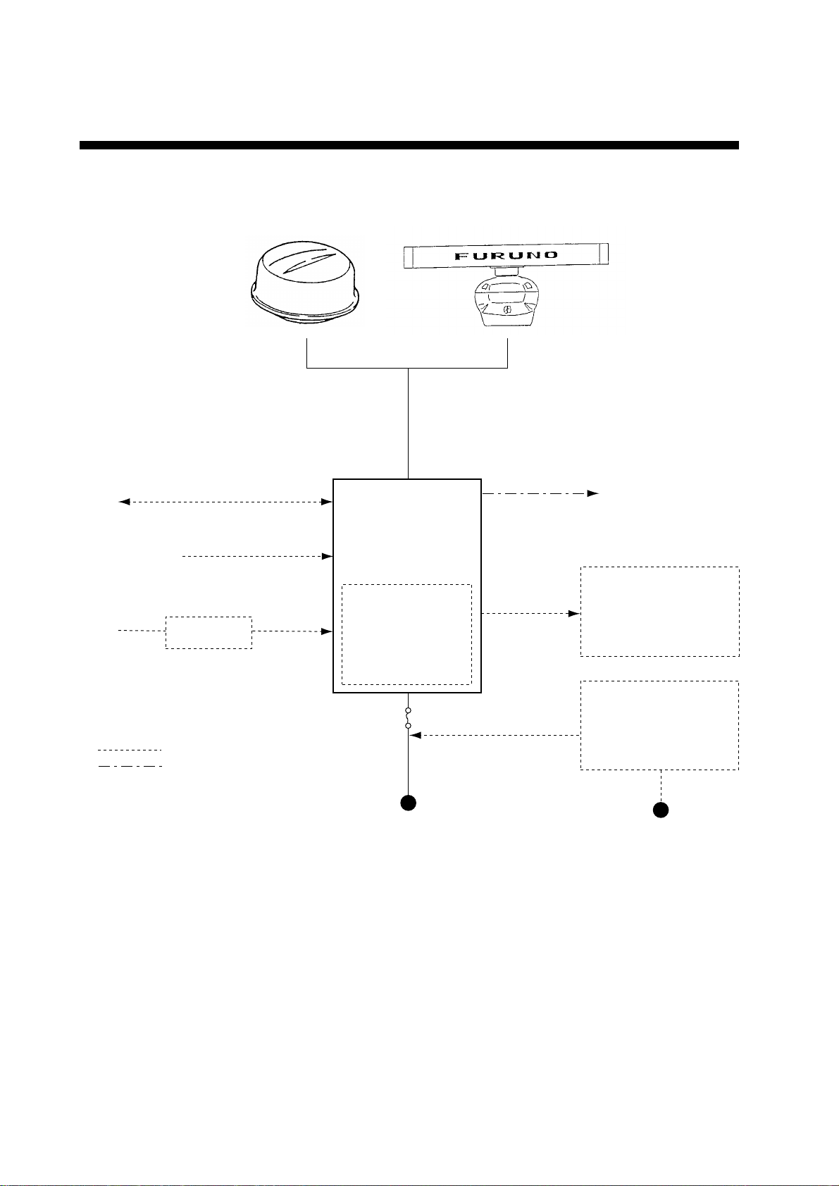
CONFIGURATION OF MODEL 1832/1932/1942
Antenna Unit
NAV
Video Sounder
Gyro
*Equivalent to NMEA 0183
IEC 1162* (In/Out)
IEC 1162* (In)
Gyro Converter
AD-100
: Option
: Local Supply
(1832)
Display Unit
RDP-118
Auto Plotter
ARP-10
12 VDC: 5A
24 VDC: 10A
(1932/1942)
Remote Display
FMD-811/1800
External Alarm
Buzzer OP03-21
Rectifier
PR-62(1832),
RU-3423(1932/1942)
12/24/32 VDC
Note: Even though the display unit meets waterproof standard IPX-5, the connection of external
buzzer , radar plotter and/or remote display can affect waterproofness. W atertight integrity cannot
be guaranteed. When these modification has been done, the display unit should not be mounted
where exposed.
115/230 VAC
x
Page 12

1. PRINCIPLE OF OPERATION
1.1 What is Radar?
The term “RADAR” is an acronym meaning
RAdio Detection And Ranging. Although the
basic principles of radar were developed during World War II, echoes as an aid to navigation is not a new development.
1.2 How Ships Determined Position Before Radar
Before the invention of radar, when running in
fog near a rugged shoreline, ships would sound
a short blast on their whistles, fire a shot, or
strike a bell. The time between the origination
of the sound and the returning of the echo indicated how far the ship was from the cliffs or the
shore. The direction from which the echo was
heard indicated the relative bearing of the shore.
1.3 How Radar Determines Range
Radar determines the distance to the target by
calculating the time difference between the
transmission of a radar signal and the reception
of the reflected echo. It is a known fact that radar waves travel at a nearly constant speed of
162,000 nautical miles per second. Therefore
the time required for a transmitted signal to
travel to the target and return as an echo to the
source is a measure of the distance to the target. Note that the echo makes a complete round
trip, but only half the time of travel is needed to
determine the one-way distance to the target.
This radar automatically takes this into account
in making the range calculation.
1.4 How Radar Determines Bearing
The bearing to a target found by the radar is
determined by the direction in which the radar
scanner antenna is pointing when it emits an
electronic pulse and then receives a returning
echo. Each time the scanner rotates pulses are
transmitted in the full 360 degree circle, each
pulse at a slightly different bearing from the
previous one. Therefore, if one knows the direction in which the signal is sent out, one knows
the direction from which the echo must return.
1.5 Radar Wave Speed and Antenna Rotation Speed
Note that the speed of the radar waves out to
the target and back again as echoes is extremely
fast compared to the speed of rotation of the
antenna. By the time radar echoes have returned
to the scanner, the amount of scanner rotation
after initial transmission of the radar pulse is
extremely small.
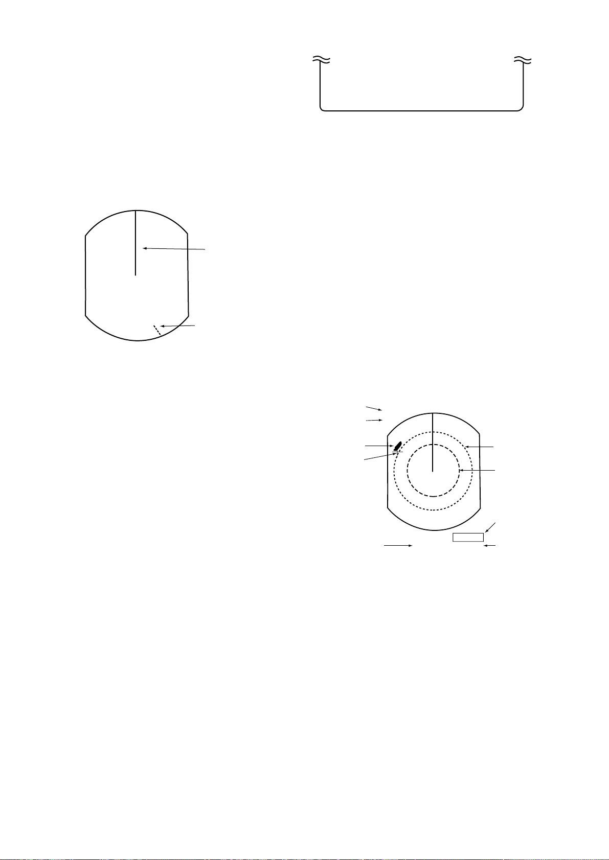
1.6 The Radar Display
The range and bearing of a target is displayed
on what is called a Plan Position Indicator (PPI).
This display is essentially a polar diagram, with
the transmitting ship’s position at the center.
Images of target echoes are received and displayed at their relative bearings, and at their
distance from the PPI center.
With a continuous display of the images of tar gets, the motion of the transmitting ship is also
displayed.
1
Page 13
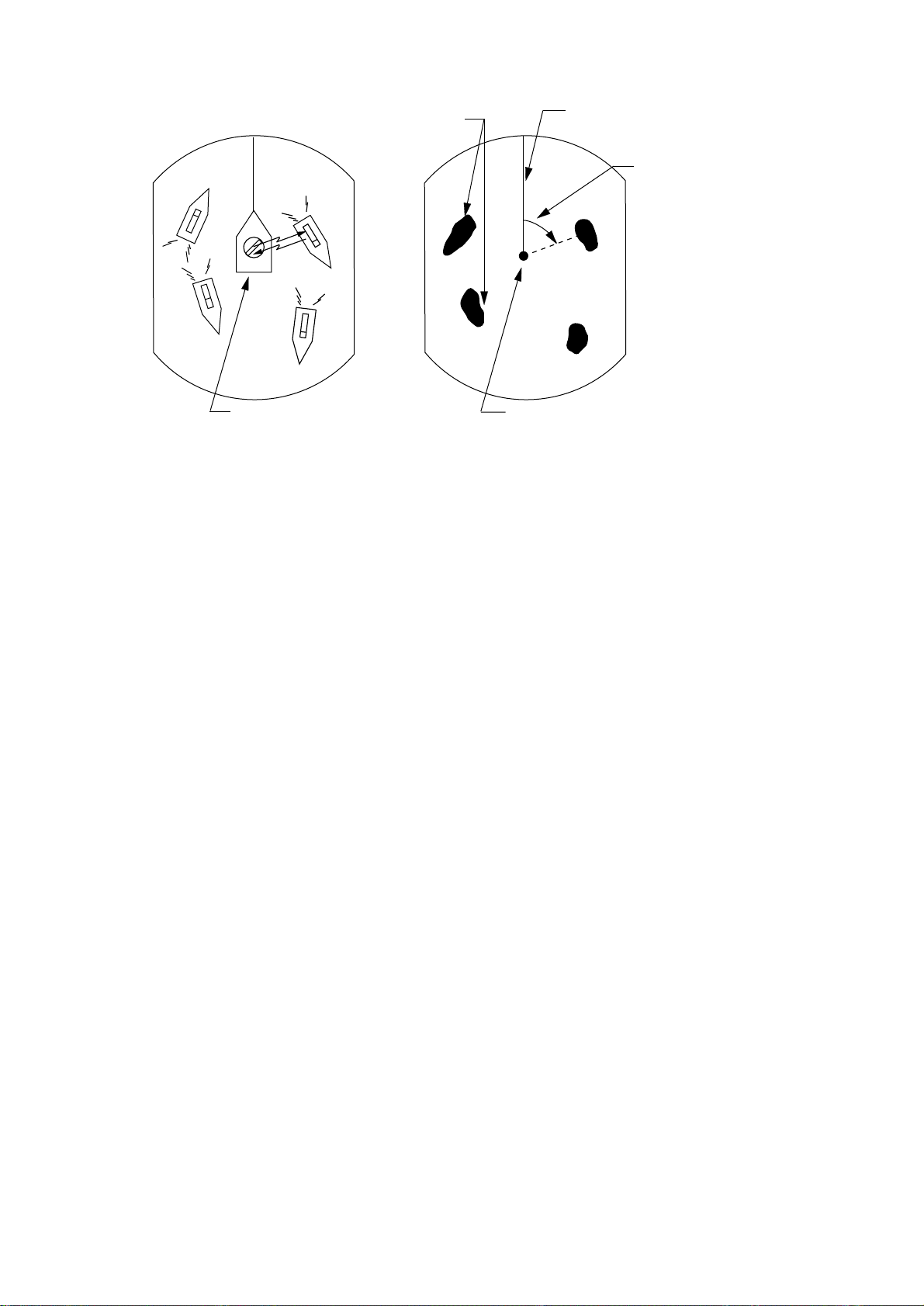
Targets
Heading line
Range and bearing
of a target, relative
to own ship, are
A
D
A
readable on the PPI.
D
B
C
Own ship
(radar)
(A) Bird's eye view of situation
B
C
Own ship
in center
(B) Radar picture of (A)
Figure 1-1 How radar works
2
Page 14
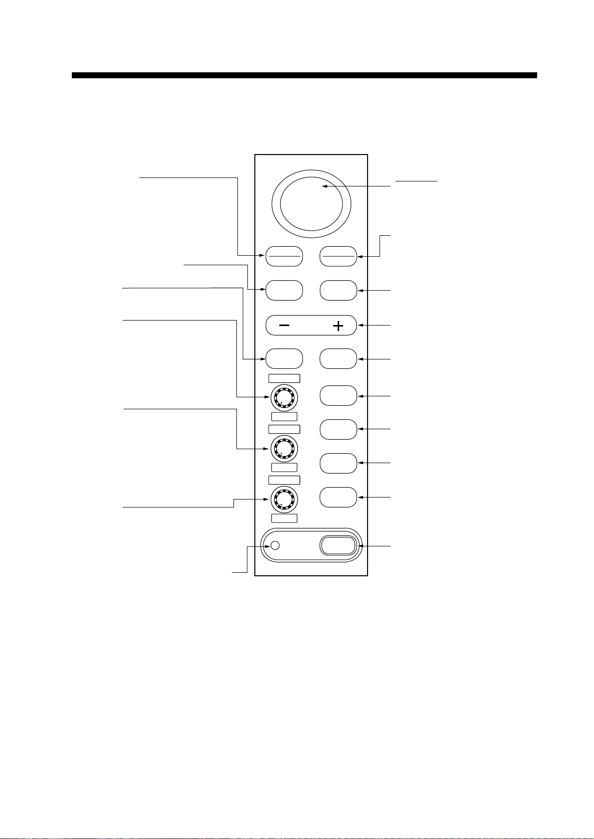
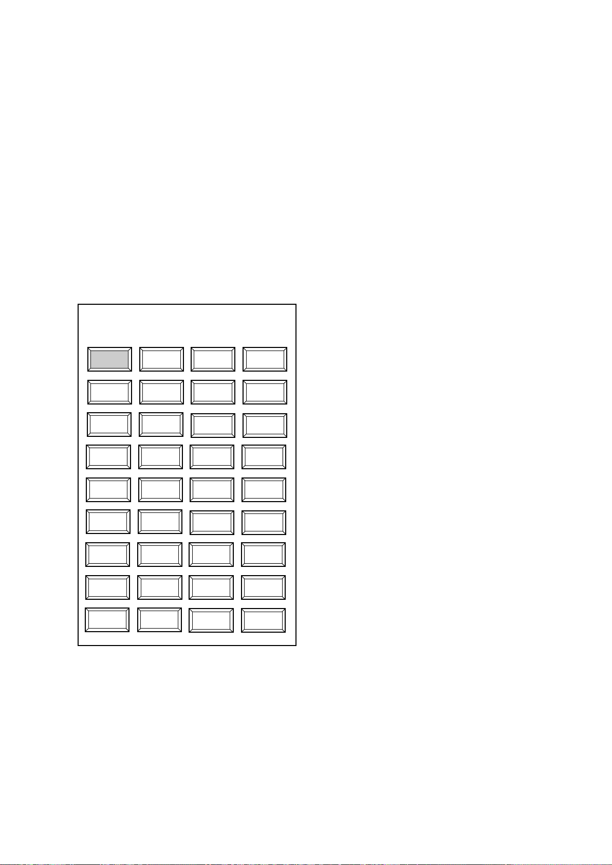
2.1 Control Description
2. BASIC OPERATION
Brief press:
Displays the data of target
selected with the cursor.
Long press:
Terminates plotting of the target
selected with the cursor.
Opens/closes menus.
Selects
EBL1/EBL2/VRM1/VRM2.
Control:
Adjusts sensitivity.
Switch:
Temporarily erases heading
line (and north mark if
displayed).
Control:
Reduces sea clutter.
Switch*:
(Long press) Shifts your vessel’s
position to cursor location.
(Brief press) Doubles size of
area between your vessel and
location selected by cursor.
Control:
Reduces rain clutter.
Switch*:
Displaces the EBL origin.
SELECT
CANCEL
MENU
RANGE
EBL/VRM
SELECT
GAIN
HM-OFF
A/C SEA
F1
A/C RAIN
F2
ACQ
ENTER
GUARD
EBL/VRM
CONTROL
TLL
A/C AUTO
BRILL
ST BY
TX
POWER
Omnipad
Shifts cursor, VRM and EBL;
select items and options on
menu.
(1) Acquires the target selected
with the ominipad.
(2) Registers selection on
menus.
Sets guard zone area.
Selects radar range.
Enables/erases
EBL1/EBL2/EBL3/EBL4.
Outputs target position data.
Automatically reduces sea and
rain clutters.
Adjusts display brilliance.
Sets radar in stand-by;
transmits radar pulse.
Turns power on/off.
Lights when the economy mode
is on.
*Default switch function.
Figure 2-1 Control panel
3
Page 15
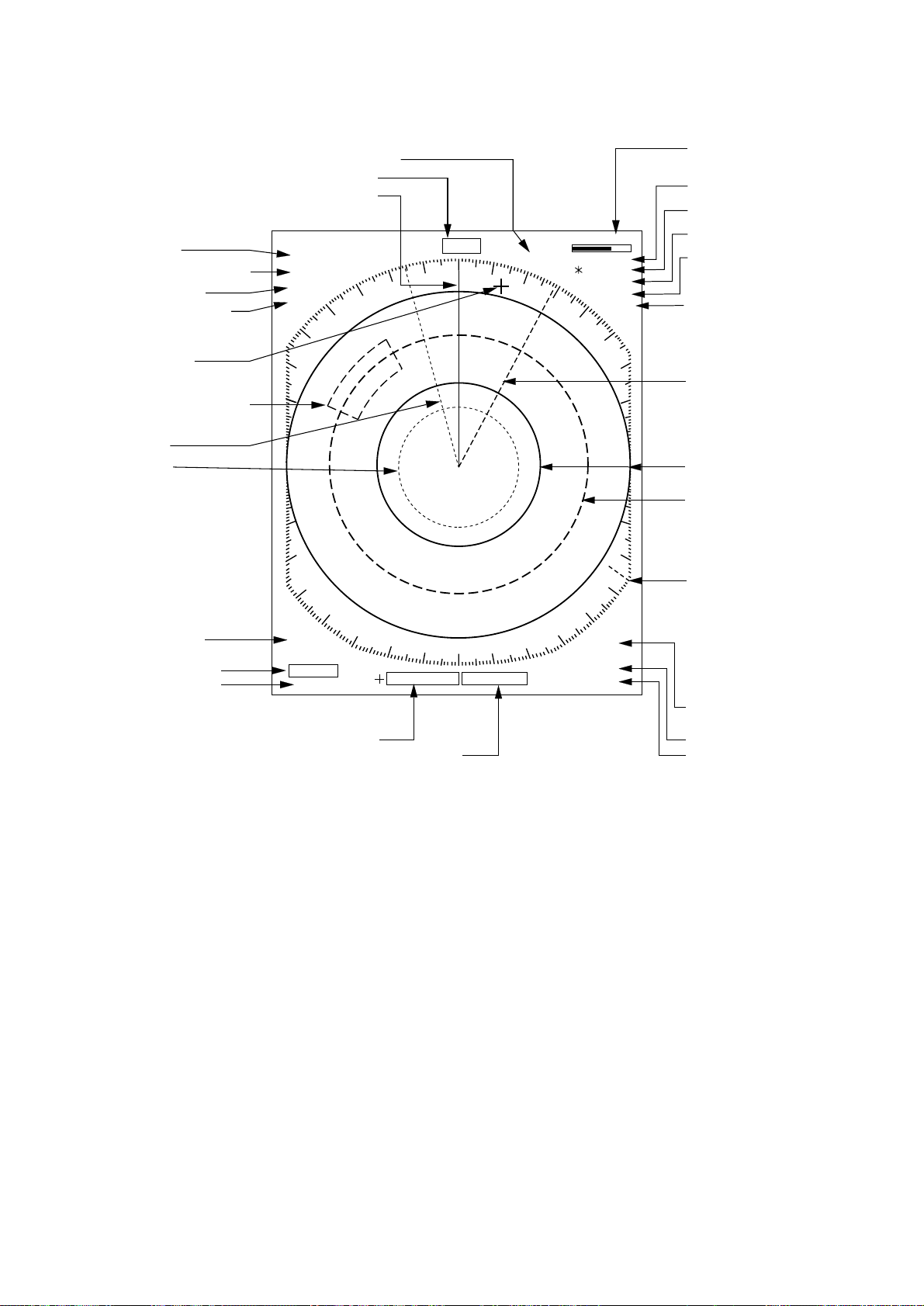
2.2 Display Indication and Markers
Heading (requires heading data)
Range (P.6)
Range ring interval (P.6)
Pulselength (P.6)
Display mode (P.12)
Cursor (P.8, 9)
Guard zone area (P.15)
EBL1 (P.9)
VRM1 (P.8)
Echo trail elapsed time (P.13)
Heading line (P.8)
. 125NM
.
0625
SP
HU
HDG 234.5°
TRAIL
25 : 38
AUTO
30M
G (OUT)
ZOOM
ES1
OFFCENTER
Tuning indicator (P.6)
Echo trail time (P.13)
Guard Zone (P.15)
Zoom (P.11)
Echo Stretch (P.13)
Off center (P.10)
EBL2 (P.9)
Range ring (P.8)
VRM2 (P.8)
North mark (P.8)
A/C AUTO (P.7)
EBL1 bearing (P.9)
EBL2 bearing (P.9)
A/C
AUTO
EBL
345.6 R
°
23.0 R
°
Cursor bearing (P.9)
Cursor range (P.8)
Figure 2-2 Display indications
13.5 R°
0.142NM
IR2
VRM
0.048NM
0.100NM
Interference rejector (P.14)
VRM1 range (P.8)
VRM2 range (P.8)
4
Page 16
2.3 Turning the Radar On/Off
2.5 Stand-by
Press the [POWER] key to turn the radar on or
off.
The control panel lights and a timer displays
the time remaining for warm up of the magnetron (the device which produces radar pulses),
counting down from 1:30 to 0:01.
2.4 Transmitting
After the power is turned on and the magnetron
has warmed up, STBY (Stand-By) appears at
the screen center. This means the radar is now
fully operational. In stand-by the radar is available for use at anytime - but no radar waves are
being transmitted.
Press the [STBY TX] key to transmit.
When transmitting, any echoes from targets
appear on the display. This radar displays echoes in eight tones of green according to echo
strength.
When you won’t be using the radar for an extended period, but you want to keep it in a state
of readiness, place it in stand-by by pressing
the [STBY TX] key. The display shows
“STBY,” navigation data, or goes into the
economy mode depending on menu setting.
(More on menu operation later.)
Economy mode
The CR T can be set to automatically turn itself
off when in stand-by , to reduce power consumption. This feature is called the “economy mode.”
Power consumption in the economy mode is 28
W. When the economy mode is on, the lamp
next to the [POWER] key lights.
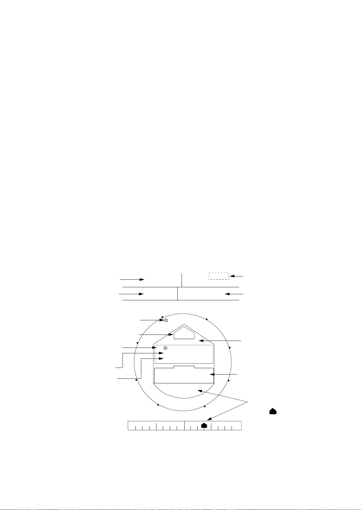
Navigation data display during
stand-by
If a navigation aid inputs navigation data to this
radar, navigation data can be displayed during
stand-by. You can turn the navigation data display on/off through the menu. Figure 2-3 shows
a typical navigation data display during standby.
Speed
Depth
To Waypoint
bearing Heading
Time-to-go to
TO Waypoint
Bearing TO Waypoint
Range to TO Waypoint
SPEED
10.5
kt
DEPTH TEMPERATURE
Heading
N
L
1.0
XTE
125
0.5
m
WPT TTG 01:08
BRG
RNG
LAT 30°00.00N
LON 135°00.00E
E
HDG
092.5°
CRS 180.0°M
45.0° M
12.0NM
OWN SHIP
TD 36378.1
59096.4
XTE
R 0.3NM
W
TRIP
000.3 nm
+17.3
0.5
ST-BY
°C
Time-to-go to Stand-by
Trip distance since power on
Course
S
Ship's position in
latitude and longitude
and Loran TDs
Cross Track Error
XTE
Mark " " shows
R
direction and amount
of error.
1.0
Figure 2-3 Typical navigation data display
during stand-by
5
Page 17

Note 1: Availability of a particular display item
depends on incoming data.
2.8 Adjusting Receiver Sensitivity
Note 2: When Range to Waypoint reaches 0.1
nm, the WPT mark jumps to dead
ahead even though a difference may
exist between heading and BRG to
WPT.
Note 3: When cross track error exceeds 1 nm
on either side, the XTE mark starts
blinking.
2.6 Selecting the Range
The range selected automatically determines the
range ring interval, the number of range rings,
pulselength and pulse repetition rate, for optimal detection capability in short to long ranges.
You can select which ranges and pulselength
(for 1.5 and 3 mile ranges) to use through the
menu. The range, range ring interval and
pulselength appear at the top left-hand corner
of the display.
To select a range;
Press the [- RANGE +] key . The range and range
ring interval appear at the top left corner on the
display.
Tips for selecting the range
¡ When navigating in or around crowded har-
bors, select a short range to watch for possible collision situations.
¡ If you select a lower range while on open
water, increase the range occasionally to
watch for vessels that may be heading your
way.
The [GAIN] control adjusts the sensitivity of
the receiver. It works in precisely the same
manner as the volume control of a broadcast
receiver, amplifying the signals received.
The proper setting is such that the background
noise is just visible on the screen. If you set up
for too little sensitivity, weak echoes may be
missed. On the other hand excessive sensitivity
yields too much background noise; strong targets may be missed because of the poor contrast between desired echoes and the
background noise on the display.
To adjust receiver sensitivity, transmit on long
range, and adjust the [GAIN] control so background noise is just visible on the screen.
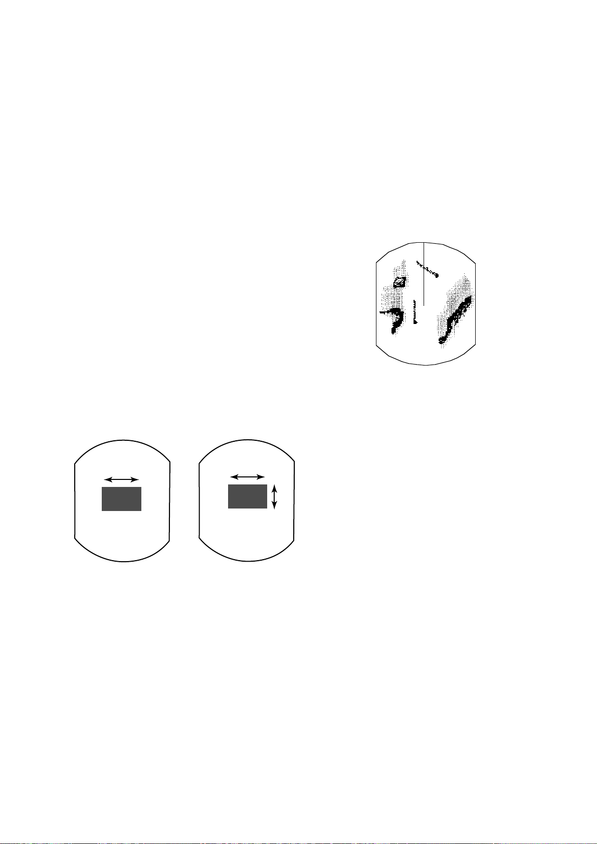
2.9 Adjusting the A/C SEA Control (reducing sea clutter)
Echoes from waves can be troublesome, covering the central part of the display with random
signals known as “sea clutter.” The higher the
waves, and the higher the scanner above the
water, the further the clutter will extend. Sea
clutter appears on the display as many small
echoes which might affect radar performance.
(See the left-hand figure in Figure 2-4.) When
sea clutter masks the picture, adjust the A/C SEA
control to reduce the clutter.
How the A/C SEA control works
The [A/C SEA] control reduces the amplification of echoes at short ranges (where clutter is
the greatest) and progressively increases amplification as the range increases, so amplification will be normal at those ranges where there
is no sea clutter.
2.7 Adjusting Picture Brilliance
The [BRILL] key adjusts the brilliance of the
radar picture in sixteen levels.
Press the [BRILL] key to set the brilliance level.
The current level momentarily appears on the
screen.
6
Page 18
Adjusting the A/C SEA control
The proper setting of the A/C SEA should be
such that the clutter is broken up into small dots,
and small targets become distinguishable.
If the control is set too low , tar gets will be hidden in the clutter, while if it is set too high, both
sea clutter and targets will disappear from the
display. In most cases adjust the control until
clutter has disappeared to leeward, but a little
is still visible windward.
2.10 Adjusting the A/C RAIN Control (reducing rain clutter)
The vertical beamwidth of the antenna is designed to see surface targets even when the ship
is rolling. However, by this design the unit will
also detect rain clutter (rain, snow , hail, etc.) in
the same manner as normal targets. Figure 2-5
shows the appearance of rain clutter on the display.
1. Confirm that the sensitivity is properly adjusted, and then transmit on short range.
2. Adjust the [A/C SEA] control so small targets are distinguishable but some clutter remains on the display.
Sea clutter at
display center
A/C SEA control adjusted;
sea clutter suppressed.
Figure 2-4 How to adjust the A/C SEA control
Tip for adjusting the A/C SEA
Adjusting A/C RAIN
When rain clutter masks echoes, adjust the [A/
C RAIN] control. This control splits up these
unwanted echoes into a speckled pattern, making recognition of solid targets easier.
Appearance of
rain clutter
A/C RAIN control adjusted;
rain clutter suppressed.
Figure 2-5 Effect of A/C RAIN
A common mistake is to over -adjust the circuit
so all the clutter is removed. As an example set
up for maximum A/C SEA. You will see how
the center of the display becomes dark. This
dark zone can be dangerous (targets may be
missed), especially if the sensitivity is not properly adjusted. Always leave a little clutter visible on the display to be sure weak echoes will
not be suppressed. If there is no clutter visible
on the display, turn off the circuit.
Note: In addition to reducing clutter, the [A/C
RAIN] control can be used in fine weather
to clarify the picture when navigating in
confined waters. However, with the circuit activated the receiver is less sensitive. Therefore, turn off the circuit when
its function is not required.
Automatic adjustments of A/C SEA
and A/C RAIN
Push the [A/C AUTO] key. “A/C AUTO” appears at the bottom left-hand corner of the display when the A/C AUT O circuit is on. You can
fine tune by adjusting the [A/C SEA], [A/C
RAIN] and [GAIN] controls.
7
Page 19
2.11 Erasing the Heading Line, North Mark
The heading line or north mark (available with
gyrocompass connection) may occasionally
mask a target. To view the target, you can temporarily erase the heading line and north mark
by pressing and holding down the [GAIN (HM
OFF)] control. Release the control to re-display
the marks.
Heading
line
North mark
Figure 2-6 Heading line and north mark
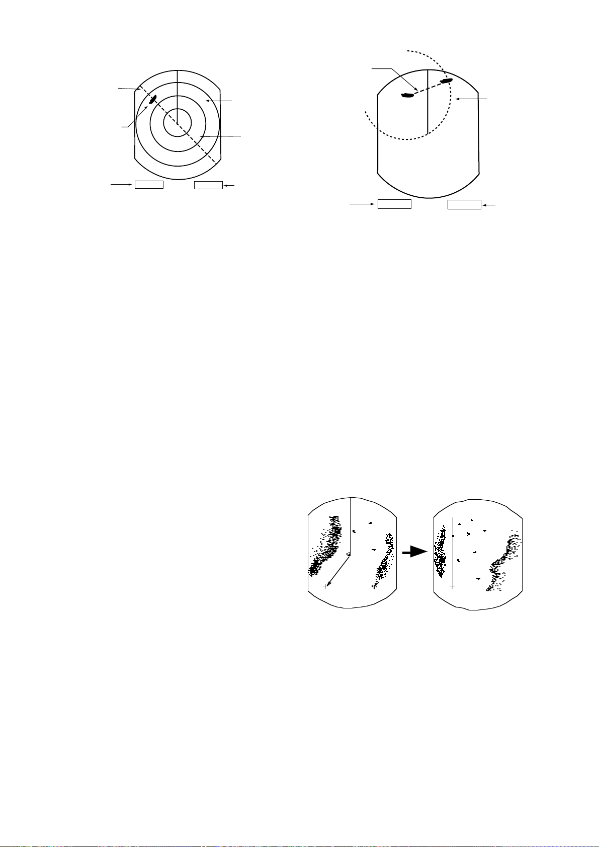
2.12 Measuring the Range
You can measure the range to a target three
ways: by the range rings, by the cursor, and by
the VRM (Variable Range Marker).
By range ring
EBL
345.6°R
23.0°R
VRM
5.3°NM
12.5°NM
Figure 2-7 Display bottom, showing location
of EBL and VRM readouts
2. Press the [EBL/VRM CONTROL] key to
enable control of the VRM by the omnipad.
3. Operate the omnipad to place the outside
edge of the VRM on the inside edge of the
target.
4. Check the VRM readout at the bottom righthand corner of the display to find the range
to the target.
5. To anchor the VRM, press the [EBL/VRM
CONTROL] key.
To erase the VRM, press and hold down the
[EBL/VRM CONTROL] key about two seconds.
Range
Range ring
interval
Target
Cursor
6.0 NM
2.0
VRM1
VRM2
Count the number of rings between the center
of the display and the target. Check the range
ring interval and judge the distance of the echo
from the inner edge of the nearest ring.
By cursor
Operate the omnipad to place the cursor intersection on the inside edge of the target echo,
The range to the target, as well as the bearing,
appears at the bottom of the display.
By VRM
1. Press the [EBL/VRM SELECT] key to circumscribe a VRM readout (at the bottom
right-hand corner). Each press of the key
selects the readout of EBL1, EBL2, VRM1
or VRM2 in that order.
VRM1
range
VRM2
range
Cursor range
4.0 NM
VRM
4.0 NM
3.0 NM
Figure 2-8 Measuring range by the cursor,
range rings and VRM
Note: Y ou can display the range readout of the
VRM and cursor in nautical miles, statute miles
or kilometers. For details see the next chapter.
8
Page 20

2.13 Measuring the Bearing
There are two ways to measure the bearing to a
target: by the cursor, and by the EBL (Electronic
Bearing Line).
By cursor
Operate the omnipad to bisect the target with
the cursor intersection. The bearing to the target appears at the bottom of the display.
By EBL
1. Press the [EBL/VRM SELECT] key to cir-
cumscribe an EBL readout (at the bottom
left-hand corner). Each press of the key selects the readout of EBL1, EBL2, VRM1 or
VRM2 in that order.
2. Press the [EBL/VRM CONTROL] key to
enable control of the omnipad.
Note: The bearing readout for the EBL and the
cursor can be displayed in relative or true
bearing (true bearing requires heading
sensor input). For north up and course
up display modes the bearing reference
is always true. For details see the next
chapter.
Tips for measuring bearing
¡ Bearing measurements of smaller targets are
more accurate; the center of larger target pips
is not as easily identified.
¡ Bearings of stationary or slower moving tar-
gets are more accurate than bearings of faster
moving targets.
¡ To minimize bearing errors keep echoes in
the outer half of the picture by changing the
range scale; angular difference becomes difficult to resolve as a target approaches the
center of the display.
3. Operate the omnipad to bisect the target with
the EBL.
4. Check the EBL readout at the bottom left-
hand corner of the display to find the bearing to the target.
5. To anchor the EBL, press the [EBL/VRM
CONTROL] key.
T o erase the EBL and its readout, press and hold
down the [EBL/VRM CONTROL] key about
two seconds.
6.0 NM
EBL1 bearing
EBL1 bearing
2.0
EBL
40.0° R
135.0° R
40.0°R 4.0 NM
Target
Cursor
EBL1
EBL2
Cursor
Bearing
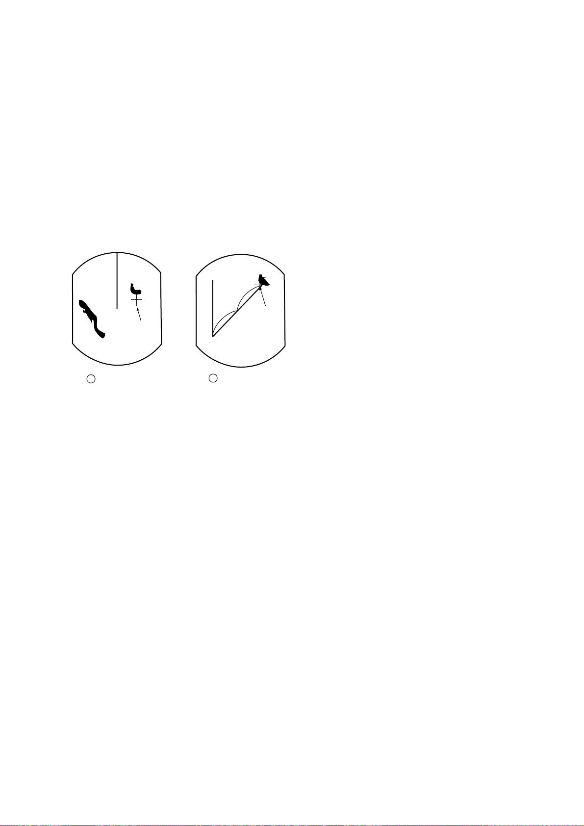
2.14 Using the Offset EBL
The offset EBL provides two functions: predict
collision course of radar target and measure the
range and the bearing between two targets.
Predicting collision course
1. Press the omnipad to place the cursor on the
center of the target.
2. Press the [EBL/VRM SELECT] key to
choose EBL1 readout and then press the
[EBL/VRM CONTROL] key.
3. Select EBL OFFSET on the menu and press
the [ACQ/ENTER] key.
4. Press the [EBL/VRM CONTROL] key.
5. Operate EBL1 so it passes through the center of the target.
If the target tracks along the EBL towards the
center of the display (your vessel’s position),
the target may be on a collision course.
To cancel, select EBL OFFSET and press the
[ACQ/ENTER] key.
Figure 2-9 How to measure bearing by EBL
and cursor
9
Page 21
EBL1 origin
(initial position
of target)
6.0 NM
2.0
VRM1
EBL1
B
A
VRM1
Target moved
here.
EBL1
bearing
EBL
70.0° R
VRM
6.0 NM
Offset EBL
(EBL1)
VRM1
range
Figure 2-10 Predicting collision course by
using the offset EBL
Measuring range and bearing between
two targets
The procedure which follows shows how to
measure the range and bearing between target
“A” and target “B” in Figure 2-11.
1. Press the omnipad to place EBL1’s origin
(cursor) on the center of target “A”.
2. Press the [EBL/VRM SELECT] key to
choose EBL1 readout and then press the
[EBL/VRM CONTROL] key.
3. Select EBL OFFSET on the menu and press
the [ACQ/ENTER] key . EBL1’s origin shifts
to cursor .
4. Press the [EBL/VRM CONTROL] key.
EBL1
bearing
70.0° R
VRM
4.5 NM
VRM1
range
Figure 2-11 Measuring the range and bearing
between two targets by using the offset EBL
2.15 Shifting (off centering) the Picture
Y our vessel’ s position can be shifted up to 75%
of the range in use to view the situation around
your vessel without changing the range or size
of targets.
1. Press the omnipad to set cursor where de-
sired.
2. Press the [F1 (A/C SEA)] control if its func-
tion is set for SHIFT (default setting), or select SHIFT on the menu. OFFCENTER
appears at the top right corner of the display
when the picture is shifted.
5. Press the omnipad to bisect target “B” with
EBL1. Check the EBL1 readout to find the
bearing between target “A” and target “B”.
6. Press the [EBL/VRM SELECT] key to
choose VRM1 readout. Press the omnipad
to place the outside edge of VRM1 on the
inside edge of target “B.” Check the VRM1
readout to find the range between target “A”
and target “B”.
7. T o cancel, select EBL OFFSET on the menu
and press the [ACQ/ENTER] key.
Cursor Cursor
1 Place cursor
where desired.
2 Press SHIFT ZOOM
key to off center display.
Figure 2-12 Shifting the picture
Cancelling shifted picture
Press the [F1 (A/C SEA)] control again.
10
Page 22
2.16 Zoom
The zoom feature allows you to double the size
of the area between your vessel and any location within the current range to take a closer
look at an area of interest.
1. Select location with the cursor.
2. Press and hold down the [F1 (A/C SEA)]
control about two seconds if its function is
set for ZOOM (default setting), or select
ZOOM on the menu. Zoom appears at the
top right corner when the ZOOM function is
on.
Cursor
Cursor
1
Place cursor
where desired.
2
Press [F1] to zoom.
Figure 2-13 Zoom function
Note 1: Zoom is cancelled when range or pre-
sentation mode is changed.
Cancelling zoom
Press the [F1 (A/C SEA)] control again.
11
Page 23
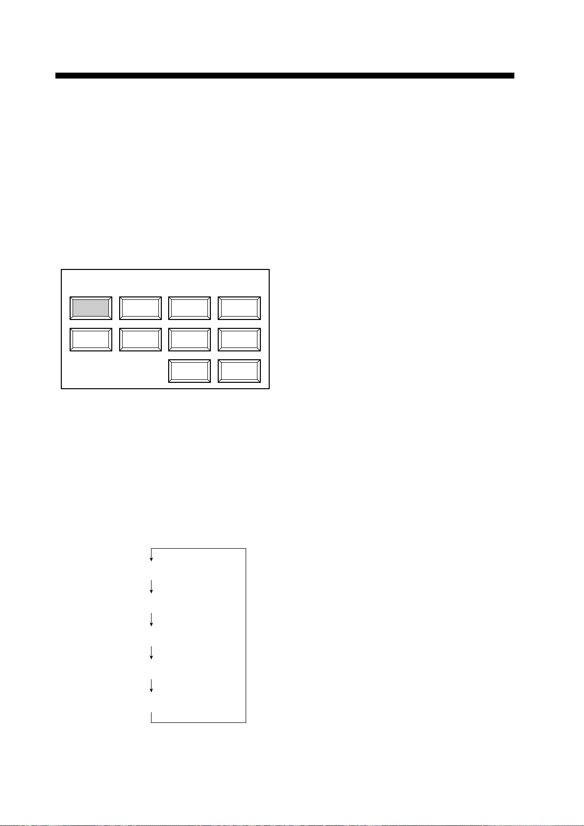
3. MENU OPERATION
3.1 Basic Menu Operation
The menu mostly contains less-often used
functions which once preset do not require
regular adjustment. T o open or close the menu,
press the [MENU] key. You can select items
on the menu with the omnipad. The complete
menu appears on page AP-1.
1. Press the [MENU] key to display the main
menu.
SSel by omnipad & press ENT.S
RINGS
MODE
Change brill
from 3 to max.
2. Press the omnipad to select the item. For
example, select RINGS. A message appears
at the bottom of the menu window.
EBL
OFFSET
DISP
DATA
SHIFT
ECHO
TRAIL
ARP-10
MENU
Figure 3-1 Main menu
ZOOM
ECHO
STRTCH
OTHER
MENU
3.2 Selecting the Presentation Mode
This radar provides four presentation modes:
head-up, course-up, north-up and true motion.
1. Press the [MENU] key.
2. Operate the omnipad to select “MODE”.
3. Press the [ACQ/ENTER] key.
With heading sensor connection the display
and the display mode indication at the top lefthand corner of the display change in the sequence of HU (heading up), CU (course up),
NU (north up) and TM (true motion) when
the [ACQ/ENTER] key is pressed. If there is
no heading sensor connection, the display
mode is always HU.
4. Press the [MENU] key to close the menu.
Note: The radar begins operation with last selected display mode (except course up) whenever the unit is turned on. Note however that
head up is selected when course up was the
last used mode.
3. Press the [ACQ/ENTER] key to select setting. Each time this key is pressed,
the message changes. For the RINGS
menu, the message sequence is as shown
below.
Change brill from Off to 1.
Change brill from 1 to 2.
Change brill from 2 to 3.
Change brill from 3 to max.
Change brill from max to Off.
Figure 3-2 Messages for RINGS menu
Head up
The picture is oriented so the heading line is
at the top of the display. This mode is useful
for navigation in congested waters.
Course up
The course up mode shows ship’s heading by
the heading line, at the top of the display. To
get heading desired, steer vessel in direction
desired, and then show “CU” at the top lefthand corner of the display.
North up
North is at the top of the display and the heading line moves with ship’ s heading. This mode
is useful for determining ship’s position and
as a navigation monitor on a nautical chart.
The picture is stabilized against yaw of vessel, thereby reducing of target echoes.
4. Press the [MENU] key to close the menu.
12
Page 24
True motion
3.4 Echo Trail
True motion displays own ship and moving
objects in their true motion.
3.3 Magnifying Long Range
Echoes (echo stretch)
Normally, the reflected echoes from long
range targets appear on the display as weaker
and smaller blips even though they are compensated by the radar’s internal circuitry . The
echo stretch function magnifies these small
blips in all ranges. Two types of echo stretch
are available: ES1 which stretches echoes in
bearing direction and ES2 which stretches
them in both range and bearing directions.
To turn the echo stretch on or off;
1. Press the [MENU] key to open the menu.
2. Select “ES”.
3. Each press the [ACQ/ENTER] key changes
the echo stretch function in the sequence
of ES1, ES2 and OFF . ES1 or ES2 appears
at the top right-hand corner of the display
when echo stretch is on.
Bearing
direction
Bearing
direction
You can show the movement of all radar targets relative to your vessel in afterglow. This
function is useful for alerting you to possible
collision situations.
Starting echo trail
1. Press the [MENU] key to open the menu.
2. Select “ECHO TRAIL” by the omnipad.
3. Select “ACTIVATE” by pressing the
[ACQ/ENTER] key.
Figure 3-4 How the echo trail feature works
TRAIL, the echo trail time selected (on
“OTHER MENU”) and elapsed time appear
at the top right-hand corner of the display.
Then, afterglow starts extending from all targets.
Note: T rails are restarted when range or mode
is changed or zoom or shift is turned on.
Range
direction
Echo stretch 1
Echo stretch 2
Figure 3-3 Echo stretch
Note: This function magnifies not only targets but also sea clutter and radar interference.
For this reason be sure the controls for adjustment of sea clutter and radar interference
are properly adjusted before activating the
echo stretch.
Note: ES2 is not available on Short Range.
Fixed time trail
1. When the elapsed time clock counts up to
the trail time selected, the elapsed time display freezes.
2. The oldest portions of trails are erased so
only the latest trail, equal in length to the
trail time selected, is shown.
3. Trail continues.
For example, the one minute trail time is selected. When the elapsed time clock counts
up to 60 seconds, the elapsed time display
freezes at “60,” but the latest one minute of
trail are erased and then trail continuous.
13
Page 25
Continuous trail
The maximum continuous trail time is 99 minutes and 59 seconds. When the elapsed time
clock counts up to that time the elapsed time
display is reset to zero and trail begins again.
Cancelling echo trail
Select “OFF (deactivate)” at “ECHO TRAIL”
on the menu.
Changing trail attributes
Trail gradation and trail time can be selected
on the OTHERS menu.
Table 3-1 Trailing attributes
Item in
OTHERS
Description
menu
Trails can be shown in
single or multiple
gradations. Multiple paints
trails getting thinner with
Trail
Tone
time just like the afterglow
on an analog PPI radar.
Single
Multiple
Trail time can be set for 15
sec., 30 sec., 1 min., 3 min.,
Trail Time
6 min., 15 min., 30 min., or
continuous.
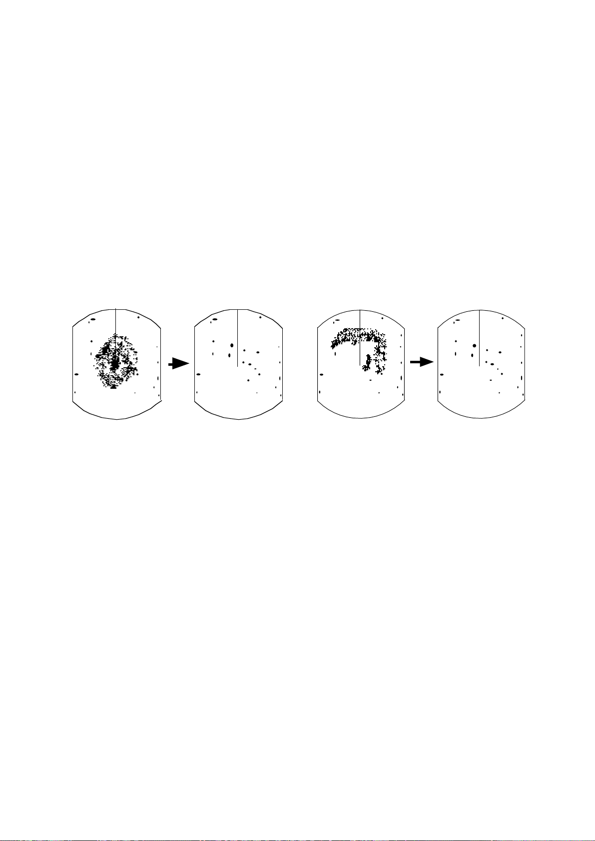
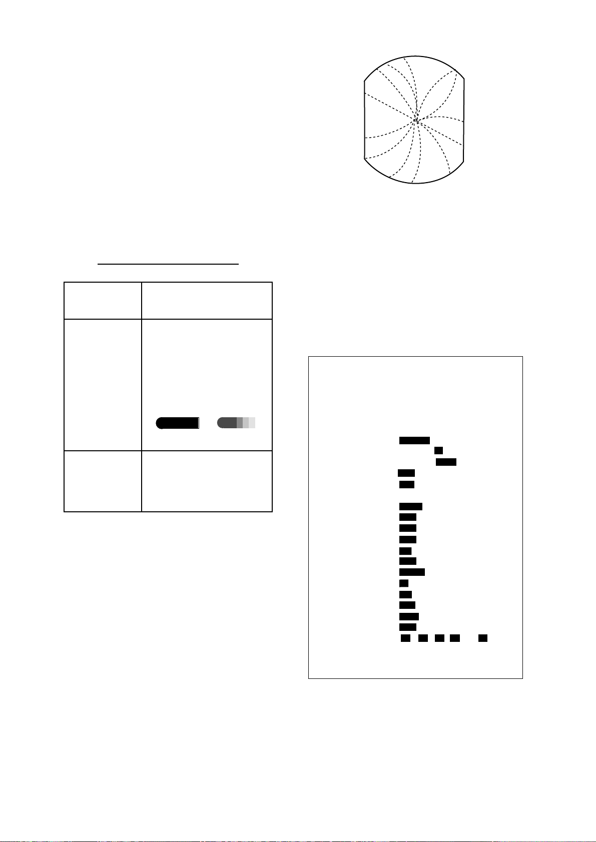
3.5 Suppressing Radar Interference
Radar interference may occur when near another shipborne radar operating in the same
frequency band as your radar. Its on-screen
appearance is many bright dots either scattered at random or in the form of dotted lines
extending from the center to the edge of the
display. Figure 3-5 illustrates interference in
the from of curved spokes. Interference effects are distinguishable form normal echoes
because they do not appear in the same place
on successive rotations of the antenna.
Figure 3-5 Radar interference
Four levels of interference are available, including off; IR1, IR2, IR3 and OFF. IR3 provides the highest level of rejection.
1. Press the [MENU] key.
2. Select “OTHER MENU” and press the
[ACQ/ENTER] key.
[ OTHERS ]
Select item by omnipad
and press ENTER key.
¡. Panel Dimmer
2 . Mark Brill
3 . HD Mark
4 . Characters
5 . Trail Tone
6 . Int Reject
7 . Pulselength
8 . Noise Reject
9 . Trail Time
10. Tune
11. Disp Data
12. WPT Mark
13. EBL Ref
14. VRM Unit
15. Watchman
16. STBY Disp
17. Guard Mode
18. Own Position
19. Cursor Posi
20. Alm sense LV
21. Dead Sector
22. Range
23. Self Test
24. Installation Setup
3M 6M 15M 30M Cont
2 £
1
1
1
1
Single
Off
Short
Off
15S
Auto
Off
Off
Rel
nm
Off
Norm
In
L/L
R/B
Low
Off
1/8
4 §
1/4
2
2
2
2
Multi
1
Long
On
30S
Manu
Nav
On
True
km
5M
Econo
Out
TD
L/L
Mid
On
1/2
3/4
8 ⁄2
3
3
3
3
2
1M
ARP
sm
10M
Nav
Hig
1
1.5
16 ¤4
¢
¢
¢
¢
3
All
20M
‹6
Figure 3-6 OTHER MENU
14
Page 26

3. Select “6. IntReject”.
Out alarm
4. Select level desired by operating the
omnipad.
5. Press the [ACQ/ENTER] key.
6. Press the [MENU] key to close the menu.
IR and level selected appears at the bottom
right corner on the display when the interference rejection circuit is turned on.
3.6 Selecting Pulsewidth
Pulsewidth is the transmission time of a single
radar pulse. The longer the pulsewidth the
greater the direction range capability , however
range accuracy and range resolution are reduced.
Pulsewidth can be selected to short or long
on the 1.5 and 3 nautical mile ranges.
1. Press the [MENU] key.
2. Select “OTHER MENU” and press the
[ACQ/ENTER] key.
3. Select “7. Pulselength”.
The alarm sounds on targets exiting the guard
zone. “G (OUT)” appears at the top right-hand
corner when the Out alarm is selected.
Dashed line:
no alarm
Guard
zone
IN ALARM
OUT ALARM
Figure 3-7 In and Out alarm
Setting a guard zone
Preparation
1. Press the [MENU] key, and then select
“OTHER MENU” and pressing the [ACQ/
ENTER] key.
2. Select “17. Guard Mode” and “In” (alarm
on target entering zone) or “Out” (alarm
on target exiting zone) by operating the
omnipad.
4. Select Short or Long by pressing the
omnipad.
5. Press the [ACQ/ENTER] key to select.
6. Press the [MENU] key to close the menu.
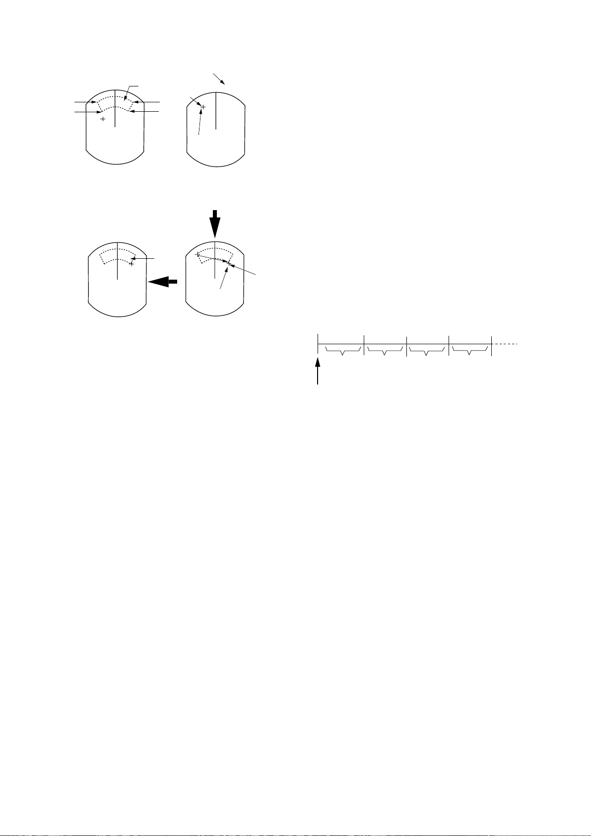
3.7 Guard Alarm
The guard alarm allows the operator to set the
desired range and bearing for a guard zone.
When ships, islands, landmasses, etc. violate
the guard zone an audible alarm sounds and
the offending target brinks to call the
operator’s attention.
Selection of guard zone type
The guard alarm can be set to sound when a
target either enters or exits the guard zone.
Y ou can select which type of guard alarm you
want through the menu.
3. Press the [ACQ/ENTER] key.
4. Press the [MENU] key to close the menu.
To set a guard zone
1. Mentally create the guard zone you want
to set.
2. Operate the omnipad to set the cursor on
point A or B. Press the [GUARD] key . “*G
(IN)” or “*G (OUT)”, with asterisk blinking, appears at the top right-hand corner of
the display . See Figure 3-8 (2). (The asterisk indicates the guard zone is partially set.)
3. Operate the omnipad to set the cursor on
point C or D. See Figure 3-8 (3).
4. Press the [GUARD] key. The asterisk disappears. See Figure 3-8 (4).
In alarm
The alarm sounds on targets entering the guard
zone. “G (IN)” appears at the top right-hand
corner when the In alarm is selected.
15
Page 27
¡ A target echo does not always mean a land-
Asterisk blinking
Guard zone
A
to set
B
A
D
C
* G (IN)
mass, reef, ships or surface objects but can
imply returns from sea surface or precipitation. As the level of these returns varies
with environment, the operator should
properly adjust the A/C SEA, A/C RAIN
Drag cursor
here.
and GAIN to be sure the alarm system does
not overlook target echoes.
Guard
zone
(2) Drag cursor to
top left corner of
zone and press
[GUARD].
G (IN)
Drag cursor
here.
(3) Drag cursor to
bottom right corner
of zone and press
[GUARD].
C
(1) Mentally create
the guard zone to set.
G (IN)
(4) Guard zone
completed.
Figure 3-8 How to set the guard zone
Silencing the audible alarm
Any radar targets violating the guard zone will
trigger the audible alarm. You can silence the
audible alarm by pressing the [GUARD] key .
When this is done, “G(ACKN)” replaces
“G(IN).” This means the alarm is
acknowledgrd. Press the key again to reactivate the alarm.
Cancelling the guard zone and guard
alarm
Press and hold down the [GUARD] key until
the guard zone disappears.
3.8 Watchman
The watchman function periodically transmits
the radar for minute to check for targets in a
guard zone. If it finds change in the zone from
the previous transmission it sounds the radar
continuously . This feature is useful when you
do not need the radar’ s function continuously
but want to be alerted to radar targets in a specific area.
Tx
1 min
Watchman
starts.
St-by
5, 10 or
20 min
Tx
1 min
Figure 3-9 How watchman works
How watchman works
When the time selected for the watchman rest
period has elapsed, the radar automatically
transmits for one minute to check the condition inside the guard zone. If there is no
change, the radar goes into stand-by
(“W ATCHMAN” appears during stand-by.) If
there is change, the radar sounds the audible
alarm, cancels the watchman function and
transmits continuously.
St-by
5, 10 or
20 min
Notes on the guard alarm
¡ The alarm is a useful anti-collision aid, but
does not relieve the operator of the responsibility to also keep a visual lookout for
possible collision situations.
¡ When the radar range is less than one half
of the guard zone range, the guard zone disappears and “G (IN)” or “G (OUT)” appears in inverse video. If this happens, raise
to re-display the guard zone.
16
Turning on watchman
1. Create a guard zone (usually 360 degrees)
with the guard alarm function.
2. Press the [MENU] key.
3. Select “OTHER MENU”.
4. Press the [ACQ/ENTER] key.
5. Select “15. Watchman”.
6. Press the omnipad to select watchman rest
period; 5 minutes, 10 minutes or 20 minutes.
Page 28
“WATCHMAN” appears at the top of the
screen, the radar transmits for one minute to
check for targets inside the guard zone, and
then the CR T shuts off and the radar goes into
stand-by.
Cancelling watchman
Go into the “OTHERS” menu, and set “15.
Watchman” for off.
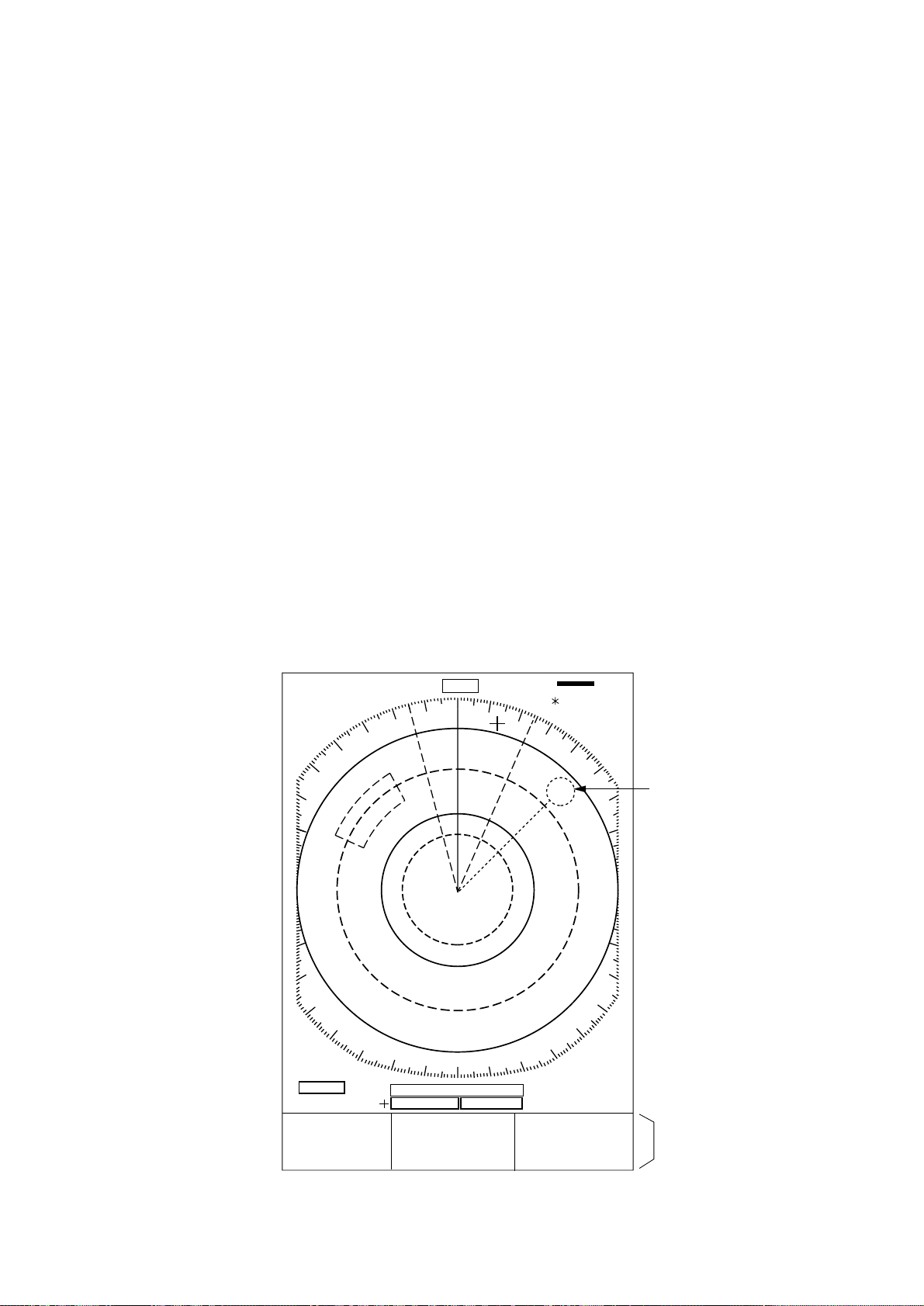
¡ range, bearing and time-to-go to both
waypoint selected on the navigator and the
cursor
¡ speed.
(If the navigation input includes destination
data, waypoint position is denoted on the radar display by a dashed ring.)
To turn navigation data on or off;
Note 1: Watchman can be used without a
guard zone.
Note 2: The alarm sounds just before the radar starts and stops transmitting.
3.9 Displaying Navigation Data
Navigation data can be displayed at the screen
bottom if this radar receives navigation input
in IEC 1162 format. Navigation data include
¡ position in latitude and longitude or Lo-
ran-C time difference
. 125
.
0625
SP
HU
NM
HDG 234.5°
1. Press the [MENU] key.
2. Select the “DISP DATA”.
3. Press the [ACQ/ENTER] key.
4. Press the [ACQ/ENTER] key to select the
message for Navigation display.
5. Prss the [ACQ/ENTER] key to set.
6. Press the [MENU] key to close the menu.
AUTO
TRAIL
25:38
30M
G (OUT)
ZOOM
ES1
A/C
AUTO
EBL
345.6 R
°
23.0 R
°
OWN SHIP
34° 56. 12N
135° 34. 56E
SPD 35.0KT
1.5 NM 0.06
13.5 R°
+ CURSOR
34° 29. 98N
136° 35. 77E
TTG 01:00
0.142NM
VRM
0.048NM
0.100NM
WAYPOINT
0.09 NM
50.0°M
TTG 00:20
Figure 3-10 Typical navigation data display
Waypoint Mark
Navigation
Data
17
Page 29

3.10 OTHER MENU Description
The following summarizes the OTHER MENU.
Table 3-2 OTHER MENU Description
Item Description
1. Panel Dimmer Select level of panel backlight.
2. Mark Brill Select brilliance of VRM, EBL, cursor, guard zone and WP marks.
3. HD Mark Select brilliance of heading mark.
4. Charactors Select brilliance of charactors.
5. Trail Tone Select brilliance of echo trails.
6. Int Reject Select level of interference rejection.
7. Pulselength Select pulselength for 1.5 and 3 mile ranges.
8. Noise Reject Select “On” to reject noise.
9. Trail Time Select the trail time.
10. Tune Select automatic or manual tuning.
To tune manually;
1.
Select “Menu” by the omnipad.
2.
Press the [ENTER] key to enable manual tuning.
3.
While pressing and holding down the [GAIN] control, operate
the omnipad.
Press the [ENTER] key.
4.
“MANUAL” appears at the top right-hand corner when manual
tuning is in effect.
11. Disp Data Select the down sourse to display.
12. WPT Mark Select “On” to display the waypoint mark.
13. EBL Ref select EBL reference for relative or true.
14. VRM Unit Select distance unit of VRM and cursor for nm, km or sm.
15. Watchman Turn watchman on (set rest period) or off.
16. STBY Disp Select the display on stand-by; display “STBY” or navigation data,
17. Guard Mode Select condition which triggers guard alarm; in or out.
18. Own Position Display the cursor position in strength whitch trigger guard alarm.
19. Cursor Posi Dispalay the cursor position in range/bearing or lat/long.
20. Alm sense LV Select minimau echo strength which triggers guard alarm.
21. Dead Sector Select “On” to display the dead sector.
22. Range Select ranges in use.
23. Self Test Test keys, ROM and RAM, check antenna rotation speed, and
24. Installation Setup Go to the installation setup menu.
or go into the economy mode.
display program no.
18
Page 30
3.11 Function Keys
3.12 Suppressing Noise
The function keys (F1 and F2) work like the
auto-dialing feature of a telephone, automatically executing the function assigned to them.
The function can be turned off by pressing
appropriate function key again.
Default settings
F1: Shift (brief press) or Zoom (long press)
F2: Ring brillience
How to register menu items
1. Press the [MENU] key.
2. Press [A/C SEA] (F1) or [A/C RAIN] (F2)
to open the function menu.
[ SETTING FOR F1 KNOB ]
SSel by omnipad & press ENT.S
<Press MENU key to escape>
SHIFT/
ZOOM
EBL
OFFSET
SHIFT ZOOM
Electrical noise can be suppressed by turning
on “8. NOISE REJ” on the OTHERS menu.
3.13 Adjusting Brilliance of Markers
“2. Mark Brill” on the OTHER menu adjusts
the brilliance of markers such as the cursor.
3.14 Outputting Target Position
Target position data can be output to the
navaid in IEC 1162 format. Press and hold
down the [TLL] key to output the data. This
function requires position data and heading
signal.
RINGS
INT
REJECT
TRAIL
ON/OFF
GUARD
IN/OUT
PANEL
DIMMER
EBL
REF
OWN
POSITN
HIS
TORY
MODE
NOISE
REJECT
TRAIL
TIME
ALARM
LEVEL
MARK
BRILL
VRM
UNIT
CUSOR
POSITN
COLLI
SION
PULSE
LENGTH
SECTOR
CHARA
CTERS
TALKER
VECTOR
LENGTH
Figure 3-11 Function menu
3. Select function desired.
DISP
DATA
TRAIL
TONE
DEAD
NAV
AUTO
ACQ
STBY
DISP
ECHO
STRTCH
TUNE
A/M
WATCH
MAN
OTHER
MENU
WPT
MARK
VECTOR
REF
NO
FNCTN
4. Press the [ACQ/ENTER] key.
5. Press the [MENU] key to close the menu.
19
Page 31
4. FALSE ECHOES
Occasionally false echoes appear on the screen
at positions where there is no target. In some
cases the effects can be reduced or eliminated.
The operator should familiarize himself or herself with the appearance and effects of these
false echoes, so as not to confuse them with
echoes from legitimate contacts.
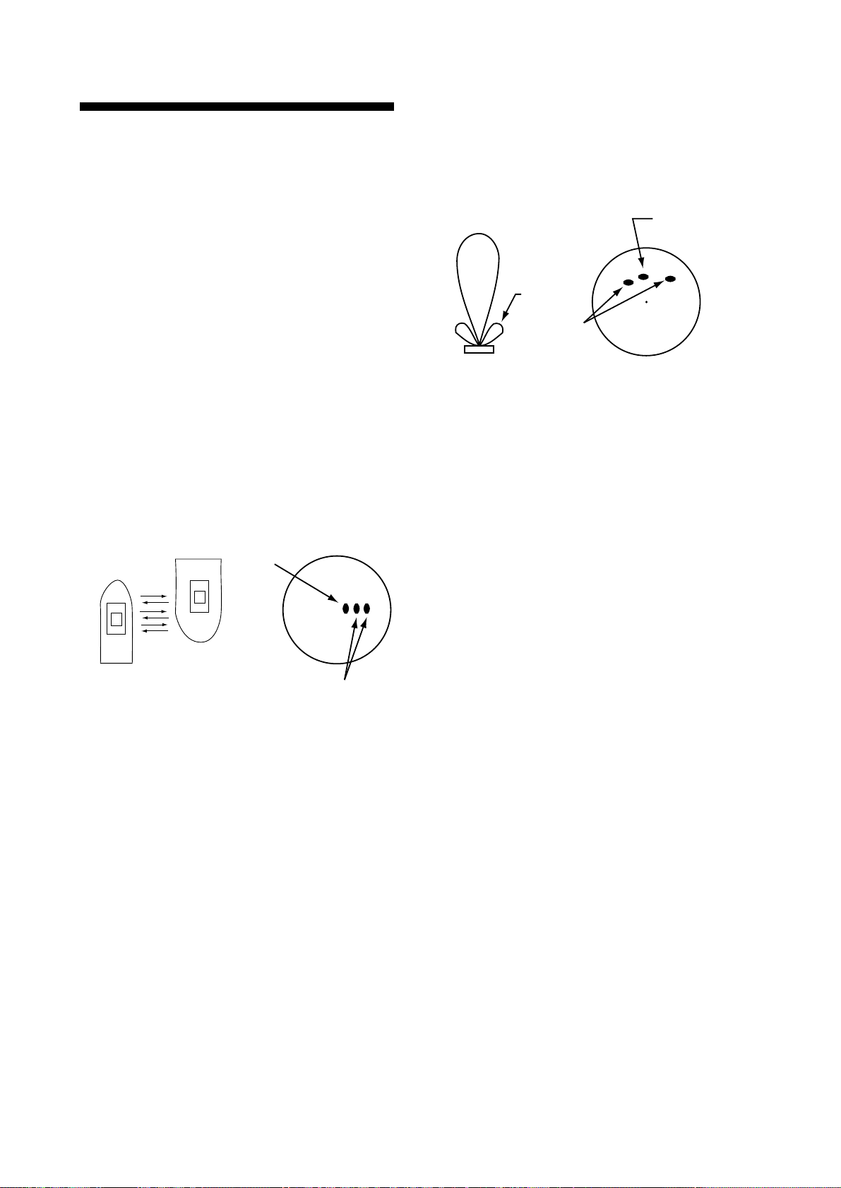
sented on both sides of the true echo at the same
range, as shown in Figure 4-2. Side-lobes show
usually only at short ranges and from strong targets. They can be reduced through careful reduction of the sensitivity or proper adjustment
of the A/C SEA.
Main-lobe
Side-lobe
True echo
4.1 Multiple Echoes
Multiple echoes occur when a short range,
strong echo is received from a ship, bridge, or
breakwater. A second, a third or more echoes
may be observed on the display at double, triple
or other multiples of the actual range of the target as shown in Figure 4-1. Multiple reflection
echoes can be reduced and often removed by
decreasing the sensitivity or properly adjusting
the A/C SEA.
True
echo
Own ship
Multiple
echo
Figure 4-1 Multiple echoes
4.2 Side-lobe Echoes
Sprious
target
Antenna
Figure 4-2 Side-lobe echoes
4.3 Indirect Echoes
Indirect echoes may be returned from either a
passing ship or returned from a reflecting surface on your own ship, for example, a stack. In
both cases, the echo will return from a legitimate contact to the antenna by the same indirect path. The echo will appear on the same
bearing of the reflected surface, but at the same
range as the direct echo. Figure 4-3 illustrates
the effect of an indirect echo. Indirect echoes
may be recognized as follows:
• they usually occur in a shadow sector
• they appear on the bearing of the obstruction but at the range of the legitimate contact
• when plotted, their movements are usually
abnormal, and
• their shapes may indicate they are not direct
echoes.
Every time the antenna rotates, some radiation
escapes on each side of the beam—called
“side-lobes.” If a target exists where it can be
detected by the side-lobes as well as the
main-lobe, the side-lobe echoes may be repre-
20
Page 32
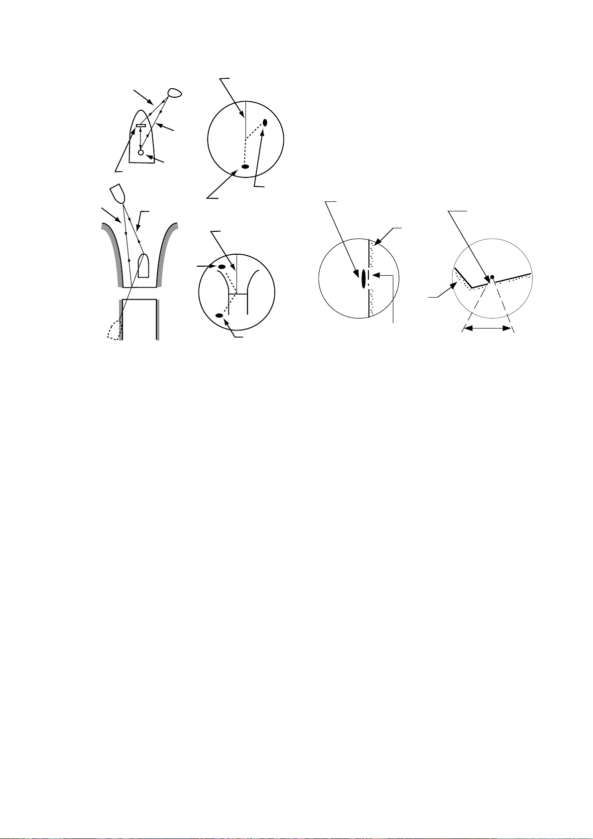
4.4 Blind and Shadow Sectors
Indirect
path
Direct
path
Antenna
Target
Indirect
echo
Own
ship
Bridge
Indirect
path
Obstruction
(mast, funnel.
etc.)
Direct
path
True
echo
Target
Heading
line
Indirect
echo
Heading
line
Indirect
echo
True
echo
Funnels, stacks, masts, or derricks in the path
of antenna may reduce the intensity of the radar beam. If the angle subtended at the antenna
is more than a few degrees a blind sector may
be produced. W ithin the blind sector small targets at close range may not be detected while
larger targets at much greater ranges may be
detected. See Figure 4-4.
Vessel taller
than wharf
Wharf
Wharf
Blind sector
(no echo)
Mast, etc. in
path of radar
beam
Size of blind sector
depends on target
size and range.
Figure 4-3 Indirect echoes
Figure 4-4 Blind and shadow sectors
21
Page 33
5. MAINTENANCE & TROUBLESHOOTING
This chapter tells you how to keep your radar
in good working order. Before reviewing this
chapter please read the safety information which
follows.
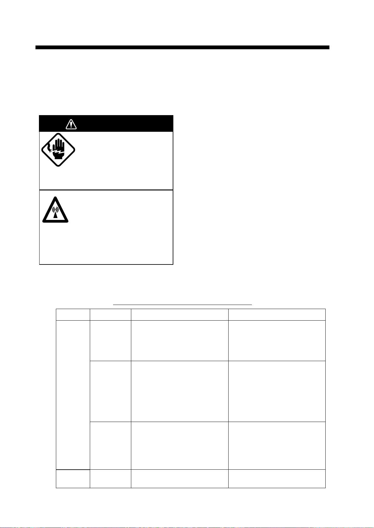
DANGER
Turn off the power before
performing any maintenance or
troubleshooting procedure.
Hazardous voltages can shock, burn or cause death.
Only qualified personnel totally famillier with electrical
circuits should work inside the units.
RF RADIATION HAZARD
The radar antenna emits high frequency
radio radiation which can be harmful,
particularly to your eyes.
Never look directly into the antenna from a distance of
less than two feet when the radar is in operation as
you could injure the cornea of your eyes. Always
make sure the radar is set to stand-by or is turned off
before starting work on the antenna unit.
5.1 Preventative Maintenance
Regular maintenance is important for good performance. Always keep the equipment as free
as possible from dirt, dust, and water splashes.
Make sure all screws securing the components
are properly tightened.
A maintenance program should be established
and should at least include the items listed in
table 5-1.
5.2 Replacing the Fuse
The fuse in the power cable protects the equipment against reverse polarity or ship’s mains,
overcurrent, and equipment fault. If the fuse
blows, find the cause before replacing it. Never
use an incorrect fuse – serious damage to equipment may result and void the warranty.
12 V: 10 A fuse
24/32 V: 5 A fuse
Table 5-1 Recommended maintenance program
Period Item Check point Remarks
3 to 6
months
6 months
to 1 year
Exposed
nuts and
bolts on
antenna unit
Antenna
radiator
(1932/1942)
Radome
cover
(1832)
Display unit
connectors
Check for corroded or loosened
nuts and bolts. If necessary,
clean and repaint them thickly.
Replace them if heavily
corroded.
Check for dirt and cracks on
radiator surface. Thick dirt
should be wiped off with soft
cloth dampened with fresh
water. If a crack is found, apply a
slight amount of sealing
compound or adhesive as a
temporary remedy, then call for
Check for wear. Permanent
damage to the antenna's internal
circuitry will result if water leaks
into the radome.
Check for tight connection and
corrosion.
Sealing compound may be used
instead of paint. Apply a small
amount of grease between nuts
and bolts for easy removal in
future.
Do not use plastic solvent
(acetone) for cleaning. If you
need to remove ice from
antenna unit, use a wooden
hammer or plastic head
hammer. Crack on the unit may
cause water ingress, causing
serious damages to internal
If a crack is found it should be
temporarily repaired by using a
small amount of sealing
compound or adhesive. You
should then contact your dealer
for service.
If corroded, contact your dealer
for replacement.
22
Page 34

5.3 Troubleshooting
T able 5-2 contains simple troubleshooting procedures which you can follow to try to restore
normal operation. If you cannot restore normal
operation, do not attempt to check inside any
unit of the radar system. Any repair work is best
left to a qualified technician.
Table 5-2 Troubleshooting table
If... But... Then...
you pressed the
[POWER] key to
turn on the radar
the radar has
warmed up and you
pressed the
[STBY TX] key to
transmit
you have adjusted
the gain with A/C
RAIN and A/C SEA
off
the control panel
does not light
nothing appears on
the display or display
contrast is poor
characters are
distorted
the antenna does not
rotate
characters and
indications are
abnormal
neither noise nor
targets appear
(indications and
markers do)
neither indications nor
markers appear
(noise and targets do)
• try adjusting the control panel back lighting on the OTHERS menu.
• battery may have discharged.
• check fuse in power cable.
• try adjusting the brilliance.
• request service.
• the problem may be in antenna unit.
Request service.
• have a qualified technician check the
set.
• check signal cable for damage.
• check signal cable for damage.
the sweep (radial line
sweeping around the
display) is not
synchronized with
antenna rotation
there is no change in
sensitivity
a key is pressed nothing happens • key may be faulty. Request service.
• the problem may be in the antenna
unit. Request service.
• request service.
23
Page 35

5.4 Self Test
The self test facility checks the keyboard, ROM
and RAM for proper operation.
1. Press the [MENU] key.
2. Select “OTHER MENU”.
3. Select “23. Self Test” and press the [ACQ/
ENTER] key . The following display appears.
[ Self Test ]
Key test: Press each key and
check on-screen indication
lights.
ARP-10 TEST
ROM OK 18990871xx
RAM OK
SPEED OK NAV 0.0KT
COURSE OK 167.6°
l
TRIGGER NG
VIDEO NG
BP OK
HP OK
MIN-HIT 0003
SCAN-TIME 0854
MAN-ACQ 00
AUTO-ACQ 00
FE-DATA1 0000
FE-DATA2 0000
7. Press the [MENU] key to back to the selftest
menu.
8. To escape from the test, press the [MENU]
key.
5.5 Life Expectancy of
Magnetron
The following table shows the life expectancy
of the magnetron.
Table 5-3 Life expectancy of magnetron
Model Type Code no. Life expectancy
E3571 000-137-527
1832/
MG5248 000-116-121
1932
MAF1421B –
E3560 000-139-050
1942
MG5389 000-135-146
2,000 - 3,000 hours
(Including stand-by)
Program No.: 0359139-1XX
ROM :NG
RAM :OK
Hours in use: 000006.9H
Tx hours : 000001.1H
<Press MENU for OTHERS menu.>
OK
Figure 5-1 Self test screen
4. The ROM and RAM are automatically
checked. If NG (No Good) appears to the
right of ROM or RAM indication, contact
your dealer for advice. ARP-10 TEST results
appear only when optional ARP-10 board is
mounted.
5. To check the keyboard, press any key except the omnipad, ACQ and power keys. Its
corresponding location on the display lights
in black if the key is operating properly.
6. Press the [ACQ] key to check the display
circuit. The following pattern should appear .
24
Figure 5-2 Test pattern
Page 36
6. INSTALLATION
This chapter provides the procedures necessary for installation. Installation mainly consists of the following:
¡ siting and mounting the display unit and
antenna unit
¡ connection of the signal cable and the
power cable
¡ establishing the ground
¡ checking the installation, and
¡ adjustments.
6.1 Antenna Unit Installation
Siting, handling considerations
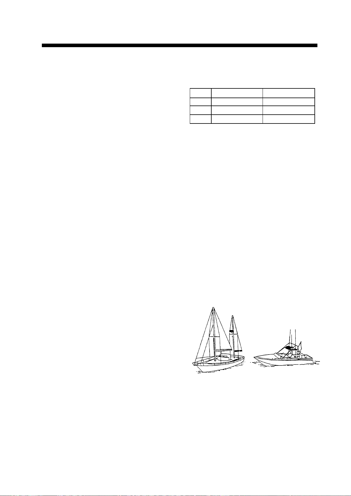
¡ The antenna unit is generally installed either
on top of the wheelhouse or on the radar mast
on a suitable platform. Locate the antenna
unit where there is a good all-round view
rigging intercepting the scanning beam. Any
obstruction will cause shadow and blind
sectors. A mast for instance, with a diameter
considerably less than the width of the
radicator, will cause only a small blind sector, but a horizontal spreader or crosstrees in
the same horizontal plane as the antenna unit
would be a much more serious obstruction;
you would need to place the antenna unit well
above or below it.
¡ The compass safe distance should be ob-
served to prevent deviation of the magnetic
compass.
Model Standard compass Steering compass
1832 0.9 m 0.7 m
1932 1.1 m 0.8 m
1942 1.0 m 0.74 m
¡ Do not paint the radome (Model 1832) or
radiator aperture (Model 1932, 1942), to
ensure proper emission of the radar waves.
¡ When this radar is to be installed on lar ger
vessels, consider the following points:
(1) The signal cable run between the an-
tenna and the display comes in lengths
of 10 m, 15 m, 20 m and 30 m. Whatever length is used it must be unbroken; namely, no splicing allowed.
(2) Deposits and fumes from a funnel or
other exhaust vent can adversely affect
the aerial performance and hot gases
may distort the radiator portion. The
antenna unit must not be mounted
where the temperature is more than
70°C.
Mounting (Model 1832)
¡ It is rarely possible to place the antenna unit
where a completely clear view in all direction
is available. Thus, you should determine the
angular width and relative bearing of any
shadow sectors for their influence on the
radar at the first opportunity after fitting.
(The method of determining blind and
shadow sectors appears later in this chapter.)
¡ If you have a radio direction finder on your
boat, local its antenna clear of the antenna
unit, to prevent interference to the direction
finder. A separation of more than two meters
is recommended.
¡ To lessen the chance of picking up electri-
cal interference, avoid where possible routing the signal cable near other onboard
electrical equipment. Also avoid running
the cable in parallel with power cables.
Figure 6-1 Typical antenna unit location
Unpacking the antenna unit
1. Open the antenna unit packing box carefully.
2. Unbolt the four bolts at the base of the radome to remove the radome cover.
25
Page 37
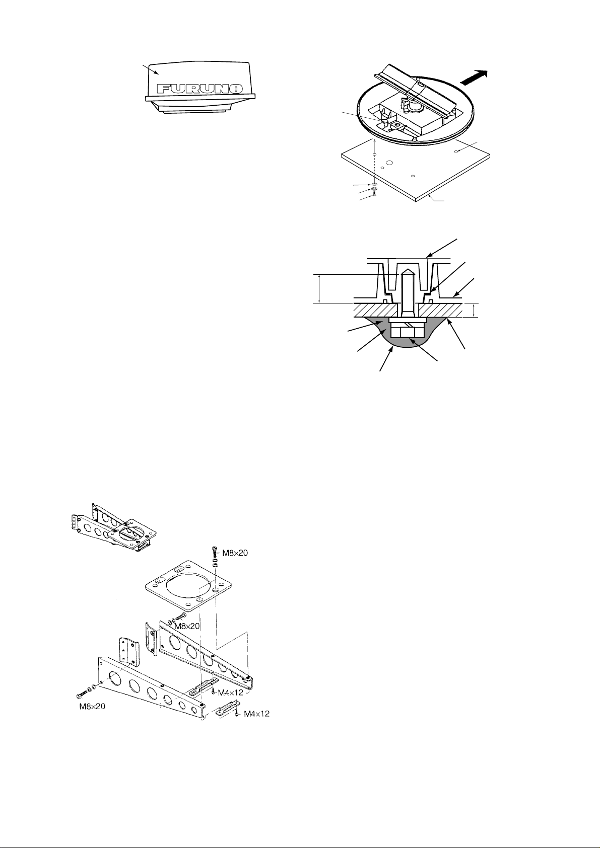
Radome cover
Figure 6-2 Antenna unit
Mounting platform
CABLE
ENTRY
SHIP'S BOW
4-Ø12 HOLES
Holes for antenna unit:
The mounting surface must be parallel with
the waterline and provided with five holes
whose dimensions are shown in the outline
drawing attached at the end of this manual.
The unit is adjusted so a target echo returned
from the bow direction will be shown on the
zero degree (heading line) position on the
screen. When drilling holes, be sure they are
parallel with the fore and aft line.
3. Prepare a platform of 5 to 10 millimeters
in thickness for the antenna unit. (A mounting bracket for mounting the antenna unit
on a sailboat mast is optionally available.
See the below for details.) Find the cable
entry on the radome base. Next, position
the radome base so the cable entry faces
the stern direction. This alignment must be
as accurate as possible. Fasten the radome
base to the mounting platform with four
each of M10 x 25 hex bolts, flat washers
and spring washers.
Mask size;
φ70 to φ125 mm
FLAT WASHER
SPRING WASHER
M10 X 25 HEX BOLT
Effective
thread length
25 mm
Flat
washer
Spring
washer
Apply silicone sealant
PLATFORM
Antenna base plate
Packing
Radome
5 - 10 mm
Platform
M10 x 25
Hex bolt
Figure 6-4 How to fasten the radome base
to the mounting platform
Wiring and final preparation
4. Drill a hole of at least 20 millimeters diameter through the deck or bulkhead to run
the signal cable between the antenna unit
and the display unit. (T o prevent electrical
interference avoid running the signal cable
near other electrical equipment and in parallel with power cables.) Pass the cable
through the hole. Then, seal the hole with
sealing compound for waterproofing.
5. Remove the shield cover in the radome.
Type: OP03-92
Code no.: 008-445-070
Figure 6-3 Assembling the sailboat mast
mounting bracket (option)
26
Page 38
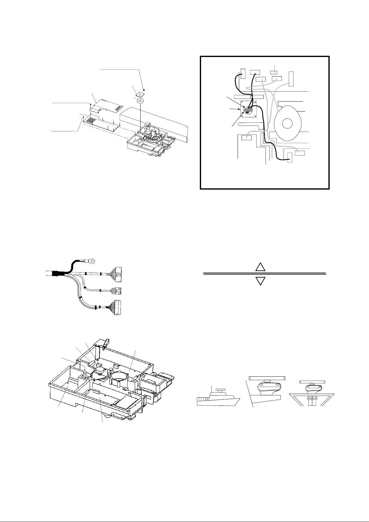
6. Remove the cable clamping plate by unfastening four screws and removing a gasket.
10. Attach the EMC core supplied as shown
below.
Pan head screws
M4x8 4 pcs.
Cable clamping plate
Pan head
screws
M4x8 7 pcs.
Shield cover
Pan head
screws
M4x8 7 pcs.
Shield cover
Gasket
Figure 6-5 Antenna unit, inside view
7. Pass the cable through the hole at the bottom of the radome base.
8. Secure the cable with the cable clamping
plate and gasket. Ground the shield and
vinyl wire by one of the screws of the cable
clamping plate.
9. Connect the wire to the RF unit.
to one of the screws
of the cable clamping plate
9-pin connector:
to J801 on MD-9208
4-pin connector:
to J802 on MD-9208
13-pin connector:
to J611 on IF-9214
Figure 6-6 Signal cable, antenna unit side
J802
J801
Cable
entry
MD-9208
J801
Cable
entrance
Cable
clamping
plate
EMC core
E04SS251512
(Above cable
clamping
plate)
PTU-9335
J1
J802
J804
J805
J803
Motor
J611
MD9208
J806
J613
IF9214
Figure 6-8 How to attach EMC cor e
11. Fix the shield cover. Do not pinch the
cable.
12. Attach the radome cover, aligning triangle
mark on radome cover with that on radome base.
Radome cover
Radome base
Figure 6-9 How to position the radome
cover
13. Loosely fasten the radome fixing bolts.
You will tighten them after confirming
magnetron heater voltage.
Mounting (Model 1932, 1942)
PTU-9335
J611
IF-9214
Figure 6-7 RF unit
Figure 6-10 Typical antenna unit mounting
locations
1. Drill four fixing bolt holes (13 millimeters
dia.), one cable entry hole (approx. 50 millimeters dia.) in the mounting platform. See
the outline drawing.
27
Page 39
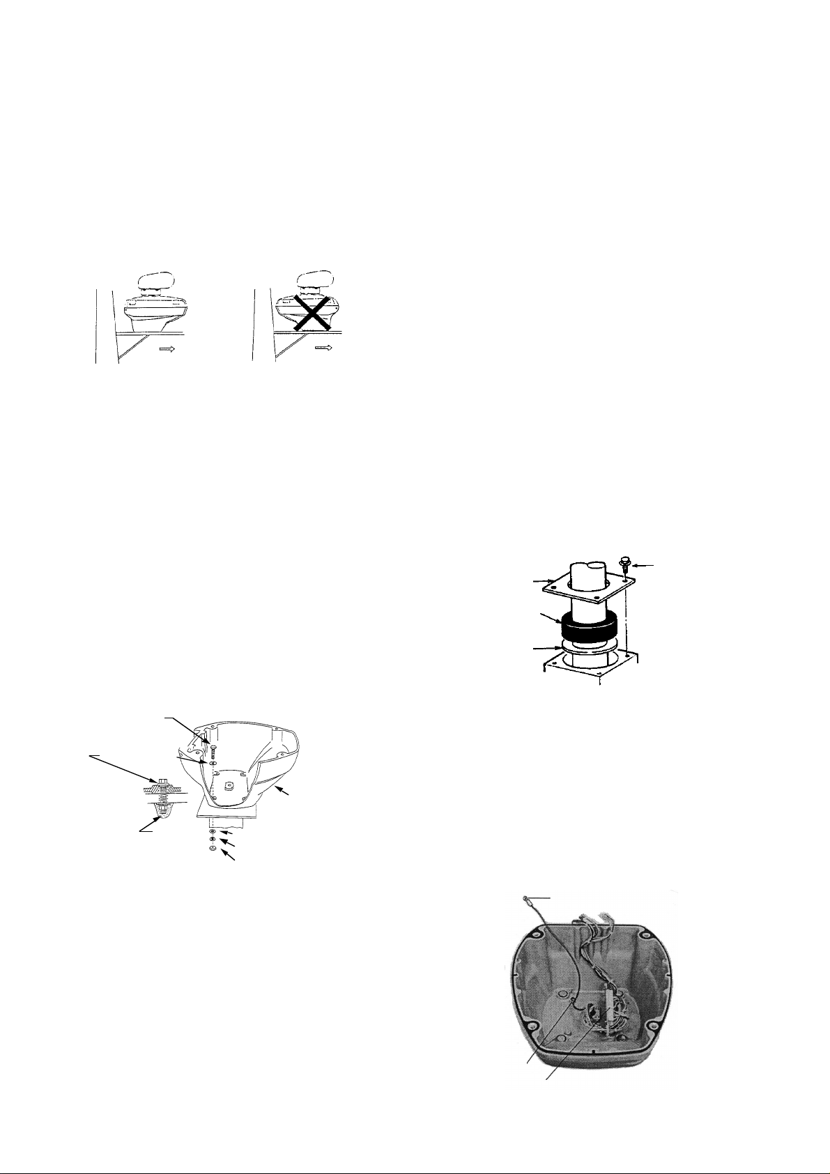
2. Detach the antenna housing cover from the
antenna housing by loosening four fixing
bolts. The antenna housing cover fitted with
the transceiver module can be stored in a
convenient place until the wiring to the antenna unit is done.
3. Place the antenna housing on the mounting platform and orient it as shown in Figure 6-11.
Ship's
bow
Ship's
bow
Figure 6-11 How to orient the antenna unit
Connections
Only the signal cable runs from the display
unit to the antenna unit. Make the hole for
passing the cable through the bulkhead or deck
at least 20 millimeters diameter. In order to
minimize the chance of picking up electrical
interference, avoid where possible routing the
signal cable near other onboard electrical
equipment. Also, avoid running the cable in
parallel with power cables. Pass the cable
through the hole and apply sealing compound
around the hole for waterproofing.
The procedure for connecting the signal cable
to the antenna unit is as following.
1. Through a pipe or waterproof cable grand
fitted on the wheelhouse top or bulkhead.
4. Insert four M12 x 60 hex head bolts with
the seal washers from inside the antenna
housing, to prevent the bolts from contacting the transceiver module. Install the seal
washer with the larger diameter next to the
head of the bolt. Coat flat and spring washers and nuts and then use them to fasten
the antenna housing to the mounting platform. Finally, coat exposed parts of nuts,
bolts and flat and spring washers as shown
in Figure 6-12.
Note: Tighten the bolts by their nuts to prevent damage to the seal washer. Do not turn
the bolts to secure the antenna housing.
Hex head bolt
(M12 x 60)
Seal washer
Scanner
housing
Silicone
sealant
Flat washer
Spring washer
Hex head nut
2. Unfasten four screws at bottom of the scanner base to remove the cable gland assembly.
3. Pass the signal cable through the antenna
base and the cable gland assembly (removed in step 2.)
4-M4x10
CLAMP PLATE
PACKING
FLAT
WASHER
Figure 6-13 Passing the signal cable
through the antenna housing
4. Fasten the cable gland assembly.
5. Connect the lead wires to R TB-9100 in the
antenna housing by referring to the Interconnection Diagram. Fasten the ground
washer at the bottom of the antenna housing as shown in Figure 6-13.
Figure 6-12 How to mount the antenna
housing
28
GROUND WIRE
Fasten
shield here.
RTB-9100
Figure 6-14 Connection in the antenna
housing
Page 40
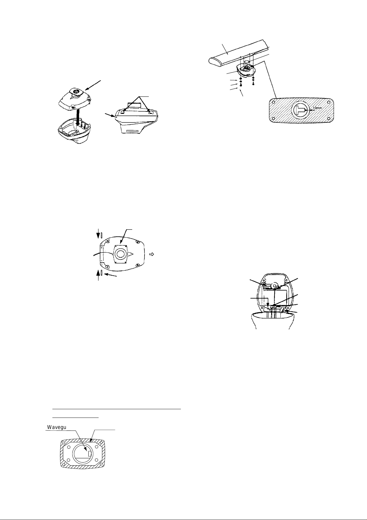
Final preparation
1. Place the antenna housing cover on the
housing. Loosely fasten the four fixing
bolts on the cover.
Scanner housing
cover
Fixing
holes
Pinning
hole
Figure 6-15 Fastening the antenna
housing cover
2. Apply grease to the two slot pins. Using a
wooden hammer to prevent damage to
paint, insert slotted pins into the pinning
holes until the pin head is flush with the
scanner housing surface.
Radiator
bracket
Face in
stern direction.
Ship’s
bow
Scanner
radiator
Radiator bracket
Flat washer
Spring washer
Hex head bolt
(M8 x 30)
Coat bolts with
silicone sealant.
Apply silicone sealant
into threaded holes.
O-ring
Note: Apply anticorrosive sealant
to hached areas, antenna bracket
for XN12A type radiator.
Figure 6-18 Fastening the radiator to the
radiator bracket
4. Open the antenna housing cover and fix the
stay as shown in Figure 6-19.
5. One end of the cable with 15-, 9- and 7way plugs has already been connected to
RTB-9100 inside the scanner housing.
Mate the 15- and 9-way plugs with jacks
J812 and J811 on the transceiver module,
respectively. Connect the 7-way plug to
jack J701 on the MP Board. Secure the
cable between R TB-9100 and J701 with the
cable tie as shown in Figure 6-19.
Slotted pin
Figure 6-16 How to insert slot pins
3. Now is the time to fix the radiator to the
radiator bracket. Apply anticorrosive sealant (silicone sealant) to hatched areas, to
prevent corrosion. See the figure below.
Apply silicone sealant into threaded holes
on the scanner radiator. Remove the cap
on the radiator bracket and orient the radiator bracket as shown in Figure 6-13.
Apply grease to the O-ring and set it to the
center of the radiator bracket. Coat the radiator fixing bolts with silicone sealant.
Fasten the radiator to the radiator bracket
with the FURUNO logo on the radiator facing ship’s bow.
Waveguide
Groove
Note: Apply anticorrosive
sealant to hatched areas,
antenna radiator bottom
view of XN8 type radiator.
MP Board
Fasten ground
wire here.
Cable
tie
J812
J811
Stay
Figure 6-19 Antenna unit, cover opened
6. Fasten the ground wire (black) of the signal cable to the chassis as shown in Figure
6-19.
7. Loosely fasten the antenna housing cover.
You will tighten the fixing bolts after confirming magnetron heater voltage.
Figure 6-17 How to coat radiator with
silicone sealant for XN8 type radiator
29
Page 41

6.2 Display Unit Installation
Mounting considerations
Mounting
The display unit is designed to be mounted
on a tabletop or bulkhead.
When selecting a mounting location for the
display unit keep in mind the following points.
¡ Even though the display unit is waterproof,
it is recommended that the display unit
must be mounted inside an enclosed cabinet.
¡ Provide adequate space behind and around
the unit to permit circulation of air and to
provide convenient access to the rear connectors.
¡ Even though the picture is quite legible
even in bright sunlight, keep the display
unit out of direct sunlight or at least shaded
because of heat that can build up inside the
cabinet.
¡ Locate the display unit in a position where
you can view and operate it conveniently
but where there is no danger of salt or fresh
water spray or immersion.
¡ The orientation of the display unit should
be so the radar screen is viewed while the
operator is facing in the direction of the
bow. This makes determination of your
position much easier.
¡ Make sure you allow enough clearance
both to get to the connectors behind the unit
and to allow you to get your hands in on
both sides to loosen or tighten the mounting knobs. Make sure you leave at least a
foot or so of “service loop” of cables behind the unit so it can be pulled forward
for servicing or easy removal of the connectors.
¡ The compass safe distance of 0.8 meters
(standard compass) and 0.6 meters (steering compass) should be observed to prevent deviation of the magnetic compass.
¡ Even though the display unit meets water-
proof standard IPX-5, the connection of external buzzer, radar plotter and/or remote
display can affect waterproofness. Watertight integrity cannot be guaranteed. When
these modification has been done, the display unit should not be mounted where exposed.
1. Using the hangar as a template, mark screw
locations in the mounting location.
2. Fix the hanger to the mounting location
with five M6 tapping screws (supplied).
3. Fit the knob bolts to the display unit. Install the display unit in the hunger . T ighten
the knob bolts securely.
Connections
1. Connect the power cable to the power cable
connector on the rear of the display unit.
2. Connect the signal cable to connector DJ1 on the rear of the display unit.
3. Run a ground wire (local supply) between
the ground terminal on the rear of the display unit and the ship’s superstructure.
Navigation aid, video sounder connection
If your navigation aid can output data in
IEC1162(NMEA 0183) data format, your
vessel's position in latitude and longitude, the
range and bearing to waypoint, speed and
course may be input to this radar, and be seen
on the screen.
Further if your video sounder can output depth
in IEC1162 (NMEA 0183) data format, depth
can be displayed on the radar screen.
You will need an NMEA cable:
Type Code no. Remarks
MJ-A6SPF0012-050 000-134-424 6P-6P (5m)
MJ-A6SPF0012-100 000-133-817 6P-6P (10m)
MJ-A6SPF0003-050 000-117-603 w/connector
MJ-A6SPF0009-100 000-125-236 w/connector
This radar can output NA V data received from
a navaid to an echosounder.
SPU9211
1832/1932/1942
INT9213
J1352 (NMEA)
(TLL)
J1354
Navaid
Echosounder
30
Page 42

Heading Sensor Connection
Heading signal can be connected to the
“HDG” connector.
Type Code no. Remarks
MJ-A6SPF0007-100 000-125-237 6P-6P 10m
MJ-A6SPF0009-100 000-125-236 w/connector
MJ-A6SPF0003-050 000-117-603 w/connector
Input/Output Data List
(10m)
(5m)
Model
FCV561M2 J1 183 (1.5) 4 In/Out
FCV581 NMEA 183 (1.5) 4 In/Out
FCV582 NMEA 183 (1.5) 4 In/Out
FCV291 NMEA 183 (1.5/2.0) 6 In/Out
FCV292 NMEA 183 (1.5/2.0) 6 In/Out
FCV668 NMEA 183 (1.5) 4 In/Out
GP1810 IN/OUT 183 (1.5/2.0) 6 In/Out
GP3100M2 IN/OUT 183 (1.5) 6 In/Out
GP8000M2 NMEA 183 (1.5/2.0) 4 In/Out
PS8000M2 NMEA 183 (1.5/2.0) 4 In/Out
GP80 DATA1 183 (1.5/2.0) 6 In/Out
GP80 DATA2 183 (1.5/2.0) 6 In/Out
GP1800M2 IN/OUT 183 (1.5/2.0) 6 In/Out
Connector
Name
Data Pin In/Out
Note: All plotter in the table except the GP1800M2 can receive TLL data.
31
Page 43
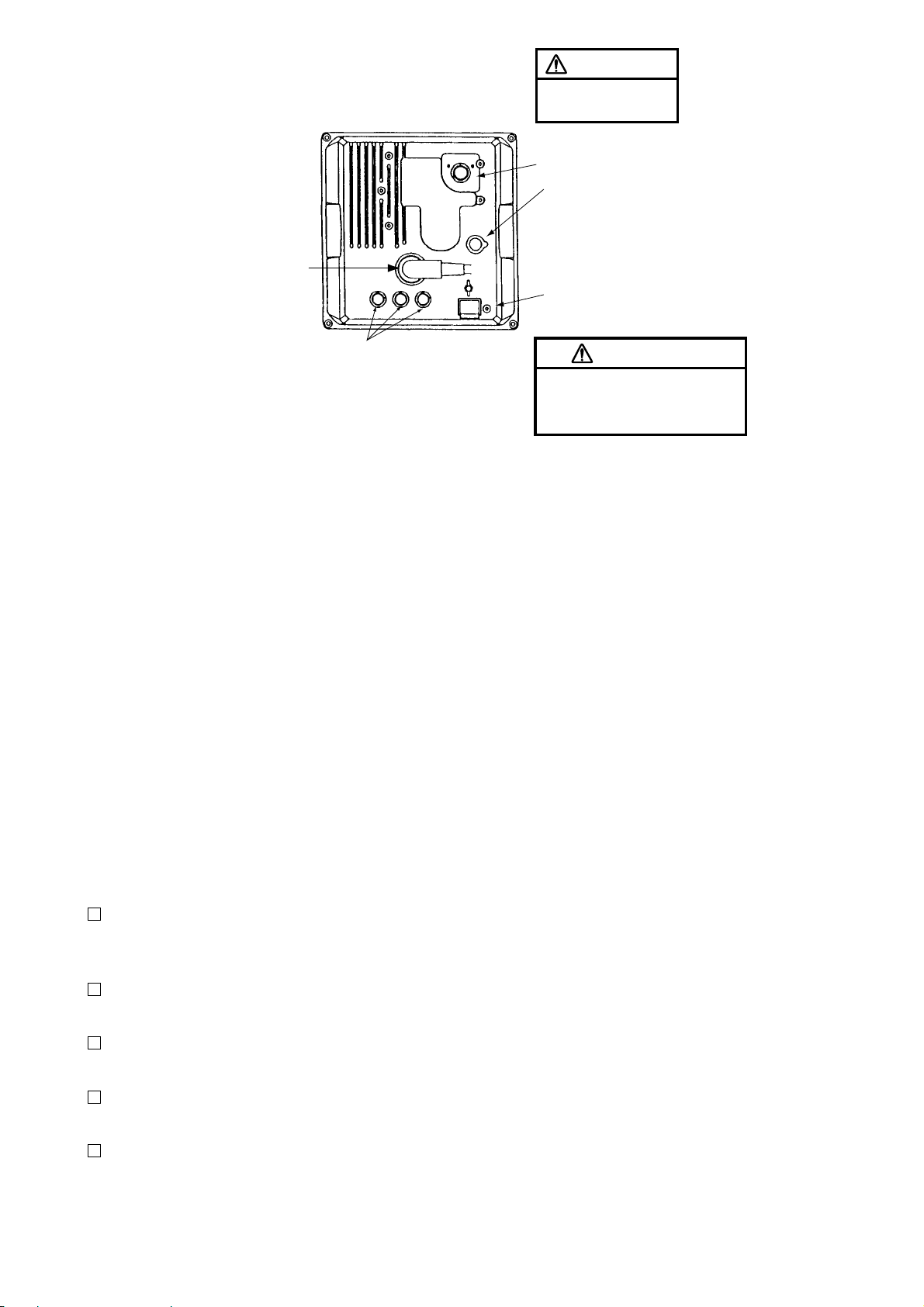
Signal cable connector
(DJ-1, waterproof)
Left: HDG connector
Mid: NMEA connector (for NAV)
Right:NMEA connector (for E/S)
Figure 6-20 Connections on the display unit
CAUTION
Replace the fuses to
5 A for 24/32 VDC set.
Power cable connector
External equipment
connector
(To be used for Remote
Display, External Alarm
Buzzer, OP03-21 and
Radar Plotter, RP-110)
Ground terminal
CAUTION
Ground the equipment. Ungrounded
equipment can give off or receive
electro-magnetic interference or give
electrical shock.
6.3 Exchange of Fuse for 24/32V Power Supply
The power cable comes with a 10A fuse in
the fuse holder. This fuse is for use with a
12V DC power supply. For 24V/32V DC
power supply, replace the fuse with the 5A
fuse (supplied) and attach 5A label (supplied)
to fuse holder.
6.4 Checking the Installation
After completing the installation, it is a good
idea to recheck it to be sure all steps were
correctly done. Use the table 6-1 to check the
installation.
Tick box
The signal cable is securely retained
against the mast or mounting platform and
is free of interference from running rigging.
The cable gland or entry on the deck, if
provided, is waterproofed.
The power connections to the battery are
of correct polarity.
The plugs at the rear of the display unit
are tightly fastened.
The fuse in the power cable is 10A (12V)
or 5A (24V/32V DC).
6.5 Adjustments
This section covers adjustment of the radar
after installation. You will need to
¡ adjust tune/video amplifier level input
¡ enter antenna height
¡ align heading
¡ adjust sweep timing
¡ adjust main bang suppression
¡ setting a blanking area, and
¡ confirm magnetron heater voltage.
These adjustments are done through the radar
install menus.
Preparation
1. Turn of f the radar. While pressing and holding down the [GAIN] control (at least three
seconds), press the [POWER] key.
2. Press the [MENU] key, and select “OTHERS” by using the omnipad, and pressing
[ACQ/ENTER] key.
3. Select “24. Installation setup”.
4. Press the [ACQ/ENTER] key to open the
installation setup menu.
32
Page 44
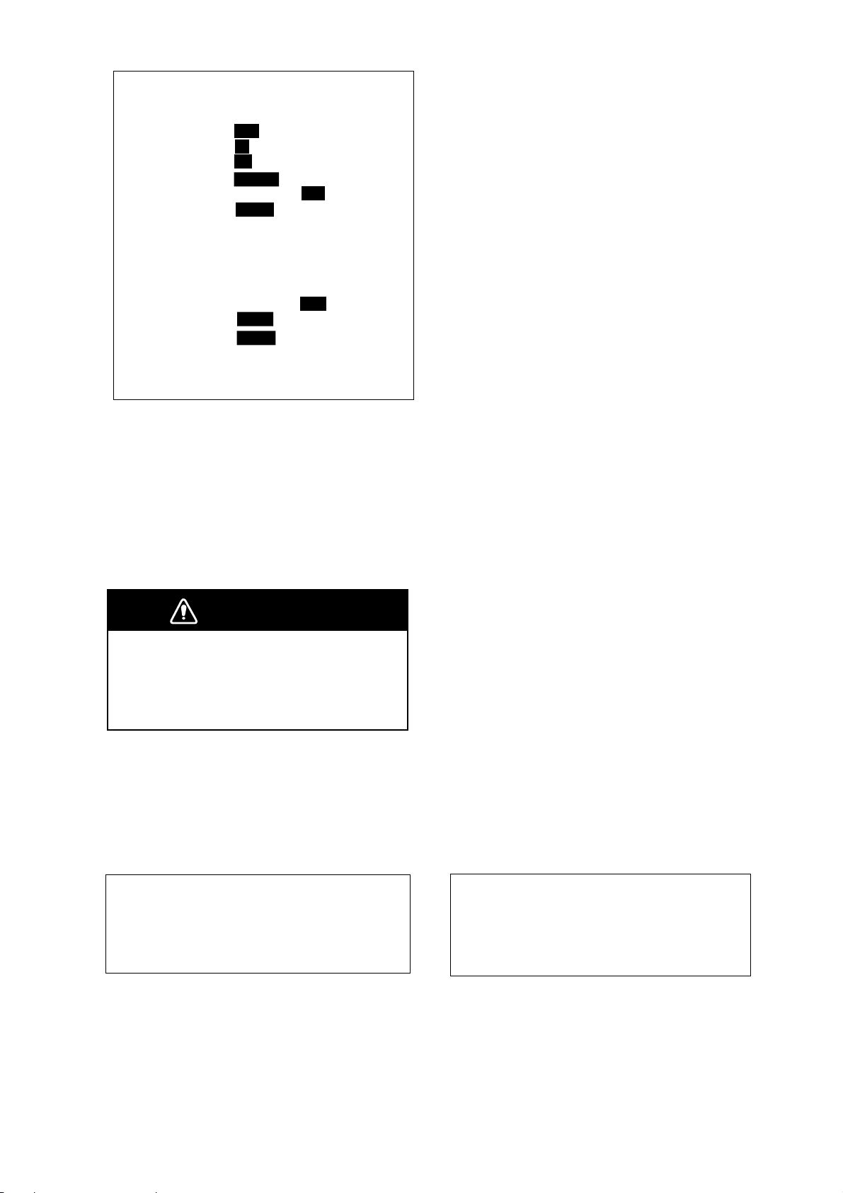
[ Installation Setup ]
Select item by omnipad
and ress ENTER key.
¡. Nav Talker
2 . Depth Unit
3 . Temp Unit
4 . Hdg Sensor
5 . Key Beep
6 . Ant on Tx
7 . Dead Sector
8 . Tuned/Video
9 . Heading Alignment
10. Sweep Timing
11. MBS Adjustment
12. Ant Height
13. STC Curve
14. Ope Mode
15. Hours in Use
16. Tx Hours
Auto Adjustment
Adjustment
All
m
˚C
Magnet
Off
Rotate
180˚~180˚
Low
Sharp
Master
000001.5H
000000.0H
GPS
fa
˚F
Gyro
On
Stop
Mid
Std
Slave
LC
ft
Hig
Gntl
Figure 6-21 Installation setup menu
Adjusting tune/video
Do the following to adjust tune and video amplifier level input.
1. Press the [ST BY/TX] key to transmit.
WARNING
Before transmitting the radar make sure
no one is near the antenna unit, to prevent the potential risk of being struck
by the rotating antenna and exposure
to RF radiation hazard.
2. On the Installation setup menu, select “8.
Tune/Video Adjustment” and press the
[ACQ/ENTER] key.
3. The unit automatically adjusts, displaying
the following message.
Entering antenna height
The STC curve changes with respect to antenna height above the waterline. Enter antenna height above the waterline to optimize
the STC curve.
1. Select “12. Antenna Height” on the installation setup menu and press the [ACQ/ENTER] key.
2. Operate the omnipad to select antenna
height above the waterline; Low (~3 m),
Mid (3~6 m) or High (6~10 m).
3. Press the [ACQ/ENTER] key.
Aligning heading
(Adjustment sector:0~359.90)
You have mounted the antenna unit facing
straight ahead in the direction of the bow.
Therefore, a small but conspicuous target dead
ahead visually should appear on the heading
line (zero degrees).
In practice, you will probably observe some
small error on the display because of the difficulty in achieving accurate initial positioning of the antenna unit. The following
adjustment will compensate for this error.
1. Identify a suitable target (for example, ship
or buoy) at a range between 0.125 to 0.25
nautical miles, preferably near the heading mark. To lessen error, keep echoes in
the outer half of the picture by changing
the range. Also, be sure the zoom and off
center functions are off.
2. Select “9. Heading Alignment” on the installation setup menu and press the [ACQ/
ENTER] key. The following message appears on the display.
[ Tune/Video Auto Adjustment ]
Now under correction.
Return to illustration setup.
menu after the correction.
Figure 6-22 Tune/Video Auto
Adjustment messages
4. When adjustment is completed, the messages disappears.
[ Heading alignment ]
Set EBL1 to center of target
dead ahead and press ENTER.
Correction 0.0°
<Press MENU for inst setup>
Figure 6-23 Heading alignment message
3. Operate the omnipad to bisect target selected at step 1 with the heading line.
4. Press the [ACQ/ENTER] key.
33
Page 45
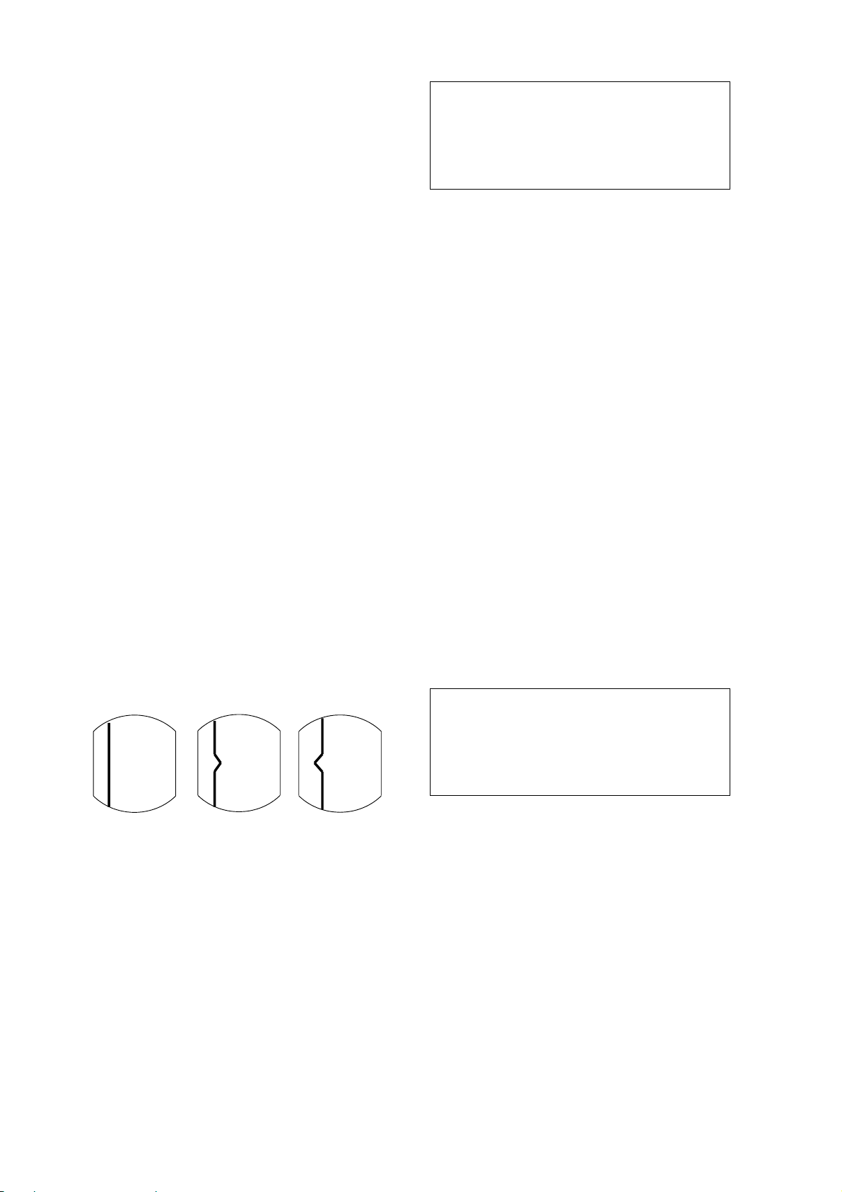
5. As a final test, move the boat towards a
small buoy and confirm that the buoy
shows up dead ahead on the radar when it
is visually dead ahead.
Adjusting sweep timing
(Adjustment range:0.000~4.266nm)
[ Sweep Timing Adjustment ]
Use omnipad to straighten
target and press ENTER key.
Correction 0.000 nm
<Press MENU for inst setup>
This adjustment ensures proper radar performance, especially on short ranges. The radar
measures the time required for a transmitted
echo to travel to the target and return to the
source. The received echo appears on the display based on this time. Thus, at the instant
the transmitter is fired, the sweep should start
from the center of the display (sometimes
called sweep origin.)
A trigger pulse generated in the display unit
goes to the antenna unit through the signal
cable to trigger the transmitter (magnetron).
The time taken by the signal to travel up to
the antenna unit varies, depending largely on
the length of signal cable. During this period
the display unit should wait before starting
the sweep. When the display unit is not adjusted correctly, the echoes from a straight
local object (for example, a harbor wall or
straight pier) will not appear with straight
edges - namely, they will be seen as “pushed
out” or “pulled in” near the picture center . The
range of objects will also be incorrectly
shown.
Figure 6-25 Sweep timing adjustment
message
4. Operate the omnipad to straighten the target selected at step 2, and then press the
[ACQ/ENTER] key.
Adjusting MBS
(Adjustment: 0.00~0.25)
Main bang (black hole), which appears at the
display center on short ranges, can be suppressed as follows.
1. Transmit on long range about 10 minutes.
2. Adjust the gain to show a small amount of
noise on the display.
3. Change to the 0.125 nautical mile range
and adjust the [A/C SEA] control.
4. Select “11. MBS adjustment” on the installation setup menu.
5. Press the [ACQ/ENTER] key . The following message appears.
[ MBS Adjustment ]
Set value by omnipad
and press ENTER key.
(1) Correct
(2) Target pushed
inward
(3) Target pushed
outward
Figure 6-24 Examples of improper and
correct sweep timing
1. Transmit on the shortest range and confirm
that the [GAIN] and [A/C SEA] controls
are properly adjusted.
2. Visually select a target which forms straight
line (harbor wall, straight pier).
3. Select “10. Sweep Timing Adjustment” on
the installation setup menu and press the
[ACQ/ENTER] key . The message appears.
34
Correction 000
<Press MENU for inst setup>
Figure 6-26 MBS Adjustment message
6. Operate the omnipad to suppress main
bang. (left: low , right: high, between 0 and
25)
7. Press the [ACQ/ENTER] key.
Page 46
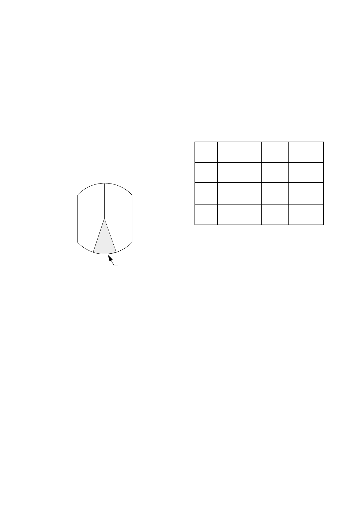
Setting a blanking area
Magnetron heater voltage
When the antenna is installed at a close distance in front of the wheelhouse, the radar
should be set not to transmit within that area.
No echoes appear in the blanking areas.
1. Select "7. Dead Sector".
2. Press the [ENTER] key.
3. Operate the omnipad to enter starting point
of area (in figures).
4. Press the [ENTER] key.
5. Operate the omnipad to enter ending point
of area (in figures).
6. Press the [ENTER] key.
Magnetron heater voltage is formed at the MD
Board of the antenna unit and preadjusted at
the factory for use with any length of signal
cable. Therefore no adjustment is required.
However, verify heater voltage by following
the procedure below.
1. Turn on the radar (if it is not already on)
and set it in stand-by.
2. Open the antenna housing (radome) cover .
Connect a multitester , set to 10 V DC range.
Model Check Point Rating Adjustment
point
M1832 TP802 #4, #6 on
PTU Board
M1932 TP803 #4, #6 on
MD Board
M1942 TP803 #4, #6 on
MD Board
7.4~7.6V R106
7.4~7.6V VR801
7.5~7.7V VR801
Area of no
transmission
Figure 6-27 Blank areas where
transmission is suspended
This area can be turned on/off on the OTHER
MENU. For detail, see the description on page
18.
Note: This setting should be done after other
adjustments are finished.
3. Close the antenna housing cover and tighten
the fixing bolts.
35
Page 47
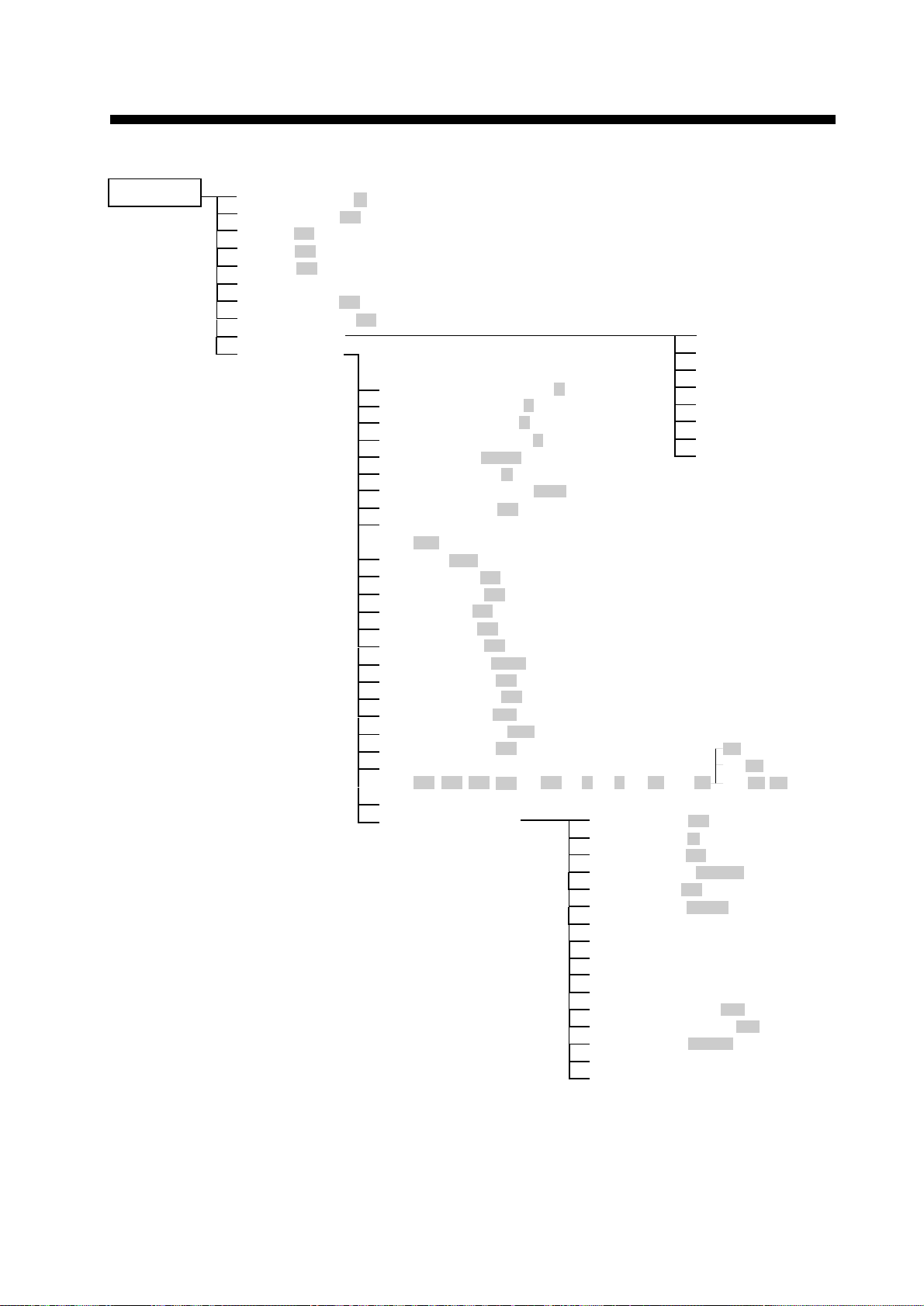
MENU TREE
RINGS (Off, 1, 2, 3, max)
EBL OFFSET (Off, On)
SHIFT (Off, On)
ZOOM (Off, On)
MODE (HU, CU, NU, TM)
DISP DATA
ECHO TRAIL (Off, On)
ECHO STRTCH (Off, ES1, ES2)
ARP-10 MENU
OTHER MENU
1.
2.
3.
4.
5.
6.
7.
8.
9.
10.
11.
12.
13.
14.
15.
16.
17.
18.
19.
20.
21.
22.
23.
24.
Panel Dimmer (1, 2, 3, 4)
Mark Brill (1, 2, 3, 4)
HD Mark (1, 2, 3, 4)
Characters (1, 2, 3, 4)
Trail Tone (Single, Multi)
Int Reject (Off, 1, 2, 3)
Pulselength (Short, Long)
Noise Reject (Off, On)
Trail Time
(15S, 30S, 1M, 3M, 6M, 15M, 30M, Cont)
Tone (Auto, Manu)
Disp Data (Off, Nav, ARP, All)
WPT Mark (Off, On)
EBL Ref (Rel, True)
VRM Unit (nm, km, sm)
Watchman (Off, 5M, 10M, 20M)
STBY DISP (Norm, Econo, Nav)
Guard Mode (In, Out)
Own Position (L/L, TD)
Cursor Posi (B/R, L/L)
Alm Sense LV (Low, Mid, High)
Dead Sector (Off, On)
Range
(1/8, 1/4, 1/2, 3/4, 1, 1.5, 2, 3, 4, 6, 8, 12, 16, 24,
Self Test
Installation Setup
1. Display
2. All Cancel
3. Vector ref
4. Vector Length
5. History
6. CPA SET
7. TCPA SET
8. AUTO ACQ
1.
2.
3.
4.
5.
6.
7.
8.
9.
10.
11.
12.
13.
14.
15.
16.
Nav Talker (All, GPS, LC)
Depth Unit (m, fa, ft)
Temp Unit (°C, °F)
Hdg Sensor (Magnet, Gyro)
Key Beep (Off, On)
Scan Stop (Rotate, Stop)
Dead Sector
Tune/Video Adjustment
Heading Alignment
Sweep Timing Adjustment
MBS Adjustment
Ant Height (Low, Mid, high)
STC Curve (Sharp, Std, Gntl)
Ope Mode (Master, Slave)
Hours in Use
TX Hours
MENU KEY
36) :1832
36, 48) :1932
36, 48, 64) :1942
AP-1
Page 48

ARP-10 (OPTION)
WARNING
Hazardous voltage can
shock, burn, or cause death.
Only qualified personnel should
work in the unit.
This auto plotter is not designed to
replace the human eye nor make
decisions for the navigator. It is
intended for use as an aid to navigation.
Always maintain a watch while
underway. Data obtained from this auto
plotter should always be double checked
against other sources to verify the
reliability of the data.
This auto plotter automatically tracks a
acquired radar target and calculates its
course and speed, indicating it by a vector.
Since the data generated by this unit are
based on what radar targets are selected,
the radar must always be optimally tuned
for use with it to ensure that required
targets will not be lost or unwanted targets
such as sea returns and noise will not be
acquired and tracked.
A target echo does not always mean a
landmass, reef, ships or other surface
objects but can imply returns from sea
surface or precipitation. As the level of
these returns varies with environment, the
operator is required to properly adjust the
STC (ant-clutter sea), FTC (anti-clutter rain)
and GAIN controls to ensure that target
echoes within the affected area are not
eliminated from the radar screen. The
optimum settings of these controls may
slightly differ between the normal radar
operation and plotting, and it is
recommended to readjust them in
accordance with the operating mode
selected.
NOTICE
The installation must be done by a
FURUNO representative or suitably
qualified radar technician.
Authorities require this.
Keep magnets and magnetic fields
away from the equipment.
Magnetic fields will distort the picture and
can cause equipment malfunction. Be sure
the unit is well away from equipment
which gives off magnetic fields
(speaker, power transformer, etc.).
The following items affect calculation
accuracy.
• echo intensity
• radar transmission pulsewidth
• radar bearing error
• gyrocompass error
• own vessel or other vessel course
change
Data for CPA, TCPA, etc. are
approximations only. Always use data
obtained prudently.
AP-2
Page 49

Operation of ARP-10
General
The Auto Plotter ARP-10 is an optional circuit board which is accommodated in the display unit of the MODEL 1832, 1932 and 1942
radars.
The Auto Plotter permits manual or automatic
acquisition and automatic tracking of up to
10 radar targets. An internal microprocessor
calculates target data such as speeds and
courses and displays the results in alphanumeric and by vectors. To ensure the reliability of the displayed target data, the radar must
be properly adjusted for minimum sea returns
and noise.
Principal Specifications
Keys Used for Auto Plotter
The Auto plotter utilizes the following
touchpad keys. Given below is a brief description of these keys.
MENU: Displays/Erases the main menu.
SELECT/CANCEL:
(Long press) T erminates plotting of the tar get
selected with the cursor.
(Brief press) Displays the data of target selected with the cursor.
ACQ/ENTER: Acquires the target selected
with the cursor.
ARP-10 MENU Operation
The ARP-10 MENU operation includes the
followings;
Acquisition and tracking:
• Acquisition of up to 10 targets between 0.2
and 16 nm.
• Automatic tracking of up to 10 acquired
targets between 0.1 and 16 nm.
Vectors:
Vector length; 30 s, 1, 3, 6, 15, 30 min.
Orientation; True velocity or relative
velocity
Past positions: 5 past positions at intervals
of 15, 30 s, 1, 2, 3, 6 min.
Alarm: Visual and audible alarms against
targets violating CPA/TCPA
limits, Visual alarm against lost
targets
Target discrimination: A target measuring
about 800 m or more in the radial or circumferential direction is regarded as a landmass
and not acquired or tracked. Echoes smaller
than about 800 m are regarded as true targets.
Display: Turns on/off the plot symbols, past
positions and target data.
All Cancel: Cancels the tracking of all
targets.
Vector Ref: Selects relative vector or
true vectors. To select your choice, open the
ARP-10 menu, and the legend Rel and True
appear on the "3. Vector Ref" line. Operate
the omnipad. When your selection is in the
reverse video, press the [ACQ/ENTER] key.
Vector Length: Selects vector time.
History: Selects past position plot interval.
CPA Set: Selects CPA alarm limit. When a
target is predicted to come within this limit,
an aural alarm sounds and at the same time
the corresponding target symbol changes to a
blinking triangle.
Note:If the preset CPA limit is set at OFF, a
target which is on collision course will not
produce an alarm.
TCPA Set: Selects TCPA alarm limit.
Auto ACQ: Turns on/off Auto Acquisition
Area.
AP-3
Page 50

Activating the Auto plotter
To activate the Auto Plotter, follow the steps
shown below:
1. Adjust the GAIN, A/C SEA and A/C RAIN
controls for proper radar picture.
2. Press the [MENU] key to open the main
menu.
3. Operate the omnipad to select "ARP-10
MENU".
4. Press the [ACQ/ENTER] key. The menu
shown in Figure AP-1 appears.
[ ARP MENU ]
Select item by omnipad
and press ENTER key.
¡. Display
2 . All Cancel
3 . Vector Ref
4 . Vector Length
5 . History
6 . CPA Set
7 . TCPA Set
8 . Auto ACQ
Off
Rel
3M 6M
Off 15S
2M 3M Off
Off 0.5
3nm 5nm
30S 1M
4M 5M
Off
On
True
30S
15M
30SLo
6M
1nm
6nm
2M
6M
On
1M
30M
1M
2nm
3M
12M
Figure AP-1 ARP Menu
5. Operate the omnipad to select the menu
item "1. Display".
6. Operate the omnipad to select "On".
7. Press the [ACQ/ENTER] key.
Target Full
Mark
Lost Target
8. Press the [MENU] key to close the menu.
Target under auto tracking but not
selected for cursor data reading
AUTO
8
NM
AUTO TARGET
2
FULL
SP
HU
HDG 234.5°
TRAIL
25:38
30M
G (OUT)
ZOOM
ES1
Target selected
for data reading
Auto
Acquisition
Area
Threatening
target
AP-4
A/C
AUTO
EBL
345.6 R
°
23.0 R
°
TRUE VECTOR
15 MIN
VRM
13.5 R°
BEARING 42.5°T
RANGE 5.36 NM
CPA 2 NM
0.142NM
0.048NM
0.100NM
COURSE 287.8°T
SPEED 12.5 KT
TCPA 12:35
Figure AP-2 ARP Display
ARP Data Area
Page 51
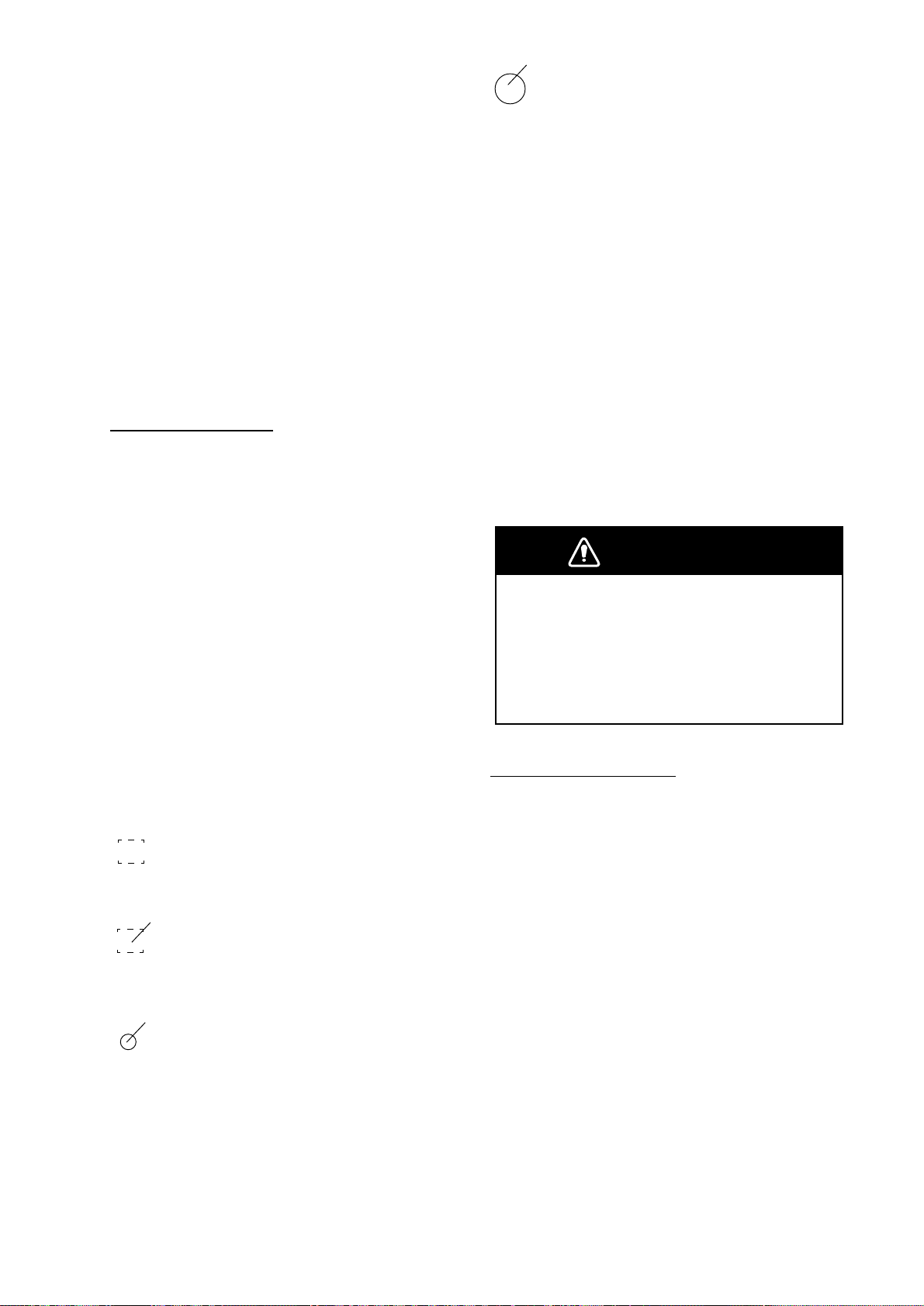
Deactivating the Auto Plotter
LARGE CIRCLE
To deactivate the Auto Plotter,
1. Open the "ARP-10 MENU".
2. Operate the omnipad to select the "1. Display".
5. Operate the omnipad to select "Off".
6. Press the [ACQ/ENTER] key.
7. Press the [MENU] key to close the menu.
Acquiring targets
Manual Acquisition
Follow the steps below to manually acquire a
target. Up to 10 targets can be manually acquired.
1. Place the cursor (+) on a target of interest
by operating the omnipad.
The plot symbol of a target under tracking
becomes twice as large as the normal symbol
when the target is selected for data reading.
Note 1:The target to be acquired should be
within 0.2 to 16 nm from own ship and not
obscured by sea or rain clutter for successful
acquisition.
Note 2:When you want to acquire 11th tar get,
cancel tracking one of less important targets.
Note 3:When auto acquisition mode (Auto
ACQ) is on, up to 5 targets can be acquired.
For detail, see next section titled Automatic
Acquisition.
WARNING
2. Press the [ACQ/ENTER] key.
The plot symbol changes its shape according
to the status as below. A vector appears in
about one minute after acquisition indicating
the target's motion trend. If the target is consistently detected for three minutes, the plot
symbol changes to a solid mark. If acquisition fails, the target symbol blinks and disappears shortly.
SQUARE (dotted)
Immediately after acquisition - Plot symbol
shown in broken lines.
SQUARE (dotted with a vector)
One minute after acquisition - Vector still unreliable.
CIRCLE (Solid with a vector)
3 minutes after acquisition - Plot symbol
changes to a solid circle indicating the stable
tracking condition.
When a tracked target nears another
tracked target, the targets may be
"swapped." When two targets come close
to each other, one of the two can become
a "lost target." Should this happen,
reacquisition of the "lost target" is required
after the two targets have separated.
Automatic Acquisition
The Auto plotter ARP-10 can acquire up to 5
targets automatically by setting the Auto Acquisition area predefined in the system. If Auto
ACQ is selected after more than 5 targets have
been manually acquired, only the remaining
capacity of targets can be automatically acquired. Example; when 7 targets acquired
manually, then the Auto ACQ is switched on
only 3 targets can be acquire automatically.
When five targets have been automatically
acquired, "AUTO TARGET FULL" message
appears at top left corner on the display.
Setting Auto Acquisition Area
Auto acquisition area is predefined between
2.0 and 2.5 nm in range and 45º on either side
of the heading line in bearing. If a target come
into this area, it is acquired automatically.
AP-5
Page 52

Figure AP-4 Auto acquisition area
Follow the steps shown below to activate the
auto acquisition area;
1. Open the "ARP-10 MENU".
To turn ARP data on;
1. Press the [MENU] key.
2. Select the "DISP DATA".
3. Press the [ACQ/ENTER] key to select the
message for "ARP" or "NAV and ARP ".
4. Press the [ACQ/ENTER] key to set.
5. Press the [MENU] key to close the menu.
2. Select "8. Auto ACQ" by operating the
omnipad.
3. Operate the omnipad to select "On".
4. Press the [ACQ/ENTER] key.
5. Press the [MENU] key to close the menu.
Terminating Tracking of Targets
When the Auto Plotter has acquired 10 targets, no more acquisition occurs unless targets are lost. Should this happen, cancel
tracking of individual targets or all targets by
the procedure described below.
Individual Targets
Place the cursor (+) on a target which you do
not want to be tracked any longer by operating the omnipad and press and hold down the
[SELECT/CANCEL] key.
CAUTION
At the speed under 5 kts the target data is
displayed with a delay because of
filtration.
Place the cursor on a wanted target and press
the [SELECT/CANCEL] key . Data on the selected target is displayed at the bottom of the
screen. The symbol of the selected target gets
twice as large as the normal circle. The data
includes the follows;
RNG/BRG (Range/Bearing): Range and
bearing from own ship to the last-plotted or
selected target position with suffix "T" (T rue)
or "M" (Magnetic). For true bearings suffix
"T" is used in case of gyrocompass input and
suffix "M" is used in case of magnetic compass input.
All Targets
All targets can be canceled from "ARP-10
MENU" at a time.
1. Open the "ARP-10 MENU".
2. Select "2. All Cancel".
3. Press the [ACQ/ENTER] key.
Displaying Target Data
The Auto Plotter calculates motion trends
(range, bearing, course, speed, CPA and
TCP A) of all targets under tracking at the ARP
Data area.
AP-6
COURSE/SPEED (Course/Speed):
Course and speed are displayed for the lastplotted or selected target with suffix "T" (T rue)
or "M" (Magnetic). For true bearings suffix
"T" is used in case of gyrocompass input and
suffix "M" is used in case of magnetic compass input.
CPA (Closest Point of Approach) is the closest range a target will approach to own ship.
Do not mix it with the operator preset CPA
alarm limit.
Page 53
TCPA is the time to CPA measured with
present speeds of own ship and the targets.
Both CPA and TCPA are automatically calculated. When a target ship has passed clear
of own ship, the CPA is displayed and the
TCP A appears as "**.*". TCP A is counted up
to 99.9 min. and beyond this it is indicated as
TCPA>99.9 min.
Mode and length of Vectors
CPA/TCPA Alarm
V isual and audible alarm are generated when
the predicted CPA and TCPA of any target
become less than their preset limits. The audible alarm continues for 10 seconds.
The Auto plotter ARP-10 continuously monitors the predicted range at the Closest Point
of Approach (CP A) and predicted time to CP A
(TCPA) of each tracked target to own ship.
True or Relative Vector
T arget vectors are displayed in relative or true
mode. Own ship does not have a vector in relative mode.
Vector Length
From the ARP-10 MENU, Vector Length can
be set to 30 seconds, 1, 3, 6, 15 or 30 minutes
and the selected vector time is indicated on
the screen.
The vector tip shows an estimated position of
the target after the selected vector time
elapses. It can be valuable to extend the vector length to evaluate the risk of collision with
any target.
Past position Display
When the predicted CPA of any target becomes smaller than a preset CPA alarm range
and its predicted TCPA less than a preset
TCPA alarm limit, the ARP-10 releases an
audible alarm. In addition, the target plot symbol changes to a triangle and flashes together
with its vector.
Provided that this feature is used correctly, it
will help prevent the risk of collision by alerting you to threatening targets. It is important
that GAIN, A/C SEA, A/C RAIN and other
radar controls are properly adjusted and the
Auto Plotter is set up so that it can track targets effectively.
CP A/TCP A alarm ranges must be set up properly taking into consideration the size, tonnage, speed, turning performance and other
characteristics of own ship.
The Auto Plotter displays equally time-spaced
dots (maximum 5 dots) marking the past positions of any targets being tracked.
If a target changes its speed, the spacing will
be uneven. If it changes the course, its plotted
course will not be a straight line in TM mode.
Operational Warnings
There are two main situations which cause the
Auto plotter to trigger visual and audible
alarms.
• CPA/TCPA alarm
• Lost target alarm
WARNING
The CPA/TCPA alarm feature should
never be relied upon as a sole means for
detecting the risk of collision.
The navigator is not relieved of the
responsibility to keep visual lookout for
avoiding collisions, whether or not the
radar or other plotting aid is in use.
Follow the steps shown below to set the CP A/
TCPA alarm ranges:
1. Open the "ARP-10 MENU".
2. On the "CPA Set" line, select a CPA limit
desired. (Off, 0.5, 1, 2, 3, 5, 6 nm)
3. Press the [ACQ/ENTER] key.
AP-7
Page 54
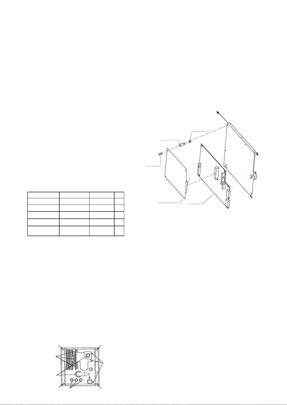
4. On the "TCP A Set" line, select a TCP A limit
desired. (30s, 1, 2, 3, 4, 5, 6, 12M)
5. Press the [ACQ/ENTER] key.
6. Press the [MENU] key to close the menu.
The flashing of the triangle plot symbol and
vector remain on the screen until the dangerous situation is no longer present or you intentionally terminate tracking of the target by
using the [SELECT/CANCEL] key.
Lost Target Alarm
When the system detects a loss of a tracked
target, the target symbol becomes a flashing
diamond.
2. Attach the ARP-10 Board to the right-hand
chassis of the display unit, using the spacer
supplied as follows.
1) Fasten three spacers tightly.
2) Attach the P107 connector on ARP10 Board to J107 connector on
SPU Board.
3) Tighten three pan head screws to fix the
ARP-10 Board.
Front
Spring Washer
M3 3pcs.
Spacer
SQ-20 3pcs.
$
Installation of ARP-10
Necessary Parts
ARP-10 (000-086-852)
emaNepyT.oNedoCytQ
draoB01-PRA
recapS
rehsaWgnirpS
wercSdaeHnaP
wercSdaeHnaP
*)rehsaw/w(
* Not used.
Mounting (For technician only)
1. Remove the cover from the display unit as
follows.
1 Unscrew four binding screws (M4 x
10).
2 Unfasten six binding screws (M3 x
10).
3 Remove three rubber covers to loosen
three hex nuts.
7009P81039-674-800
02-QS056-108-000
W1915C3M402-468-000
W0072C8x3M404-188-000
01MRWS8x3477-508-0003
1
3
3
3
$
Pan Head
Screw
M3 x 8 3pcs.
P107
ARP-10 Board
18P9007
$: Pull the front panel slightly to fix these screws.
SPU Board
SPU9211
J107
Input Signal Check
Place the radar in transmit condition after connecting the speed and heading sensor. Make
sure the following items are OK on Self Test
menu.
• SPEED
• COURSE
• TRIGGER
Video Signal Check
Make sure the follows on Self Test menu.
4 Loosen two hex nuts.
1
2
4
AP-8
1
3
• VIDEO : OK
1
• Adjust GAIN, A/C SEA and A/C RAIN so
that the readout for FE-DATA 1 and 2 are
less than 1,000.
2
1
Page 55
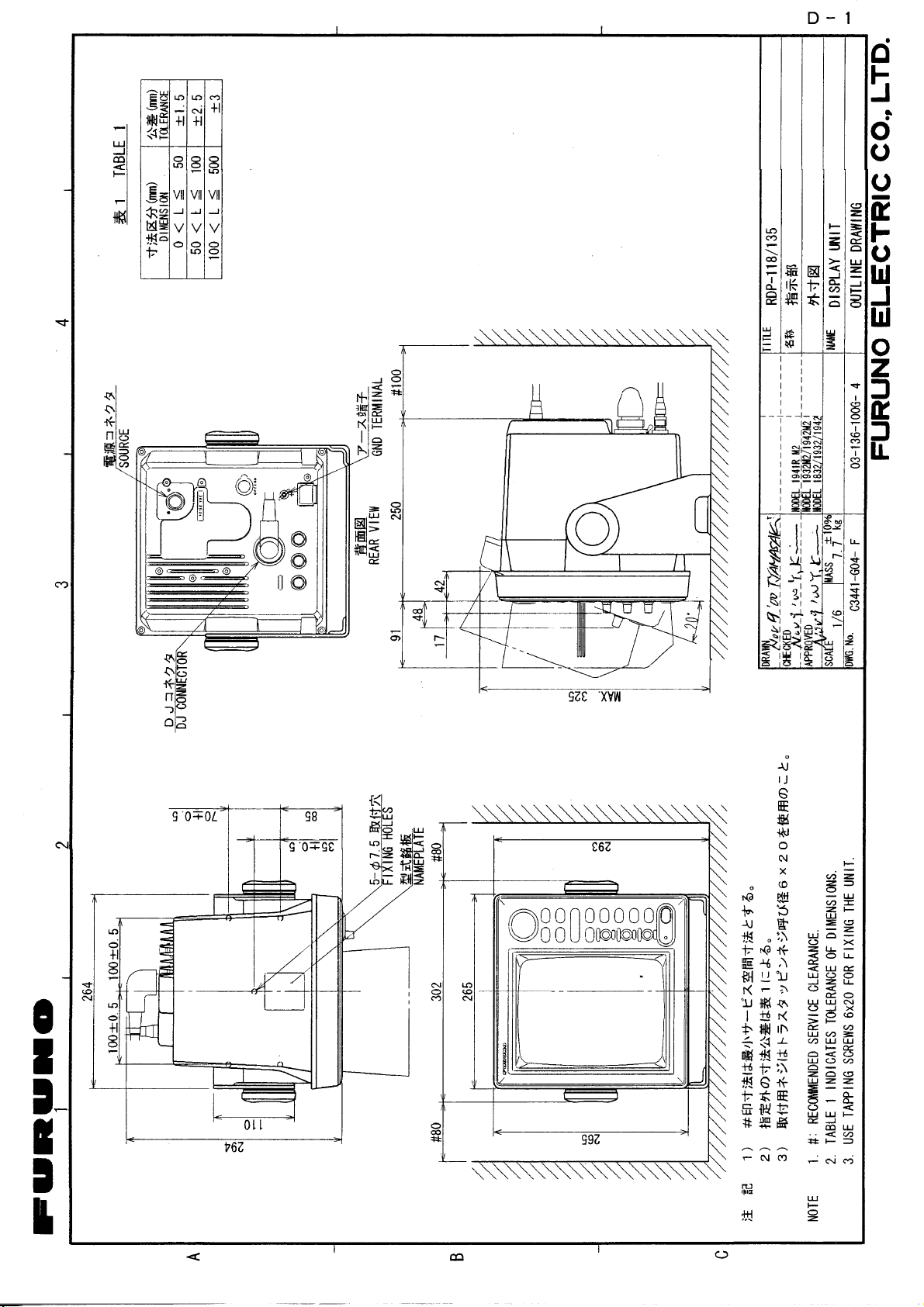
Page 56
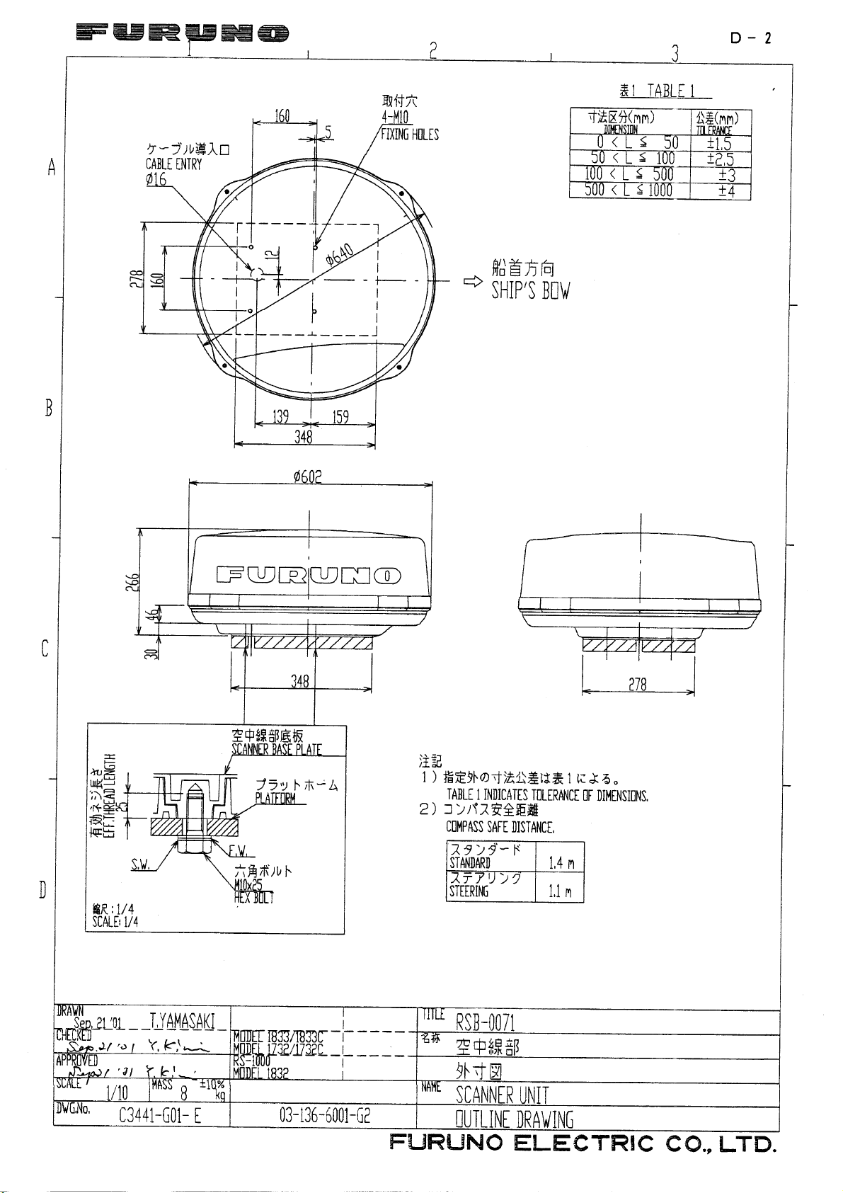
Page 57
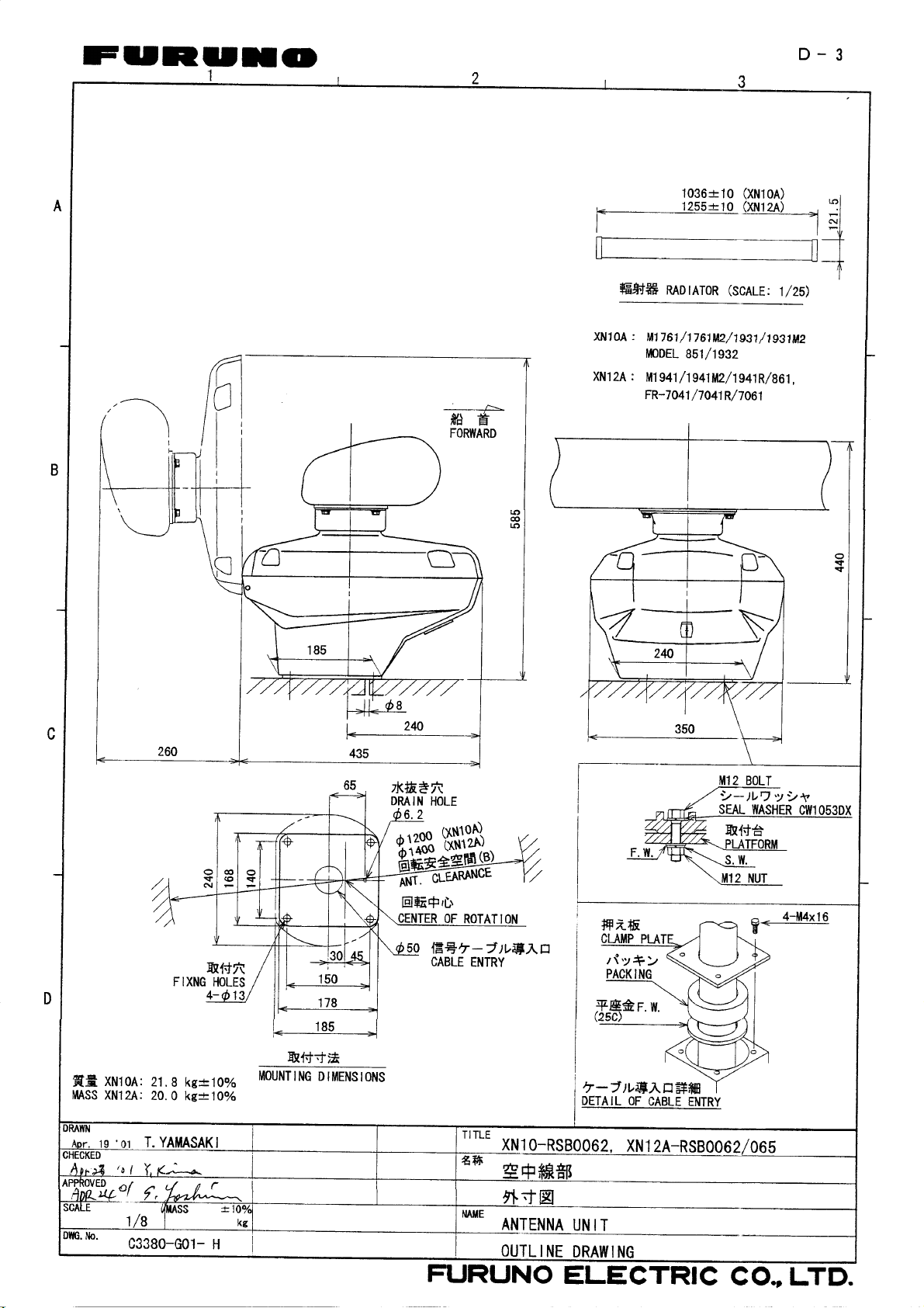
Page 58
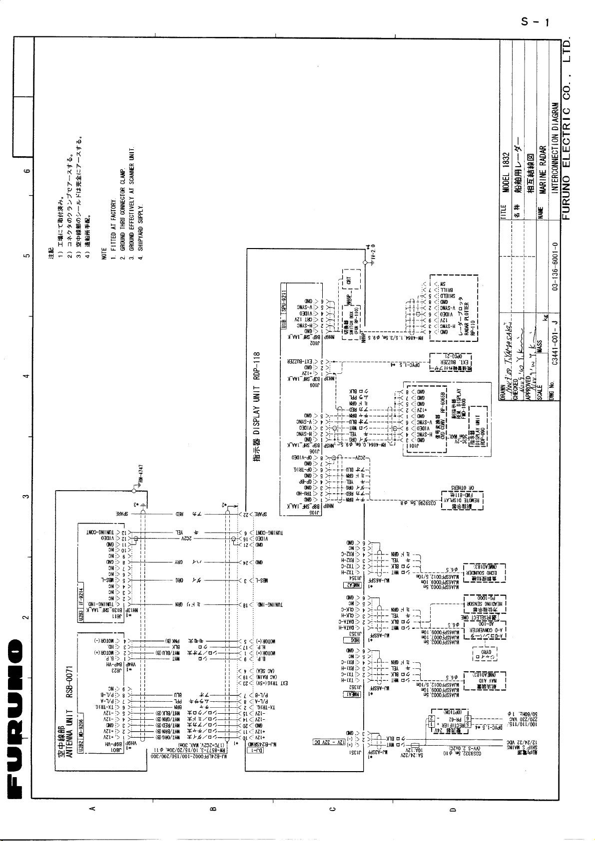
Page 59
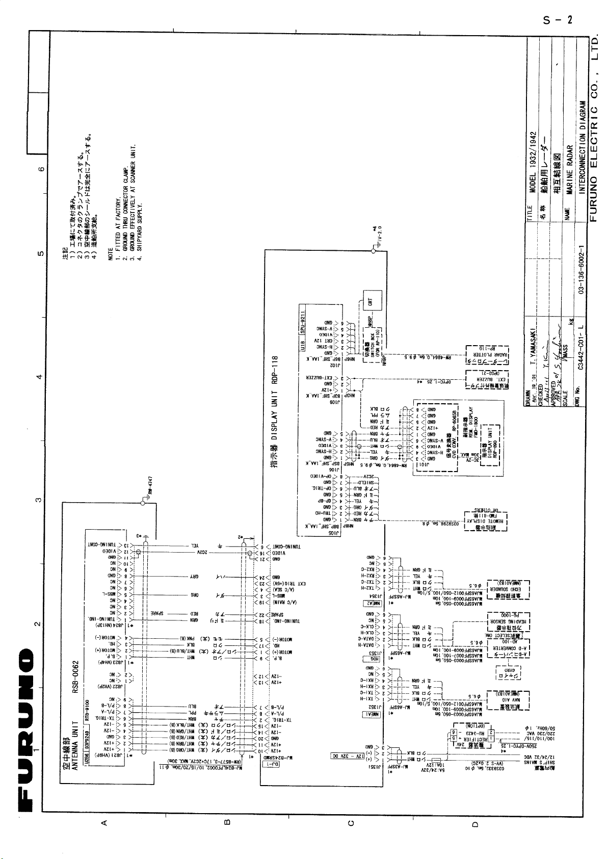
Page 60
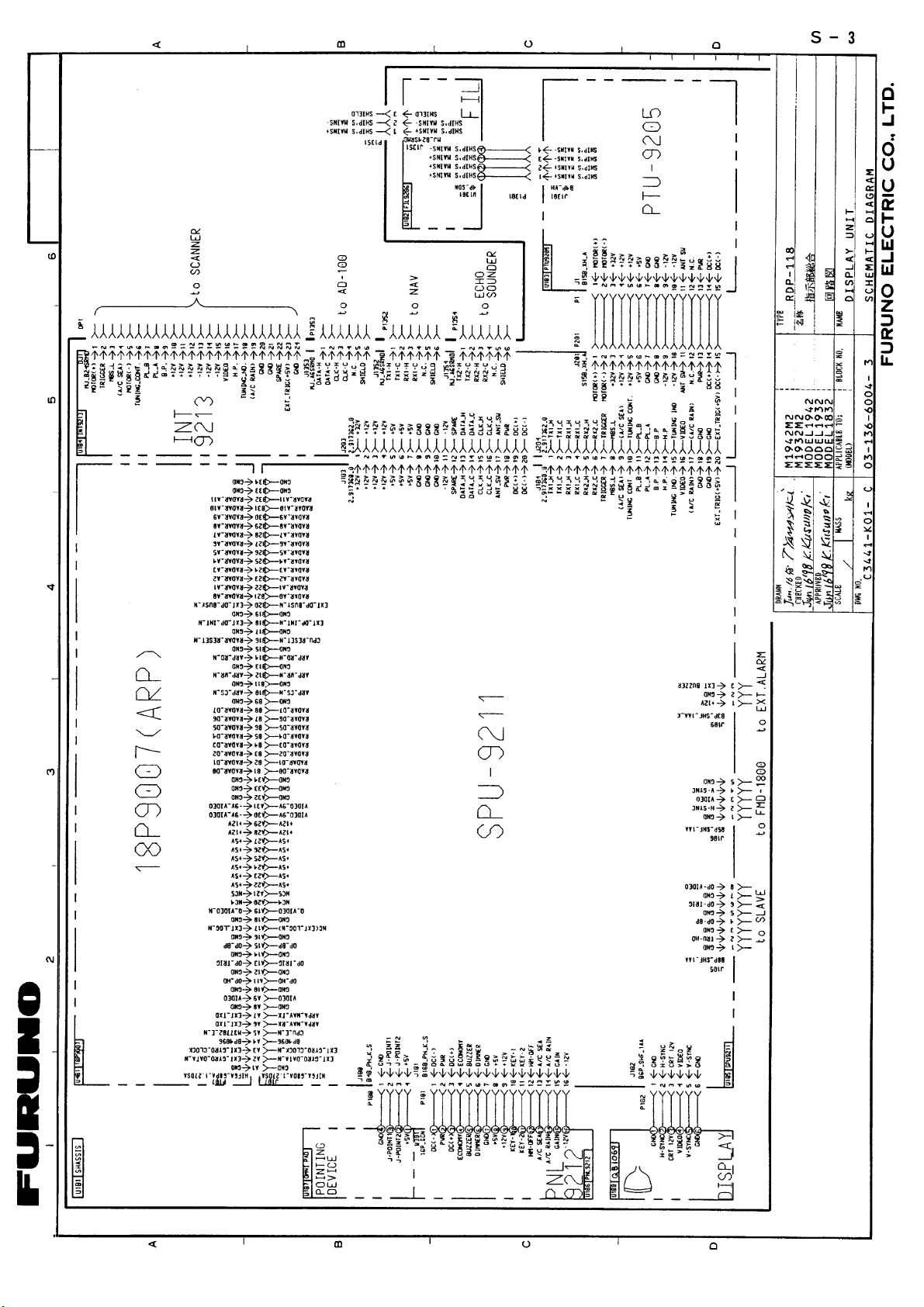
Page 61
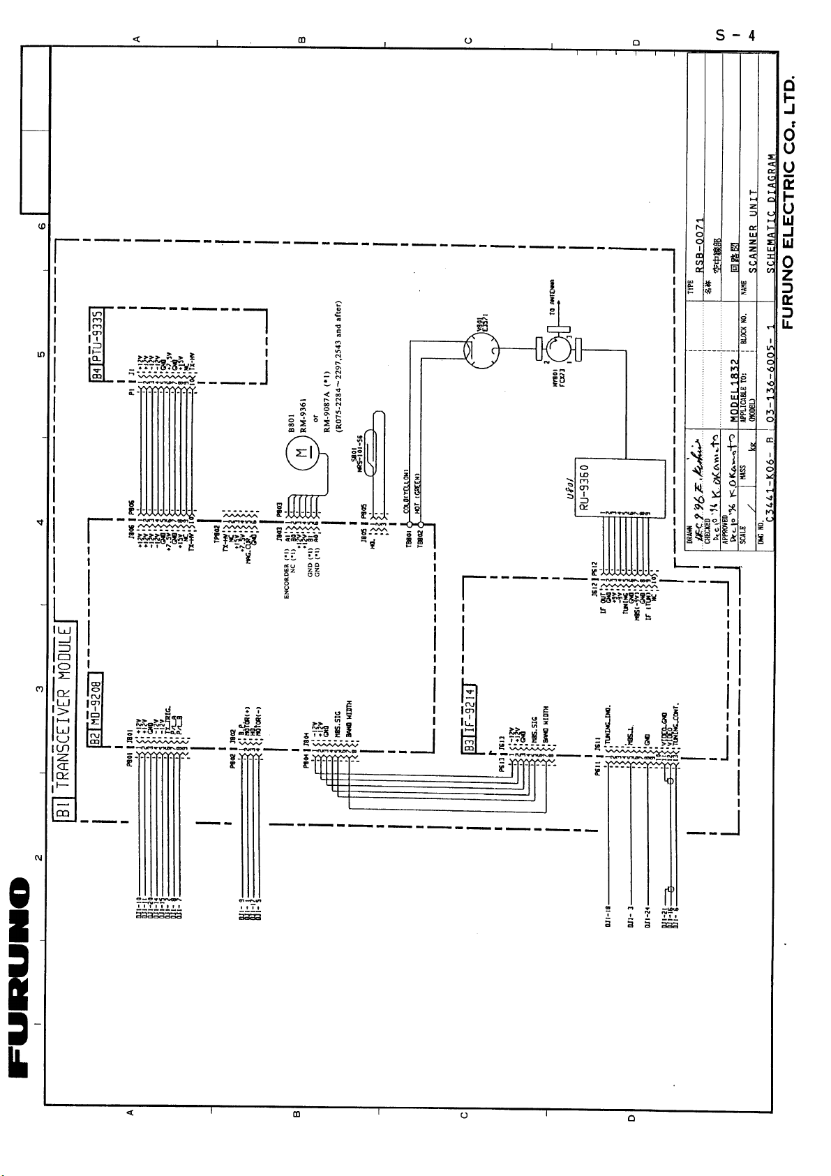
Page 62
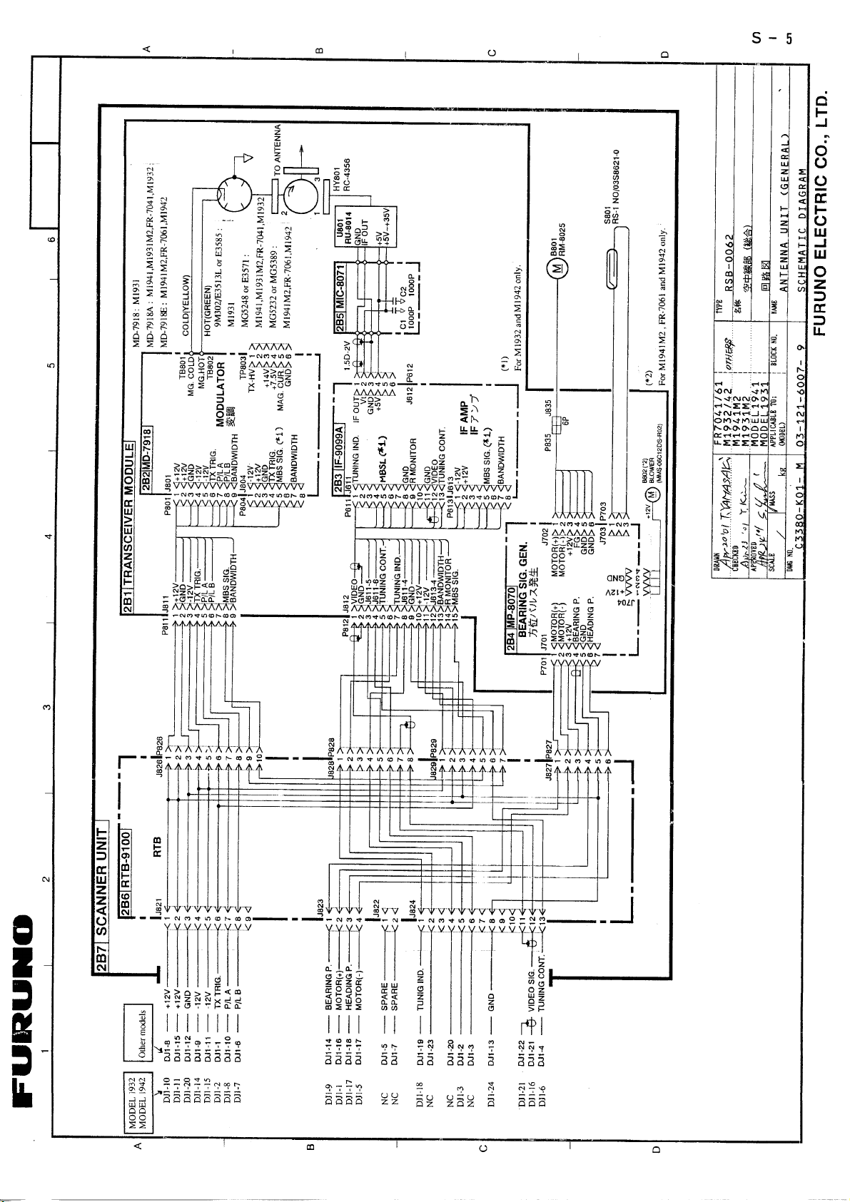
Page 63
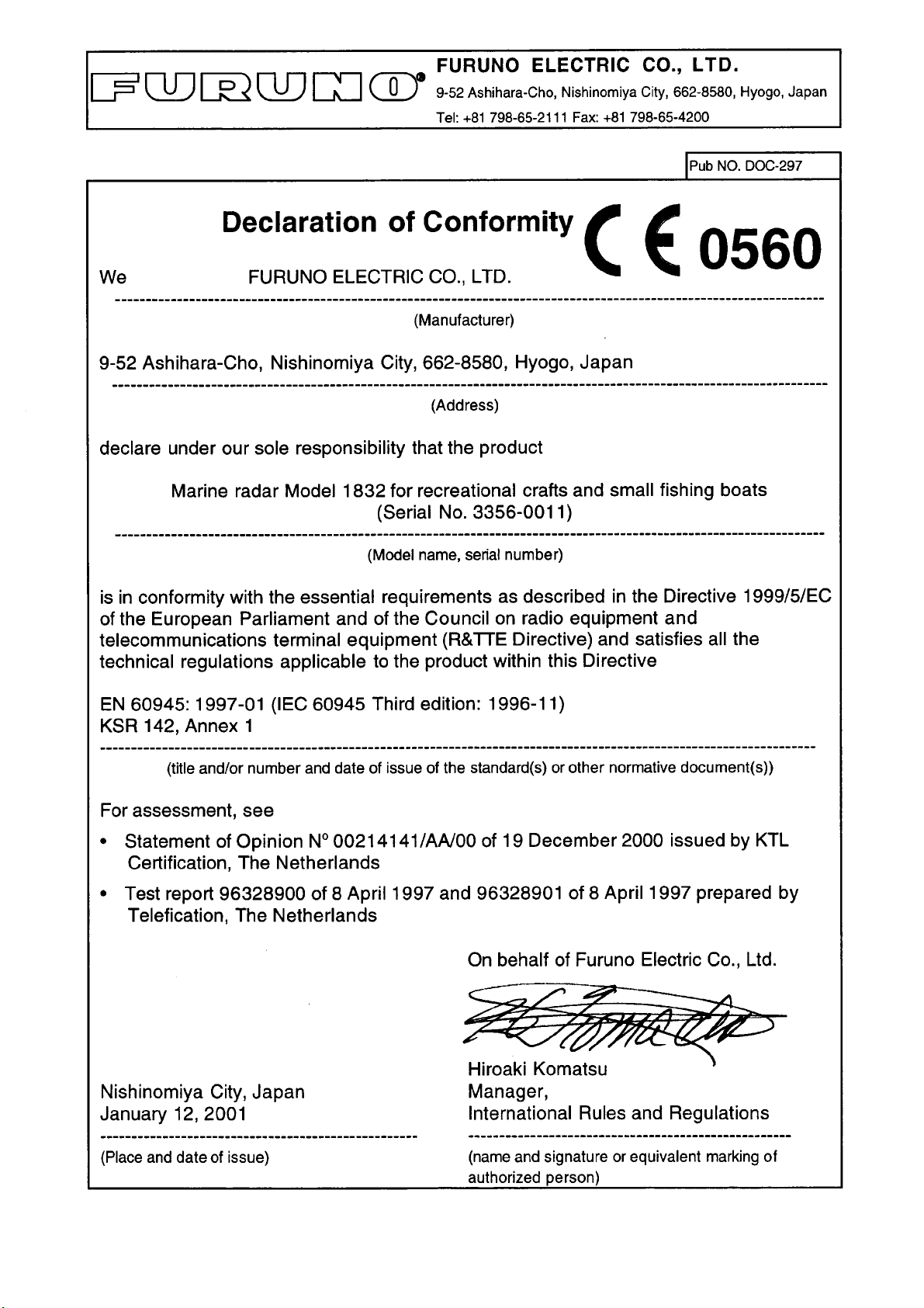
 Loading...