

Furuno 1815 Operator's Manual

OPERATOR'S MANUAL
MARINE RADAR
MODEL 1815
www.furuno.com

The paper used in this manual
9-52 Ashihara-cho,
A:FEB
2017
.
A1:MAR.10, 2017
Pub. No.
(
)
Nishinomiya, 662-8580, JAPAN
is elemental chlorine free.
・FURUNO Authorized Distributor/Dealer
All rights reserved.
DAMI
MODEL1815
Printed in Japan
OME-36660-A1
0 0 0 1 9 2 8 5 4 1 0

IMPORTANT NOTICES
Cd
Ni-Cd Pb
General
• This manual has been authored with simplified grammar, to meet the needs of international users.
• The operator of this equipment must read and follow the descriptions in this manual.
Wrong operation or maintenance can cancel the warranty or cause injury.
• Do not copy any part of this manual without written permission from FURUNO.
• If this manual is lost or worn, contact your dealer about replacement.
• The contents of this manual and equipment specifications can change without notice.
• The example screens (or illustrations) shown in this manual can be different from the screens you
see on your display. The screens you see depend on your system configuration and equipment
settings.
• Save this manual for future reference.
• Any modification of the equipment (including software) by persons not authorized by FURUNO will
cancel the warranty.
• The following concern acts as our importer in Europe, as defined in DECISION No 768/2008/EC.
- Name: FURUNO EUROPE B.V.
- Address: Ridderhaven 19B, 2984 BT Ridderkerk, The Netherlands
• All brand and product names are trademarks, registered trademarks or service marks of their
respective holders.
How to discard this product
Discard this product according to local regulations for the disposal of industrial waste. For disposal in
the USA, see the homepage of the Electronics Industries Alliance (http://www.eiae.org/) for the
correct method of disposal.
How to discard a used battery
Some FURUNO products have a battery(ies). To see if your product has a battery, see the chapter on Maintenance. Follow the instructions below if a battery is used. Tape the + and - terminals
of battery before disposal to prevent fire, heat generation caused by short circuit.
In the European Union
The crossed-out trash can symbol indicates that all types of batteries must
not be discarded in standard trash, or at a trash site. Take the used batteries to a battery collection site according to your national legislation and the
Batteries Directive 2006/66/EU.
In the USA
The Mobius loop symbol (three chasing arrows) indicates that
Ni-Cd and lead-acid rechargeable batteries must be recycled.
Take the used batteries to a battery collection site according to
local laws.
In the other countries
There are no international standards for the battery recycle symbol. The number of symbols can
increase when the other countries make their own recycle symbols in the future.
i
SAFETY INSTRUCTIONS
WARNING
Indicates a condition that can cause death or serious
injury if not avoided.
CAUTION
Indicates a condition that can cause minor or moderate
injury if not avoided.
Warning, Caution
Mandatory Action
Prohibitive Action
Read these safety instructions before you operate or install the equipment.
WARNING
Radio Frequency Radiation Hazard
The radar antenna sends the electromagnetic
radio frequency (RF) energy. This energy can
be dangerous to you, especially your eyes.
Do not look at the radiator or near the
antenna when the antenna is rotating.
The distances at which RF radiation levels of
100 W/m
2
, 50 W/m2 and 10 W/m2 exist are
shown in the table.
Note: If the antenna unit is installed at a
close distance in front of the wheel house,
prevent the transmission in that area to
protect passengers and crew from microwave
radiation. Set the [Sector Blanks] in the
[System] menu.
Distance to
100 W/m
2
point
Distance to
50 W/m
2
point
Distance to
10 W/m
2
point
Worst case 85 cm
Standard Steering
Display unit
0.45 m
0.30 m
CAUTIONCAUTION
Antenna unit
1.70 m
1.05 m
Unit
Observe the following compass safe distances to
prevent deviation of a magnetic compass.
WARNING
Do not open the equipment.
The equipment uses high voltage that
can cause electrical shock. Refer any
repair work to a qualified technician.
Before turning on the radar, be sure
no one is near the antenna.
Prevent the potential risk of being
struck by the rotating antenna, which
can result in serious injury or death.
If water leaks into the equipment or
something is dropped into the
equipment, immediately turn off the
power at the switchboard.
Fire or electrical shock can result.
If the equipment is giving off smoke
or fire, immediately turn off the
power at the switchboard.
Fire or electrical shock can result.
Do not disassemble or modify the
equipment.
Fire, electrical shock or serious injury
can result.
Do not place operate the equipment
with wet hands.
Electrical shock can result.
ii
SAFETY INSTRUCTIONS
CAUTION
CAUTION
WARNING
Usethe correct fuse.
Use of a wrong fuse can result in fire or
damage to the equipment.
Do not place liquid-filled containers
on the equipment.
Fire or electrical shock can result if a
liquid spills into the equipment.
Target Tracking (TT) safety information
WARNING
The TT function is a valuable aid to
navigation. However, the navigator
must check all aids available to avoid
collision.
- The TT automatically tracks an
automatically or manually acquired
radar target and calculates its course
and speed, indicating them with a
vector. Since the data generated by
the TT depends on the selected radar
targets, the radar must be optimally
tuned for use with the TT, to ensure
required targets will not be lost or
unnecessary targets, like sea returns
and noise, will not be acquired and
tracked.
- A target is not always a landmass,
reef, ship, but can also be returns
from the sea surface and from clutter.
As the level of clutter changes with
the environment, the operator must
correctly adjust the sea and rain
clutter controls and the gain control so
that the target echoes do not dis-
appear from the radar screen.
CAUTION
The guard zone alarm is an effective aid
to anti-collison.
Its use does not relieve the operator of the
responsibility to keep a vigilant watch on
his or her surroundings.
The data presented by this equipment
is intended as a source of navigation
information.
The prudent navigator never relies
exclusively on any one source of
navigation information, for safety of
vessel and crew.
CAUTIO
The plotting accuracy and response of
this TT meets IMO standards. Tracking
accuracy is affected by the following:
•
Tracking accuracy is affected by course
change. One to two minutes is required to
restore vectors to full accuracy after an
abrupt course change. (The actual amount
depends on gyrocompass specifications.)
•
The amount of tracking delay is inversely
proportional to the relative speed of the
target. Delay is approx. 15-30 seconds for
the higher relative speed; approx. 30-60
seconds for the lower relative speed. The
following factors can affect accuracy:
- Echo intensity
- Radar transmission pulse length
- Radar bearing error
- Heading sensor error
- Course change (own ship and targets)
iii

SAFETY INSTRUCTIONS
WARNING
Radiation hazard. Only qualified
personnel should work inside scanner.
Confirm that TX has stopped before
opening scanner.
Name: Warning Sticker
Type: 0
3-129-1001-3
Code No.:
100-236-743-10
Warning Label(s)
Warning label(s) is(are) attached to the
equipment. Do not remove the label(s). If a
label is missing or damaged, contact a
FURUNO agent or dealer about replacement.
TFT display
The high quality TFT (Thin Film Transistor) LCD
displays 99.99% of its picture elements. The
remaining 0.01% may drop out or light. However,
this is an inherent property of the TFT; it is not a
sign of malfunction.
iv

TABLE OF CONTENTS
FOREWORD................................................................................................................... ix
SYSTEM CONFIGURATION ..........................................................................................xi
1. INSTALLATION .....................................................................................................1-1
1.1 Equipment List............................................................................................................1-1
1.2 How to Install the Equipment......................................................................................1-1
1.2.1 Display unit.....................................................................................................1-1
1.2.2 Antenna unit ...................................................................................................1-4
1.3 Wiring .........................................................................................................................1-9
1.4 Input Signal...............................................................................................................1-11
1.4.1 Talker ...........................................................................................................1-11
1.4.2 NMEA I/O sentences....................................................................................1-11
1.5 Initial Settings ...........................................................................................................1-13
1.5.1 How to select language................................................................................1-13
1.5.2 How to select radar application ....................................................................1-15
1.5.3 Initial settings................................................................................................1-15
1.6 Optional Equipment..................................................................................................1-18
1.6.1 External buzzer ............................................................................................1-18
2. OPERATION ..........................................................................................................2-1
2.1 Controls ......................................................................................................................2-1
2.2 How to Turn the Radar On/Off....................................................................................2-2
2.3 TX/Standby.................................................................................................................2-2
2.4 Display Indications......................................................................................................2-3
2.5 How to Adjust Display Brilliance, Panel Dimmer ........................................................2-4
2.6 Menu Description........................................................................................................2-4
2.7 Tuning.........................................................................................................................2-6
2.8 Display Modes............................................................................................................2-7
2.8.1 How to select the display mode......................................................................2-7
2.8.2 Description of display modes .........................................................................2-8
2.9 How to Select the Range Scale................................................................................2-10
2.10 How to Adjust the Gain (sensitivity)..........................................................................2-10
2.11 How to Reduce the Sea Clutter................................................................................2-11
2.12 How to Reduce the Rain Clutter...............................................................................2-12
2.13 Cursor.......................................................................................................................2-13
2.14 How to Temporarily Erase the Heading Line............................................................2-14
2.15 Interference Rejector................................................................................................2-14
2.16 Noise Rejector..........................................................................................................2-15
2.17 How to Measure the Range to a Target ...................................................................2-15
2.17.1 How to adjust range ring brilliance ...............................................................2-15
2.17.2 How to measure the range with a VRM........................................................2-16
2.17.3 How to select VRM unit ................................................................................2-17
2.18 How to Measure the Bearing to a Target..................................................................2-17
2.18.1 How to measure the bearing with an EBL ....................................................2-17
2.18.2 EBL reference ..............................................................................................2-18
2.19 How to Measure the Range and Bearing Between Two Targets .............................2-19
2.20 Target Alarm.............................................................................................................2-20
2.20.1 How to set a target alarm zone ....................................................................2-20
2.20.2 How to stop the audio alarm.........................................................................2-21
2.20.3 How to select the alarm type ........................................................................2-21
2.20.4 How to sleep a target alarm temporarily.......................................................2-22
2.20.5 How to deactivate a target alarm..................................................................2-22
v

TABLE OF CONTENTS
2.20.6 How to select the target strength which triggers a target alarm................... 2-22
2.20.7 How to turn the buzzer on/off....................................................................... 2-22
2.21 How to Off-center the Display ..................................................................................2-23
2.21.1 How to select the off-center mode ...............................................................2-23
2.21.2 How to off-center the display........................................................................2-23
2.22 Zoom ........................................................................................................................2-24
2.22.1 Zoom reference............................................................................................ 2-24
2.22.2 How to zoom ................................................................................................2-25
2.23 Echo Stretch.............................................................................................................2-27
2.24 Target Trails .............................................................................................................2-27
2.24.1 Trail time ......................................................................................................2-27
2.24.2 Trail mode ....................................................................................................2-28
2.24.3 Trail gradation ..............................................................................................2-29
2.24.4 Trail color .....................................................................................................2-29
2.24.5 Trail level...................................................................................................... 2-29
2.24.6 How to restart, stop the trails .......................................................................2-29
2.24.7 Narrow trails ................................................................................................. 2-30
2.24.8 Own ship trail ...............................................................................................2-30
2.24.9 How to erase all trails................................................................................... 2-31
2.25 How to Program the FUNC Key............................................................................... 2-31
2.26 Echo Average...........................................................................................................2-32
2.27 Wiper........................................................................................................................ 2-32
2.28 Display-Curve...........................................................................................................2-33
2.29 Own Ship and Barge Mark....................................................................................... 2-33
2.29.1 How to show the own ship mark ..................................................................2-33
2.29.2 How to show the barge mark .......................................................................2-34
2.30 Watchman ................................................................................................................2-35
2.31 Alert Status...............................................................................................................2-36
2.32 Color Selections....................................................................................................... 2-38
2.32.1 Preset colors ................................................................................................2-38
2.32.2 Custom colors ..............................................................................................2-38
2.33 Echo Area ................................................................................................................2-39
2.34 Initial Sub Menu .......................................................................................................2-39
2.34.1 How to open the Initial sub menu................................................................. 2-39
2.34.2 Description of Initial sub menu..................................................................... 2-40
2.35 Sector Blank.............................................................................................................2-41
2.36 Other Menu Items ....................................................................................................2-41
2.36.1 Brill/Color menu............................................................................................2-41
2.36.2 Display menu ...............................................................................................2-43
2.36.3 Echo menu................................................................................................... 2-43
2.36.4 Units menu................................................................................................... 2-44
2.37 Navigation Data........................................................................................................2-45
2.37.1 Navigation data during standby....................................................................2-45
2.37.2 Navigation data at the bottom of the screen ................................................ 2-45
2.38 Waypoint Mark .........................................................................................................2-46
2.39 How to Send the Target Position and Enter the Origin Mark ...................................2-47
3. HOW TO INTERPRET THE RADAR DISPLAY.....................................................3-1
3.1 General ......................................................................................................................3-1
3.1.1 Minimum and maximum ranges..................................................................... 3-1
3.1.2 Radar resolution.............................................................................................3-2
3.1.3 Bearing accuracy ...........................................................................................3-3
3.1.4 Range measurement...................................................................................... 3-3
3.2 False Echoes .............................................................................................................3-3
3.2.1 Multiple echoes ..............................................................................................3-3
3.2.2 Sidelobe echoes.............................................................................................3-4
vi

TABLE OF CONTENTS
3.2.3 Virtual image ..................................................................................................3-4
3.2.4 Shadow sector................................................................................................3-5
3.3 SART (Search and Rescue Transponder)..................................................................3-6
3.3.1 SART description ...........................................................................................3-6
3.3.2 General remarks on receiving SART..............................................................3-7
3.4 RACON.......................................................................................................................3-8
4. TT OPERATION.....................................................................................................4-1
4.1 Precautions.................................................................................................................4-1
4.2 Controls for Use with TT.............................................................................................4-1
4.3 TT Display On/Off.......................................................................................................4-2
4.4 TT Symbol Color.........................................................................................................4-2
4.5 How to Acquire and Track the Targets.......................................................................4-2
4.5.1 Manual acquisition..........................................................................................4-2
4.5.2 Automatic acquisition .....................................................................................4-3
4.6 How to Stop Tracking a TT.........................................................................................4-3
4.6.1 How to stop tracking a single target ...............................................................4-3
4.6.2 How to stop tracking all targets ......................................................................4-3
4.7 Lost Target .................................................................................................................4-4
4.8 Vector Attributes.........................................................................................................4-4
4.8.1 What is a vector?............................................................................................4-4
4.8.2 Vector time and vector reference ...................................................................4-5
4.8.3 Own ship vector..............................................................................................4-6
4.9 Past Position Display (target past position)................................................................4-6
4.10 TT Data.......................................................................................................................4-7
4.11 CPA/TCPA Alarm .......................................................................................................4-8
4.12 Proximity Alarm ..........................................................................................................4-9
5. AIS OPERATION ...................................................................................................5-1
5.1 AIS Display On/Off .....................................................................................................5-1
5.2 AIS Symbols...............................................................................................................5-2
5.3 Activating, Sleeping Targets.......................................................................................5-3
5.4 AIS Target Data..........................................................................................................5-4
5.5 How to Sort Targets....................................................................................................5-4
5.6 Display Range ............................................................................................................5-5
5.7 How to Display the Targets within a Specific Sector ..................................................5-5
5.8 Number of Targets to Display.....................................................................................5-6
5.9 Vector Attributes.........................................................................................................5-6
5.9.1 What is a vector?............................................................................................5-6
5.9.2 Vector time and vector reference ...................................................................5-6
5.10 Past Position Display (target past position)................................................................5-7
5.11 CPA/TCPA Alarm .......................................................................................................5-8
5.12 Proximity Alarm ..........................................................................................................5-9
5.13 Lost Target .................................................................................................................5-9
5.14 Symbol Color............................................................................................................5-10
5.15 How to Ignore Slow Targets .....................................................................................5-10
6. GPS OPERATION .................................................................................................6-1
6.1 Navigator Mode ..........................................................................................................6-1
6.2 Datum.........................................................................................................................6-1
6.3 WAAS Setup...............................................................................................................6-2
6.4 Satellite Monitor..........................................................................................................6-3
6.5 Self Test .....................................................................................................................6-4
6.6 Cold Start....................................................................................................................6-4
vii

TABLE OF CONTENTS
7. MAINTENANCE, TROUBLESHOOTING...............................................................7-1
7.1 Preventive Maintenance.............................................................................................7-2
7.2 Fuse Replacement..................................................................................................... 7-2
7.3 Magnetron Life ........................................................................................................... 7-3
7.4 Simple Troubleshooting ............................................................................................. 7-3
7.5 Advanced-level Troubleshooting................................................................................ 7-4
7.6 Self Test.....................................................................................................................7-5
7.7 LCD Test....................................................................................................................7-7
7.8 Radar Sensor Test.....................................................................................................7-8
APPENDIX 1 MENU TREE .......................................................................................AP-1
APPENDIX 2 GEODETIC CHART LIST ...................................................................AP-5
APPENDIX 3 DIGITAL INTERFACE.........................................................................AP-7
APPENDIX 4 JIS CABLE GUIDE ...........................................................................AP-14
APPENDIX 5 RADIO REGULATORY INFORMATION ..........................................AP-15
APPENDIX 6 ALERT LIST......................................................................................AP-17
SPECIFICATIONS .....................................................................................................SP-1
INDEX..........................................................................................................................IN-1
viii

FOREWORD
A Word to the Owner of the MODEL1815 Marine Radar
Congratulations on your choice of the FURUNO MODEL1815 Marine Radar. We are confident
you will see why the FURUNO name has become synonymous with quality and reliability.
Since 1948, FURUNO Electric Company has enjoyed an enviable reputation for innovative and
dependable marine electronics equipment. This dedication to excellence is furthered by our extensive global network of agents and dealers.
Your equipment is designed and constructed to meet the rigorous demands of the marine environment. However, no machine can perform its intended function unless properly installed and
maintained. Please carefully read and follow the operation and maintenance procedures set forth
in this manual.
We would appreciate feedback from you, the end-user, about whether we are achieving our purposes.
Thank you for considering and purchasing FURUNO equipment.
Features
The main features are as shown below.
• The radar is operated with keys, knobs and a Cursorpad.
• Easy-to-view 8.4 inch LCD.
• Echo area display with full screen provides observation of a wider range around the vessel.
• User-programmable function key
• AIS data available with connection of FURUNO AIS Transponder/Receiver.
Program No.
Display unit: 0359375-01.**
Antenna unit: 0359364-01.**
**=Minor modification
ix

FOREWORD
Radar function availability
The Model 1815 is available in two types, [River] (river use) and [Sea] (sea use). Some functions
may not available depending on the type selected See the table below for item and availability.
Type and function availability
Item
Automatic menu closure
Effective radius dot
count
Echo color Select the echo display color, among yellow,
Echo color customizing
Echo area Select the display area from [Normal] or [Full
Text display Can show or hide the base text indications. paragraph 2.36.2
Range preset Select the radar ranges to use. paragraph 2.34.2
Unit defaults
1) range 2) speed
Bearing scale Graduation every 1°, 5°, 10°, 30°, no numeric in-
VRM unit Can set the VRM unit independently from the
Range unit Can change the unit of range measurement. paragraph 2.36.4
AIS symbol color Select the AIS symbol color from [Green], [Red],
Vector reference Select the display mode for the vector from [Rel-
TT number Empty numbers numbered in ascending order
Heading line erasure Heading line, EBL, VRM, guard zone, etc. tem-
Menu closes automatically when no operation is
detected after 10 seconds.)
240 dots
green, orange, and multi-color
Can customize the echo display color. paragraph 2.36.1
Screen].
1) KM
2) km/h, m/s
dication, displayed in the effective radius
range unit.
[Blue], [White] or [Black].
ative] or [True].
porarily erased.
River Sea
Type
1) NM
2) kn
Paragraph, section
reference
paragraph 2.36.1
paragraph 2.36.3
paragraph 2.36.4
paragraph 2.17.3
section 5.14
section 4.8
section 2.14
Note on Chinese font: The Chinese font (GB 18030) used in this equipment is DynaComware
Corporation’s bitmap font.
Conventions used in this manual
• Keys and controls are shown in boldface type. For example, the MODE key.
• Menu names and menu items are put in brackets. For example, the [Echo] menu.
• To select a menu, menu item or option, you press the or symbol on the Cursorpad. For
the sake of brevity, we substitute “select” when it is necessary to use those symbols on the Cursorpad. For example, “Push or on the Cursorpad to select [Echo Stretch]”...is written in
the manual as “Select [Echo Stretch]”...
x
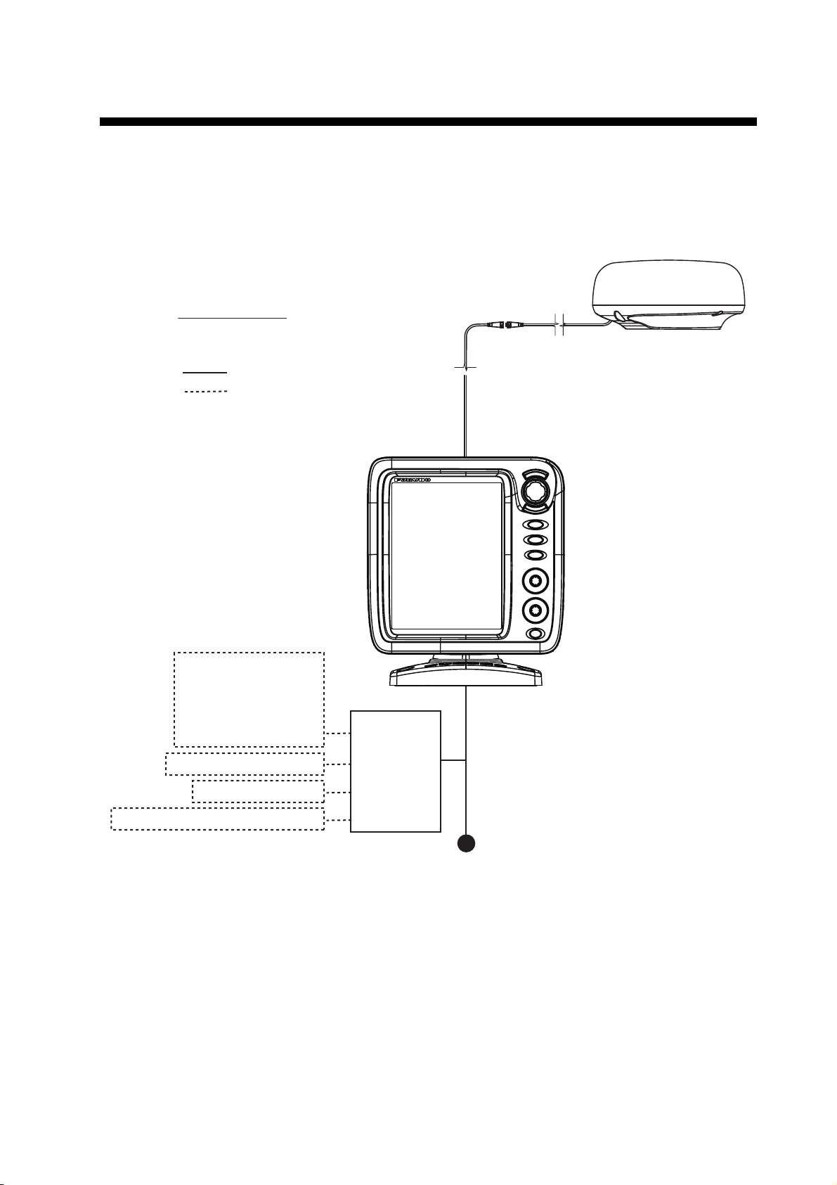
SYSTEM CONFIGURATION
Equipment category
Antenna Unit: Exposed to the weather
Other Equipment: Protected from the weather
Power cable 1.4 m
Antenna cable (FRU-CF-FF-XXM) (10/15/20 m)
* Option: CP03-37630 (30 m)
:Standard supply
Display Unit
RDP-157
MODEL 1815
Antenna Unit
RSB-127-120
RTR-120
GPS navigator
Satellite compass
Heading sensor
Plotter
AIS
DSB transceiver
External Buzzer (OP03-21)
Junction Box (FI-5002)
NMEA Data Converter (IF-NMEA2K2)
Junction Box
(local supply)
Cable Assembly
(FRU-CF-F01)
Power supply
12 - 24 VDC
:Option or local supply
Basic configuration is shown below with solid line.
xi

SYSTEM CONFIGURATION
This page is intentionally left blank.
xii

1. INSTALLATION
CAUTION
1.1 Equipment List
Standard supply
Name Type Code No. Qty Remarks
Display Unit RDP-157 — 1
Antenna Unit RSB-127-120 — 1
Installation
Materials
Spare Parts SP03-17901 001-351-470 1 Fuse for display unit
Accessories FP03-12501 001-464-950 1 For display unit
Template E32-01304-B 000-178-948-11 1 For antenna unit
CP03-35701 001-351-480 For antenna unit
CO03-37501 001-464-940 For display unit
CP03-37600 000-033-122
CP03-37610 000-033-123 15 m cable
CP03-37620 000-033-124 20 m cable
Select
one
10 m cable
(FRU-2P5S-FU-5A-B, Code No.
000-168-869-10)
Optional supply
Name Type Code No. Qty Remarks
Antenna Unit RSB-127-120 — 1
Radome Mounting Bracket OP03-209 001-078-350 1 For fixing antenna
to mast
External Buzzer OP03-21 000-030-097 1
NMEA Data Converter IF-NMEA2K2 000-020-510 1
Junction Box FI-5002 000-010-765 1
Cable Assy. FRU-CF-FF-30M 001-464-270 1 30 m cable
Flush Mount Kit OP03-242 001-464-280 1
1.2 How to Install the Equipment
1.2.1 Display unit
Do not use paint, anti-corrosion products, contact spray or
other items containing organic solvents on the equipment.
The display unit can be installed on a desktop or flush mounted in a console. Do not
install the unit on the overhead or a bulkhead. Select a suitable location for the unit
considering the following points:
Organic solvents can harm paint and plastic, particularly the connectors.
1-1
1. INSTALLATION
• Select a location where the controls can be easily operated.
• Locate the unit away from the direct wind from air conditioners.
• The temperature range in the mounting location should be -15°C(5°F to 55°C(131°F).
• Locate the unit away from devices that emit active gas.
• The mounting location must be well ventilated.
• Select a location where vibration and shock are minimal.
• A magnetic compass will be affected if the display unit is placed too close to the compass. Observe the compass safe distances in the safety instructions to prevent interference to the compass.
• Locate the unit away from direct sunlight to prevent heat build up inside the cabinet
and condensation in the display.
• Keep the unit away from water and water splash. (The unit complies with waterproofing
specification IP5.)
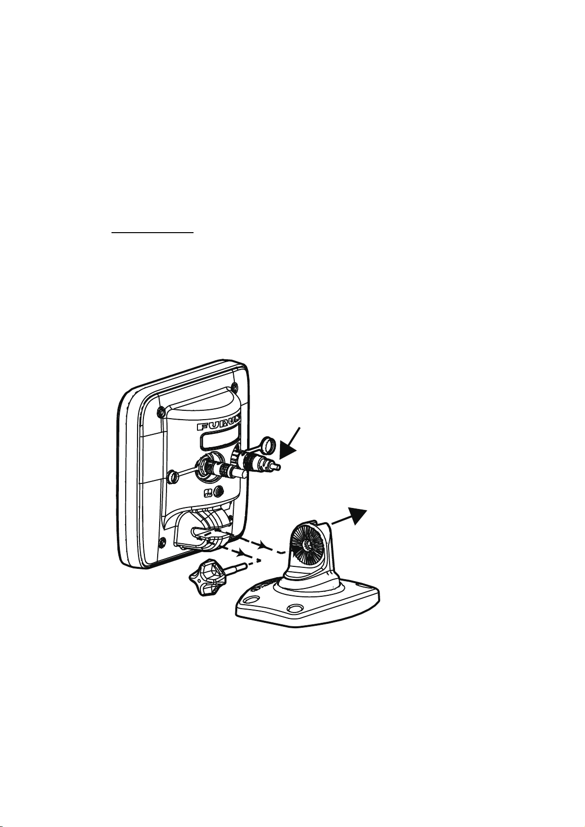
Desktop mount
Fasten the unit to the mounting location as shown below. For mounting dimensions,
see the outline drawing at the back of this manual.
1. Fix the hanger assembly to a desktop with four self-tapping screws (525, supplied). Be sure to follow the recommended maintenance space show in the outline
drawing. Insufficient space may damage the connectors when disconnecting and
reconnecting them.
2. Loosely screw the knob into the hanger assembly.
Cable connector
Loosely fasten knob to hanger assy.
Hanger assy.
Knob
1-2
3. Set the channel in the display unit to the hanger assembly.
4. Adjust the angle of the display unit for comfortable viewing angle.
Note: Do not tilt the unit 90-degree backward or forward. The cable connector
may be damaged if it contacts the bracket.
5. Tighten the knob.
6. Attach the hard cover to the display unit to protect the unit when it is not in use.

1. INSTALLATION
Screw
Hanger cover
Cover sponge
Flush mount (in a console)
The flush mount kit (option) is required to mount the unit in a console. Select a flat
mounting location, and install the unit as shown below.
Note: It is recommended to set up a dedicated breaker when flush mounting the unit,
since it will be difficult to disconnect cables after the unit is installed.
1. Using the paper template (supplied), make a cutout in the mounting location.
2. Unfasten four washer head screws on the rear of the display unit to remove the
bracket cover and the cover sponge.
3. Set the flush mounting sponge (supplied) to the display unit.
4. Screw four threaded rods (supplied) to the display unit.
5. Set the display unit to the cutout.
6. Fasten the display unit from behind with four sets of flat washers, spring washers
and wing nuts (supplied).
1-3
1. INSTALLATION
Antenna
Antenna
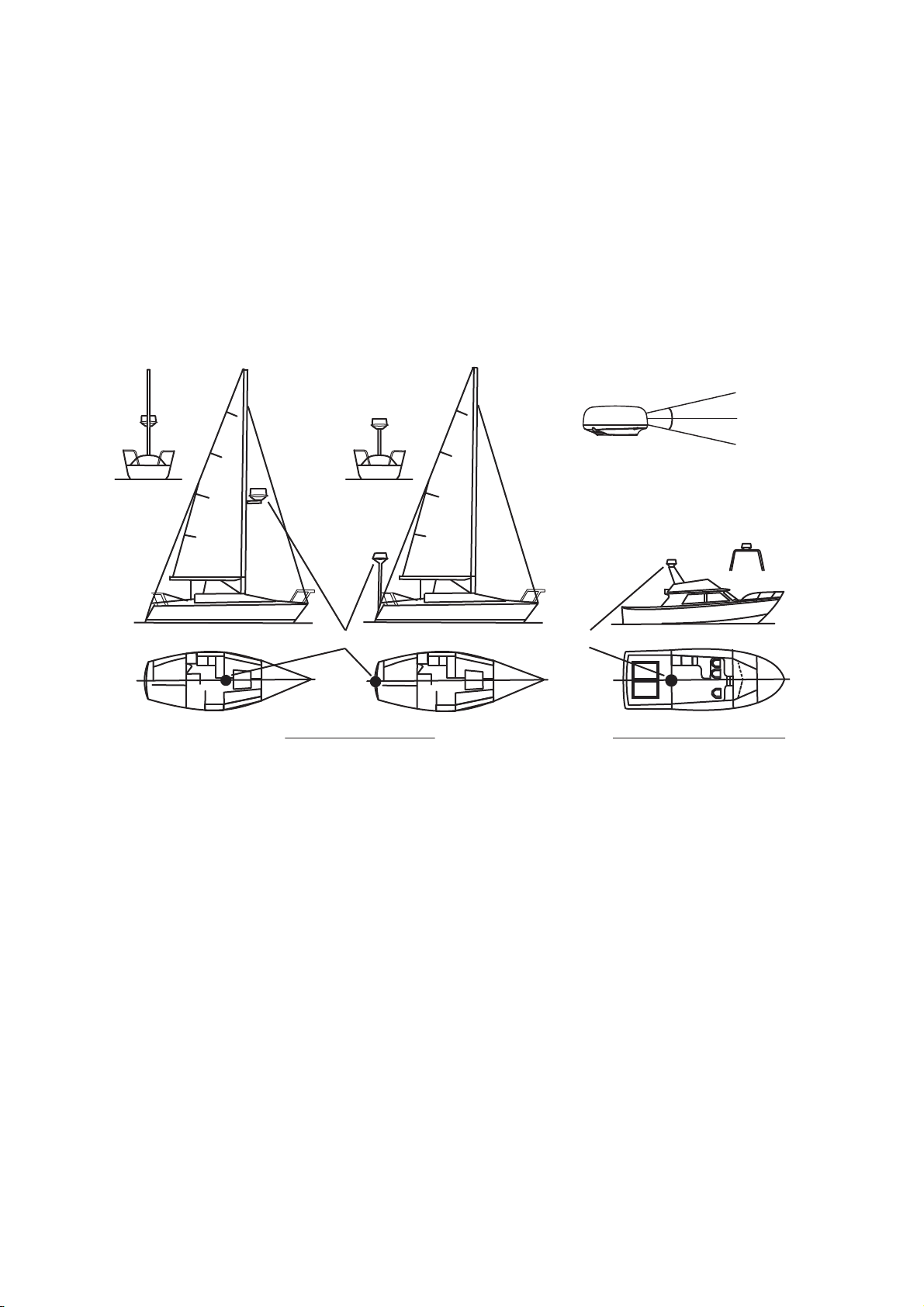
1.2.2 Antenna unit
Select a mounting location for the antenna unit considering the following points.
• Install the unit on a common mast, radar mast, etc.
• Install the antenna unit on a solid location, for example radar arch or on a mast on
a platform. (For sailboats, a mounting bracket is optionally available.) You must put
the antenna unit where there is a good complete view. Make sure that no part of the
superstructure is within the scanning beam. Any obstruction causes shadow sectors. For example, a mast with a diameter smaller than the horizontal beam width
causes only a small blind sector. A horizontal spreader or crosstrees in the same
horizontal plane creates a large obstruction. Install the antenna unit above a horizontal spreader or crosstrees.
Horizontal beam width
12.5°
12.5°
Rear view
Rear view
Rear view
Antenna
Antenna
Antenna
Mounting on a sailboat Mounting on a power boat
Antenna
• To avoid electrical interference, do not run the antenna cable near other electrical
equipment. Also do not run the cable in parallel to power cables.
• Do not install the unit where its motor noise may affect crew or passengers.
• As much as possible install the unit on the ship’s centerline, to prevent misplacement of echoes (wrong bearing) on the display.
• Make sure the mounting location does not allow water to accumulate at the mounting platform.
• A magnetic compass will be affected if the display unit is placed too close to the
compass. Observe the compass safe distances in the safety instructions to prevent
interference to the compass.
1-4
• Do not paint the radome.
• Be sure to follow the recommended maintenance space shown in the outline drawing at the back of this manual.
• If the unit is installed on a large vessel observe the following points.
• The antenna cable comes in lengths of 10, 15 and 20 m (30 m optionally avail-
able). Consider the length of the cable when selecting a mounting location.
• Keep the unit away from smoke and exhaust stacks. Hot air affects antenna per-
formance. Hot air can also damage the unit. The temperature at the mounting location should not exceed 55°C(131°F).
Tools and materials for mounting
▲
Name Usage
Electric drill Drill holes for mounting. Drill bit: 11 mm
Hexagonal wrench Fastening bolts: Diagonal: 6 mm
Silicon sealant For coating exposed parts of bolts
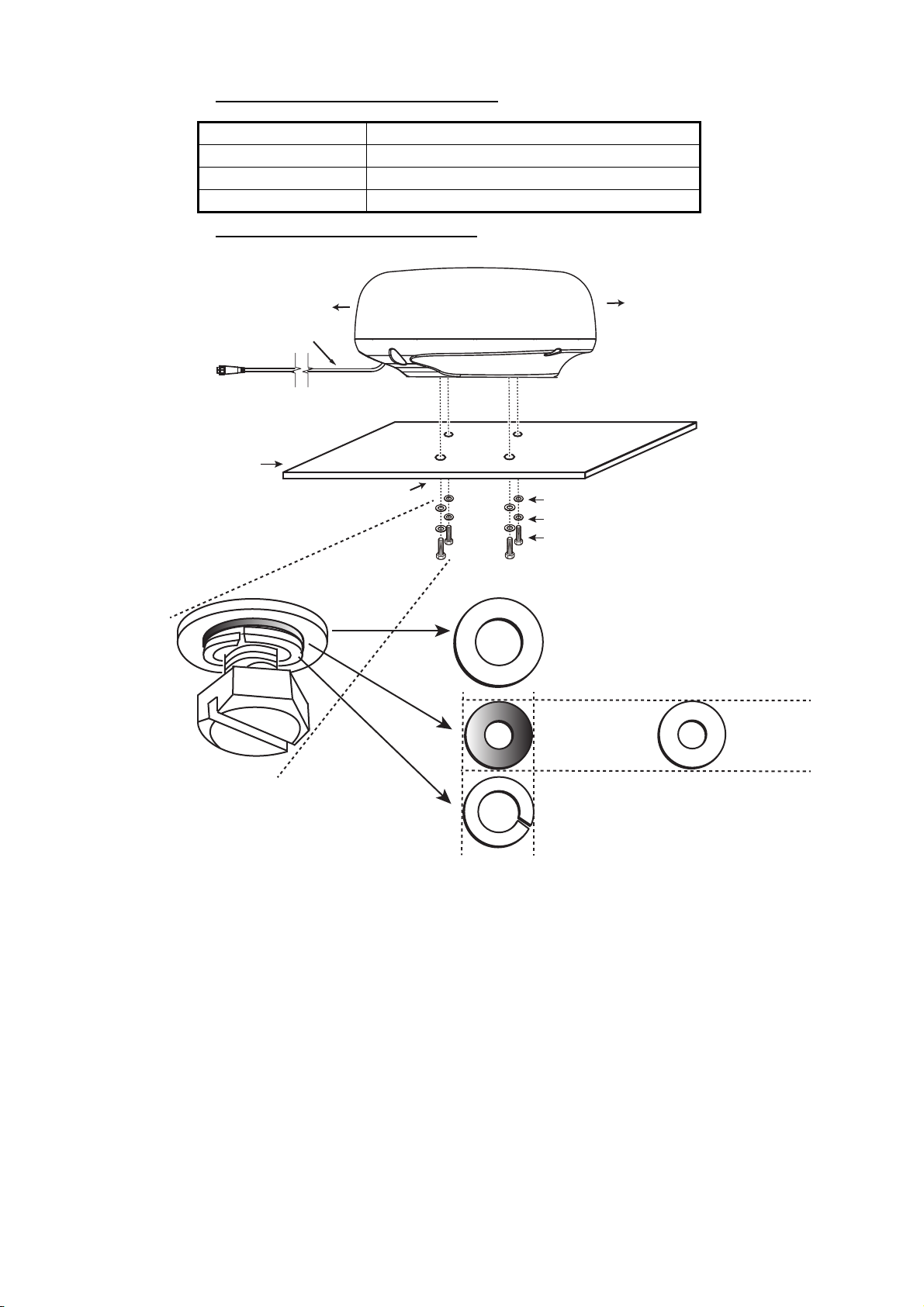
How to mount the antenna unit
1. INSTALLATION
Stern
Power cable (1.4 m)
Mounting platform
Drill holes referring to outline drawing.
Default orientation of
bolt and flat washer
Bow
Align bow mark (
antenna with boat’s centerline.
Flat washer
Spring washer
Hex head bolt (M10×**)
** Bolt length. See table
on next page for details.
Flat washer (large), top in order
Flat washer
(small) middle
in order
Spring washer
(large) last in order.
) on
Bolt hole
Note: The outer diameter of the small flat washer is the same size as the bolt hole.
If the radome is put upside down with only the small flat washer and hex bolt in
place, the hex bolt and flat washer may protrude into the radome and damage the
RT unit. For this reason, DO NOT put the radome upside down when carrying the
radome.
1-5

1. INSTALLATION
Mounting platform
Antenna unit base
Flat washer
Hex bolt
Spring washer
Determine the length of bolts
according to platform thickness.
Marine sealant (local supply)
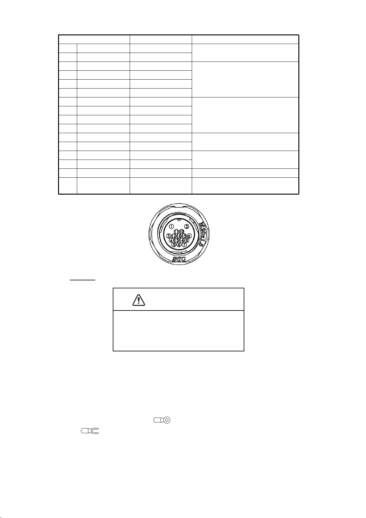
Pin arrangement
10 mm
1. From the bottom of the radome, remove spring washers (M10), flat washers
2. Use the mounting template (supplied) to mark the location of fixing holes in the
3. Lay the antenna unit on the mounting platform with the bow mark() on the an-
(M10) and hex head bolts (M10**).
**: The length of the hex head bolt depends on the thickness of the platform.
See the table below for platform thickness and bolt to use.
Flat washer
Spring washer
Hex head bolt (M10×**)
×4
mounting platform. Be sure to drill the holes parallel with the bow.
tenna unit facing the bow.
4. Use hex bolts*, flat washers and spring washers (removed at step 1) to fasten
the radar sensor to the platform. The torque for the bolts must be 19.6 to 24.5
Nm. Apply marine sealant (local supply) to hex bolt, flat washer and spring
washer as shown below.
*See the figure below to determine the bolt length to use.
Platform thickness Bolt size to use
5 mm or less M1020
6 to 10 mm M1025
More than 10 mm Local supply
5. Connect the power cable to the antenna unit. The pin arrangement is as shown
below.
1-6
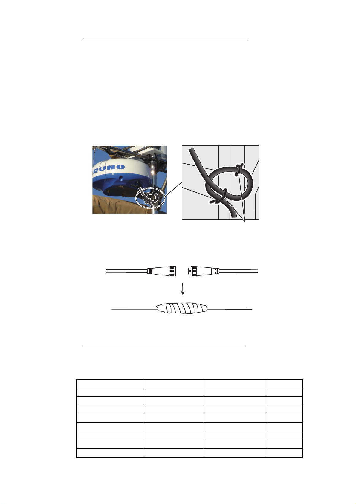
1. INSTALLATION
Loop cable and tie the loop with cable
ties. (Min. bending radius: 80 mm)
Connect and wrap
junction and connectors
with tape.
How to connect the cable assy. to the antenna unit
Observe the following guidelines for connecting the cable assy. to the antenna unit.
• The connectors must not strike any part of the vessel by wind, etc.
• The load applied to the connectors must not be more than their own weight.
• If the cable is passed through a mast on a sailboat, be sure the cable does not
touch ropes (sheet, halyard, etc.).
• Do not fasten the cable to the hull.
1. The cable must be fixed so no tension is applied to the connectors. To prevent
tension, make a loop in the cable close to the sensor and tie the loop with cable
ties, as in the figure below.
2. Wrap the junction of the connectors and the connectors with self vulcanizing
tape for waterproofing.
3. Using a cable tie, fasten the cable to the mast, etc. at the neck of each connec-
tor.
How to use the radome mounting bracket (option)
The optional radome mount lets you fasten the radar sensor to a mast on a sailboat.
Name, Type: Radome Mount (2), OP03-209
Code No.: 001-078-350
Name Type Code No. Qty
Mounting plate 03-018-9001-0 100-206-740-10 1
Support plate (1) 03-018-9005-0 100-206-780-10 1
Support plate (2) 03-018-9006-0 100-206-790-10 1
Bracket (1) 03-028-9101-1 100-206-812-10 1
Bracket (2) 03-028-9102-2 100-206-822-10 1
Fixing plate 03-028-9103-1 100-206-832-10 2
Hex bolt w/washer M820 SUS304 000-162-955-10 10
Hex bolt w/washer M412 SUS304 000-162-956-10 4
1-7

1. INSTALLATION
Fixing plate
Bracket (2)
Bracket (1)
Bracket (2)
Bracket (1)
M8×20
M4×12
M4×12
Mounting
plate
Dwg (1)
Dwg (2) Dwg (3)
M8×20
M8×20
How to assemble the bracket:
1. Fasten the fixing plates to the brackets (1) and (2) with four M412 hex bolts.
2. Fit brackets (1) and (2) loosely with support plates (1) and (2) using four M412
3. Place the mounting plate on the brackets and fix the plate loosely with four
How to fasten the bracket to the mast:
hex bolts, so that the gap between the brackets can be adjusted.
M820 hex bolts.
1. Drill eight holes of 6.5 mm into the mast. Fasten the bracket to the mast with
eight stainless steel rivets (local supply) whose diameter is 6.4 mm.
2. Tighten the bolts on the bracket.
3. Fasten the antenna unit to the bracket with bolts (M1025).
Rivet
M10×25
1-8
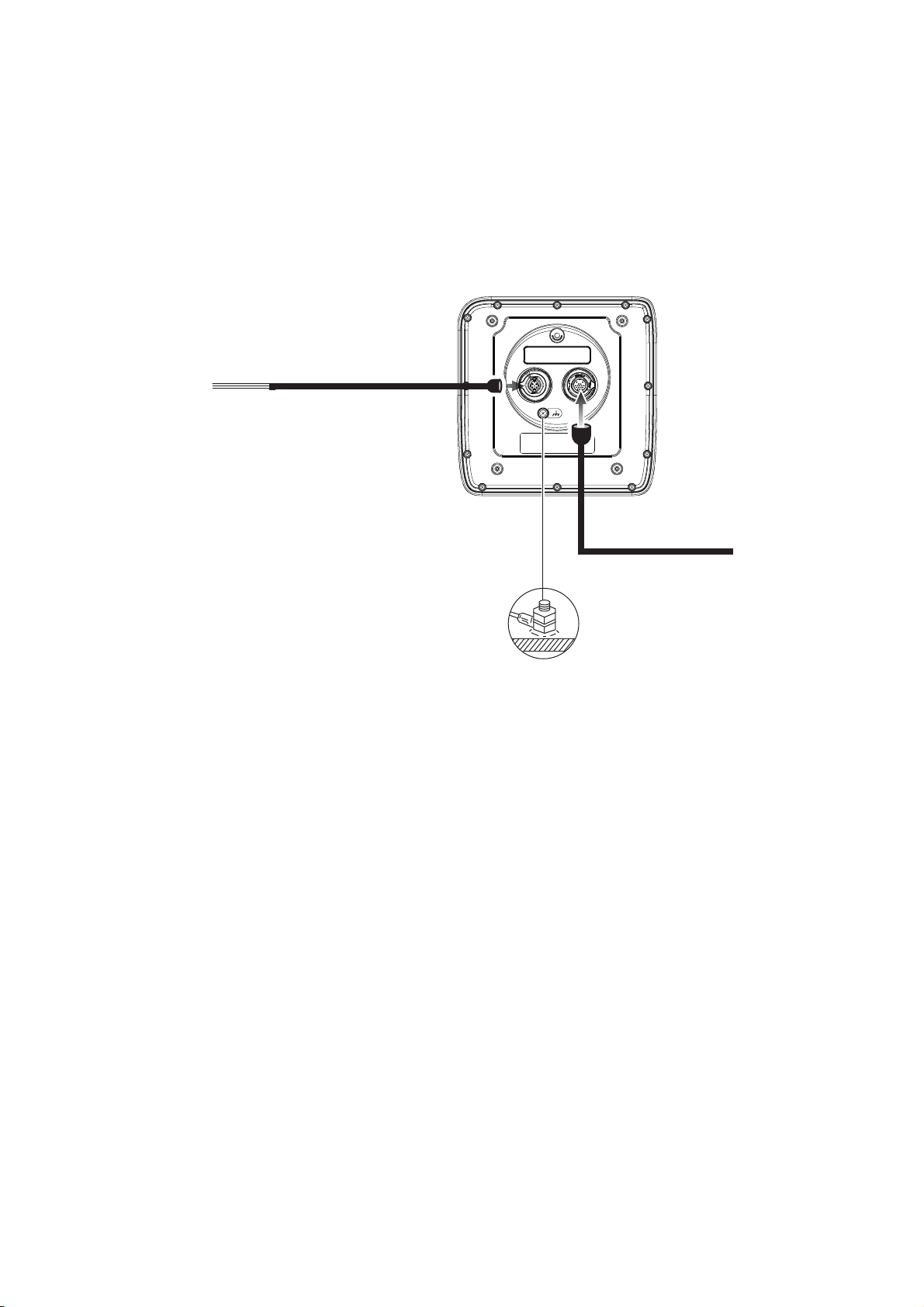
1.3 Wiring
Ground
Power/signal connector
(FRU-CF-F01)
Antenna cable
䠄FRU-CF-FF-**M, 10/15/20 m,
30m optionally available䠅
Ship’s switchboard,
external equipment,
ground terminal, etc.
Use the supplied cable FRU-CF-F01 to connect a satellite compass, heading sensor,
GPS navigator, external buzzer, and power supply to the 12-24 VDC/NMEA connector.
Connect the antenna cable (FU-CF-FF-xxM (10m/15m/20m, 30 m optionally available) to the antenna port. See the interconnection diagram at the back of this manual
for details. Leave slack in the cable to ease maintenance.
1. INSTALLATION
Note 1: The display unit comes with connector caps. Use the caps to cover the connectors whenever the display unit is removed from the boat.
Note 2: Cut unused wires and wrap them with vinyl tape to keep them from touching
one another.
Note 3: Use care when disconnecting cables to prevent damage to their connectors.
Note 4: When an NMEA equipment uses ±12 V supplied from this equipment, do not
connect the cable earth of the signal line of that equipment (for example, satellite compass) to 12 V-P(+)/12 V_M(-).
Note 5: Do not shorten the supplied cable.
1-9
1. INSTALLATION
CAUTION
Connector Color Remarks
1 DC-P-IN(+) RED Power input, 12-24 VDC
2 DC-M-IN(-) BLK
3 TD1-A GRN/BLK(1) IEC61162-2/NMEA1
4 TD1-B GRN/RED(1)
5 RD1-H GRY/BLK(1)
6 RD1-C GRY/RED(1)
7 TD2-A GRN/BLK(2) IEC61162-2/NMEA2
8 TD2-B GRN/RED(2)
9 RD2-H GRY/BLK(2)
10 RD2-C GRY/RED(2)
11 RD3-H GRY/BLK(3) IEC61162-2/NMEA3
12 RD3-C GRY/RED(3)
13 12V-P(+) BRN Power output, 12-24 VDC
14 12V-M(-) ORG
15 EXT-BUZZ-EN WHT External buzzer
16 SHIELD BLK Drain wire, (Connect to ground ter-
minal of ship’s switchboard.)
Ground
Do not fail to ground the display unit.
If the ground is poor or there is no ground, the
radar and other equipment may pick up interference.
Grounding guidelines:
• The ground wire (local supply) should be 2sq or higher.
• The length of the ground wire should be as short as possible.
• For an FRP vessel, fasten a 20 cm30 cm earthing plate to the outside of the boat’s
hull and attach the ground wire to a bolt on the plate.
• Attach a closed-end lug ( ) to the ground wire. Do not use an open-end lug
().
• External equipment whose signal line is connected to ground cannot be directly
connected to this equipment if the positive polarity of the vessel’s DC power is connected to ground.
1-10
1. INSTALLATION
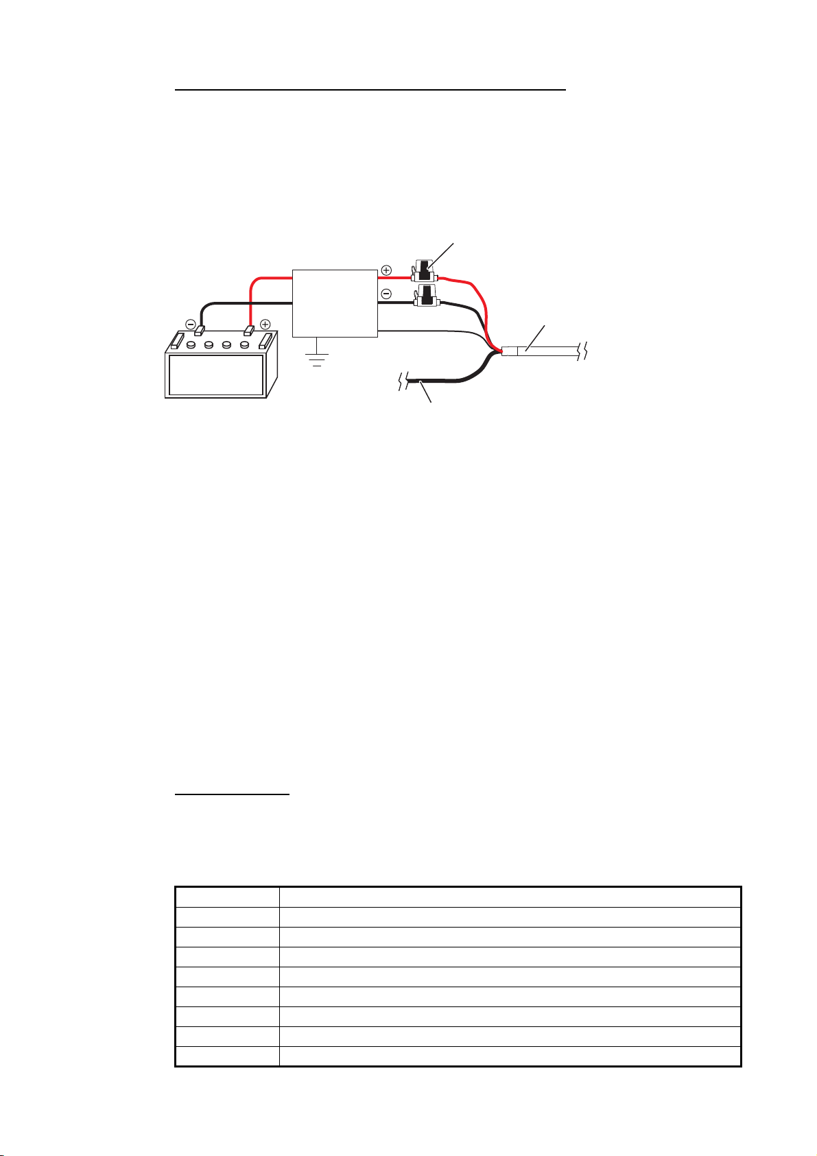
Signal line (External buzzer, etc.)
Display Unit
Cable Assy.
Shield
Distribution
Board
Power Supply
(12-24 VDC)
Fuse holder
BLK
RED
BLK
How to connect the display unit to the power supply
Connect the cable assy. to the power supply (24 VDC).
• Red cable: Connect to the positive (+) terminal. The fuse holder is attached to this
wire.
• Black cable: Connect to the negative (-) terminal.
• Black cable: Shield wire. Connect to ground.
Note 1: To use a12 VDC power supply, connect a DC-DC converter whose output current is at least 5A.
Note 2: This equipment cannot be used with a power supply greater than 24 VDC.
1.4 Input Signal
This radar accepts signals in NMEA format. Three NMEA ports are provided, and sentence handling is common to all ports.
1.4.1 Talker
Every device that sends data has an identification code at the head of the data. The
device that receives the data is for identifying the device that sent the data, and this
code is called the “talker”. This equipment has the talkers GN, GP, GL, GA, and RA.
1.4.2 NMEA I/O sentences
NMEA1/NMEA2
• Talker: Any
• Baud rate: 4800/38400
• NMEA 0183 (IEC 61162-2
Sentence Description
ALR Set alarm state
BWC Bearing and distance to waypoint-Great Circle
BWR Bearing and distance to waypoint - Rhumb Line
DBT Depth Below Transducer
DPT Depth
DTM Data Reference
GGA Global Positioning System Fix Data
GLL Geographic Position
1-11

1. INSTALLATION
Sentence Description
GNS GNSS Fix Data
GSA GNSS DOP and Active Satellites
GSV GNSS Satellites in View
HDG Heading, Deviation & Variation
HDM Heading, Magnetic
HDT Heading True
MTW Water Temperature
MWV Wind Speed and Angle
RMB Recommended Minimum Specific Navigation Information
RMC Recommended Minimum Specific GNSS Data
THS True Heading and Status
TTM Tracked Target Message
VDM AIS VHF Data-link Message
VHW Water Speed and Heading
VTG Course Over Ground & Ground Speed
VWR Wind relative Bearing and Velocity
VWT True Wind Speed and Angle
XTE Cross-Track Error, Measured?
ZDA Time & Date
ALR Set alarm state
BWC Bearing and distance to waypoint - Great Circle
BWR Bearing and distance to waypoint - Rhumb Line
DBT Depth Below Transducer
DPT Depth
NMEA3 (HDG)
Sentence Description
HDG Heading, Deviation & Variation
HDM Heading, Magnetic
HDT Heading True
THS True Heading and Status
VHW Water Speed and Heading
1-12
1.5 Initial Settings
1.5.1 How to select language
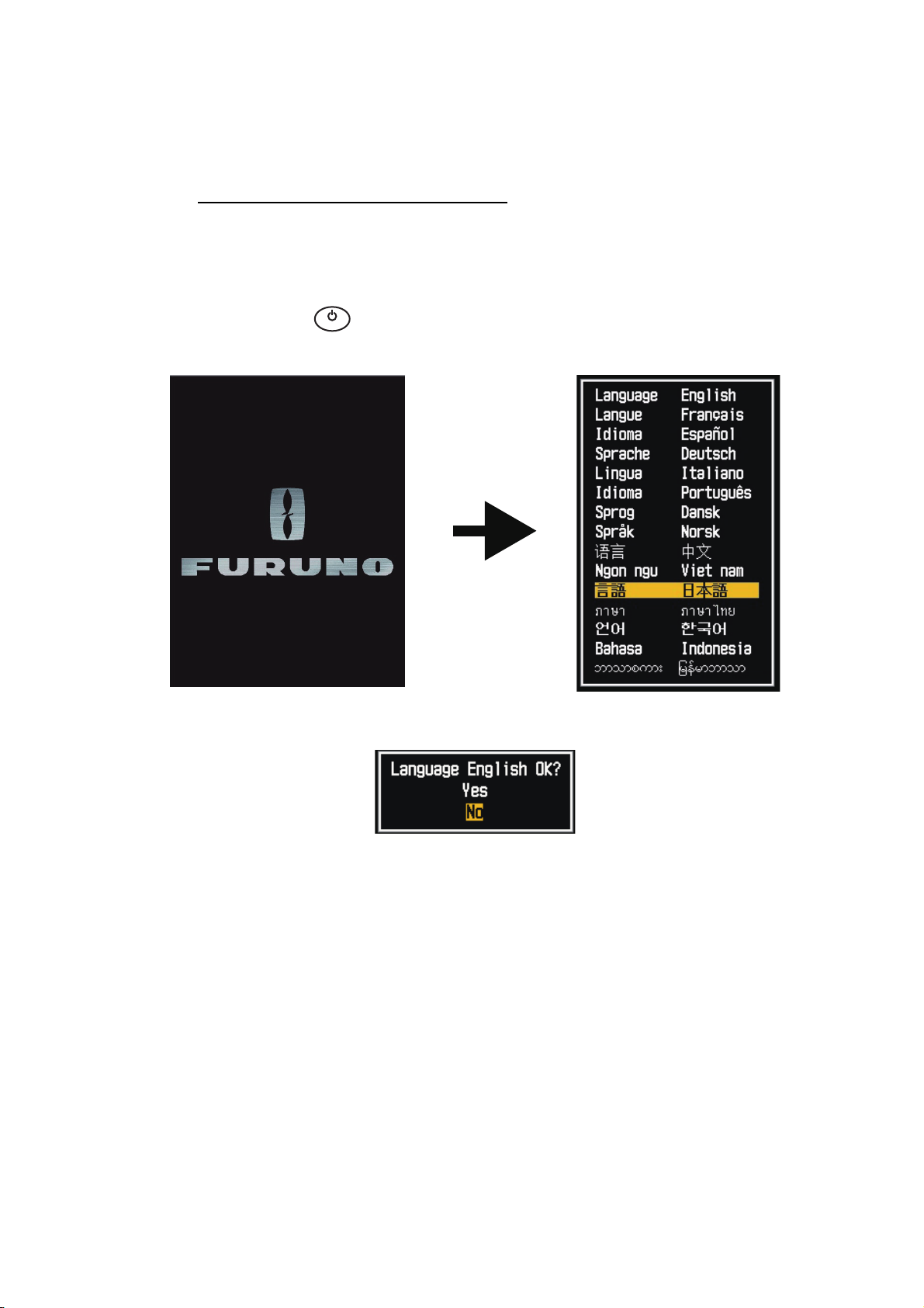
Language selection at initial start up
At the first power on after installation or whenever the memory is cleared, the language selection screen appears. Select your language as shown below. The default
language is English.
㻌
㻌
㼀
1. Press the ( ) key on the display unit to turn on the power. The splash screen
appears followed by the language selection screen.
㼄
1. INSTALLATION
2. Operate the Cursorpad ( or ) to select the language of your choice then press
the ENTER key.
3. Push on the Cursorpad to select [Yes] then press the ENTER key.
4. Press the MENU/ESC key to close the menu.
1-13
1. INSTALLATION
㻌
㻌
㼀
㼄
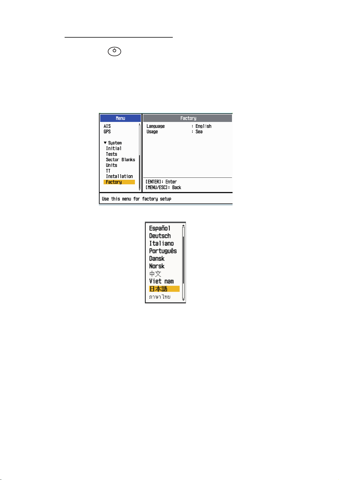
Language selection from the menu
1. Press the ( ) key on the display unit to turn on the power.
2. Press the MENU/ESC key to show the menu.
3. Do the following to access the [Factory] menu.
1) Select [Factory], then press the ENTER key.
2) While holding and pressing the MENU/ESC key, press the ALARM key five
times, press the ENTER key.
4. Select [Language], then press the ENTER key.
5. Select your language, then press the ENTER key.
6. Press the MENU/ESC key to close the menu.
1-14
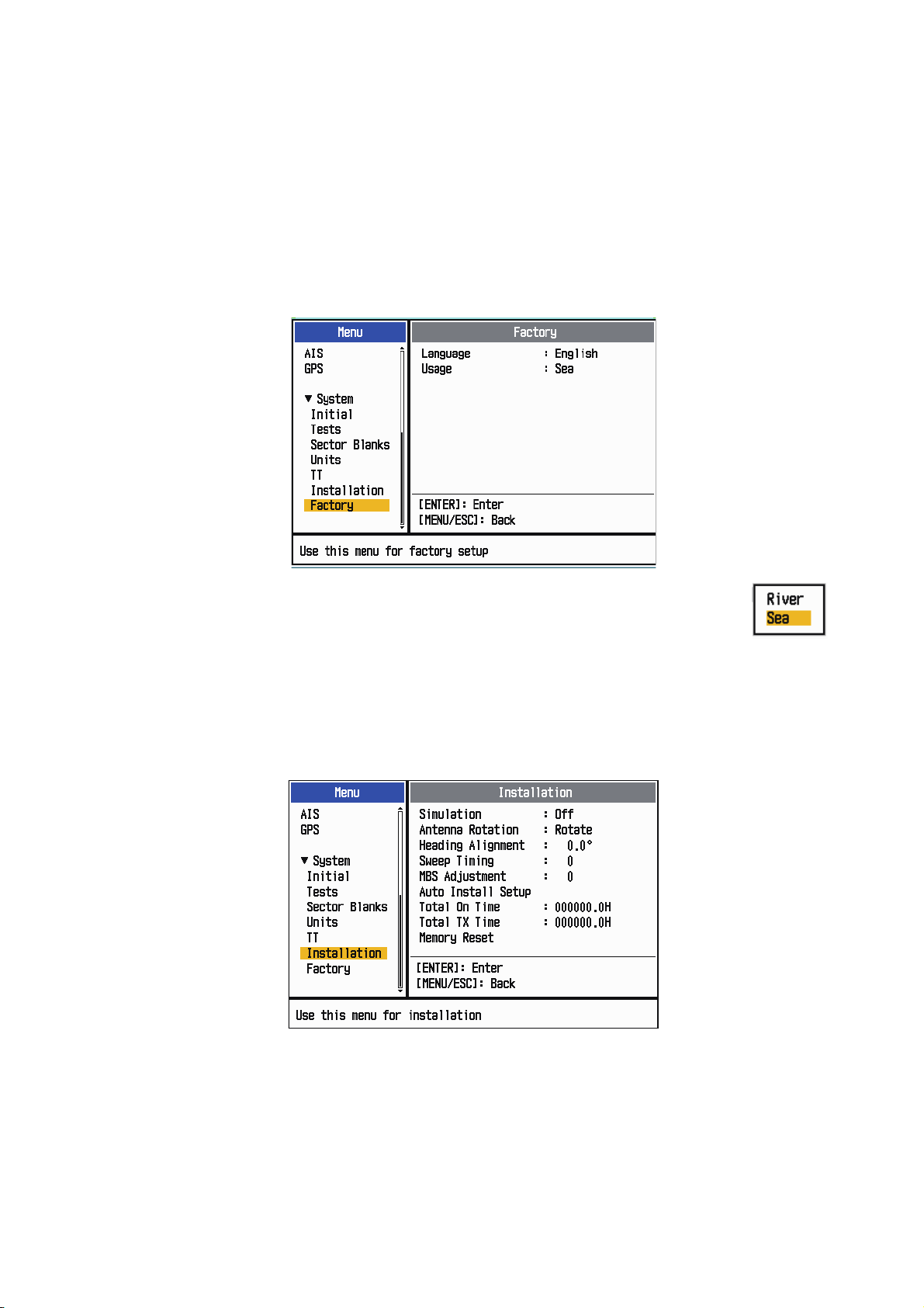
1.5.2 How to select radar application
The radar application setting automatically changes the unit of range measurement
and other settings.
1. Press the MENU/ESC key to show the menu.
2. Do the following to access the [Factory] menu.
1) Select [Factory], then press the ENTER key.
2) While holding and pressing the MENU/ESC key, press the ALARM key five
times then press the ENTER key.
1. INSTALLATION
3. Select [Usage], then press the ENTER key.
4. Select [River] or [Sea] as appropriate, then press the ENTER key.
5. Press the MENU/ESC key to close the menu.
1.5.3 Initial settings
1. Press the MENU/ESC key to show the menu.
2. Select [Installation], then press the ENTER key.
3. While holding and pressing the ENTER key, press the ALARM key five times to
unlock the [Installation] menu.
4. Select the item to set, then press the ENTER key.
5. Select the option required, then press the ENTER key.
6. After setting all items, press the MENU/ESC key to close the menu.
1-15

1. INSTALLATION
(1) Target pulled (2) Correct (3) Target pushed outward
Item description
• [Simulation]: Normally, set to [Off.] To view the demonstration picture, select [On].
• [Antenna Rotation]: Select [Rotate] to rotate the antenna and transmit radar pulses. The [Stop] setting, which transmits radar pulses without rotating the antenna, is
for use by the service technician.
• [Heading Alignment]: You have installed the antenna unit so that the unit faces toward the bow. A target at the front of the boat and aligned with the bow must appear
on the heading line (zero degrees). If the target does not appear on the heading line,
do the procedure shown below to adjust the heading.
1. Set ship heading toward an acceptable target (for example, ship at anchor or
2. Transmit the radar at the range of 0.25 nautical mile and measure the bearing
3. Open the [Installation] menu and select [Heading Adjust].
4. Press the ENTER key to show the heading adjustment window.
5. Press or to set the value measured at the above step 2. Check that the
buoy) at a range between 0.125 and 0.25 nautical mile.
of that target relative to ship heading with an EBL.
target appears on the heading line.
6. Press the ENTER key to finish.
• [Sweep Timing]: This adjustment gives correct radar performance on short ranges.
The radar measures the time required for a transmitted echo to go to the target and
return to the source. The received echo appears on the display according to the
measured time. The sweep must start from the center of the display.A trigger pulse
created in the display unit goes to the antenna unit through the signal cable to activate the transmitter (magnetron). The time taken by the signal to move to the antenna unit changes, according to the length of the signal cable. During this period, the
display unit must wait before the radar starts the sweep. When the display unit is
not adjusted correctly, the echoes from a straight object will not appear as a straight
line. The target appears "pushed" or "pulled" near the picture center. The range to
objects are shown at wrong distances.
1. Transmit on the shortest range, then adjust the gain and the A/C SEA.
2. Visibly select a target that creates a straight line (harbor wall, straight piers).
3. Open the [Installation] menu and select [Timing Adjust].
4. Press the ENTER key to show the timing adjustment window.
5. Press or to make straight the target selected at step 2, then press the EN-
TER key to finish.
1-16
 Loading...