

Page 1

All-in-One Power Center
Centre d’alimentation tout-en-un
Centro de energía todo en uno
Instruction Manual
Manuel d'instructions
Manual de instrucciones
Model/Modèle/Modelo:
FCVSWC54A
FCVSWC42A
Page 2

3
Welcome
English
Thank you and congratulations for purchasing this Furrion® All-In-One Power Center. Before
operating your new product, please read these instructions carefully. This instruction manual
contains information for safe use, installation and maintenance of the product.
Please keep this instruction manual in a safe place for future reference. This will ensure safe
use and reduce the risk of injury. Be sure to pass on this manual to new owners of this product.
The manufacturer does not accept responsibility for any damages due to not observing these
instructions.
If you have any further questions regarding our products, please contact us at
supportfurrion.com
Page 3

4
Contents
English
Welcome ............................................................................................3
Contents ............................................................................................4
Important Safety Instructions ............................................................5
FCC Compliance Class B ........................................................................................5
General Information ..........................................................................6
How your Power Center Works ...............................................................................6
Operational Features ..............................................................................................6
Protective Features of the Power Center ...............................................................6
Product Overview ..............................................................................7
Rear Panel ...............................................................................................................7
Front Panel .............................................................................................................. 7
Installation ........................................................................................8
What’s in the Box ....................................................................................................8
Mounting the Power Center .................................................................................... 8
Wiring Diagram..................................................................................10
Wiring Connection ................................................................................................... 10
Operation ...........................................................................................11
Care and Maintenance .......................................................................12
Replacing Circuit Breaker ....................................................................................... 12
Replacing the Power Converter .............................................................................. 12
Specifications ....................................................................................13
Troubleshooting .................................................................................14
Warranty ............................................................................................15
Page 4

5
Important Safety Instructions
English
CAUTION
● This product should be installed by an
experienced technician. Caution and
care must be taken when servicing this
equipment.
● To prevent severe shock or
electrocution consult your servicing
dealer.
● No serviceable parts inside the unit.
WARNING
● This unit employs components that
tend to produce arcs or sparks.
● To prevent fire or explosion, do not
install in compartments containing
batteries or flammable materials (LP
gas).
CAUTION
● To prevent fire, do not cover or obstruct
ventilation openings.
● Do not mount in zero-clearance
compartment. Overheating may result.
● For continued protection against risk of
fire, or electric shock replace only with
same type and rating of fuse.
CAUTION
● On a monthly basis, check the fluid
level in any battery connected to
RV charging system, follow battery
maintenance procedures.
● This product is not ignition protected
and should not be installed in an LP
compartment.
FCC Compliance Class B
NOTE: This equipment has been tested and
found to comply with the limits for a Class B
digital device, pursuant to Part 15 of the FCC
Rules.
These limits are designed to provide
reasonable protection against harmful
interference when the equipment is
operated in a commercial environment. This
equipment generates, uses, and can radiate
radio frequency energy and, if not installed
and used in accordance with the instruction
manual, may cause harmful interference
to radio communications. Operation of this
equipment in a residential area is likely to
cause harmful interference, in which case
the user will be required to correct the
interference at his own expense.
Page 5

6
General Information
English
How your Power Center Works
The Furrion power center offers breakthrough technologies that help maintain and
lengthen the life of your batteries.
The heart of the power center is the
converter. The built-in microprocessor
constantly monitors the battery voltage and
automatically adjusts the converter output
voltage to provide the proper charging
voltage for fast recharges and long-term
maintenance - the intelligent way to charge
and maintain your RV battery.
Operational Features
The Furrion Smart All-In-One Power Center
is designed with 35A or 45A converter builtin. The converter has two types of battery
selection. It can be switched to Lithium
battery type automatically when Furrion
Lithium battery is connected. This converter
has multiple charging modes to keep your
battery in good condition.
● Converter/charger ratings up to 35Amps
for FCVSWC42A and 45Amps for
FCVSWC54A
● Easy access reverse battery or polarity
protection fuses
● Lead acid and Lithium battery charging
● Special protocol to connect with Furrion
Lithium battery
● Battery Maintenance-free – every 21 days
a new charge cycle begins
Protective Features of the
Power Center
BATTERY REVERSE POLARITY – If a battery
is accidentally hooked up backwards, the
power center converter will be protected by
the fuse.
LOWER INPUT VOLTAGE PROTECTION – If
the input voltage is lower than the preset
limit, the power center converter will shutdown to prevent damage. The unit will return
to normal operation when the voltage returns
to normal.
OVER CURRENT PROTECTION – The power
center converter will automatically shut down
when the output current is higher than rated
current.
OVER TEMPERATURE PROTECTION – If
the temperature inside the power center
converter is too high, the unit will reduce
the input power automatically by 5A each
time until the temperature drops down to
a safe level. If the inside temperature still
exceeds the preset safety level, the unit will
shut down automatically and restart after the
temperature inside drops.
SHORT CIRCUIT PROTECTION – The power
center converter will shut down. Remove
the short circuit and restart power center
converter.
COOLING FAN – The fan will start to run
when temperature of the heat sink is higher
than 50°C. The fan will run fast when the
temperature is up to 60C.
FAN BLOCK PROTECTION – The power
center converter will shut down when the fan
is blocked.
Page 6

7
Product Overview
English
Rear Panel
Fur Bus
Power Input
(120Vac)
Power Output
(12Vdc)
Front Panel
Breaker
Cover
Fan
Fuse
Page 7

8
Installation
English
WARNING
This unit employs components that tend to
produce arcs or sparks. To prevent fire or
explosion, do not install in compartments
containing batteries or flammable
materials (LP gas).
CAUTION
● To prevent fire, do not cover or obstruct
ventilation openings. Do not mount
in zero-clearance compartment.
Overheating may result.
● For continued protection against risk of
fire or electric shock, replace only with
same type and rating of fuse.
What’s in the Box
Make sure you have all the following items
included in the packaging. If any items are
damaged or missing, contact your dealer.
− Power Center x 1
− Instruction Manual x 1
− Warranty Card x 1
Mounting the Power Center
Consult a licensed electrician or an RV
technician for installation assistance.
1. Select a mounting location near the
shore power and battery (batteries). A
minimum compartment size of 3 cubic
feet is recommended. Failure to provide
adequate ventilation will prevent the
power center from supplying full output
power.
2. Cut a rough opening (to the dimension
outlined in Fig. 1) on the RV wall to allow
the power center to slide in easily.
Fig. 1
RV Wall
10 9/16 in
268.0 mm
7 in
178.0 mm
3. Push the power center front cover around
to the position of ‘F” mark and rotate
downwards to fully open it. (Fig. 2)
Fig. 2
4. Loosen the screws that hold the housing
at the four corners using a Phillips
screwdriver. (Fig. 3)
Fig. 3
5. Pull to remove the housing from the unit.
(Fig. 4)
Page 8

9
Installation
English
Fig. 4
6. Connect the power center to Furrion
LiFePO4 battery. Red wire to red wire,
white wire from converter to black post on
battery. Red is positive (+), White is negative
(-). Connect the RJ25 wire to power center
RJ25 port. See ‘Wiring Diagram’ section on
how to connect the wires.
7. Slide the power center into the opening
area and affix with 4 self-tapping screws
(#8-18 thread) (not supplied). (Fig.5 and
Fig. 6)
Fig. 5
Fig. 6
8. Replace the housing to the power center
and tighten the screws at the four
corners. (Fig. 7 and Fig. 8)
NOTE: Do not over tighten. Damage to
the housing may occur which will void the
warranty.
Fig. 7
Fig. 8
9. Test the power center under full load
conditions in its intended mounting
location to ensure proper ventilation.
Page 9

10
Wiring Diagram
English
Wiring Connection
WARNING: Make sure no AC power is coming into the RV from either the shore power cord or
an on-board generator.
The fuse rating that the manufacturer suggests for the output fuses will be marked on the unit.
Replace only with same type and rating.
NOTE: If the reverse battery protection fuses are blown during connection, be sure that the
battery has been connected properly, then replace the fuses with the same rating as the
original.
Neutral Terminal Bar (White Wire)
AC Ground Bar (Green
and Ground wires)
Main
Breaker
LINE
Fur Bus to
Furrion
Battery
12Vdc Positive Output
Main Breaker Holder
Red to Battery +
To Converter +
Reverse
Protection Fuse
30A
Page 10

11
Operation
English
Many options will be installed prior to the
purchase of your new RV, however there are a
few options that you should be aware of while
operating your new power center.
The built-in microprocessor selects the best
mode for your battery automatically and
determines which operating mode is best
suited to recharge or maintain optimum
battery condition.
CHARGING FLOW CHART
Time (Hrs)
Voltage (V)
DESULPHATION CHARGE PULSE
CHARGING
If the initial battery voltage is less than 10V,
the charger will start desulphation mode with
pulse charge profile. The pulse charge time
will be 10 minutes.
NOTE: This charging phase is only available
for Lead Acid Battery.
SOFT START CONSTANT CURRENT
CHARGING
If at the initial bulk charging, the battery
voltage is less than 11Vdc due to deep
discharge, the charger will go with soft
charge. The bulk charging current is reduced
to half of the maximum current until battery
voltage is higher than 11Vdc or 10 minutes
(whichever is longer) then switches to bulk
charge.
BULK CHARGE CONSTANT CURRENT
CHARGING
Normally the battery is charged at constant
maximum current until it rises to the bulk
voltage level. The charging voltage changes
with the battery voltage. If the charger cannot
go to absorption mode within 20 hours, the
charger will automatically go to float mode to
prevent over charge of the battery. This is the
safety timer.
ABSORPTION CHARGE CONSTANT
VOLTAGE CHARGING
When the battery voltage rises to the bulk
voltage level, the charging will switch to
constant voltage charging. Charger will
switch to float stage after 90 or 180 minutes
of absorption charge (90 Minutes for LiFePO4
battery, 180 Minutes for Lead Acid Battery).
FLOAT CHARGE CONSTANT VOLTAGE
CHARGING
In this stage, the battery is full and only
takes in the amount of current necessary for
maintaining the capacity. The charger will
switch to bulk charge, if the battery current
is higher than 50% of rated current for 5
minutes or the battery voltage is lower than
12.5Vdc for 5 minutes. If the charger remains
at this mode with charging current less than
20% of bulk current for over 60 hours, the
charger will go into the standby mode.
STANDBY MODE CONSTANT VOLTAGE
CHARGING
In this stage, the charging voltage at this
mode will be 13.2Vdc. This is only for
maintaining the capacity. The charger will
switch to a new cycle after 5 minutes when
the current is higher than 6A.
NEW CYCLE CHARGE EVERY 21 DAYS
Charger will start a new cycle charging of
bulk to absorption to float every 21 days
in either standby or float mode. This new
cycle of charging will refresh the battery
to prevent separation of the electrolyte &
keep the electrode plates in good condition.
The standby auto new cycle charge per 21
days are designed to keep the battery in
good working condition during long period
of resting of the caravan or back up battery
application.
Page 11

12
Care and Maintenance
English
Replacing Circuit Breaker
A replacement or additional circuit breaker shall be of the same manufacturer, type designation
and equal or greater interrupting rating. Main circuit breaker can be used with 30A, branch
circuit can be used with 20A or 15A.
“Short-Circuit-Current” rating for the breaker should be 10,000A.
All the circuit breaker need to be UL
®
-Listed
Acceptable circuit breakers are as follows:
Manufacturer Model/Type
ITE/Siemens QP/QT
Square D HOM/HOMT
Eaton BR
Replacing the Power Converter
IMPORTANT: Make sure all power is disconnected before proceeding.
If you should need to replace the power converter for any reason, follow the steps below to
safely remove the converter section.
1. Remove the hot wires, neutral and ground that lead to the converter on the AC side.
2. Remove the converter output wires from the DC board, ground and positive.
3. Finally unscrew the screws that hold the metal converter plate to the plastic housing.
For factory repairs, return only the converter section. Make sure you use proper packaging to
ensure the product’s safe arrival.
Do not replace the converter section unless the following checks have been performed:
1. Use an AC voltmeter to check for the proper voltage at the 120Vac breaker that the
converter is connected to. This voltage should be between 105 and 130 volts.
2. Remove the reverse battery fuses and check the converter output from the CONVERTER
GND to the CONVERTER POS terminals on the DC board. This should be 13.6Vdc.
3. Check the reverse battery fuses. These fuses will only blow if the battery or DC output leads
were connected reversed, even for a moment. If they are blown check the polarity of the
battery connections before replacing them.
4. If the converter output is not present and there is AC to the converter, the converter is
defective.
Page 12
13
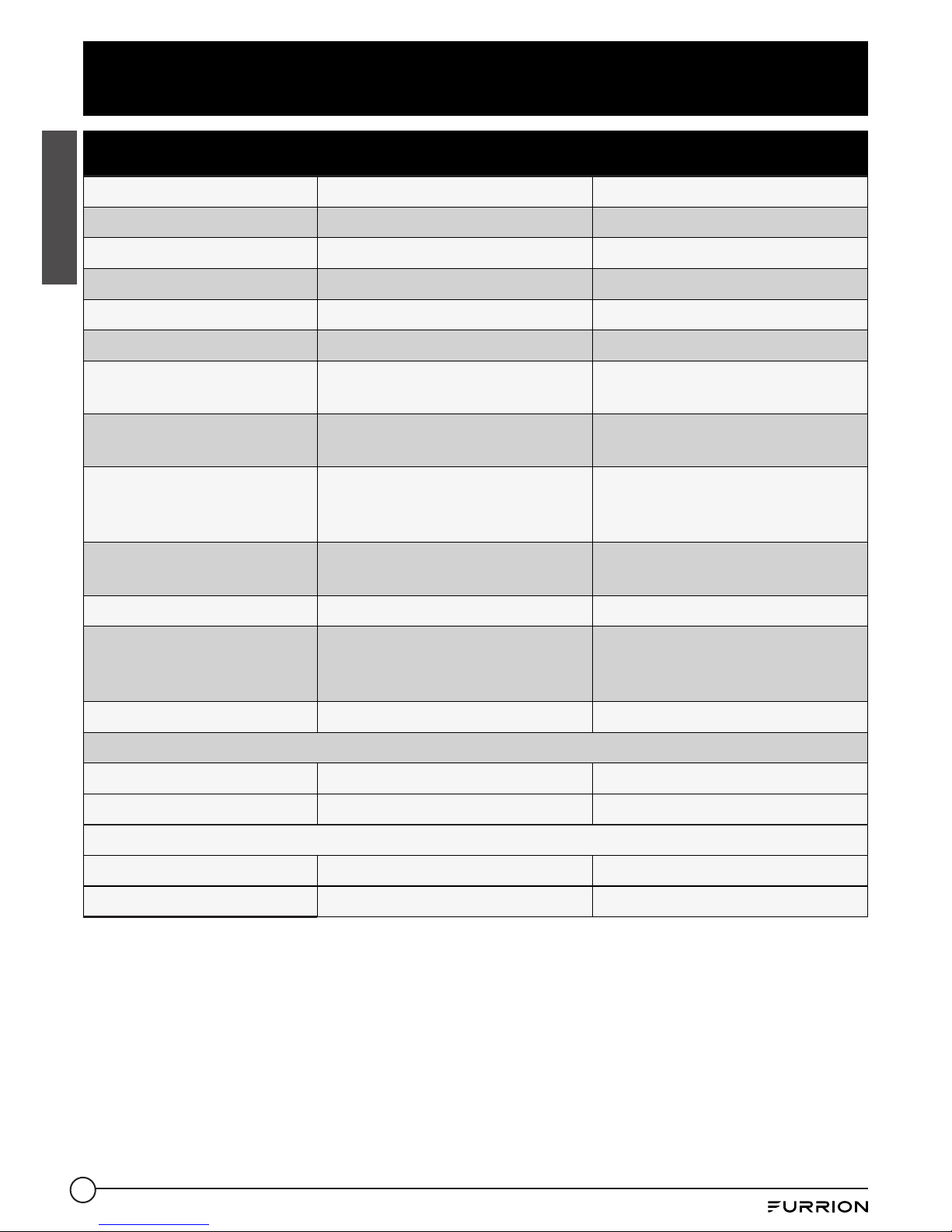
Specifications
English
Technical Specification
FCVSWC42A FCVSWC54A
Standby Voltage 13.2V 13.2V
Charge Current 35A 45A
Operation Voltage Range 105Vac to 132Vac / 60Hz 105Vac to 132Vac / 60Hz
Full Load Input Power 615W 790W
No Load Input Current 250mA 250mA
Full Load Input Current
(120V/60Hz)
7A 8.8A
Efficiency (at LiFePO4)
(120Vac)
>80% >80%
Line Regulation At Full
Load (@input voltage105V
to 132V)
3% 3%
Load Regulation (10%100% Load)
3% 3%
Certification UL458/UL67/FCC PART 15b UL458/UL67/FCC PART 15b
Working Environment
-10°C to 50°C/14°F to 122°F
(Higher temperature will be
de-rating)
-10°C to 50°C/14°F to 122°F
(Higher temperature will be
de-rating)
Storage Environment -20°C to 70°C/-4°F to 158°F -20°C to 70°C/-4°F to 158°F
LiFePO4 Battery
Bulk 14.6 V 14.6 V
Float 13.6V 13.6V
Lead Acid Battery
Bulk 14.4V 14.4V
Float 13.4V 13.4V
Page 13
14
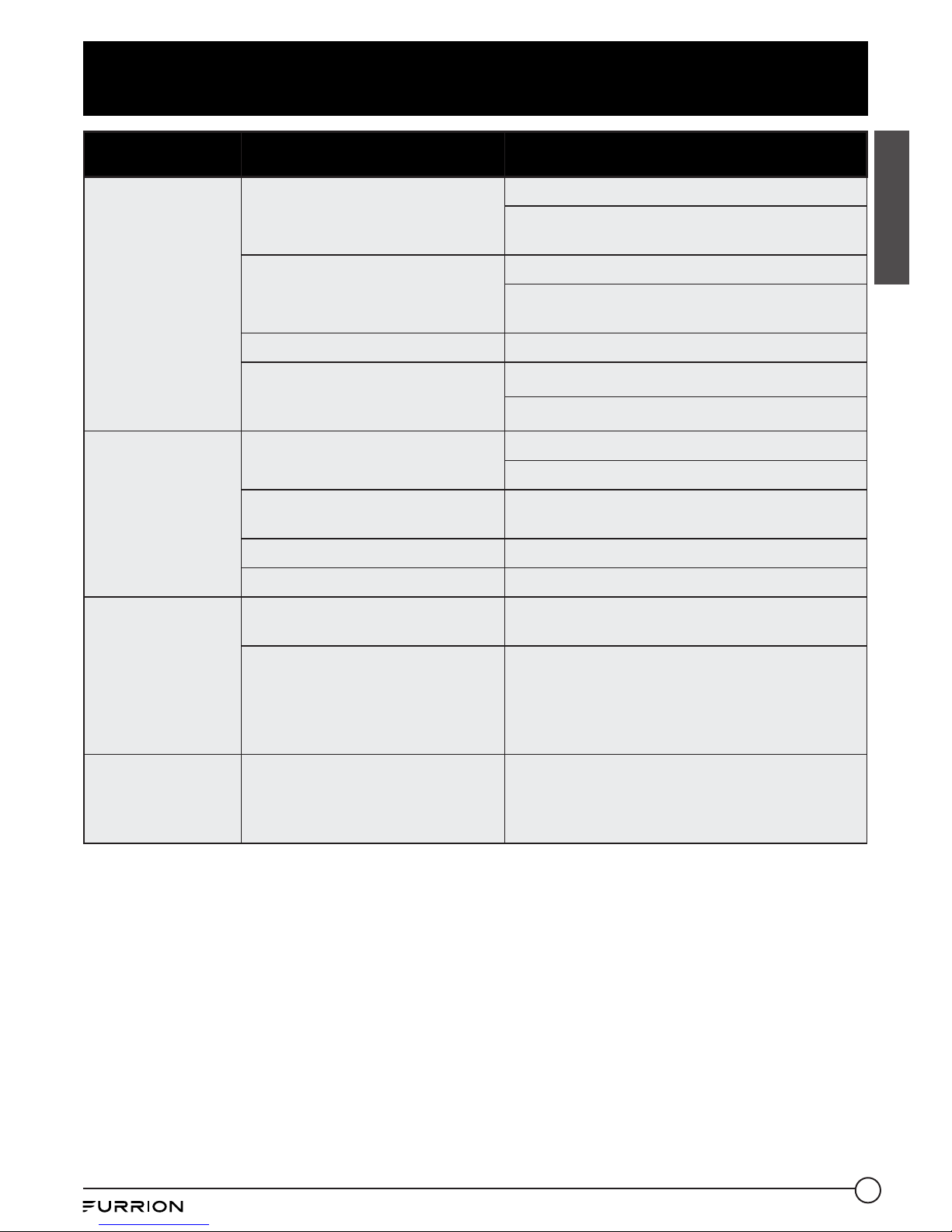
Troubleshooting
English
PROBLEM POSSIBLE CAUSES ACTION
No Output
120VAC supply not connected
Connect power supply
Check AC distribution panel for proper
operation
Reverse battery fuses blown (See
page 1 for location)
Check for reverse battery connection.
Replace fuses with same type and rating (See
page 2)
Short circuit Trace RV circuits for possible fault
Unit has shut down due to lower
voltage
Check input voltage
Correct input voltage
Low Output
Compartment gets too hot
Check air flow to the converter
Improve ventilation to the compartment
Excessive load for converter
Reduce load requirements or install larger
converter
Input voltage too low Correct input supply voltage
Bad battery cell(s) Replace battery
Intermittent or
no Output on
Generator, works
on Shore Power
Unit has shutdown due to lower
voltage.
Add another load to the generator, this may
reduce the “spikes” to an acceptable level
Some generators exhibit
excessive voltage spikes on the
AC power output, this may cause
the over voltage protection to
shut the unit down
Contact generator manufacturer for possible
defect in the generator
Open Fuse
Indicator lit
(See page 1 for
location)
Fuse open Replace fuse with same type and rating
Page 14

15
English
Warranty
Furrion warrants for a period of 1 year from date of retail purchase by the original end-use
purchaser, that this product, when delivered to you in new condition, in original packaging,
from a Furrion authorized reseller and used in normal conditions, is free from any defects
in manufacturing, materials, and workmanship. In case of such defect, Furrion shall replace
or repair the product at no charge to you. This warranty does not cover: products where the
original serial numbers have been removed, altered or cannot readily be determined; damage
or loss caused by accident, misuse, abuse, neglect, product modification, failure to follow
instructions in instruction manual, commercial or industrial use; damage or loss caused to the
decorative surface of product; to any data, software or information; and normal wear and tear.
This warranty only protects the original end-user (“you”) and is not transferable; any attempt to
transfer this warranty shall make it immediately void. This warranty is only valid in the country
of purchase.
THIS WARRANTY AND REMEDIES SET FORTH ABOVE ARE EXCLUSIVE AND IN LIEU OF ALL
OTHER WARRANTIES, REMEDIES AND CONDITIONS, WHETHER ORAL OR WRITTEN, EXPRESS
OR IMPLIED. FURRION SPECIFICALLY DISCLAIMS ANY AND ALL IMPLIED WARRANTIES,
INCLUDING, WITHOUT LIMITATION, WARRANTIES OF MERCHANTABILITY AND FITNESS FOR
A PARTICULAR PURPOSE. IF FURRION CANNOT LAWFULLY DISCLAIM IMPLIED WARRANTIES
UNDER THIS LIMITED WARRANTY, ALL SUCH WARRANTIES, INCLUDING WARRANTIES OF
MERCHANTABILITY AND FITNESS FOR A PARTICULAR PURPOSE ARE LIMITED IN DURATION
TO THE DURATION OF THIS WARRANTY.
No Furrion reseller, agent, or employee is authorized to make any modification, extension, or
addition to this warranty.
Page 15

16
English
Warranty
FURRION IS NOT RESPONSIBLE FOR DIRECT, INDIRECT, SPECIAL, INCIDENTAL OR
CONSEQUENTIAL DAMAGES RESULTING FROM ANY BREACH OF WARRANTY OR CONDITION,
OR UNDER ANY OTHER LEGAL THEORY, INCLUDING BUT NOT LIMITED TO LOST PROFITS,
DOWNTIME, GOODWILL, DAMAGE TO OR REPLACEMENT OF ANY EQUIPMENT OR PROPERTY,
ANY COSTS OF RECOVERING, REPROGRAMMING, OR REPRODUCING ANY PROGRAM OR DATA
STORED IN OR USED WITH FURRION PRODUCTS. FURRION’S TOTAL LIABILITY IS LIMITED
TO THE REPAIR OR REPLACEMENT OF THIS PRODUCT PURSUANT TO THE TERMS OF THIS
WARRANTY.
SOME STATES DO NOT ALLOW THE EXCLUSION OR LIMITATION OF INCIDENTAL OR
CONSEQUENTIAL DAMAGES OR EXCLUSIONS OR LIMITATIONS ON THE DURATION OF IMPLIED
WARRANTIES OR CONDITIONS, SO THE ABOVE LIMITATIONS OR EXCLUSIONS MAY NOT APPLY
TO YOU. THIS WARRANTY GIVES YOU SPECIFIC LEGAL RIGHTS, AND YOU MAY ALSO HAVE
OTHER RIGHTS THAT VARY BY STATE OR (WHERE APPLICABLE IN THE COUNTRIES WHERE
FURRION HAS NON-US/CANADIAN AUTHORIZED DEALERS) COUNTRY. NO ACTION OR CLAIM
TO ENFORCE THIS WARRANTY SHALL BE COMMENCED AFTER THE EXPIRATION OF THE
WARRANTY PERIOD.
Keep your receipt, delivery slip, or other appropriate payment record to establish the warranty
period. Service under this warranty must be obtained by contacting Furrion at
warranty@furrion.com
Product features or specifications as described or illustrated are subject to change without
notice.
Page 16

17
Bienvenue
Français
Merci et félicitations pour l’achat de ce centre d’alimentation tout-en-un de Furrion®. Avant
utiliser votre nouvel appareil, veuillez lire ces consignes attentivement. Le présent guide
d’utilisation contient des informations permettant l’utilisation, l’installation et l’entretien en
toute sécurité de l’appareil.
Veuillez conserver le présent guide d’utilisation en lieu sûr pour vous y référer ultérieurement,
afin d’assurer votre sécurité et de réduire les risques de blessure. Veuillez aussi remettre le
présent manuel à tout nouveau propriétaire de cet appareil.
Le fabricant décline toute responsabilité en cas de dommages dus au non-respect des
présentes consignes.
Si vous avez des questions sur nos produits, veuillez nous contacter : support@furrion.com
Page 17

18
Contenu
Français
Bienvenue ..........................................................................................17
Contenu .............................................................................................18
Consignes importantes sur la sécurité ..............................................19
Conformité FCC Classe B .......................................................................................19
Informations générales .....................................................................20
Comment fonctionne votre centre d’alimentation..................................................20
Caractéristiques opérationnelles ...........................................................................20
Caractéristiques de protection du centre d’alimentation ......................................20
Présentation du produit .....................................................................21
Panneau arrière ......................................................................................................21
Panneau avant ......................................................................................................... 21
Installation ........................................................................................22
Contenu de la boîte .................................................................................................22
Montage du centre d’alimentation .......................................................................... 22
Schéma de câblage ............................................................................24
Connexion de câblage .............................................................................................24
Fonctionnement .................................................................................25
Soins et entretien ..............................................................................26
Remplacement du disjoncteur ................................................................................26
Remplacement du convertisseur de puissance .....................................................26
Caractéristiques ................................................................................27
Dépannage .........................................................................................28
Garantie .............................................................................................29
Page 18

19
Consignes importantes sur la sécurité
Français
MISE EN GARDE
● Ce produit doit être installé par un
technicien expérimenté. Une attention
et des précautions particulières doivent
être prises lors de l’entretien de cet
équipement.
● Pour éviter toute décharge électrique
grave ou électrocution, consultez votre
détaillant.
● Il n’y a aucune pièce réparable à
l’intérieur de l’unité.
ATTENTION
● Cette unité utilise des composants qui
ont tendance à produire des arcs ou
des étincelles.
● Pour éviter un incendie ou une
explosion, ne pas l’installer dans des
compartiments contenant des batteries
ou des matériaux inflammables (p.ex.,
gaz de pétrole liquéfié).
MISE EN GARDE
● Pour éviter les incendies, ne pas
couvrir ou obstruer les ouvertures de
ventilation.
● Ne pas monter l’unité dans un
compartiment à dégagement zéro. Une
surchauffe peut en résulter.
● Pour une protection continue contre les
risques d’incendie ou d’électrocution,
remplacez le fusible uniquement par
un fusible du même type et du même
calibre.
MISE EN GARDE
● Tous les mois, vérifiez le niveau de
liquide dans toute batterie connectée
au système de charge du VR et suivez
les procédures d’entretien de la
batterie.
● Ce produit n’est pas protégé contre
l’inflammabilité et ne doit pas être
installé dans un compartiment de gaz
de pétrole liquéfié (GPL).
Conformité FCC Classe B
REMARQUE: Cet équipement a été testé et
déclaré conforme aux limites d’un appareil
numérique de classe B, conformément à la
partie 15des règles de la FCC.
Ces limites sont conçues pour fournir
une protection raisonnable contre les
interférences nuisibles lorsque l’équipement
est utilisé dans un environnement
commercial. Cet équipement génère, utilise
et peut émettre de l’énergie radiofréquence
et, s’il n’est pas installé et utilisé
conformément au manuel d’instructions,
peut causer des interférences nuisibles aux
communications radio. Le fonctionnement
de cet équipement dans une zone
résidentielle est susceptible de provoquer
des interférences nuisibles, auquel cas
l’utilisateur devra corriger ces interférences
à ses frais.
Page 19

20
Informations générales
Français
Comment fonctionne votre
centre d’alimentation
Le centre d’alimentation Furrion offre des
technologies révolutionnaires qui aident à
maintenir et à prolonger la durée de vie de
vos batteries.
Le coeur du centre d’alimentation est le
convertisseur. Le microprocesseur intégré
surveille constamment la tension de la
batterie et règle automatiquement la tension
de sortie du convertisseur pour fournir
la tension de charge appropriée pour des
recharges rapides et une maintenance à long
terme - la manière intelligente de charger et
d’entretenir votre batterie de VR.
Caractéristiques opérationnelles
Le centre d’alimentation intelligent
tout en un de Furrion est conçu avec un
convertisseur 35A ou 45A intégré. Le
convertisseur comporte deux types de
sélection de batterie. Il peut être commuté
automatiquement sur le type de batterie au
lithium lorsqu’une batterie au lithium Furrion
est connectée. Ce convertisseur dispose de
plusieurs modes de charge pour garder votre
batterie en bon état.
● Convertisseur / chargeur jusqu’à 35A
pour le modèle FCVSWC42A et 45A pour
le modèle FCVSWC54A
● Accès facile aux fusibles de protection
d’inversion de polarité de la batterie
● Recharge les batteries au plomb et au
lithium
● Protocole spécial pour se connecter avec
une batterie au lithium Furrion
● Batterie sans entretien - tous les
21jours, un nouveau cycle de charge
commence
Caractéristiques de protection
du centre d’alimentation
POLARITÉ INVERSE DE LA BATTERIE Si
une batterie est accidentellement branchée
de façon inverse, le convertisseur du centre
d’alimentation sera protégé par le fusible.
PROTECTION DE TENSION D’ENTRÉE
INFÉRIEURE Si la tension d’entrée
est inférieure à la limite prédéfinie, le
convertisseur du centre d’alimentation
s’éteint pour éviter tout dommage. L’appareil
reprendra son fonctionnement normal
lorsque la tension reviendra à la normale.
PROTECTION CONTRE LES SURINTENSITÉS
Le convertisseur du centre d’alimentation
s’éteint automatiquement lorsque le courant
de sortie est supérieur à la valeur nominale
du courant.
PROTECTION CONTRE LA SURCHAUFFE Si
la température à l’intérieur du convertisseur
du centre d’alimentation est trop élevée,
l’unité réduit automatiquement la puissance
d’entrée de 5A jusqu’à ce que la température
baisse jusqu’à un niveau sécuritaire. Si la
température intérieure dépasse toujours le
niveau de sécurité prédéfini, l’unité s’éteint
automatiquement et redémarre après une
baisse de la température à l’intérieur.
PROTECTION DE COURT CIRCUIT Le
convertisseur du centre d’alimentation
s’éteint en cas de court-circuit. Corrigez le
court-circuit et redémarrez le convertisseur
du centre d’alimentation.
VENTILATEUR Le ventilateur se met
en marche lorsque la température du
dissipateur thermique devient supérieure
à 50 °C. Le ventilateur fonctionnera
rapidement lorsque la température atteindra
60 °C.
PROTECTION CONTRE LE BLOCAGE DU
VENTILATEUR Le convertisseur du centre
d’alimentation s’éteint lorsque le ventilateur
est bloqué.
Page 20

21
Présentation du produit
Français
Panneau arrière
Bus Fur
Entrée
d’alimentation
(120Vc.a.)
Puissance de
sortie (12Vc.c.)
Panneau avant
Disjoncteur
Couvercle
Ventilateur
Fusible
Page 21

22
Installation
Français
ATTENTION
Cette unité utilise des composants qui
ont tendance à produire des arcs ou des
étincelles.
Pour éviter un incendie ou une explosion,
ne pas l’installer dans des compartiments
contenant des batteries ou des matériaux
inflammables (p.ex., gaz de pétrole liquéfié).
MISE EN GARDE
● Pour éviter les incendies, ne pas
couvrir ou obstruer les ouvertures de
ventilation. Ne pas monter l’unité dans un
compartiment à dégagement zéro. Une
surchauffe peut en résulter.
● Pour une protection continue contre les
risques d’incendie ou d’électrocution,
remplacez le fusible uniquement par un
fusible du même type et du même calibre.
Contenu de la boîte
Assurez-vous que tous les articles suivants
sont inclus dans l’emballage. Si un article est
endommagé ou manquant, contactez votre
détaillant.
− Centre d’alimentation x 1
− Manuel d’instructions x 1
− Carte de garantie x 1
Montage du centre d’alimentation
Consultez un électricien agréé ou un
technicien de VR pour obtenir de l’aide lors
de l’installation.
1. Sélectionnez un emplacement de
montage à proximité de l’alimentation
à quai et de la batterie (batteries). Une
taille de compartiment minimum de
3pieds cubes est recommandée. Une
ventilation insuffisante empêchera le
centre d’alimentation de fournir une
puissance de sortie maximale.
2. Couper une ouverture grossière (comme
la dimension indiquée à la Fig. 1) sur la
paroi du VR pour permettre au centre
d’alimentation de s’insérer facilement.
Fig. 1
Paroi du VR
10 9/16 in
268.0 mm
7 in
178.0 mm
3. Pressez le couvercle avant du centre
d’alimentation autour du repère «F» et
faites-le pivoter vers le bas pour l’ouvrir
complètement. (Fig. 2)
Fig. 2
4. Desserrez les vis qui maintiennent le
boîtier aux quatre coins à l’aide d’un
tournevis cruciforme. (Fig. 3)
Fig. 3
Page 22

23
Installation
Français
5. Tirez pour retirer le boîtier de l’unité. (Fig. 4)
Fig. 4
6. Connectez le centre d’alimentation à la
batterie Furrion LiFePO4. Fil rouge au fil
rouge, fil blanc depuis le convertisseur
à la borne noire sur la batterie. Le rouge
est positif (+), le blanc est négatif (-).
Connectez le fil RJ25 au port RJ25 du
centre d’alimentation. Voir la section
«Schéma de câblage» pour savoir
comment connecter les fils.
7. Faites glisser le centre d’alimentation dans
la zone d’ouverture et fixez-le avec 4vis
autotaraudeuses (filetage no8-18) (non
fournies). (Fig. 5 et Fig. 6)
Fig. 5
Fig. 6
8. Replacez le boîtier dans le centre
d’alimentation et serrez les vis aux quatre
coins. (Fig. 7 et Fig. 8)
REMARQUE: Ne pas trop serrer. Le
boîtier pourrait subir des dommages, ce
qui annulerait la garantie.
Fig. 7
Fig. 8
9. Testez le centre d’alimentation dans des
conditions de pleine charge dans son
emplacement de montage prévu pour vous
assurer que la ventilation est adéquate.
Page 23

24
Schéma de câblage
Français
Connexion de câblage
AVERTISSEMENT: Assurez-vous qu’il n’y a pas d’alimentation en courant alternatif dans le
véhicule récréatif à partir du cordon d’alimentation à quai ou d’une génératrice intégrée.
Le calibre de fusible suggéré par le fabricant pour les fusibles de sortie sera marqué sur
l’unité. Remplacez les fusibles uniquement par des fusibles du même type et du même calibre.
REMARQUE: Si les fusibles de protection de batterie inversée grillent pendant le
raccordement, assurez-vous que la batterie a été correctement connectée, puis remplacez les
fusibles par des fusibles du même calibre que ceux à l’origine.
Barre de bornes neutres (fil blanc)
Barre de mise à la masse
CA (fils vert et de mise à la
masse)
Disjoncteur
principal
LIGNE
Bus Fur vers
la batterie
Furrion
Sortie positive de 12Vc.c.
Support de disjoncteur principal
Rouge à la batterie +
Au convertisseur +
Fusible de protection
contre l'inversion
30A
Page 24

25
Fonctionnement
Français
De nombreuses options seront installées
avant l’achat de votre nouveau véhicule
récréatif, mais il y a quelques options dont
vous devez tenir compte lors de l’utilisation
de votre nouveau centre d’alimentation.
Le microprocesseur intégré sélectionne
automatiquement le meilleur mode pour
votre batterie et détermine le mode de
fonctionnement le mieux adapté pour
recharger ou maintenir l’état optimal de la
batterie.
TABLEAU DES FLUX DE CHARGE
Temps (heures)
Tension (V)
Étape1 Étape2 Étape3 Étape4 Étape5 Étape6
CHARGE DE DÉSULFATATION CHARGE
PAR IMPULSIONS
Si la tension initiale de la batterie est
inférieure à 10V, le chargeur lancera le mode
de désulfatation avec le profil de charge
par impulsions. Le temps de charge par
impulsions sera de 10minutes.
REMARQUE: Cette phase de charge est
uniquement disponible pour les batteries au
plomb.
DÉMARRAGE GRADUEL CHARGE À
COURANT CONSTANT
Si lors de la charge de masse initiale, la
tension de la batterie est inférieure à 11Vc.c.
en raison d’une décharge profonde, le
chargeur procédera avec une charge douce.
Le courant de charge de masse est réduit
à la moitié du courant maximum jusqu’à ce
que la tension de la batterie soit supérieure
à 11Vc.c. ou pendant 10minutes (selon la
durée la plus longue) puis passe à la charge
de masse.
CHARGE DE MASSE CHARGE À COURANT
CONSTANT
Normalement, la batterie est chargée à un
courant maximum constant jusqu’à ce qu’elle
atteigne le niveau de tension de masse. La
tension de charge change en fonction de la
tension de la batterie. Si le chargeur ne peut
pas passer en mode d’absorption dans les
20heures, il passe automatiquement en mode
maintien pour éviter de charger la batterie à
l’excès. Il s’agit de la minuterie de sécurité.
CHARGE D’ABSORPTION CHARGE À
TENSION CONSTANTE
Lorsque la tension de la batterie atteint le
niveau de tension de masse, le chargeur
passe en mode de charge à tension
constante. Le chargeur passera au stade de
maintien après 90 ou 180minutes de charge
d’absorption (90minutes pour la batterie
LiFePO4, 180minutes pour les batteries au
plomb).
CHARGE DE MAINTIEN CHARGE À
TENSION CONSTANTE
À ce stade, la batterie est complètement
chargée et il ne faut que la quantité de
courant nécessaire pour maintenir sa
capacité. Le chargeur passera à la charge
de masse, si le courant de la batterie est
supérieur à 50% du courant nominal pendant
5 minutes ou si la tension de la batterie est
inférieure à 12,5Vc.c. pendant 5minutes.
Si le chargeur reste dans ce mode avec
un courant de charge inférieur à 20% du
courant de masse pendant plus de 60heures,
il passe en mode veille.
MODE VEILLE CHARGE À TENSION
CONSTANTE
A ce stade, la tension de charge dans ce
mode sera de 13,2Vc.c. C’est seulement
pour maintenir la capacité de la batterie. Le
chargeur passera à un nouveau cycle après
5minutes lorsque le courant sera supérieur
à 6A.
NOUVEAU CYCLE CHARGE TOUS LES 21
JOURS
Le chargeur commencera un nouveau cycle
de charge de masse, d’absorption puis de
maintien tous les 21jours en mode veille
ou en mode maintien. Ce nouveau cycle de
charge rafraîchira la batterie pour éviter
la séparation de l’électrolyte et gardera
les plaques d’électrodes en bon état. Le
nouveau cycle de charge automatique en
mode veille lancé tous les 21 jours est conçu
pour maintenir la batterie en bon état de
fonctionnement pendant une longue période
d’inactivité de la roulotte ou de l’application
de la batterie
de secours.
Page 25

26
Soins et entretien
Français
Remplacement du disjoncteur
Un disjoncteur de remplacement ou un disjoncteur supplémentaire doit provenir du même
fabricant, avoir la même désignation de type et une même valeur de coupure égale ou
supérieure. Le disjoncteur principal peut être utilisé avec un courant de 30A, le circuit de
dérivation peut être utilisé avec un courant de 20A ou 15A.
Le courant nominal de court-circuit pour le disjoncteur doit être de 10000A.
Le disjoncteur doit être intégralement homologué UL
®
Les disjoncteurs acceptables sont les suivants:
Fabricant Modèle / Type
ITE/Siemens QP/QT
Square D HOM/HOMT
Eaton BR
Remplacement du convertisseur de puissance
IMPORTANT: Assurez-vous que l’alimentation est entièrement débranchée avant de
continuer.
Si vous devez remplacer le convertisseur de puissance pour une raison quelconque, suivez les
étapes ci-dessous pour retirer la section du convertisseur en toute sécurité.
1. Retirez les fils d’apport de courant, neutre et de mise à la masse acheminés au
convertisseur du côté CA.
2. Retirez les fils de sortie du convertisseur depuis le circuit intégré CC, la mise à la masse et
le positif.
3. Enfin, dévissez les vis qui maintiennent la plaque métallique du convertisseur sur le boîtier
en plastique.
Pour les réparations en usine, renvoyez uniquement la section du convertisseur. Assurez-vous
d’utiliser un emballage approprié pour que le produit puisse arriver intact.
No vuelva a colocar la sección del convertidor a menos que se hayan realizado las siguientes
comprobaciones:
1. Use un voltímetro de CA para verificar el voltaje adecuado en el interruptor de 120VCA al
que está conectado el convertidor. Este voltaje debe estar entre 105 y 130 voltios.
2. Retire los fusibles de la batería inversa y verifique la salida del convertidor desde el
CONVERTIDOR GND a los terminales del CONVERTIDOR POS en la placa de CC. Esto
debería ser 13,6VCC.
3. Verifique los fusibles de la batería inversa. Estos fusibles solo se dispararán si la batería
o los cables de salida de CC estuvieran conectados en reversa, incluso por un momento.
Si están quemados, verifique la polaridad de las conexiones de la batería antes de
reemplazarlas.
4. Si la salida del convertidor no está presente y hay CA hacia el convertidor, el convertidor
está defectuoso.
Page 26

27
Caractéristiques
Français
Spécifications techniques
Modèle FCVSWC42A FCVSWC54A
Tension de veille 13.2V 13.2V
Courant de charge 35A 45A
Gamme de tension de
fonctionnement
105Vac à 132Vac / 60Hz 105Vac à 132Vac / 60Hz
Puissance d’entrée à
pleine charge
615W 790W
Courant d’entrée sans
charge
250mA 250mA
Courant d’entrée à pleine
charge (120V / 60Hz)
7A 8.8A
Efficacité (à LiFePO4)
(120Vc.a.)
>80% >80%
Régulation de ligne à
pleine charge (tension
d’entrée @ 105V à 132V)
3% 3%
Régulation de charge (10
% à 100 % de charge)
3% 3%
Norme UL458/UL67/FCC PART 15b UL458/UL67/FCC PART 15b
Environnement de mise
en service
-10 °C à 50 °C / 14 °F à 122 °F
(Une température plus élevée
entraînera un déclassement)
-10 °C à 50 °C / 14 °F à 122 °F
(Une température plus élevée
entraînera un déclassement)
Environnement
d’entreposage
-20°C à 70°C/-4°F à 158°F -20°C à 70°C/-4°F à 158°F
Batterie LiFePO4
Masse 14.6 V 14.6 V
Maintien 13.6V 13.6V
Batterie au plomb
Masse 14.4V 14.4V
Maintien 13.4V 13.4V
Page 27

28
Dépannage
Français
PROBLÈME CAUSES POSSIBLES ACTION
Aucune sortie
Alimentation 120Vc.a. non
connectée
Connectez l’alimentation
Vérifiez le panneau de distribution CA pour
confirmer que tout fonctionne correctement
Fusibles grillés, batterie inversée
(voir page 1 pour l’emplacement)
Vérifiez si les connexions de la batterie sont
inversées.
Remplacer les fusibles par des fusibles du
même type et du même calibre (voir page 2)
Court-circuit
Tracez les circuits du VR pour une anomalie
possible
L’unité a été arrêtée en raison
d’une tension inférieure
Vérifiez la tension d’entrée
Corrigez la tension d’entrée
Faible rendement
Le compartiment devient trop
chaud
Vérifiez le flux d’air vers le convertisseur
Améliorez la ventilation du compartiment
Charge excessive pour le
convertisseur
Réduisez les besoins de charge ou installez un
convertisseur plus puissant
Tension d’entrée trop faible Corriger la tension d’alimentation d’entrée
Mauvaises cellules de batterie Remplacez la batterie
Sortie
intermittente ou
pas de sortie sur
le générateur,
fonctionne sur
l’alimentation à
quai
L’unité a été arrêtée en raison
d’une surtension
Add another load to the generator, this may
reduce the “spikes” to an acceptable level
Certains générateurs présentent
des crêtes de tension excessives
sur la sortie d’alimentation
CA. Cela peut déclencher la
protection contre les surtensions
et provoquer l’arrêt de l’unité
Contactez le fabricant du générateur pour
déterminer s’il y a possibilité d’anomalie du
générateur
Indicateur de
fusible grillé
allumé (voir
page 1 pour
l’emplacement)
Fusible grillé
Remplacer le fusible par un fusible du même
type et du même calibre
Page 28

29
Français
Garantie
FURRION GARANTIT, PENDANT UNE PÉRIODE D’UN AN À PARTIR DE LA DATE DE L’ACHAT
AU DÉTAIL PAR L’UTILISATEUR FINAL INITIAL, QUE CE PRODUIT, S’IL EST LIVRÉ À L’ÉTAT
NEUF, DANS SON EMBALLAGE ORIGINAL, PAR UN REVENDEUR FURRION AUTORISÉ ET
UTILISÉ EN CONDITIONS NORMALES, EST LIBRE DE TOUT DÉFAUT DE FABRICATION, DE
MATÉRIEL ET DE MAIND’ŒUVRE. EN CAS DE DÉFAUT, FURRION S’ENGAGE À REMPLACER
OU À RÉPARER LE PRODUIT GRATUITEMENT. CETTE GARANTIE EXCLUT CE QUI SUIT :
PRODUITS DONT LE NUMÉRO DE SÉRIE ORIGINAL A ÉTÉ ENLEVÉ, MODIFIÉ OU RENDU
ILLISIBLE, LES DOMMAGES OU LES PERTES CAUSÉS PAR UN ACCIDENT, UNE MAUVAISE
UTILISATION, LA NÉGLIGENCE, LA MODIFICATION DU PRODUIT OU LE MANQUEMENT À
SUIVRE LES CONSIGNES DU GUIDE DE L’UTILISATEUR, L’UTILISATION COMMERCIALE OU
INDUSTRIELLE, LES DOMMAGES OU LES PERTES CAUSÉES À LA SURFACE DÉCORATIVE
DU PRODUIT, LES DOMMAGES CAUSÉS AUX DONNÉES, LOGICIELS OU RENSEIGNEMENTS,
AINSI QUE L’USURE NORMALE. LA PRÉSENTE GARANTIE PROTÈGE UNIQUEMENT
L’UTILISATEUR FINAL INITIAL (VOUS), ET NE PEUT ÊTRE CÉDÉE À QUICONQUE. TOUTE
TENTATIVE DE CESSION DE LA PRÉSENTE GARANTIE AURA POUR EFFET SON ANNULATION
IMMÉDIATE. LA PRÉSENTE GARANTIE EST UNIQUEMENT VALIDE DANS LE PAYS D’ACHAT.
LA PRÉSENTE GARANTIE ET LES RECOURS PRÉCÉDEMMENT DÉFINIS SONT EXCLUSIFS ET
REMPLACENT TOUTES LES AUTRES RECOURS, GARANTIES ET CONDITIONS, QU’ILS SOIENT
ORAUX OU ÉCRITS, EXPLICITES OU IMPLICITES. FURRION DÉCLINE SPÉCIFIQUEMENT
TOUTES LES GARANTIES IMPLICITES, Y COMPRIS, SANS S’Y LIMITER, LES GARANTIES
DE QUALITÉ MARCHANDE ET D’ADÉQUATION À UN USAGE PARTICULIER. SI FURRION NE
PEUT LÉGALEMENT DÉCLINER LES GARANTIES IMPLICITES DÉCOULANT DE LA PRÉSENTE
GARANTIE LIMITÉE, TOUTES CES GARANTIES, Y COMPRIS LES GARANTIES DE QUALITÉ
MARCHANDE ET D’ADAPTATION À UN USAGE PARTICULIER, SONT LIMITÉES À LA DURÉE DE
VALIDITÉ DE LA PRÉSENTE GARANTIE.
Aucun revendeur, agent ou employé de furrion n’est autorisé à modifier, prolonger ou élargir la
présente garantie.
Page 29

30
Français
Garantie
FURRION DÉCLINE TOUTE RESPONSABILITÉ POUR TOUT PRÉJUDICE DIRECT, INDIRECT,
SPÉCIAL, ACCESSOIRE OU CONSÉCUTIF RÉSULTANT DE TOUT MANQUEMENT DE GARANTIE
OU DE CONDITION, OU RECONNU PAR TOUTE THÉORIE JURIDIQUE, INCLUANT SANS
LIMITATION LES PERTES DE BÉNÉFICES, DE TEMPS DE FONCTIONNEMENT, DE BIENS
INCORPORELS, LES DOMMAGES À TOUT APPAREIL OU BIEN OU LE REMPLACEMENT DE
TOUT BIEN OU ÉQUIPEMENT, TOUT COÛT DE RÉCUPÉRATION, DE REPROGRAMMATION OU
DE REPRODUCTION DE TOUT PROGRAMME OU DE TOUTE DONNÉE ENREGISTRÉ DANS LES
PRODUITS FURRION OU UTILISÉS AVEC CEUX-CI. LA RESPONSABILITÉ TOTALE DE FURRION
SE LIMITE À LA RÉPARATION OU AU REMPLACEMENT DE CE PRODUIT CONFORMÉMENT AUX
CONDITIONS DE LA PRÉSENTE GARANTIE.
CERTAINS ÉTATS N’AUTORISENT PAS LES EXCLUSIONS OU LES LIMITATIONS DES
PRÉJUDICES ACCESSOIRES OU CONSÉCUTIFS, NI LES EXCLUSIONS OU LIMITATIONS DE
LA DURÉE DES GARANTIES OU CONDITIONS IMPLICITES. POUR CE MOTIF, LES LIMITES ET
EXCLUSIONS PRÉCÉDEMMENT ÉNONCÉES POURRAIENT NE PAS S’APPLIQUER À VOUS.
LA PRÉSENTE GARANTIE VOUS CONFÈRE CERTAINS DROITS JURIDIQUES SPÉCIFIQUES,
QUI POURRAIENT S’AJOUTER À D’AUTRES DROITS QUI VOUS SONT CONFÉRÉS PAR VOTRE
JURIDICTION (DANS LES PAYS OÙ FURRION COMPTE DES DÉTAILLANTS AUTORISÉS HORS
CANADA ET ETATS-UNIS). AUCUNE ACTION OU RÉCLAMATION POUR FAIRE APPLIQUER LA
PRÉSENTE GARANTIE NE POURRA ÊTRE INITIÉE APRÈS L’ÉCHÉANCE DE LA PÉRIODE DE
GARANTIE.
Conserver votre reçu d’achat, bon de livraison ou tout autre justificatif de paiement pour
établir la période de garantie. Les réparations aux termes de la présente garantie doivent être
réclamées auprès de Furrion: garantie@furrion.com
Les fonctionnalités et les détails techniques du produit tels qu’ils sont décrits ou illustrés
peuvent changer sans préavis.
Page 30

31
Bienvenido
Español
Gracias y felicitaciones por la compra de este Centro de energía todo en uno Furrion®. Antes
de manejar un nuevo producto, lea las instrucciones detenidamente. Esto asegurará el uso sin
riesgo y reducirá el riesgo de lesiones. Este manual de instrucciones contiene la información
para la instalación, el mantenimiento del producto y el uso sin riesgos.
Mantenga este manual de instrucciones en un lugar segura para que le sirva de referencia
futura. Asegúrese de darle este manual a todos los nuevos propietarios de este producto.
El fabricante no acepta la responsabilidad de ninguno de los daños por no seguir las
instrucciones.
Si tiene preguntas acerca de nuestros productos, comuníquese con: support@furrion.com
Page 31

32
Contenido
Español
Bienvenido .........................................................................................31
Contenido ..........................................................................................32
Instrucciones importantes de seguridad ...........................................33
Clase de cumplimiento B de FCC ...........................................................................33
Información general ..........................................................................34
Cómo funciona su Centro de energía .....................................................................34
Características operacionales ................................................................................34
Características protectoras del Centro de energía ................................................34
Descripción del producto ...................................................................35
Panel trasero ...........................................................................................................35
Panel frontal ............................................................................................................35
Instalación .........................................................................................36
Contenidos de la caja ..............................................................................................36
Montaje del Centro de energía ................................................................................36
Instalación .........................................................................................37
Diagrama de cableado .......................................................................38
Conexión de cableado .............................................................................................38
Operación ..........................................................................................39
Cuidado y mantenimiento ..................................................................40
Reemplazo del disyuntor ........................................................................................40
Reemplazar el convertidor de energía ...................................................................40
Especificaciones ................................................................................41
Solución de problemas ......................................................................42
Garantía .............................................................................................43
Garantía .............................................................................................44
Page 32

33
Instrucciones importantes de seguridad
Español
PRECAUCIÓN
● Este producto debe ser instalado por
un técnico experimentado. Se debe
tener precaución y cuidado al realizar
el mantenimiento de este equipo.
● Para evitar golpes severos o
electrocución, consulte a su
distribuidor de servicio.
● No hay partes reparables por el usuario
en la unidad.
ADVERTENCIA
● Esta unidad emplea componentes que
tienden a producir arcos eléctricos o
chispas.
● Para evitar incendios o explosiones,
no lo instale en compartimentos que
contengan
● baterías o materiales inflamables (gas
LP).
PRECAUCIÓN
● Para evitar los incendios, no cubra ni
obstruya las aberturas de ventilación.
No lo instale en compartimientos sin
espacio libre. Se puede producir un
sobrecalentamiento.
● Para una protección continua contra
el riesgo de incendio o de descarga
eléctrica, reemplace solo con un
fusible del mismo tipo y de la misma
clasificación.
PRECAUCIÓN
● Cada mes, verifique el nivel de
líquido de las baterías conectadas
al sistema de carga de RV y siga los
procedimientos de mantenimiento de
batería.
● Este producto no está protegido contra
la ignición y no debe instalarse en un
compartimiento LP.
Clase de cumplimiento B de FCC
NOTA: Este equipo se probó y se encontró
que cumple con los límites para un
dispositivo digital Clase B, en conformidad
con la Parte 15 de las Reglas de la FCC.
Estos límites están diseñados para
proporcionar una protección razonable contra
interferencias dañinas cuando el equipo se
opera en un entorno comercial. Este equipo
genera, utiliza y puede irradiar energía de
radiofrecuencia y, si no se instala y utiliza
de acuerdo con el manual de instrucciones,
puede causar interferencia perjudicial a
comunicaciones de radio. El funcionamiento
de este equipo en un área residencial puede
causar interferencia dañina, en cuyo caso el
usuario deberá corregir la interferencia por
su propia cuenta.
Page 33

34
Información general
Español
Cómo funciona su Centro de
energía
El Centro de energía de Furrion ofrece
tecnologías revolucionarias que ayudan a
mantener y alargar la vida de sus baterías.
El corazón del Centro de energía es el
convertidor. El microprocesador integrado
supervisa constantemente el voltaje de la
batería y ajusta automáticamente el voltaje
de salida del convertidor para proporcionar
el voltaje de carga adecuado para recargas
rápidas y mantenimiento a largo plazo, la
forma inteligente de cargar y mantener su
batería de RV.
Características operacionales
El Centro de energía inteligente todo en uno
de Furrion está diseñado con un convertidor
de 35A o 45A incorporado. El convertidor
tiene dos tipos de selección de batería. Se
puede cambiar al tipo de batería de litio
automáticamente cuando se conecta la
batería de litio Furrion. Este convertidor tiene
múltiples modos de carga para mantener su
batería en buenas condiciones.
● Clasificaciones de convertidor/cargador
de hasta 35Amps para FCVSWC42A y
45Amps para FCVSWC54A.
● Batería reversa de fácil acceso o fusibles
de protección de polaridad.
● Carga de baterías de ácido de plomo y de
litio.
● Protocolo especial para conectar con la
batería de litio Furrion.
● Batería sin mantenimiento: cada 21 días
comienza un nuevo ciclo de carga.
Características protectoras del
Centro de energía
BATERÍA DE POLARIDAD INVERSA si una
batería se conecta accidentalmente al revés,
el convertidor del Centro de energía estará
protegido por el fusible.
PROTECCIÓN CONTRA VOLTAJE DE
ENTRADA INFERIOR si el voltaje de
entrada es inferior al límite preestablecido,
el convertidor del Centro de energía se
apagará para evitar daños. La unidad volverá
al funcionamiento normal cuando el voltaje
regrese a la normalidad.
PROTECCIÓN CONTRA SOBRETENSIÓN el
convertidor del Centro de energía se apagará
automáticamente cuando la corriente de
salida sea más alta que la corriente nominal.
PROTECCIÓN CONTRA
SOBRETEMPERATURA si la temperatura
dentro del convertidor del centro de potencia
es demasiado alta, la unidad reducirá la
potencia de entrada automáticamente en 5A
cada vez hasta que la temperatura baje a un
nivel seguro. Si la temperatura interna aún
excede el nivel de seguridad preestablecido,
la unidad se apagará automáticamente y se
reiniciará después de que la temperatura
interior disminuya.
PROTECCIÓN EN CORTOCIRCUITO - el
convertidor del Centro de energía se
apagará. Elimine el cortocircuito y reinicie el
convertidor del centro de energía.
VENTILADOR el ventilador comenzará
a funcionar cuando la temperatura del
disipador de calor sea superior a 50°C.
El ventilador funcionará rápido cuando la
temperatura sea de hasta 60°C.
PROTECCIÓN DE BLOQUEO DEL
VENTILADOR el convertidor del Centro de
energía se apagará cuando el ventilador esté
bloqueado.
Page 34

35
Descripción del producto
Español
Panel trasero
Fur Bus
Entrada
de energía
(120VCA)
Potencia
de salida
(12VCC)
Panel frontal
Interruptor
automático
Cubierta
Ventilador
Fusible
Page 35

36
Instalación
Español
ADVERTENCIA
Esta unidad emplea componentes que
tienden a producir arcos eléctricos o
chispas.
Para evitar incendios o explosiones, no lo
instale en compartimentos que contengan
baterías o materiales inflamables (gas LP).
PRECAUCIÓN
● Para evitar los incendios, no cubra ni
obstruya las aberturas de ventilación.
No lo instale en compartimientos sin
espacio libre. Se puede producir un
sobrecalentamiento.
● Para una protección continua contra
el riesgo de incendio o de descarga
eléctrica, reemplace solo con un
fusible del mismo tipo y de la misma
clasificación.
Contenidos de la caja
Asegúrese de tener todos los siguientes
elementos incluidos en el embalaje. Si algún
artículo está dañado o falta, contacte a su
distribuidor.
− Centro de energía x 1
− Manual de instrucciones x 1
− Tarjeta de garantía x 1
Montaje del Centro de energía
Consulte a un electricista con licencia
o un técnico de RV para asistencia en la
instalación.
1. Seleccione una ubicación de montaje
cerca de la toma de corriente y la
batería (baterías). Se recomienda un
tamaño mínimo de compartimento de
3 pies cúbicos. Si no se proporciona
una ventilación adecuada, el Centro de
energía no podrá proporcionar la potencia
de salida completa.
2. Corte una abertura aproximada (a la
dimensión indicada en la Fig. 1) en la
pared del RV para permitir que el Centro
de energía se deslice fácilmente
Fig. 1
Pared de RV
10 9/16 in
268.0 mm
7 in
178.0 mm
3. Empuje la cubierta frontal del Centro
de energía hacia la posición de la marca
“F” y gírela hacia abajo para abrirla por
completo. (Fig. 2)
Fig. 2
4. Afloje los tornillos que sujetan la
carcasa en las cuatro esquinas con un
destornillador Phillips. (Fig. 3)
Fig. 3
Page 36

37
Instalación
Español
5. Tire para quitar la carcasa de la unidad.
(Fig. 4)
Fig. 4
6. Conecte el Centro de energía a la batería
Furrion LiFePO4. Cable rojo al cable rojo,
cable blanco del convertidor al poste
negro en la batería. Rojo es positivo
(+), Blanco es negativo (-). Conecte el
cable RJ25 al puerto RJ25 del centro de
energía. Consulte la sección “Diagrama de
cableado” para saber cómo conectar los
cables.
7. Deslice el Centro de energía en el
área de apertura y fíjelo con 4 tornillos
autorroscantes (rosca n.° 8-18) (no
incluidos). (Fig.5 y Fig. 6)
Fig. 5
Fig. 6
8. Vuelva a colocar la carcasa en el Centro
de energía y apriete los tornillos en las
cuatro esquinas. (Fig. 7 y Fig. 8)
NOTE: Do not over tighten. Damage to
the housing may occur which will void the
warranty.
Fig. 7
Fig. 8
9. Pruebe el Centro de energía en
condiciones de carga completa en su
ubicación de montaje prevista para
garantizar una ventilación adecuada.
Page 37

38
Diagrama de cableado
Español
Conexión de cableado
ADVERTENCIA: Asegúrese de que no ingrese corriente alterna al RV desde el cable de
alimentación de la orilla o un generador de a bordo.
La clasificación de fusibles que el fabricante sugiere para los fusibles de salida se marcará en
la unidad. Reemplace solo con el mismo tipo y calificación.
NOTA: Si los fusibles de protección inversa de la batería se queman durante la conexión,
asegúrese de que la batería se haya conectado correctamente, luego reemplace los fusibles
con unos de la misma clasificación que el original.
Barra terminal neutra (cable blanco)
Barra de tierra CA
(cables verdes y a tierra)
Interruptor
principal
LINE
Bus Fur a
la batería
Furrion
Salida positiva 12VCC
Soporte de
interruptor principal
Rojo a Batería +
A Convertidor +
Fusible de
protección
inversa
30A
Page 38

39
Operación
Español
Se instalarán muchas opciones antes de la
compra de su nuevo RV, sin embargo, hay
algunas opciones que debe tener en cuenta
al operar su nuevo centro de energía.
El microprocesador incorporado selecciona
automáticamente el mejor modo para
su batería y determina qué modo de
funcionamiento es el más adecuado para
recargar o mantener el estado óptimo de la
batería.
TABLA DE FLUJO DE CARGA
Tiempo (Hrs)
Voltaje (V)
Nivel 1 Nivel 2 Nivel 3 Nivel 4 Nivel 5 wNivel 6
CARGA DE DESULFATACIÓN CARGA DE
PULSO
Si el voltaje inicial de la batería es menor
que 10V, el cargador comenzará el modo
de desulfatación con el perfil de carga de
pulso. El tiempo de carga de pulso será de 10
minutos.
NOTA: ESTA FASE DE CARGA SOLO ESTÁ
DISPONIBLE PARA LA BATERÍA DE PLOMO
ÁCIDO.
INICIO SUAVE CARGA DE CORRIENTE
CONSTANTE
Si en la carga inicial masiva, el voltaje de
la batería es menor a 11VCC debido a una
descarga profunda, el cargador usará la
carga suave. La corriente de carga masiva
se reduce a la mitad de la corriente máxima
hasta que el voltaje
de la batería sea más alto que 11VCC o
10 minutos (lo que sea más largo) y luego
cambia a carga masiva.
CARGA MASIVA CARGA DE CORRIENTE
CONSTANTE
Normalmente, la batería se carga a la
corriente máxima constante hasta que se
eleva al nivel de voltaje masivo. El voltaje
de carga cambia con el voltaje de la batería.
Si el cargador no puede pasar al modo de
absorción en 20 horas, el cargador pasará
automáticamente al modo de flotación para
evitar la sobrecarga de la batería. Este es el
temporizador de seguridad.
CARGA DE ABSORCIÓN CARGA DE
VOLTAJE CONSTANTE
Cuando el voltaje de la batería aumente al
nivel de voltaje masivo, la carga cambiará a
una carga de voltaje constante. El cargador
cambiará a la etapa flotante después de
90 o 180 minutos de carga de absorción
(90 minutos para la batería LiFePO4, 180
minutos para la batería de plomo ácido).
CARGA FLOTANTE CARGA DE VOLTAJE
CONSTANTE
En esta etapa, la batería está llena y solo
requiere la cantidad de corriente necesaria
para mantener la capacidad. El cargador
cambiará a una carga masiva, si la corriente
de la batería es superior al 50% de la
corriente nominal durante 5 minutos o el
voltaje de la batería es inferior a 12,5VCC
durante 5 minutos. Si el cargador permanece
en este modo con una corriente de carga
inferior al 20% de la corriente total durante
más de 60 horas, el cargador pasará al modo
de espera.
MODO DE ESPERA CARGA DE VOLTAJE
CONSTANTE
En esta etapa, el voltaje de carga en este
modo será de 13,2VCC. Esto es solo para
mantener la capacidad. El cargador cambiará
a un nuevo ciclo después de 5 minutos
cuando la corriente sea más alta que 6A.
CARGA DE NUEVO CICLO CADA 21 DÍAS
El cargador iniciará un nuevo ciclo de carga
de volumen a absorción para flotar cada
21 días en modo de espera o flotante. Este
nuevo ciclo de carga actualizará la batería
para evitar la separación de los electrolitos
y mantener las placas de los electrodos en
buenas condiciones. La carga automática
de ciclo de espera nueva por 21 días está
diseñada para mantener la batería en buenas
condiciones de funcionamiento durante un
largo período de descanso de la caravana o la
aplicación de la batería de respaldo.
Page 39

40
Cuidado y mantenimiento
Español
Reemplazo del disyuntor
Un interruptor automático de reemplazo o adicional debe ser del mismo fabricante, tipo de
designación y igual clasificación de interrupción igual o superior. El disyuntor principal puede
usarse con 30A, el circuito derivado se puede usar con 20A o 15A.
La clasificación de “Corriente de cortocircuito” para el interruptor debe ser de 10.000A.
Todos los interruptores de circuito deben estar listados por UL
®
Los interruptores de circuito aceptables son los siguientes:
Fabricante Modelo/Tipo
ITE/Siemens QP/QT
Square D HOM/HOMT
Eaton BR
Reemplazar el convertidor de energía
IMPORTANTE: Asegúrese de que toda la energía esté desconectada antes de continuar.
Si necesita reemplazar el convertidor de energía por alguna razón, siga los pasos a
continuación para eliminar de manera segura la sección del convertidor.
1. Retire los cables energizados, neutros y a tierra que conducen al convertidor en el lado de
CA.
2. Retire los cables de salida del convertidor de la placa de CC, a tierra y positivo.
3. Finalmente, desatornille los tornillos que sujetan la placa del convertidor de metal a la
carcasa de plástico.
Para reparaciones en fábrica, devuelva solo la sección del convertidor. Asegúrese de utilizar un
embalaje adecuado para garantizar la llegada segura del producto.
No vuelva a colocar la sección del convertidor a menos que se hayan realizado las siguientes
comprobaciones:
1. Use un voltímetro de CA para verificar el voltaje adecuado en el interruptor de 120VCA al
que está conectado el convertidor. Este voltaje debe estar entre 105 y 130 voltios.
2. Retire los fusibles de la batería inversa y verifique la salida del convertidor desde el
CONVERTIDOR GND a los terminales del CONVERTIDOR POS en la placa de CC. Esto
debería ser 13,6VCC.
3. Verifique los fusibles de la batería inversa. Estos fusibles solo se dispararán si la batería
o los cables de salida de CC estuvieran conectados en reversa, incluso por un momento.
Si están quemados, verifique la polaridad de las conexiones de la batería antes de
reemplazarlas.
4. Si la salida del convertidor no está presente y hay CA hacia el convertidor, el convertidor
está defectuoso.
Page 40

41
Especificaciones
Español
Especificación técnica
Modelo FCVSWC42A FCVSWC54A
Voltaje en espera 13.2V 13.2V
Corriente de carga 35A 45A
Rango de voltaje de
operación
105Vac a 132Vac / 60Hz 105Vac a 132Vac / 60Hz
Energía de entrada de
carga completa
615W 790W
Sin corriente de entrada
de carga
250mA 250mA
Corriente de entrada de carga completa
(120V/60Hz)
7A 8.8A
Eficiencia (en LiFePO4)
(120VCA)
>80% >80%
“Regulación de línea
completa
Carga (a voltaje de entrada de 105V a 132V)”
3% 3%
Regulación de carga
(10% a 100% de carga)
3% 3%
Estándar UL458/UL67/FCC PART 15b UL458/UL67/FCC PART 15b
Ambiente de trabajo
-10°C a 50°C/14°F a 122°F
(Una temperatura más alta
causará una de-calificación)
-10°C a 50°C/14°F a 122°F
(Una temperatura más alta
causará una de-calificación)
Entorno de almacenamiento
-20°C a 70°C/-4°F a 158°F -20°C a 70°C/-4°F a 158°F
Batería LiFePO4
Masiva 14.6 V 14.6 V
Flotante 13.6V 13.6V
Batería de ácido sólido
Masiva 14.4V 14.4V
Flotante 13.4V 13.4V
Page 41

42
Solución de problemas
Español
PROBLEMA CAUSAS POSIBLES ACCIÓN
Sin salida
Suministro de 120VCA no
conectado
Conecte la fuente de alimentación.
Verifique que el panel de distribución de CA
funcione correctamente.
Fusibles de la batería inversa
fundidos (consulte la ubicación
en la página 1)
Verifique la conexión de la batería inversa.
Reemplace los fusibles con el mismo tipo y
clasificación (Vea la página 2)
Cortocircuito.
Rastree los circuitos de RV para detectar
posibles fallas.
La unidad se apagó debido a la
voltaje más bajo
Verifique el voltaje de entrada.
Corrija el voltaje de entrada.
Bajo rendimiento
El compartimiento se calienta
demasiado
Verifique el flujo de aire al convertidor
Mejore la ventilación del compartimiento
Carga excesiva para el
convertidor Reducir
Celdas de batería defectuosas
El voltaje de entrada es
demasiado bajo
Corrija el voltaje de suministro de entrada
Celdas de batería defectuosas Reemplace la batería
Salida
intermitente
o nula en el
generador,
funciona en Shore
Power
La unidad se apagó debido a la
sobretensión
Agregue otra carga al generador. Esto puede
reducir los “picos” a un nivel aceptable
Algunos generadores muestran
picos de voltaje excesivos en la
salida de potencia de CA. Esto
puede causar que la protección
de sobrevoltaje apague la unidad
Contacte al fabricante del generador en caso
de un posible defecto en el generador
Indicador de
fusible abierto
iluminado
(consulte la
página 1 para
obtener la
ubicación)
Fusible abierto
Reemplace el fusible con uno del mismo tipo y
calificación
Page 42

43
Español
Garantía
FURRION GARANTIZA POR UN PERÍODO DE UN AÑO A PARTIR DE LA FECHA DE COMPRA
REALIZADA POR EL COMPRADOR FINAL ORIGINAL, QUE ESTE PRODUCTO, CUANDO SE
ENTREGA COMO NUEVO, EN SU EMPAQUE ORIGINAL, DE UN RESELLER AUTORIZADO
DE FURRION Y UTILIZADO BAJO CONDICIONES NORMALES, NO POSEE DEFECTOS DE
FÁBRICA, DE MATERIALES NI DE MANO DE OBRA. SI SE PRESENTAN DICHOS DEFECTOS,
FURRION DEBERÁ REEMPLAZAR O REPARAR EL PRODUCTO SIN CARGO PARA USTED.
ESTA GARANTÍA NO CUBRE: PRODUCTOS CUYOS NÚMEROS DE SERIE ORIGINALES SE
HAYAN ELIMINADO, ALTERADO O NO SE PUEDAN DETERMINAR FÁCILMENTE; DAÑOS O
PÉRDIDAS CAUSADOS POR ACCIDENTES, MAL USO, ABUSO, DESCUIDO, MODIFICACIÓN DEL
PRODUCTO, INCUMPLIMIENTO DE LAS INSTRUCCIONES DEL MANUAL DEL PROPIETARIO,
USO COMERCIAL O INDUSTRIAL; DAÑOS O PÉRDIDAS CAUSADOS A LA SUPERFICIE
DECORATIVA DEL PRODUCTO; A CUALQUIER TIPO DE DATOS, SOFTWARE O INFORMACIÓN;
Y EL DESGATE NORMAL. ESTA GARANTÍA SOLO PROTEGE AL USUARIO FINAL ORIGINAL
(“USTED”) Y NO ES TRANSFERIBLE; CUALQUIER INTENTO DE TRANSFERENCIA RESULTARÁ
EN LA ANULACIÓN INMEDIATA. ESTA GARANTÍA SOLO ES VÁLIDA EN EL PAÍS DONDE SE
REALIZÓ LA COMPRA.
ESTA GARANTÍA Y LOS RECURSOS ESTIPULADOS ANTERIORMENTE SON EXCLUSIVOS
Y REEMPLAZAN TODAS LAS DEMÁS GARANTÍAS, RECURSOS Y CONDICIONES, YA SEAN
VERBALES O ESCRITOS, EXPRESOS O IMPLÍCITOS. FURRION RECHAZA ESPECÍFICAMENTE
CUALQUIER GARANTÍA IMPLÍCITA, INCLUSIVE, ENTRE OTRAS, LAS GARANTÍAS DE
COMERCIABILIDAD E IDONEIDAD PARA UN USO EN PARTICULAR. SI FURRION NO PUEDE
RECHAZAR LEGALMENTE LAS GARANTÍAS IMPLÍCITAS BAJO ESTA GARANTÍA LIMITADA,
DICHAS GARANTÍAS, INCLUIDAS LAS GARANTÍAS DE COMERCIABILIDAD E IDONEIDAD PARA
UN USO EN PARTICULAR, TENDRÁN UNA DURACIÓN LIMITADA A LA DURACIÓN DE ESTA
GARANTÍA.
Ningún revendedor, agente o empleado de Furrion está autorizado a realizar modificaciones,
extensiones o adiciones a esta garantía.
Page 43

44
Español
Garantía
FURRION NO SE HACE RESPONSABLE DE LOS DAÑOS DIRECTOS, INDIRECTOS, ESPECIALES,
INCIDENTALES O DERIVADOS QUE PUEDAN SURGIR DE CUALQUIER INCUMPLIMIENTO DE
LA GARANTÍA O CONDICIÓN, O BAJO CUALQUIER OTRA TEORÍA LEGAL, INCLUIDOS, ENTRE
OTROS, PÉRDIDAS DE GANANCIAS, TIEMPO DE INACTIVIDAD, FONDO DE COMERCIO, DAÑO O
REEMPLAZO DE CUALQUIER EQUIPO O PROPIEDAD, TODOS LOS COSTOS DE RECUPERACIÓN,
REPROGRAMACIÓN O REPRODUCCIÓN DE CUALQUIER PROGRAMA O DATO ALMACENADO
EN LOS PRODUCTOS DE FURRION O USADO POR ESTOS. LA RESPONSABILIDAD TOTAL DE
FURRION SE LIMITA A LA REPARACIÓN O SUSTITUCIÓN DE ESTE PRODUCTO CONFORME A
LOS TÉRMINOS DE ESTA GARANTÍA.
ALGUNOS ESTADOS NO ADMITEN LA EXCLUSIÓN O LIMITACIÓN DE RESPONSABILIDAD POR
DAÑOS INCIDENTALES O DERIVADOS, O EXCLUSIONES O LIMITACIONES SOBRE LA DURACIÓN
DE LAS GARANTÍAS IMPLÍCITAS O CONDICIONES, EN CUYO CASO LAS LIMITACIONES
O EXCLUSIONES ANTERIORES PODRÍAN NO APLICARSE A USTED. ESTA GARANTÍA LE
OTORGA DERECHOS LEGALES ESPECÍFICOS, Y PUEDE QUE TENGA OTROS DERECHOS
DEPENDIENDO DE CADA ESTADO O PAÍS (SI SE APLICA EN LOS PAÍSES DONDE FURRION
POSEE DISTRIBUIDORES AUTORIZADOS CANADIENSES O NO ESTADOUNIDENSES). NINGUNA
ACCIÓN O RECLAMACIÓN PARA APLICAR ESTA GARANTÍA SE DEBE COMENZAR DESPUÉS
DEL VENCIMIENTO DEL PERÍODO DE GARANTÍA.
Conserve su recibo, comprobante de entrega u otro registro de pago adecuado para establecer
el período de garantía. El servicio bajo esta garantía se debe obtener por medio de Furrion
escribiendo a warranty@furrion.com
Las funciones o especificaciones del producto tal como se describen o se ilustran están sujetas
a cambios sin previo aviso.
Page 44

1.
IM-FEN00006 V1.0
Furrion Innovation Center & Institute of Technology
52567 Independence Ct., Elkhart, IN 46514, USA Toll free:1-888-354-5792
Email: support@furrion.com
©2007-2018 Furrion Ltd. Furrion® and the Furrion logo are trademarks licensed for use by
Furrion Ltd. and registered in the U.S. and other countries.
©2007-2018 Furrion Ltd. Furrion® et le logo Furrion sont des marques déposées par Furrion
Ltd. et enregistrées aux Etats-Unis et ailleurs.
FURRION.COM
 Loading...