

Page 1
Furman Sound, Inc.
1997 South McDowell Blvd.
Petaluma, California 94954-6919 USA
Phone: 707-763-1010
Fax: 707-763-1310
Web: http://www.furmansound.com
E-mail: techsupport@furmansound.com
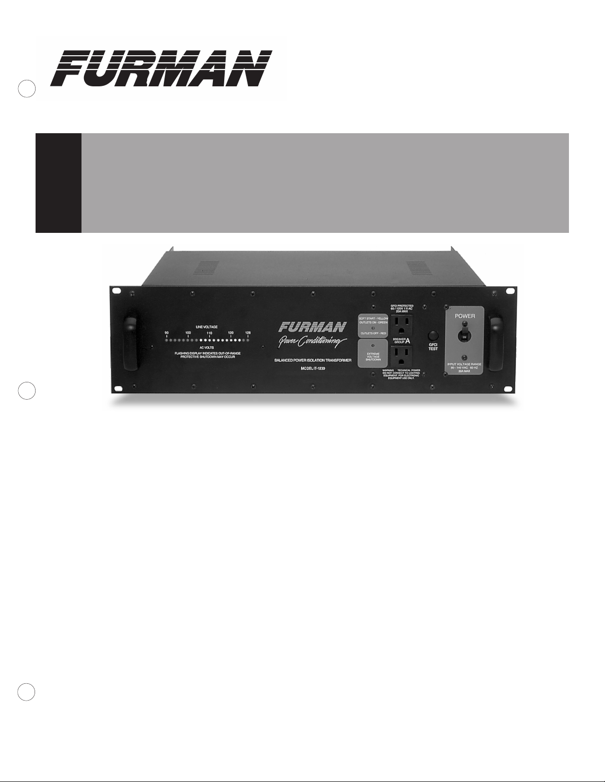
Balanced AC Power Isolation Transformer, 30A
MODEL IT-1230
Owner’s Manual
Introduction
Thank you for your purchase of a Furman IT-1230 30 Amp
Balanced AC Power Isolation Transformer, and congratulations
on your choice. This specially wound and shielded toroidal
isolation transformer is designed specifically to reduce hum pickup
by sensitive equipment when ultra-low-noise is a must.
Features
● Provides precisely balanced AC power for ultra-low-noise
installations
● Typically gives a 16 dB improvement in background noise floor
in systemwide installations
● Toroidal transformer with center-tapped secondary is the most
efficient, compact design, with least magnetic field leakage
● Soft Start circuit prevents turn-on transients and high inrush
currents
● Faraday shield reduces electrostatic coupling between primary
and secondary
● Extreme Voltage Shutdown circuit protects against dangerously
high or low input voltages
● Microprocessor-controlled “smart” AC voltmeter monitors line
voltage, flashes alerts for marginal and extreme conditions
● Provides basic power conditioning functions (spike
suppression, RFI filtering)
● Ground fault interrupter (GFCI) protection
1-9843
Description
Designed for the most critical, ultra-low-noise installations,
the IT-1230 can supply 30 amps of balanced AC power
to a recording studio, video or film production facility, broadcast
station, etc. Its purpose is to drastically reduce hum and buzz
caused both by ground currents from power supply filtering and
by radiation from supply cables into sensitive signal sources like
guitar pickups, tape heads and microphones. Its effect is
startling! It not only dramatically reduces the noise floor but also
noticeably improves dynamic range and sonic clarity.
The IT-1230's heart is a specially wound and shielded
toroidal isolation transformer with a center-tapped secondary. It
is housed in a 3-unit (5.25" high) rack mount chassis. The back
panel provides a 30-amp twistlock inlet and outlet, plus ten 20A
balanced Edison outlets, widely spaced with plenty of clearance
for “wall warts”; the front panel provides two more outlets. An
IT-1230 can be installed in minutes, though you may require some
help in choosing and wiring an appropriate supply cable. The
IT-1230 provides clean and completely safe power—there is no
need to “lift grounds” or compromise the integrity of safety ground
wires to achieve hum reduction.
Special features include an accurate, self-checking AC
voltmeter that not only measures normal voltages, but also flashes
eye-catching special pattern alerts for off-scale but not extreme
conditions (80-90 or 130-140 volts); an Extreme Voltage
Shutdown circuit to cause a protective shutdown if the unit is
exposed to dangerous voltages (like accidental connection to
220V); and a special “Soft Start” circuit to prevent the large inrush surge currents and spikes that would otherwise occur at turnon and turn-off with such a large transformer.
960129-2332
Page 2

Background
In much the same way that balanced audio lines can
reduce the pickup of hum and other types of electromagnetic
interference (EMI), the use of balanced AC power lines in
sensitive audio, video, or computer installations can make an
enormous difference in system noise. But power distribution
in North America, unfortunately, is not balanced. The distribution
standards currently in use were derived from practices established
over a century ago, when electric power use was limited to
lighting and motors—long before any EMI-sensitive applications
existed. The emphasis then was on convenience (from the power
utilities’ standpoint) and safety, but not noise cancellation. The
result was a three-wire distribution scheme in which 120V branch
circuits have a hot wire and a neutral wire, with the neutral tied to
a third wire connected for safety to an earth ground. The third
wire does not carry any current unless there is a short circuit.
This unbalanced scheme causes hum in audio circuits for two
main reasons: First, the current flowing in the hot wire induces
hum in any other nearby wires, which may carry vulnerable lowlevel audio signals. Second, because the impedance of chassis
and cable shielding to ground is not zero, ground current flowing
from power supply capacitors and from EMI pickup causes a voltage drop at 60 Hz and its harmonics which is added to the audio
signals.
With a center-tapped isolation transformer, the AC power
feeding a studio can be balanced at its source. The current-carrying wires then are no longer “hot” (120V) and “neutral” (0V), but
two equal and opposite lines of 60V each (referenced to the safety
ground connected to the center tap), which add to 120V. This
type of power, when run around a room, does not induce hum
into nearby audio wiring, because the two power conductors
induce equal and opposite voltages that cancel each other out.
Similarly, ground currents are all but eliminated by the same
common-mode cancellation effect. No longer is it necessary to
adopt cumbersome and expensive star-ground systems or use
massive bus bars or heavy ground rods. All such systems
are doomed to yield only mediocre results because of the
impossibility of reducing the ground impedance to zero. The
common-mode rejection of a truly balanced AC supply is far
simpler, cheaper, and more effective.
Balanced, or “technical” power, is recognized by the US
National Electrical Code (Article 530) for critical, low noise applications.
Installation
The power source to which the IT-1230 is connected must be
adequate for use at 30 amps. We recommend a 30 amp circuit,
BREAKER
INPUT
80 - 140 VAC
60 HZ 30 AMPS MAX
MADE IN U S A
60 / 120V 1 Ø AC
GFCI PROTECTED
30 AMPS MAX
RISK OF ELECTRIC SHOCK. DO NOT OPEN.
REFER SERVICING TO QUALIFIED SERVICE
PERSONNEL. TO REDUCE THE RISK OF FIRE
OR ELECTRIC SHOCK DO NOT EXPOSE THIS
EQUIPMENT TO RAIN AND MOISTURE.
CAUTION!
60 / 120V 1 Ø AC
GFCI PROTECTED
20 AMPS MAX
RISQUE DE CHOC
ELECTRIQUE — NE PAS OUVRIR
GROUP
WARNING — TECHNICAL POWER
DO NOT CONNECT TO LIGHTING EQUIPMENT.
B
FOR ELECTRONIC EQUIPMENT USE ONLY.
20
20
BREAKER
GROUP
60 / 120V 1 Ø AC
GFCI PROTECTED
20 AMPS MAX
AVIS:
A
(INCLUDES FRONT
PANEL OUTLETS)
IT-1230 Rear View
wired with 10 gauge wiring, if continuous operation near 30 amps
is anticipated. A dedicated (nothing else connected) 30
amp circuit is the minimum acceptable to comply with NEC
requirements. Consult a qualified electrician if in doubt.
The IT-1230 is designed for mounting in a standard 19-inch
rack. Because of its weight, the best position for it is at the bottom
of the rack. Its toroidal transformer minimizes magnetic leakage,
but nevertheless, due to its high capacity, it will radiate an appreciable magnetic field. Therefore, we recommend that it not be
positioned adjacent to sensitive, low level signal processors, especially mic preamps, mixers, tape recorders, etc. Power amps
may be more suitable “rack neighbors.”
The maximum benefit is derived from balanced power when
ALL equipment in an installation is powered with it. Therefore, try
to position the IT-1230 in a central location so its power can be
easily distributed everywhere it’s needed. If the total power consumption of all equipment exceeds 30 amps at 120 volts, delete
high level or mechanical devices first (such as power amps,
etc.). If possible, physically isolate any such equipment that has
to be powered with conventional power through a different circuit,
and route their AC cords away from all other cabling.
The balanced power produced by the IT-1230 is restricted to
use with electronic equipment only. Balanced power may not be
used for lighting equipment, and access must be limited to use by
qualified personnel only.
If you are installing the IT-1230 in a rack that has rear as well
as front mounting rails, you may wish to order adjustable rear
rack ears from Furman. They allow the IT-1230 to be securely
attached both in front and in back. Order model RRM-2.
Operation
Circuit Breaker/Switch: The IT-1230 has just one control:
the large blue switch on the front panel that is both a precision
magnetic circuit breaker and an on-off switch. This breaker will
trip (snap to the “off” position) if the total current drawn through
the IT-1230 exceeds 30 amps. If this occurs, reduce the load by
unplugging some equipment, then flip the switch back to “on.”
LINE VOLTAGE
90
100 110 120 128
AC VOLTS
Mains Voltage Status Voltmeter Reading Outlets
Below 80V Extreme (Shutdown) Meter off—Extreme Voltage LED flashes OFF
80-90 Low Marginal The LED beneath the 90V mark flashes ON
90-104 Low Meter Reads in Low Red ON
106-108 Medium Low Meter Reads in Low Yellow ON
110-120 Normal Meter Reads in Green ON
122-124 Medium High Meter Reads in High Yellow ON
126-128 High Meter Reads in High Red ON
130-140 High Marginal All Meter LEDs Flashing ON
Above 140V Extreme (Shutdown) Meter off—Extreme Voltage LED Flashes OFF
Page 3

Since safety agencies dictate that the 20 amp Edison outlets
be overcurrent limited to 20 amps maximum, they are broken into
two groups: Group A includes the two front panel outlets and two
duplex receptacles on the rear. Group B is comprised of the remaining three duplex Edison outlets. Each group is protected by
its own 20A breaker. The twistlock is capable of a full 30 amps,
however.
Soft Start/Outlets On/Off Indicator: When power is first
applied to the IT-1230, the Soft Start feature is activated,
indicated by a steady yellow color. Soft Start limits the inrush
current to the IT-1230’s transformer, which would otherwise be
excessive. The result is that the IT-1230’s output voltage does
not reach its full level until several seconds have elapsed. When
it has reached its maximum level, the LED color turns to green,
indicating that all outlets are fully powered.
Should the power at the IT-1230's outlets go off for any
reason—either because the power switch is in the “off” position
or because an Extreme Voltage Shutdown has occurred, the LED
will light up red.
Extreme Voltage Shutdown: This LED status indicator is
normally off. It monitors a hazard particularly common in the
entertainment industry: wiring faults—for example, accidental
connection to 220V. The IT-1230 senses voltages that are so high
or low that operation would be impossible (under 80V or over
140V) and shuts the power down before damage can occur. Upon
initially applying power to the IT-1230, this indicator will be lit if
the input is receiving below 80 volts or more than 140 volts, and
power will not be applied to the IT-1230’s outlets. If the unit has
been operating with an acceptable input voltage and then that
voltage goes out of the acceptable range, the IT-1230 will shut off
power to the outlet and this LED will begin flashing.
NOTE: If the mains power is below 80 volts and has caused
the IT-1230 to remove power from its outlets, the IT-1230 will not
restore power to the outlets until the mains voltage is more than
90 volts. If the mains power is above 140 volts and has caused
the IT-1230 to remove power from its outlets, the IT-1230 will not
restore power to the outlets until the mains voltage is less than
130 volts. The reason for this is to prevent the power oscillating
on and off in marginal conditions.
LED Voltmeter: This three-color, 20-LED bargraph is an
accurate, self-checking AC voltmeter that continually measures
the IT-1230’s input voltage. The meter reads from 90 to 128 volts
in two-volt steps. The normal range voltages are indicated in green,
with moderate and extremely high or low voltages in yellow and
red respectively (see chart on the previous page). The voltmeter
provides three special flashing patterns to indicate abnormal power
conditions:
1. If only the single LED located beneath the number 90 on
the voltmeter flashes, voltage at the IT-1230 input is below
90 volts. Power to the IT-1230 outlets will remain on unless
the incoming voltage falls below 80.
2. If all of the LEDs on the voltmeter flash, voltage at the
input is between 130 and 140 volts. Power to the IT-1230’s
outlets will remain on unless the incoming voltage exceeds
140.
3. If none of the LEDs on the voltmeter are lit, and the
Extreme Voltage LED indicator is flashing continuously, then
the IT-1230 has shut down power to its switched outlets due
to input voltage below 80 volts or above 140 volts.
The IT-1230’s voltmeter has a basic accuracy of plus or minus two volts, and extreme cold or heat may cause an additional
one volt of error. Please note that the voltage reading is advisory
only. The IT-1230 does not compensate for high or low line volt-
age. If you frequently move your rack to different locations, derive
power from generators, use long extension cords, travel internationally, or are in an area prone to brownouts, you may benefit
from the use of one of Furman’s AC Line Voltage Regulators.
NOTE: Because the voltmeter reads the input voltage
BEFORE the circuit breaker/on-off switch, its LEDs stay on whenever the IT-1230 is plugged in, even when the power switch is off.
This feature allows you to check voltage before powering up your
equipment. The LEDs are designed for continuous use. They
consume little power, just a few cents worth a month, like a clock.
Ground Fault Current Interrupter (GFCI): The GFCI built
into the IT-1230 is a special kind of circuit breaker that detects an
imbalance in the current flowing in the two hot legs. The “missing”
current is presumed to be flowing through the ground conductor
(the round pin on an AC outlet). Ground current often indicates a
dangerous partial or full short circuit. If an imbalance is detected,
the GFCI will trip the main breaker. To restore operation, correct
the fault and turn the unit on again. 4-6 mA of current is enough to
cause the GFCI to trip; to troubleshoot this type of problem, start
with nothing connected to the IT-1230. Then add each piece of
gear until the GFCI trips. Contact the manufacturer of the suspect
unit for possible solutions.
You should test for proper operation of the GFCI once a month
by pushing the button marked GFCI TEST. If the GFCI is working
properly, this will cause the GFCI TEST main breaker to trip and
to cut off power. You can restore operation after a test by once
again turning the unit ON.
IT-1230 SPECIFICATIONS
Output current: 30 amps (3600 watts at 60/120 V 1 ø AC, 60 Hz)—
Technical power, for electronic equipment (not lighting)
only, per NEC Article 530.
Voltage Ranges: Normal, 90-130; Marginal (flashes alert), 80-90 or
130-140; Extreme (causes shutdown), below 80 or
above 140
Inlet: 30A NEMA L14-30P twistlock inlet connector, rear
Outlets: Rear: 30A NEMA L14-30R twistlock
plus 10 NEMA 5-20 (20A Edison) outlets
Front: 2 NEMA 5-15 outlets suitable for 20A use
Isolation, Input to Output: Breakdown Voltage: 1500V minimum
Leakage current: 40 mA maximum
Capacitance: 300 pf maximum
Turns Ratio: 1:1; windings separated with Faraday shield
Transformer Regulation: (Full load/no load) 3% at full load
Spike Protection Modes: Line to neutral, neutral to ground, line to ground
Spike Clamping Voltage: TVSS rating of 400 volts peak,
L-N, N-G, L-G (tested to UL-1449)
Spike Response time: 1 nanosecond
Maximum surge current: 6,500 amps (8 x 20 mS pulse)
Maximum spike energy: 80 joules per mode, 240 joules total
Noise attenuation: Differential mode: Greater than 40 dB
Transverse mode: Greater than 60 dB
Common mode: Greater than 80 dB, 1 to 200 MHz
Mechanical: Dimensions: 5.25" H x 19" W x 17" D.
Weight: 66 lbs. (30 kg).
Construction: Steel chassis, powder coated;
glass epoxy printed circuit boards
Power Consumption: 8.5 watts for display and control circuits,
independent of actual load
The IT-1230 is manufactured in the United States of America
Page 4

Three Year Limited Warranty
The Furman IT-1230 is warranted against failures due to
defective parts or faulty workmanship for a period of three years
after delivery to the original owner. During this period, Furman
will make any necessary repairs without charge for parts or labor.
Shipping charges to the factory or repair station must be prepaid
by the owner; return shipping charges (via UPS Ground) will be
paid by Furman.
This warranty applies only to the original owner and is not
transferable. Also, it does not apply to repairs done other than by
the Furman factory or Authorized Repair Stations.
This warranty may be cancelled by Furman at its sole discretion if the IT-1230 unit has been subjected to physical abuse or
has been modified in any way without written authorization from
Furman. Furman’s liability under this warranty is limited to repair
or replacement of the defective unit.
Furman will not be responsible for incidental or consequential
damages resulting from the use or misuse of its products. Some
states do not allow the exclusion of incidental or consequential
damages, so the above limitations may not apply to you. This
warranty gives you specific legal rights, and you may also have
other rights which vary from state to state.
Warranty claims should be accompanied by a copy of the original purchase invoice showing the purchase date (if a Warranty
Registration Card was mailed in at the time of purchase, this is
not necessary). Before returning any equipment for repair, please
read the important information on service, which follow.
Service
Before returning any equipment for repair, please be sure
that it is adequately packed and cushioned against damage in
shipment, and that it is insured. We suggest that you save the
original packaging and use it to ship the product for servicing.
Also, please enclose a note giving your name, address, phone
number and a description of the problem.
NOTE: All equipment being returned for repair must have a
Return Authorization (R/A) Number. To get an R/A Number,
please call the Furman Service Department, (707) 763-1010 ext.
40, between 8 am and 5 pm U.S. Pacific Time. Please display
your R/A Number prominently on the front of all packages.
Also Available: Furman IT-1220 and IT-1210
Balanced AC Power Isolation Transformers
For other installations and applications requiring ultra-lownoise performance, consider the Furman IT-1220 and IT-1210.
The IT-1220 (shown below) provides 20 amps of balanced
AC power; the IT-1210 is rated at 10 amps. Both models
include all of the features and performance of the IT-1230.
For more information, please contact us for free data sheets.
Other Furman Products
Power Conditioning & Distribution
PL-8, PL-PLUS Power Conditioner & Light Module, 15A
PL-PRO Power Conditioner & Light Module, 20A
PL-TUNER Power Conditioner/Instrument Tuner, 15A
PLH-15 Power and Light Center, 15A
PM-8 Power Conditioner/Monitor, 15A
PM-PRO Power Conditioner/Monitor, 20A
PS-8, PS-8R Power Conditioner/Sequencer, 15A
PS-PRO Power Conditioner/Sequencer, 20A
PowerLink Remote AC Power Sequence Controller
PowerPort Remote AC Power Controller
MiniPort-15 Power Relay, 15A
MiniPort-20 Power Relay, 20A
MiniPort-15Q Power Relay for Quad Box Mount, 15A
MiniPort-20Q Power Relay for Quad Box Mount, 20A
RS-1 System Control Panel, Maintained Switching
RS-2 System Control Panel, Momentary Switching
AR-1215 AC Line Voltage Regulator, 15A, 120V
AR-2306 AC Line Voltage Regulator, 6A, 230V
AR-1220 AC Line Voltage Regulator, 20A, 120/100V
AR-1230 AC Line Voltage Regulator, 30A, 120/100V
AR-2330 AC Line Voltage Regulator, 30A, 220/230/240V
AR-2330D AC Line Volt. Reg., 30A, 240/230/220V, N. America Use
AR-PRO AC Line Voltage Regulator, 30A, 120V, Worldwide Use
BP-1000 On-Line Uninterruptible Power Supply, 1 KVA
ACD-100 Power Distro, 100A
ASD-120 Sequenced Power Distro, 120A
IT-1210 Isolation Transformer, Balanced AC Power, 10A
IT-1220 Isolation Transformer, Balanced AC Power, 20A
PlugLock™ Locking Outlet Strip
PlugLock-PRO Locking Outlet Strips, Ver tical Mount
WartStrap™ PlugLock WartStrap “Wall Wart” Retention Kit
Please contact us by phone, fax or e-mail for a free copy of our color catalog
Audio Signal Processing
PQ-3 Reissue Parametric Equalizer, Instrument Preamp
PQ-4 Parametric Equalizer, 4 band
Q-151, Q-152 Dual 15-Band Graphic Equalizer
Q-301, Q-302 30-Band Graphic Equalizer
Q-602 Dual 30-Band Graphic Equalizer
Q-541 Quad 5-Band Stereo Graphic EQ
PUNCH-10 Bass Enhancement System
X-312 12 dB Crossover
X-324 2-Way/3-Way 24 dB Crossover
X-424 3-Way/4, 5-Way 24 dB Crossover
X-524 4-Way 24 dB Crossover
C-132 Compressor/Limiter
LC-6 Stereo Compressor/Gate
QN-44 Quad Noise Gate
SP-20A Stereo Half Rack Power Amp, 20W per channel
HA-6A Headphone/Monitor Amp
HR-2 Headphone Passive Remote Box
HDS-6 Headphone Distribution System
HR-6 Personal Headphone Mixer for use with HDS-6
PB-48 48-Point Patch Bay with TRS Connectors
PB-48D 48-Point Patch Bay with TRS and D-Sub Connectors
(Full range of patch cords also available)
MM-3 Three Input Mic Mixer
MM-4A 4 x 1 Rack-Mount Mixer
MM-8A 4 x 2 Rack-Mount Mixer
DJM-6 DJ Production Mixer
DJM-8 DJ Production Mixer
SM-3 Stereo Mixer with Ducking
IP-8 Iso-Patch, Isolated Patch Bay, 8 channel
IP-2, IP-2B Iso-Patch, Dual Isolator, 2 channel
VU-40 System Monitor (Power/VU Meter)
SC-1, 2 Security Covers
.
 Loading...