

Page 1

CONTRACTOR SERIES SmartSequencer™
CN-20MP
Quick Start Guide
Guía de inicio rápido Guide de démarrage rapide
CN-20MP
20 A Maximum
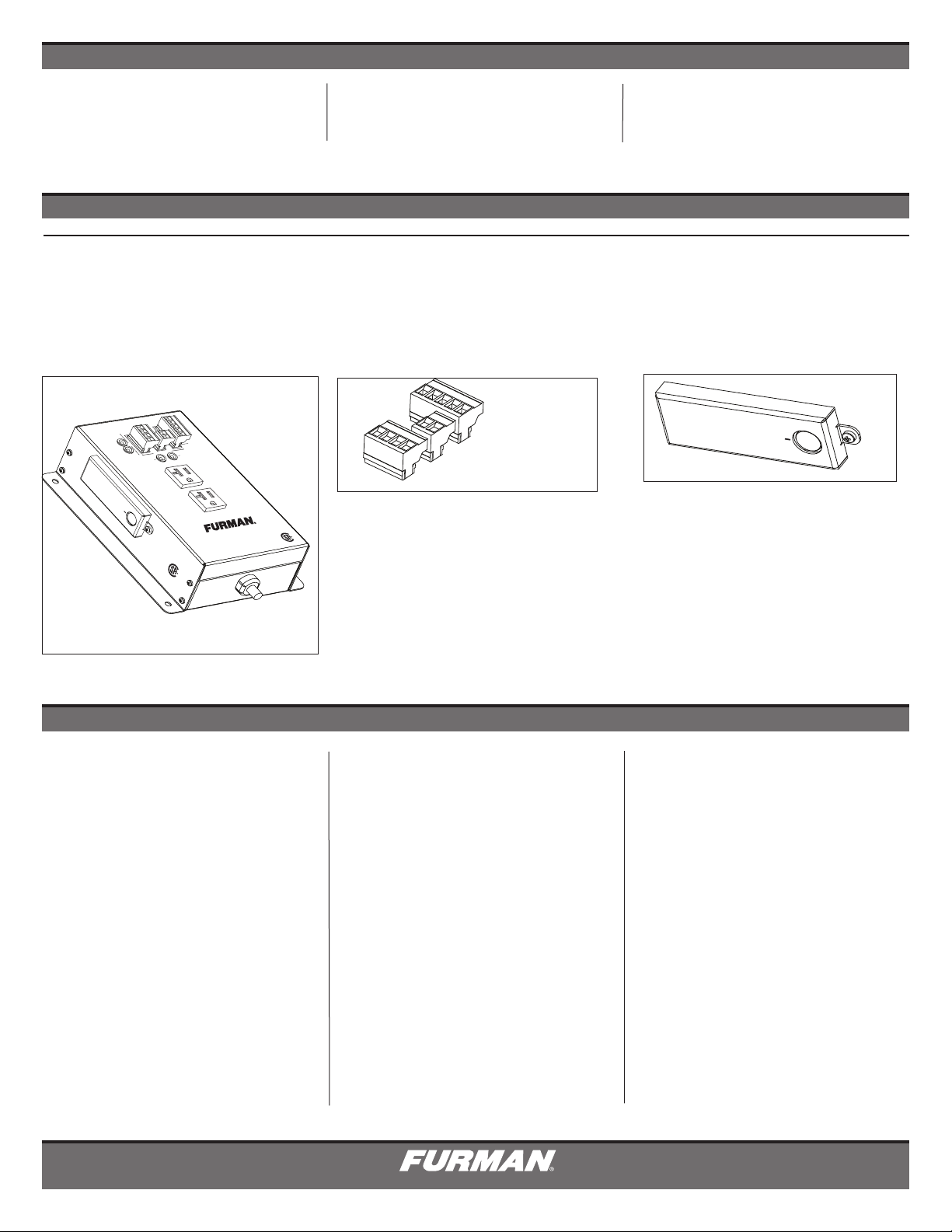
CN-20MP Shown with Phoenix type connectors
removed and security cover attached.
For Full Instructions go to:
Para obtener instrucciones completas, visite:
Pour des instructions complètes allez à:
www.furmancontractor.com
For more information call:
Para más información llame al:
Pour plus de renseignements:
877-486-4738
DQS-00010-A
Page 2
120 VAC
/60/HZ
A MAX.
120 VAC
/60/HZ
A MAX.
C US
20 AMP
MINIPORT
120 VAC, 50/60 Hz
MAX LOAD 20A
POWER
EXTREME VOLTAGE
CLASS 2 WIRING
FORCE
OFF
P
P
S
S
SECONDARY
LINK
SMARTSEQUENCING
OUT
IN
+12V
STAT
REM
GND
DLY OUT
REMOTE
PORT
PRIMARY
LINK
BYPASS
C US
CN-20MP
INTRODUCTION
Congratulations and thank you for choosing a Furman Contractor Series Sequencer / AC Duplex Mini
Port. Key to Furman’s CN Series is SmartSequenc-
BEFORE YOU BEGIN, INSPECT UPON RECEIPT
ing technology, which offers an unprecedented level
of AC control-switching options, streamlining installations from conception to finish. We can assure
you that this Furman Contractor Series Sequencer
/ AC Duplex MiniPort will perform as intended and
provide many years of operation.
Please read IMPORTANT SAFETY INSTRUCTIONS
• No serviceable parts. Please see manual online for details.
• Full instructions at: www.furmancontractor.com/manuals
• Please inspect the Furman Contractor Series unit thoroughly.
• Please contact Furman Customer Service at 707.763.1010, if there is any noticeable damage to product or product does not operate out of box.
• Contents of this package include:
CN-20MP
FORCE
OFF
2. TWO PIN CONNECTOR
1. FOUR PIN CONNECTOR
3 Phoenix Type Connectors
3. FIVE PIN CONNECTOR
Removable Cover Shield
BYPASS
IMPORTANT SAFETY INSTRUCTIONS
1. Please read and follow all instructions.
7. CAUTION: Do not install near any heat sources
such as radiators, heat registers, stoves, or other
2. Keep these instructions.
3. Heed all warnings.
equipment that may produce heat.
8. Protect the power cord from being walked on
or pinched, particularly at plugs, convenience
4. WARNING: This device is intended for
indoor use only. Do not use this device near
receptacles, and the point where they exit the
device.
water. To reduce the risk of fire or electric shock,
do not expose this device to rain or moisture.
9. Please, only use accessories specified by the
manufacturer.
5. CAUTION: Functioning Always On recep-
tacles (depending on switching-sequence mode
utilized). To reduce risk of shock, please disconnect the CN-20MP AC Duplex Miniport from AC
power before servicing any equipment connected
to the CN-20MP.
6. Clean only with dry cloth.
1
10. Refer all servicing to qualified personnel.
Servicing is required when the unit has been
damaged in anyway or fails to operate.
11. WARNING: Do not use power cord as the
main power disconnect. The device is intended
for AC power sequencing.
NOTE:
The box contains no other instructions except
this quick start guide.
Please visit www.furmancontractor.com
or www.furmancontractor.com/manuals
13. Do not defeat the safety purpose of the
polarized plug. A polarized plug has two blades,
with one wider than the other. The wide blade is
provided for your safety. If the provided plug does
not fit into your outlet, consult an electrician for
replacement of the obsolete outlet. (*See next
page for 20A plug)
14. Do not defeat the safety purpose of the
grounding prong. A ground type plug has two
blades and a third grounding prong. The third
prong is provided for your safety. If the provided
plug does not fit into your outlet, consult an electrician for replacement of the obsolete outlet.
15. WARNING: This device must be connected
to an AC outlet with a protective earth ground
connection.
Page 3
120 VAC
/60/HZ
A MAX.
120 VAC
/60/HZ
A MAX.
C US
20 AMP
MINIPORT
120 VAC, 50/60 Hz
MAX LOAD 20A
POWER
EXTREME VOLTAGE
CLASS 2 WIRING
FORCE
OFF
P
P
S
S
SECONDARY
LINK
SMARTSEQUENCING
OUT
IN
+12V
STAT
REM
GND
DLY OUT
REMOTE
PORT
PRIMARY
LINK
BYPASS
C US
CN-20MP
FEATURES
SmartSequencing™ is a command response
non-polarized bidirectional current loop. It is a
technology that allows large complex A/V systems
to be safely power cycled on and off with a simple
key turn or press of a button (when utilized with
the Furman RS-1, RS-2 remote switches or
any Furman Sequencer-Controller-Conditioner).
Detailed information on SmartSequencing™ can
be found at www.furmancontractor.com.
CN-20MP
Indicator Lights
Delay Adjust allows from 0.1 seconds up to 7
minutes (when used in SmartSequence mode)
EVS (switchable) Extreme Voltage Shutdown to
protect against sustained over voltage from wiring
faults
Forced Off immediate shutdown for safety and
fire ordinance compliance.
Phoenix Type Connectors
Legacy Compatible will function via dry contact
maintain or momentary mode closure with any
Legacy Furman MiniPort or Sequencer-Controller.
2 AC Outlets
10 ft. Power Cord
15 Year Limited Product Warranty
See actual warranty documentation online at
www.furmancontractor.com
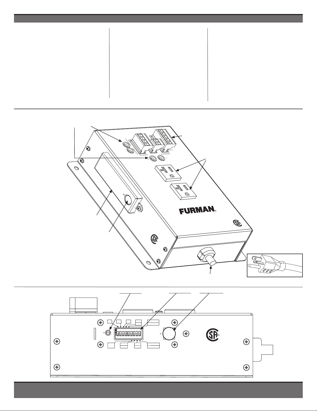
Two AC Outlets (20A)
Removable Cover Shield
Protects DIP Switch and
Potentiometer Settings
Bypass Button for
Forcing Outlet On
10 ft. Power Cord
8
N.O.
N.C.
PRI
SEC
12V ON
5
12V OFF
BYPASS
EVS ON
9
EVS OFF
C US
1M
1
GND
6
ON
2M
2
MOM
7
MNT
4M
3 4
CN-20MP left side view. Cover removed, Potentiometer (delay adjust), DIP Switches, and Bypass Switch for Force On.
DLY
ADJ
20A Cord / Plug
www.furmancontractor.com • 877-486-4738
2
Page 4

FORCE
OFF
SMARTSEQUENCING
+12V
STAT
REM
GND
DLY OUT
REMOTE
PORT
CLASS 2 WIRING
CLASS 2 WIRING
+12V
STAT
REM
GND
DLY OUT
REMOTE
PORT
CLASS 2 WIRING
CLASS 2 WIRING
FRONT AND BOTTOM PANEL FEATURES DESCRIPTIONS
PHOENIX TYPE CONNECTORS
Relay Barrier Strip (2)
FORCE OFF Provides
immediate shutdown by
fire alarm
OUT
P
P
S
S
IN
CLASS 2 WIRING
SmartSequencing
Barrier Strip (1)
Primary poles connect OUT
to Secondary poles of next
SmartSequencing device.
Secondary poles connect IN
from Primary poles of previous
SmartSequencing device.
NOTE: Chain units in series.
CONNECTION STATUS LIGHTS
PRIMARY LINK – Multi-color LED indicates the condition of com-
munication between the Secondary Link and the Primary Link
of the preceding unit.
Unit is communicating through Secondary Link to
GREEN
preceding unit’s Primary Link OUT.
RED
Unit has lost communications through Secondary Link
to preceding unit’s Primary Link OUT.
Please Note: A slow blinking GREEN PRIMARY LINK LED
indicates the unit is configured as the MAIN Primary unit per
DIP Switch 8. (Factory Default)
FORCE
OFF
REMOTE
PORT
CLASS 2 WIRING
PRIMARY
LINK
SECONDARY
LINK
Remote Barrier Strip (3)
+12V - Main DC terminal output for remote triggering
+12V
STAT
REM
GND
DLY OUT
Shown with Phoenix type
connectors removed.
SMARTSEQUENCING
OUT
P
P
S
S
IN
EXTREME VOLTAGE
STAT - DC terminal output for a remote LED indicator (ANODE)
REM - Main terminal input for remote triggering
GND -
Terminal for remote LED status and/or triggering (CATHODE)
DLY OUT - Legacy Miniport compatible Delay On function
(DLY OUT port is neither needed or recommended when utilizing
SmartSequencing products)
FORCE
OFF
CLASS 2 WIRING
REMOTE
PORT
POWER
+12V
STAT
REM
GND
DLY OUT
SECONDARY LINK – Multi-color LED indicates the condition of
communication between the Secondary Link and the Primary
Link of the following unit.
Unit is communicating through Primary Link to
GREEN
following unit’s Secondary Link IN.
OFF
Unit has lost communications through the Primary Link
to following unit’s Secondary Link IN.
Please Note: An unlit SECONDARY LINK LED indicates last
unit in sequencing chain. A single unit will have an unlit
SECONDARY LINK LED
.
POWER PROTECTION INDICATORS
EXTREME VOLTAGE Illuminated RED when an extreme voltage
condition is present (If DIP 9 = ON, all outlets will be powered
off). EVS is activated or disabled by the (DIP 9) setting. EVS
when utilized will automatically reset when the incoming AC
voltage returns to a safe range of operation (90VAC - 130VAC).
POWER Illuminated GREEN indicates when the AC duplex is
powered.
3
BASIC POWER
MANAGEMENT
20 AMP
MINIPORT
20A Plug
120 VAC, 50/60 Hz
MAX LOAD 20A
CN-20MP
10 FT. AC POWER CORD
3/12 AWG, NEMA 5-20P
PLUG
C US
TWO NEMA 5-20R
AC RECEPTACLES
Page 5

1 2 3 4 5 6 7 8 9
ON
C US
LEFT SIDE PANEL FEATURES (SECURITY COVER PLATE REMOVED)
DIP SWITCH MATRIX AND TIME CALIBRATION (diagrams below)
1M = 1 Minute Delay
DIP 1
DIP 2
2M = 2 Minute Delay
4M = 4 Minute Delay
DIP 3
NOTE: DIP 1, 2 & 3 can be summed together up to 7 minutes.
DIP 4
N.O. / N.C. sets Forced Off alarm poles
The out of the box factory setting is “normally open”.
When sequence is “ON”. Switched outlets will be ON
until a dry contact closure is applied across the
FORCE OFF poles.
1
1M
2
2M
DLY
ADJ
GND
6
ON
7
12VDC ON/OFF sets +12V pole in
DIP 5
Remote Mode (DIP 7 set to MNT)
Chooses +12V to REM pole functionality. In default
12V OFF mode, a dry closed contact across +12V to REM
triggers sequencer OFF. In 12V ON mode, a dry closed
contact from +12V to REM triggers sequencer ON.
• 12V OFF = 12V Deactivates
• 12V ON = 12V Activates
GROUND ON / OFF
DIP 6
Activates REM to GND pole functionality.
• REMOTE TO GROUND = ON
4M
3 4
N.O.
N.C.
12V ON
5
12V OFF
BYPASS
MOM
MNT
PRI
8
SEC
EVS ON
9
EVS OFF
Maintained / Momentary
DIP 7
Sets contact closure preference for either
Maintained or Momentary switches.
NOTE: Momentary mode overrides DIP 5 and 6.
DIP 8
PRIMARY / SECONDARY
Delegates unit’s role in command sequence.
EVS AUTO / NO EVS setting
DIP 9
Enables / Disables Extreme Voltage Shutdown.
FACTORY DEFAULT SETTINGS - SET FOR 30 SECOND DELAY
Time Delay Adjustment ranges from 0.0% to 100%.
The percentage is multiplied with the DIP switch selections 1, 2 and 3.
POTENTIOMETER DEFAULT SETTING
- Time Delay Adjustment is set at 12:00
o’clock (50%)
DIP SWITCH DEFAULT SETTING - Switches are factory pre-set as shown below. Switches 1, 4, 8, and 9
are up (ON) position all others are OFF.
ON
DLY
ADJ
NOTE: The DIP switch ON / OFF settings are indicated
as shown below throughout this manual.
ON
www.furmancontractor.com • 877-486-4738
BYPASS BUTTON
Forces the outlet to be ON.
OFF
4
Page 6

SmartSequencer
™
DIAGRAM 1
-
SMALL SMARTSEQUENCING SET-UP
CLASS 2 WIRING
24 AWG RECOMMENDED
Fire ordinances sometime require immediate shut
down, no matter how large or small a sound system.
SmartSequencing provides the solution.
RS-2 Momentary
Remote Switch
CN-2400S
+12
STAT
REM
GND
+12
STAT
REM
GND
P
S
FIRE ALARM (2 POLE)
V S R G D
P S
FORCE OFF
V S R G D
P S
FRONT PANEL DIP SWITCH SET
POWERED ARRAYS
MONITOR SYSTEM
BACK PANEL TERMINALS
CN-20MP
CN-20MP
FORCE
OFF
NO
NC
C
FORCE OFF
DELAY
ADJUST
IMMEDIATE FORCED OFF WITH SHORT
V = VOLTAGE
S = STATUS
R = REMOTE
G = GROUND
D = DELAY
ON
1 2 3 4 5 6 7 8 9
ON
1 2 3 4 5 6 7 8 9
DIP SWITCH SET
DIP SWITCH SET
ON
1 2 3 4 5 6 7 8 9
FOR REFERENCE
ONLY
ABBREVIATED
DESCRIPTIONS
AS SHOWN ON
THE PRODUCT.
NOT FOR
SETTING(S)
INSTRUCTIONS.
GND
ON
MOM
MNT
PRI
SEC
EVS ON
EVS OFF
6
7
8
9
1M
2M
4M
N.O.
N.C.
12V ON
12V OFF
1
2
3 4
5
1 2 3 4 5 6 7 8 9
ON
CN-20MP PRIMARY
CN-2400 replaces Legacy product for
purposes of immediate shutdown.
RS-1 Maintained
Key Switch
+12
STAT
REM
GND
SmartSequencer
™
DIAGRAM 2
-
SMARTSEQUENCING SET-UP - BUDGET
CLASS 2 WIRING
24 AWG RECOMMENDED
CN-20MP
V S R G D
V S R G D
MP-20 (Old)
V S R G D
V S R G D
P S
FORCE OFF
ON
1 2 3 4 5 6 7 8 9
DIP SWITCH SET
MP-20 (Old)
FOR REFERENCE
ONLY
ABBREVIATED
DESCRIPTIONS
AS SHOWN ON
THE PRODUCT.
NOT FOR
SETTING(S)
INSTRUCTIONS.
GND
ON
MOM
MNT
PRI
SEC
EVS ON
EVS OFF
6
7
8
9
1M
2M
4M
N.O.
N.C.
12V ON
12V OFF
1
2
3 4
5
1 2 3 4 5 6 7 8 9
ON
EXAMPLE 1 DIAGRAM - SMALL SmartSequencing SET-UP (Typical)
EXAMPLE 2 DIAGRAM - SMARTSEQUENCING SET-UP - SAMLL LEGACY UPGRADE
When using Legacy Port,
Dip Switch #8 must be in
the up position.
5
Page 7

This upgrade is based upon scenario number 3 in
the ASD-120 manual. The new example substitutes
CN-2400S units at the old miniport locations.
PRIMARY CONTROL AMP RACK
P
S
+12
STAT
START
REM
FORCE ON
FORCE OFF
REM COMM
GND
RLY COMM
F
ASD-120
A
B
C
D
E
CN-2400S
+12
STAT
REM
GND
STAT
REM
GND
(LOCATION ORIGINALLY WAS A MP-20Q)
STAGE MONITOR CIRCUITS
#1 B
WAS MP-20
#2
SmartSequencer
™
DIAGRAM 3
-
LARGE LEGACY UPGRADE
BACK PANEL TERMINALS
ON
1 2 3 4 5 6 7 8 9
DIP SWITCH SET
FORCE OFF
FORCE OFF
RS-1 Maintained
Key Switch
+12
STAT
REM
GND
CLASS 2 WIRING
24 AWG RECOMMENDED
#1 A
CN-20MP
V S R G D
P S
FORCE OFF
ON
1 2 3 4 5 6 7 8 9
DIP SWITCH SET
WAS MP-20
CN-20MP
V S R G D
P S
FORCE OFF
ON
1 2 3 4 5 6 7 8 9
DIP SWITCH SET
FOR REFERENCE
ONLY
ABBREVIATED
DESCRIPTIONS
AS SHOWN ON
THE PRODUCT.
NOT FOR
SETTING(S)
INSTRUCTIONS.
GND
ON
MOM
MNT
PRI
SEC
EVS ON
EVS OFF
6
7
8
9
1M
2M
4M
N.O.
N.C.
12V ON
12V OFF
1
2
3 4
5
1 2 3 4 5 6 7 8 9
ON
P
P
S
S
CN-2400S
+12
STAT
REM
GND
UNIT 3
SECONDARY INTERFACE
NO
NC
C
FORCE OFF
FORCE OFF
P
P
S
S
CN-2400S
+12
STAT
REM
GND
UNIT 2
SECONDARY INTERFACE
NO
NC
C
FORCE OFF
FORCE OFF
FORCE OFF
FORCE OFF
NO
NC
C
ON
1 2 3 4 5 6 7 8 9
SECONDARY DIP SWITCH SET
SYSTEM CONTROLLER
RS-232 PROTOCOL
CN-1800S
+12
STAT
REM
GND
System controllers can interface
with the CN Series sequencers
locally or from the cloud. Yet also
be interrupted by fire alarms.
SmartSequencer
™
DIAGRAM 4
-
LARGE SMART SET-UP PRIMARY INDEPENDENT MULTI-ROOM
COMMON SETTING FOR UNITS (2, 3, 4, 5)
SECONDARY INTERFACE UNITS ABOVE
UNIT 1
PRIMARY INTERFACE
SEPARATE ROOM
P
P
S
S
FIRE ALARM
3 POLE
ON
1 2 3 4 5 6 7 8 9
PRIMARY DIP SWITCH SET
COMMON SETTING FOR UNIT 1
PRIMARY INTERFACE UNIT ABOVE
CLASS 2 WIRING
24 AWG RECOMMENDED
V S R G D
P S
FORCE OFF
CN-20MP
V S R G D
P S
FORCE OFF
UNIT 5
UNIT 4
CN-20MP
SECONDARY
INTERFACE
SECONDARY
INTERFACE
FOR REFERENCE ONLY
ABBREVIATED
DESCRIPTIONS
AS SHOWN ON
THE PRODUCT.
NOT FOR
SETTING(S)
INSTRUCTIONS.
GND
ON
MOM
MNT
PRI
SEC
EVS ON
EVS OFF
6
7
8
9
1M
2M
4M
N.O.
N.C.
12V ON
12V OFF
1
2
3 4
5
1 2 3 4 5 6 7 8 9
ON
EXAMPLE 3 DIAGRAM - LARGE LEGACY UPGRADE
EXAMPLE 4 DIAGRAM - LARGE SET-UP PRIMARY CONTROLLED VIA RS-232
www.furmancontractor.com • 877-486-4738
6
Page 8

SPECIFICATIONS
Maximum AC Current Rating:
• 20 Amps, 120 VAC
AC Cord:
• 3/12 AWG, 10 feet, black, fixed, NEMA 5-20P plug
AC Receptacles:
• AC Outlets: 2 Switched NEMA 5-20R (1 duplex)
Surge/Under-Overvoltage Protection:
• AC Undervoltage Protection: EVS, 77VAC+/-3VAC
• AC Overvoltage Protection: EVS, 145VAC+/-5VAC
• AC Under-Overvoltage Activate/Deactivate Modes: ON or OFF DIP 9 (configurable)
Operating Temperature Range:
• 5C (40F) to 40C (105F) degrees
Humidity Range:
User Interface:
• Front panel diagnostic indicators: Primary link, Secondary link, Power, Extreme Voltage
• Side Panel DIP Switches: Hidden by security cover, 1 Minute Delay,
2 Minute Delay, 4 Minute Delay, Force Off NO/NC, 12V Mode ON/OFF, GND Mode On,
Momentary/Maintained, Primary/Secondary, EVS ON/OFF
• Potentiometer: Side panel, time calibration hidden by security cover, fine tune delay
adjust
Control/Status/Triggering (Front Panel):
• Remote Terminal: +5-30VDC IN, 12VDC (12mA) OUT
• SmartSequencing: Phoenix type 4-Pin Connector, with Screw Terminals, Primary &
Secondary Links (Current Loop - 1000’ nominal)
• Remote Terminal: Phoenix type 5-Pin Connector with Screw Terminals;
+12V, STAT, REM, GND, DLY OUT (Class 2 Wiring)
• Force Off: Phoenix type 2-Pin Connector with Screw Terminals, (Class 2 Wiring)
Power Consumption (No Load): 10 Watts
Safety Compliance:
C US
• <90% rH (Relative Humidity)
Specifications subject to change due to product upgrades and improvements.
WARRANTY INFORMATION
15 YEAR LIMITED PRODUCT WARRANTY*
Furman warrants to the original purchaser of this product for a
period of fifteen (15) years from the date of purchase, that the
unit shall be free of defects in design, material or workmanship, and Furman will repair or replace any defective unit.
Full Warranty and Policy information available at
www.furmancontractor.com
CAUTION! WARRANTY LIMITATION FOR INTERNET PURCHASERS
Furman products purchased through the Internet do not carry a valid
Product Warranty unless purchased from an Authorized Furman
Internet Dealer and the original factory serial numbers are intact
(they must not have been removed, defaced or replaced in any way).
Purchasing from an Authorized Furman Internet Dealer insures that
the product was intended for consumer use, has passed all quality
inspections and is safe. Buying through auction sites or unauthorized
dealers may result in the purchase of salvaged, failed and/or products
not intended for use in the US. In addition, Authorized Furman Internet
dealers have demonstrated sufficient expertise to insure warranty
compliant installations.
For a list of Authorized Furman Internet Dealers
go to www.furmansound.com
7
DQS-00010-A
 Loading...