

Funai TD-5-BN-8481-ZB Service manual
SERVICE MANUAL
Main Section
I Specifications
I Preparation for Servicing
I Adjustment Procedures
I Schematic Diagrams
I CBA’s
I Exploded views
I Parts List
When servicing the deck
mechanism, refer to MK14 Deck
Mechanism Section.
Deck Mechanism Part No.:
N25E1FL
HDD & DVD /
VIDEO CASSETTE RECORDER
TD5B-N8481ZB
PAL

MAIN SECTION
HDD & DVD /
VIDEO CASSETTE RECORDER
TD5B-N8481ZB
Main Section
I Specifications
I Preparation for Servicing
I Adjustment Procedures
I Schematic Diagrams
I CBA
I Exploded Views
I Parts List
TABLE OF CONTENTS
Specifications . . . . . . . . . . . . . . . . . . . . . . . . . . . . . . . . . . . . . . . . . . . . . . . . . . . . . . . . . . . . . . . . . . . . . . . . . 1-1-1
Laser Beam Safety Precautions . . . . . . . . . . . . . . . . . . . . . . . . . . . . . . . . . . . . . . . . . . . . . . . . . . . . . . . . . . . 1-2-1
Important Safety Precautions . . . . . . . . . . . . . . . . . . . . . . . . . . . . . . . . . . . . . . . . . . . . . . . . . . . . . . . . . . . . . 1-3-1
Standard Notes for Servicing . . . . . . . . . . . . . . . . . . . . . . . . . . . . . . . . . . . . . . . . . . . . . . . . . . . . . . . . . . . . . 1-4-1
Handling Precautions for HDD . . . . . . . . . . . . . . . . . . . . . . . . . . . . . . . . . . . . . . . . . . . . . . . . . . . . . . . . . . . . 1-5-1
Preparation for Servicing . . . . . . . . . . . . . . . . . . . . . . . . . . . . . . . . . . . . . . . . . . . . . . . . . . . . . . . . . . . . . . . . 1-6-1
Cabinet Disassembly Instructions. . . . . . . . . . . . . . . . . . . . . . . . . . . . . . . . . . . . . . . . . . . . . . . . . . . . . . . . . . 1-7-1
Electrical Adjustment Instructions . . . . . . . . . . . . . . . . . . . . . . . . . . . . . . . . . . . . . . . . . . . . . . . . . . . . . . . . . . 1-8-1
How to Self-Check and HDD Format . . . . . . . . . . . . . . . . . . . . . . . . . . . . . . . . . . . . . . . . . . . . . . . . . . . . . . . 1-9-1
How to Initialize the HDD & DVD/ VCR. . . . . . . . . . . . . . . . . . . . . . . . . . . . . . . . . . . . . . . . . . . . . . . . . . . . . 1-10-1
Firmware Renewal Mode . . . . . . . . . . . . . . . . . . . . . . . . . . . . . . . . . . . . . . . . . . . . . . . . . . . . . . . . . . . . . . . 1-11-1
Function Indicator Symbols. . . . . . . . . . . . . . . . . . . . . . . . . . . . . . . . . . . . . . . . . . . . . . . . . . . . . . . . . . . . . . 1-12-1
Troubleshooting. . . . . . . . . . . . . . . . . . . . . . . . . . . . . . . . . . . . . . . . . . . . . . . . . . . . . . . . . . . . . . . . . . . . . . . 1-13-1
Block Diagrams . . . . . . . . . . . . . . . . . . . . . . . . . . . . . . . . . . . . . . . . . . . . . . . . . . . . . . . . . . . . . . . . . . . . . . . 1-14-1
Schematic Diagrams / CBA and Test Points . . . . . . . . . . . . . . . . . . . . . . . . . . . . . . . . . . . . . . . . . . . . . . . . . 1-15-1
Waveforms . . . . . . . . . . . . . . . . . . . . . . . . . . . . . . . . . . . . . . . . . . . . . . . . . . . . . . . . . . . . . . . . . . . . . . . . . . 1-16-1
Wiring Diagram . . . . . . . . . . . . . . . . . . . . . . . . . . . . . . . . . . . . . . . . . . . . . . . . . . . . . . . . . . . . . . . . . . . . . . . 1-17-1
IC Pin Function Descriptions. . . . . . . . . . . . . . . . . . . . . . . . . . . . . . . . . . . . . . . . . . . . . . . . . . . . . . . . . . . . . 1-18-1
Lead Identifications . . . . . . . . . . . . . . . . . . . . . . . . . . . . . . . . . . . . . . . . . . . . . . . . . . . . . . . . . . . . . . . . . . . . 1-19-1
Exploded Views. . . . . . . . . . . . . . . . . . . . . . . . . . . . . . . . . . . . . . . . . . . . . . . . . . . . . . . . . . . . . . . . . . . . . . . 1-20-1
Mechanical Parts List . . . . . . . . . . . . . . . . . . . . . . . . . . . . . . . . . . . . . . . . . . . . . . . . . . . . . . . . . . . . . . . . . . 1-21-1
Electrical Parts List . . . . . . . . . . . . . . . . . . . . . . . . . . . . . . . . . . . . . . . . . . . . . . . . . . . . . . . . . . . . . . . . . . . . 1-22-1
Manufactured under license from Dolby Laboratories.
Dolby and the double-D symbol are trademarks of Dolby Laboratories.
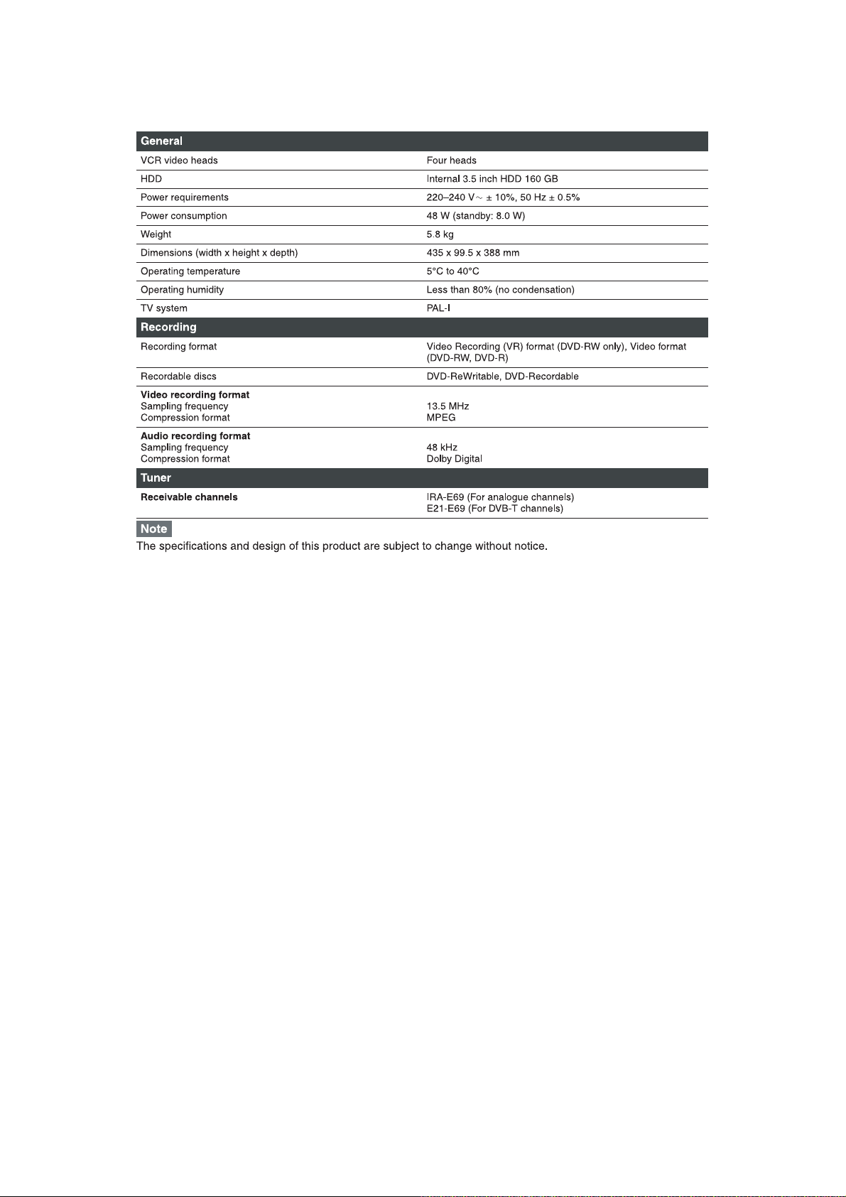
SPECIFICATIONS
1-1-1 E3NF0SP
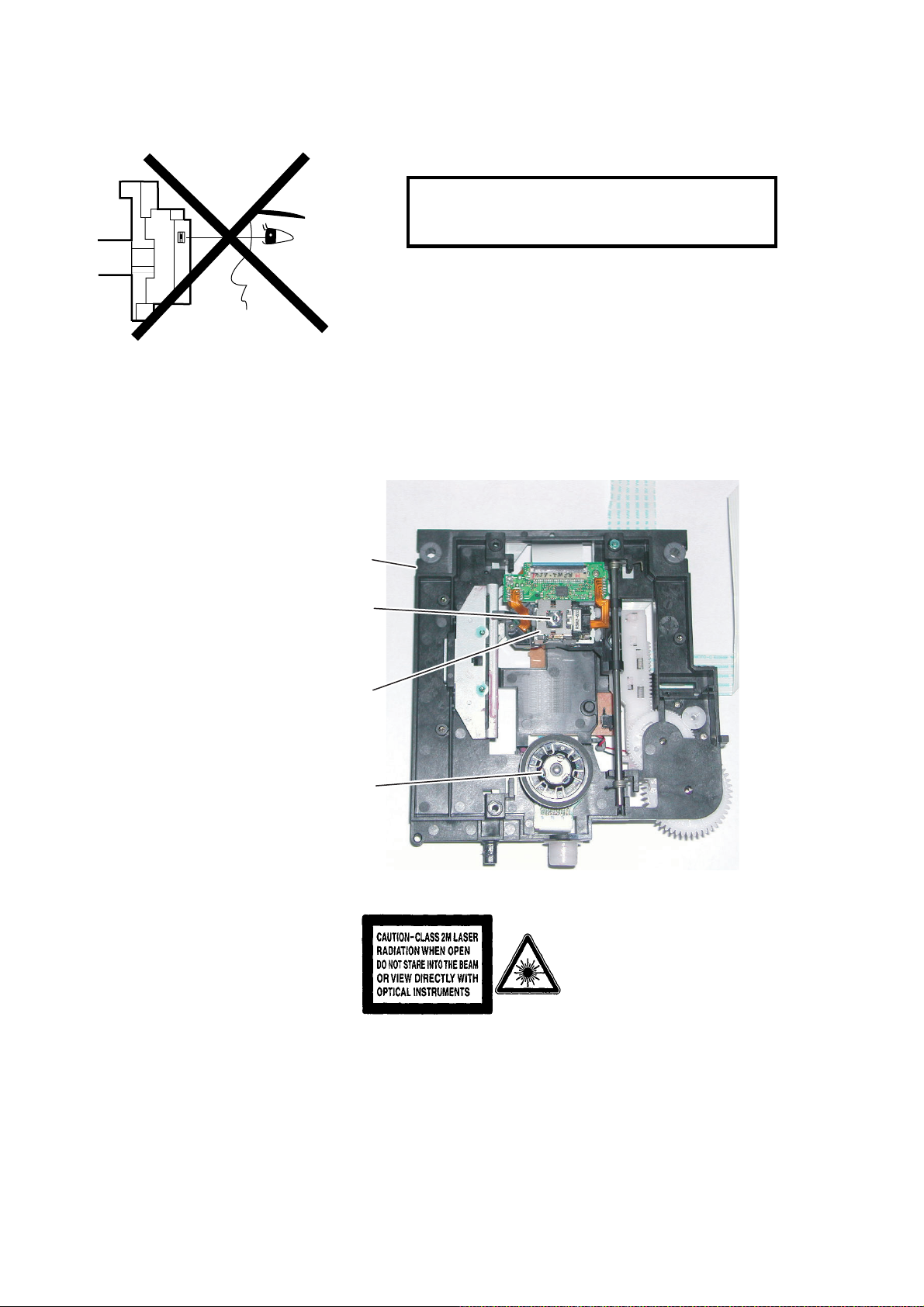
LASER BEAM SAFETY PRECAUTIONS
This DVD player uses a pickup that emits a laser beam.
Do not look directly at the laser beam coming
from the pickup or allow it to strike against your
skin.
The laser beam is emitted from the location shown in the figure. When checking the laser diode, be sure to keep
your eyes at least 30 cm away from the pickup lens when the diode is turned on. Do not look directly at the laser
beam.
CAUTION: Use of controls and adjustments, or doing procedures other than those specified herein, may result in
hazardous radiation exposure.
Drive Mechanism Assembly
Laser Beam Radiation
Laser Pickup
Turntable
Location: Inside Top of DVD mechanism.
1-2-1 TD5PLSP

IMPORTANT SAFETY PRECAUTIONS
Product Safety Notice
Some electrical and mechanical parts have special
safety-related characteristics which are often not evident from visual inspection, nor can the protection
they give necessarily be obtained by replacing them
with components rated for higher voltage, wattage,
etc. Parts that have special safety characteristics are
identified by a ! on schematics and in parts lists. Use
of a substitute replacement that does not have the
same safety characteristics as the recommended
replacement part might create shock, fire, and/or other
hazards. The Product’s Safety is under review continuously and new instructions are issued whenever
appropriate. Prior to shipment from the factory, our
products are carefully inspected to confirm with the
recognized product safety and electrical codes of the
countries in which they are to be sold. However, in
order to maintain such compliance, it is equally important to implement the following precautions when a set
is being serviced.
Precautions during Servicing
A. Parts identified by the ! symbol are critical for
safety. Replace only with part number specified.
B. In addition to safety, other parts and assemblies
are specified for conformance with regulations
applying to spurious radiation. These must also be
replaced only with specified replacements.
Examples: RF converters, RF cables, noise blocking capacitors, and noise blocking filters, etc.
C. Use specified internal wiring. Note especially:
1)Wires covered with PVC tubing
2)Double insulated wires
3)High voltage leads
D. Use specified insulating materials for hazardous
live parts. Note especially:
1)Insulation tape
2)PVC tubing
3)Spacers
4)Insulators for transistors
E. When replacing AC primary side components
(transformers, power cord, etc.), wrap ends of
wires securely about the terminals before soldering.
F. Observe that the wires do not contact heat produc-
ing parts (heatsinks, oxide metal film resistors, fusible resistors, etc.).
G. Check that replaced wires do not contact sharp
edges or pointed parts.
H. When a power cord has been replaced, check that
5 - 6 kg of force in any direction will not loosen it.
I. Also check areas surrounding repaired locations.
J. Be careful that foreign objects (screws, solder
droplets, etc.) do not remain inside the set.
K. When connecting or disconnecting the internal
connectors, first, disconnect the AC plug from the
AC outlet.
L. Be sure to confirm the FAN motor has completely
stopped when disconnecting the AC cord for termination processing is activated during inner P-on
immediately after turning Power off.
1-3-1 DVDP_ISPT
Safety Check after Servicing
Examine the area surrounding the repaired location
for damage or deterioration. Observe that screws,
parts, and wires have been returned to their original
positions. Afterwards, do the following tests and confirm the specified values to verify compliance with
safety standards.
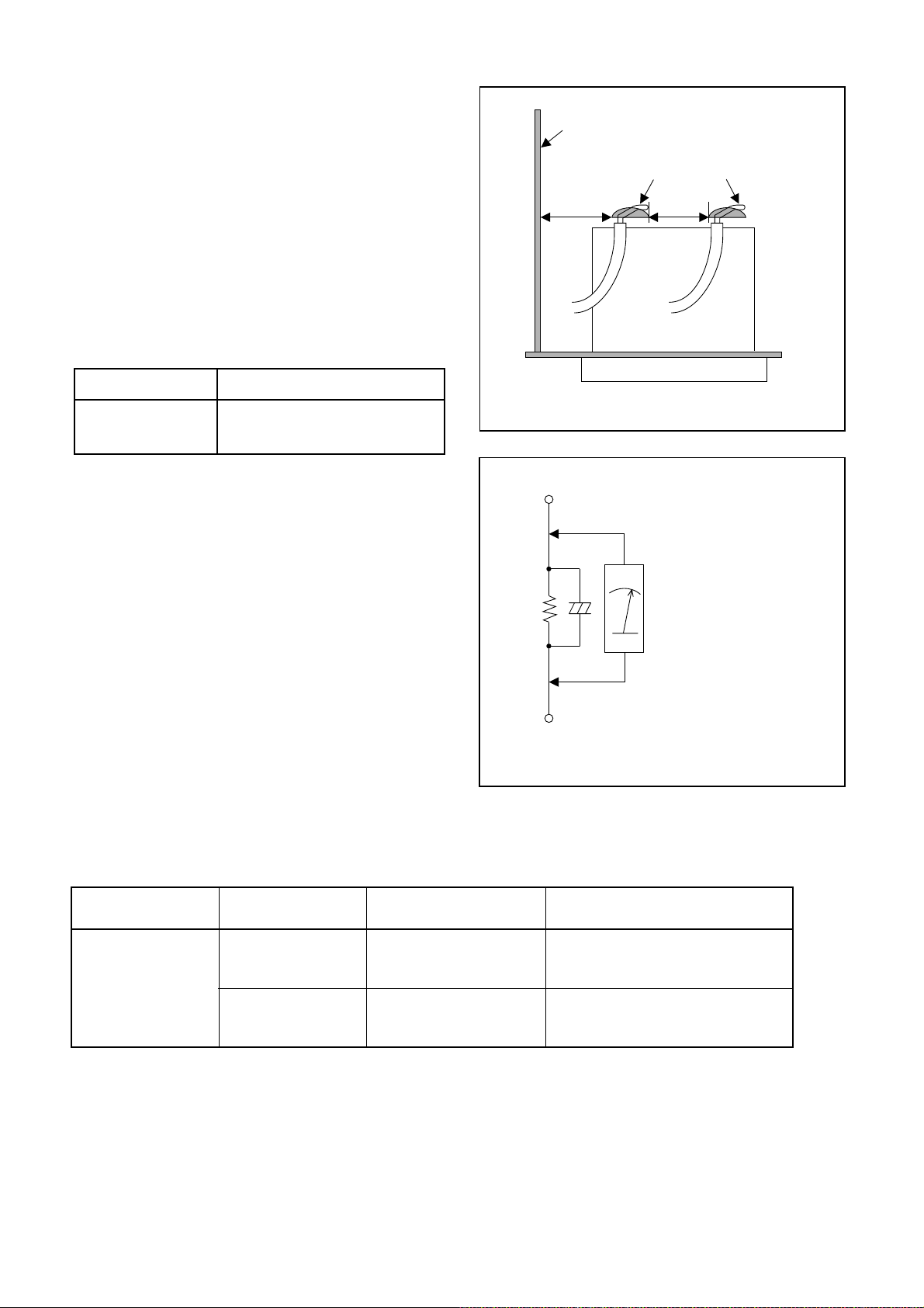
1. Clearance Distance
When replacing primary circuit components, confirm
specified clearance distance (d) and (d’) between soldered terminals, and between terminals and surrounding metallic parts. (See Fig. 1)
Table 1 : Ratings for selected area
AC Line Voltage Clearance Distance (d), (d’)
230 V
Note: This table is unofficial and for reference only.
Be sure to confirm the precise values.
2. Leakage Current Test
≥ 3.2 mm(d)
≥ 6.0 mm(d’)
Chassis or Secondary Conductor
Primary Circuit
d' d
Fig. 1
Exposed Accessible Part
Confirm the specified (or lower) leakage current
between B (earth ground, power cord plug prongs)
and externally exposed accessible parts (RF terminals, antenna terminals, video and audio input and
output terminals, microphone jacks, earphone jacks,
etc.) is lower than or equal to the specified value in the
table below.
Measuring Method (Power ON) :
Insert load Z between B (earth ground, power cord
plug prongs) and exposed accessible parts. Use an
AC voltmeter to measure across the terminals of load
Z. See Fig. 2 and the following table.
Table 2: Leakage current ratings for selected areas
AC Line Voltage Load Z Leakage Current (i)
230 V
2kΩ RES.
Connected in
parallel
50kΩ RES.
Connected in
parallel
i≤0.7mA AC Peak
i≤2mA DC
i≤0.7mA AC Peak
i≤2mA DC
Z
One side of
B
Power Cord Plug Prongs
One side of power cord plug
AC Voltmeter
(High Impedance)
prongs (B) to:
RF or
Antenna terminals
A/V Input, Output
Fig. 2
Note: This table is unofficial and for reference only. Be sure to confirm the precise values.
1-3-2 DVDP_ISPT
STANDARD NOTES FOR SERVICING
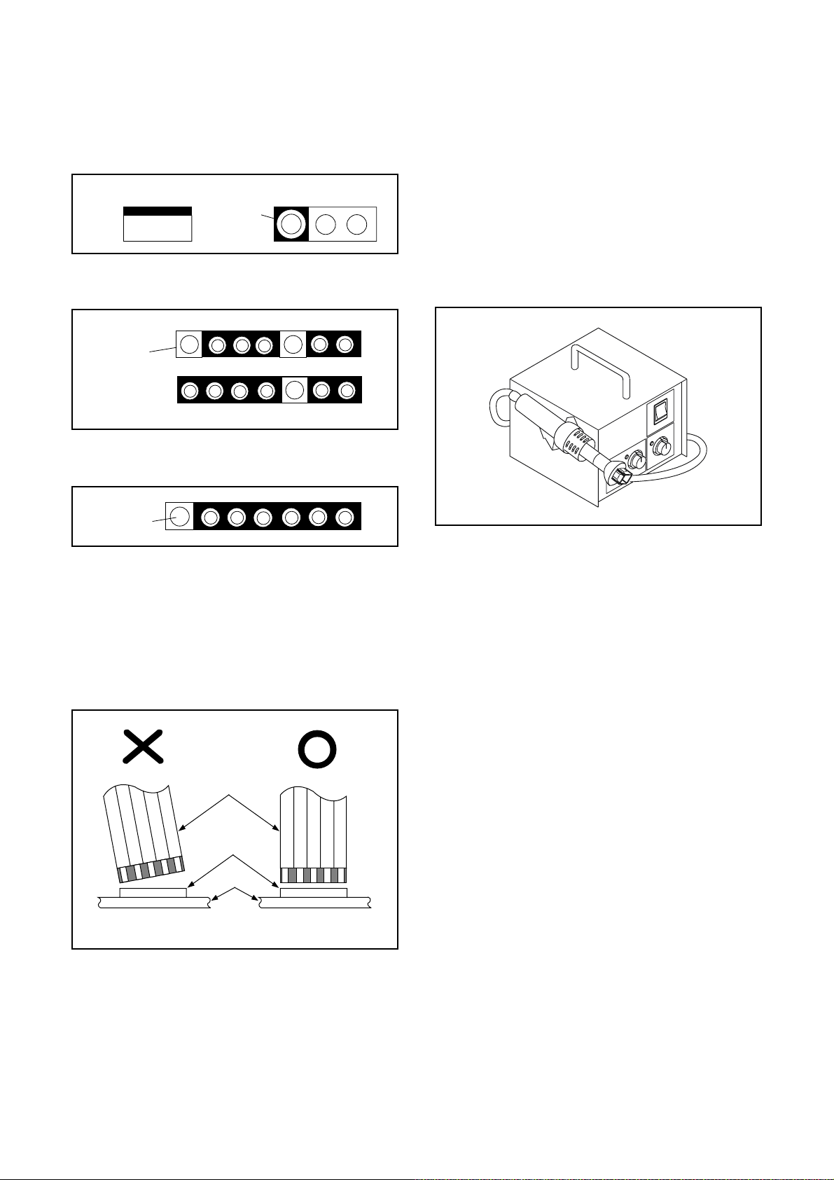
Circuit Board Indications
1. The output pin of the 3 pin Regulator ICs is
indicated as shown.
Top View
Out
2. For other ICs, pin 1 and every fifth pin are
indicated as shown.
Pin 1
3. The 1st pin of every male connector is indicated as
shown.
Pin 1
Input
In
Bottom View
5
10
Pb (Lead) Free Solder
When soldering, be sure to use the Pb free solder.
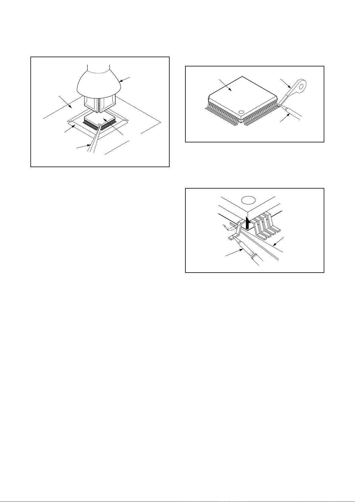
How to Remove / Install Flat Pack-IC
1. Removal
With Hot-Air Flat Pack-IC Desoldering Machine:
1. Prepare the hot-air flat pack-IC desoldering
machine, then apply hot air to the Flat Pack-IC
(about 5 to 6 seconds). (Fig. S-1-1)
Fig. S-1-1
Instructions for Connectors
1. When you connect or disconnect the FFC (Flexible
Foil Connector) cable, be sure to first disconnect
the AC cord.
2. FFC (Flexible Foil Connector) cable should be
inserted parallel into the connector, not at an
angle.
FFC Cable
Connector
CBA
* Be careful to avoid a short circuit.
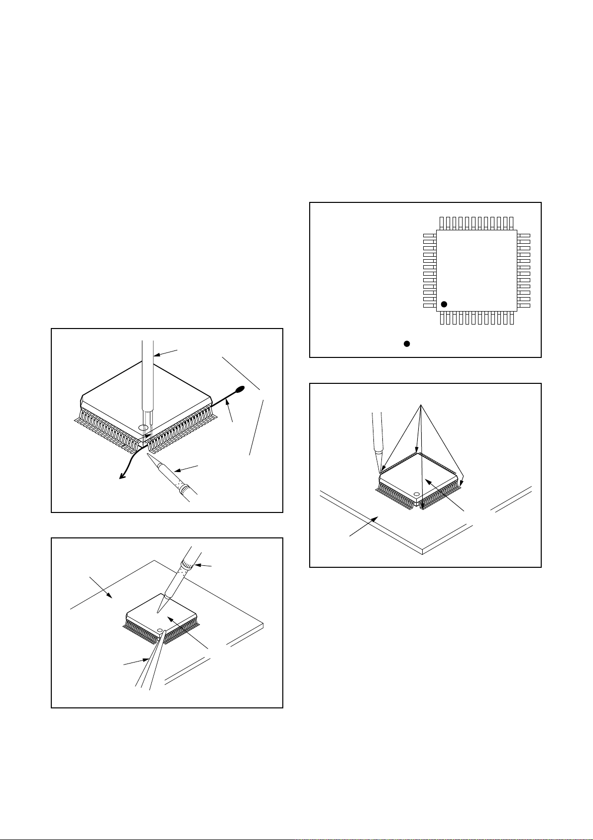
2. Remove the flat pack-IC with tweezers while
applying the hot air.
3. Bottom of the flat pack-IC is fixed with glue to the
CBA; when removing entire flat pack-IC, first apply
soldering iron to center of the flat pack-IC and heat
up. Then remove (glue will be melted). (Fig. S-1-6)
4. Release the flat pack-IC from the CBA using
tweezers. (Fig. S-1-6)
CAUTION:
1. The Flat Pack-IC shape may differ by models. Use
an appropriate hot-air flat pack-IC desoldering
machine, whose shape matches that of the Flat
Pack-IC.
2. Do not supply hot air to the chip parts around the
flat pack-IC for over 6 seconds because damage
to the chip parts may occur. Put masking tape
around the flat pack-IC to protect other parts from
damage. (Fig. S-1-2)
1-4-1 DVDP_SN
3. The flat pack-IC on the CBA is affixed with glue, so
be careful not to break or damage the foil of each
pin or the solder lands under the IC when
removing it.
With Soldering Iron:
1. Using desoldering braid, remove the solder from
all pins of the flat pack-IC. When you use solder
flux which is applied to all pins of the flat pack-IC,
you can remove it easily. (Fig. S-1-3)
CBA
Masking
Tape
Tweezers
Hot-air
Flat Pack-IC
Desoldering
Machine
Flat Pack-IC
Fig. S-1-2
Flat Pack-IC
Desoldering Braid
Soldering Iron
Fig. S-1-3
2. Lift each lead of the flat pack-IC upward one by
one, using a sharp pin or wire to which solder will
not adhere (iron wire). When heating the pins, use
a fine tip soldering iron or a hot air desoldering
machine. (Fig. S-1-4)
Sharp
Pin
Fine Tip
Soldering Iron
3. Bottom of the flat pack-IC is fixed with glue to the
CBA; when removing entire flat pack-IC, first apply
soldering iron to center of the flat pack-IC and heat
up. Then remove (glue will be melted). (Fig. S-1-6)
4. Release the flat pack-IC from the CBA using
tweezers. (Fig. S-1-6)
Fig. S-1-4
1-4-2 DVDP_SN
With Iron Wire:
1. Using desoldering braid, remove the solder from
all pins of the flat pack-IC. When you use solder
flux which is applied to all pins of the flat pack-IC,
you can remove it easily. (Fig. S-1-3)
2. Affix the wire to a workbench or solid mounting
point, as shown in Fig. S-1-5.
3. While heating the pins using a fine tip soldering
iron or hot air blower, pull up the wire as the solder
melts so as to lift the IC leads from the CBA
contact pads as shown in Fig. S-1-5.
4. Bottom of the flat pack-IC is fixed with glue to the
CBA; when removing entire flat pack-IC, first apply
soldering iron to center of the flat pack-IC and heat
up. Then remove (glue will be melted). (Fig. S-1-6)
5. Release the flat pack-IC from the CBA using
tweezers. (Fig. S-1-6)
Note: When using a soldering iron, care must be
taken to ensure that the flat pack-IC is not
being held by glue. When the flat pack-IC is
removed from the CBA, handle it gently
because it may be damaged if force is applied.
Hot Air Blower
2. Installation
1. Using desoldering braid, remove the solder from
the foil of each pin of the flat pack-IC on the CBA
so you can install a replacement flat pack-IC more
easily.
2. The “●” mark on the flat pack-IC indicates pin 1.
(See Fig. S-1-7.) Be sure this mark matches the 1
on the PCB when positioning for installation. Then
presolder the four corners of the flat pack-IC. (See
Fig. S-1-8.)
3. Solder all pins of the flat pack-IC. Be sure that
none of the pins have solder bridges.
Example :
Pin 1 of the Flat Pack-IC
is indicated by a " " mark.
Fig. S-1-7
To Solid
Mounting Point
CBA
Tweezers
Iron Wire
Soldering Iron
Fig. S-1-5
Fine Tip
Soldering Iron
Flat Pack-IC
or
Presolder
Flat Pack-IC
CBA
Fig. S-1-8
Fig. S-1-6
1-4-3 DVDP_SN
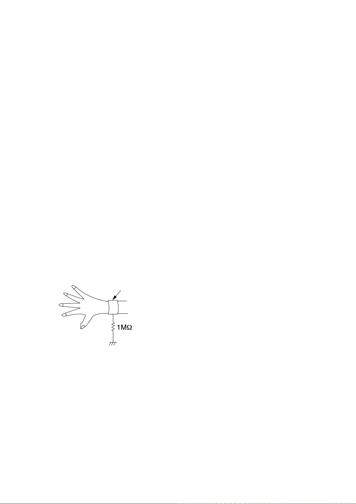
Instructions for Handling Semiconductors
Electrostatic breakdown of the semi-conductors may
occur due to a potential difference caused by
electrostatic charge during unpacking or repair work.
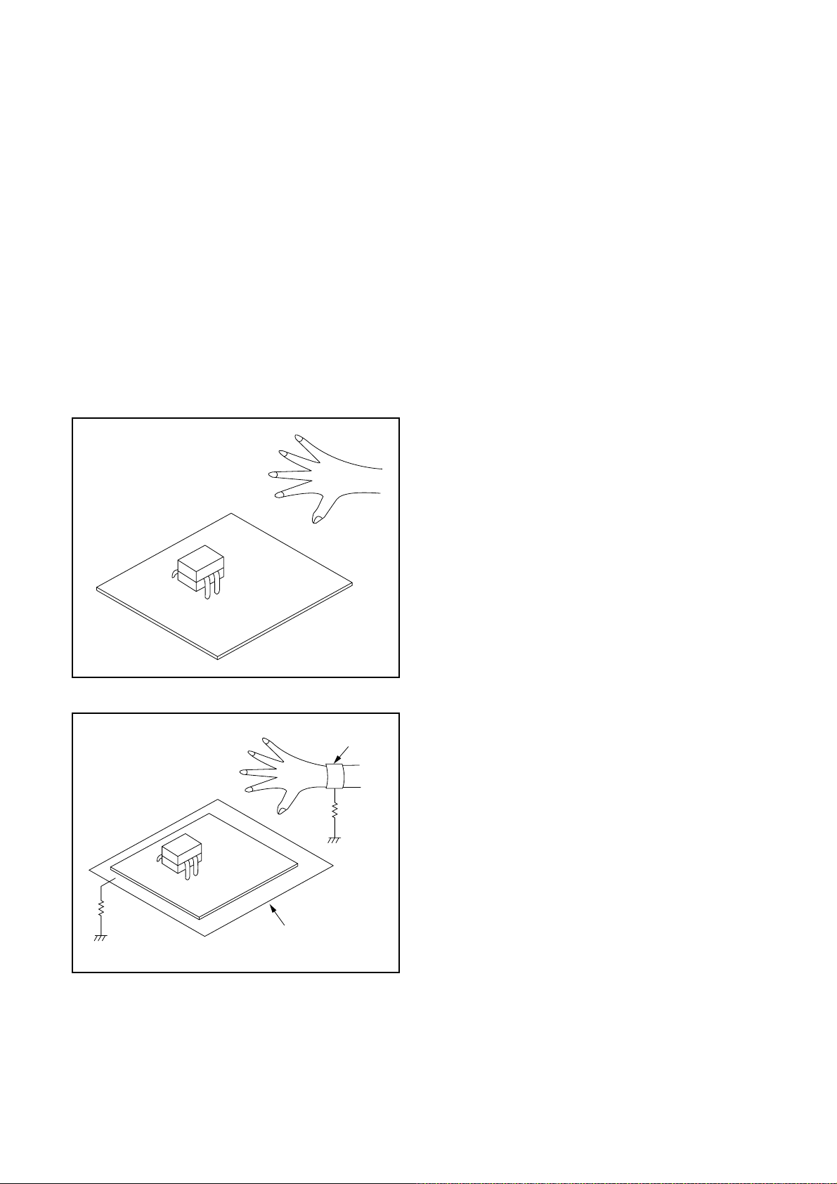
1. Ground for Human Body
Be sure to wear a grounding band (1 MΩ) that is
properly grounded to remove any static electricity that
may be charged on the body.
2. Ground for Workbench
Be sure to place a conductive sheet or copper plate
with proper grounding (1 MΩ) on the workbench or
other surface, where the semi-conductors are to be
placed. Because the static electricity charge on
clothing will not escape through the body grounding
band, be careful to avoid contacting semi-conductors
with your clothing.
<Incorrect>
<Correct>
1MΩ
CBA
Grounding Band
1MΩ
CBA
Conductive Sheet or
Copper Plate
1-4-4 DVDP_SN
HANDLING PRECAUTIONS FOR HDD
CAUTION:
1. SHOCK
a. Exposing HDD to shock may be the biggest
damaging factor. Please note that HDD is easily
damaged even if dropped from any height. Be sure
to place HDD on a shock-absorbent mat. Also, be
careful when transporting HDD.
b. Be careful not to subject HDD to any shock when
tightening screws for HDD replacement.
(Tighten screws manually, not with an electric
driver.)
2. MOISTURE
a. Moisture may also be a damaging factor. HDD is
semiclosed style. Sudden changes in ambient
temperature may cause moisture to form. Monitor
temperature and do not allow moisture to form on
the media surface. Also, when opening HDD
package, do so only after package is at ambient
temperature.
b. After replacing HDD, leave it to reach room
temperature (about 2 hours) for preventing dew
internal condensation, and then work necessary
task such as operation check.
4. OTHERS
a. Be careful so as not to do the followings.
Otherwise, HDD might be damaged.
- DO NOT disassemble HDD.
- When handling HDD, be sure to hold both sides
securely.
b. HDD should be stored, packed in the protective
bag, in suitable surroundings (i.e., no extreme
changes in temperature to avoid condensation).
c. When transporting HDD, be sure to use the
exclusive packing case (the replacement HDD
carton).
d. Do not stack HDDs.
e. Do not place vertically because HDD is unstable
and easy to fall.
3. STATIC ELECTRICITY
a. After removing HDD or taking replacement HDD
out of the protective bag (the replacement HDD is
packed in a protective bag), place HDD on a
conductive surface. A grounding band should be
worn when handling.
Grounding Band
Both the conductive surface and grounding band
should be grounded.
b. Make sure that HDD is placed on main unit
completely and then let go of it, when assembling.
c. Do not put HDD on a packing bag. (for preventing
electrostatic damage)
1-5-1 DHD_SN
PREPARATION FOR SERVICING
How to Enter the Service Mode
About Optical Sensors
Caution:
An optical sensor system is used for the Tape Start
and End Sensors on this equipment. Carefully read
and follow the instructions below. Otherwise the unit
may operate erratically.
What to do for preparation
Insert a tape into the Deck Mechanism Assembly and
press [PLAY](VCR) button. The tape will be loaded
into the Deck Mechanism Assembly. Make sure the
power is on, connect J917 (S-INH) to GND. This will
stop the function of Tape Start Sensor, Tape End Sensor and Reel Sensors. (If these TPs are connected
before plugging in the unit, the function of the sensors
will stay valid.) See Fig. 1.
Q503
J917 (S-INH)
Note: Because the Tape End Sensors are inactive, do
not run a tape all the way to the start or the end of the
tape to avoid tape damage.
Q504
Fig. 1
1-6-1 E3NG0PFS
CABINET DISASSEMBLY INSTRUCTIONS
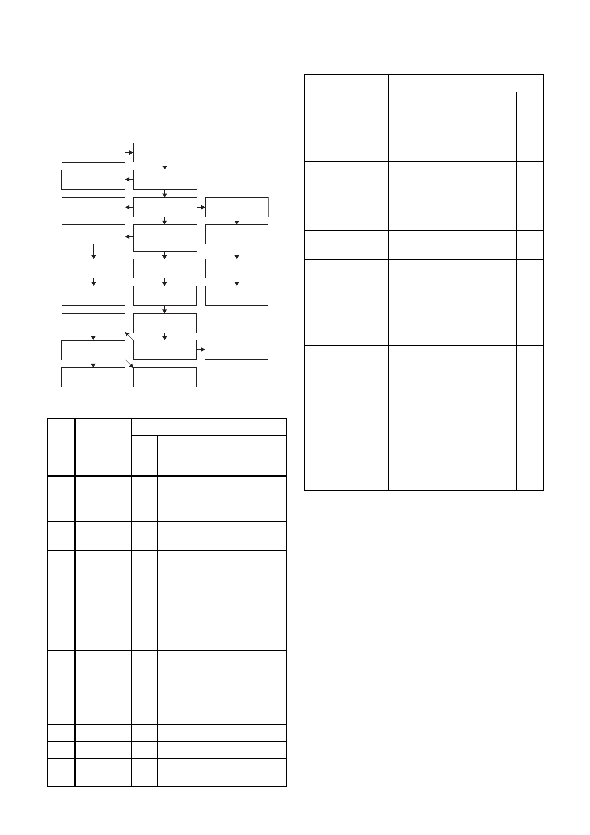
1. Disassembly Flowchart
This flowchart indicates the disassembly steps to gain
access to item(s) to be serviced. When reassembling,
follow the steps in reverse order. Bend, route, and
dress the cables as they were originally.
[1] Top Cover
[22] Front
Bracket R
[23] Bracket R
[13] Power
Supply CBA
[14] SW CBA
[15] Front Jack
CBA
[17] Deck
Assembly
[18] AV CBA
[19] DTV Module
CBA Unit
[2] Front
Assembly
[3] Front
Bracket
[4] HDD
Assembly
[5] DVD Mechanism
& DVD/HDD Main
CBA Assembly
[10] Fan Holder
[11] Motor DC
Fan
[12] Panel Rear
[16] VCR
Chassis Unit
[21] Deck
Pedestal
[6] HDD
Bracket
[7] HDD Unit
[8] HDD
Support
[9] ATA CBA
[20] Power SW
CBA
2. Disassembly Method
ID/
LOC.
No.
PART
Fig.
No.
[1] Top Cover D1 7(S-1) ---
Front
[2]
[3]
[4]
Assembly
Front
Bracket
HDD
Assembly
D2 (S-2), *5(L-1), *3(L-2) 1
D2
D3
DVD
Mechanism
& DVD/
[5]
HDD Main
D3
CBA
Assembly
HDD
[6]
Bracket
D4 4(S-12) ---
[7] HDD Unit D4 4(S-13), HDD Rubber 2
REMOVAL
REMOVE/*UNHOOK/
UNLOCK/RELEASE/
UNPLUG/DESOLDER
(S-3), 3(S-4), Front
Support
(S-5), 3(S-6), *CN652,
Connector
(S-7), 2(S-8), 2(S-9),
2(S-10), *CN101,
*CN502, *CN701,
Dust Cover, Hook,
Mecha Earth Plate
Note
---
---
2
ID/
LOC.
PAR T
No.
[12] Panel Rear D5
Power
[13]
Supply
CBA
REMOVE/*UNHOOK/
Fig.
UNLOCK/RELEASE/
No.
UNPLUG/DESOLDER
2(S-16), 2(S-17),
2(S-18)
(S-19), 3(S-20)
(S-21), *CN1503, FFC
D6
Guide, Chassis Earth
Plate
Note
---
---
[14] SW CBA D6 (S-22), Desolder ---
REMOVAL
Front Jack
[15]
[16]
[17]
CBA
VCR
Chassis
Unit
Deck
Assembly
D6 2(S-23), *CN3011 ---
5(S-24), 4(S-25),
D7
(S-26)
(S-27), (S-28),
D8
Desolder
---
[18] AV CBA D8 ---------- ---
DTV
[19]
Module
D8 Desolder ---
CBA Unit
[20]
[21]
[22]
Power SW
CBA
Deck
Pedestal
Front
Bracket R
D8 Desolder ---
D9 7(S-29) ---
D9 (S-30) ---
[23] Bracket R D9 2(S-31) ---
↓
(1)
↓
(2)
↓
(3)
↓
(4)
(5)
Note:
(1): Identification (location) No. of parts in the figures
(2): Name of the part
(3): Figure Number for reference
(4): Identification of parts to be removed, unhooked,
unlocked, released, unplugged, unclamped, or
desoldered.
P=Spring, L=Locking Tab, S=Screw,
CN=Connector
*=Unhook, Unlock, Release, Unplug, or Desolder
e.g. 6(S-1) = six Screws (S-1),
5(L-1) = five Locking Tabs (L-1)
(5): Refer to “Reference Notes.”
3
4
↓
HDD
[8]
Support
D4 ---------- ---
[9] ATA CBA D4 *CN3001, *CN3002 ---
[10] Fan Holder D5 2(S-14), *CN1002 ---
Motor DC
[11]
Fan
D5 2(S-15) ---
1-7-1 E3NF0DC
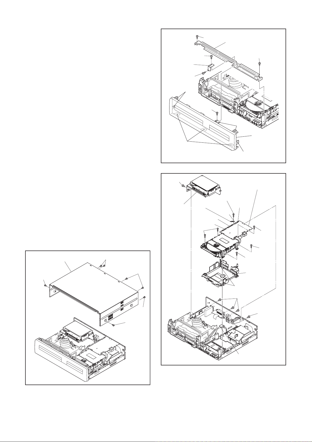
Reference Notes
1. Locking Tabs (L-1) and (L-2) are fragile. Be careful
not to break them.
1-1. Remove Screw (S-2).
1-2. Release five Locking Tabs (L-1).
1-3. Release three Locking Tabs (L-2) and
remove the Front Assembly.
2. Do not replace the DVD Mechanism or the DVD/
HDD Main CBA Assembly separately, when
replacing the DVD Mechanism & DVD/HDD Main
CBA Assembly. Order the new DVD Mechanism &
DVD/HDD Main CBA Assembly.
2-1. Whenever you have replaced the HDD unit,
format the HDD unit. To format the HDD unit,
perform the following.To put the HDD & DVD/
VCR into the HDD mode, press the [HDD]
button on the remote control unit.
2-2. To put the HDD & DVD/VCR into the self-
check mode, after pressing [VARIABLE
SKIP] button, press the [0], [7], and [9]
buttons on the remote control in that order
within three seconds.
2-3. Press [ENTER/OK] button. The HDD & DVD/
VCR is formatted and the power is turned off
automatically after two seconds.
3. When reassembling, solder wire jumpers as
shown in Fig. D8.
4. Before installing the Deck Assembly, be sure to
place the pin of LD-SW on the AV CBA as shown
in Fig. D8. Then, install the Deck Assembly while
aligning the hole of Cam Gear with the pin of LDSW, the shaft of Cam Gear with the hole of LD-SW
as shown in Fig. D8.
Front
Support
(S-4)
(L-1)
(L-2)
(S-5)
[4] HDD
Assembly
(S-4)
(S-4)
(S-2)
Mecha Earth
Plate
CN701
CN101
(S-10)
[3] Front Bracket
(S-3)
(L-1)
[2] Front
Assembly
(L-1)
Fig. D2
[5] DVD Mechanism &
DVD/HDD Main CBA
Assembly
(S-8)
CN502
CN652
(S-8)
(S-9)
[1] Top Cover
(S-1)
(S-1)
(S-1)
Fig. D1
(S-1)
(S-1)
(S-9)
Dust Cover
Hook
(S-6)
Connector
(S-7)
Fig. D3
1-7-2 E3NF0DC
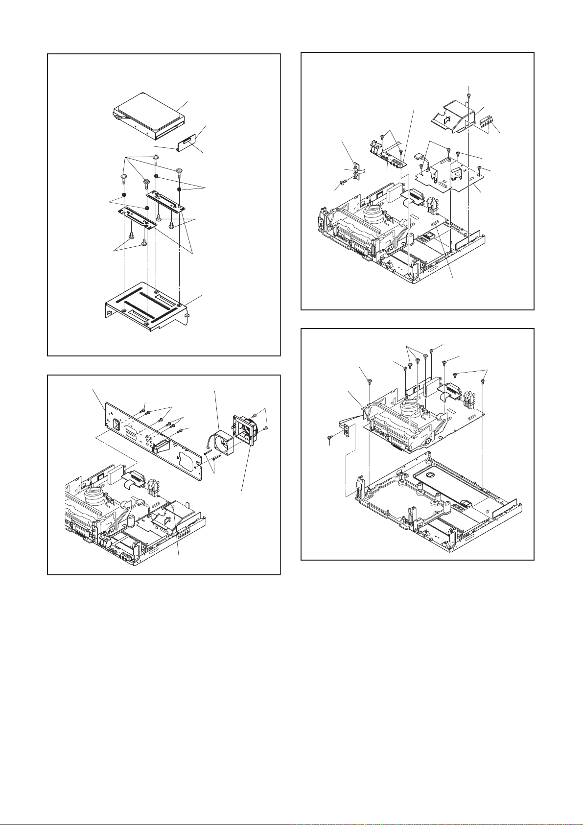
HDD Rubber
(S-12)
CN3001
[7] HDD Unit
[9] ATA CBA
CN3002
HDD Rubber
(S-13)
[14] SW CBA
Desolder
(S-22)
[15] Front Jack
CBA
(S-23)
(S-20)
CN3011
(S-19)
FFC Guide
Chassis
Earth Plate
(S-21)
(S-20)
[13] Power
Supply CBA
(S-13)
[12] Rear Panel
(S-16)
[8] HDD Support
[6] HDD Bracket
Fig. D4
[11] Motor DC Fan
(S-17)
(S-18)
(S-16)
(S-15)
[10] Fan Holder
(S-14)
(S-24)
[16] VCR
Chassis
Unit
(S-26)
(S-24)
(S-25)
CN1503
Fig. D6
(S-25)
(S-24)
(S-25)
CN1002
Fig. D7
Fig. D5
1-7-3 E3NF0DC
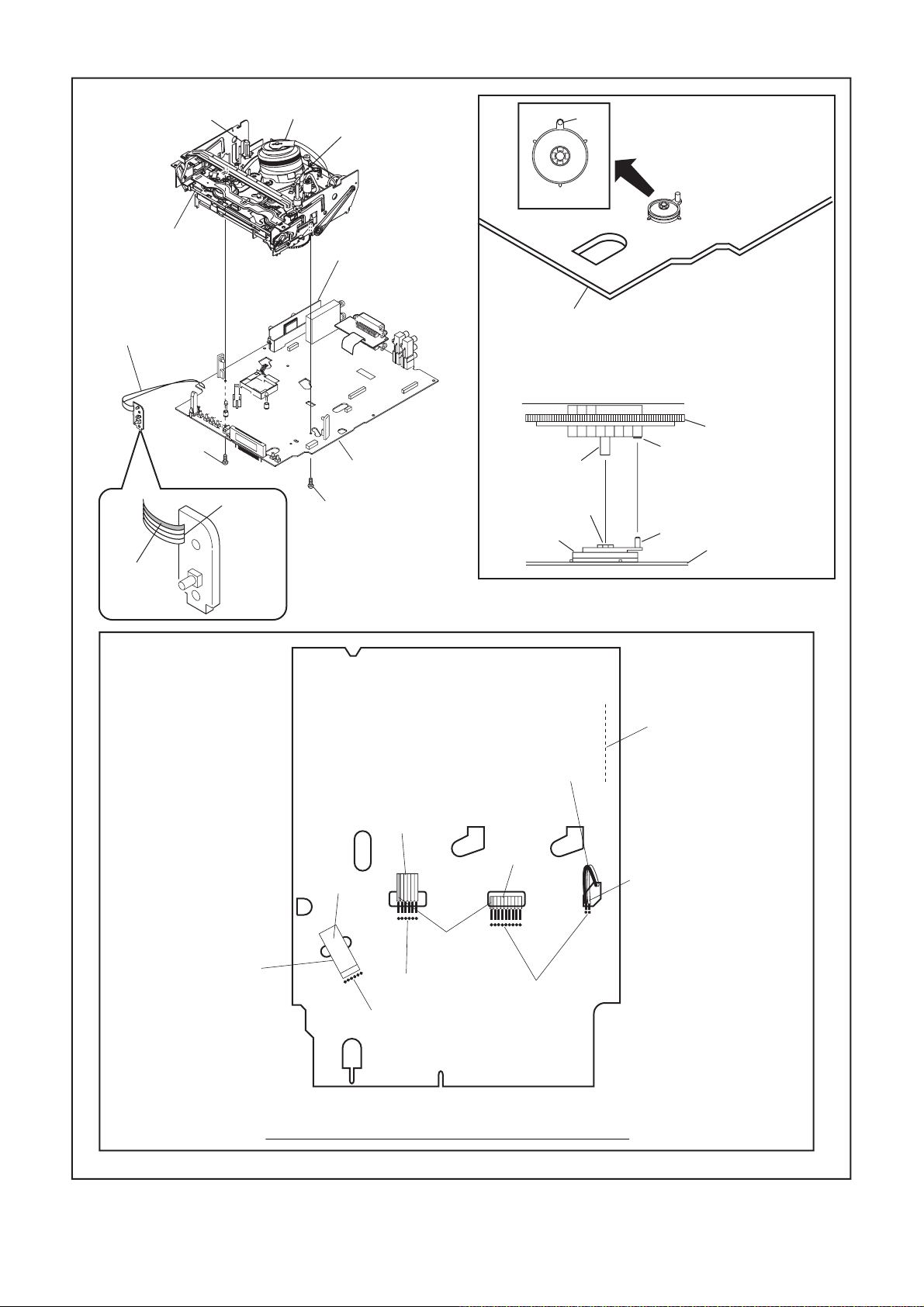
FE Head
[17] Deck
Assembly
Cylinder
Assembly
ACE Head
Assembly
[19] DTV Module
CBA Unit
Pin
Pin
SW507
LD-SW
[20] Power SW
CBA
(S-27)
Lead with
blue stripe
Desolder
[18] AV CBA
(S-28)
Printing side
From
ACE Head
Assembly
[18] AV CBA
[17] Deck Assembly
Shaft
Hole
LD-SW
From
FE Head
From
Cylinder
Assembly
Cam Gear
Hole
Pin
[18] AV CBA
Desolder
Lead with
white stripe
From
Capstan
Motor
Assembly
Lead with
blue stripe
Desolder
Desolder
Desolder
BOTTOM VIEW
Lead connections of Deck Assembly and AV CBA
1-7-4 E3NF0DC
Fig. D8
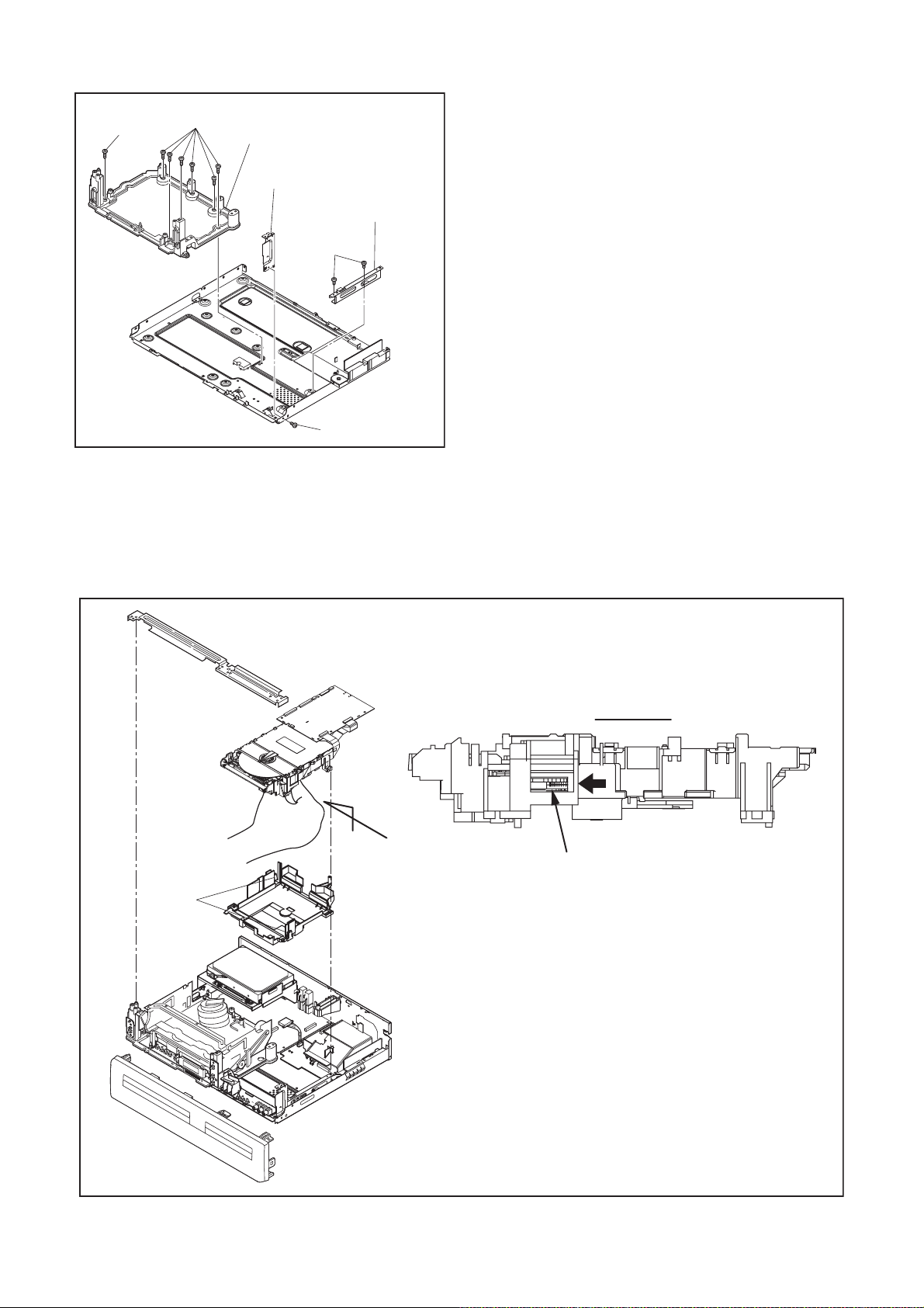
(S-29)
(S-29)
[21] Deck Pedestal
[22] Front Bracket R
[23] Bracket R
(S-31)
(S-30)
Fig. D9
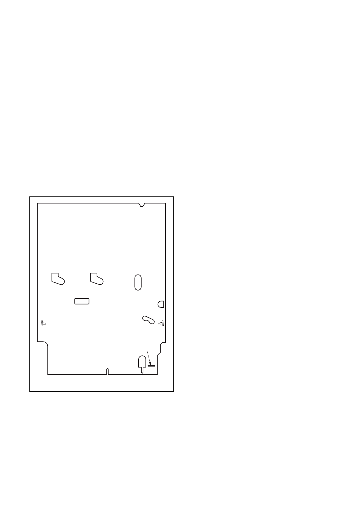
3. How to Eject Manually
Note: When rotating the gear, be careful not to damage the gear.
1. Remove the Top Cover, Front Assembly, Front Bracket, DVD Mechanism & DVD/HDD Main CBA Assembly.
2. Remove the Dust Cover.
3. Rotate the gear in the direction of the arrow manually as shown below.
View for A
A
Rotate this gear in
Hook
the direction of the arrow
1-7-5 E3NF0DC
ELECTRICAL ADJUSTMENT INSTRUCTIONS
g. (+)
NOTE:
1.Electrical adjustments are required after replacing
circuit components and certain mechanical parts.
It is important to do these adjustments only after
all repairs and replacements have been completed. Also, do not attempt these adjustments
unless the proper equipment is available.
2.To perform these alignment / confirmation procedures, make sure that the tracking control is set in
the center position: Press either [PROG.
[PROG.
[PLAY] (VCR) button on the front panel.
o] button on the front panel first, then the
p] or
CH1
CH2
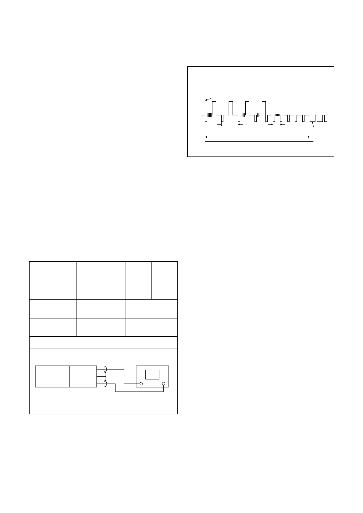
Figure 1
EXT. Syncronize Trigger Point
1.0H
6.5H±1H (416µs±64µs)
0.5H
V-Sync
Test Equipment Required
1.Oscilloscope: Dual-trace with 10:1 probe,
V-Range: 0.001~50V/Div.,
F-Range: DC~AC-20MHz
2.Alignment Tape (FL6A)
Head Switching Position Adjustment
Purpose:
To determine the Head Switching position during
playback.
Symptom of Misadjustment:
May cause Head Switching noise or vertical jitter
in the picture.
Test point Adj.Point Mode Input
J184(AV1-V-OUT1)
TP504(RF-SW)
GND
Tape
VR501
(Switching Point)
(AV CBA)
Measurement
Equipment
PLAY
(SP)
-----
Spec.
Switching Pulse
Reference Notes:
Playback the Alignment tape and adjust VR501 so that
the V-sync front edge of the CH1 video output waveform is at the 6.5H±1H (416µs±64µs) delayed position
from the rising edge of the CH2 head switching pulse
waveform.
FL6A Oscilloscope
Connections of Measurement Equipment
J184
AV CBA
GND
TP504
6.5H±1H
(416µs±64µs)
Oscilloscope
CH1 CH2
Tri
1-8-1 E3NF0EA
HOW TO SELF-CHECK AND HDD FORMAT
1. Turn on the HDD & DVD/VCR.
2. To put the HDD & DVD/VCR into the HDD mode, press [HDD] on the remote control unit.
3. To put the HDD & DVD/VCR into the self-check mode, after pressing [VARIABLE SKIP] button, press the [0],
[7], and [9] buttons on the remote control in that order within three seconds.
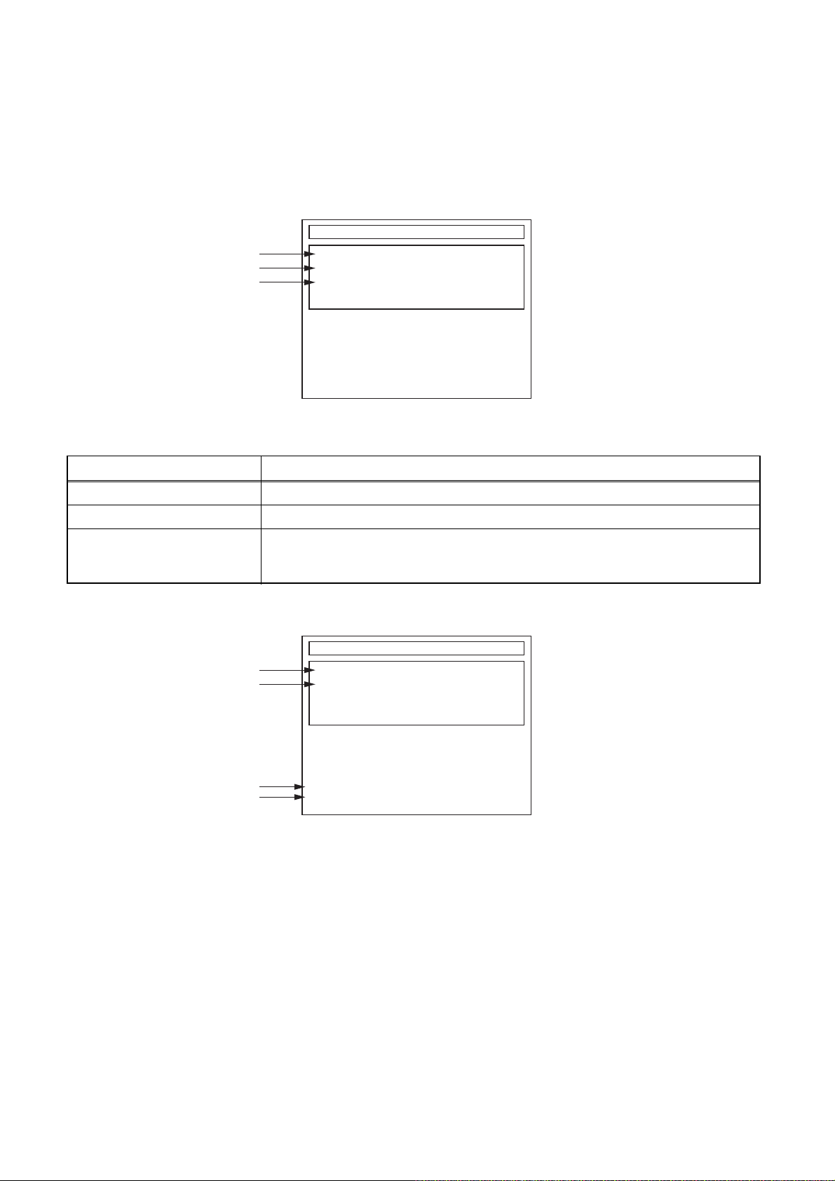
Fig. a appears on the screen and all LEDs light.
SELF CHECK
*1
*2
*3
DVD CONNECT STATUS :
HDD CONNECT STATUS :
HDD POWER ON HOURS :
HDD FORMAT START :
POWER OFF :
ENTER
POWER
Fig. a: Self-Check Mode Screen
Table 1: Description of Fig. a
INDICATION DESCRIPTION
DVD CONNECT STATUS (*1) Connecting Condition of DVD(F/E)
HDD CONNECT STATUS (*2) Connecting Condition of HDD
Value of HDD power on hours obtained from S.M.A.R.T. command. (If not obtainable,
HDD POWER ON HOURS (*3)
value of HDD power on hours is “0”.)
Value in parentheses is the factory setting value. (If no setting, the value is “0”.)
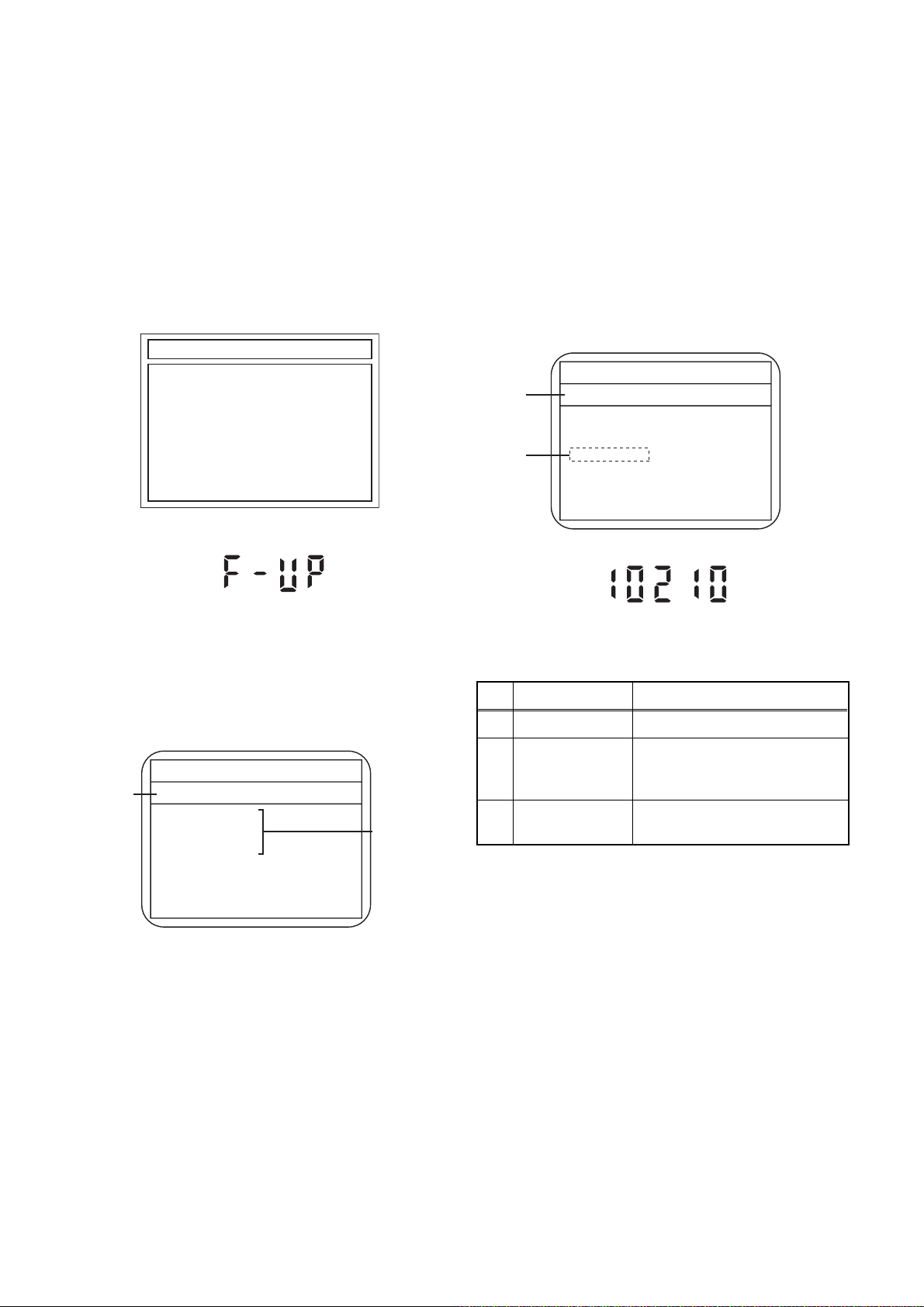
4. Upon the self-check completion, Fig. b appears on the screen.
SELF CHECK
*4
*5
DVD CONNECT STATUS : OK
HDD CONNECT STATUS : OK
HDD POWER ON HOURS : 70
*6
*7
HDD FORMAT START :
POWER OFF :
ENTER
POWER
Fig. b: Screen of Finishing Self-Check Mode
1-9-1 E3NF0INTH

Table 2: Indication of DVD self-check (*4)
INDICATION DESCRIPTION
OK Connection of DVD is normal.
NOT FOUND DVD drive cannot be found.
CABLE ERROR
FFC cable (connecting to CN652) between the DVD drive and the DVD/HDD Main CBA is
not connected correctly.
Table 3: Indication of HDD self-check (*5)
INDICATION DESCRIPTION
OK Connection of HDD is normal.
NOT FOUND HDD drive cannot be found.
CABLE ERROR FFC cable between the ATA CBA and the HDD drive is not connected correctly.
Table 4: Available button in self-check mode
BUTTON DESCRIPTION
ENTER/OK (*6) Format (only when the self-check mode is complete)
STANDBY-ON (*7) Turn the power off
OTHER Not available
5. When the self-check mode is complete, press [STANDBY-ON] button to turn the power off.
When formatting the HDD & DVD/VCR, press [ENTER/OK] button. After two seconds, the power is turned off
automatically.
NOTE: By formatting, “HDD Contents” is formatted.
1-9-2 E3NF0INTH

HOW TO INITIALIZE THE HDD & DVD/VCR
To put the program back at the factory-default,
initialize the HDD & DVD/VCR as the following
procedure.
< HDD/DVD Section >
1. Turn on the HDD & DVD/VCR.
2. To put the HDD & DVD/VCR into the HDD mode,
press [HDD] on the remote control unit.
3. To put the HDD & DVD/VCR into the Version
display mode, press [VARIABLE SKIP], [1], [2],
and [3] buttons on the remote control unit in that
order within three seconds.
Fig. a appears on the screen.
*1: "
*2: Firmware Version differs depending on the
models, and this indication is one example.
" differs depending on the models.
*******
F/W VERSION DISP
MODEL NAME :
DVB-T VERSION :
FE VERSION :
BE VERSION :
TT VERSION :
LD ADJUSTMENT :
DISC ADJUSTMENT :
DEFAULT SETTING : ENTER
EXIT : RETURN
*******
*.**
***_***_***
************
*********
OK
OK
Fig. a Version Display Mode Screen
4. Press [ENTER/OK] button, then the HDD & DVD/
VCR starts initializing. When the initializing is
completed, the HDD & DVD/VCR exits the Version
display mode and turns off the power
automatically.
* To move into the Normal mode from the
Version display mode, press [RETURN/BACK]
button on the remote control unit instead of
[ENTER/OK] button.
* When [STANDBY-ON] button is pressed
before [ENTER/OK] button is pressed, the
HDD & DVD/VCR exits the Version display
mode, then the power turns off.
NOTE: By initializing, “Current Clock”, “Setup
Changing Item”, “Channel Setup” and “Timer
Program” are initialized.
1-10-1 E3NF0INT
FIRMWARE RENEWAL MODE
1. Turn the power on and remove the disc in the tray.
2. To put the HDD & DVD into the HDD mode, press
[HDD] on the remote control unit.
3. To put the HDD & DVD into version up mode,
press [VARIABLE SKIP], [6], [5], and [4] buttons
on the remote control unit in that order within three
seconds. The tray will open automatically.
Fig. a appears on the screen and Fig. b appears
on the VFD.
*FIRMWARE version will differ depending on the
model. Fig. a is an example.
Firm Update Mode ver.************
Please insert a disc.
Fig. a: Update Mode TV Screen
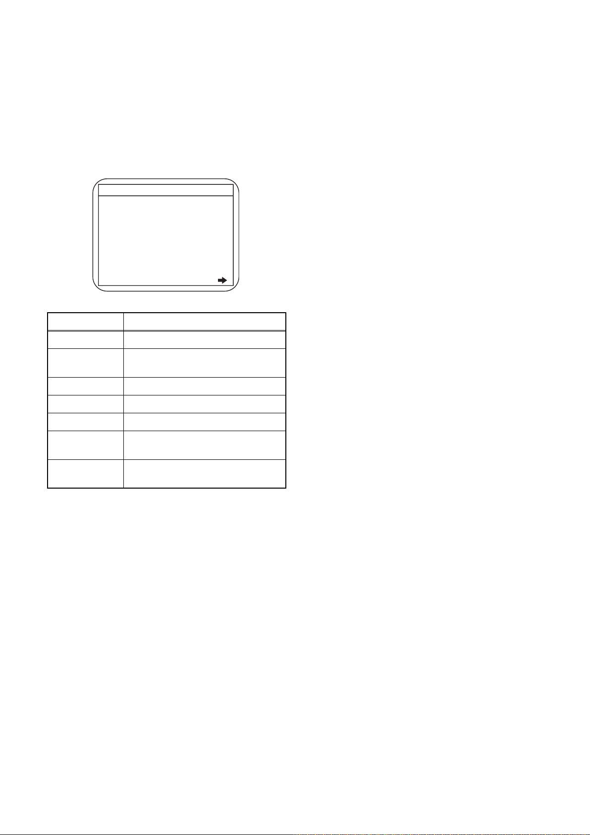
5. Select the firmware version pressing arrow
buttons, then press [ENTER/OK].
Fig. d appears on the screen and Fig. e appears
on the VFD. The DVD recorder starts updating.
About VFD indication of Fig. e:
1) When Fig. d is displayed on the screen, “F-UP”
is displayed on the VFD.
2) When “Firmware Updating... XX% Complete.”
is displayed on the screen, “10210” is displayed
on the VFD.
* Firmware Version differs depending on the
models, and this indication is one example.
Selected
F/W Version
is displayed.
(*1)
Firm Update Mode
************
File Loading...
Fig. d Programming Mode Screen
ver. ***
********
Fig. b: VFD Display in Update Mode
4. Load the disc for version up.
Fig. c appears on the screen. The file on the top is
highlighted as the default.
When there is only one file to exist, Step 5 will
start automatically.
* Firmware Version differs depending on the
models, and this indication is one example.
Firm Update Mode ver. ************
Disc name
is displayed.
VOL_************
1 ************
2 ************
3 ************
4 ************
Files included
in the disc are
displayed.
1 / 1
Fig. c: Update Disc TV Screen
Fig. e VFD in Programming Mode (Example)
The appearance shown in (*1) of Fig. d is
described as follows.
No. Appearance State
1 File Loading... Sending files into the memory
Firmware
2
Updating...
Writing new version data
XX% Complete.
Firmware
--Update Failure
Failed in updating
6. After updating is finished, the tray opens
automatically.
At this time, no button is available.
7. Pull out the AC code once, then insert it again.
1-11-1 E3NF0FW
How to Verify the Firmware Version
1. Turn the power on and remove the disc in the tray.
2. To put the HDD & DVD into HDD mode, press
[HDD] on the remote control unit.
3. To put the HDD & DVD into version display mode,
press [VARIABLE SKIP], [1], [2], and [3] buttons
on the remote control unit in that order within three
seconds. Fig. i appears on the screen.
*1: "
*2: Firmware Version differs depending on the
models, and this indication is one example.
Display Contents
" differs depending on the models.
*******
F/W VERSION DISP
MODEL NAME :
DVB-T VERSION :
FE VERSION :
BE VERSION :
TT VERSION :
LD ADJUSTMENT :
DISC ADJUSTMENT :
DEFAULT SETTING : ENTER
EXIT : RETURN
*******
*.**
***_***_***
************
*********
OK
OK
Fig. i: Firmware version display
MODEL NAME Model Name
DVB-T
VERSION
DVB-T Module version
FE VERSION Firmware F/E version
BE VERSION Firmware B/E version
TT VERSION Firmware T/T version
LD
ADJUSTMENT
DISC
ADJUSTMENT
LD adjustment progress (done: OK/
not done: --)
Factory adjustment progress (done:
OK/not done: --)
4. Press [RETURN/BACK] or [STANDBY-ON] button
to turn off.
Note: Be sure to verify the firmware version.
1-11-2 E3NF0FW
FUNCTION INDICATOR SYMBOLS
< VCR Section >
Note:
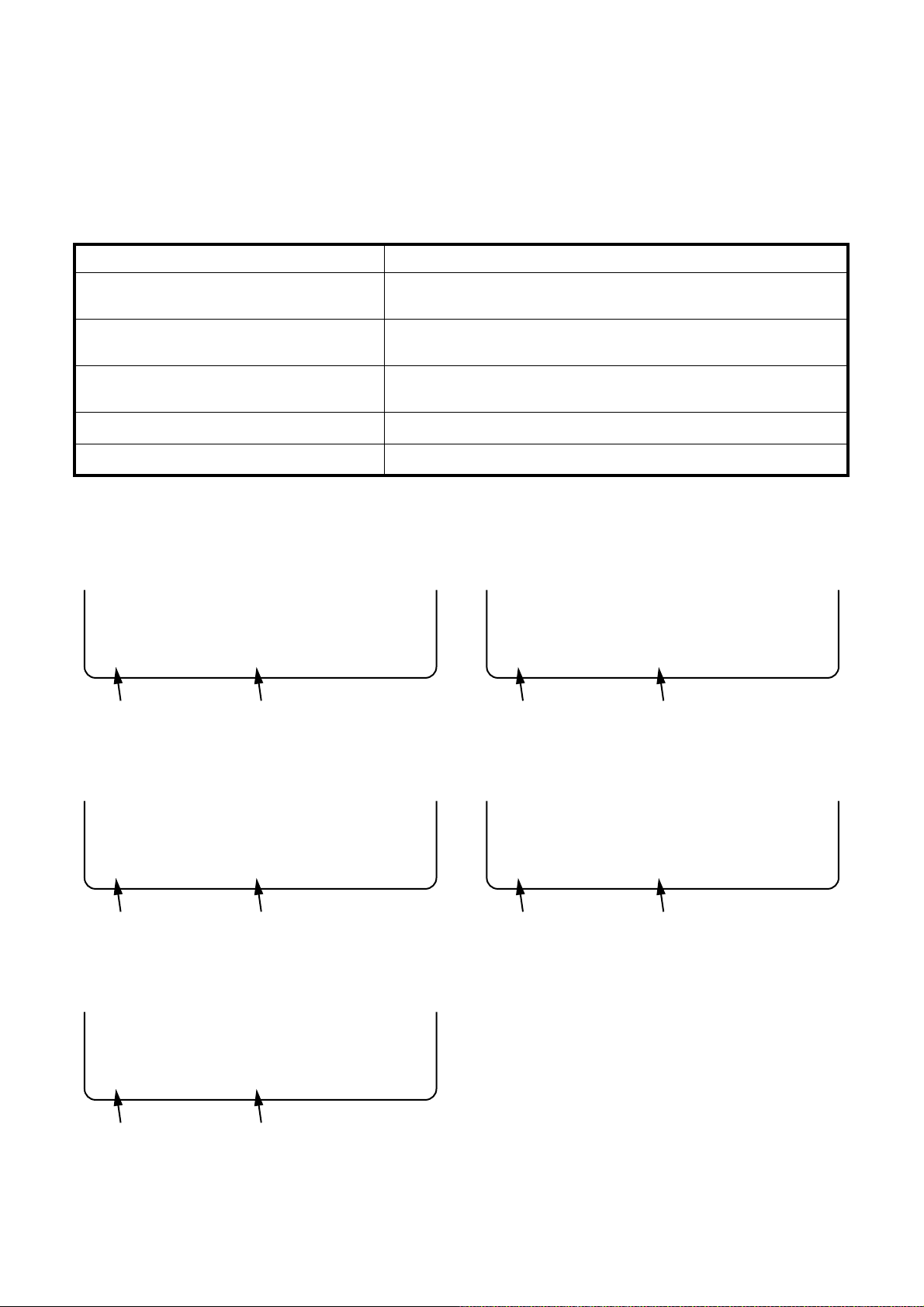
If a mechanical malfunction occurs, the power is turned off. When the power comes on again after that by
pressing [STANDBY-ON] button, an error message is displayed on the TV screen for 5 seconds.
MODE INDICATOR ACTIVE
When reel or capstan mechanism is not
functioning correctly
When tape loading mechanism is not functioning correctly
When cassette loading mechanism is not
functioning correctly
When the drum is not working properly
P-ON Power safety detection
“A R” is displayed on a TV screen. (Refer to Fig. 1.)
“A T” is displayed on a TV screen. (Refer to Fig. 2.)
“A C” is displayed on a TV screen. (Refer to Fig. 3.)
“A D” is displayed on a TV screen. (Refer to Fig. 4.)
“A P” is displayed on a TV screen. (Refer to Fig. 5.)
TV screen
When reel or capstan mechanism is not functioning
correctly
A
R
SP 0 : 00 : 00
Recording mode
Elapsed time
Fig. 1
When the drum is not working properly
A
D
SP 0 : 00 : 00
Recording mode
Elapsed time
Fig. 4
When tape loading mechanism is not functioning correctly
A
T
SP 0 : 00 : 00
Recording mode
When cassette loading mechanism is not functioning
correctly
A
C
Elapsed time
Fig. 2
SP 0 : 00 : 00
Recording mode
Elapsed time
Fig. 3
P-ON Power safety detection
A
P
SP 0 : 00 : 00
Recording mode
Elapsed time
Fig. 5
1-12-1 E3NF0FIS
< DVD Section >
Note: If an error occurs, a message with the error number appears on the screen.
Recording Error
Message Solution
Can not record on this disc.
This program is not allowed to
be recorded.
This program is not recordable
in Video mode.
This program is not allowed to
be recorded on this disc.
You cannot record on this disc as
Power Calibration Area is full.
E35
Insert the recordable disc, and
ensure the disc status satisfies
the recording requirements.
You cannot record copyprohibited programs.
You cannot record copyprohibited programs.
You cannot record copyprohibited programs.
Error message
Error No.
Error
No.
1 An error occurs during data reading.
There is no reply for 15 seconds in Test
2
Unit Ready.
Cannot write the data after trying three
3
times.
4 An error occurs with OPC.
5 During recovery in a record.
An error occurs even if recovery has been
6
tried three times.
7 An error occurs in a format.
8 It cannot start an encode.
NV_PCK/RDI_PCK is not in encoded
9
data.
Encode Pause condition continued for 10
10
minutes.
Encode Pause condition continued in
11
normal REC condition for 10 minutes.
Difference in the address and can not get
12
Stream ID of RDI/VIDEO.
13 It is a reply that “ATAPI is not readable.”
Cannot write the data after recovering
14
SMALL VMGI.
Cannot write the data after DVD-R
15
Reverse Track.
16 An error occurs in Finalize Close.
17 An error occurs in Rec Stop Close.
18 An error occurs in PCA Full (DVD_R).
19 Safety Stop occurs during editing.
20 High Speed Disc.
21 The disc is not formatted.
22 Disc Error has occurred.
23 The -R Disc of VR Mode.
24 The disc except DVD-R/-RW.
25 During the Macrovision picture input.
26 During the CGMS picture input.
During the CGMS picture input. (Video
27
Format Disc)
During the CGMS picture input. (VR
28
Format Disc that is not compatible with
CPRM.)
Error Description
1-12-2 E3NF0FIS
Message Solution
This disc is protected and not
recordable.
Disc is full.
(No area for new recording)
You cannot record more than
99 titles on one disc.
(The maximum is 99.)
You cannot record more than
999 chapters on one disc.
(The maximum is 999.)
You cannot record on this disc
as Control Information is full.
You cannot record on the disc
as Power Calibration Area is
full.
This disc is already finalized.
Can not record on this disc. Repeat the same operation.
This program is not recordable
in +VR mode.
HDD is full.
This Program is not allowed to
be recorded.
Release the disc protection
setting in the Disc Setting
menu.
Insert the recordable disc with
enough recording space.
Delete unnecessary titles.
Delete unnecessary chapters. 33
Insert a new disc. 34
Insert a new disc. 35 PCA is Full. (in REC start)
Release the finalizing for this
disc.
You cannot record copyprohibited programs.
Delete unnecessary titles. 49
Delete unnecessary titles. 50 HDD is full during recording.
Receive PAL/SECAM signal. 51
Error
No.
29 Disc Protected Disc.
30 No available recording space.
The 99 title limit has been reached.
31
(Video Format Disc)
The 99 title limit has been reached. (VR
32
Format Disc)
The 999 chapter limit has been reached.
(VR Format Disc)
No available recording space for Control
Information.
36 It is finalized. (Video Format Disc)
37 Access to Memory Area range outside.
38 Sector Address is wrong.
39 BUP writing error of chapter editing.
During the CGMS picture input (+VR
45
Format Disc).
The REC key was pushed when HDD
was full.
When you receive signal other than PAL/
SECAM.
Error Description
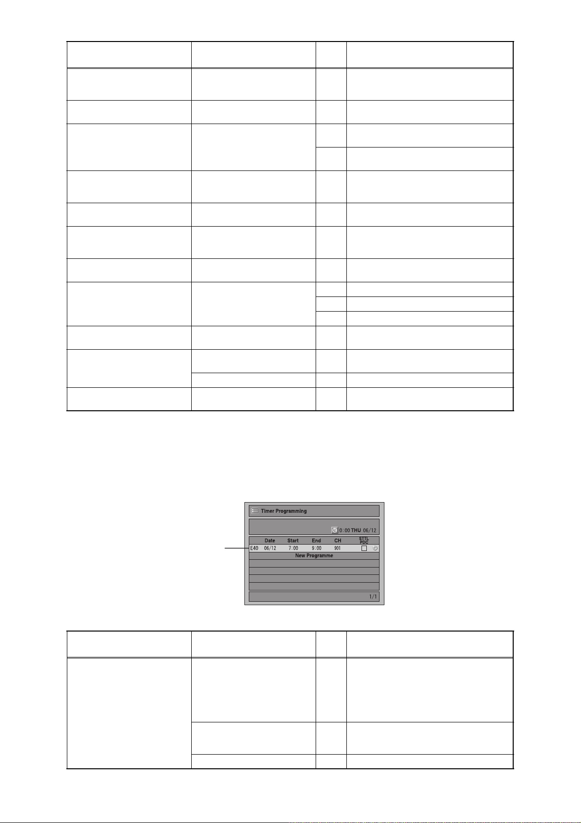
If an error occurs during the timer recording, one of the following error numbers (40 to 42) or the above
error messages (error number: 1 to 39, 45 and 49 to 51) is displayed on the recording menu after timer
recording.
(Once the screen of the program line is exited, the program line for the error will be cleared.)
(No Error Message is displayed for the error No. 40 ~ 42.)
Error number
A program with the error number is grayed out on the timer programming list.
Message Solution
Error message is not
displayed.
- Set the timer programming
correctly.
- Set the timer programming
before the start time.
- Insert a recordable videotape
with a record tab.
Turn the power on and set the
clock correctly then set timer
programming again.
Insert the recordable disc. 42 No disc when recording
Error
No.
- Some portion has not been recorded
because of program overlapping.
40
- Recording did not start at the start time.
- No Videotape is inserted.
Videotape ran out during recording.
41 Power failed
Error Description
1-12-3 E3NF0FIS
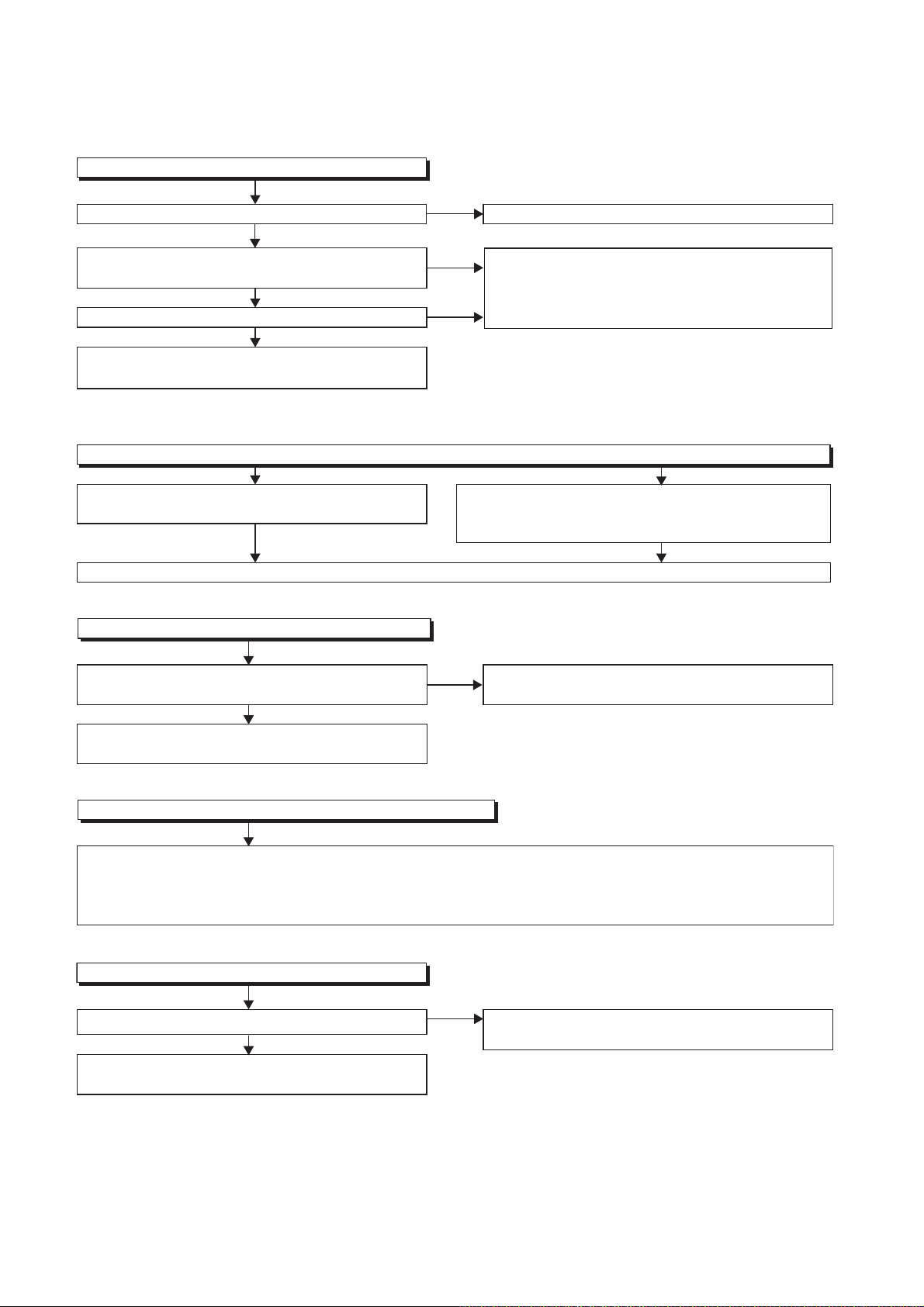
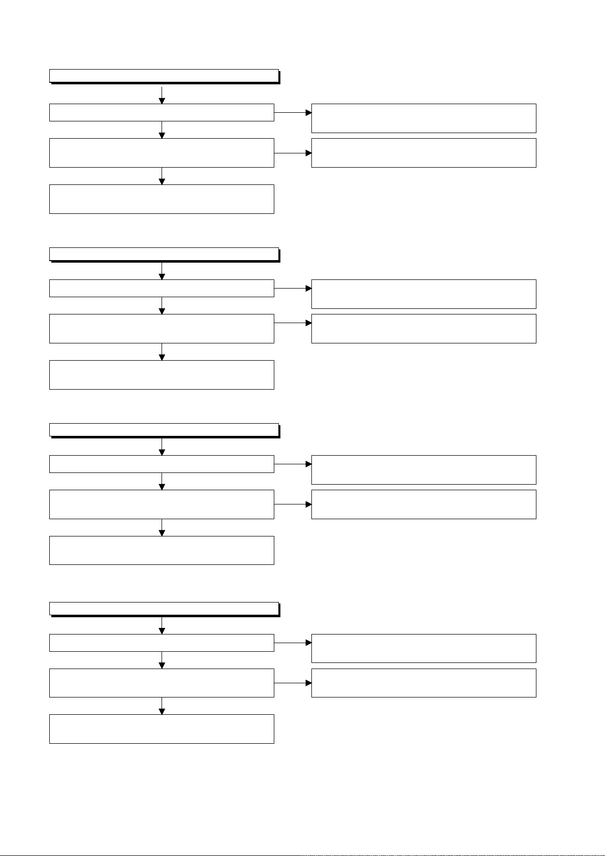
1 Power Supply Section
FLOW CHART NO.1
The power cannot be turned on.
TROUBLESHOOTING
Is the fuse normal?
Ye s
Is normal state restored when once unplugged power
cord is plugged again after several seconds.
Ye s
Is the AL+5V line voltage normal?
Ye s
Check each rectifying circuit of secondary circuit
and service it if defective.
FLOW CHART NO.2
The fuse blows out.
Check the presence that the primary component
is leaking or shorted and service it if defective.
After servicing, replace the fuse.
FLOW CHART NO.3
When the output voltage fluctuates.
No
No
No
See FLOW CHART No.2 <The fuse blows out.>
Check for lead or short-circuiting of primary
circuit component and service it if defective.
(Q1001, Q1003, T1001, D1001, D1002, D1003,
D1004, D1011, R1003)
Check the presence that the rectifying diode or circuit
is shorted in each rectifying circuit of secondary side
and service it if defective.
Does the secondary side photo coupler circuit operate
normally?
Ye s
Check the circuit and service it if defective.
(IC1001, D1025, D1022, D1023)
FLOW CHART NO.4
When buzz sound can be heard in the vicinity of power circuit.
Check if there is short circuit on the rectifying diode and the circuit in each rectifying circuit of secondary side,
and service it if defective. (D013, D014, D016, D018, D019, D1031, D1032, D1033, D1034, D1035,
D1101, D1103, IC1103, IC1104, IC1105, IC1800, Q1100, Q1102, Q1105, Q1106, Q1108, Q1112, Q1114, Q1502,
Q1508, Q1511, Q1513, Q1516, Q1517, Q1520, Q1521, Q1527)
FLOW CHART NO.5
-FL is not outputted.
Is the supply voltage of -24V fed to the anode of D018?
Ye s
Check for load circuit short-circuiting or leak, and
service it if defective.
No
No
Check the circuit and service it if defective.
(IC1001, IC1101, D1102)
Check D018 and their periphery, and service it if
defective.
1-13-1 E3NF0TR
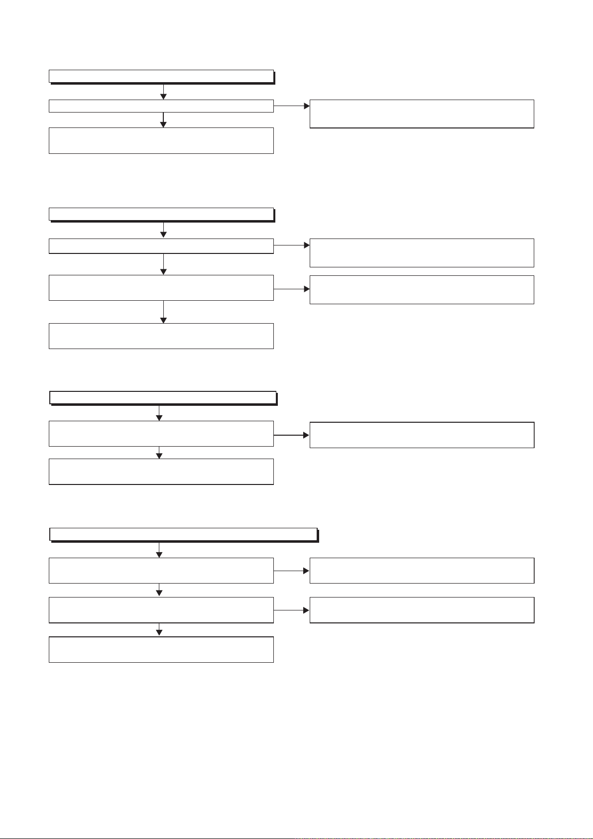
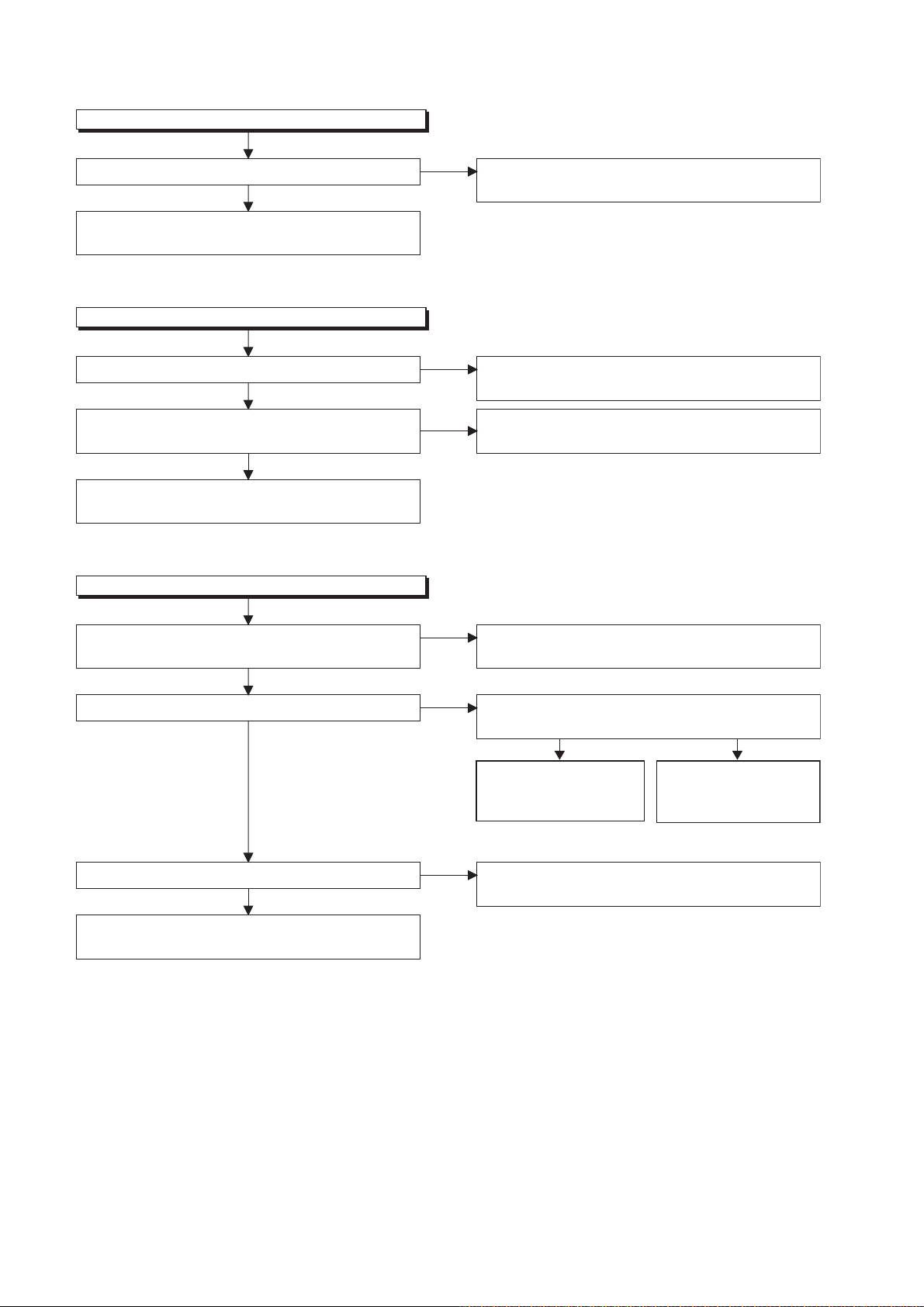
FLOW CHART NO.6
AL+15V is not outputted.
Is the supply voltage 44V fed to the cathode of D013?
Ye s
Check for load circuit short-circuiting or leak, and
service it if defective
FLOW CHART NO.7
TU+30V is not outputted.
Is 44V voltage supplied to emitter of Q1511?
Ye s
Is the "H" pulse (approximately 5V) inputted to
the base of Q1512?
Ye s
Check Q1511, Q1512 and their periphery, and
service it if defective.
FLOW CHART NO.8
No
No
No
Check D013 and their periphery, and service it if
defective.
Refer to "FLOW CHART NO.6"<AL+15V is not
outputted>.
Check the P-ON-H siganal line, and service it if
defective.
AL+12V is not outputted.
Is the supply voltage 12V fed to the cathode of D014?
Ye s
Check for load circuit short-circuiting or leak, and
service it if defective.
FLOW CHART NO.9
P-ON+9V is not outputted.
Is 12V voltage supplied to collector of Q1513?
Ye s
Is the "H" pulse (approximately 10V) inputted to
the base of Q1513?
Ye s
Check Q1513 and their periphery, and
service it if defective.
No
No
No
Check D014 and their periphery, and service it if
defective.
Refer to "FLOW CHART NO.8"<AL+12V is not
outputted>.
Refer to "FLOW CHART NO.7"<TU+30V is not
outputted>.
1-13-2 E3NF0TR
FLOW CHART NO.10
P-ON+5V(DECK) is not outputted.
Is 12V voltage supplied to collector of Q1516?
Ye s
Is the "H" pulse (approximately 6V) inputted to
the base of Q1516?
Ye s
Check Q1516 and their periphery, and service it if
defective.
FLOW CHART NO.11
AL+5V is not outputted.
Is the supply voltage 5V fed to the cathode of D016?
Ye s
Is the "H" pulse (approximately 5V) inputted to
the base of Q1502?
Ye s
Check Q1502 and their periphery, and service it if
defective.
No
No
No
No
Refer to "FLOW CHART NO.8"<AL+12V is not
outputted>.
Refer to "FLOW CHART NO.9"<P-ON+9V is not
outputted>.
Check D016 and their periphery, andservice it if
defective.
Refer to "FLOW CHART NO.8"<AL+12V is not
outputted>.
FLOW CHART NO.12
P-ON+5V is not outputted.
Is 5V voltage supplied to collector of Q1517?
Ye s
Is the "H" pulse (approximately 6V) inputted to
the base of Q1517?
Ye s
Check Q1517 and their periphery, and
service it if defective.
FLOW CHART NO.13
ECO+5V is not outputted.
Is 5V voltage supplied to collector of Q1520?
Ye s
Is the "H" pulse (approximately 6V) inputted to
the base of Q1520?
Ye s
No
No
No
No
Refer to "FLOW CHART NO.11"<AL+5V is not
outputted>.
Refer to "FLOW CHART NO.9"<P-ON+9V is not
outputted>.
Refer to "FLOW CHART NO.11"<AL+5V is not
outputted>.
Refer to "FLOW CHART NO.14"<ECO+9V is not
outputted>.
Check Q1520 and their periphery, and
service it if defective.
1-13-3 E3NF0TR
FLOW CHART NO.14
ECO+9V is not outputted.
Is 10V voltage supplied to collector of Q1521?
Ye s
Check Q1521 and their periphery, and service
it if defective.
FLOW CHART NO.15
P-ON+5V(2) is not outputted.
Is the supply voltage 5V fed to the cathode of D016?
Ye s
Is the "H" pulse (approximately 6V) inputted to
the base of Q1106?
Ye s
Check Q1106 and their periphery, and
service it if defective.
FLOW CHART NO.16
P-ON+10V is not outputted.
No
No
No
Refer to "FLOW CHART NO.8"<AL+12V is not
outputted>.
Check D016 and their periphery, and service it if
defective.
Refer to "FLOW CHART NO.16"<P-ON+10V is not
outputted>.
Is the supply voltage 14V fed to the cathode
of D1031?
Ye s
Is 12V voltage supplied to collector of Q1105?
Ye s
Is 10V voltage outputed to Pin(12) of CL1001? Cheak Q1105 and their periphery, and service
Ye s
Check for load circuit short-circuiting or leak, and
service it if defective.
No
No
No
Check D1031 and their periphery, and service it if
defective.
Is the "H" pulse (approximately 0.7V) inputted to
the base of Q1104?
Ye s
Check Q1101, Q1104
and their periphety, and
service it if defective.
it if defective.
Check the POW-SW
signal line, and
it if defective.
No
service
1-13-4 E3NF0TR
 Loading...