

Page 1
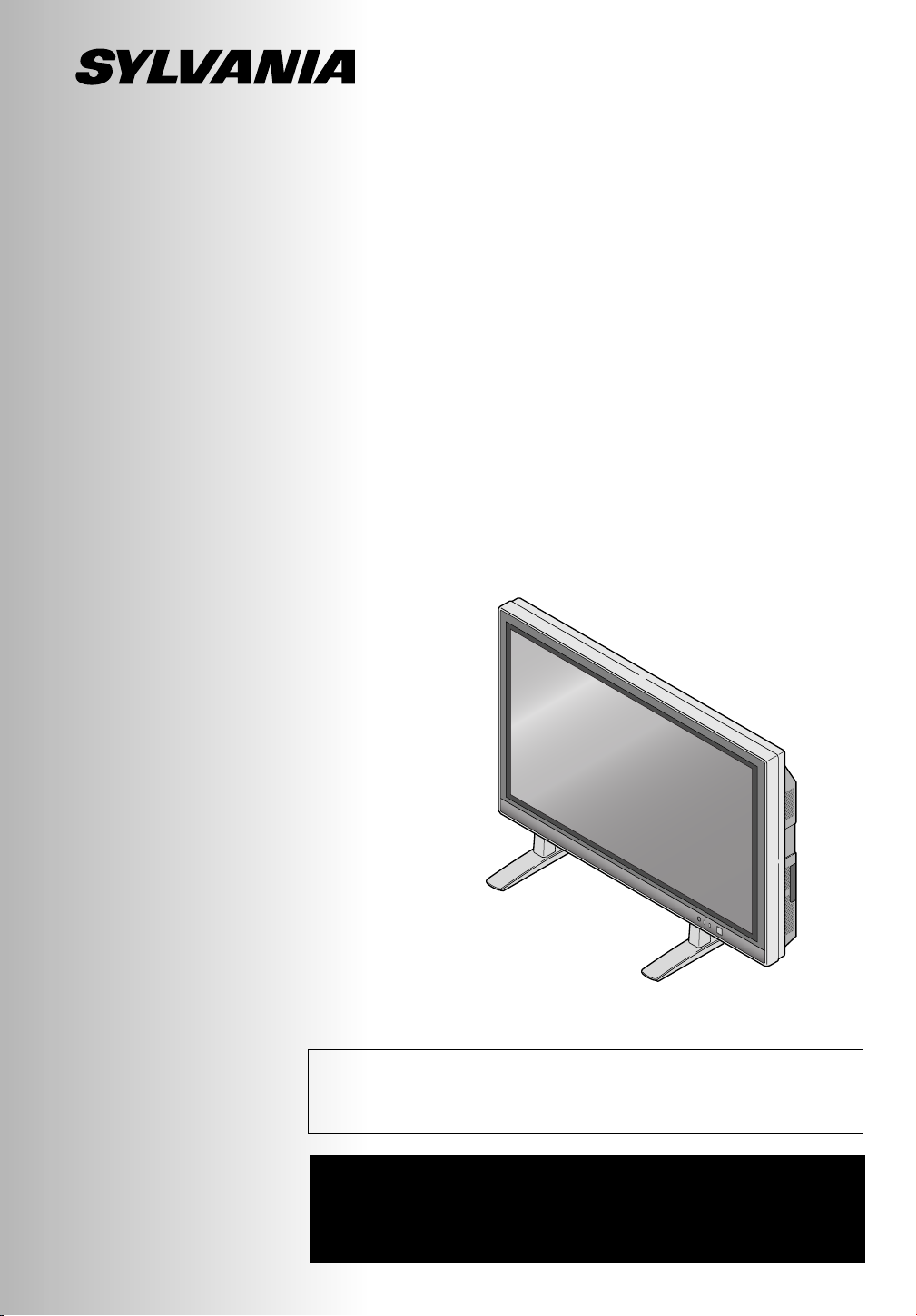
PLASMA DISPLAY
Owner’s Manual
SRPD442
Before you can view a picture on the plasma display, you
must first connect the unit to an external video source. See
page 21 of the owner’s manual.
IF YOU NEED ADDITIONAL ASSISTANCE FOR SET-UP
OR OPERATING AFTER READING OWNER’S MANUAL,
PLEASE CALL TOLL FREE
1-800-968-3429.
Page 2
WARNING:
TO REDUCE THE RISK OF FIRE OR ELECTRIC SHOCK, DO NOT EXPOSE THIS APPLIANCE TO RAIN OR MOISTURE.
CAUTION
RISK OF ELECTRIC SHOCK
DO NOT OPEN
THIS SYMBOL INDICATES THAT DANGEROUS VOLTAGE CONSTITUTING A
RISK OF ELECTRIC SHOCK IS PRESENT WITHIN THIS UNIT.
CAUTION: TO REDUCE THE RISK OF ELECTRIC
SHOCK, DO NOT REMOVE COVER (OR BACK) NO
USER SERVICEABLE PARTS INSIDE. REFER SERVICING TO QUALIFIED SERVICE PERSONNEL.
THIS SYMBOL INDICATES THAT THERE
ARE IMPORTANT OPERATING AND
MAINTENANCE INSTRUCTIONS IN THE
LITERATURE ACCOMPANYING THE
APPLIANCE.
The important note is located on the rear of the cabinet.
IMPORTANT SAFETY INSTRUCTIONS
1. Read these instructions.
2. Keep these instructions.
3. Heed all warnings.
4. Follow all instructions.
5. Do not use this apparatus near water.
6. Clean only with dry cloth.
7. Do not block any ventilation openings. Install in accordance with the manufacturer's instructions.
8. Do not install near any heat sources such as radiators,
heat registers, stoves, or other apparatus (including
amplifiers) that produce heat.
9. Do not defeat the safety purpose of the polarized or
grounding-type plug. A polarized plug has two blades
with one wider than the other. A grounding-type plug
has two blades and a third grounding prong. The wide
blade or the third prong are provided for your safety. If
the provided plug does not fit into your outlet, consult an
electrician for replacement of the obsolete outlet.
10. Protect the power cord from being walked on or pinched
particularly at plugs, convenience receptacles, and the
point where they exit from the apparatus.
11. Only use attachments/accessories specified by the
manufacturer.
12. Use only with the cart, stand, tripod,
bracket, or table specified by the
manufacturer, or sold with the apparatus. When a cart is used, use caution when moving the cart/apparatus
combination to avoid injury from tipover.
13. Unplug this apparatus during lightning storms or when
unused for long periods of time.
14. Refer all servicing to qualified service personnel.
Servicing is required when the apparatus has been
damaged in any way, such as power-supply cord or plug
is damaged, liquid has been spilled or objects have fallen into the apparatus, the apparatus has been exposed
to rain or moisture, does not operate normally, or has
been dropped.
15. Apparatus shall not be exposed to dripping or splashing
and no objects filled with liquids, such as vases, shall be
placed on the apparatus.
To reduce the risk of fire or electric shock, do not
expose this appliance to rain or moisture.
S3125A
2
Page 3
RADIO-TV INTERFERENCE
This equipment has been tested and found to comply with the limits for a Class B digital device, pursuant
to Part 15 of the FCC Rules. These limits are designed to provide reasonable protection against harmful
interference in a residential installation. This equipment generates, uses, and can radiate radio frequency
energy and, if not installed and used in accordance with the instructions, may cause harmful interference
to radio communications. However, there is no guarantee that interference will not occur in a particular
installation. If this equipment does cause harmful interference to radio or television reception, which can be
determined by turning the equipment off and on, the user is encouraged to try to correct the interference
by one or more of the following measures:
1) Reorient or relocate the receiving antenna.
2) Increase the separation between the equipment and receiver.
3) Connect the equipment into an outlet on a circuit different from that to which the receiver is connected.
4) Consult the dealer or an experienced radio/TV technician for help.
This Class B digital apparatus complies with Canadian ICES-003.
Cet appareil numérique de la classe B est conforme à la norme NMB-003 du Canada.
FCC WARNING-
equipment may cause harmful interference unless the modifications are expressly approved in the instruction manual. The user could lose the authority to operate this equipment if an unauthorized change or modification is made.
The serial number of this product may be found on the back of this unit. No others have the same serial
number as yours.You should record the number and other vital information here and retain this book as
a permanent record of your purchase to aid identification in case of theft.
Date of Purchase
Dealer
Dealer Address
This equipment may generate or use radio frequency energy. Changes or modifications to this
Dealer Phone No.
Model No.
Serial No.
IMPORTANT SAFETY INSTRUCTIONS
3
Page 4
IMPORTANT SAFETY INSTRUCTIONS
Thank you for purchasing this plasma display.
Please make sure to read this manual before using the plasma display, and pay particular
attention to the Safety Instructions enclosed within.
When you have finished reading this manual, store it in a safe place for easy access in the
future.
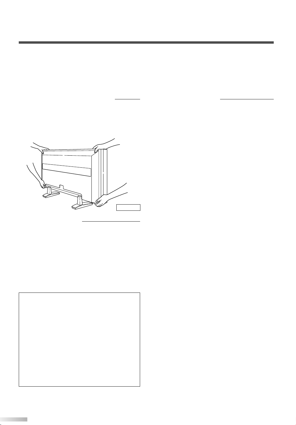
When moving the plasma display
Due to the weight of this plasma display, two people should be used when moving it. Both people
should make sure to grasp the top of the display
with one hand, and the base of the display with
the other hand, as in the following illustration.
Figure 1
Optional Accessories
To mount the plasma display on a wall, the following accessory is available:
VISIONMOUNT™ Flat Panel TV Wall Mount from
SANUS SYSTEMS, for large flat panel televisions
(32” to 60”). Refer to page 25 for mounting the
plasma display.
Regarding This Manual
• Product and company names appearing within
this manual are trademarks or registered trademarks of their respective owners.
• Although special care has been taken to ensure
that all information contained within this manual
is correct at time of writing, the information is
subject to change without notice.
• Make sure to read the manual carefully and follow all instructions contained within. We will not
be held responsible for any damages caused by
improper use or handling of this product.
• Reproducing this manual by any means, in
whole or in part, is prohibited.
NOTE
The wall mounts are not supplied with the plasma display.
#
CAUTION
• This PDP SRPD442 is for use only with the
Sanus Systems Model VMPL. Wall Mount.
Use with other wall mounts is capable of
resulting in instability, causing possible injury.
• When mounting the plasma display with the
Sanus Systems wall mount, make sure to
mount it on the wood studs inside the wall, as
failure to do so may result in instability, causing possible injury.
• Refer to the instruction manual included with
the wall mount for details when securing the
plasma display to the wall.
4
Page 5

ONTENTS
C
IMPORTANT SAFETY INSTRUCTIONS . . . . . . . . . . . . . . . . . . . . . . . . . . . . . . .2
SUPPLIED ACCESSORIES . . . . . . . . . . . . . . . . . . . . . . . . . . . . . . . . . . . . . . . .6
INSERTING THE REMOTE CONTROL BATTERIES . . . . . . . . . . . . . . . . . . . . . .7
REMOTE CONTROL RANGE . . . . . . . . . . . . . . . . . . . . . . . . . . . . . . . . . . . . . . .7
COMPONENT NAMES . . . . . . . . . . . . . . . . . . . . . . . . . . . . . . . . . . . . . . . . . . . .8
MAIN UNIT . . . . . . . . . . . . . . . . . . . . . . . . . . . . . . . . . . . . . . . . . . . . . . . . . . . . . . . . .8
REMOTE CONTROL . . . . . . . . . . . . . . . . . . . . . . . . . . . . . . . . . . . . . . . . . . . . . . . . . .9
OPERATING THE PLASMA DISPLAY . . . . . . . . . . . . . . . . . . . . . . . . . . . . . . .10
BASIC OPERATIONS . . . . . . . . . . . . . . . . . . . . . . . . . . . . . . . . . . . . . . . . . . . . . . . .10
SELECTING THE INPUT SIGNAL . . . . . . . . . . . . . . . . . . . . . . . . . . . . . . . . . . . . . . .11
CHANGING THE ASPECT RATIO (SCREEN MODE) . . . . . . . . . . . . . . . . . . . . . . . . .12
STILL . . . . . . . . . . . . . . . . . . . . . . . . . . . . . . . . . . . . . . . . . . . . . . . . . . . . . . . . . . . . .13
SLEEP . . . . . . . . . . . . . . . . . . . . . . . . . . . . . . . . . . . . . . . . . . . . . . . . . . . . . . . . . . . .13
NAVIGATING THE SET UP MENU . . . . . . . . . . . . . . . . . . . . . . . . . . . . . . . . . . . . . . .14
Layout of the Setup Menu . . . . . . . . . . . . . . . . . . . . . . . . . . . . . . . . . . . . . . . . . . .14
ENTERING THE MAIN MENU . . . . . . . . . . . . . . . . . . . . . . . . . . . . . . . . . . . . . . . . . .15
PICTURE SELECT . . . . . . . . . . . . . . . . . . . . . . . . . . . . . . . . . . . . . . . . . . . . . . . . . .15
Automatically Adjusting the Picture Settings . . . . . . . . . . . . . . . . . . . . . . . . . . . . .16
Manually Adjusting the Picture Settings . . . . . . . . . . . . . . . . . . . . . . . . . . . . . . . .16
Initializing the Adjustments . . . . . . . . . . . . . . . . . . . . . . . . . . . . . . . . . . . . . . . . . .17
WINDOW SETTING . . . . . . . . . . . . . . . . . . . . . . . . . . . . . . . . . . . . . . . . . . . . . . . . . .17
SWITCHING THE DISPLAY LANGUAGE . . . . . . . . . . . . . . . . . . . . . . . . . . . . . . . . . .18
SETTING THE SCREEN SAVER AND THE BACKGROUND COLOR . . . . . . . . . . . . .19
Setting the Screen Saver . . . . . . . . . . . . . . . . . . . . . . . . . . . . . . . . . . . . . . . . . . .19
Setting the Background Color . . . . . . . . . . . . . . . . . . . . . . . . . . . . . . . . . . . . . . . .19
EXTERNAL INPUT TERMINALS . . . . . . . . . . . . . . . . . . . . . . . . . . . . . . . . . . . .20
CONNECTING DEVICES TO THE AV INPUT TERMINALS . . . . . . . . . . . . . . . . . . . .21
VIDEO Signal Connection (Basic Signal Transfer) . . . . . . . . . . . . . . . . . . . . . . . . .21
S-VIDEO Signal Connection (Better Signal Transfer) . . . . . . . . . . . . . . . . . . . . . . .21
CONNECTING DEVICES TO THE COMPONENT INPUT TERMINALS . . . . . . . . . . .22
Component 1 Signal (Y, Cb, Cr) Connection (Best Signal Transfer) . . . . . . . . . . . .22
Component 2 Signal (Y, Pb, Pr) Connection (Best Signal Transfer) . . . . . . . . . . . .22
CONNECTING PLASMA DISPLAY TO AUDIO SYSTEM . . . . . . . . . . . . . . . . . . . . . .23
AUDIO Signal Connection . . . . . . . . . . . . . . . . . . . . . . . . . . . . . . . . . . . . . . . . . . .23
CONNECTING THE POWER CABLE . . . . . . . . . . . . . . . . . . . . . . . . . . . . . . . .24
ATTACHING A WALL MOUNT BRACKET (SOLD SEPARATELY) . . . . . . . . . .25
MAINTENANCE . . . . . . . . . . . . . . . . . . . . . . . . . . . . . . . . . . . . . . . . . . . . . . . .26
CLEANING THE PLASMA DISPLAY . . . . . . . . . . . . . . . . . . . . . . . . . . . . . . . . . . . . .28
WARNING . . . . . . . . . . . . . . . . . . . . . . . . . . . . . . . . . . . . . . . . . . . . . . . . . . . .26
TROUBLESHOOTING GUIDE . . . . . . . . . . . . . . . . . . . . . . . . . . . . . . . . . . . . .27
SPECIFICATIONS . . . . . . . . . . . . . . . . . . . . . . . . . . . . . . . . . . . . . . . . . . . . . . .29
REFERENCIA RÁPIDA EN ESPAÑOL . . . . . . . . . . . . . . . . . . . . . . . . . . . . . . .30
INSTALACIÓN DE LAS PILAS EN EL CONTROL REMOTO . . . . . . . . . . . . . .30
NOMBRES DE LOS COMPONENTES . . . . . . . . . . . . . . . . . . . . . . . . . . . . . . .31
UNIDAD PRINCIPAL . . . . . . . . . . . . . . . . . . . . . . . . . . . . . . . . . . . . . . . . . . . . . . . . .31
CONTROL REMOTO . . . . . . . . . . . . . . . . . . . . . . . . . . . . . . . . . . . . . . . . . . . . . . . . .31
CONTENTS
5
Page 6
UPPLIED ACCESSORIES
POWER
INPUT SELECT
DISPLAY
MENU
PREVIOUS
SLEEP
VOL
MUTE
SCREEN MODE
STILL
S
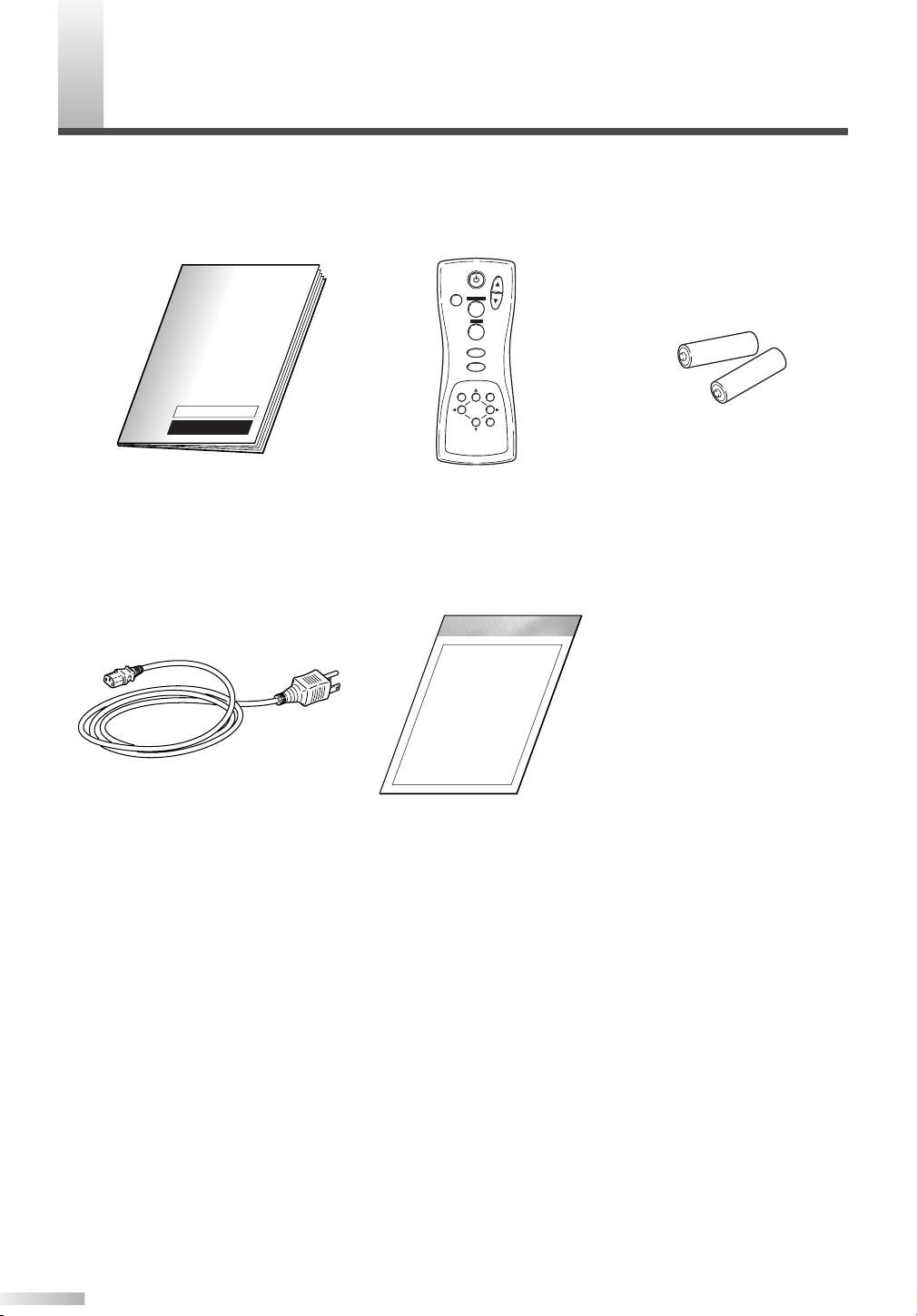
This product comes with the following accessories:
Please confirm that they are included.
P Owner's Manual
(0EMN02415)
P Power cable
(WBC0202H0001)
P Remote Control
(NE801UD)
P Set Up Guide
(1EMN20006)
NOTE
If any of these accessories are missing, please contact your dealer.
P AA batteries x 2
6
Page 7
NSERTING THE REMOTE CONTROL BATTERIES
POWER
INPUT SELECT
DISPLAY
MENU
PREVIOUS
SLEEP
VOL
MUTE
SCREEN MODE
STILL
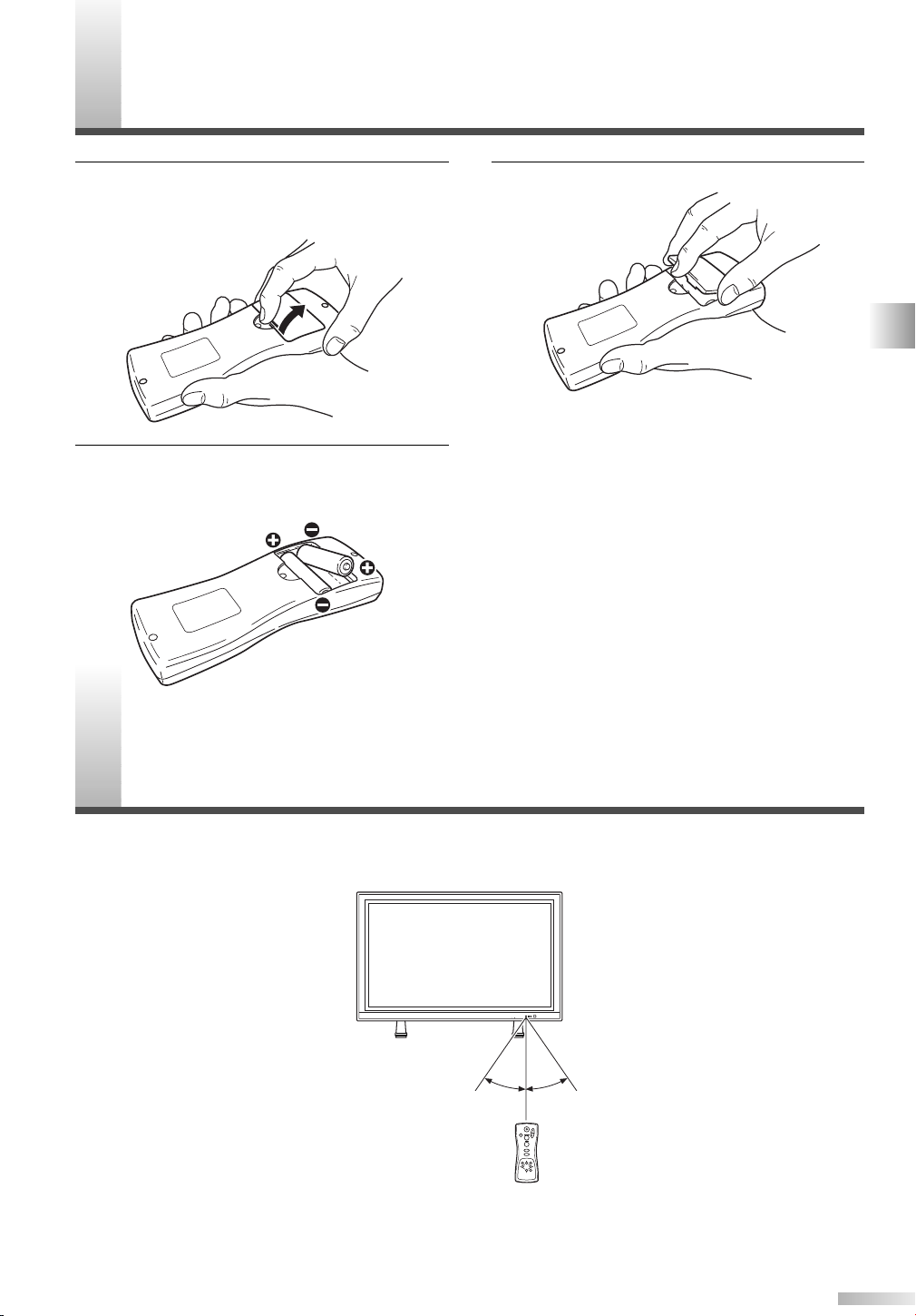
With in 30 degreesWith in 30 degrees
Approximately
7.6 yds (7 m)
Approximately 5.5 yds (5 m)Approximately 5.5 yds (5 m)
VOLUME
INPUT SELECT
STANDBY
ON POWER
I
1 Remove the back cover of the remote control
while pressing the tab on the back cover down
with your finger.
Insert two AA size batteries, making sure that
2
the polarities of the batteries match the symbols inside the remote control.
3 Replace the back cover of the remote control.
NOTE
• Do not insert a mix of old and new batteries.
• Do not insert a mix of different brands of batteries,
or different types of batteries.
• Always use new, fresh batteries as replacement.
• Never attempt to charge, heat, burn, or take apart
batteries.
EMOTE CONTROL RANGE
R
Operate the remote control within a 30 degree angle on both sides of the infrared sensor on the main
unit. You can operate the remote control from a distance of several yards away from the main unit.
NOTE
Other devices which use infrared beams, sunlight, fluorescent lights, etc., may affect the range and effectiveness
of the remote control. Make sure the plasma display is positioned in a place which minimizes interference from
them.
SUPPLIED ACCESSORIES / INSERTING THE REMOTE CONTROL BATTERIES / REMOTE CONTROL RANGE
7
Page 8
OMPONENT NAMES
VOLUME
INPUT SELECT
STANDBY
ON POWER
VOLUME
INPUT SELECT
STANDBY
ON POWER
1
2
3
4
Infrared Sensor
5
Input Terminals
Input Terminals
R L Y Cb Cr
RLYPbPr
AUDIO
COMPONENT 1
COMPONENT 2
VIDEO1AUDIO S-VIDEO1
LR
R
L
AUDIO OUT
AC IN
AUDIO
VIDEO2
S-VIDEO2
R
L
6 7 8 9
8
C
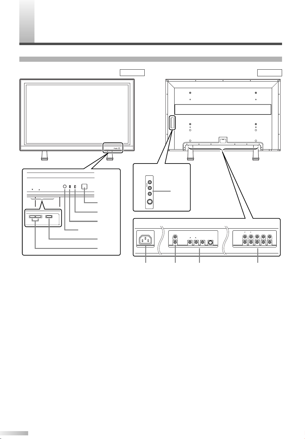
MAIN UNIT
Front Rear
Figure 2
Figure 3
1 POWER button: Turns the power ON or
STANDBY.
2 ON indicator: Lights up when the power is
ON.
3 STANDBY indicator: Lights up when the
power is in the standby mode. Disappears
when the power is ON.
4 INPUT SELECT button: Selects input termi-
5 VOLUME
6 AC IN terminal: Connect the supplied power
7 AUDIO OUT: Output terminals for audio.
8
nals.
Increases or decreases the volume.
K
(up) / L(down) button:
cable for a standard AC outlet.
8 AUDIO/VIDEO/S-VIDEO: Input terminals for
an audio and video signal. You can select
either VIDEO or S-VIDEO.
9 COMPONENT: Input terminals for a compo-
nent signal. You can make a Y-Cb-Cr interlaced connection to component 1 or Y-Pb-Pr
progressive or interlaced connection to component 2.
Page 9
REMOTE CONTROL
POWER
INPUT SELECT
DISPLAY
MENU
PREVIOUS
SLEEP
VOL
MUTE
SCREEN MODE
STILL
1
2
3
4
5
6
7
8
9
10
11
Figure 4
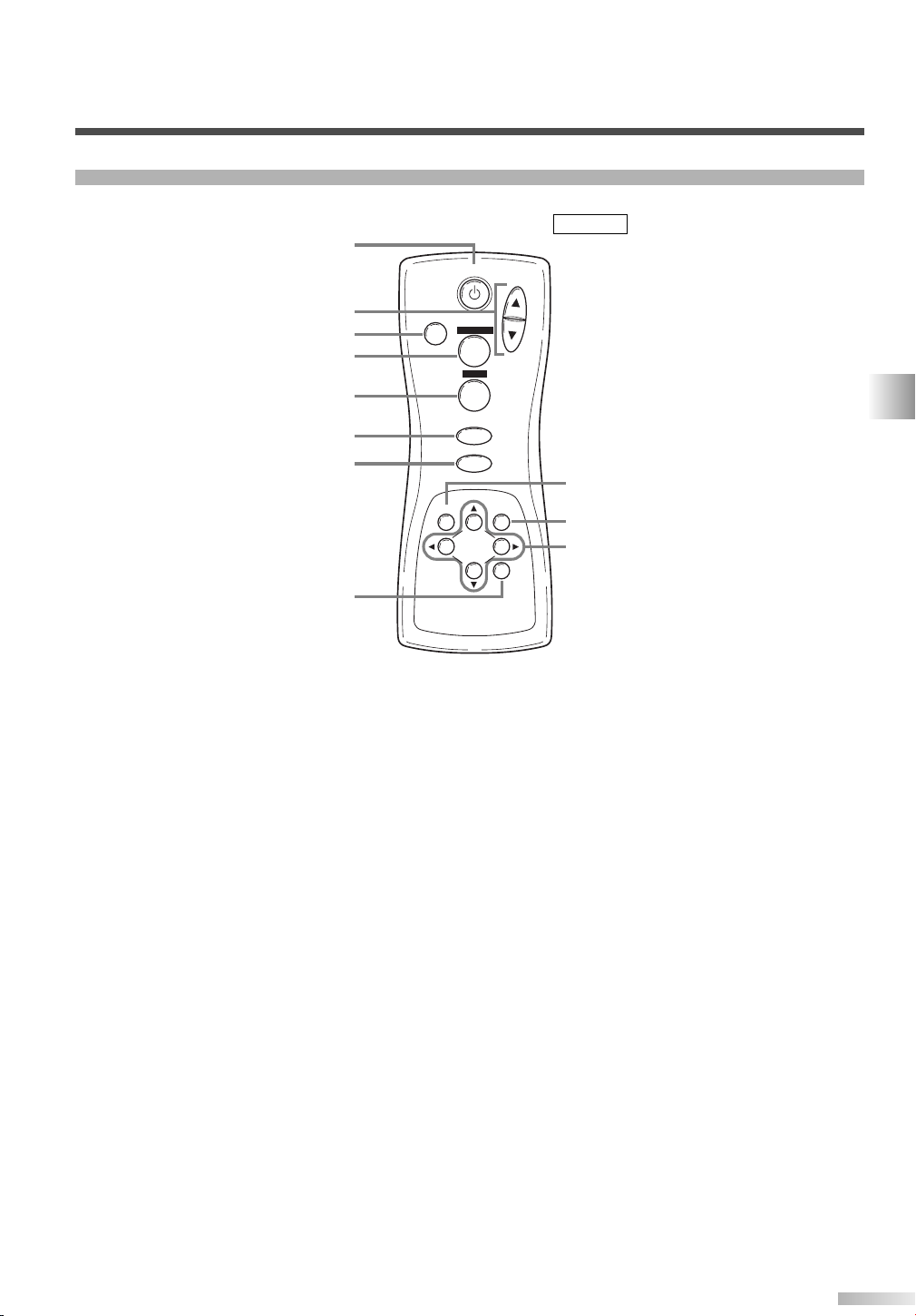
COMPONENT NAMES
1 POWER button: Turns the main power ON
or STANDBY.
2 VOL
K
(up) / L(down) button: Increases or
decreases the volume.
3 MUTE button: Turns the audio off.
4 SCREEN MODE button: Selects aspect
ratios available for the screen.
5 STILL button: Pauses the image shown on
the screen.
6 INPUT SELECT button: Selects input termi-
nals.
7 DISPLAY button: Displays the name of the
selected input terminal on the screen.
8 SLEEP button: Sets the sleep timer.
9 MENU button: Accesses the setup menu,
allowing you to access various settings.
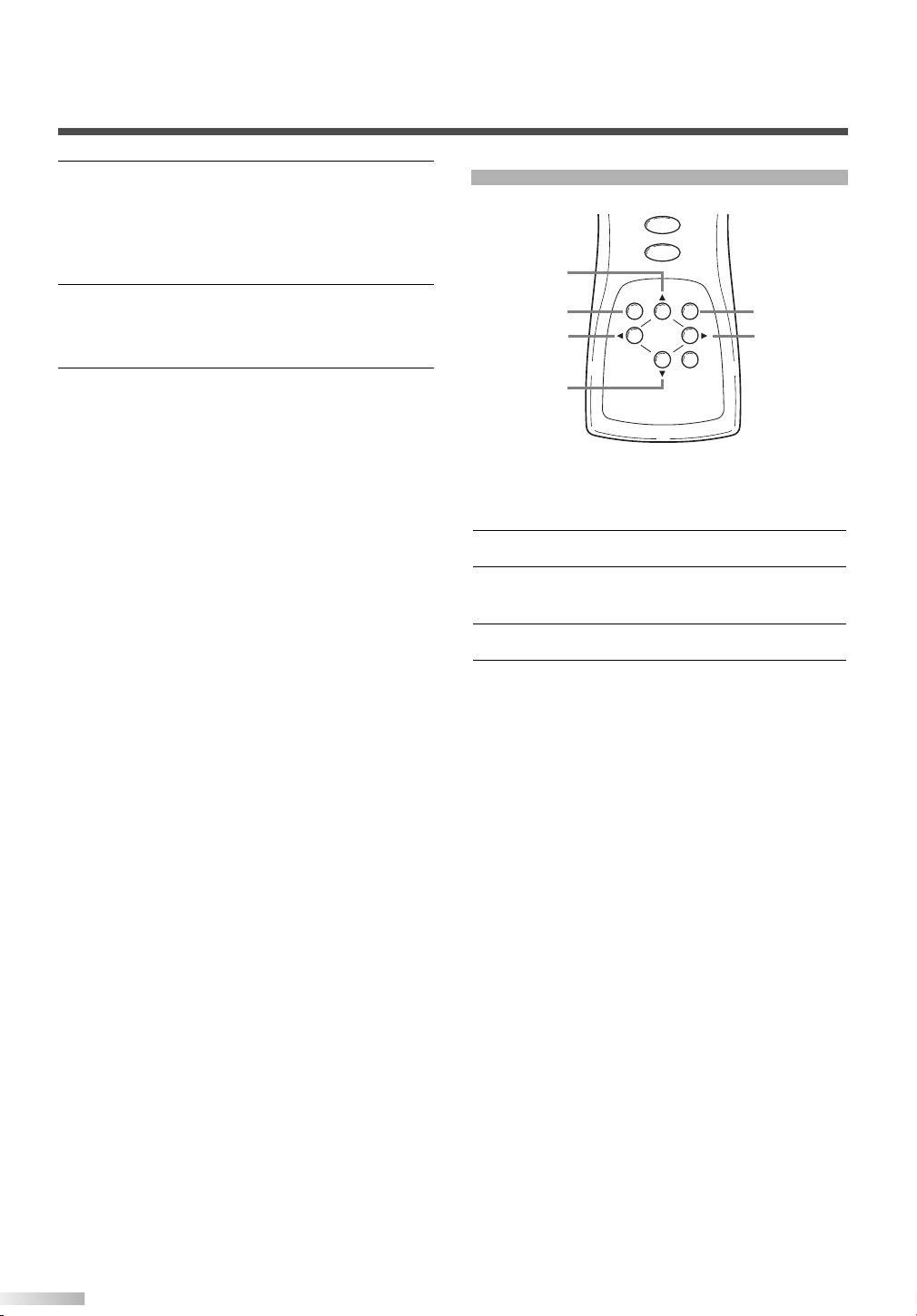
10
PREVIOUS button: Moves up one level in
the setup menu.
K
11
(up) / L(down) button: Selects the various
modes in the setup menu.
{(left) / B(right) button: Selects and
adjusts levels for the various settings.
B(enter) button: Also used as the enter
button.
9
Page 10
PERATING THE PLASMA DISPLAY
POWER
INPUT SELECT
DISPLAY
VOL
MUTE
SCREEN MODE
STILL
POWER
INPUT SELECT
O
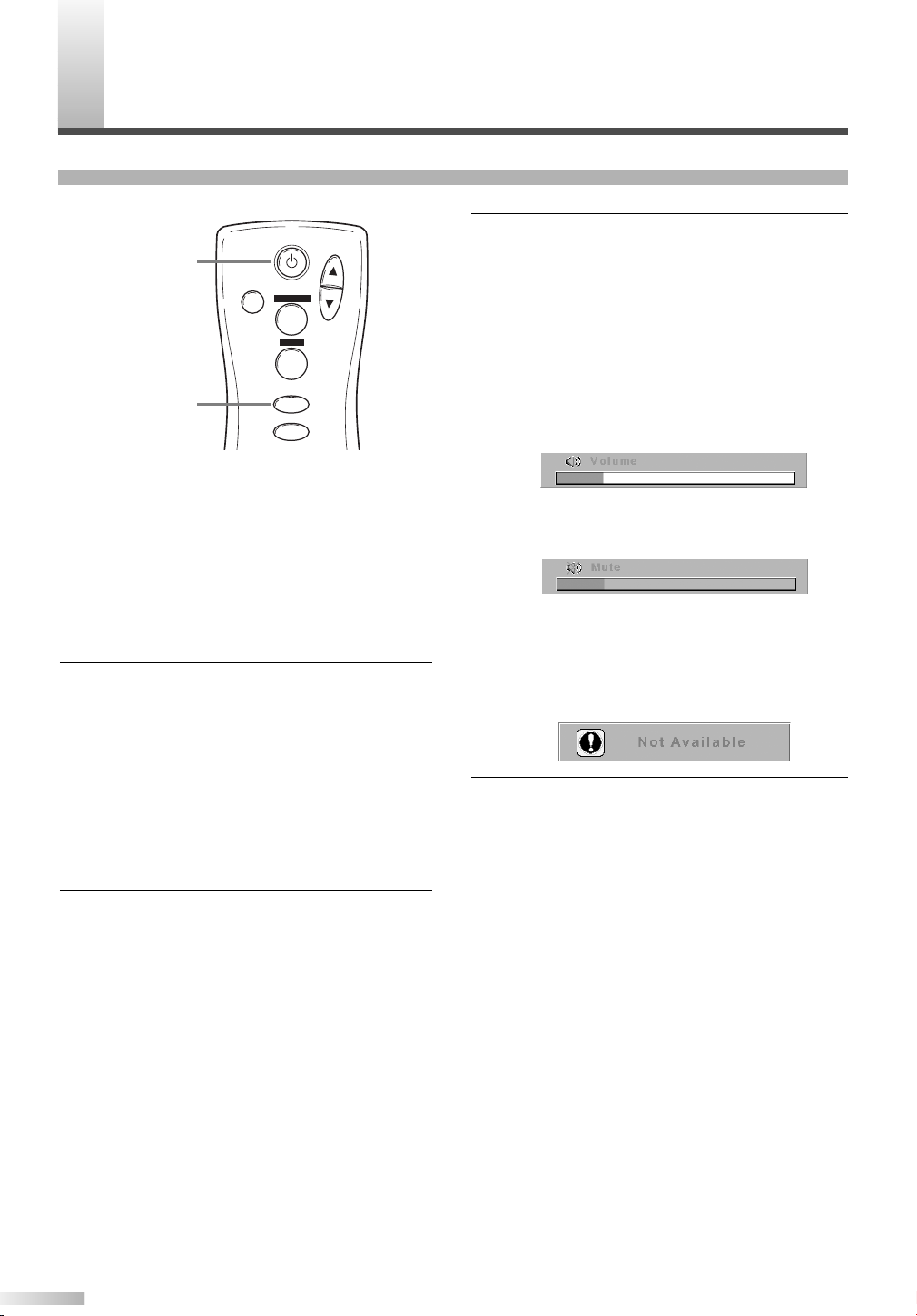
BASIC OPERATIONS
3 Adjust the volume and screen size according
to your requirements.
Perform adjustments to the volume (VOL K/
button), screen aspect ratio (SCREEN MODE
button), and picture settings (MENU button)
NOTE:
• When you adjust the volume with the VOL K/
button, a message such as the following is displayed on the screen. This message disappears
approximately 4 seconds after performing adjustments.
L
L
The following is a simple explanation of the procedure for turning the power of the display ON or
STANDBY, and the procedure for selecting the
input signal.
The procedure described here is for the remote
control, however the POWER, INPUT SELECT,
and VOLUME buttons on the plasma display can
also be used in the same way.
1 Press the POWER button.
Confirm that the STANDBY indicator is lit
before pressing the POWER button.
The power turns ON, and the ON indicator on
the main unit lights up. The STANDBY indicator on the main unit disappears.
NOTE:
• It takes approximately 8 seconds for the screen to
display after turning the power ON, but this is not
a malfunction.
Select the input signal by pressing the INPUT
2
SELECT button.
Each time you switch the input, the name of
the selected input terminal is displayed on the
screen for approximately 4 seconds.
NOTE:
• "No signal" is displayed on the screen if there is
no input from the selected terminal and there is
no message currently displayed on the screen for
volume adjustment or the setup menu, etc.
• If there is no video signal, and there has been no
operation from the remote control or the buttons
on the main unit for more than 15 minutes, the
auto shut-off function activates, switching the
plasma display to standby mode.
• If you turn the audio mute on, a message slowly
flashes on the screen. At this time, if you press
another button, this flashing stops.
• To turn the audio mute off, either press the MUTE
button again, or press the VOLK/Lbutton.
• If you press either the PREVIOUS, K, L, B, or {
button in a mode apart from the image adjustment
mode. A message such as the following is displayed.
4 Press the POWER button to turn the power
STANDBY.
The ON indicator on the main unit disappears,
and the STANDBY indicator lights up.
NOTE:
• You cannot turn the power ON for approximately 3
seconds after the power enters the standby mode.
Do not turn the power STANDBY and then ON
again in a short time interval.
• Even if the power is turned STANDBY, the main
unit is in the standby mode. In order to shut the
main power of the display OFF, it is necessary to
remove the AC cord from the power outlet.
10
Page 11

POWER
INPUT SELECT
DISPLAY
VOL
MUTE
SCREEN MODE
STILL
INPUT SELECT
DISPLAY
SELECTING THE INPUT SIGNAL
Video 1
(S-Video 1)
Video 2
(S-Video 2)
Component 1
Component 2
The procedure for selecting the input signal
described here is for use with the remote control.
However, the INPUT SELECT button on the plas-
ma display can also be used in the same way.
Displaying the Current Input Signal
Press the DISPLAY button.
1
The name of the current input terminal is displayed on the screen.
2 To clear the name of the current input terminal,
press the DISPLAY button again, or wait for
approximately 4 seconds.
NOTE:
• To redisplay the name of the input terminal, press
the DISPLAY button again.
Selecting the Input Signal
1 Press the INPUT SELECT button to select the
input signal.
Each time you switch the input signal, the
name of the selected input terminal is displayed on the display for approximately 4 seconds.
The INPUT SELECT button cycles through the
input terminals in the following pattern:
NOTE:
• When switching the input signal, audio mute turns
ON temporarily.
• S-VIDEO1 takes preference over the VIDEO 1
jack, as does S-VIDEO 2 over the VIDEO 2 jack.
Therefore, if there is input to the VIDEO and SVIDEO terminals at the same time, the S-VIDEO
signal is displayed on the screen. If the S-VIDEO
cable is not connected to the plasma display, the
VIDEO signal will be displayed on the screen.
• 480i (interlaced) signals can be connected to the
COMPONENT 1 and 2 terminals. Any of the following display formats: 480i, 480p (progressive),
1080i, and 720p (progressive) signals can be connected to the COMPONENT 2 terminal. If one of
these video signals is detected, the format of the
input signal is displayed after the name of the current input terminal, as in the following manner.
OPERATING THE PLASMA DISPLAY
• A "No signal" message appears if there is no video
signal, and there is no message currently displayed on the screen for volume adjustment or the
setup menu, etc. If there continues to be no video
signal for more than 10 seconds, "No signal" slowly moves around the screen.
• If there is no video signal, and there has been no
operation from the remote control or the buttons
on the main unit for more than 15 minutes, the
auto shut-off function activates, and the display
switches to standby mode.
11
Page 12

OPERATING THE PLASMA DISPLAY
POWER
INPUT SELECT
DISPLAY
VOL
MUTE
SCREEN MODE
STILL
SCREEN MODE
CHANGING THE ASPECT RATIO (SCREEN MODE)
Each time you change the screen mode, the
name of the selected mode is displayed on the
screen for approximately 4 seconds.
The SCREEN MODE button switches between
the screen modes in the following pattern.
NOTE:
• When switching the input signal, the audio mute
turns ON temporarily.
By changing the aspect ratio of the screen you
can select the manner in which you wish to view
the picture.
Press the SCREEN MODE button to display
1
the current screen mode.
Press the SCREEN MODE button a second
2
time to change the screen mode.
• You can only select the "Normal" and "Zoom"
screen modes for 1080i and 720p video signals
connected to the COMPONENT 2 terminal.
ZoomNormal Full Wide
Mode
Normal
Full
Wide
Zoom
12
Normal
Full
Wide
Zoom
Picture
Explanation
Normal will display a 4:3 picture at its standard 4:3 size.
For 1080i and 720p video signals, a picture will be displayed
at 16:9 size.
Full will display a 4:3 picture at a 16:9 size, with horizontal
elongation necessary to fill the screen.
Wide will display a 4:3 picture at a 16:9 size, with less
horizontal elongation necessary to fill the screen because a
little bit of the top and bottom will be cut off.
Zoom will magnify the entire 4:3 picture to fill the screen, with
no horizontal elongation to fill the screen, as more of the top
and bottom are cut off. Use this mode to view letterboxed 4:3
picture content to get a widescreen picture. A 16:9 picture will
be magnified similarly, but to a lesser extent.
Page 13

POWER
INPUT SELECT
DISPLAY
VOL
MUTE
SCREEN MODE
STILL
STILL
STILL
INPUT SELECT
DISPLAY
MENU
PREVIOUS
SLEEP
SLEEP
0 minutes 10 minutes 90 minutes
SLEEP
You can freeze the image displayed on the
screen.
Press the STILL button.
1
The still mode turns on, and the image displayed on the screen is frozen.
NOTE:
• When the still mode is on, the message "Still"
slowly flashes on the screen.
• When the still mode is on, the audio is muted.
• You cannot turn the still mode on when there is no
video signal or when switching between video signals.
Press the STILL button again to turn the Still
2
mode off.
NOTE:
• You can also press the INPUT SELECT,
DISPLAY, SLEEP, VOLK(up) / L(down), MUTE,
SCREEN MODE, or MENU buttons to turn the still
mode off.
You can select the sleep timer.
Press the SLEEP button.
1
The sleep timer is displayed on the screen.
NOTE:
• If the sleep timer is activated, the remaining time
is displayed on the screen.
If not activated, “0 minutes” is displayed.
Press the SLEEP button to set the time.
2
The SLEEP button switches between the
times.
The timer starts counting down after the message displaying the set time disappears (after
approximately 4 seconds).
NOTE:
• The remaining time displayed for the sleep timer
changes in steps of 1 minute.
• To change the set time, repeat the above procedure.
OPERATING THE PLASMA DISPLAY
13
Page 14

OPERATING THE PLASMA DISPLAY
MAIN MENU
Picture select
Picture mode
Window setting H-Position
English
Français
Español
V-Position
Language
Manual
Brightness
Contrast
Color
Tint
Sharpness
Color temp.
Normal
Reset
News
Sport
Cool
Warm
Movie
Detail Screen saver Back ground
Opaque Translucent
Off
Slow Fast
NAVIGATING THE SET UP MENU
In the setup menu, you can specify settings for picture adjustment, picture position, language, screen
saver, and background.
NOTE:
If you do not press any buttons for approximately 20 seconds, the display automatically exits the menu mode.
Layout of the Setup Menu
The various functions in the setup menu are outlined below:
14
Page 15

INPUT SELECT
DISPLAY
MENU
PREVIOUS
SLEEP
MENU
ENTERING THE MAIN MENU
INPUT SELECT
DISPLAY
MENU
PREVIOUS
SLEEP
MENU
B
PREVIOUS
K
L
PICTURE SELECT
Press the MENU button.
1
The display enters the main menu, and the
MAIN MENU is displayed on the screen.
NOTE:
• If you press the PREVIOUS button or the MENU
button on the MAIN MENU, the menu is cancelled.
• For procedures which use the ENTER button, use
the B button as the ENTER button.
1 Enter the main menu with the MENU button.
“Picture select” is selected on the MAIN
MENU.
Press the B (ENTER) button.
2
The PICTURE SELECT menu is displayed on
the screen.
NOTE:
• Press the PREVIOUS button to return to the MAIN
MENU. Pressing the MENU button cancels the
menu.
• Picture select display will disappear from the TV
screen automatically after about 20 seconds if you
do not press any buttons.
OPERATING THE PLASMA DISPLAY
15
Page 16

OPERATING THE PLASMA DISPLAY
INPUT SELECT
DISPLAY
MENU
PREVIOUS
SLEEP
MENU
B{
PREVIOUS
K
L
Automatically Adjusting the Picture
Settings
Manually Adjusting the Picture Settings
1 Select "Picture mode" on the PICTURE
SELECT screen with the K/Lbuttons.
Select "Manual" with the { / B buttons.
2
The display enters the manual mode, and you
can specify individual adjustments.
Select the mode to adjust with the K/Lbut-
3
tons.
The modes rotate in the following order:
"Picture mode" - "Brightness" - "Contrast" - ..
...- "Reset" - "Picture mode"
1 Select "Picture mode" on the PICTURE
SELECT screen with the K/Lbuttons.
2 Select the automatic adjustment mode accord-
ing to the type of picture displayed on the
screen with the { / B buttons.
NOTE:
• There are 3 modes for automatically adjusting the
picture settings; "News", "Movie", and "Sport".
• MANUAL refers to manual picture settings adjustment.
3 Press the PREVIOUS button to return to the
MAIN MENU.
NOTE:
• Pressing the MENU button cancels the menu.
4 Adjust the selected mode using the { / B but-
tons.
NOTE:
• If you have selected Brightness, Contrast, Color,
Tint, or Sharpness, the menu display disappears,
and a bar for adjusting the selected mode
appears in the center of the bottom of the screen.
• You can select "Color temp." from among three
modes: "Normal", "Warm", and "Cool".
• If you select "Reset", and press the B (ENTER)
button, the adjusted values return to their initial
settings.
To adjust a different mode, repeat steps 3 and
5
4.
6 Press the PREVIOUS button to return to the
Picture mode.
NOTE:
• Pressing the MENU button cancels the menu.
16
Page 17

DISPLAY
MENU
PREVIOUS
SLEEP
B{
K
L
MENU
Initializing the Adjustments
1 Select "Reset" on the PICTURE SELECT
screen with the K/Lbuttons.
Press the B (ENTER) button.
2
The settings you specified individually are initialized (return to their default factory settings)
NOTE:
• The default factory settings are as follows:
PICTURE MODE: MANUAL
BRIGHTNESS: 50/100
CONTRAST: 70/100
COLOR: 50/100
TINT: 50/100
SHARPNESS: 1/2
COLOR TEMP.: NORMAL
WINDOW SETTING
You can move the picture displayed on the screen
up, down, left or right.
Enter the main menu with the MENU button.
1
2 Select "Window setting" on the MAIN MENU
screen with the K/Lbuttons.
If there is no input from a video signal, "Window
setting" is grayed out, and you cannot select it.
OPERATING THE PLASMA DISPLAY
3 Press the B (ENTER) button.
The "WINDOW SETTING" menu is displayed
on the screen.
17
Page 18
OPERATING THE PLASMA DISPLAY
DISPLAY
MENU
PREVIOUS
SLEEP
B{
PREVIOUSMENU
K
L
Select the mode to adjust with the K/Lbut-
4
ton.
Select "H-Position" to move the picture horizontally (left or right), and select "V-Position" to
move the screen vertically (up or down).
5 Adjust with the { / B buttons.
The { / B buttons are also used for moving
the picture vertically.
6 Press the PREVIOUS button to return to the
MAIN MENU.
NOTE:
• Pressing the MENU button cancels the menu.
SWITCHING THE DISPLAY LANGUAGE
You can select the language displayed on the
screen from English, French, and Spanish.
Enter the main menu with the MENU button.
1
2 Select "Language" on the MAIN MENU screen
with the K/Lbuttons.
3 Select the language with the { / B buttons.
Press the PREVIOUS button to return to the
4
MAIN MENU.
NOTE:
• Pressing the MENU button cancels the menu.
18
Page 19

SETTING THE SCREEN SAVER AND THE BACKGROUND COLOR
DISPLAY
K
MENU
PREVIOUS
PREVIOUSMENU
SLEEP
B{
L
You can specify settings for the screen saver and
the background color.
Enter the main menu with the MENU button.
1
2 Select "Detail" on the MAIN MENU screen
with the K/Lbuttons.
3 Press the B (ENTER) button.
The "DETAIL" menu is displayed on the
screen.
Setting the Screen Saver
1 Select "Screen saver" on the DETAIL screen
with the K/Lbuttons.
Select the mode with the { / B buttons.
2
NOTE:
• There are 3 modes for the screen saver; "Off",
"Slow", and "Fast".
"Slow" moves 1 pixel every 30 minutes, and "Fast"
moves 1 pixel every 10 minutes. This prevents
images burning into the screen.
• When a 480i or 1080i input signal connected to
the COMPONENT 2 terminal is displayed, the vertical movement is different.
"Slow" moves 2 pixels every 60 minutes, and
"Fast" moves 2 pixels every 20 minutes.
3 Press the PREVIOUS button to return to the
MAIN MENU screen.
NOTE:
• Pressing the MENU button cancels the menu.
Setting the Background Color
1 Select "Background" on the DETAIL screen
with the K/Lbuttons.
NOTE:
• Press the PREVIOUS button to return to the
MAIN MENU. Pressing the MENU button cancels
the menu.
Select the mode with the { / B buttons.
2
Select "Opaque" or "Translucent" for the background color.
Press the PREVIOUS button to return to the
3
MAIN MENU screen.
NOTE:
• Pressing the MENU button cancels the menu.
OPERATING THE PLASMA DISPLAY
19
Page 20

XTERNAL INPUT TERMINALS
RLYCbCr
RLYPbPr
AUDIO
COMPONENT 1
COMPONENT 2
VIDEO1AUDIO S-VIDEO1
LR
R
L
AUDIO OUT
AUDIO
VIDEO2
S-VIDEO2
R
L
AV Input Terminals
VIDEO 2
S-VIDEO 2
See page 21.
AV Input Terminals
VIDEO 1
S-VIDEO 1
See page 21.
Audio Output Terminals
AUDIO OUT
See page 23.
Component Input Terminals
COMPONENT 1
COMPONENT 2
See page 22.
E
The following input terminals are available.
In order to view television, it is necessary to connect a tuner device (example: cable box, satellite box,
DTV, etc.) to the plasma display.
20
Page 21

CONNECTING DEVICES TO THE AV INPUT TERMINALS
AUDIO
S-VIDEO
2×RCA
audio cables
Audio
OUT
Video
OUT
S Video
OUT
RL
(DVD Player)
Example of input signal source
(VCR)
(Cable/Sat STB)
(Camcorder)
AUDIO
VIDEO2
S-VIDEO2
R
L
Antenna or
cable signal
Antenna, cable,
satellite signal
VIDEO1AUDIO S-VIDEO1
LR
Video input to
S-VIDEO socket
Audio input to
L/R sockets
Video input to
S-VIDEO socket
Audio input to
L/R sockets
AUDIO-VIDEO
3×RCA audio
video cables
Video input to
RCA socket
Video input to
RCA socket
Audio input to
L/R sockets
Audio input to
L/R sockets
Audio
OUT
Video
OUT
S Video
OUT
RL
(DVD Player)
Antenna or
cable signal
Antenna, cable,
satellite signal
Example of input signal source
(VCR)
(Cable/Sat STB)
(Camcorder)
AUDIO
VIDEO2
S-VIDEO2
R
L
VIDEO1AUDIO S-VIDEO1
LR
Connect the output of the device to the input terminals of plasma display as shown in the following illustrations.
NOTE
• You will select TV channels with the VCRs, or Cable/Satellite set top box that will be viewed on the plasma display.
• Cables shown here are not included with the plasma display.
VIDEO Signal Connection (Basic Signal Transfer)
S-VIDEO Signal Connection (Better Signal Transfer)
EXTERNAL INPUT TERMINALS
21
Page 22

EXTERNAL INPUT TERMINALS
AUDIO
2×RCA
audio cables
RLYCbCr
RLYPbPr
AUDIO
COMPONENT 1
COMPONENT 2
R
3×RCA
video cables
(Example: DVD Player)
Y, Cb, Cr
L Y CBC
R
Antenna, cable,
satellite signal
PrPbY
2×RCA audio cables
(Example:
Set Top Box for DTV)
AUDIO
R L Y PBP
R
RLYCbCr
RLYPbPr
AUDIO
COMPONENT 1
COMPONENT 2
CONNECTING DEVICES TO THE COMPONENT INPUT TERMINALS
Connect the output of the device to the input terminals of the plasma display as shown in the following
illustrations.
NOTE
• When connecting a 480i input signal, connect it to COMPONENT 1.
• Cables shown here are not included with the plasma display.
• Use COMPONENT 2 for 480i, 1080i (interlaced), 480p, 720p (progressive) video signals.
Component 1 Signal (Y, Cb, Cr) Connection (Best Signal Transfer)
480i (interlaced) signals can be connected to Component 1.
Component 2 Signal (Y, Pb, Pr) Connection (Best Signal Transfer)
480i, 480p (progressive), 1080i, and 720p (progressive) signals can be connected to Component 2.
NOTE
22
You will select TV channels with the box that will be seen on the plasma display.
Page 23

CONNECTING PLASMA DISPLAY TO AUDIO SYSTEM
AUDIO
2×RCA
audio cables
R
L
TV
AUDIO IN
VIDEO AUX
(Example: Amplifier/Receiver)
Audio output
to L/R sockets
R
L
AUDIO OUT
NOTE
Cables shown here are not included with the plasma display.
AUDIO Signal Connection
Connect the AUDIO OUT from the plasma display to the AUDIO IN on the amplifier/receiver.
EXTERNAL INPUT TERMINALS
23
Page 24

ONNECTING THE POWER CABLE
C
Connect the power cable to the plasma display after connecting the input terminals.
AC IN
2
1
1 Connect the power cable to the plasma display
first.
Connect the power cable to an AC outlet.
2
#
CAUTION
• Do not connect the power cable to a power
supply outside the indicated voltage of the
plasma display (AC 120V). Connecting the
power cable to a power supply outside of this
range may result in fire or electrical shocks.
• Always use the power cable included with the
plasma display. Do not use any other cable.
For safety, make sure to always connect the
power cable to a three pronged AC outlet.
24
Page 25

2
2
1
TTACHING A WALL MOUNT BRACKET
2
Stand
Plasma Display rear
1
1
A
(SOLD SEPARATELY)
The following is a description of the method for attaching a wall mount to the plasma display.
When performing this operation, refer to the instruction manual included with the wall mount
kit.
#
CAUTION
• Any damage caused by incorrectly attempting to mount the plasma display is not covered under the
terms of the manufacturers warranty.
1 Turn the plasma display over and place it
screen-first onto a table which has a soft cloth
draped over it.
Place the plasma display in a way so that the
stands hang over the edge of the table.
NOTE:
• Make sure to use a table which can support the
weight of the plasma display, and is larger than
the plasma display.
• Make sure the table is in a stable location.
3 Attach the left and right TV rails to the plasma
display using the M8 screws included with the
wall mount kit.
indicates the position of the screw holes on
the plasma display
NOTE:
• Only use the screw holes indicated by for
mounting the plasma display.
• For instructions on how to attach the TV rails, refer
to the instruction manual included with the mount
wall kit.
2 Remove the stands from the plasma display.
Unscrew the M5 screws indicated by , and
remove the left and right stands.
NOTE:
• The screws and stands you have removed are
necessary for reattachment at a later date. Make
sure to keep them in a safe place.
4 Attach the plasma display to the wall.
NOTE:
• Refer to the instruction manual included with the
wall mount when securing the plasma display to
the wall.
CONNECTING THE POWER CABLE / ATTACHING A WALL MOUNT BRACKET (SOLD SEPARATELY)
25
Page 26

AINTENANCE
M
CLEANING THE PLASMA DISPLAY
Always unplug the plasma display from the AC
outlet before cleaning.
Clean the case of the plasma display with a soft
cloth which has been wet and wrung dry.
If the screen of the plasma display is dirty or
dusty, wipe it clean with a soft cloth.
ARNING
W
NOTE
Never use a solvent, alcohol, or any other abrasive
liquid to clean the plasma display.
Always make sure the area around vents on the plasma display is clear and clean. Failure to do this may
result in fire or cause the plasma display to fail prematurely.
Preventing Image Burn on the plasma display
Fixed images displayed on the plasma display for an extended period of several hours may cause
uneven pixel aging causing damage to the plasma display. The screensaver mode helps reduce this
phenomenon, but in general you should to try avoid displaying fixed images for extended periods on
the plasma display.
Images of high luminance displayed on the plasma display for more than 60 seconds may cause lingering images to remain on the screen. These images will automatically disappear, but may take
time depending on the luminance of the images and how long they were displayed on the screen.
26
Page 27

ROUBLESHOOTING GUIDE
T
•IGNITION NOISE:
Black spots or horizontal streaks may appear, picture may flutter or drift.
Usually caused by interference from automobile ignition systems, neon
lamps, electrical drills, and other electrical appliances.
•GHOSTS:
Ghosts are caused by the television signal following two paths. One is the
direct path and the other is reflected from tall buildings, hills or some
other objects. Changing the direction or position of the antenna may
improve reception. Ghosting may also be caused by defects in the
antenna system such as unshielded leads or connecting several sets to
the same antenna without using multiple antenna couplers.
Ghosting occurring when the plasma display is connected to a cable TV
system may indicate a bad cable wire or loose connection. Confirm that
the cable wire is properly connected.
•SNOW:
If your receiver is located in the fringe area of a television station where
the signal is weak, your picture may be marred by the appearance of
small dots. When the signal is extremely weak, it may be necessary to
install a special antenna to improve the picture.
Snowing occurring when the plasma display is connected to a cable TV
system may indicate a bad cable wire or loose connection. Confirm that
the cable wire is properly connected.
Vertical stripes appear,
depending on the screen
contents.
•RADIO FREQUENCY INTERFERENCE:
The interference produces moving ripples or diagonal streaks, and in
some cases, causes loss of contrast in the picture.
•PREVENTION OF AN OBSTACLE TO RADIO RECEIVERS
This monitor has been designed pursuant to the FCC class B Rules. This
is to prevent a problem to Radio receivers. lf this monitor causes a
problem to Radio receivers, then take the following steps:
-Keep the monitor away from Radio.
-Adjust Radio antennas in order for the monitor not to receive
interference.
-The antenna cable of Radio should be kept away from the monitor.
-Use a coaxial cable for antenna.
You can check if this monitor influences Radio receivers by turning off all
other equipment other than the monitor.
If you find a problem receiving Radio when using the monitor, check the
instructions mentioned above.
•The plasma display panel is lighting the phosphors by the discharge of
internal radiation. Depending on the screen contents, in rare cases this
may cause vertical stripes to appear because of failure to light. Please
note that this is not a malfunction.
MAINTENANCE / WARNING / TROUBLESHOOTING GUIDE
27
Page 28

TROUBLESHOOTING GUIDE
CHECK THESE ITEMS AND
TRY THESE CORRECTIONS
Be sure external connections are correct.
Be sure power cable is plugged in.
Be sure PANEL is power switched "ON"
Check for local interference
Adjust Contrast control
SYMPTOM
Remote control does not work
No picture, no sound
Sound OK, picture poor
Picture OK, sound poor
Picture blurred
Weak Picture
Lines or streaks in picture
Picture rolls vertically
No color
Poor picture
Irregular dots on the screen
Adjust Bright control
Adjust Color control
Adjust Tint control
Adjust Volume control
Check batteries in Remote control
It is a characteristic of a Plasma Display.
About Interference to Infrared Devices
Please note in advance that using other infrared devices (such as infrared cordless headphones)
near the plasma display may cause infrared interference to occur.
About Pixel Defects
A plasma display is created by using a collection of miniature pixels. It is possible to display more
than 99.99% of valid pixels, however a small fraction of pixels over the life of the product may not
illuminate or may constantly be illuminated.
This is not to be considered a defect in the plasma panel.
28
Page 29

PECIFICATIONS
S
Display Features
TypePlasma panel
Screen Size 42 in. Wide VGA panel
Pixel Resolution 852 (H) x 480 (V)
Output Colors 16.7 million
Screen Aspect Ratio 16:9
Viewing Angle 160 degrees
Contrast Ratio 1000:1
Brightness 400 cd/m2(PEAK)
Comb Filter Type 3-Dimensional Y/C Separation
Available Input Format 720p/1080i/480p/480i (720p/1080i/480p: Component 2 only)
Audio Features
Sound Output 5W + 5W, 10% THD
Speaker 2.8 in x 1.6 in Oval Type x 2
Additional Features
Screen Saver Off/Slow/Fast
Trilingual OSD English/Spanish/French
Color Temperature Select Cool/Normal/Warm
AV Memory Manual/News/Movie/Sport
Widescreen Modes 4:3 Standard, Full, Wide, Zoom
Sleep Timer 90 minutes
Wall Mount Kit Ready For VMPLs, SANUS SYSTEMS
Connectors
Component AV Input (1) SD component video/Y, Cb, Cr (RCA x 3) - rear
audio L/R (RCA x 2) - rear
Component AV Input (2) HD component video/Y, Pb, Pr (RCA x 3) - rear
audio L/R (RCA x 2) - rear
Composite AV Input (1) Composite video ( RCA x 1 ) - rear
S-Video (1) S-Video (4 pin DIN ) - rear
audio L/R (RCA x 2) - rear
Composite AV Input (2) Composite video ( RCA x 1 ) - side
S-Video (2) S-Video (4 pin DIN ) - side
audio L/R (RCA x 2) - side
Analog Audio output audio L/R (RCA x 2) - rear
General
Power In 120V ±10%, 60Hz/AC
Power Consumption 350 W (Standby: 0.8W)
Exterior Color Silver & Black
Dimension
Weight 94.8 lbs (43 kg)
(Incl. stand) (Width x Height x Depth)
41 1/2 x 28 3/4 x 13 in. (1054 x 730 x 330 mm)
NOTE
The specifications and design of this product are subject to change without notice.
As an ENERGY STAR Partner, our company has determined that this product meets
the E
NERGY STAR guidelines for energy efficiency. ENERGY STAR is a U.S. registered mark.
®
®
®
SPECIFICATIONS
29
Page 30

EFERENCIA RÁPIDA EN ESPAÑOL
R
Traslado de la unidad principal
Debido al considerable peso de la pantalla de plasma, se necesitan dos personas para trasladarla.
Ambas personas deben asir la parte superior de la pantalla con una mano y la base de la pantalla con la
otra mano.
Vea la Figura 1 en la página 4.
NSTALACIÓN DE LAS PILAS EN EL CONTROL REMOTO
I
Para retirar la tapa trasera del control remoto,
1
presione la lengüeta hacia abajo con un dedo.
2 Instale dos pilas tamaño AA, asegurándose de
que la polaridad de las pilas coincida con los
símbolos impresos en el interior del control
remoto.
Instale la tapa trasera en el control remoto.
3
30
Page 31

OMBRES DE LOS COMPONENTES
N
UNIDAD PRINCIPAL
Vea las Figura 2 y Figura 3 en la página 8.
1 Botón POWER: Para conectar (ON) o dejar
en modo de espera (STANDBY).
2 Indicador ON: Se ilumina cuando la ali-
mentación está conectada.
3 Indicador STANDBY: Se ilumina cuando la
pantalla se encuentra en modo de espera.
Se apaga cuando se conecta la alimentación.
4 Botón INPUT SELECT: Para seleccionar
los terminales de entrada.
5 Botón VOLUME
ción): Para aumentar o disminuir el nivel de
volumen.
K
(aumento) / L(disminu-
CONTROL REMOTO
Vea la Figura 4 en la página 9.
1 Botón POWER: Para conectar (ON) o dejar
en modo de espera (STANDBY).
2 Botón VOL
Para aumentar o disminuir el nivel de volumen.
K
(aumento) / L(disminución):
6 Terminal AC IN: Conecte el cable de ali-
mentación suministrado entre este terminal
y una toma de corriente de CA estándar.
7 AUDIO OUT: Terminal de salida para audio.
8 AUDIO/VIDEO/S-VIDEO: Terminal de entra-
da para señales de audio y video. Se puede
seleccionar VIDEO o S-VIDEO.
9 COMPONENT: Terminal de entrada para
señales de componente. Es posible realizar
una conexión entrelazada para componente
1 o Y-Pb-Pr progresivo o una conexión
entrelazada para componente 2.
9 Botón MENU: Para acceder al menú de
configuración, donde se pueden hacer diversos ajustes.
10
Botón PREVIOUS: Para subir un nivel en el
menú de configuración.
REFERENCIA RÁPIDA EN ESPAÑOL / IINSTALACIÓN DE LAS PILAS EN EL CONTROL REMOTO / NOMBRES DE LOS COMPONENTES
3 Botón MUTE: Para activar o desactivar la
función de silenciamiento de audio.
4 Botón SCREEN MODE: Se utiliza para
seleccionar uno de los formatos disponibles
para la pantalla.
5 Botón STILL: Para congelar la imagen
mostrada en la pantalla.
6 Botón INPUT SELECT: Para seleccionar
los terminales de entrada.
7 Botón DISPLAY: Muestra el nombre del ter-
minal de entrada seleccionado en la pantalla.
8 Botón SLEEP: Para programar el tempo-
rizador de desconexión automática.
11
BotónK(arriba) / L(abajo): Para selec-
cionar diversos modos en el menú de configuración.
Botón
seleccionar y ajustar niveles para las diversas opciones de ajuste.
Botón
como botón de introducción.
{(izquierda) / B(derecha): Para
B(introducción): También se utiliza
31
Page 32

Registered Trademark / TM Trademark /
SM
Service Mark of Sears, Roebuck and Co.
Marca Registrada /
TM
Marca de Fábrica / SM Marca de Servicio de Sears, Roebuck and Co.
MC
Marque de commerce / MD Marque déposée de Sears, Roebuck and Co. © Sears, Roebuck and Co.
Get it fixed, at your home or ours!
Our Home
For repair of carry-in items like vacuums, lawn equipment,
and electronics, call or go on-line for the location of your nearest
Sears Parts & Repair Center.
1-800-488-1222
Call anytime, day or night (U.S.A. only)
www.sears.com
To purchase a protection agreement on a product serviced by Sears:
1-800-827-6655 (U.S.A.) 1-800-361-6665 (Canada)
Para pedir servicio de reparación
a domicilio, y para ordenar piezas:
1-888-SU-HOGAR
SM
(1-888-784-6427)
Au Canada pour service en français:
1-800-LE-FOYER
MC
(1-800-533-6937)
www.sears.ca
Your Home
For repair- in your home -of all major brand appliances,
lawn and garden equipment, or heating and cooling systems,
no matter who made it, no matter who sold it!
For the replacement parts, accessories and
owner's manuals that you need to do-it-yourself.
For Sears professional installation of home appliances
and items like garage door openers and water heaters.
1-800-4-MY-HOME
R
(1-800-469-4663)
Call anytime, day or night
(U.S.A. and Canada)
www.sears.com www.sears.ca
R
R
One Year Full Warranty
If this product experiences any failure due to a defect in material or workmanship within one year
from the date of purchase, contact Sears at 1-800-4-MY-HOME(R) to arrange to have it repaired
free of charge.
This warranty applies only if this product is used for private household purposes.
This warranty gives you specific legal rights, and you may also have other rights which vary from
state to state.
Sears, Roebuck and Co., Dept. 817WA, Hoffman Estates, IL 60179
For the location of a Sears Service Center in your area : 1-800-488-1222
Printed in Malaysia
L0600UA★★★★
0EMN02415
Page 33

documentation manual, user maintenance, brochure, user reference, pdf manual
This file has been downloaded from:
User Manual and User Guide for many equipments like mobile phones, photo cameras, monther board, monitors, software, tv, dvd, and othes..
Manual users, user manuals, user guide manual, owners manual, instruction manual, manual owner, manual owner's, manual guide,
manual operation, operating manual, user's manual, operating instructions, manual operators, manual operator, manual product,
 Loading...