

Page 1

INSTALLATION AND
OPERATION MANUAL
Vertical Multi-Port
Hot Water Boilers
Model VMP-W
40 -150 HP
Serial/ National
Board Number
Model
Fulton Order
Sold To
Job Name
Date
VMPW-IOM-2012-1001
Page 2

Page 3

VMPW-IOM-2012-1001 TABLE OF CONTENTS
Introduction 1-1
Overview .............................................................................................................. 1-2
Warnings & Cautions ............................................................................................1-2
Disclaimers and Local Codes ................................................................................1-2
Installation 2-1
Placement & Rigging ........................................................................................... 2-2
Clearances & Serviceability .................................................................................. 2-4
Environment, Ventilation and Combustion Air Requirements ............................ 2-4
Utilities .................................................................................................................2-6
THE GAS SUPPLY ..........................................................................................................................26
THE OIL SUPPLY ...........................................................................................................................27
Electrical Supply ................................................................................................... 2-8
Water Supply ........................................................................................................2-8
INSTALL WATER PIPING ...............................................................................................................28
Water Chemistry Requirements ...........................................................................2-9
PREVENT OXYGEN CONTAMINATION ........................................................................................210
ELIMINATE SYSTEM AIR ............................................................................................................210
Piping Speci cations .......................................................................................... 2-11
Insulation ........................................................................................................... 2-12
System Interfaces ............................................................................................... 2-12
FILL CONNECTION ......................................................................................................................212
Assembly of Multi-Skid Systems ........................................................................ 2-12
Stack and Flue ....................................................................................................2-13
EXHAUST SIDE WALL VENTING ................................................................................................215
Testing ................................................................................................................ 2-16
Maintenance 4-1
Daily Maintenance Schedule ................................................................................ 4-2
Weekly Maintenance Schedule ............................................................................4-2
Monthly Maintenance Schedule .......................................................................... 4-2
Recommended Semi-Annual Maintenance Schedule ......................................... 4-3
Recommended Annual Maintenance Schedule ..................................................4-5
Procedure for Primary Air Adjustment/Inspection .............................................. 4-6
Procedure for Secondary Air Adjustment/Inspection ..........................................4-6
Procedure for Flame Scanner Adjustment ...........................................................4-7
GAS UNIT ......................................................................................................................................47
OIL UNIT ......................................................................................................................................47
Procedure for Removing/Cleaning the Burner ....................................................4-8
Procedure for Soot Cleaning................................................................................. 4-8
After All Repairs or Maintenance .........................................................................4-9
Troubleshooting ...................................................................................................4-9
Warranty & Parts 5-1
Standard Warranty for Fulton Boilers................................................................... 5-3
Parts ..................................................................................................................... 5-4
Operation 3-1
Start-Up Preparation & Installation Review ........................................................ 3-2
Start-Up Service ................................................................................................... 3-3
Initial Start-Up ..................................................................................................... 3-4
COMBUSTION ...............................................................................................................................34
Flame Programmers ............................................................................................ 3-5
Operating Controls ............................................................................................... 3-5
WATER RELIEF VALVE ...................................................................................................................35
WATER OUTLET VALVE .................................................................................................................35
TEMPERATURE CONTROL ...........................................................................................................35
OPERATING TEMPERATURE AQUASTAT ......................................................................................35
HIGH LIMIT AQUASTAT/HIGH TEMPERATURE LIMIT ..................................................................36
AIR SAFETY SWITCH ....................................................................................................................36
PROBE TYPE LOW WATER CUTOFF .............................................................................................36
Optional Circulating Pump Switch .......................................................................3-6
Cycle Testing ......................................................................................................... 3-6
Before Leaving the Installation ............................................................................ 3-6
Questions? Call (315) 298-5121, or visit us online at www.fulton.com
0-1
Page 4

TABLE OF CONTENTS VMPW-IOM-2012-1001
0-2
© The Fulton Companies 2012
Page 5

INTRODUCTION
INTRODUCTION
INSTALLATION
1
2
OPERATION
MAINTENANCE
WARRANTY & PARTS
3
4
5
Questions? Call (315) 298-5121, or visit us online at www.fulton.com
1-1
Page 6

INTRODUCTION VMPW-IOM-2012-1001 SECTION 1
Overview
Prior to shipment, the following inspections and tests are
made to ensure the highest standards of manufacturing for
our customers:
§ Material inspections
§ Manufacturing process inspections
§ American Society of Mechanical Engineers (ASME)
welding inspection
§ ASME hydrostatic test inspection
§ Electrical components inspection
§ Operating test
§ Final engineering inspection
§ Crating inspection
This manual is provided as a guide to the correct operation
and maintenance of your Fulton equipment, and should be
read in its entirety and be made permanently available to the
sta responsible for the operation of the boiler. It should not,
however, be considered as a complete code of practice, nor
should it replace existing codes or standards which may be
applicable. Fulton reserves the right to change any part of
this installation, operation and maintenance manual.
Installation, start-up, and maintenance of this equipment
can be hazardous and requires trained, quali ed installers
and service personnel. Trained personnel are responsible
for the installation, operation, and maintenance of this
product, and for the safety assurance of installation,
operation, and maintenance processes. Do not install,
operate, service or repair any component of this
equipment unless you are quali ed and fully understand
all requirements and procedures. Trained personnel
refers to those who have completed Fulton Service School
training speci c to this product.
Warnings & Cautions
WARNINGS and CAUTIONS appear in various chapters of this
manual. It is critical that all personnel read and adhere to all
information contained in WARNINGS and CAUTIONS.
§ WARNINGS must be observed to prevent serious injury
or death to personnel.
§ CAUTIONS must be observed to prevent damage
or destruction of equipment or loss of operating
e ectiveness.
All Warnings and Cautions are for reference and guidance
purposes, and do not substitute for required professional
training, conduct, and strict adherence to applicable
jurisdictional/professional codes or regulations.
Disclaimers and Local Codes
Installation of the equipment shall conform to all the
requirements or all national, state and local codes established
by the authorities having jurisdiction or, in the absence
of such requirements, in the US to the National Fuel Gas
Code ANSI Z2231/NFPA 54 latest edition, and the speci c
instructions in this manual. Authorities having jurisdiction
should be consulted prior to installation.
When required by local codes, the installation must conform
to the American Society of Mechanical Engineers Safety Code
for Controls and Safety Devices for Automatically Fired Boilers
(ASME CSD-1).
When working on this equipment, observe all warnings,
cautions, and notes in literature, on stickers and labels, and
any additional safety precautions that apply. Follow all safety
codes and wear appropriate safety protection. Follow all
jurisdictional codes and consult any jursidictional authorities
prior to installation.
1-2
© The Fulton Companies 2012
Page 7

INSTALLATION
INTRODUCTION
INSTALLATION
1
2
OPERATION
MAINTENANCE
WARRANTY & PARTS
3
4
5
Questions? Call (315) 298-5121, or visit us online at www.fulton.com
2-1
Page 8

INSTALLATION VMPW-IOM-2012-1001 SECTION 2
! WARNING
All information in this manual is for
reference and guidance purposes,
and does not substitute for required
professional training, conduct,
and strict adherence to applicable
jurisdictional/professional codes and
regulations.
Crystalline silica may be present
in components of this equipment.
Exposure to crystalline silica may
pose signi cant health hazards,
including but not limited to eye and
respiratory system damage. Per
the Centers for Disease Control and
Prevention (CDC) and Occupational
Safety and Health Administration
(OSHA), appropriate Personal
Protective Equipment must be worn
to minimize exposure to hazardous
substances. Refer to most current
guidelines o ered by the CDC and
OSHA for more information, including
Personal Protective Equipment
recommendations.
This boiler is certi ed for indoor
installation only.
A competent rigger experienced in
handling heavy equipment should
handle rigging your equipment into
position.
The equipment must be installed on a
non-combustible surface.
Do not store or use gasoline or other
ammable vapors and liquids or
corrosive materials in the vicinity of
this or any other appliances.
Placement & Rigging
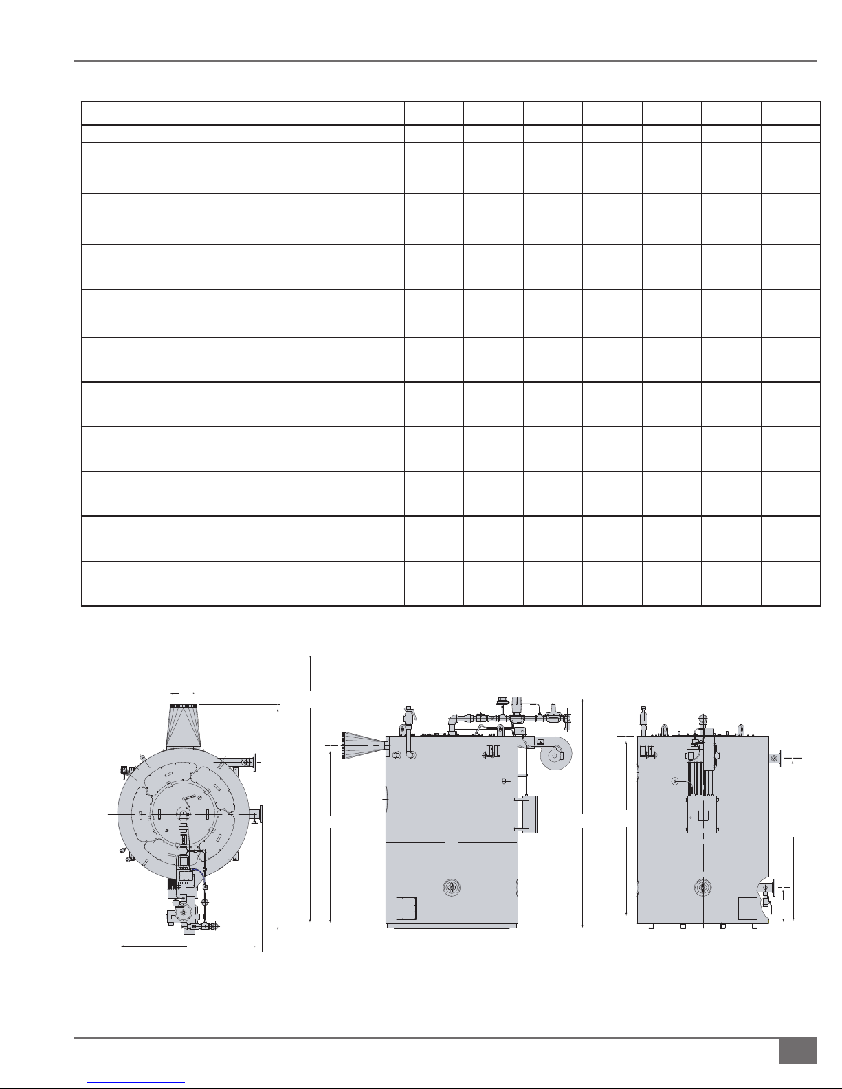
Proper placement of your Fulton Product (see Figure 1, and Tables 1 and 2) is
essential. Attention paid to the following points will save a great deal of di culty
in the future. Correct placement is the rst step to trouble-free installation,
operation and maintenance.
Adhere to the following for equipment placement and rigging:
1. Consult authorities with jurisdiction over any national or local codes
(including but not limited to National Fire Protection Agency (NFPA),
American National Standards Institute (ANSI), Underwriters Laboratories
(UL), SCA, and ASME, which might be applicable to boiler applications
before beginning.
2. Make appropriate determinations for placement, based on the following:
§ Check building speci cations and Table 2 for unit weights.
§ Ensure the equipment is to be placed on a non-combustible level base
with adequate clearances from combustible materials. See Clearances &
Serviceability section.
§ Locate boiler as close as possible to the place where the heat will be used
in order to keep pipe work costs to a minimum.
§ Ensure that there is adequate clearance around the unit to provide
access for operators and maintenance personnel to all parts of the
equipment. Ensure also that clearance provides for component removal for
maintenance. See Clearances & Serviceability section. The equipment
should be placed in a suitable boiler house or well ventilated separate
room through which personnel do not normally pass. The layout should
eliminate tra c in potentially hazardous areas. For instance, the service
engineer or the operator should not have to pass exposed, hot pipe work
to make adjustments to the boiler controls.
§ Ensure the equipment is to be placed in such a way that the electrical
components are protected from exposure to water or excessive humidity.
§ Ensure the boiler is located a safe distance from the fuel oil tank (if
applicable).
3. Determine rigging procedure, based on the following:
§ Units are shipped and crated for forklift transport. Once uncrated, all units
can be transported with a forklift and/or lifting lugs at the top of the boiler.
All skidded units can be moved with forklifts.
4 CAUTION
Do not allow weight to bear on
equipment components to prevent
damage.
2-2
§ If means of lifting are not available, place rollers beneath the frame of the
equipment for guidance to the position of where it is to be installed.
§ Under no circumstances allow weight to bear on the jacket, control panel,
burner, fuel train or fan housing of any Fulton boiler.
§ Tagged support legs on boiler are for shipping purposes only. These must be
removed at time of installation, and may not be used to mount or anchor
boilers.
© The Fulton Companies 2012
Page 9
SECTION 2 VMPW-IOM-2012-1001 INSTALLATION
F
E
C
G
K
D
B
J
A
H
H.H.
TABLE 1 DIMENSIONS REFER TO FIGURE 1
Model VMP-W 40 50 60 80 100 130 150
Unit Size BHP 40 50 60 80 100 130 150
A. Boiler Diameter
IN
MM
(B) Boiler Height
IN
MM
(C) Boiler Depth
IN
MM
(D) Boiler Height With Trim
IN
MM
(E) Overall Boiler Width
IN
MM
(F) Flue Outlet Diameter
IN
MM
(G) To Center of Flue Outlet
IN
MM
(H) Return Water Inlet Height
IN
MM
(J) Water Outlet
IN
MM
(K) Min. Clearance to Ceiling for Burner Removal
IN
MM
49
1245
84
2133
90
2286
107
2718
56
1422
12
305
79
2006
20.3
516
73.8
1870
123
3124
55
1397
91
2312
100
2540
113
2870
62
1575
12
305
83
2108
20.3
516
77.8
1980
135
3429
55
1397
97
2464
100
2540
119
3023
62
1575
12
305
89
2261
20.3
516
83.8
2130
144
3658
63
1600
100
2540
114
2896
125
3175
68
1727
14
356
95
2413
20.3
516
89.8
2280
147
3734
69
1753
100
2540
119
3022
125
3175
74
1880
14
356
95
2413
20.3
516
89.8
2280
147
3734
76.5
1943
115
2921
128
3251
149
3785
84.5
2146
14
356
107
2718
23.6
599
101.1
2570
155
3937
76.5
1943
115
2921
130
3302
149
3785
84.5
2146
14
356
107
2718
23.6
599
101.1
2570
155
3937
All data is approximate. Fulton reserves the right to change data without prior notice.
FIGURE 1 MODEL VMPW DIMENSIONS/SPECIFICATIONS REFER TO TABLES 1 AND 2
Questions? Call (315) 298-5121, or visit us online at www.fulton.com
2-3
Page 10

INSTALLATION VMPW-IOM-2012-1001 SECTION 2
! WARNING
All information in this manual is for
reference and guidance purposes,
and does not substitute for required
professional training, conduct, and strict
adherence to applicable jurisdictional/
professional codes and regulations.
Failure to provide required and safe
access to the equipment could impede
commissioning and maintenance.
Service technicians are instructed not to
commence commissioning if hazardous
conditions exist.
Failure to provide proper minimum
clearances between equipment and
combustible materials may result in re.
The installation of an exhaust fan in the
boiler room is not recommended. An
exhaust fan or similar equipment can
create a downdraft in the stack or restrict
the burner’s air supply and result in poor
combustion. It is essential only fresh
air be allowed to enter the combustion
air system. Foreign substances such as
combustible volatiles and lint may create
hazardous conditions.
NOTE: ´ When calculating ventilation requirements, heat losses from the Fulton
equipment (and other equipment) should be considered.
Clearances & Serviceability
Adhere to the following for equipment clearances and serviceability:
1. Ensure appropriate front, back, sides and top clearances are met. This
will allow access around the equipment to facilitate maintenance and a
safe work environment, and ensure technicians will commission the unit.
Technicians will not commence commissioning if hazardous conditions
exist.
2. Place boiler with clearances to unprotected combustible materials,
including plaster or combustible supports, not less than the following:
§ Heater Front: 36 in. (914 mm)
§ Heater Sides and Rear: 18 in. (457 mm)
§ Heater top: 24 in. (610 mm)
§ Allow for additional minimum clearances for personnel access and burner
removal, as necessary.
§ Verify that all clearances are acceptable with the local ordinances.
Environment, Ventilation and Combustion Air
Requirements
Ensure all labels on the boiler are legible.
All connections and safety devices, both
mechanical and electrical, must be kept
clean, with ease of access for inspection,
use and maintenance.
It is critical to provide free access of air to the boiler. To burn fuel properly, it
requires one square inch opening for every 3,000 BTU input of fuel (6.4 cm2 for
every 756 kCal).
Adhere to the following to meet ventilation and combustion air requirements:
1. Install two fresh air openings, one at a low level, 24” (610 mm) from the
oor, and one at a higher level on the equipment room wall. This will
provide a ow of air to exhaust the hot air from the equipment room.
2. Ensure the equipment room air supply openings are kept clear at all times.
2-4
© The Fulton Companies 2012
Page 11

SECTION 2 VMPW-IOM-2012-1001 INSTALLATION
TABLE 2 SPECIFICATIONS REFER TO FIGURE 1
Model VMP-W 40 50 60 80 100 130 150
Boiler Connec ons
Safety Valve Outlet
IN
MM
Safety Valve Inlet
IN
MM
Natural Gas Connec on
IN
MM
Water Supply & Return Connec ons*
IN
MM
Ra ngs (sea level to 3000 /914 m) Output
1000 BTU/HR
1000 KCAL/HR
Water Content
GAL
Liters
Light Oil Connec on
IN
MM
Burner Motor
HP
Wa! s
Approximate Weights
Shipping Weight
LB
KG
Opera ng Weight
LB
KG
Approximate Fuel Consump on at Rated Capacity+
Natural Gas
3
FT
3
M
LP Gas
3
FT
3
M
Light Oil
GPH
LPH
Min. Gas Pressure Required; In. W.C. 7 7 7 9 9 40 40
Max Gas Pressure Required (Standard Gas Train) In. W.C. 13 13 13 27 27 10 psig 10 psig
Electric Power Requirements/Amps for Burner Motor
208V 50/60 CY 3 Phase (Gas/Oil) 6.6/7.5 6.6/7.5 6.6/7.5 10.6 10.6 30.8 30.8
230V 50/60 CY 3 Phase (Gas/Oil) 6.0/6.8 6.0/6.8 6.0/6.8 9.6 9.6 28 28
460V 50/60 CY 3 Phase (Gas/Oil) 3.0/3.4 3.0/3.4 3.0/3.4 4.8 4.8 14 14
1.5
38.1
1.25
31.8
1.5
38
4
102
1356
342
210
795
Model VMP-W STANDARD MOTOR
.25
6
1.5
1119
5775
2620
7526
3414
1595
45
638
18
11
41.6
1.5
38.1
1.25
31.8
1.5
38
4
102
1693
427
290
1098
.25
6
1.5
1119
6575
2980
8994
4080
1992
56
797
23
14
53
1.5
38.1
1.25
31.8
2
51
4
102
2033
512
315
1192
.25
6
1.5
1119
7370
3340
9997
4535
2392
68
957
27
17
64.3
2
50.8
1.5
38.1
2
51
4
102
2710
683
440
1665
.25
6
3
2237
8000
3636
11670
5294
3188
90
1275
36
23
87
2
50.8
1.5
38.1
2
51
4
102
3387
853
602
2278
.25
6
3
2237
9500
4318
14520
6587
3985
113
1594
45
28
106
2
50.8
1.5
38.1
2.5
63
4
102
4405
1110
920
3482
.375
9.5
10
7460
12,350
5601
20023
9083
5182
147
2080
59
37
140
2
50.8
1.5
38.1
2.5
63
4
102
5081
1280
920
3482
.375
9.5
10
7460
12,500
5675
20172
9150
5978
169
2381
68
42
159
* 150 pound fl anged.
Questions? Call (315) 298-5121, or visit us online at www.fulton.com
CONTINUED ON NEXT PAGE
2-5
Page 12

INSTALLATION VMPW-IOM-2012-1001 SECTION 2
Model VMP-W Low Emissions (LE) MOTOR
Model VMP-WModel 40 50 60 80 100 130 150
Model VMP-W 40 50 60 80 100 130 150
Burner Motor **
HP
Wa! s
Approximate Weights
Shipping Weight
LB
KG
Opera" ng Weight
LB
KG
Approximate Fuel Consump! on at Rated Capacity+
Natural Gas
3
FT
3
M
Required Gas Pressure (IN. W.C./PSIG)
Minimum/Maximum 30/10 30/10 40/10 40/10 40/10 60/10 60/10
208V, 60 CY, 3 Phase 16.7 16.7 16.7 16.7 24.2 Consult Factory
230V 60 CY 3 Phase 15.2 15.2 15.2 15.2 22 Consult Factory
460V 60 CY 3 Phase 7.6 7.6 7.6 7.6 11 Consult Factory
Specifi ca" ons and dimensions are approximate. We reserve the right to change data without prior no" fi ca" on.
Design condi" ons based on 160 F return and 180 F supply.
+ Consump" on based on natural gas 1000 Btu/$ 3.
** Sub 20 ppm; for lower requirements, consult factory.
5
3730
6575
2982
8659
3928
1595
45
5
3730
7373
3345
9684
4393
1992
56
5
3730
8170
3706
10671
4840
2392
68
5
3730
8800
3992
12051
5466
3188
90
5
3730
10300
4672
14700
6668
3985
113
Consult
Factory
12800
5806
20585
9337
5182
147
Consult
Factory
12800
5806
20585
9337
5978
169
3. See Table 3 for minimum make up air openings required
for each model.
TABLE 3 MINIMUM MAKE UP AIR OPENING REQUIREMENTS
Model Fresh Air Opening FT2 (M2)
40 1 (.09)
50 1 (.09)
60 1.5 (.14)
80 4 (.37)
100 4 (.37)
130 5 (.46)
150 7.5 (.69)
4. If positive forced ventilation is adopted, ensure that
there will be no appreciable pressure variation in the
equipment room.
5. Avoid ventilation which creates a negative pressure
in the building as it will seriously a ect combustion
and proper operation of the burner. Please note that
exhaust fans or similar equipment can create a down
draft in the chimney or starve the burner’s air supply.
Either case may result in poor combustion or nuisance
failures. A properly designed make-up air system in the
equipment room will preclude these possibilities and is
required to maintain proper combustion.
6. Eliminate potential for high risk situations for particulate
matter to be in the combustion air supply (e.g., as a
result of construction and maintenance activities).
Utilities
¡ The Gas Supply
Adhere to the following for gas supply installation:
1. Install gas piping in accordance with all applicable
codes.
2. Ensure pipe and ttings used are new and free of dirt or
other deposits.
3. Ensure piping is of the proper size for adequate gas
supply to the gas head assembly. Consult your gas
company for speci c recommendations.
4. When making gas piping joints, use a sealing
compound resistant to the action of lique ed
petroleum gases. Do not use Te on tape on gas line
heads.
2-6
© The Fulton Companies 2012
Page 13

SECTION 2 VMPW-IOM-2012-1001 INSTALLATION
5. Ensure no piping stresses are transmitted to the equipment. The
equipment shall not be used as a pipe anchor.
6. Ensure all vent connections on diaphragms, gas valves, pressure
regulators, and pressure switches (gas- red units) are vented per local
code.
7. On gas- red units with NFPA 85 valve trains, ensure the vent valve is
piped to atmosphere per local code.
8. During any pressure testing of the system at pressures in excess of 1/2
psig (14 inch W.C.), isolate the boiler with the manual shuto valve
(located at the end of the supplied gas train) from the gas supply
piping system.
9. Ensure the supply pressure is regulated by a non-stacking, tight, shuto regulator.
10. Arrange gas piping so that it does not interfere with any cover or
burner, inhibit service or maintenance, or prevent access between
unit and walls or another unit.
11. After gas piping is completed and before wiring installation is started,
carefully check all piping connections, (factory and eld), for gas
leaks. Use an appropriate leak test solution.
¡ The Oil Supply
! WARNING
A quali ed installer, service agency or the
gas supplier must perform installation and
service on the fuel delivery system.
Do not use matches, candles, ame or
other sources of ignition to check for gas
leaks.
What to do if you smell gas:
Do not try to light the appliance.
Do not touch any electrical switch.
Do not use any phone in the building.
Leave building and contact gas supplier
from neighbor’s phone. If you cannot
reach gas supplier, phone the re
department.
When making gas piping joints, maintain
proper ventilation to reduce breathing
hazards.
An exhaust fan may draw products of
combustion into the work environment
creating a possible hazard to personnel.
Adhere to the following for installation:
1. Fuel pipes must be of approved materials and of a diameter suitable
for the quantity of oil being delivered to the burner. Vacuum must
not exceed 10 in. (254 mm) of mercury at the pump inlet. Maximum
inlet pressure to oil pump is 3 PSIG.
2. Make fuel connection in accordance with the details on the enclosed
fuel pump cut sheet.
3. Ensure fuel oil piping is in accordance with local/national
requirements.
4. Meet the maximum pressure allowed at the fuel oil pump inlet per
the National Fire Protection Association (NFPA).
5. Oil pumps are of a two-line design system, requiring a return line and
a supply line. The oil pump is factory set per Test Fire Sheet. Do not
alter the setting without consulting the factory.
6. A stop valve, a check valve, and an oil lter must be installed on the
oil supply line.
7. Ensure there are no loose ttings. Loose ttings in the fuel oil line will
permit air to enter the fuel line and cause improper ring.
4 CAUTION
It is essential that only fresh air be allowed
to enter the combustion air system. Foreign
substances, such as combustible volatiles
and lint in the combustion system can create
hazardous conditions. If foreign substances
can enter the air stream, the combustion air
inlet must be piped to an outside location.
Failure to do so will void the warranty.
To avoid failures due to poor combustion,
ensure make-up air system is properly
designed.
Questions? Call (315) 298-5121, or visit us online at www.fulton.com
2-7
Page 14

INSTALLATION VMPW-IOM-2012-1001 SECTION 2
! WARNING
All information in this manual is for
reference and guidance purposes,
and does not substitute for required
professional training, conduct, and strict
adherence to applicable jurisdictional/
professional codes and regulations.
4 CAUTION
Loose ttings in the fuel oil line will permit
air to enter the fuel line and cause improper
ring.
Electrical Supply
Adhere to the following for electrical supply installation:
1. Locate electrical schematic diagram, a copy of which is inside of the panel
box.
2. Ensure the information on the electrical drawing corresponds to your
voltage and frequency. Check the supply voltage and make sure that there
is no over- or under-voltage exceeding 10% of the nominal value.
3. Install a separate fuse switch for the contactor and a separate fuse switch
for the circulating pump. If pump motor is 3/4 HP or larger, install an
across-the-line starting switch ahead of the circulating pump motor.
4. Install wiring and ground in equipment in accordance with authority
having jurisdiction or in absence of such requirements the National
Electrical Code, ANSI/NFPA.
5. Provide a fused disconnect sized for the unit. Size fuses according to motor
name plates and local electrical codes.
6. Connect power to the terminal strip as supplied on the inside of the panel
box.
Water Supply
¡ Install Water Piping
All water supplies contain some solids, dissolved gases or dissolved minerals.
These may cause corrosion, deposition and/or fouling of equipment. To prevent
these contaminants from impacting boiler performance, valve operation and
general pipe longevity, each location must be analyzed and treated accordingly.
Adhere to the following for water piping installation:
1. Isolation valves and unions are recommended on both water connections
for ease of service.
2. Install piping so that the boiler is not supporting any additional piping.
3. Install manual purging valves in all loops and zones. Install a pressure-
reducing (automatic ll) valve in the cold water ll line to the boiler system.
Check that the proposed operation of zone valves, zone circulator(s) and
diverting valves will not isolate air separator(s) and/ or expansion tank(s)
from the boiler. Clearance from hot water pipes to combustibles must be at
least 6 inches (152 mm).
4. Pipe the water supply line to the lower opening on the back of the boiler.
Water stop valve should be in line between the boiler and the rst piece
of equipment. Hot water outlet should be piped to process/equipment
requiring hot water. Water makeup supply should be installed. Hot water
inlet should be piped to the make-up water supply.
2-8
© The Fulton Companies 2012
Page 15

SECTION 2 VMPW-IOM-2012-1001 INSTALLATION
5. Pipe the water safety valve carry piping from the outlet of the valve to a
safe blow-o point.
NOTE: ´ Do not alter water temperature/pressure gauge assembly in any way.
6. Drain valve is connected to the lowest opening at bottom rear of boiler.
Carry piping from the outlet of the valve to safe drain point. Provision
should be made for easy access to drain valve of boiler.
NOTE: ´ The water connection on the top of the boiler is the outlet connection. The
water connection on the rear of the boiler is the inlet connection.
7. Install ltration to remove particulates if appropriate.
8. Install bypass chemical feeder for corrosion inhibitor maintenance if
appropriate.
9. Install corrosion coupon holder to assess corrosion inhibitor performance if
appropriate.
NOTE: ´ The boiler is provided with a drain valve connection and a drain valve.
10. Heating system:
! WARNING
All information in this manual is for
reference and guidance purposes,
and does not substitute for required
professional training, conduct, and strict
adherence to applicable jurisdictional/
professional codes and regulations.
» An automatic pressure activated water make up valve with back
ow preventer. It must be set to maintain required Net Positive
Suction Head (NPSH) for re-circulating pumps, a positive system
pressure at the highest point of at least 5-10 PSIG, and make up
water valve should be designed to add water to the system at the
outlet of the boiler and should not be fed directly into the boiler.
» Air removal equipment, including an air separator and automatic
breather valves, along with a functioning expansion tank . Each
must be designed to system speci cations.
11. When used in conjunction with a refrigeration system, install the boiler
so that the chilled medium is piped in parallel with the boiler with
appropriate valves to prevent the chilled medium from entering the
boiler. If the boilers are connected to heating coils (located in air handling
units where they may be exposed to refrigerated air circulation) such
boiler piping systems must be equipped with ow control valves or other
automatic means to prevent gravity circulation of the boiler water during
the cooling cycle.
Water Chemistry Requirements
System water chemistry requirements are as follows:
§ pH: Range of 8.5 - 10.5
§ Oxygen: Less than 250 ppb (operating condition)
§ Total Iron/Copper: Less than 5 ppm
Questions? Call (315) 298-5121, or visit us online at www.fulton.com
2-9
Page 16

INSTALLATION VMPW-IOM-2012-1001 SECTION 2
! WARNING
All information in this manual is for
reference and guidance purposes,
and does not substitute for required
professional training, conduct, and strict
adherence to applicable jurisdictional/
professional codes and regulations.
4 CAUTION
A large amount of improperly treated makeup water can cause premature failure of the
heat exchanger resulting from scale build
up. Scale build up will reduce the e ciency
and useful life of the boiler and is not
covered under warranty.
§ Corrosion Inhibitor: Capable of maintaining iron corrosion rates <2
mpy. Due to changing environmental restrictions a non-heavy metal
ALL ORGANIC inhibitor is recommended which is designed for multi
metal systems including ferrous metals and yellow metals such as
copper and brass.
§ Chloride: Less than 250 ppm
Adhere to the following:
1. Refer to your water conditioning or chemical treatment supplier for
analysis and recommendations for proper system conditions.
2. Follow a program with appropriate monitoring and maintenance of
system water conditions as provided by your water conditioning or
chemical treatment supplier.
3. Operate the boiler in a closed-loop system using water or water/glycol
(not requiring a make-up water supply). A large amount of improperly
treated make-up water can cause premature failure of the heat
exchanger resulting from scale build up. Scale build up will reduce the
e ciency and useful life of the boiler and is not covered under warranty.
¡ Prevent Oxygen Contamination
There are several ways to prevent boiler water oxygen contamination:
§ Minimize system leaks to minimize make up water requirement
§ Do not use open tanks or ttings
§ Do not use oxygen permeable materials anywhere in the water
system
§ Repair leaks in the system quickly
§ Eliminate ttings wherever possible
§ Use air elimination devices in system piping
¡ Eliminate System Air
NOTE: ´ There are no built-in boiler air eliminating features.
Adhere to the following for air elimination:
1. The installation of an air separator and air eliminator (air vent) is required.
2. To prevent scale corrosion in boiler and associated piping, make up
water must be kept to a minimum. This is best achieved by ensuring
immediate repair of all leaks and that system pressure is maintained.
2-10
3. If a sealed diaphragm-type expansion tank is used, install an air
eliminator in the hot water piping at the air separator.
4. If an air cushion type expansion tank is used, pipe tank directly into
© The Fulton Companies 2012
Page 17

SECTION 2 VMPW-IOM-2012-1001 INSTALLATION
boiler supply.
5. On multi-zoned systems (or a system with both space and domestic water
heating), air elimination must be provided either in the common piping or
on every loop.
6. When the boiler is installed at a higher level than baseboard radiation (if
used), air elimination must be provided directly above the unit.
Piping Specifi cations
For piping, the basic considerations are: the design temperature, the pressure
retained by the pipe, the uid in the pipe, the load resulting from thermal
expansion or contraction, impact or shock loads imparted such as water hammer,
external loads, wind loads and vibration from equipment.
Adhere to the following for piping installation:
1. Ensure the arrangement of the piping and its appurtenances takes into
consideration the location of other structures and equipment adjacent to
the piping, which may result in freezing interference and/or damage as a
result of expansion, contraction, vibration, or other movements.
2. Consider the appropriate location and orientation of valves necessary
for safe operation and isolation of the piping. Valves are used in piping
systems to stop and start the ow of uids, to regulate ow, to prevent the
back ow, and to relieve excessive pressure build up in the piping.
! WARNING
All information in this manual is for
reference and guidance purposes,
and does not substitute for required
professional training, conduct, and strict
adherence to applicable jurisdictional/
professional codes and regulations.
The vent line connection on the gas
pressure regulator must be piped to
outdoor air by the installer in accordance
with National Fuel Gas Code, ANSI Z2231-1991 or latest addenda. In Canada, gas
installations must be in accordance with
the current CAN/CGA B149.1 and 2 and/or
local codes.
4 CAUTION
Some soap used for leak testing is
corrosive to certain types of metals. Use
an appropriate leak test solution. Clean all
piping thoroughly after completing the leak
check.
3. Ensure all piping and piping components are suitable for the design
temperatures, pressure and uid used in the system.
4. Ensure all pipework is constructed from seamless mild steel pipe, Schedule
40 or Schedule 80 as required by code and/or application; or copper if
system parameters allow.
5. During construction of the installation, ensure that no dirt, water, or
residue from welding is left in the system.
6. Provide expansion joints or properly designed and sited loops to
accommodate thermal expansion. Thermal expansion should be calculated
using the maximum possible utilization uid temperature, regardless of
whether the pipe considered is in the feed or return circuit. Steel pipe will
expand approximately 1 “ per 100’ over a 100° F temperature rise (1 mm
per meter over 100 C rise).
7. Provide supports and anchors for all pipes where necessary to prevent
undue stresses from being placed on items of equipment, including
pumps, valves, and the boiler. Supports and anchors which will not
interfere with thermal expansion should be chosen.
8. Cut screw threads carefully and accurately. If possible, new tools should be
used. It is recommended that GR5 or higher tensile steel bolts be used for
all anged joints.
9. Use gaskets to make all anged connections. Gasketing material must be
Questions? Call (315) 298-5121, or visit us online at www.fulton.com
2-11
Page 18

INSTALLATION VMPW-IOM-2012-1001 SECTION 2
! WARNING
All information in this manual is for
reference and guidance purposes,
and does not substitute for required
professional training, conduct,
and strict adherence to applicable
jurisdictional/professional codes and
regulations.
Hot pipework and vessels must be
adequately insulated with material
suited to the temperature and
application to prevent both heat loss
and personnel injury.
suitable for use with the pressure, temperatures and uids in the system.
Ensure that all bolts are tightened evenly and to the torque recommended
values provided by the gasket manufacturer.
10. Install high point bleeds at all high points in the system piping. 1/2” x 12”
nipples welded in the top of the piping with ball valves and plugs attached
are to be used.
11. Install all pipes with a pitch to facilitate draining and venting.
Insulation
After the appropriate system tests have been satisfactorily completed (see
Testing section of this manual), all hot pipework and vessels must be adequately
insulated with material suited to the temperature and application to prevent
both heat loss and personnel injury. For inspection and maintenance purposes,
leave pumps, anges, valves and ttings uninsulated but suitably shielded for
safety. Removable insulation may also be used over these components.
System Interfaces
Proper selection and installation of the components in the system will ensure
proper and safe operation of the boiler. Consult Fulton representative or contact
Fulton at (315) 298-5121.
¡ Fill Connection
The system is usually lled from the lowest point, with the aid of a pump. On skidmounted units, a ll connection is provided in the inlet piping to the pump.
Pressure Gauges
The range in which readings are expected to fall should comprise mid-scale
on the pressure gauge chosen. Pressure gauges must be able to withstand
overpressure equal to the rating of the safety relief valves, normally 100 psig.
NOTE: ´ The Water temperature pressure gauge should not be altered in any way.
Assembly of Multi-Skid Systems
Adhere to the following for multi-skid engineered systems:
1. Refer to the Fulton mechanical/electrical drawings during assembly.
2. Ensure that equipment orientation allows for operation interface and
maintenance.
3. Align the skids as shown on the drawings ensuring that skid fasteners (skid
joint angles) are matched. The skid joint angles are a matched set and the
edges of the fasteners should be exactly aligned.
2-12
© The Fulton Companies 2012
Page 19

SECTION 2 VMPW-IOM-2012-1001 INSTALLATION
NOTE: ´ Do not bolt the skids to the housekeeping pad/ oor until all of the piping
has been reassembled and tightened.
4. Ensure the skids are level and at before fastening the skids together with
the supplied bolts. The skids should be leveled front to back, side to side
and corner to corner. Failure to properly level the skids will result in piping
misalignment. A level or laser level should be used to verify skid alignment
(when a standard level is used, the length should be appropriate for the
skid). If assembling multi-component support stands, attach sections
using the supplied bolts through the tank frame mounting plates. These
should be hand tight until all of the piping is assembled. Note: skids are
leveled at the factory using a laser level.
5. Connect the piping between the skids by matching the union connections
and/or ange stamps and tightening. Refer to the mechanical drawing
as necessary to con rm location of spool pieces etc. as the ange stamps
are shown on the drawing in hexagonal callouts. The ange stamps
should matched and aligned (the ange stamps should be directly across
from one another. Rotating a ange will result in piping misalignment).
Bolts should be hand tight until all of the piping is assembled. Refer to
the appropriate instructions to tighten the anges to the required torque
speci cations. Support pipe runs as required.
! WARNING
All information in this manual is for
reference and guidance purposes,
and does not substitute for required
professional training, conduct,
and strict adherence to applicable
jurisdictional/professional codes and
regulations.
Assure all electrical connections are
powered down prior to attempting
replacement or service of electrical
components or connections of the
equipment.
Cements for plastic pipe should
be kept away from all sources of
ignition. Proper ventilation should
be maintained to reduce the hazard
and to minimize breathing of cement
vapors.
6. Ensure that a low point drain is installed in the piping.
7. Connect the conduit runs between the skids and tighten conduit
connectors.
8. Locate the supplied wiring for the equipment and pull wiring through
the appropriate conduit runs. Electrical wires are labeled for easy landing.
Connect all wiring per the Fulton supplied electrical drawings.
9. If a header is supplied, mount the header as shown in the mechanical
drawing.
NOTE: ´ For piping supplied in sections, make up and connect hand tight until all
sections are in place to ensure sections align properly. Sections are match marked
for reassembly.
10. Tighten all connections.
11. Pneumatically test the piping (at 15 psig maximum) prior to lling the
systems.
12. Check bolts and connections for tightness after the rst heat up cycle.
Retorquing may be required.
No shuto of any kind may be
placed between the safety relief
valve and the equipment, or in the
discharge pipe between such valve
and the atmosphere. Doing so may
cause accidental explosion from
overpressure.
Discharge from safety relief valve
must be con gured so that there
is no danger of scalding personnel
or causing equipment damage.
Provisions must be made to properly
drain safety relief valve discharge
piping.
For reasons of safety, the hot exhaust
gas duct and chimney must be
insulated or shielded within the
locality of the heater in compliance
with local codes and regulations.
Stack and Flue
An appropriately sized stack should be connected to the ue gas outlet at the
boiler. The proper ue size and draft control is most important for proper burner
operation. See Table 4.
Stack and chimney must be constructed from material that is rated for 1000 F
Questions? Call (315) 298-5121, or visit us online at www.fulton.com
4 CAUTION
The stack arrangement and draft
conditions should be in accordance
with the information in this manual for
proper performance of the equipment.
2-13
Page 20
INSTALLATION VMPW-IOM-2012-1001 SECTION 2
! WARNING
All information in this manual is for
reference and guidance purposes,
and does not substitute for required
professional training, conduct,
and strict adherence to applicable
jurisdictional/professional codes and
regulations.
Non-Fulton product information is for
reference purposes only. No Fulton
document may substitute for full
review of documentation available
from the component manufacturer.
4 CAUTION
Boilers damaged due to adverse water
conditions are not covered by warranty.
The weight of all piping must be
properly supported. Failure to support
piping may result in equipment
damage and/or system leakage.
Piping must take into consideration
potential for freezing interference and/
or damage as a result of expansion,
contraction, vibration, or other
movements.
Dirt, water, and/or other debris in the
piping system after welding may result
in equipment failure.
To maintain a reasonable
temperature in the equipment area
and ensure safety to personnel, the
section of the chimney duct within
the building should be insulated.
operating temperature. Check all local codes for requirements.
The ue must be as large or larger than the outlet on the vessel. Avoid ue
piping and elbows by placing the equipment as close as possible to the chimney.
TABLE 4 MINIMUM FLUE SIZES
Model Minimum Flue Size
inches (mm)
40 12 (305)
50 12 (305)
60 12 (305)
80 14 (356)
100 14 (356)
130 14 (356)
150 16 (406)
Adhere to the following for stack and ue installation (see Figure 2):
1. Ensure the stack rises continuously to the connection at the chimney and
contains no more than two bends at 45 degree angles or less. If required,
as a result of space limitations, one 90 degree elbow (or tee) can be tted
at the back of the vessel.
2. Ensure 2 feet (0.6 m) of straight, horizontal ue before any change in
direction, tting or draft regulator. This is to prevent potential pilot or
main ame failures due to back pressure build up during ignition. Any
alternative stack arrangement must supply negative 0.02 to 0.04”wc.
3. Ensure the run in the total distance of stack ducting, as measured in a
straight line from the outlet of the boiler to the outlet of the stack, does
not exceed 25% of the rise. With the exception of the duct run previously
described, horizontal sections of ducting must be avoided and should not
exceed 4 feet (1.2 m) total. See Figure 2.
4. Ensure the stack, chimney, and any components associated with the stack,
such as heat reclaimers or assist fans, are constructed from material that is
rated for a 1000 F (538 C) operating temperature.
5. Ensure the stack and chimney material complies with all applicable codes.
6. Make adequate provisions for the support of the weight of the chimney
and stack to avoid having a load imparted to the outlet connection of the
equipment.
2-14
7. Ensure the draft, when ring, is negative and constant. A reading of -0.02
to -0.04”wc (-0.508 to -1.016 mm) when the unit and stack are cold usually
indicates su cient draft. When the unit is running and the stack is hot, the
draft should read -0.04 to -0.08 “wc (-1.016 to -1.524 mm) negative.
8. The installation of a draft regulator by the client/contractor is
recommended at all installations. This will help to maintain the required
draft. The placement of the draft regulator should be as shown in Figure 3.
Insulate the section of the chimney duct within the building.
© The Fulton Companies 2012
Page 21

SECTION 2 VMPW-IOM-2012-1001 INSTALLATION
Roof
Minimum
6' Above
Any Structure
Within 30'
Support As
Necessary
Install
Appropriate
Weather
Cap
Horizontal
Run 2'
Draft Regulator
(If Necessary)
Draft Regulator
(If Necessary)
Expansion Joints
As Required
Horizontal
Run 2'
60¡
(45¡ Min.)
Cleanout
Door
Cleanout
Door
Cleanout
Door
This Distance
Must Not
Exceed 70%
Of Total Rise
Baffle
3'
3'
30¡
Max
Stagger
Entrances
A A
A-A
Total
Rise
9. Concentration levels of only a few ppm of chlorine
containing compounds in combustion air can produce
serious corrosion of the ue over long periods of time.
High chlorine containing compounds such as carbon
tetrachloride or perchloroethylene would be prime
suspects.
¡ Exhaust Side Wall Venting
Boilers for which sidewall venting (Figure 4) may be utilized
are propane, natural gas, or combination propane and natural
Questions? Call (315) 298-5121, or visit us online at www.fulton.com
FIGURE 2 TYPICAL STACK ARRANGEMENT
gas sizes 10 to 30 HP.
Adhere to the following for installations requiring sidewall
venting:
1. Flue vent piping must be pitched upward at ¼ in (6.35
mm) per one foot (3.048 m) of length.
2. An UL-approved draft fan must be installed to provide
su cient draft (-0.02 to -0.04” wc) to safely vent
products of combustion.
2-15
Page 22
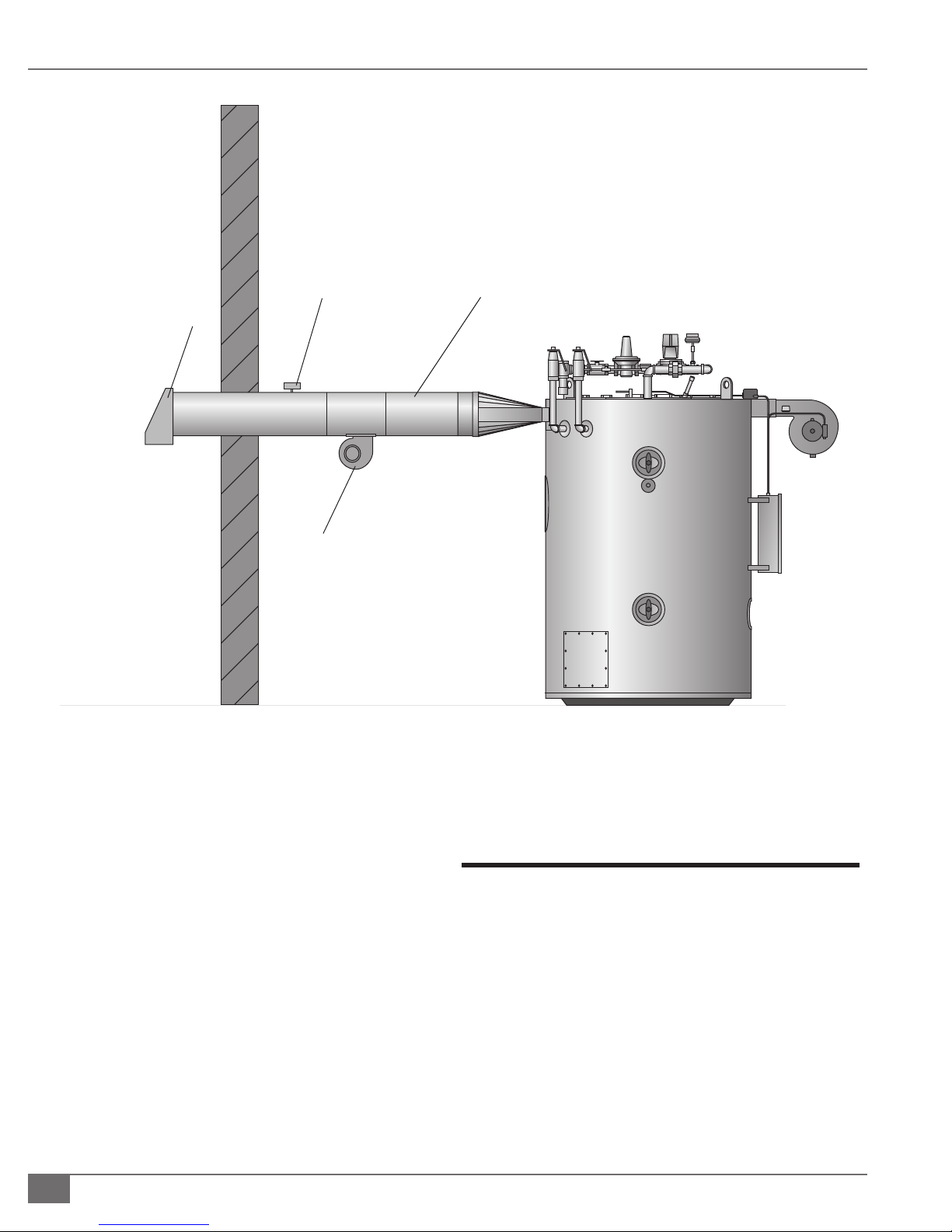
INSTALLATION VMPW-IOM-2012-1001 SECTION 2
Air Flow
Safety Switch
U.L. Approved
Induced Draft Fan
Side Wall
Vent
Termination
(By Others)
Side Wall Vent
(By Others)
FIGURE 3 TYPICAL SIDEWALL VENTING
3. The draft fan should be located as close to the ue
outlet as possible.
4. Draft regulation su cient to lower the draft to between
-0.02 to -0.04 “ wc may be required. The draft regulator
must be between the boiler and the fan.
5. The draft fan shall have an air ow proving switch wired
in series with the boiler air safety switch.
6. The sidewall vent total length from boiler exhaust to
termination shall not exceed 35 feet (10.6 m) with 4
elbows maximum.
Testing
Upon completion of the installation, perform the following
testing:
1. A pneumatic test of water piping not exceeding 15
psig.
2. Leak tests at all welds and joints to ensure that the
system is free from leaks.
2-16
© The Fulton Companies 2012
Page 23

OPERATION
INTRODUCTION
INSTALLATION
1
2
OPERATION
MAINTENANCE
WARRANTY & PARTS
3
4
5
Questions? Call (315) 298-5121, or visit us online at www.fulton.com
3-1
Page 24

OPERATION VMPW-IOM-2012-1001 SECTION 3
! WARNING
All information in this manual is for
reference and guidance purposes,
and does not substitute for required
professional training, conduct, and strict
adherence to applicable jurisdictional/
professional codes and regulations.
Do not operate, or allow others to operate,
service or repair this equipment unless
you (they) fully understand all applicable
sections of this manual and are quali ed
to operate/maintain the equipment.
Defective or improperly installed
equipment is hazardous. Do not
operate equipment which is defective or
improperly installed.
Defective equipment can injure you
or others. Do not operate equipment
which is defective or has missing parts.
Make sure all repairs or maintenance
procedures are completed before using
the equipment. Do not attempt repairs or
any other maintenance work you do not
understand.
4 CAUTION
Installation in accordance with the
guidelines within the manual should be
fully completed before performing the initial
start-up; and start-up must be complete
prior to putting the unit into service. Starting
a unit without the proper piping, venting
or electrical systems can be dangerous and
may void the product warranty.
Start-Up Preparation & Installation Review
Review the installation section of this manual carefully. Con rm accordance with
the Installation guidelines, including:
1. You have read and followed all safety information.
2. The equipment area is in conformance with established boiler room
requirements. Review national and local codes.
3. There are no obstructions left in the uid circuit from pressure leak testing
such as blanking plates in anged joints.
4. Boiler is located with the proper clearances as shown in Installation
section of this manual.
5. Relief valves have been properly piped to oor drains.
6. Flue gas from the boiler is properly vented.
7. Combustion air openings are not obstructed in any way and have
adequate capacity.
8. There are no ammable liquids, materials or hazardous fumes present in
the environment.
9. Nothing was damaged or knocked loose during shipment and installation.
Inspect the main gas train and trim assembly to be sure they were not
damaged during shipment or installation.
10. Local authorities where approval for start-up is required have been
noti ed. In some localities, nal inspection of services may be required.
11. Installation checklist is complete.
} FILL AND AIR REMOVAL PROCEDURE
1. Close combination shuto /purge valve in supply, all drain cocks, the
shuto valve for the pressure reducing ( ll) valve, and all manual air vents.
2. Open all other system shuto valves and one of the zone valves, the vent
on the combination shuto / purge valve and the shuto valve to the
pressure-reducing ( ll) valve.
“Factory Trained Personnel” refers to
someone who has attended a Fulton Service
School speci cally for the equipment
covered in this manual.
3-2
3. Water will now begin to ll the system. Air will escape through the vent
on the combination shuto / purge valve. Continue lling until a constant
stream of water (no bubbling) is discharged from the vent.
4. Close the zone valve on the purged loop, and open the zone valve on
the next loop to be purged. When all air has escaped and only water is
discharged, close the zone valve. When all zones have been purged (one at
a time), close the vent on the combination shuto /purge valve.
5. At this point, the system has been initially lled. However, air pockets
may still remain at high points in the system and in heating loops above
the level of the combination shut/o purge valve. It is quite possible,
© The Fulton Companies 2012
Page 25

SECTION 3 VMPW-IOM-2012-1001 OPERATION
depending on the particular system that all piping above the combination
shuto /purge valve still contains air. If manual vents are installed on the
system high points, these should be opened to vent these locations. When
only water is discharged from all vents, the initial purging is complete.
6. Open the combination shuto / purge valve (keep the vent closed). With
the gas shuto valve closed, turn on power to the boiler and operate the
circulator. Circulate the system water for approximately 30 minutes to
move all air to the automatic air separation point.
7. Again, open manual air vents at high points of heating loop until a
constant stream of water is discharged from the vent. Close the vent and
make sure it’s watertight. Repeat procedure for all high points and for
every zone.
8. Check temperature/pressure indicator reading, which should equal the
pressure-reducing ( ll) valve set pressure. No more water should be
entering the system. Close the shuto valve on the cold-water ll line.
9. Visually inspect all pipe joints and equipment connections for leaks. If
necessary, drain system, repair leaks and re ll/purge the system. If no
pressure drop is detected for a period of two hours under pressure, the
system may be considered watertight.
! WARNING
All information in this manual is for
reference and guidance purposes,
and does not substitute for required
professional training, conduct,
and strict adherence to applicable
jurisdictional/professional codes and
regulations.
4 CAUTION
Do not use this equipment if any part
has been under water (or subjected to
heavy rains/water if the equipment
does not have NEMA 4 wiring, controls
and instrumentation). Immediately
call a quali ed service technician to
inspect the equipment and to replace
any part of the control system and/or
gas control(s) which have been under
water.
10. When purging is completed, make sure the following are open—
combination shut-o /purge valve, shuto valve to pressure reducing ( ll
valve), shuto valve in cold water ll line, and shuto valve in return line.
11. Make sure the following are closed - all drain cocks, the vent on the
combination shuto -purge valve, & all manual vents. Reset zone valves to
normal mode of operation and turn o power to boiler.
12. Open fuel shuto valve, allowing fuel to ow to the boiler.
Start-Up Service
If start-up service has been included in the order, the factory should be contacted
after the installation has been successfully completed and approved by the
client’s representative or engineers. Where possible, contact the factory at least
three weeks before a Fulton service engineer is required on site.
Consider the following in preparation for your on-site visit:
1. All procedures covered in manual sections Start-Up Preparation and
Fill the System, including installation review, air testing of piping, pump
alignment (where applicable), and lling the system must be completed
before the service person’s arrival.
Please read these instructions and
post in an appropriate place near the
equipment. Maintain in good legible
condition.
2. Depending on the size of the system and the amount of service time
contracted, start-up service includes ring the boiler, checking, verifying
and adjusting all safety settings.
3. Careful preparation can expedite the commissioning of your boiler. Most
delays can be avoided by following the instructions in this manual. Failure
to complete required procedures properly can result in the need for further
Questions? Call (315) 298-5121, or visit us online at www.fulton.com
3-3
Page 26

OPERATION VMPW-IOM-2012-1001 SECTION 3
! WARNING
All information in this manual is for
reference and guidance purposes,
and does not substitute for required
professional training, conduct,
and strict adherence to applicable
jurisdictional/professional codes and
regulations.
Crystalline silica may be present
in components of this equipment.
Exposure to crystalline silica may
pose signi cant health hazards,
including but not limited to eye and
respiratory system damage. Per
the Centers for Disease Control and
Prevention (CDC) and Occupational
Safety and Health Administration
(OSHA), appropriate Personal
Protective Equipment must be worn
to minimize exposure to hazardous
substances. Refer to most current
guidelines o ered by the CDC and
OSHA for more information, including
Personal Protective Equipment
recommendations.
service time, at extra cost to the customer.
4. Service people will not commence start-up if there are obvious system
de ciencies. However, start-up service in no way constitutes a system
design check or approval of the installation.
5. In addition to commissioning the boiler, the service person will also
familiarize heater room personnel with the operation of all Fulton
equipment. Personnel must be quali ed to understand the basic operation
and function of controls.
Initial Start-Up
Adhere to the following:
1. Turn on the main power fuse switch.
2. Activate the boiler power ON switch, located on the side of the panel box.
NOTE: ´ The Low Water Control will also be activated when the boiler is powered
on. With the unit full of water, the Low Water Relay requires manual reset.
3. If for any reason the water leaves the unit the Low Water Control will
automatically turn the burner o , and if audible alarm is installed, alarm
will activate.
When opening any drains on the
equipment or piping system, steps
should be taken to avoid scalding/
burning of personnel due to hot
uids. Whenever possible, the system
should be cooled prior to opening any
drains.
Use only your hand to turn valve
handles. Never use tools. If the
handle will not turn by hand, don’t try
to repair. Forced or attempted repair
may result in re or explosion.
WHAT TO DO IF YOU SMELL GAS :
Do not use matches, candles, ame
or other sources of ignition to check
for gas leaks. Do not try to light the
appliance. Do not touch any electrical
switch; do not use any phone in your
building. Immediately call your gas
supplier from a neighbor’s phone.
Follow the gas supplier’s instructions.
If you cannot reach your gas supplier,
call the re department.
¡ Combustion
It is critical for all personnel to be familiar with start up, controls, and shutdown
procedures.
} STARTING THE BURNER GAS
1. Verify incoming gas pressure.
2. Open the manual gas cocks on the pilot and main lines on the gas head.
3. Switch on the main power to the burner. If the water level relay is equipped
with a manual reset. If the boiler was in a low water condition, the manual
reset button must be pressed.
4. Check motor rotation.
5. Start the burner by turning on the switch on the outside of the panel box.
The blower motor will begin to deliver air into the furnace.
6. When su cient air pressure has built up in the blower housing, the air
switch located on the top side of the blower housing will make contact
and after a seven-second delay, will allow the ignition transformer and
pilot valve to operate. This creates pilot re.
7. When the pilot ame is established, the ame rod or UV scanner senses
the electrical current (microamps). The signal is transmitted to the
protectorelay, which opens the main gas valve for full re.
3-4
© The Fulton Companies 2012
Page 27

SECTION 3 VMPW-IOM-2012-1001 OPERATION
NOTE: ´ For new installations/burner has been disassembled, the burner may not
re upon rst attempt because air must be cleared from gas lines. The burner
protectorelay may go into lockout mode; allow a period of one minute to elapse,
then repeat procedure for starting the burner.
} STARTING THE BURNER OIL
1. Open the oil line’s shut-o valves.
2. Verify oil is present at the oil pump.
3. Switch on main power to burner. If the boiler was in a low water condition,
the manual reset button must be pressed.
4. Start the burner by turning on the switch on the outside of the panel box.
The blower motor will begin to deliver air into the furnace.
5. As the blower starts, the magnetic oil valve is energized, allowing the oil
pump to deliver fuel for ignition.
6. If the protectorelay does not sense ame via the CAD cell or UV scanner
located on the top of the burner in approximately 15 seconds, it will shut
down the burner.
! WARNING
All information in this manual is for
reference and guidance purposes,
and does not substitute for required
professional training, conduct,
and strict adherence to applicable
jurisdictional/professional codes and
regulations.
Do not attempt to start the
equipment for any testing prior
to lling and purging the vessel.
A dry re will seriously damage
the equipment and may result in
property damage or personnel injury
and is not covered by warranty. In
case of a dry ring event, shut o
the fuel supply and allow the vessel
to cool to room temperature before
uid is reintroduced to the pressure
vessel.
Flame Programmers
Refer to inserts provided.
Operating Controls
¡ Water Relief Valve
The Water Relief Valve releases extra pressure.
¡ Water Outlet Valve
The Water Outlet Valve serves as the isolation valve for the system.
¡ Temperature Control
The Temperature Control is a digital indicating control used to turn the boiler on
and o , and to control the ring rate when the boiler is modulated. The digital
display will show both the boiler process temperature and the boiler setpoint.
¡ Operating Temperature Aquastat
4 CAUTION
A quali ed installer, service agency
or the gas supplier must perform
installation and service on the fuel
delivery system.
Before commissioning the equipment,
verify with authorized personnel that
the gas lines have been purged.
Never attempt to operate equipment
that has failed to pass all the safety
checks.
After checking controls by manual
adjustment, make sure they are always
reset to their proper settings. Contact
your Fulton dealer before modifying the
equipment.
The Operating Temperature Aquastat controls the working temperature of the
boiler. This is an ASME CSD-1 code control which will turn the boiler o when the
water temperature exceeds its setpoint. It is an auto-reset control.
Questions? Call (315) 298-5121, or visit us online at www.fulton.com
3-5
Page 28

OPERATION VMPW-IOM-2012-1001 SECTION 3
! WARNING
This boiler is equipped with an ignition
device which automatically lights the
burner. Do not try to light burner by hand.
Operating this equipment beyond its
design limits can damage the equipment
and can be dangerous. Do not operate the
equipment outside of its limits. Do not try
to upgrade the equipment performance
through unapproved modi cations.
Unapproved modi cations may cause
injury, equipment damage, and will void
the warranty.
Check daily that the equipment area
is free and clear of any combustible
materials, including ammable vapors
and liquids.
Do not tamper with safety features
provided by the operating controls.
Should overheating occur or the gas
supply fails to shut o , manually shut o
the gas supply external to the equipment .
¡ High Limit Aquastat/High Temperature Limit
The High Limit Aquastat/High Temperature Limit prevents over-temperature
conditions. This is an ASME CSD-1 code control which includes a manual
reset feature for over-temperature. Press the manual reset button when the
temperature drops to reset the control.
¡ Air Safety Switch
This switch is controlled by the pressure of air entering the burner. This
switch proves that the blower fan is delivering combustion air.
¡ Probe Type Low Water Cut-Off
The Low Water Cut-O shuts down the unit when the water level is too low, after
a three-second time delay to prevent nuisance shut downs. Fulton boilers are
equipped with ASME CSD-1 Code controls which include a manual reset feature
on the burner low water cut o relay. Press the low water reset button to reset
the control, and the boiler will start.
Optional Circulating Pump Switch
The fused switch that controls the circulating pump should be kept in the ON
position at all times during boiler operation and non-operating mode of the
boiler. It should be placed in the OFF position when repairs or adjustments must
be made.
4 CAUTION
Operation of the circulating pump for any
amount of time without rst bleeding will
result in equipment damage.
For all systems containing boilers or un red
steam generators, the water chemistry in
the boiler (generator) must be kept within
required limits. Failure to do so may cause
premature pressure vessel failure and poor
steam quality and will void the warranty.
If any “Manual Reset” limit device trips
DO NOT reset without determining and
correcting the cause. (Manual Reset Limits
may include: ame safeguard, high or low
gas pressure, high temperature limit, low
water).
Never tamper with low water (liquid level)
cuto sensors or circuitry.
Cycle Testing
The boiler should be cycled tested and automatically allowed to go through
its normal starting sequence several times to verify that all components are
functioning properly. This will also verify that combustion is set properly so that
boiler light o has a smooth transition from ignition to main ame.
A minimum of 10 cycles should be met without any ame failures, with
combustion readings comparable to the factory test re sheet and no interlocks
causing the boiler to shutdown.
Before Leaving the Installation
1. Check all controls to insure they are operating properly. Cycle the boiler
several times by raising and lowering operating temperature on the
thermostat.
2. Make sure the installation complies with all applicable codes.
3. Turn switch to OFF position.
3-6
© The Fulton Companies 2012
Page 29

SECTION 3 VMPW-IOM-2012-1001 OPERATION
Questions? Call (315) 298-5121, or visit us online at www.fulton.com
3-7
Page 30

OPERATION VMPW-IOM-2012-1001 SECTION 3
3-8
© The Fulton Companies 2012
Page 31

MAINTENANCE
INTRODUCTION
INSTALLATION
1
2
OPERATION
MAINTENANCE
WARRANTY & PARTS
3
4
5
Questions? Call (315) 298-5121, or visit us online at www.fulton.com
4-1
Page 32

MAINTENANCE VMPW-IOM-2012-1001 SECTION 4
! WARNING
All information in this manual is for
reference and guidance purposes,
and does not substitute for required
professional training, conduct,
and strict adherence to applicable
jurisdictional/professional codes and
regulations.
Follow all proper lockout/tagout
procedures for service.
Crystalline silica may be present
in components of this equipment.
Exposure to crystalline silica may
pose signi cant health hazards,
including but not limited to eye and
respiratory system damage. Per
the Centers for Disease Control and
Prevention (CDC) and Occupational
Safety and Health Administration
(OSHA), appropriate Personal
Protective Equipment must be worn
to minimize exposure to hazardous
substances. Refer to most current
guidelines o ered by the CDC and
OSHA for more information, including
Personal Protective Equipment
recommendations.
Before beginning any maintenance,
ensure area is free of any combustible
materials and other dangers.
Daily Maintenance Schedule
Daily maintenance and inspection must include the following:
1. Observe operating temperature and general conditions.
2. Make sure that the ow of combustion and ventilating air to the boiler is
not obstructed.
3. Ensure boiler area is free and clear of any combustible materials, including
ammable vapors and liquids.
Weekly Maintenance Schedule
Weekly maintenance and inspection must include the following:
1. Check inlet gas pressure at the beginning of the gas train.
2. Observe the conditions of the main ame. A normal high re ame shows
an orange screen with a blue halo. In Low re, the burner should display a
reddish-orange glow.
3. Correct air adjustment is essential for the e cient operation of this boiler.
If an adjustment to the combustion is necessary, the ue gas composition
should be checked with a carbon dioxide (CO2) or oxygen (O2) analyzer
to set conditions. Refer to Procedure for Primary Air Adjustment/
Inspection and Procedure for Secondary Air Adjustment/Inspection
sections of this manual.
Monthly Maintenance Schedule
The following steps should be carried out monthly:
1. Make sure main power switch is o before starting work. I
What to do if you smell gas:
Do not try to light the appliance.
Do not touch any electrical switch.
Do not use any phone in the building.
Leave building and contact gas
supplier from neighbor’s phone. If you
cannot reach gas supplier, phone the
re department.
4 CAUTION
All maintenance procedures should
be completed by trained personnel.
Appropriate training and instructions
are available from the Fulton Service
Department at (315) 298-5121 or your
local Fulton Thermal Representative.
4-2
2. Test low gas pressure switch and high gas pressure switch, if applicable.
3. Clean water pump strainers (not standard).
4. Check scanner and ignition electrodes.
5. Check starter contacts. Burned or pitted contacts should be replaced. Do
not use sand paper or le to clean.
6. View ame detection strength via the boiler control.
7. Test high-limit temperature control by reducing setting below the
operating temperature. Burner should shut o . Return high limit to
previous setting. Then press the manual reset.
8. Test operating temperature control by reducing temperature setting as
necessary to check burner operation.
© The Fulton Companies 2012
Page 33
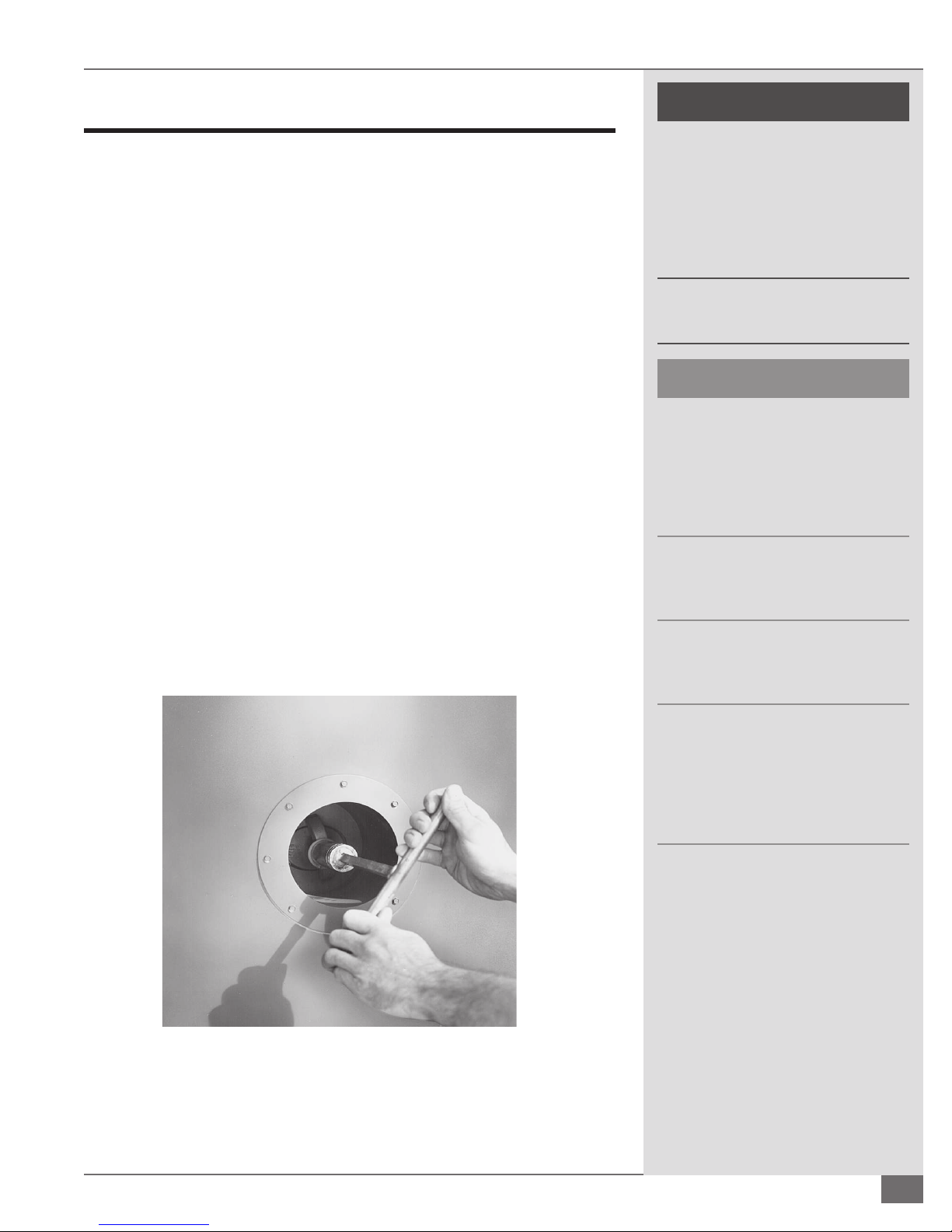
SECTION 4 VMPW-IOM-2012-1001 MAINTENANCE
Recommended Semi-Annual Maintenance Schedule
The following steps should be carried out semi-annually:
1. Clean the gas burner assembly:
» Disconnect the gas head from the burner by disconnecting the
union. Withdraw the burner assembly and clean the ignition
electrode.
» Check that the settings of the gap, if applicable, and ignition
electrode are accurate.
» Reassemble the burner assembly and check the scanner setting.
» Check the combustion e ciency of the burner and adjust if
necessary.
2. Check electrical controls and motors for correct operation.
3. Check water pump for correct operation.
4. Shut o the boiler completely and drain.
5. Replace hand hole gaskets as follows:
» Remove the hand hole assembly using a 1-1/4” tee handle
wrench or 1-1/4” 1/2” drive socket wrench. See Figure 4. Remove
the old gasket and thoroughly clean the surface on the boiler and
the plate.
! WARNING
All information in this manual is for
reference and guidance purposes,
and does not substitute for required
professional training, conduct,
and strict adherence to applicable
jurisdictional/professional codes and
regulations.
Never use open ame or other sources
of ignition to check for gas leaks.
4 CAUTION
All maintenance procedures should
be completed by trained personnel.
Appropriate training and instructions
are available from the Fulton Service
Department at (315) 298-5121 or your
local Fulton Thermal Representative.
In order to meet warranty conditions,
ensure all appropriate maintenance
activities are performed.
Use caution when using any cleaning
solutions. Refer to local regulations for
proper cleaning solution disposal.
FIGURE 4 REMOVE ASSEMBLY WITH TEE HANDLE WRENCH
If the gasket leaks while pressure is
being built up, tighten only enough to
stop leakage. Never tighten more than
necessary to prevent leakage. Excessive
tightening may shorten the life of the
gasket.
Questions? Call (315) 298-5121, or visit us online at www.fulton.com
4-3
Page 34
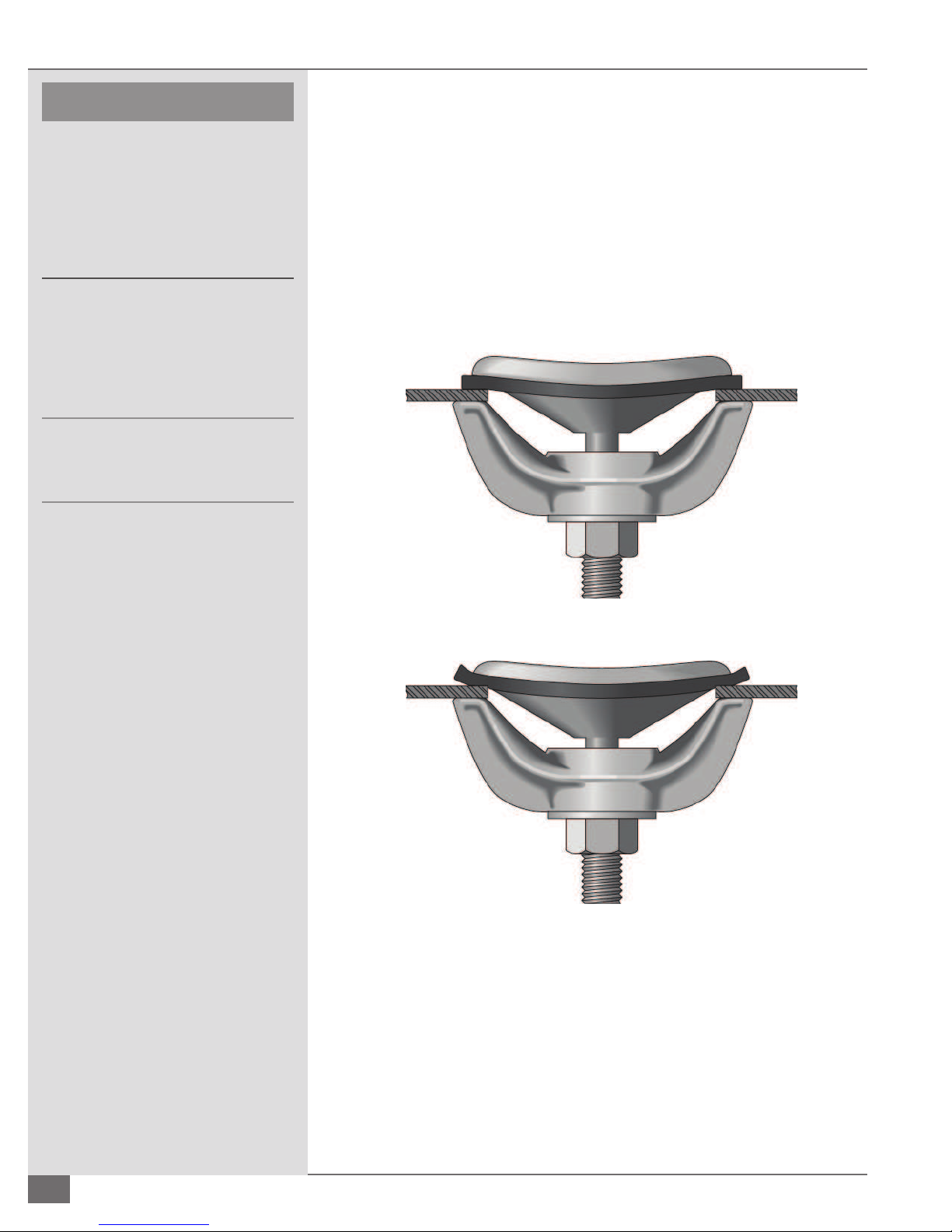
MAINTENANCE VMPW-IOM-2012-1001 SECTION 4
4 CAUTION
All information in this manual is for
reference and guidance purposes,
and does not substitute for required
professional training, conduct,
and strict adherence to applicable
jurisdictional/professional codes and
regulations.
All maintenance procedures should
be completed by trained personnel.
Appropriate training and instructions
are available from the Fulton Service
Department at (315) 298-5121 or your
local Fulton Thermal Representative.
In order to meet warranty conditions,
ensure all appropriate maintenance
activities are performed.
6. Fit the hand hole assembly as follows:
» Place the gasket on the hand hole plate and ensure that it is
seating correctly. Do not use any grease, lubricant, or adhesive.
» Position the plate in the boiler. Set the yoke and tighten the
securing nut su ciently enough to provide a snug t. Verify
the position of the plate in the boiler, then make it hand tight
and then snug with wrench about 1/4 turn. Do not compress
excessively. See Figures 5 and 6.
» Re ll the boiler with fresh water.
FIGURE 5 CORRECT PRESSURE ON GASKET
FIGURE 6 OVERCOMPRESSED GASKET
4-4
© The Fulton Companies 2012
Page 35
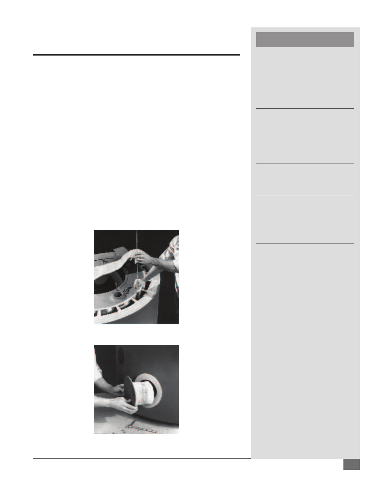
SECTION 4 VMPW-IOM-2012-1001 MAINTENANCE
4 CAUTION
Recommended Annual Maintenance Schedule
All information in this manual is for
The following steps should be carried out annually:
1. Have combustion (CO2, O2, CO) and input checked by appropriate
personnel. See Procedure for Primary Air Adjustment/Inspection and
Procedure for Secondary Air Adjustment/Inspection sections of this
manual.
reference and guidance purposes,
and does not substitute for required
professional training, conduct,
and strict adherence to applicable
jurisdictional/professional codes and
regulations.
2. Clean ues as follows:
» Remove the burner and ue cover plate.
» Wire brush ue passages. See Figure 7.
» Remove clean-out plugs at lowest part of unit (See Figure 8) and
clean the bottom of combustion chamber.
» Remove all soot from the top, and from the clean out plugs at the
bottom, with a vacuum cleaner.
» Replace clean out plugs carefully so as not to damage insulation.
NOTE: ´ Dirty ues can cause air ow restrictions resulting in poor combustion and
loss of e ciency.
All maintenance procedures should
be completed by trained personnel.
Appropriate training and instructions
are available from the Fulton Service
Department at (315) 298-5121 or your
local Fulton Thermal Representative.
In order to meet warranty conditions,
ensure all appropriate maintenance
activities are performed.
If ame and/or gas is permitted to
exist in the blast tube area, back ring
and destruction of electrodes may
result. Ensure primary air adjustment is
adequate to avoid this condition.
FIGURE 7 WIRE BRUSHING THE FLUE PASSAGES
FIGURE 8 REMOVING CLEAN OUT PLUGS
Questions? Call (315) 298-5121, or visit us online at www.fulton.com
4-5
Page 36

MAINTENANCE VMPW-IOM-2012-1001 SECTION 4
! WARNING
All information in this manual is for
reference and guidance purposes,
and does not substitute for required
professional training, conduct,
and strict adherence to applicable
jurisdictional/professional codes and
regulations.
Follow proper lockout / tag out
procedures for the electrical, gas and
water connections. Use caution when
lifting heavy parts.
4 CAUTION
All maintenance procedures should
be completed by trained personnel.
Appropriate training and instructions
are available from the Fulton Service
Department at (315) 298-5121 or your
local Fulton Thermal Representative..
Procedure for Primary Air Adjustment/Inspection
The primary air adjustment control is located at the top righthand side of the
burner assembly. This damper-type air controller is used to introduce air to
the fuel supply of the burner. The purpose of the primary air adjustment is to
proportionally divide the air to the center or outer re chamber.
It is important to the combustion process to maintain proper air mixtures
between the outer service and the center of the blast tube area. Fire should be on
the outside wall and not the blast tube area. Damper positions are as follows:
§ Open: Most of the air is forced down the blast tube, and less air is going
down the outside wall of the de ector face and re chamber.
§ Closed: Less air is forced down the blast tube, and most of the air is going
down the outside wall of the de ector face and re chamber.
NOTE: ´ If it is necessary to close the damper due to a rumbling re, close it slowly
and no more than 1/4th of the distance of the swing of the damper assembly.
Perform inspections as follows:
1. Visually inspect down the blast tube. If heat, ames, or fumes are backing
up through the burner plate area, the damper must be opened up.
After a new Fulton Boiler has been in
operation for several months, pieces
of burned metal will be found in the
space at the bottom of the boiler. These
pieces of metal are the remains of a
light gauge metal form which was
used during manufacture for forming
the boiler insulation. This is a normal
condition and does not a ect the
e ciency or the life of the boiler in any
way.
2. Visually con rm, via the sight glass, that re is completely covering the
walls. If the re is tunneling down or is not on the outside wall, e ciency
will drop. If required, use a micro-amp meter to verify re signal as damper
is moved. Adjust as necessary.
Procedure for Secondary Air Adjustment/Inspection
The secondary air adjustment, or main air control, is located at the fan housing
face. This control is used to supply the burner with excess air needed for good
combustion.
It is important to ensure that the lowest level of excess oxygen is present, while
still maintaining a high level of carbon dioxide and no carbon monoxide. It is
best to measure the ue gas burn with the stack in excess of 420 F (216 C).
Perform inspections as follows:
1. Use an O2 or CO2 test kit to determine the percent of excess air in the
combustion mixture. Adjust main air control as needed to reach optimal
e ciencies. Generally a boiler stack area is used to measure the percent of
oxygen and carbon dioxide in the fuel.
4-6
© The Fulton Companies 2012
Page 37

SECTION 4 VMPW-IOM-2012-1001 MAINTENANCE
2. Adhere to the following:
Gas-Fired Unit It is a good policy to have 3.5-4.0% excess oxygen, which will
provide 10.5-9.5% excess carbon dioxide.
Oil-Fired Unit It is a good policy to have 4.0% excess oxygen, which will
provide 11.0% excess carbon dioxide.
Verify that carbon monoxide level is zero. To do this, use a
Bacharach sni er and CO tubes to prove a clean burn.
Note: Actual values may change when boiler is installed and connected to appropriate stack. Refer to
factory test re sheet for original factory settings.
3. To increase the oxygen in the burner, open air adjustment to right. To
reduce the secondary air, move air adjustment to the left.
NOTE: ´ Too much oxygen will blow the pilot out. Too little oxygen will make the
boiler burn dirty.
Procedure for Flame Scanner Adjustment
Flame scanner adjustments are made with the detectors installed and the burner
running. It is essential to obtain optimum ame signal detection for safe and
continual operation of the control relay.
! WARNING
All information in this manual is for
reference and guidance purposes,
and does not substitute for required
professional training, conduct,
and strict adherence to applicable
jurisdictional/professional codes and
regulations.
4 CAUTION
All maintenance procedures should
be completed by trained personnel.
Appropriate training and instructions
are available from the Fulton Service
Department at (315) 298-5121 or your
local Fulton Thermal Representative.
Ensure that the blower/gas train
assembly is fully supported during
removal/cleaning or burner, as the
transition elbow will be removed.
¡ Gas Unit
Perform adjustment as follows:
1. Close gas cocks on gas train assembly. This will prevent gas from going into
the burner.
2. Turn boiler on while microampmeter is in place.
3. During the ignition trial period, determine if the microampmeter exceeds
#1. If yes, it is likely picking up ignition interference and realignment is
necessary. It may be necessary to place a reduced scanner ori ce plug into
the scanner eye area.
4. Repeat steps 1 - 3 until a reading of #1 or less is achieved on the
microampmeter.
5. Reopen gas cocks and adjust the scanner signal response to maximum
possible signal.
¡ Oil Unit
Perform adjustment as follows:
1. Turn power to panel OFF.
2. Disconnect the hot wire to the oil valves. This will prevent the oil valves
from opening.
Questions? Call (315) 298-5121, or visit us online at www.fulton.com
4-7
Page 38

MAINTENANCE VMPW-IOM-2012-1001 SECTION 4
! WARNING
Extreme caution must be exercised
when checking a failing transformer.
They are capable of producing very
high voltages which may result in
personal injury and death.
3. With microampmeter in place, turn power to the panel ON.
4. During the ignition trial period, determine if the microampmeter exceeds
#1. If yes, it is likely picking up ignition interference and realignment is
necessary. It may be necessary to place a reduced scanner ori ce plug into
the scanner eye area.
5. Repeat steps 1 - 3 until a reading of #1 or less is achieved on the
microampmeter.
6. Turn power OFF. Hook the wire up again, and turn power ON. Start boiler
to ensure the safety light is o .
Procedure for Removing/Cleaning the Burner
Perform the following steps:
1. Remove all bolts that connect the transition elbow to the burner plate, and
to the scroll tube.
2. Pull burner out of unit by ange.
3. Inspect burner and wipe o (do not scrub or use wire brush) any soot or
foreign material that may have accumulated. If available, use compressed
air to clear the burner. Wipe out the inside of the burner with a clean cloth.
4. Reverse removal steps for reinstallation of the burner assembly.
5. Test re the boiler and use a combustion analyzer to ensure that the fuel/
air ratio is set correctly throughout the range. Refer to the Fulton factory
test re sheet for combustion settings.
Procedure for Soot Cleaning
Perform the following:
1. Determine if ues are dirty by checking stack temperature with a stack
thermometer. If temperatures are in excess of 600 F (315 C) while the boiler
is operating, the ues are likely dirty/restricted in some other manner.
NOTE: ´ Usually soot cleaning is performed annually, unless the burner setting has
been altered and excessive soot has been produced as a result.
2. Remove burner and ue cover plates.
3. Using a wire brush, carefully remove soot from ue passages.
4. Clean out plug at lowest part of unit and clean passages between ribs and
bottom of combustion chamber.
4-8
5. Remove all soot with a vacuum cleaner. This may be carried out from the
top and via the inspection doors at the bottom.
6. Replace clean-out plug carefully so as not to damage insulation.
© The Fulton Companies 2012
Page 39

SECTION 4 VMPW-IOM-2012-1001 MAINTENANCE
7. Replace burner and ue cover plates.
After All Repairs or Maintenance
1. Follow “Pre-Start Check List” and all Safety Checks.
2. Fire the boiler and perform combustion safety checks.
3. Analyze combustion throughout the range and verify proper operation of
safety devices.
Troubleshooting
Please refer to Troubleshooting tables that follow.
! WARNING
All information in this manual is for
reference and guidance purposes,
and does not substitute for required
professional training, conduct, and strict
adherence to applicable jurisdictional/
professional codes and regulations.
Questions? Call (315) 298-5121, or visit us online at www.fulton.com
4-9
Page 40
MAINTENANCE VMPW-IOM-2012-1001 SECTION 4
Troubleshooting Gas Fired Boilers
Problem Potential Cause Potential Remedy
Burner Cut-O / Ignition
Failure/ Flame Failure
Power Supply
Gas Supply
Ignition Electrodes
Bad Air Switch
Dirty or defective UV Scanner
Transformer
Flame Safeguard Control
Contact open on air safety
switch
Loose Wire Connection Check connections to all components.
Scanner wiring reversed at panel
box
Protectorelay
Check fuse or circuit; reset or replace, as
necessary.
§ Check to be sure main gas cock is not
closed. Check coil in gas valve with OHM
meter. Replace if faulty. Check gas regulator
setting and readjust as necessary. Check
inlet gas pressure and increase or decrease
as necessary.
§ Check for gas pressure and for intermittent
supply problems. Gas pressure for natural
gas should be 4 in to 11 in wc at the head of
the train.*
Check electrodes for carbon buildup and clean if
necessary. Check for proper adjustment. Readjust
if necessary. Check for cracks in porcelain; if found
replace.
Check for bad air switch by jumpering the two air
switch leads at the terminal block. If the boiler
starts and runs with these terminals jumpered,
the air switch should be replaced.
Check for debris on ame scanner and clean or
replace as needed. Ensure scanner is properly
located.
Check voltage between transformer leads at
terminal block to be sure transformer is being
powered.
Check voltage between ignition terminal and
neutral. Check must be made before control locks
out on safety. If no power, replace control.
Adjust to proper setting
Change to correct terminals.
Check voltage between pilot terminal and
ignition terminal. Check must be made before
control locks out on safety. If zero voltage, clean
relay contacts and recheck for power. If no power,
replace control.
* For natural gas red boilers. Refer to the test re sheet for all other fuels.
4-10
© The Fulton Companies 2012
Page 41

SECTION 4 VMPW-IOM-2012-1001 MAINTENANCE
Troubleshooting Gas Fired Boilers
Problem Potential Cause Potential Remedy
Poor Combustion
Burner back res
Refractories
Not Enough Air/Build-Up on Fan
Wheel (Rich; Burner Hums)
Fuel Valve Adjusted Too High
(Rich; Burner Hums)
Too Much Air (Lean; Unstable
Flame)
Gas Valve Adjusted Too Low
(Lean; Unstable Flame)
Draft
Dirty Flue
Negative Room Pressure
Refractories
Ignition Electrodes
UV Scanner
Draft
Negative Room Pressure
Check refractories to see if they are cracked or
broken in pieces. Replace as necessary.
Check CO2/O2 levels. If rich, disassemble lter
housing and gas train. Look inside inlet to the
fan. If there is build-up on the fan blades, clean
fan. Recheck the CO2/O2 and adjust gas valve as
necessary for all combustion points.
Check CO2/O2 levels. Check gas pressure at
outlet of valve. If the pressure is too high, make
an adjustment at the valve. Be sure to check all
combustion points.
Check fan discharge pressure. If too high,
adjust damper. Check CO2/O2 levels and adjust
gas valve as necessary. Be sure to check all
combustion points.
Check CO2 and O2 levels. Check pressure at outlet
of the valve. If too negative, adjust gas valve as
necessary.
Check draft with a gauge. Draft should be a -.02
in to -.04 in wc with burner o or -.04 in to -.06 in
when operating. May need to install a barometric
damper.
Check ue for carbon buildup or blockage. Clean
ue passages with brush.
Make sure no exhaust fans are running in the
boiler room.
Check refractories to see if they are cracked or
broken in pieces. Replace as necessary.
Check electrodes for carbon buildup and clean if
necessary. Check for proper adjustment. Readjust
if necessary. Check for cracks in porcelain; if found
replace.
Check for debris on ame scanner and clean as
needed. Check for proper location of detector.
Check draft with a gauge. Draft should be a -.02
in to -.04 in wc with burner o or -.04 in to -.06 in
when operating. May need to install a barometric
damper.
Make sure no exhaust fans are running in the
boiler room.
Questions? Call (315) 298-5121, or visit us online at www.fulton.com
4-11
Page 42

MAINTENANCE VMPW-IOM-2012-1001 SECTION 4
Troubleshooting Gas Fired Boilers
Problem Potential Cause Potential Remedy
Check gas pressure coming into gas train. If low,
maintain pressure contact gas company. Should
Boiler will not maintain
temperature
Gas Supply
Dirty Flue
Aquastat
Scale Built up in boiler
Refractories
Boiler Size Boiler may be undersized.
be 7 in to 11 in wc /natural gas. Check coil in gas
valve with AMP meter. Replace if bad. Check gas
regulator setting and readjust as necessary.
Check ue for carbon buildup or blockage. Clean
ue passages with brush.
If power is on, check across aquastats to verify
power through the switch. If bad, replace.
Refer to Recommended Daily Maintenance
section of this manual.
Check refractories to see if they are cracked or
broken in pieces. Replace as necessary.
4-12
© The Fulton Companies 2012
Page 43

SECTION 4 VMPW-IOM-2012-1001 MAINTENANCE
Troubleshooting Oil Fired Boilers
Problem Cause Remedy
Burner Cut O / Ignition
Failure/ Flame Failure
Power Supply
Transformer
Cad Cell
Protectorelay
Oil Supply
Ignition Electrodes
Primary air adjustment
Oil Valve
Oil Pump
Aquastat
Loss of oil prime
Oil Nozzle Check for clogged nozzle; clean or replace
Check fuse or circuit breaker and replace as
necessary.
Check voltage between transformer leads at
terminal block to be sure the terminal is being
powered.
Check for ignition interference. To verify cad cell is
working, place a lit candle in front of photo cell at
the proper time.
Check voltage between pilot terminal and
ignition terminal. Check must be made before
control locks out for safety. If zero voltage, clean
the relay contacts and recheck terminals for
power. If no power, replace control.
Check oil level in supply tank to be sure it is not
below intake line. Fill tank with oil. Check for
clogged nozzle. Clean or replace.
Check electrodes for carbon buildup and clean as
necessary. Check for proper adjustment; readjust
if necessary. Check for cracks in porcelain; replace
if cracked.
Check air adjustment. Air may be blowing re
away from ame sensor.
Check voltage between oil valve leads at terminal
block to be sure oil valve is getting power.
Check for clogged strainer or lter. Remove and
clean. Check for slipping or broken coupling.
Tighten or replace. Check for frozen pump shaft.
Replace.
If power is on, check across aquastats to verify
power through the switch. If bad, replace.
Check all lines for possible air leak in intake line
and tighten. Check for possible restricted intake
line. Replace.
Questions? Call (315) 298-5121, or visit us online at www.fulton.com
4-13
Page 44

MAINTENANCE VMPW-IOM-2012-1001 SECTION 4
Troubleshooting Oil Fired Boilers
Problem Cause Remedy
Check refractories to see if they are sooted,
Poor Combustion
Burner Back Fires
Refractories
S.S. Ring
Oil Nozzle Check for clogged nozzle; clean or replace.
Primary air adjustment
Secondary Air Adjustment
Oil Pump
Draft
Dirty Flue
Refractories
Ignition Electrodes
Primary Air Adjustment
Oil Valve Check for leaky oil valve and replace.
Draft
Loss of Prime
cracked or broken in places. Clean or replace as
needed.
Check to be sure ring is present and ts tight
against the furnace wall.
Check air adjustment. Air may be blowing re
away from ame sensor.
Check main air adjustment to see if it is loose.
Adjust as needed and tighten plate in position.
Check CO2 and O2 levels.
Check for clogged strainer or lter. Remove and
clean. Check for slipping or broken coupling.
Tighten or replace. Check for frozen pump shaft.
Replace.
Check draft with a gauge. Draft should be -0.02 to
-0.04 inches of water column with burner o , or
-0.04 to -0.06 when operating. May need to install
barometric damper.
Check ue for carbon buildup or blockage by
using a stack thermometer placed within one
foot of the stack leaving the boiler area. If stack
temperature is in excess of 600 F while the boiler
is operating, the ues are dirty. Clean as necessary.
Check refractories to see if they are sooted or
broken in places. Clean or replace as needed.
Check electrodes for carbon buildup and clean as
necessary. Check for proper adjustment; readjust
if necessary. Check for cracks in porcelain; replace
if cracked.
Check air adjustment. Air may be blowing re
away from ame sensor.
Check draft with a gauge. Draft should be -0.02 to
-0.04 inches of water column with burner o , or
-0.04 to -0.06 when operating. May need to install
barometric damper.
Check all lines for possible air leak in intake line
and tighten. Check for possible restricted intake
line. Replace.
4-14
© The Fulton Companies 2012
Page 45

SECTION 4 VMPW-IOM-2012-1001 MAINTENANCE
Troubleshooting Oil Fired Boilers
Problem Cause Remedy
Check oil level in supply tank to be sure it is not
Boiler will not maintain
pressure
Oil Supply
Oil Nozzle Check for clogged nozzle; clean or replace.
Oil Valve
Oil Pump
Aquastat
below intake line. Fill tank with oil. Check for
clogged nozzle. Clean or replace.
Check voltage between oil valve leads at terminal
block to be sure oil valve is getting power.
Check for clogged strainer or lter. Remove and
clean. Check for slipping or broken coupling.
Tighten or replace. Check for frozen pump shaft.
Replace.
If power is on, check across aquastats to verify
power through switch. If bad, replace.
Questions? Call (315) 298-5121, or visit us online at www.fulton.com
4-15
Page 46

MAINTENANCE VMPW-IOM-2012-1001 SECTION 4
4-16
© The Fulton Companies 2012
Page 47

WARRANTY & PARTS
INTRODUCTION
INSTALLATION
1
2
OPERATION
MAINTENANCE
WARRANTY & PARTS
3
4
5
Questions? Call (315) 298-5121, or visit us online at www.fulton.com
5-1
Page 48

WARRANTY & PARTS VMPW-IOM-2012-1001 SECTION 5
5-2
© The Fulton Companies 2012
Page 49

SECTION 5 VMPW-IOM-2012-1001 WARRANTY & PARTS
Standard Warranty for Fulton Boilers
Warranty Valid for Models ICS/FB-A, ICW, ICX/FB-F, VMP, VMPW, FB-S, FB-L, FB-W, ICT
Five (5) Year (60 Months) Material and Workmanship Warranty
The pressure vessel is covered against defective material or workmanship for a period of fi ve (5) years from the date
of shipment from the factory. Fulton will repair or replace F.O.B. factory any part of the equipment, as defi ned above,
provided this equipment has been installed, operated and maintained by the buyer in accordance with approved
practices and recommendations made by Fulton. The commissioning agency must also successfully complete and
return the equipment Installation and Operation Checklists to Fulton’s Quality Assurance department. This warranty
covers any failure caused by defective material or workmanship; however, waterside corrosion or scaling is not covered.
Therefore, it is imperative that the boiler water management and chemistry be maintained as outlined in the Installation
and Operation Manual.
Parts Warranty
Fulton will repair or replace F.O.B. factory any part of the equipment of our manufacture that is found to be defective in
workmanship or material within one (1) year of shipment from the factory provided this equipment has been installed,
operated and maintained by the buyer in accordance with approved practices and recommendations made by both
Fulton and the component manufacturers and the commissioning agency has successfully completed and returned the
equipment Installation and Operation Checklists to Fulton’s Quality Assurance department.
General
Fulton shall be notifi ed in writing as soon as any defect becomes apparent. This warranty does not include freight,
handling or labor charges of any kind. These warranties are contingent upon the proper sizing, installation, operation
and maintenance of the boiler and peripheral components and equipment. Warranties valid only if installed, operated,
and maintained as outlined in the Fulton Installation and Operation Manual. No Sales Manager or other representative
of Fulton other than the Quality Manager or an offi cer of the company has warranty authority. Fulton will not pay any
charges unless they were pre-approved, in writing, by the Fulton Quality Manager. This warranty is exclusive and in lieu
of all other warranties, expressed or implied, including but not limited to the implied warranties of merchantability and
fi tness for a particular purpose. Fulton shall in no event be liable for any consequential or incidental damages arising in
any way, including but not limited to any loss of profi ts or business, even if the Fulton Companies has been advised of
the possibility of such damages. Fulton’s liability shall never exceed the amount paid for the original equipment found
to be defective. To activate the warranty for this product, the appropriate commissioning sheets must be completed and
returned to the Fulton Quality Assurance department for review and approval.
Effective 09.01.2010
Questions? Call (315) 298-5121, or visit us online at www.fulton.com
5-3
Page 50

PARTS & WARRANTY VMPW-IOM-2012-1001 SECTION 5
! WARNING
Use of non-factory authorized
replacement parts is not recommended
for this equipment. Use of non-factory
authorized parts may jeopardize safety
and system performance, and voids the
product warranty.
Parts
Spare and replacement parts may be ordered from your local representative or
through the Fulton Companies. When ordering replacement parts, please have
the model number and serial number of your Fulton boiler ready. Factory-direct
replacement parts must be used to ensure proper equipment operation and
adherance with warranty requirements. Contact Fulton Companies at (315) 2985121 for further information.
5-4
© The Fulton Companies 2012
Page 51

Page 52

No part of this Installation, Operation, and Maintenance manual
may be reproduced in any form or by any means without
permission in writing from the Fulton Companies.
Fulton Boiler Works, Inc., Fulton Heating Solutions, Inc. & Fulton Thermal
Corporation are part of the Fulton Group of Companies, a global manufacturer
of steam, hot water and thermal uid heat transfer systems.
© The Fulton Companies 2012
The heat transfer innovators.
The Fulton Companies
972 Centerville Road, Pulaski, NY 13142
Call: (315) 298-5121 • Fax: (315) 298-6390
www.fulton.com
VMPW-IOM-2012-1001
 Loading...