

Page 1
INSTALLATION AND
OPERATION MANUAL
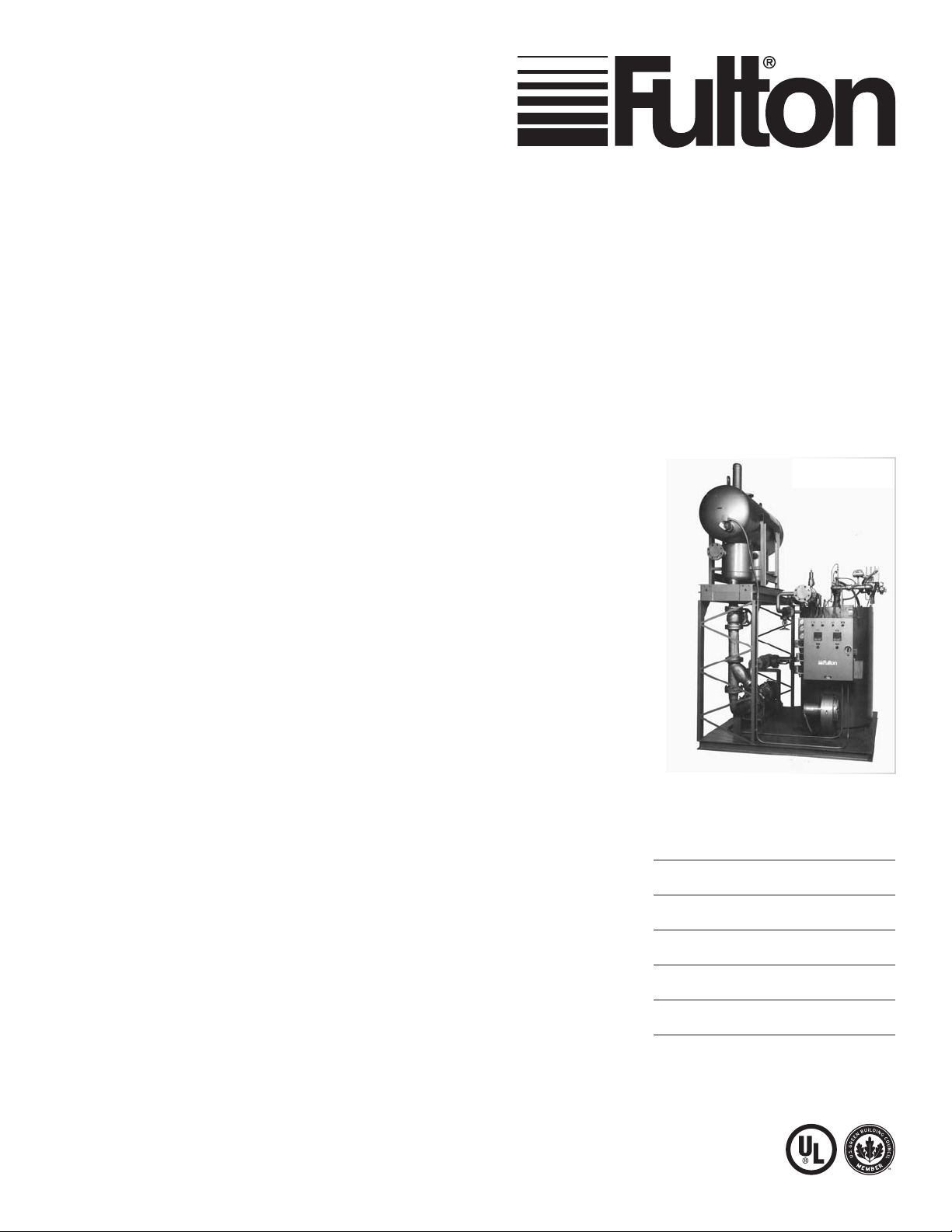
Vertical Coil Design
Thermal Fluid Heaters
Models FT-C and FT-S
Serial / National
Board Number
Model
Fulton Order
Sold To
Job Name
Date
FTCS-IOM-2013-1114
Page 2

Page 3

INTRODUCTION
INTRODUCTION
1
INSTALLATION
2
OPERATION
MAINTENANCE
PARTS & WARRANTY
3
4
5
Questions? Call (315) 298-5121, or visit us online at www.fulton.com
1-1
Page 4

INTRODUCTION FTCS-IOM-2013-1114 SECTION 1
Overview
Prior to shipment, the following inspections and tests are
made to ensure the highest standards of manufacturing for
our customers:
Material inspections
Manufacturing process inspections
American Society of Mechanical Engineers (ASME)
welding inspection
ASME hydrostatic test inspection
Electrical components inspection
Operating test
Final engineering inspection
Crating inspection
This manual is provided as a guide to the correct operation
and maintenance of your Fulton equipment, and should be
read in its entirety and be made permanently available to the
sta responsible for the operation of the heater. It should not,
however, be considered as a complete code of practice, nor
should it replace existing codes or standards which may be
applicable. Fulton reserves the right to change any part of
this installation, operation and maintenance manual.
Installation, start-up, and maintenance of this equipment
can be hazardous and requires trained, quali ed installers
and service personnel. In order to meet Fulton warranty
requirements, this unit must be commissioned by a Fulton
Factory Technician. Trained personnel are responsible
for the operation and maintenance of this product, and
for the safety assurance of operation and maintenance
processes.
Warnings & Cautions
WARNINGS and CAUTIONS appear in various chapters of this
manual. It is critical that all personnel read and adhere to all
information contained in WARNINGS and CAUTIONS.
WARNINGS must be observed to prevent serious injury
or death to personnel.
CAUTIONS must be observed to prevent damage
or destruction of equipment or loss of operating
e ectiveness.
All Warnings and Cautions are for reference and guidance
purposes, and do not substitute for required professional
training, conduct, and strict adherence to applicable
jurisdictional/professional codes or regulations.
Disclaimers and Local Codes
Installation of the equipment shall conform to all the
requirements or all national, state and local codes established
by the authorities having jurisdiction or, in the absence
of such requirements, in the US to the National Fuel Gas
Code ANSI Z2231/NFPA 54 latest edition, and the speci c
instructions in this manual. Authorities having jurisdiction
should be consulted prior to installation.
The boiler heat exchanger is manufactured and stamped
in accordance with ASME Boiler and Pressure Vessel Code,
Section VIII, Div. 1 or Section I. It is the responsibility of the
customer to ensure equipment conforms to requirements
and codes.
Do not install, operate, service or repair any component
of this equipment unless you are quali ed and fully
understand all requirements and procedures.
When working on this equipment, observe all warnings,
cautions, and notes in literature, on stickers and labels, and
any additional safety precautions that apply. Follow all safety
codes and wear appropriate safety protection. Follow all
jurisdictional codes and consult any jursidictional authorities
prior to installation.
1-2
© The Fulton Companies 2013
Page 5

FTCS-IOM-2013-1114 TABLE OF CONTENTS
Introduction 1-1
Overview .............................................................................................................. 1-2
Warnings & Cautions ............................................................................................ 1-2
Disclaimers and Local Codes ................................................................................ 1-2
Installation 2-1
Placement & Rigging ........................................................................................... 2-2
Clearances & Serviceability .................................................................................. 2-3
Environment, Ventilation and Combustion Air Requirements ............................ 2-4
Utilities ................................................................................................................. 2-7
THE GAS SUPPLY ..........................................................................................................................2 7
THE OIL SUPPLY .........................................................................................................................210
Instrument Air .................................................................................................... 2-10
Electrical Supply ................................................................................................ 2-11
Thermal Fluids .................................................................................................... 2-12
THERMAL FLUIDS AT ELEVATED TEMPERATURES ....................................................................212
SELECTING A THERMAL FLUID ..................................................................................................212
ROUTINE ANALYSIS OF HEAT TRANSFER FLUID ........................................................................2 14
THERMAL FLUID BREAKDOWN .................................................................................................214
Piping Speci cations .......................................................................................... 2-15
Insulation ........................................................................................................... 2-21
System Interfaces ............................................................................................... 2-21
HEATER CONNECTIONS ..............................................................................................................2 21
THERMAL FLUID CIRCULATING PUMP .....................................................................................222
REQUIREMENTS FOR AIR COOLED PUMPS ..............................................................................2 23
REQUIREMENTS FOR WATER COOLED PUMPS ......................................................................... 223
COMBINATION DEAERATOR/THERMAL BUFFER/EXPANSION TANK ........................................2 24
SIZING THE EXPANSION TANK FOR THE SYSTEM ......................................................................226
PRESSURIZED SYSTEMS ............................................................................................................227
VENT CONNECTIONS ..................................................................................................................228
CATCH TANK ............................................................................................................................... 229
DRAIN/FILL CONNECTION .........................................................................................................229
PRESSURE GAUGES ...................................................................................................................229
THERMOMETERS .......................................................................................................................230
VALVES .......................................................................................................................................230
AUTOMATIC FLUID CONTROL VALVES .......................................................................................231
BYPASS VALVES ........................................................................................................................ 231
Assembly of Fulton Multi-Skid Engineered Systems ......................................... 2-31
Stack and Flue .................................................................................................... 2-32
Testing ................................................................................................................ 2-34
Operation 3-1
Start-Up Preparation & Installation Review ........................................................ 3-2
Fill the System ...................................................................................................... 3-3
FILLING PROCEDURE FOR SYSTEMS OPEN TO ATMOSPHERE ....................................................33
FILLING PROCEDURE FOR SYSTEMS EQUIPPED WITH INERT BLANKETS .................................34
Circulating Pump .................................................................................................. 3-5
PUMP WITH MECHANICAL/AIR COOLED SEAL ...........................................................................35
PUMP WITH PACKED SEAL ..........................................................................................................36
Start-Up Service ................................................................................................... 3-6
Initial Start-Up ..................................................................................................... 3-7
COLD CIRCULATION......................................................................................................................37
FILTERING THE SYSTEM ...............................................................................................................3 8
BOILOUT .......................................................................................................................................38
COMBUSTION ............................................................................................................................... 39
Flame Programmers .......................................................................................... 3-14
SIEMENS LINKAGELESS MODULATION, LMV 51 ...................................................................... 314
Operating Controls ............................................................................................. 3-19
LIQUID LEVEL SWITCH WHEN COMBINATION TANK IS SUPPLIED ........................................3 19
AIR SAFETY SWITCH ..................................................................................................................319
BLOWER M OTOR STARTER .........................................................................................................319
PUMP M OTOR S TARTE R .............................................................................................................320
DIFFERENTIAL PRESSURE SWITCH ...........................................................................................3 20
HIGH AND LOW FLUID PRESSURE SWITCHES ...........................................................................3 21
GAS PRESSURE SWITCH ............................................................................................................322
OPERATING TEMPERATURE CONTROLS ....................................................................................322
HIGH TEMPERATURE LIMIT SWITCHES SAFETY ......................................................................323
OPERATING LIMIT CONTROLLER ...............................................................................................324
ON/OFF CONTROLS ....................................................................................................................324
MODULATING CONTROLS ..........................................................................................................3 24
PRESSURE GAUGES .................................................................................................................... 324
TEST OF IGNITION SAFETY SYSTEM SHUTOFF ..........................................................................325
CYCLE TESTING ...........................................................................................................................325
Required Pressure Drop Across the Heater ......................................................... 3-26
Procedure for First Shutdown ............................................................................ 3-27
Daily Start-Up ..................................................................................................... 3-27
Daily Shutdown .................................................................................................. 3-28
Before Leaving the Installation .......................................................................... 3-28
Maintenance 4-1
Required Equipment ............................................................................................ 4-2
Required Maintenance at First Shutdown ........................................................... 4-2
Daily Maintenance Schedule ................................................................................ 4-2
Weekly Maintenance Schedule ............................................................................ 4-4
Monthly Maintenance Schedule .......................................................................... 4-4
Semi-Annual Maintenance Schedule .................................................................. 4-5
Annual Maintenance Schedule ........................................................................... 4-5
General Maintenance Procedures ....................................................................... 4-5
LUBRICATION ...............................................................................................................................45
SOOT CLEANING ..........................................................................................................................46
Safety Check Procedures ..................................................................................... 4-6
Questions? Call (315) 298-5121, or visit us online at www.fulton.com
0-1
Page 6

TABLE OF CONTENTS FTCS-IOM-2013-1114
LIQUID LEVEL SWITCH ................................................................................................................46
STACK LIMIT .................................................................................................................................46
DIFFERENTIAL PRESSURE SWITCH ............................................................................................. 47
LOW INLET PRESSURE SWITCH ...................................................................................................4 7
HIGH INLET PRESSURE SWITCH ..................................................................................................47
HIGH OUTLET PRESSURE SWITCH ...............................................................................................4 7
AIR SWITCH .................................................................................................................................. 48
AIR FILTER BOX SWITCH ..............................................................................................................48
TEMPERATURE LIMITS ..............................................................................................................48
HIGH/LOW GAS PRESSURE SWITCH ...........................................................................................48
Troubleshooting ................................................................................................... 4-9
FLOW CIRCUIT/ CIRCULATING PUMPS ..................................................................................... 49
Parts and Warranty 5-2
Standard Warranty for Fulton Thermal Fluid Heaters .......................................... 5-3
0-2
© The Fulton Companies 2013
Page 7

INSTALLATION
INTRODUCTION
1
INSTALLATION
2
OPERATION
MAINTENANCE
PARTS & WARRANTY
3
4
5
Questions? Call (315) 298-5121, or visit us online at www.fulton.com
2-1
Page 8

INSTALLATION FTCS-IOM-2013-1114 SECTION 2
! WARNING
All information in this manual is for
reference and guidance purposes,
and does not substitute for required
professional training, conduct,
and strict adherence to applicable
jurisdictional/professional codes and
regulations.
Unless otherwise noted, this heater is
certi ed for indoor installation only.
A competent rigger experienced in
handling heavy equipment should
handle rigging your equipment into
position.
The equipment must be installed on a
non-combustible surface.
Ensure all labels on the heater are
legible. All connections and safety
devices, both mechanical and
electrical, must be kept clean, with
ease of access for inspection, use and
maintenance.
Do not store or use gasoline or other
ammable vapors and liquids or
corrosive materials in the vicinity of
this or any other appliances.
Placement & Rigging
Proper placement of your Fulton Product (see Figures 1 and 2, and Tables 1
and 2) is essential. Attention paid to the following points will save a great deal
of di culty in the future. Correct placement is the rst step to trouble-free
installation, operation and maintenance.
Adhere to the following for equipment placement and rigging:
1. Consult authorities with jurisdiction over any national or local codes
(including but not limited to National Fire Protection Agency (NFPA),
American National Standards Institute (ANSI), Underwriters Laboratories
(UL), SCA, and ASME, which might be applicable to heater applications
before beginning.
2. Make appropriate determinations for placement, based on the following:
Check building speci cations and Table 3 for permissible oor loading.
Ensure the equipment is to be placed on a non-combustible level base
with adequate clearances from combustible materials. See Clearances &
Serviceability section.
Locate heater as close as possible to the place where the heat will be used
in order to keep pipe work costs to a minimum.
Ensure that there is adequate clearance around the unit to provide
access for operators and maintenance personnel to all parts of the
equipment. Ensure also that clearance provides for component removal for
maintenance. See Clearances & Serviceability section. The equipment
should be placed in a suitable heater house or well ventilated separate
room through which personnel do not normally pass. The layout should
eliminate tra c in potentially hazardous areas. For instance, the service
engineer or the operator should not have to pass exposed, hot pipe work
to make adjustments to the heater controls.
4 CAUTION
Do not allow weight to bear on
equipment components to prevent
damage.
2-2
Ensure the equipment is to be placed in such a way that the electrical
components are protected from exposure to water or excessive humidity.
3. Determine rigging procedure, based on the following:
Units are shipped upright and crated for forklift transport. Once
uncrated, all units can be transported with a forklift with the exception of
freestanding models FT-0080C, FT-0120C, FT-0160C and FT-0240C. These
four models can only be lifted for unloading and moving by means of
lifting lugs at the top of the heaters. All skidded units can be moved with
forklifts.
If means of lifting are not available, place rollers beneath the frame of the
equipment for guidance to the position of where it is to be installed.
Under no circumstances allow weight to bear on the jacket, control panel,
burner, fuel train or fan housing of any Fulton heater.
4. Install a 4 inch (102 mm) curb completely around the unit. In the event of a
large spill, this will help contain the uid.
© The Fulton Companies 2013
Page 9

SECTION 2 FTCS-IOM-2013-1114 INSTALLATION
Clearances & Serviceability
Adhere to the following for equipment clearances and serviceability:
1. Ensure appropriate front, back, sides and top clearances are met. This
will allow access around the equipment to facilitate maintenance and a
safe work environment, and ensure technicians will commission the unit.
Technicians will not commence commissioning if hazardous conditions
exist.
2. Place heater with clearances to unprotected combustible materials,
including plaster or combustible supports, not less than the following:
Heater Front 36” (1m)
Heater Sides 18” (0.5 m)
Heater Rear 18” (0.5 m)
Flue Pipe 18” (0.5 m)
Minimum clearances for personnel access and burner removal: refer to
Table 4.
» In cases where the available height is insu cient, a roof or ceiling
trap must be considered. Fulton Vertical Coil design units need
su cient headroom for burner maintenance. Larger models
of the vertical coil design unit (FT-0320C and above) require an
access ladder/gantry to be provided by the customer to allow
clear access to the top of the heater for maintenance purposes.
Fulton Thermal Corporation will advise on the suitability of the
access provided and will provide assistance that may be required
in this respect.
» Access provision should avoid possible contact with hot
pipework, ues etc.
! WARNING
All information in this manual is for
reference and guidance purposes,
and does not substitute for required
professional training, conduct,
and strict adherence to applicable
jurisdictional/professional codes and
regulations.
Crystalline silica may be present
in components of this equipment.
Exposure to crystalline silica may
pose signi cant health hazards,
including but not limited to eye and
respiratory system damage. Per
the Centers for Disease Control and
Prevention (CDC) and Occupational
Safety and Health Administration
(OSHA), appropriate personal
protective equipment must be worn
to minimize exposure to hazardous
substances. Refer to most current
guidelines o ered by the CDC and
OSHA for more information, including
personal protective equipment
recommendations.
Failure to provide required and
safe access to the equipment
could impede commissioning and
maintenance. Service technicians
are instructed not to commence
commissioning if hazardous
conditions exist.
NOTE: Burners may weigh up to 550 lbs (249 kg) depending on the type and
con guration.
NOTE: For UL listed units, see the speci cation plate on the Fulton Thermal Fluid
Heater for these clearances.
3. Pipes must not be run within 10” (254 mm) of any control cabinets or
combustible material.
4. Verify that all clearances are acceptable with the local ordinances.
Questions? Call (315) 298-5121, or visit us online at www.fulton.com
Failure to provide proper minimum
clearances between equipment and
combustible materials may result in
re.
2-3
Page 10
INSTALLATION FTCS-IOM-2013-1114 SECTION 2
Environment, Ventilation and
Combustion Air Requirements
Ventilation must be su cient to maintain a building
temperature of 120°F (49°C) or less. Consistent proper
ventilation of the equipment room is essential for good
combustion.
NOTE: When calculating ventilation requirements, heat
losses from the Fulton equipment (and other equipment)
should be considered.
Adhere to the following to meet ventilation and combustion
air requirements:
1. Install two fresh air openings, one at a low level, 24” (610
mm) from the oor, and one at a higher level on the
equipment room wall. This will provide a ow of air to
exhaust the hot air from the equipment room.
2. Ensure the burner has an adequate supply of air. Based
on NBIC recommendations, unobstructed air openings
must be sized on the basis of 0.5 square inch of free
area per 1,000 BTU/hr input maximum fuel input of
the combined burners in the equipment room or as
speci ed by applicable codes.
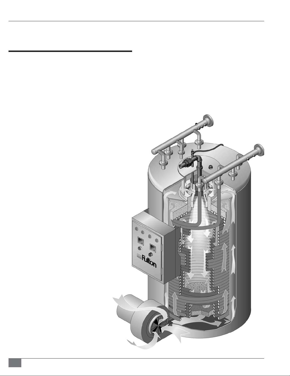
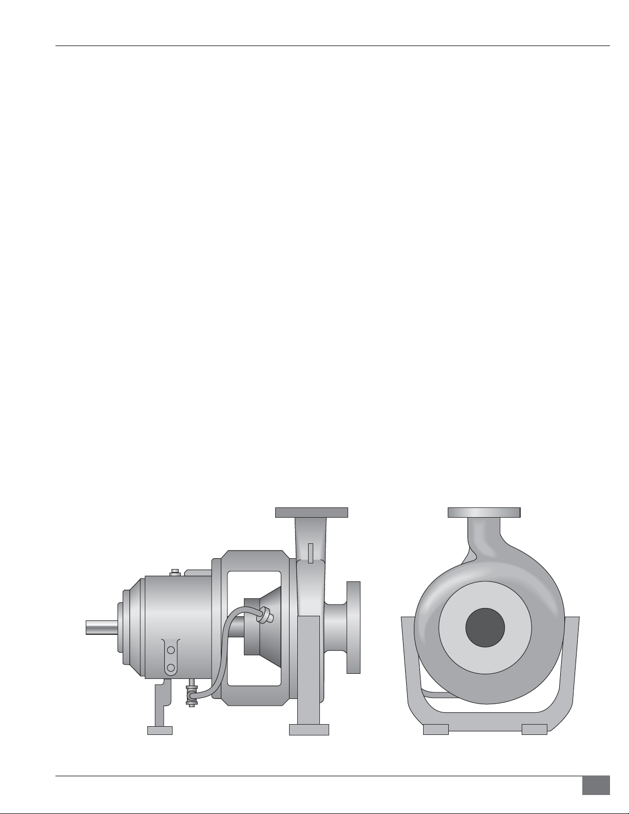
FIGURE 1 COMPONENT VIEW OF THE FTC / FTS
THERMAL FLUID HEATER
Legend
A - Fluid Outlet
B - Fluid Inlet
C - Top Mounted Burner
D - Control Panel
E - Fan Inlet
Notes
1. Thermal uid heater is of four-pass combustion
design.
D
A
B
C
2. First pass (radiant): combustion air enters burner fan
and travels upward between inner and outer jacket
before it enters top-mounted burner.
3. Second pass (convection): Gases travel back across
the inner row of coils.
4. Third pass (convection): Gases continue back down
between inner and outer coil.
5. Fourth pass: Upward between the outer coil and
inner jacket to the ue outlet.
2-4
E
© The Fulton Companies 2013
Page 11

SECTION 2 FTCS-IOM-2013-1114 INSTALLATION
TABLE 1 SPECIFICATIONS COIL DESIGN THERMAL FLUID HEATER
Model FT-C 0080 0120 0160 0240 0320 0400 0600 0800 1000 1200 1400
Heat Output
Thermal Fluid Content
Recommended Flow Rate
Typical Circulating Pump Motor
Typical Burner Motor*
Fuel Consumption @
Full Output No.2 Oil
Natural Gas
1000 BTU/HR
1000 KCAL/HR
GAL
LITERS
GPM
M3/HR
HP
KW
HP
KW
GPH
LITER/HR
FT3/HR
M3/HR
800
200
11.4
7.5
1.5
1.1
7.1
998
38.3
1,200
300
10
38
50
10
27
7.5
2.2
10.7
40.6
1,498
42.4
1,600
400
21
80
75
17
10
3
100
22.7
11.2
2.2
14.3
54.1
1,998
56.5
2,400
600
19
72
15
3
116
150
11.2
2.2
21.4
2,999
84.9
3,200
800
31
34
15
3
81
258
250
56.8
14.9
3.7
108.8
4,000
113.2
4,000
1,000
68
20
5
28
288
250
56.8
14.9
3.7
35.3
136
4,997
141.5
6,000
1,500
76
20
5
132
498
375
85.2
22.5
201
7,498
212.3
7.5
5.6
8,000
2,000
113.6
30
53
29.5
11.2
69.3
263.7
9,997
171
648
500
40
15
283
10,000
2,500
290
1,097
615
139
37.3
87.1
329.6
12,496
353.8
12,000
3,000
1,448
50
37.3
20
15
104.5
395.5
14,998
424.6
383
730
167
50
20
15
14,000
3,500
460
1,741
800
182
60
45
20
15
122
461.5
17,500
495.5
* Std burner, single fuel applications.
Notes: Voltage 3 Phase for Burner and Pump - Each unit has an incorporated stepdown transformer. Fuel up to No. 6 Oil Available for Large Units (FT-0600-C and larger). E ciency up to 80%
Minimum Based on High Heating Value of the Fuel (No. 2 Oil @ 140,000 BTU/GHHV; Natural Gas @ 1000 BTU/ft3HHV. Modulation 3 to 1 Turn Down Ratio (5 to 1 for 320). Optional on FT-0080, 0120,
and 0160-Standard on all others. Circulating pump motor sizes based on standard pressure (55 PSIG) and viscosity 1 cs, speci c gravity 0.7, with 25-37 PSID available head for installation.
TABLE 2 DIMENSIONSCOIL DESIGN THERMAL FLUID HEATER SEE FIGURE 2
Model FT-C 0080 0120 0160 0240 0320 0400 0600 0800 1000 1200 1400
Heater Inlet/ Outlet Connections
(A) Overall Height
(B) Overall Width
(C) Overall Depth
(D) Flue Outlet Diameter
Recommended Vertical
Stack Diameter
Approximate Dry Weight
MM
MM
MM
MM
MM
MM
LBS
KG
IN
IN
IN
IN
IN
IN
1.25
73.7
1,872
31.6
803
46.2
1,173
254
254
1,500
700
32
10
10
1.5
38
80.7
2,050
34.4
873
60.6
1,540
10
254
12
304
2,100
950
51
80.6
2,046
45.9
1,165
60.6
1,540
10
254
12
304
2,550
1,150
2
2.5
64
89.7
2,278
50.1
1,273
66.6
1,691
12
305
14
356
3,400
1,550
76.3
100.6
2,556
49.3
1,252
80.6
2,046
14
356
18
457
5,300
2,400
3
112.4
2,856
49.3
1,252
80.6
2,046
356
457
5,300
2,400
3
76
14
18
102
143.6
3,648
63.4
1,611
88.1
2,237
457
558
8,250
3.750
4
18
22
102
143
3,632
70.5
1,791
107.75
2,736
508
609
11,450
5,200
4
20
24
152
146.5
3,721
2,413
135.1
3,432
508
609
19,250
8,750
6
95
20
24
152
146.4
3,718
108.4
2,753
152.9
3,882
22
559
26
661
21,700
9,850
6
6
152
163.1
4,144
108.4
2,753
152.9
3,882
22
559
26
661
23,000
10,455
Questions? Call (315) 298-5121, or visit us online at www.fulton.com
2-5
Page 12
INSTALLATION FTCS-IOM-2013-1114 SECTION 2
! WARNING
All information in this manual is for
reference and guidance purposes,
and does not substitute for required
professional training, conduct,
and strict adherence to applicable
jurisdictional/professional codes and
regulations.
A quali ed installer, service agency
or the gas supplier must perform
installation and service on the fuel
delivery system.
Do not use matches, candles, ame or
other sources of ignition to check for
gas leaks.
WHAT TO DO IF YOU SMELL GAS:
Do not try to light the appliance.
Do not touch any electrical switch.
Do not use any phone in the building.
Leave building and contact gas
supplier from neighbor’s phone. If you
cannot reach gas supplier, phone the
re department.
3. Ensure the equipment room air supply openings are kept clear at all times.
4. See Table 5 for minimum make-up air required and the recommended area
of each opening for each model.
TABLE 3 APPROXIMATE FLOOR LOADING
Model Heater Only*
FT-0080C 500
FT-0120C 400
FT-0160C 450
FT-0240C 450
FT-0320C 450
FT-0400C 450
FT-0600C 550
FT-0800C 500
FT-1000C 500
FT-1200C 400
FT-1400C 450
FT-0400S 675
FT-0600S 675
FT-0800S 525
*All weights are lbs/ft
TABLE 4 RECOMMENDED MINIMUM CLEARANCES FOR PERSONNEL ACCESS/BURNER
2
REMOVAL
When making gas piping joints,
maintain proper ventilation to reduce
breathing hazards.
An exhaust fan may draw products of
combustion into the work environment
creating a possible hazard to personnel.
4 CAUTION
It is essential that only fresh air be
allowed to enter the combustion air
system. Foreign substances, such
as combustible volatiles and lint in
the combustion system can create
hazardous conditions. If foreign
substances can enter the air stream, the
combustion air inlet must be piped to
an outside location. Failure to do so will
void the warranty.
To avoid failures due to poor
combustion, ensure make-up air system
is properly designed.
Model Inches (Meters)
FT-0080C 109 (2.8)
FT-0120C 115 (3.0)
FT-0160C 119 (3.1)
FT-0240C 125 (3.2)
FT-0320C 133 (3.4)
FT-0400C 145 (3.7)
FT-0600C 171 (4.4)
FT-0800C 172 (4.4)
FT-1000C 173 (4.4)
FT-1200C 172 (4.4)
FT-1400C 188 (4.8)
FT-0400S 162 (4.2)
FT-0600S 170 (4.4)
FT-0800S 171 (4.4)
5. If positive forced ventilation is adopted, ensure that there will be no
appreciable pressure variation in the equipment room.
6. Avoid ventilation which creates a negative pressure in the building as it
will seriously a ect combustion and proper operation of the stack. Please
note that exhaust fans or similar equipment can create a down draft in the
chimney or starve the burner’s air supply. Either case may result in poor
2-6
© The Fulton Companies 2013
Page 13

SECTION 2 FTCS-IOM-2013-1114 INSTALLATION
combustion or nuisance failures.
TABLE 5 MINIMUM MAKEUP AIR REQUIREMENTS AND
RECOMMENDED AREA OF OPENING FOR VENTS
Model Minimum
Make-Up
Air (SCFM)*
FT-0080C 200 400 135
FT-0120C 300 600 205
FT-0160C 400 800 270
FT-0240C 600 1200 400
FT-0320C 800 1600 535
FT-0400C 1000 2000 670
FT-0600C 1500 3000 1000
FT-0800C 2000 4000 1335
FT-1000C 2500 5000 1670
FT-1200C 3000 6000 2000
FT-1400C 3500 7000 2335
FT-0400S 1000 2000 670
FT-0600S 1500 3000 1000
FT-0800S 2500 4000 1335
*Minimum make-up air requirements are based on 25% excess air at high re.
**Opening areas are calculated based input of a single heater and do not account
for the ventilation needs of the equipment room. These measurements are
subject to state and local regulations.
Opening Area
(in2)**Lower
Ven t
Opening
Area (in2)
Upper Vent
NOTE: A properly designed make-up air system in the
equipment room will preclude these possibilities and is
required to maintain proper combustion.
7. Eliminate potential for high risk situations for particulate
matter to be in the combustion air supply (e.g., as a
result of construction and maintenance activities).
Utilities
The Gas Supply
Adhere to the following for gas supply installation:
1. Install gas piping in accordance with all applicable
codes.
2. Ensure pipe and ttings used are new and free of dirt or
other deposits.
3. Ensure piping is of the proper size for adequate gas
supply to the gas head assembly. Consult your gas
company for speci c recommendations.
4. When making gas piping joints, use a sealing
compound resistant to the action of lique ed
petroleum gases. Do not use Te on tape on gas line
heads.
5. Ensure no piping stresses are transmitted to the
equipment. The equipment shall not be used as a pipe
anchor.
6. Ensure all vent connections on diaphragms, gas valves,
pressure regulators, and pressure switches (gas- red
units) are vented per local code.
7. On gas- red units with NFPA valve trains, ensure the
vent valve is piped to atmosphere per local code. See
Figure 4.
FIGURE 2 DIMENSIONS REFER TO TABLE 2
Questions? Call (315) 298-5121, or visit us online at www.fulton.com
2-7
Page 14
INSTALLATION FTCS-IOM-2013-1114 SECTION 2
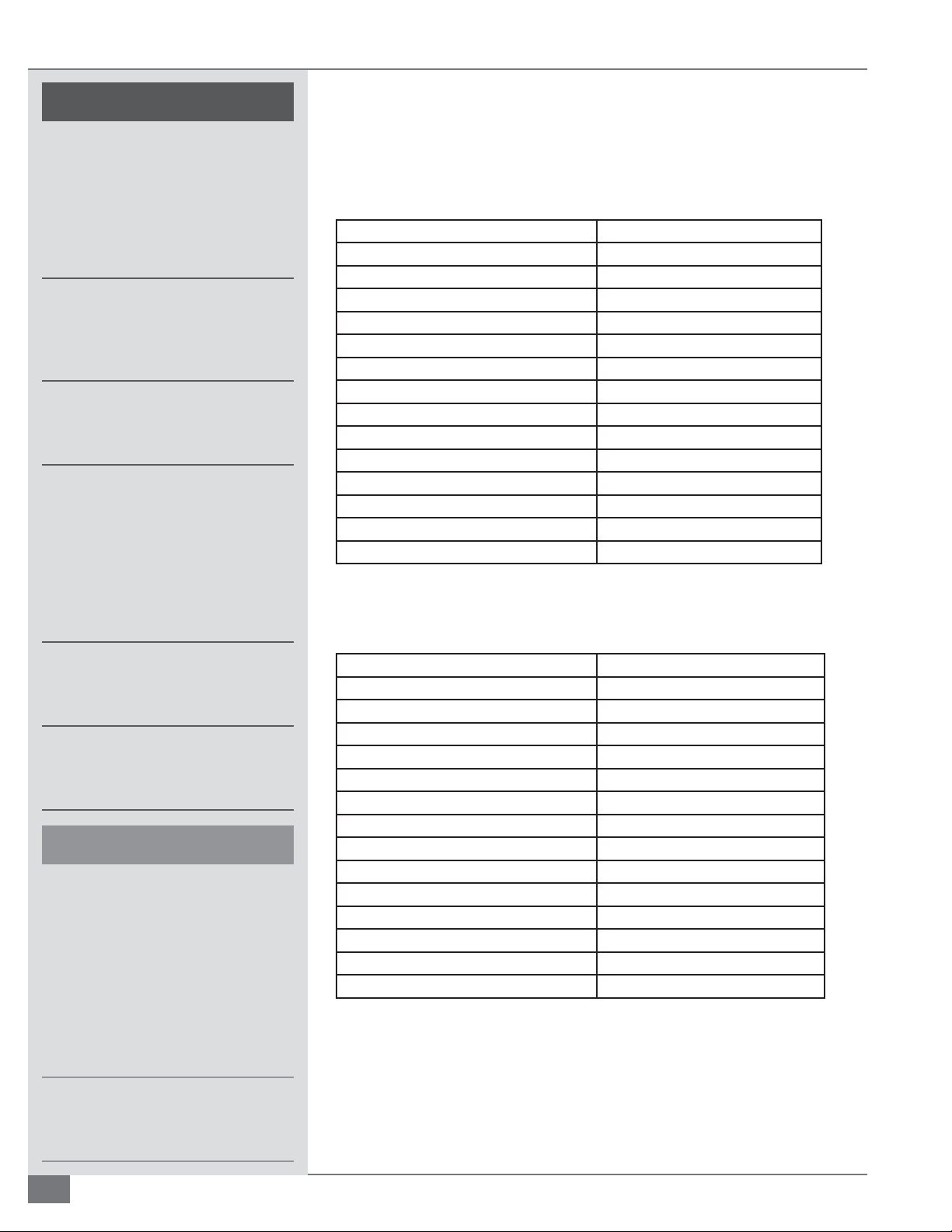
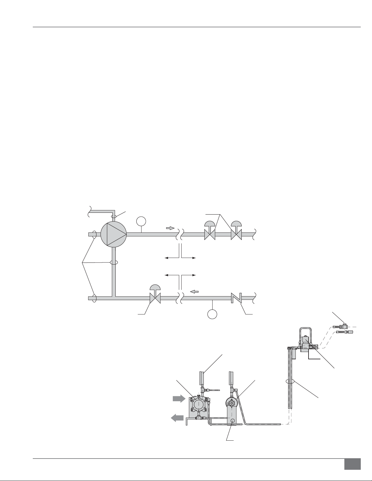
2” N.P.T. Gas
Connection
Main Gas
Regulator
Manual Gas
Valv e
Gas Safety
Shuto Valve
Pilot Gas
Valv e
Pilot Gas
Regulator
Buttery
Valv e
FIGURE 3 TYPICAL GASFIRED MODULATED CSD1 FUEL TRAIN
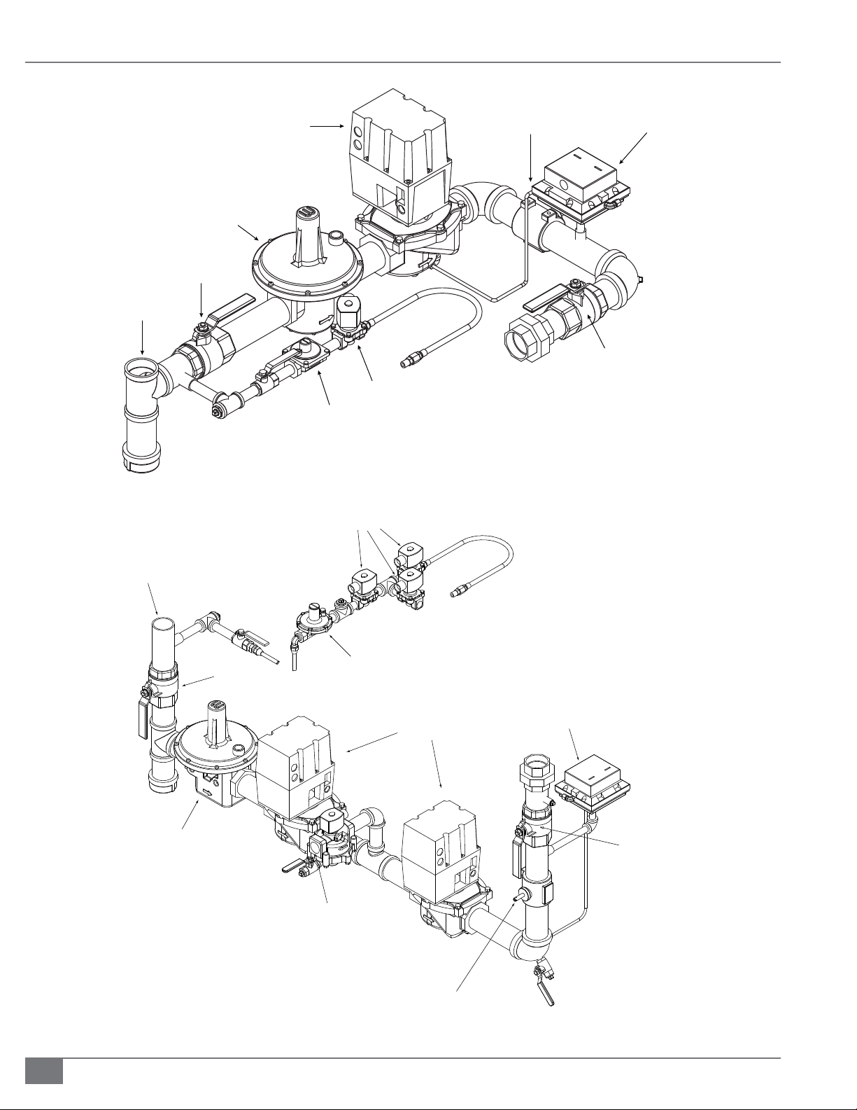
Pilot Gas
Valves
HI / LOW
Gas Pressure Switch
Manual Gas
Valv e
2” N.P.T. Gas
Connection
Manual Gas
Regulator
Manual Gas
Valve
Vent Valve
Pilot Gas
Regulator
Gas Safety
Shutoff Valve
HI/LOW
Gas Pressure Switch
Manual Gas
Valve
2-8
Butterfly
Valve
FIGURE 4 TYPICAL GASFIRED MODULATED NFPA FUEL TRAIN
© The Fulton Companies 2013
Page 15
SECTION 2 FTCS-IOM-2013-1114 INSTALLATION
8. During any pressure testing of the system at pressures
in excess of 1/2 psig (14 inch W.C.)., disconnect the
heater at the heater manual shuto valve (located at
the end of the supplied gas train) from the gas supply
piping system.
9. Ensure the supply pressure is regulated by a nonstacking, tight, shut-o regulator.
10. Arrange gas piping so that it does not interfere with
any cover or burner, inhibit service or maintenance,
or prevent access between unit and walls or another
unit.The burner assembly and gas controls terminate
at a manual stop valve to which the gas supply should
be connected. Piping must be sized for a gas ow
consistent with the required BTU/Hr input. Large
pressure drops must be avoided. Fulton recommends
that the supply piping between the pressure regulator
and the inlet to the heater be kept to a minimum. The
minimum required gas pressure at the stop valve varies
TO LOW PRESSURE OIL
SWITCH ON CONTROL PANEL
PUMP
INLET
1/4" COPPER
TUBING
PI
0400 PSIG
SUPPLY
with the model of heater. The requirements for natural
gas- red coil design models are as follows:
Models FT-0080-C to FT-0400-C 14”w.c.
Models FT-0600-C to FT-0800-C 60”w.c.
Models FT-1000-C to FT-1400-C 120”w.c.
NOTE: Note: Low emissions burners for all models
require 5 psi.
NOTE: Even when the unit is shut down, the gas supply
pressure must never exceed these values.
NOTE: When operating, the supply pressure must not drop
below these limits: Not less than 11 “ w.c. where 14” w.c is
required. Not less than 50” w.c. where 60” w.c. is required.
Not less than 100” w.c. where 120” w.c. is required.
OIL S.S.O.V.
BURNER
3/8” COPPER TUBING
OR ½” SCHEDULE 40
CARBON STEEL PIPING
RETURN
TO TANK
MODULATING
OIL VALVE
IF APPLICABLE
MOUNTED
TO SKID
INLET
RETURN
FUEL
OIL PUMP
MOUNTED TO
TOP OF UNIT
RETURN
PI 0200 PSIG
PRESSURE
INDICATOR
BURNER
CHECK
VALV E
MODULATING
OIL VALVE
1/4" NPT
CHECK VALVE
3/8” COPPER TUBING
OR ½” SCHEDULE 40
CARBON STEEL PIPING
NC OIL VALVE
FIGURE 5 TYPICAL NO. 2 OIL FIRED FUEL TRAIN
Questions? Call (315) 298-5121, or visit us online at www.fulton.com
MOUNTING
BRACKET
2-9
Page 16

INSTALLATION FTCS-IOM-2013-1114 SECTION 2
! WARNING
All information in this manual is for
reference and guidance purposes,
and does not substitute for required
professional training, conduct,
and strict adherence to applicable
jurisdictional/professional codes and
regulations.
The vent line connection on the
gas pressure regulator must be
piped to outdoor air by the installer
in accordance with National Fuel
Gas Code, ANSI Z223-1-1991 or
latest addenda. In Canada, gas
installations must be in accordance
with the current CAN/CGA B149.1 and
2 and/or local codes.
4 CAUTION
Some soap used for leak testing is
corrosive to certain types of metals.
Clean all piping thoroughly after
completing the leak check.
11. After gas piping is completed and before wiring installation is started,
carefully check all piping connections, (factory and eld), for gas leaks. Use
a soap and water solution.
The Oil Supply
Fuel Oil Viscosity Speci c Gravity Sulfur Content
#2 Less than 31.9 Seconds Redwood #1 at
100°F (38°C)
#4 Less than 81 Seconds Redwood #1 at
100°F (38°C)
#6* Less than 3000 Seconds Redwood #1 at
100°F (38°C)
*Notes: Propane gas pilot required. Oil must be delivered to the Fulton equipment at 160°F, 3 psi. Fulton
equipment will then preheat the oil from 160°F to 230°F. All fuel train components to be rated for the
temperature and pressure. Fuel train to be heat traced and insulated.
Adhere to the following for installation:
1. Fuel pipes must be of approved materials and of a diameter suitable for the
quantity of oil being delivered to the burner and the static head available.
See Figure 5.
2. Make fuel connection in accordance with the details on the enclosed fuel
pump cut sheet.
3. Ensure fuel oil piping is in accordance with local/national requirements.
In addition, if a two pipe system is employed, a check valve must be tted
into the return pipe.
0.824 to 0.852 at 59°F (15°C) less than 0.40%
by weight
0.90 to 0.93 at 59°F (15°C) less than 1.6%
by weight
0.95 to 0.98 at 59°F (15°C) less than 2.12%
by weight
4. Meet the maximum pressure allowed at the fuel oil pump inlet per the
National Fire Protection Association (NFPA).
NOTE: If for some reason the pressure of the fuel supply will exceed NFPA
maximum, tting a regulator to the fuel line must be considered, e.g. when there is
a tank situated with an oil level eight feet (2.4 m) or more above the pump.
5. On units tted with NFPA controls, ignition is obtained by means of a gas
pilot. A natural gas or LP supply is required for these units. The required
gas supply pressure is 7” w.c. If a guaranteed supply of natural gas is not
available, then a supply of bottled gas at 11“w.c. is required. For details
contact a local liquid propane dealer.
Instrument Air
Instrument air provision for pneumatically actuated control devices should meet
the minimum and maximum ow rate and delivery pressures speci ed by the
individual equipment. Additionally, it should be a dry, dust free supply with a
dew point of -40°F (-40°C).
2-10
© The Fulton Companies 2013
Page 17

SECTION 2 FTCS-IOM-2013-1114 INSTALLATION
Electrical Supply
Adhere to the following for electrical supply installation:
1. Install wiring and ground in equipment in accordance with authority
having jurisdiction or in absence of such requirements the National
Electrical Code, ANSI/NFPA 70.
2. Provide a wall-mounted, fused disconnect sized for the unit. This must be
tted by the client/contractor if disconnect is not supplied on the panel.
3. Size fuses according to motor name plates and local electrical codes.
4. Connect power to the terminal strip as supplied on the inside of the panel
box.
NOTE: Single skid systems are generally shipped completely prewired.
NOTE: The liquid level switch on the expansion tank, when supplied, will be
shipped in the parts box and must be installed in the eld.
5. Determine multiple skid systems wiring requirements (between the skids).
Fulton will run conduit and wire the devices on each skid. For the devices
that have to come down for shipping, the wire will be left at the end of the
conduit where possible and wired in the eld (by others). When the system
has multiple skids that are adjoining, the conduit will be installed to break
at the skid joints. The wire for the conduit running between the skids
will be shipped loose to prevent damage when the skids are put back
together. These wires will need to be run by the installing contractor in the
eld and wired to proper locations. If there is wiring between skids that are
not adjoining, then this will need to be done by quali ed personnel.
! WARNING
All information in this manual is for
reference and guidance purposes,
and does not substitute for required
professional training, conduct,
and strict adherence to applicable
jurisdictional/professional codes and
regulations.
Assure all electrical connections are
powered down prior to attempting
replacement or service of electrical
components or connections of the
equipment.
NOTE: If the unit is not skid-mounted at the factory, the client/contractor is
required to wire the circulating / feed water pump starter.
NOTE: If the circulating pump motor is not supplied by Fulton, the motor starter
will not be supplied.
6. Locate electrical schematic diagram, a copy of which is inside of the panel
box.
7. Ensure the information on the electrical drawing corresponds to your
voltage and frequency. Adhere to the following:
Typical 120 VAC controls allow for a +10% and -15% voltage uctuation.
Motors are designed to operate within the following limits at the motor
terminals: AC power supplied is within +/- 10% of the motor rated voltage
with the rated frequency applied; or AC power supplied is within +/- 5% of
the rated frequency and with the rated voltage; or a combined variation
in voltage and frequency of +/- 10% (sum of absolute values) of rated
values provided the frequency variation does not exceed +/-5% of rated
Questions? Call (315) 298-5121, or visit us online at www.fulton.com
2-11
Page 18

INSTALLATION FTCS-IOM-2013-1114 SECTION 2
! WARNING
All information in this manual is for
reference and guidance purposes,
and does not substitute for required
professional training, conduct,
and strict adherence to applicable
jurisdictional/professional codes and
regulations.
If a re does occur, extinguish using
, foam or dry chemical. DO NOT
CO
2
USE WATER.
4 CAUTION
Some plastics can be dissolved by
thermal uid.
frequency.
For 3-phase motors, the line to line full load voltage must be balanced
within 1% of the rated motor voltage. If the motor is rated 208-230V, the
voltage deviations must be calculated from 230V. Operation outside of
these limits will degrade motor performance. 575V rated motors cannot be
operated at voltages above 600V. Depending on the motor manufacturer,
a 208V rated motor may not be able to run below the design voltage.
Electric elements will have an increase n watt density if the applied voltage
is higher than the element design voltage. Therefore, electric elements
have a 0% tolerance for operation over design voltage. Electric elements
can tolerate a lower than design voltage but the kW must be derated
accordingly.
Normal supply will be 460 volts, 3 phase, 60 Hz, AC unless otherwise
speci ed.
Thermal Fluids
Thermal Fluids at Elevated Temperatures
Personnel must be familiar with the nature of potential hazards when working
with thermal uids at operating temperatures. Unlike steam or high-pressure
water systems, thermal uid attains extremely high temperatures without a
corresponding increase in pressure.
Adhere to the following:
1. Be aware that certain types of thermal uid may have operating
temperatures reaching 650°F (345°C) and above, so all exposed pipework is
hazardous and should be insulated.
2. Check that anged joints are tight during and after the rst warming up of
the system. Turn Burner and pump o before ttings are tightened. After
these checks, exposed hot anges, pumps, valves and ttings should be
tted with some sort of shield.
3. Remember that there is pressure generated in the system by the circulating
pump. Care should be exercised when opening any drain or vent valves in
the system. This is especially important during commissioning, when any
air trapped in the system is vented at high points, and when water, which
will ash into steam, is either expelled from the deaerator vent or drained
o at low points.
Selecting a Thermal Fluid
The selection of the thermal uid most suited to your application is very
important. Factors to be considered include e ciency, thermal stability,
adaptability to various systems, and physical properties, including vapor
pressure, freezing point, and ash and re points.
2-12
Heat transfer uids of both mineral and synthetic origin have been specially
© The Fulton Companies 2013
Page 19

SECTION 2 FTCS-IOM-2013-1114 INSTALLATION
developed to give thermal stability over a very wide range of temperature. A
wide variety of thermal uids have been used successfully in Fulton Thermal
Fluid Heater systems, however, your nal selection should be made in
conjunction with recommendations from Fulton Thermal Corporation or the uid
manufacturer.
Consider the following for selection:
1. The Fulton coil design heater is a red heat exchanger and the safe
control and monitoring of the thermal uid temperature is of paramount
importance.
2. The safe maximum bulk temperature of the uid must be strictly adhered
to. The safe maximum temperature of the uid varies.
3. Special care must be taken when consulting uid manufacturers’ literature,
as maximum uid temperatures quoted are the actual limit to which any
of the uids may be subjected. It is important to remember that in any
red heater there exists a “ lm temperature” which is higher than the
temperature of the “bulk” of the uid. It is the BULK uid temperature and
NOT the FILM temperature that is indicated by the instruments.
4. As a general guide, the following list of uids that have given satisfactory
service over many years is provided. This is by no means a complete list.
Any uid speci cally designed for heat transfer use may be considered;
multipurpose oils are not acceptable.
! WARNING
All information in this manual is for
reference and guidance purposes,
and does not substitute for required
professional training, conduct,
and strict adherence to applicable
jurisdictional/professional codes and
regulations.
Fulton Companies is not responsible
for any injury or damage caused by
the use of inadequate uid.
AMOCO Transfer Oil 4199
CHEVRON
DOW G
EXXON 43
MOBIL
MONSANTO
MULTITHERM
PARATHERM
PETROCANADA T
SHELL
TEXACO
5. Any uid speci cally designed for heat transfer use must also exhibit these
characteristics:
Be a stable and homogenous liquid to a temperature of at least
100°F (38°C) over and above the maximum intended temperature
of utilization, compatible with metals used in the installation, and
tolerating contact with atmospheric air.
No solid matter in suspension.
Non-toxic in the case of leakage.
Su cient lubricity, i.e. not likely to cause seizure.
6. The thermal uid manufacturer must guarantee the characteristics of the
Questions? Call (315) 298-5121, or visit us online at www.fulton.com
2-13
Page 20

INSTALLATION FTCS-IOM-2013-1114 SECTION 2
! WARNING
All information in this manual is for
reference and guidance purposes,
and does not substitute for required
professional training, conduct,
and strict adherence to applicable
jurisdictional/professional codes and
regulations.
Non-Fulton product information is for
reference purposes only. No Fulton
document may substitute for full
review of documentation available
from the component manufacturer.
4 CAUTION
Proper selection of thermal uid is
critical to system performance.
If excessive amounts of thermal
uid are vented from the system,
additional thermal uid may be
required in the system. Contact Fulton
for further information.
product, and verify that the uid bulk temperature limitation exceeds the
expected operating temperature
7. After a uid is selected, refer to the manufacturer’s recommendations,
published in compliance with the Occupational Safety and Health
Administration (OSHA).
8. If the uid expansion volume from 50°F to 600°F (10 C to 316°C) exceeds
20% of the initial uid volume, consult Fulton Thermal Corporation.
Routine Analysis of Heat Transfer Fluid
Nearly all leading manufacturers of heat transfer uids provide an after
sales service to monitor the condition of the uid in operation and make
recommendations when replacement becomes necessary.
Each uid manufacturer has procedures for regular testing and analysis of the
uid. These usually allow for a sample to be taken and analyzed at least once a
year, although actual frequency will depend on operating temperature, number
of hours operated weekly, and the results of tests made during the rst weeks of
system operation.
Fulton Thermal Corporation recommends that the thermal uid in your system
be analyzed within the rst two months after startup and annually thereafter.
During the rst few months of operation, sampling may be carried out at
frequent intervals to con rm that system performance has been predicted
correctly.
If the supplier of your thermal uid does not contact you within four weeks of
commissioning, contact the supplier and make certain that the “ ll” is registered
for routine analysis.
Thermal Fluid Breakdown
The possibilities of thermal uid breakdown are very slim in a typical closed loop
thermal uid system. Fulton’s combination expansion/deaerator/thermal bu er
tank creates a “cold seal” of uid that is slightly above ambient temperature. This
prevents oxidation that will otherwise happen when high temperature uid
contacts air.
Oxidation of the uid will also occur when hot thermal uid contacts air at a leak
in the system piping. Oxidized thermal uid becomes acidic and will damage the
thermal uid system. Thermal uid breakdown can occur in sections of piping
where there is a low ow condition. A low ow rate through the heater will result
in high lm temperatures leading to breakdown of the thermal uid.
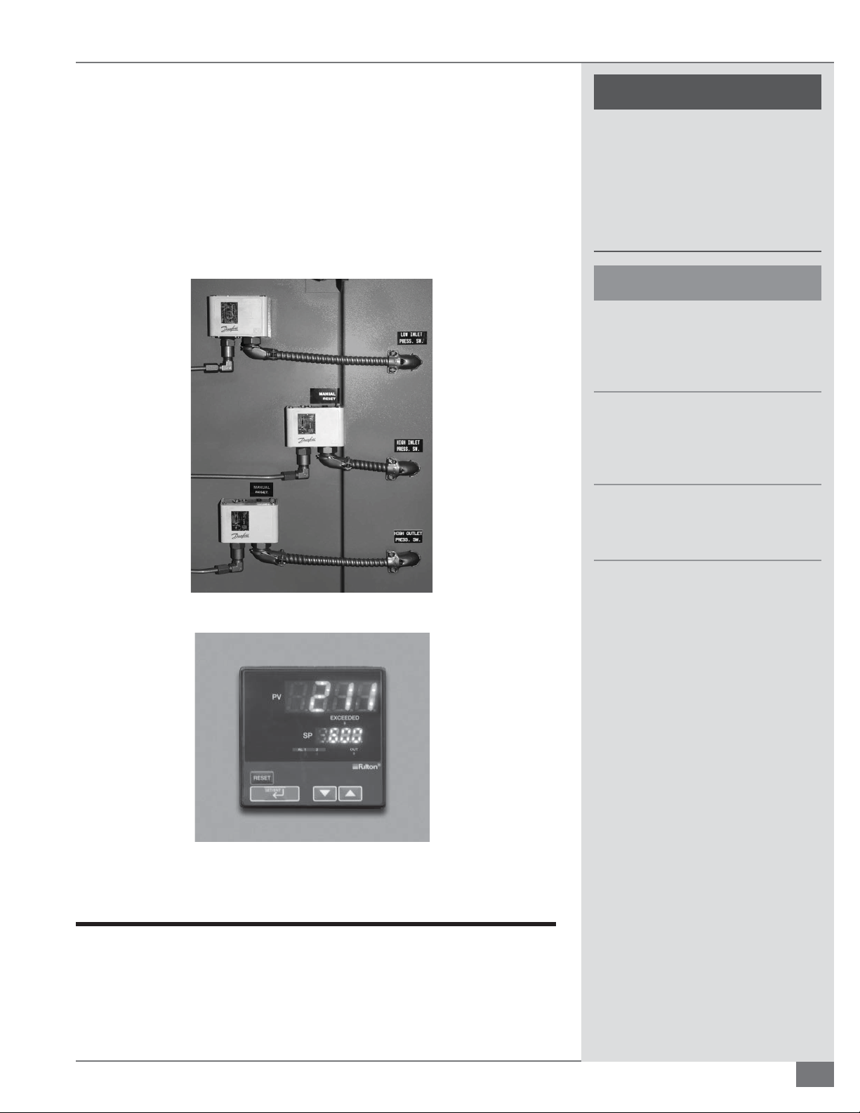
THERMAL FLUID BREAKDOWN PREVENTION
Multiple pressure switches and a di erential pressure switch are used to
prevent this condition from occurring. See Figure 6. These safeties must
not be bypassed at any time.
2-14
Exceeding the maximum operating temperature of the thermal uid will
© The Fulton Companies 2013
Page 21
SECTION 2 FTCS-IOM-2013-1114 INSTALLATION
also result in thermal uid breakdown. Fulton heaters are equipped with a
temperature limit switch (located on the front of the panel box) to prevent
this from occurring.
A high temperature limit switch is an over temperature safety device.
If the high temperature limit shuts down the unit, the manual reset
button on the limit switch must be pressed. The reset button on the
ame programmer must also be pressed to reset the unit before it can be
restarted. See Figure 7. Refer to Maintenance section of this manual for
troubleshooting activities.
FIGURE 6 PRESSURE SWITCHES
! WARNING
All information in this manual is for
reference and guidance purposes,
and does not substitute for required
professional training, conduct,
and strict adherence to applicable
jurisdictional/professional codes and
regulations.
4 CAUTION
The weight of all piping must be
properly supported. Failure to support
piping may result in equipment
damage and/or system leakage.
Piping must take into consideration
potential for damage as a result of
expansion, contraction, vibration, or
other movements.
FIGURE 6 PRESSURE SWITCHES
FIGURE 7 TEMPERATURE LIMIT DISPLAY
Piping Specifi cations
Dirt, water, and/or other debris in the
piping system after welding may result
in equipment failure.
For piping, the basic considerations are: the design temperature, the pressure
retained by the pipe, the uid in the pipe, the load resulting from thermal
expansion or contraction, impact or shock loads imparted such as water hammer,
external loads, wind loads and vibration from equipment.
Questions? Call (315) 298-5121, or visit us online at www.fulton.com
2-15
Page 22
INSTALLATION FTCS-IOM-2013-1114 SECTION 2
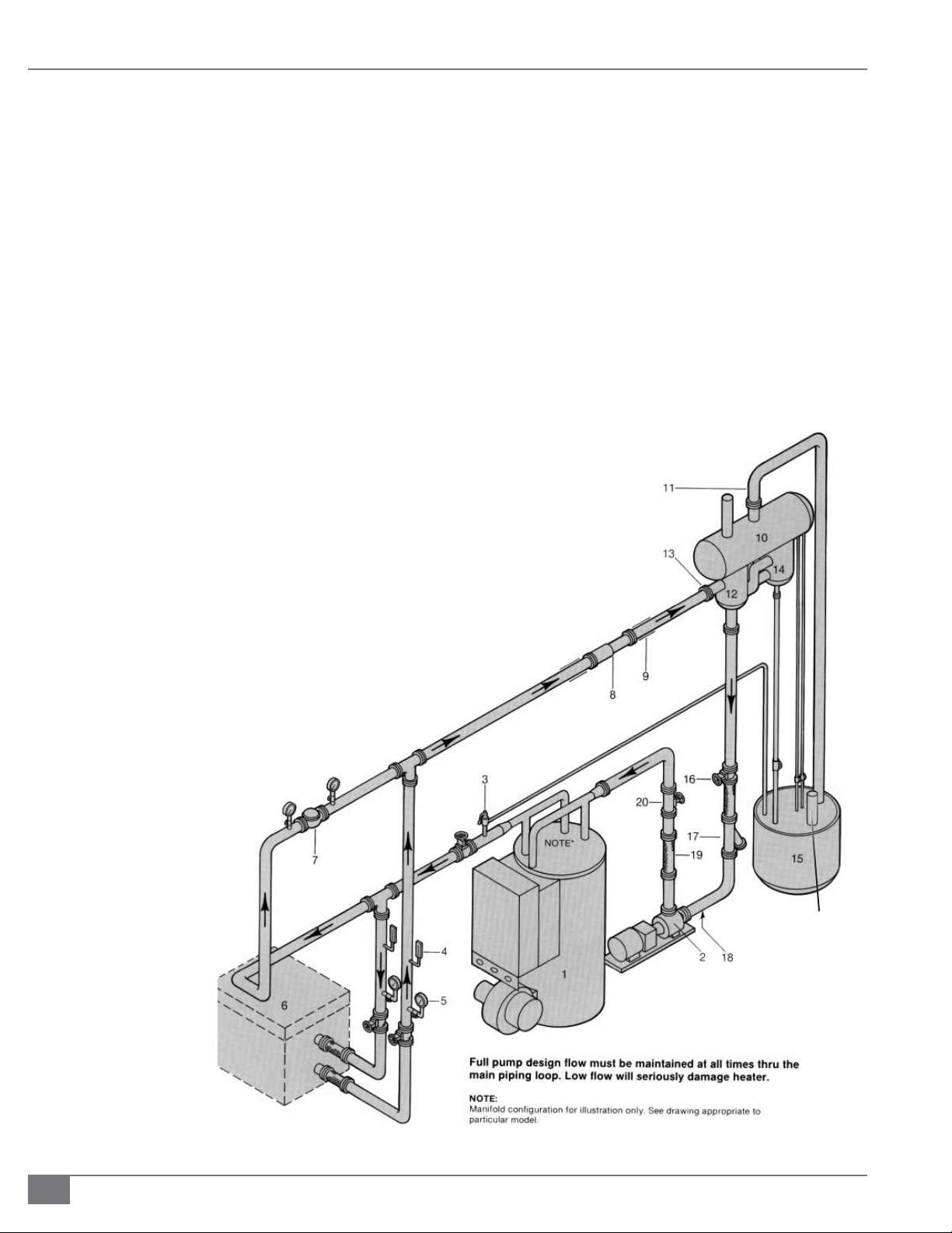
Adhere to the following for piping installation (see Figure 8):
1. Ensure the arrangement of the piping and its
appurtenances takes into consideration the location
of other structures and equipment adjacent to the
piping, which may result in freezing interference and/or
damage as a result of expansion, contraction, vibration,
or other movements.
2. Consider the appropriate location and orientation of
valves necessary for safe operation and isolation of the
piping. Valves are used in piping systems to stop and
start the ow of uids, to regulate ow, to prevent the
back ow, and to relieve excessive pressure build up in
the piping.
Legend
1. Thermal Fluid Heater
2. Thermal Fluid Circulating Pump
3. Safety Relief Valve
4. Thermometer
5. Pressure Gauge
6. Thermal Fluid Heated Equipment
7. Bypass Valve
8. Expansion Joints
9. Anchor and Pipe Guides
10. Expansion Tank
11. Vent Piping
12. Deaerator Tank
13. Deaerator Tank Inlet (must be highest point of piping)
14. Thermal Bu er Tank
15. Catch tank (for drain of pressure relief valve, cold seal, expnasion tank, vent)
16. Valve
17. Strainer
18. 3/4” System Fill Connection
19. Flexible Connection
20. Isolating Valve
21. Manual Low Level Test Line
22. Manual High Level Test Line
23. Bu er Drain
3. Ensure all piping and piping components are suitable
for the design temperatures, pressure and uid used in
the system.
4. Ensure all components exposed to thermal uid ow,
including pipe, valves, and screens, are not copper,
copper alloys, bronze, brass, aluminum, or cast iron.
Cast iron is porous to thermal uids, and copper and
aluminum act as catalysts in the degradation of some
thermal uids. Carbon or stainless steel, or ductile iron,
are recommended.
5. Ensure all pipework is constructed from seamless mild
steel pipe, conforming to ASME SA 106B or SA 53B,
Schedule 40, Schedule 80, or equal, based on design
temperature and pressure of the system.
2-16
Vent to atmosphere
in safe location
FIGURE 8 TYPICAL THERMAL PIPING SCHEMATIC
© The Fulton Companies 2013
Page 23
SECTION 2 FTCS-IOM-2013-1114 INSTALLATION
6. If an isolating valve is completely closed, the pressure
in the system will rise to the deadhead pressure of the
pump. Suitably sized pipe will enable the system to
withstand the total head generated by the circulating
pump, should this occur. In applications where it is
desirable to design to pressures lower than 100 psig,
an alternative safeguard is to install appropriately sized
safety valves.
7. Where secondary circulating pumps are installed,
ensure the system is suitable for the aggregate head,
against a closed valve, of both pumps.
8. During construction of the installation, ensure that no
dirt, water, or residue from welding is left in the system.
9. Consider expansion joints or pipe loops to
accommodate thermal expansion. Design should be
per latest edition of ASHRAE Systems and Equipment
Handbook to prevent detrimental forces and stresses at
connected equipment. Thermal expansion should be
calculated using the maximum possible utilization uid
temperature, regardless of whether the pipe considered
is in the feed or return circuit. Steel pipe will grow
axially and can be expected to expand approximately
1” over 100ft @ 100°F temperature rise (1mm per meter
over 100 C rise).
piping where necessary to prevent undue stress from
being imparted on equipment such as pumps, valves
and the heater. Care should be taken as end reactions
transmitted to rotating equipment, such as pumps,
may deform the equipment. Therefore equipment
manufacturers’ recommendations on allowable forces
and movements should be followed. See Figure 9.
11. Ensure all pipe joints are of either welded or anged
construction. Screwed joints must be avoided where
possible. In no instance should screwed joints be used
in the ow circuit. All anges should be welded to the
pipe and not screwed. Depending on the size, anges
should be 150# or 300# raised face anges, SA105.
12. Ensure heaters that are skid mounted with pumps and
tanks are equipped with a y-strainer, a ex connector
and a valve in the inlet run between the pump and the
combination tank. Piping between the discharge of
the pump and the inlet of the heater will include a ex
connector and a valve.
13. If screwed connections have to be made, e.g., to items
of control equipment, use a thread sealant suitable for
use with uids at elevated temperature. Te on tape,
standard pipe sealant, or hemp and paste are not
acceptable.
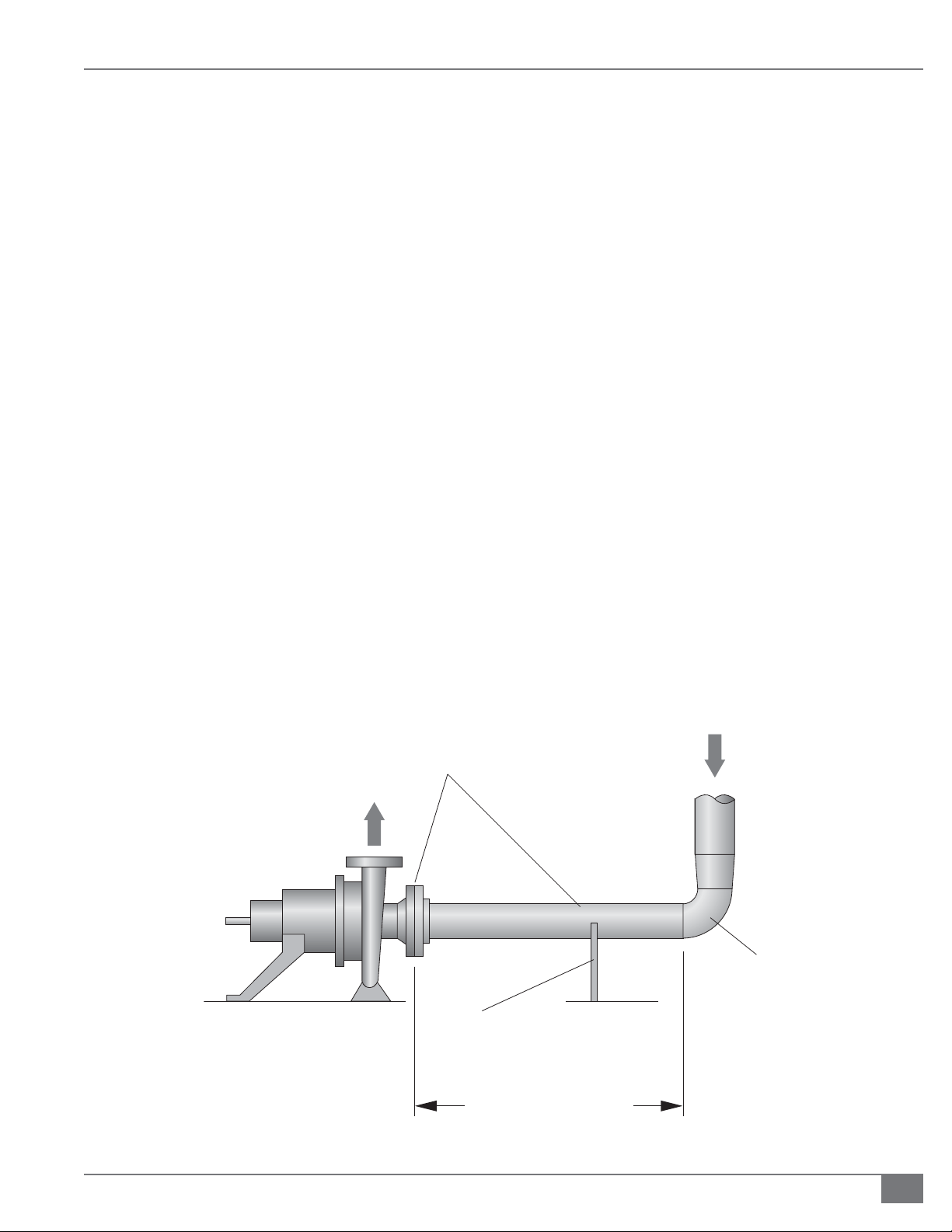
10. Provide properly designed supports and anchors for all
Pipe Must Be
Diameter of
Pump Intake
Pump
14. Cut screw threads carefully and accurately. If possible,
From Outlet of Deaerator
First
Fitting
Pipe Support Must Be
Provided (Not To Be
Welded On Both Ends)
FIGURE 9 TYPICAL PUMP PIPING
Questions? Call (315) 298-5121, or visit us online at www.fulton.com
6 - 10 Pipe Diameters
2-17
Page 24
INSTALLATION FTCS-IOM-2013-1114 SECTION 2
! WARNING
All information in this manual is for
reference and guidance purposes,
and does not substitute for required
professional training, conduct,
and strict adherence to applicable
jurisdictional/professional codes and
regulations.
Non-Fulton product information is for
reference purposes only. No Fulton
document may substitute for full
review of documentation available
from the component manufacturer.
new tools should be used. Threaded connections larger than 1” are not to
be used. It is recommended that GR5 or higher tensile steel bolts be used
for all anged joints.
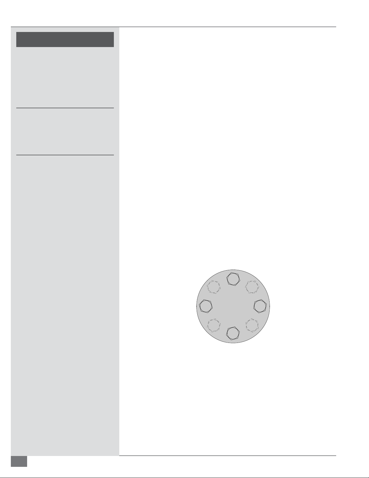
15. Use gaskets to make all anged connections. Gasketing material must be
suitable for use with the pressure, temperatures and uids in the system.
Flexible graphite gaskets are suited for most applications. Recommended
gasket thickness is 1/10 - 1/8 inch. Ensure that all bolts are tightened
evenly and to the torque recommended values provided by the gasket
manufacturer. Refer to Figure 10 and Tables 6-9 for guidelines.
NOTE: Typical gaskets used by Fulton include JM Clipper Elastograph gaskets and
Flexitallic gaskets. Adhere to installation instructions and torque requirements for
these gaskets.
16. Install high point bleeds at all high points in the system piping. 1/2” x 12”
nipples welded in the top of the piping with ball valves and plugs attached
are to be used.
NOTE: It will save a considerable amount of time during the cold ltration if the
system piping is cleaned prior to assembly. The mill scale (the results of oxidation)
on the inside of the piping as well as construction debris can foul the uid and
cause the need for the lters (strainers) to be cleaned more than need be. This can
range from simply using a rag to ordering pickled pipe. (“Pickling” is a process
where the piping is rst soaked in an acid bath, then soaked in a neutralizing bath,
then given a protective oil coating.)
17. Install all pipes with a pitch to facilitate draining and venting.
1
5
3
7
2
FIGURE 10 BOLTING SEQUENCE FOR 4 AND 8 BOLT FLANGES
8
4
6
2-18
© The Fulton Companies 2013
Page 25
SECTION 2 FTCS-IOM-2013-1114 INSTALLATION
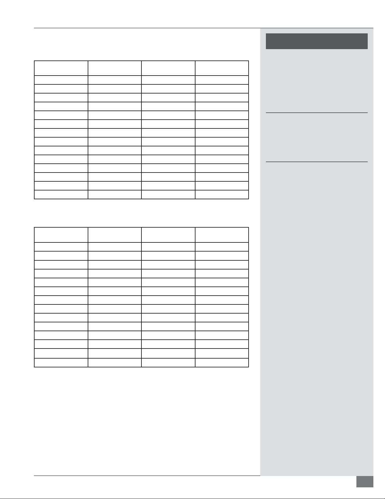
TABLE 6 RECOMMENDED GASKET LOADS FOR FLEXITALLIC SPIRAL WOUND CLASS 150#
GASKETS SAE GRADE 5 BOLTS OR EQUAL
Nominal Flange Size
(inches)
1/2 4 1/2 45
3/4 4 1/2 45
1 4 1/2 45
1 1/4 4 1/2 45
1 1/2 4 1/2 45
2 4 5/8 90
2 1/2 4 5/8 90
3 4 5/8 90
3 1/2 8 5/8 90
4 8 5/8 90
5 8 3/4 150
6 8 3/4 150
8 8 3/4 150
10 12 7/8 240
Number of Bolts Diameter of Bolts
(inches)
Preferred Torque Req.
Per Bolt (ft-lb)
TABLE 7 RECOMMENDED LOADS FOR FLEXITALLIC SPIRAL WOUND CLASS 300# GASKETS
SAE GRADE 5 BOLTS OR EQUAL
! WARNING
All information in this manual is for
reference and guidance purposes,
and does not substitute for required
professional training, conduct,
and strict adherence to applicable
jurisdictional/professional codes and
regulations.
Non-Fulton product information is for
reference purposes only. No Fulton
document may substitute for full
review of documentation available
from the component manufacturer.
Nominal Flange Size
(inches)
1/2 4 1/2 45
3/4 4 5/8 90
1 4 5/8 90
1 1/4 4 5/8 90
1 1/2 4 3/4 150
2 8 5/8 90
2 1/2 8 3/4 150
3 8 3/4 150
3 1/2 8 3/4 150
4 8 3/4 150
5 8 3/4 150
6 12 3/4 150
8 12 7/8 240
10 16 1 368
Number of Bolts Diameter of Bolts
(inches)
Preferred Torque Req.
Per Bolt (ft-lb)
Questions? Call (315) 298-5121, or visit us online at www.fulton.com
2-19
Page 26
INSTALLATION FTCS-IOM-2013-1114 SECTION 2
! WARNING
All information in this manual is for
reference and guidance purposes,
and does not substitute for required
professional training, conduct,
and strict adherence to applicable
jurisdictional/professional codes and
regulations.
Non-Fulton product information is for
reference purposes only. No Fulton
document may substitute for full
review of documentation available
from the component manufacturer.
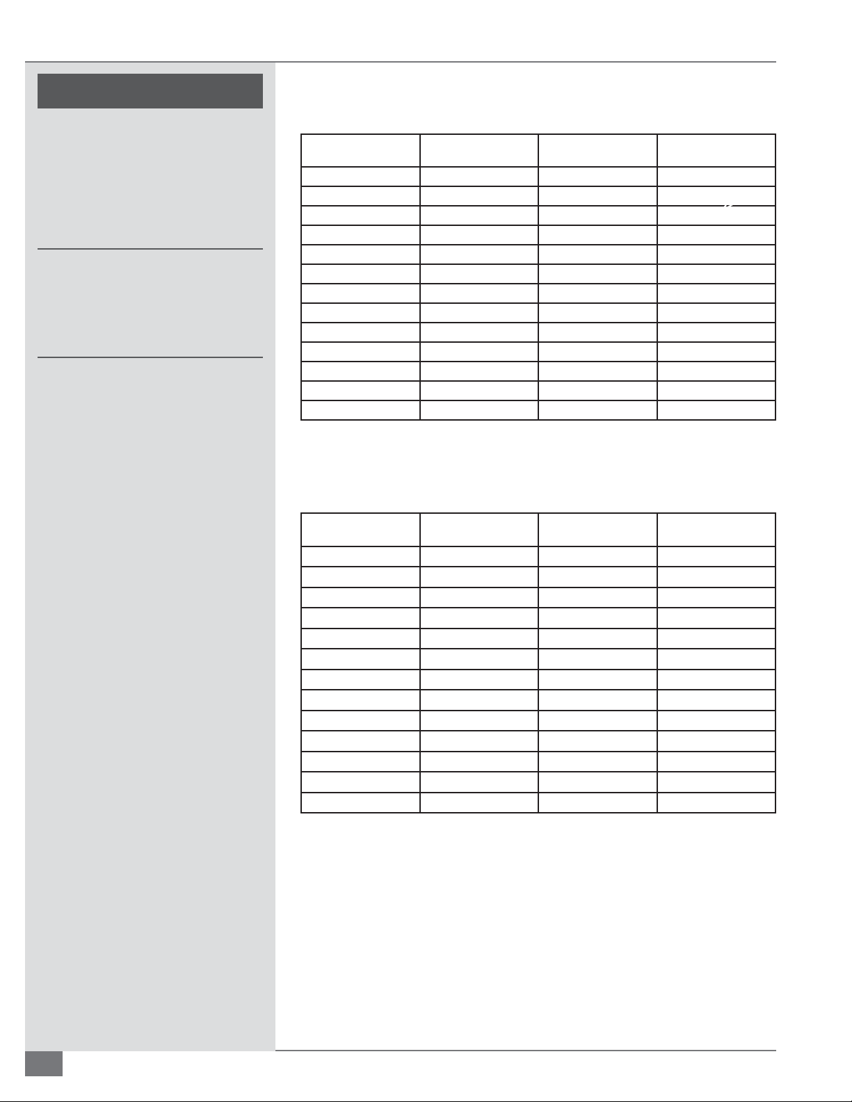
TABLE 8 RECOMMENDED LOADS FOR JM CLIPPER ELASTOGRAPH 150# GASKETS SAE
GRADE 5 BOLTS OR EQUAL
Nominal Flange Size
(inches)
1/2 4 1/2 30
3/4 4 1/2 30
1 4 1/2 30
1 1/4 4 1/2 30
1 1/2 4 1/2 30
2 4 5/8 60
2 1/2 4 5/8 60
3 4 5/8 60
4 8 5/8 60
5 8 3/4 100
6 8 3/4 100
8 8 3/4 100
10 12 7/8 160
Number of Bolts Diameter of Bolts
(inches)
Preferred Torque Req.
Per Bolt (ft-lb)
TABLE 9 RECOMMENDED LOADS FOR JM CLIPPER ELASTOGRAPH 300# GASKETS SAE
GRADE 5 BOLTS OR EQUAL
Nominal Flange Size
(inches)
1/2 4 1/2 30
3/4 4 5/8 60
1 4 5/8 60
1 1/4 4 5/8 60
1 1/2 4 3/4 100
2 8 5/8 60
2 1/2 8 3/4 100
3 8 3/4 100
4 8 3/4 100
5 8 3/4 100
6 12 3/4 160
8 12 7/8 245
10 16 1 160
Number of Bolts Diameter of Bolts
(inches)
Preferred Torque Req.
Per Bolt (ft-lb)
2-20
© The Fulton Companies 2013
Page 27

SECTION 2 FTCS-IOM-2013-1114 INSTALLATION
! WARNING
Insulation
All information in this manual is for
After the appropriate system tests have been satisfactorily completed
(see Testing section of this manual), all hot pipework and vessels must be
adequately insulated with material suited to the temperature and application
to prevent both heat loss and personnel injury.
Adhere to the following for insulation installation:
reference and guidance purposes,
and does not substitute for required
professional training, conduct,
and strict adherence to applicable
jurisdictional/professional codes and
regulations.
1. For inspection and maintenance purposes, leave pumps, anges, valves
and ttings uninsulated but suitably shielded for safety.
2. Insulate the deaerator section of the combination tank.
3. Do not insulate the thermal bu er and expansion sections of the
combination tank. On units operated with inert gas blankets above the
uid in the expansion tank, the entire combination tank, including the
expansion and thermal bu er sections, may be insulated but it is not
necessary.
4. Ensure hot oil pipe insulation is a minimum of 2” (51 mm) thick,
high temperature, laminated, foamglass cellular glass insulation as
manufactured by Pittsburgh Corning Corporation or equal.
5. For heaters equipped with ue gas recirculation (FGR) on the burner, the
ducting must be insulated to prevent personnel injury.
System Interfaces
Proper selection and installation of the components in the hot oil system will
ensure proper and safe operation of the heater.
Heater Connections
Adhere to the following for heater connections:
1. Connect the outlet of the pump directly to the inlet of the heater via
an isolating valve (preferably a throttling valve) and pump exible
connector.
To maintain a reasonable
temperature in the equipment area
and ensure safety to personnel, the
section of the chimney duct within
the building should be insulated.
Due to extremely high operating
temperatures of the thermal uid,
all exposed pipework should be
insulated, and exposed hot anges,
pump, valve, and ttings should be
shielded. Refer to Insulation section of
this manual for details.
No shuto of any kind may be
placed between the safety relief
valve and the equipment, or in the
discharge pipe between such valve
and the atmosphere. Doing so may
cause accidental explosion from
overpressure.
Discharge from safety relief valve
must be con gured so that there
is no danger of scalding personnel
or causing equipment damage.
Provisions must be made to properly
drain safety relief valve discharge
piping.
2. Pipe heater outlets directly to the system via an isolating valve.
3. A safety relief valve may be shipped in the parts box accompanying the
fuel- red heater, and must be installed in the outlet manifold. On all units,
the outlet must be piped to a safe discharge area. The piping from the
outlet of the safety valve must be piped to a catch tank. The discharge
ow must not be restricted, i.e. no valve should be installed. The weight of
the piping must be properly supported in order to prevent damage to the
safety valve. If the valve body becomes warped, leakage may result.
Questions? Call (315) 298-5121, or visit us online at www.fulton.com
Failure to insulate ducting
on equipment with Flue Gas
Recirculation on the burner may
result in personnel injury.
2-21
Page 28
INSTALLATION FTCS-IOM-2013-1114 SECTION 2
Thermal Fluid Circulating Pump
Installing the pump in accordance with the manufacturer’s
speci cations and these instructions will prolong the life
of the pump and contribute signi cantly to the successful
operation of your Fulton heater system. The pump
manufacturer’s installation and operation instructions can be
obtained from the manufacturer.
Adhere to the following for pump installation (see Figure 9):
1. Locate pump adjacent to the heater. Its base must be
rm, level (preferably concrete), and free from vibration.
2. Route pump per the manufacturer’s requirements. It
should be equipped with exible connections at the
suction and discharge sides. The primary function of
these connections are to prevent stresses due to pipe
expansion from being placed on the pump and to
isolate pump vibrations from the pipe work and the
heater. They also allow for expansion and de ection of
the pipe work. These connections should be rated for
high temperature since they are considered part of the
piping system.
3. Connect suction pipe work directly to the deaerator
section via a vertical run with as few elbows as possible.
It should contain the strainer and an isolating valve.
The discharge pipe work must be connected directly to
the heater inlet, and should contain an isolating valve.
See that pipe work connections match up accurately
with pump anges. Refer to the pump manufacturer’s
recommendations for the speci c pump inlet piping
requirements. Typically these requirements are that:
It be a straight run of pipe.
The straight run from the pump inlet to the rst tting,
valve, or ex connector be a minimum of 6-10 pipe
diameters in length.
The pipe used should be the same size as the inlet of
the pump.
The piping in the immediate vicinity of the pump
must not be supported by the pump. The pump is not
designed to bear the weight of the piping, and weight
on any part of the pump will throw it out of alignment.
Proper alignment directly a ects bearing, coupling,
and seal life expectancy. The pump is properly aligned
before it leaves the factory. Because the system expands
in operation, pump must be realigned when the system
is at operating temperature.
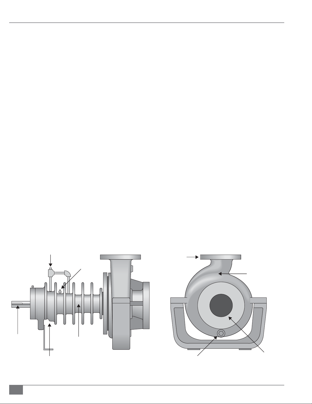
GREASE FITTING
1/4” X 1/8”
KEYWAY
2-22
3/8” NPT BARRIER OIL
FILLMECH. SEAL ONLY
1/8” NPT
3/8” NPT BEARING GREASE
RELIEF AND LIP SEAL
FAILURE DETECTION
DISCHARGE
1/8” NPT VENT
1/2” NPT DISCHARGE
GAUGE CONNECTION
WHEN SPECIFIED
PUMPAGE
LEAK DETECTION
MECH. SEAL ONLY
SUCTION
1/2” NPT CASING DRAIN
WHEN SPECIFIED
FIGURE 11 TYPICAL AIR COOLED PUMP
© The Fulton Companies 2013
Page 29
SECTION 2 FTCS-IOM-2013-1114 INSTALLATION
The coupling alignment of the pump and driver must
be carefully checked for angular and axial alignment.
Check pump manufacturers instructions for these
speci cations. The use of a dial indicator to check the
axial and angular alignment is recommended.
An air cooled pump does not have an oiler. This type
of pump has a sleeve bearing which is, like the seals,
lubricated by thermal uid. An air cooled pump has a
grease nipple located at the drive end of the pump near
the coupling connection. This comes pre-greased, and
should be greased at intervals as recommended by the
manufacturer.
An oiler is shipped with each water colled pump and
should be lled with lubricating oil recommended by
the manufacturer. The suggested lubricant is usually a
SAE-30 non-detergent oil.
Thermal uid is not su cient lubrication for bearings.
All seals on air cooled pumps are lubricated by thermal
uid, therefore the pump must never be run dry, i.e.,
without thermal uid in it.
Filling a pump equipped with either a Grafoil packed
or mechanical seal with thermal uid will ensure
lubrication. However, in order to be certain that all seals
on an air cooled pump are coated with thermal uid,
the pump must be bled.
Grafoil packings require a run-in procedure. Typically,
pumps with these seals are shipped with four or ve
rings installed and several rings loose. These extra rings
must be on hand for the initial run-in procedure. See
manufacturer’s instruction manual for this procedure.
Requirements for Air Cooled Pumps
Adhere to the following (See Figure 11):
1. Allow for free air ow around the entire pump casing at
all times.
2. Maximum room temperature should be 100°F (38°C).
3. In no case should any part of the drive side of the pump
be insulated.
4. Maximum operating temperature for air cooled pumps
varies by manufacturer. Consult instruction manual to
verify.
Requirements for Water Cooled Pumps
Adhere to the following for (See Figure 12):
1. Requirements for water cooled pumps will vary with
manufacturer. Consult manufacturer’s instructions for
ow rate and temperature requirements.
2. Check local codes regarding disposal of hot water.
FIGURE 12 TYPICAL WATER COOLED PUMP
Questions? Call (315) 298-5121, or visit us online at www.fulton.com
2-23
Page 30
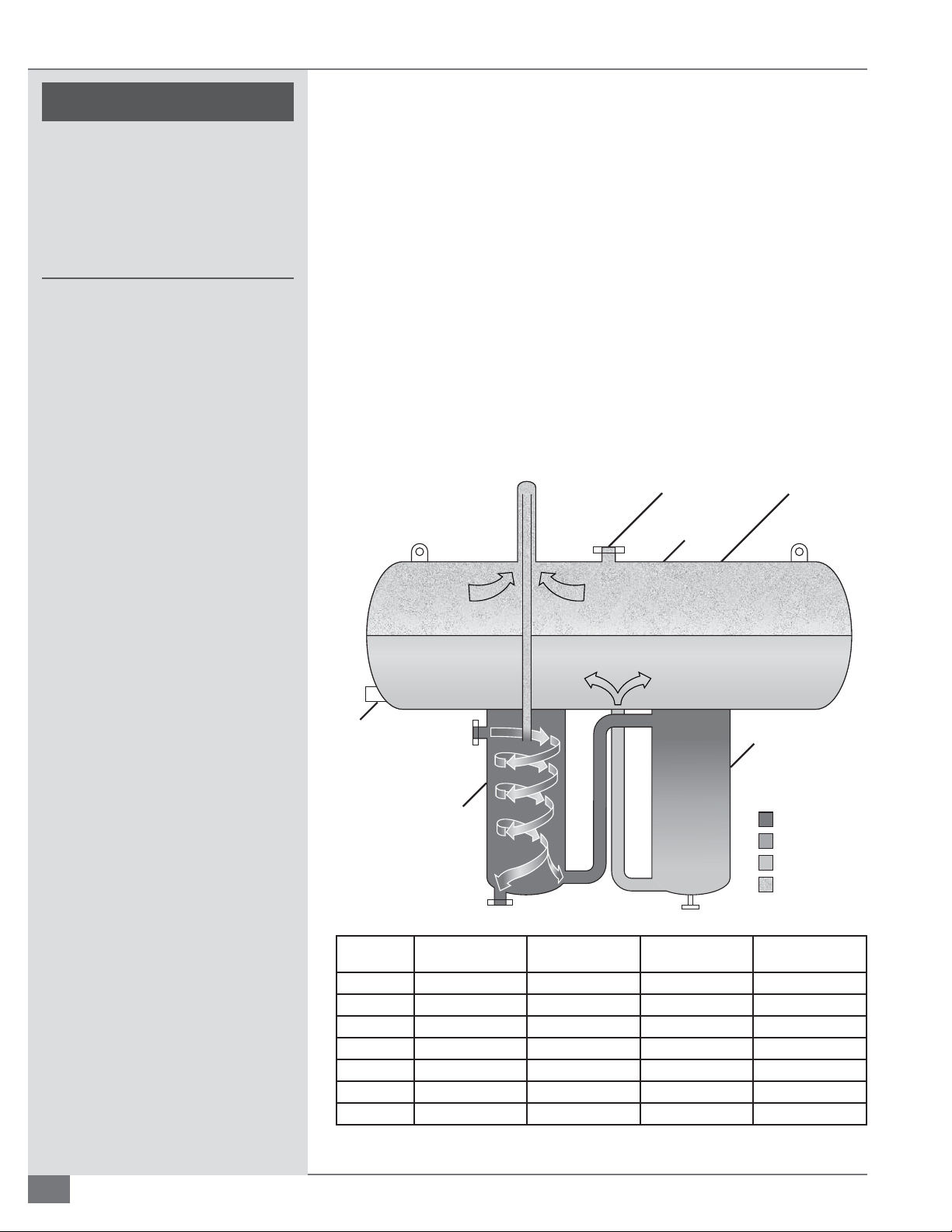
INSTALLATION FTCS-IOM-2013-1114 SECTION 2
! WARNING
All information in this manual is for
reference and guidance purposes,
and does not substitute for required
professional training, conduct,
and strict adherence to applicable
jurisdictional/professional codes and
regulations.
Combination Deaerator/Thermal Buff er/Expansion Tank
Fulton Thermal’s e cient design combines the operation of the expansion,
deaerator, and thermal bu er tanks. Installation is considerably simpli ed by
virtue of this arrangement.
The expansion section is vital to the thermal uid system. From ambient to
operating temperature, the thermal uid in the system will typically expand
in the range of 25% to 50%, and a vessel capable of handling this expansion is
mandatory. The customer should con rm the expansion rate of the chosen uid
and system volume.
At start up, the primary purpose of the deaerator section is to remove all volatiles
from the system to avoid pump cavitation. The deaerator section also allows air
to be vented from the system on a continuous basis during operation to avoid
oxidation of the thermal uid, and removes other volatile particles generated by
the uid itself during system operation. This section of the tank must be insulated.
Vent for Piping
to Safe Catchment
Expansion
Tank
Expansion
Volume
Liquid
Level
Switch
Model Capacity (gallons) Initial Fill (gallons) Available for
FT-200-L 52 25 46 184
FT-500-L 132 40 121 525
FT-1000-L 264 80 232 1000
FT-1500-L 397 90 380 1400
FT-2000-L 528 145 444 1700
FT-3000-L 793 215 717 2600
FT-5000-L 1310 300 1168 4600
Fluid In
Deaerator
Section
Fluid Out
Expansion (gallons)
FIGURE 13 EXPANSION TANK DETAILS
Drain
Thermal
Buffer
Section
Hot Fluid
Medium Fluid
Cool Fluid
Gases (Steam)
Max System Volume
2-24
© The Fulton Companies 2013
Page 31
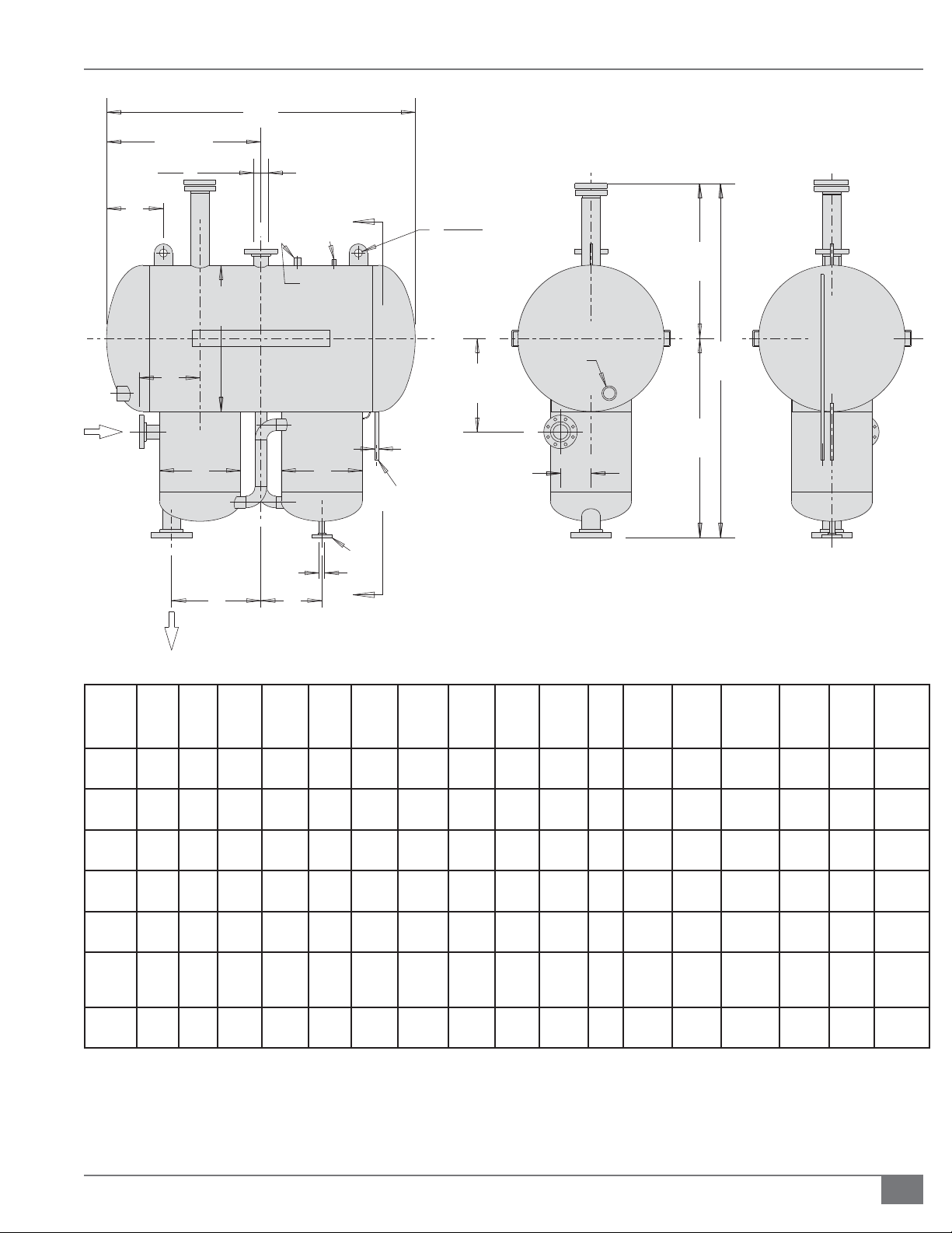
SECTION 2 FTCS-IOM-2013-1114 INSTALLATION
C
1/2C
VENT
(TYP.)
3
(76)
K
N2 REGULATOR
1/2
(13)
2
R
(50.8)
F
P
A
M
SAFETY RELIEF
VALVE CONN.
EXPANSION TANK
LIQUID
LEVEL
LIQUID LEVEL
SWITCH
COUPLING
D
MANUAL
TEST
CONNECTION
L
INLET
DEAERATOR
N
THERMAL
BUFFER
BB
1/2
(13)
J
DRAIN & LIQUID LEVEL
DRAIN
R
E
GH
OUTLET
Model A B C D E F G H J K L M N P CAP Dry
Wt.
FT-
0200-L
FT-
0500-L
FT-
1000-L
FT-
1500-L
FT-
2000-L
FT-
3000-L
FT-
5000-L
20
(510)
26
(660)
36
(915)
36
(915)
42
(1070)
42
(1070)
60
(1524)
12 3/4
(325)
16
(405)
20
(510)
20
(510)
22
(560)
26
(660)
26
(660)
54
(1370)
74
(1880)
76
(1930)
106
(2690)
106
(2690)
140
(3556)
130
(3312)
3/8
60 5/8
(1540)
66 5/8
(1692)
5/8
87
(2226)
87
(2210)
5/8
107
(2734)
115 1/8
(2924)
1/8
132
(3356)
34
(865)
37
(940)
49
(1245)
49
(1245)
62 1/2
(1590)
70
(1778)
77 1/2
(1969)
5/8
26
(676)
29 5/8
(752)
5/8
38
(981)
5/8
38
(981)
45 1/8
(1146)
45 1/8
(1146)
5/8
54
(1387)
16 11/16
(424)
3/4
19
(502)
1/4
22
(565)
3/4
24
(629)
3/16
31
(792)
33 3/16
(843)
32 3/16
(818)
12
(305)
14
(355)
15
(380)
17
(445)
24
(610)
24
(610)
24
(610)
1/2
4
(115)
6 (150) 11
11/16
7
(202)
1/2
8 (203) 14 (355) 24
8 1/2
(216)
9 15/16
(252)
9 3/8
(238)
4 1/4
(108)
(290)
14 (355) 24
15 1/2
(394)
15 1/2
(394)
20
(524)
1/2
5/8
15
(380)
18
(460)
(610)
(610)
28
(710)
28
(710)
37
(940)
15/16
12
(329)
14 15/16
(379)
14
(379)1 (25)
14
(379)1 (25)
14
(379)1 (25)
18
(481)1 (25)
18
(481)1(25)
3/4
(20)
3/4
(20)
15/16
15/16
15/16
15/16
15/16
3/4
(20)
3/4
(20)
1
(25)
1/4
1
(32)
1/2
1
(38)
1 1/2
(38)
1 1/2
(38)
52
(200)
132
(500)
264
(1000)
397
(1500)
528
(2000)
793
(3000)
1321
(5000)
636
(289)
970
(440)
1350
(612)
1710
(776)
2550
(1134)
3200
(1451)
5300
(1637)
Max
Full
Wt.
1314
(596)
2450
(1111)
4380
(1987)
5875
(2667)
8230
(3733)
11,610
(5265)
17,370
(7895)
Inlet and outlet dimensions vary with installation. All dimensions are approximate. Speci cations are subject to change without notice. Dimensions
are in inches (mm). Capacities are in gallons (liters). Weights are in pounds (kg).
FIGURE 14 COMBINATION/EXPANSION/DEAERATOR THERMAL BUFFER TANK
Questions? Call (315) 298-5121, or visit us online at www.fulton.com
2-25
Page 32

INSTALLATION FTCS-IOM-2013-1114 SECTION 2
! WARNING
All information in this manual is for
reference and guidance purposes,
and does not substitute for required
professional training, conduct,
and strict adherence to applicable
jurisdictional/professional codes and
regulations.
High temperature thermal uid,
steam, and combustible vapors
may be vented through the vent
connection on the combination
deaerator/thermal bu er/expansion
tank.
4 CAUTION
Non-code tanks cannot be pressurized
over 15 psig.
A system of interconnecting pipe work in the thermal bu er tank section
prevents the movement of any oil that has not cooled su ciently into the
expansion section. This avoids contact of very high thermal uid temperature
with oxygen contained in the atmosphere, which causes uid breakdown. DO
NOT insulate this section.
Sizing The Expansion Tank For The System
Expansion tank capacity is the total volume of the tank. It is necessary to have
some air space available at the top of the tank to avoid spillage or over ow. At
initial ll (for system volume calculations) the deaerator and cold seal sections
must be lled completely and the expansion section must be lled to a level of 4
inches (102 mm) to “make” the liquid level switch.
The volume between the initial ll level and the safe “full” level is the amount
available for expansion. That volume is used to decide which tank is suitable for
the system expansion.
SIZING EXAMPLE
A system contains 175 gallons, including the heater, but not the tank. You select
the FT-200-L, so you add 25 gallons to 175 for a total of 200 gallons.
You look up the expansion rate for the thermal uid. (Assuming it is 25%), 200
gal. x 1.25 = 250 gallons, 250-200 = 50 gallon expansion.
The FT-200-L has only 46 gallons available for expansion, so the correct selection
is the FT-500-L.
Adhere to the following for installation:
1. Install tank in accordance with Fulton Thermal Corporation’s speci cations.
2. Unless the system is pressurized, the inlet to the deaerator section must be
higher than or equal to the highest point in the system to prevent pockets
of air from collecting in system piping.
3. Take into account the head required at the circulation pump suction inlet to
avoid the possibility of pump cavitation.
4. In systems operating close to maximum uid temperature, ensure the tank
is elevated enough, possibly well above the highest point in the system, to
prevent pump cavitation by increasing the static head. An inert pressurizing
blanket may be considered as an alternative. See Pressurized Systems
section of this manual.
5. Provide supports for tank mounting. These should be suited for supporting
the tank by the side rails. The eyelets tted to the tank are for lifting only.
2-26
© The Fulton Companies 2013
Page 33

SECTION 2 FTCS-IOM-2013-1114 INSTALLATION
Pressurized Systems
Nitrogen pressurization may be used if the total system content is very large, or
in a system operating near or above the vapor pressure of the uid employed, or
if the inlet of the DA tank is not the highest point in the piping system, or at any
time to further protect the uid from oxidation.
In conjunction with this system, adhere to the following:
1. An automatic venting device must be tted to the system expansion tank.
Consult Fulton Thermal Corporation for further details.
2. The location for the liquid level switch (Figure 15) is a 2-1/2” NPT connection
on the same end of the tank as the inlet. The liquid level switch is supplied
and shipped with the unit, and must be installed by the customer and then
wired to the control panel.
3. If the tank is located outdoors, nitrogen is required.
! WARNING
All information in this manual is for
reference and guidance purposes,
and does not substitute for required
professional training, conduct,
and strict adherence to applicable
jurisdictional/professional codes and
regulations.
Failure to ensure vent connections
terminate into a well-ventilated
area with catch tank may create an
environmental hazard.
FIGURE 15 LIQUID LEVEL SWITCH LOCATION
Questions? Call (315) 298-5121, or visit us online at www.fulton.com
2-27
Page 34

INSTALLATION FTCS-IOM-2013-1114 SECTION 2
! WARNING
All information in this manual is for
reference and guidance purposes,
and does not substitute for required
professional training, conduct,
and strict adherence to applicable
jurisdictional/professional codes and
regulations.
Once the system has been lled,
any modi cation to the tank or
connected piping requires purging
of the work area to prevent ignition
of potentially ammable vapors.
Consult factory prior to beginning
work. Consult Material Safety Data
Sheet (MSDS) for your thermal uid
for ammability limits.
4 CAUTION
If the deaerator/thermal bu er/
expansion tank is located outdoors, a
nitrogen blanket is required.
Vent Connections
Adhere to the following for vent connections:
1. Make vent connection in a manner that will prevent penetration of water
or foreign bodies into the tank. This connection must always terminate
in a safe, well ventilated area and has to be free of obstruction, open to
atmosphere, and arranged in such a manner that, in the event of discharge
from the system, thermal uid could drain into a catch tank without
danger to personnel or property.
2. Make the vent run the same size as the tank outlet. It should run pitch
down from the outlet of the tank to the catch tank.
3. If nitrogen is used on the system, the vent can be reduced to 2” (51 mm)
and should be piped with a positive closing valve at the catch tank.
4. Ensure the connection between the tank outlet and the horizontal pump
inlet is as close to a vertical drop as possible. It should have the minimum
bends and length of pipe.
5. Ensure the inlet to the deaerator is higher than or equal to the highest
point in the system, or a pressurized system must be used.
6. Field-install the liquid level switch (supplied and shipped with the unit).
This must be wired to the control panel.
7. Ensure test connections are accurate. The high and low level test
connections are 1/2” NPT, and are located on the end of the tank opposite
the inlet. The low level is on the center line of the expansion tank, the high
level is next to it, slightly o center. The high level rises up from the bottom
of the tank and ends 4” (102 mm) below the top; the low level rises 2” (51
mm) from the bottom of the tank.
2-28
8. Both the high and low level connections should be piped to a safe
catchment. Valves should be installed in these lines at the catch tank.
Installation of the valves should be accomplished in such a manner that
any ow will be visible when the valves are open.
9. Flow from the high level test connection indicates a tank that is too full; no
ow from the low level test connection indicates too little uid.
10. There is a 300 #, raised face, anged drain on the bottom of the thermal
bu er section, for the purpose of draining the tank when necessary. This
should be piped with a valve in the line, to a safe catchment. The valve
speci cations outlined above apply to this valve as well.
11. An inspection opening is located at the highest point on the tank. Access
to this port is recommended but not required.
12. Refer to the maintenance schedule for recommendations on draining the
bu er tank. For positioning of all connections on tank, see Figure 14.
© The Fulton Companies 2013
Page 35

SECTION 2 FTCS-IOM-2013-1114 INSTALLATION
Catch Tank
Adhere to the following for the catch tank:
1. Ensure the heater safety relief valve outlet and connections on the DA tank
are piped to a safe catch tank. The catch tank must be appropriately sized
based on the system volume and con guration.
2. Under normal operating conditions, the catch tank should be empty. Fluid
that is expelled into the tank should not be reintroduced into the system.
3. Ensure the vent from the catch tank is located and installed in such a
manner as to protect personnel and property from discharge of steam,
water, and thermal uid. Vent outlet should be positioned in a safe location
outside of heater room.
Drain/Fill Connection
The system is usually lled from the lowest point, with the aid of a pump. On skidmounted units, a drain and ll connection is provided in the inlet piping to the
pump. See Figure 16.
! WARNING
All information in this manual is for
reference and guidance purposes,
and does not substitute for required
professional training, conduct,
and strict adherence to applicable
jurisdictional/professional codes and
regulations.
Failure to properly locate and
install vent connections may cause
personnel and property damage.
FIGURE 16 DRAIN AND FILL CONNECTION
Pressure Gauges
The range in which readings are expected to fall should comprise mid-scale on
the pressure gauge chosen (See Figure 17). Pressure gauges must be able to
FIGURE 17 GAUGES
Questions? Call (315) 298-5121, or visit us online at www.fulton.com
2-29
Page 36

INSTALLATION FTCS-IOM-2013-1114 SECTION 2
! WARNING
All information in this manual is for
reference and guidance purposes,
and does not substitute for required
professional training, conduct,
and strict adherence to applicable
jurisdictional/professional codes and
regulations.
withstand overpressure equal to the rating of the safety relief valves (normally
100 psig).
Thermometers
Thermometers should read up to 650°F (343°C). For systems with higher
operating temperatures, thermometers should be selected accordingly.
Valves
Adhere to the following for valve installation:
1. Use vent and drain valves that normally are 1/2” or 3/4” with internal seals
made from materials suited to use with thermal uids. They may be of the
screw type if installed on stalks not less than 12” (30.5 cm) long.
2. Use gasketing material speci cally suited to the task.
3. Fit drain valves at all low points in the pipework system and ventilating
valves at all high points in the installation. Valves must be tted with either
the conventional packed stu ng box seal or a bellows seal as required.
4. Where the stu ng box is speci ed, it should be as deep as possible and
packed with Grafoil packing or equal. The valves should have a backseating
to allow re-packing without draining the system.
5. In all units, install a “Y” type strainer in the uid return line, between the
deaerator tank and the circulating pump. This strainer is provided on
all skid-mounted units. Valves must be provided (unless the heater has
been skid-mounted with the tank) so that the strainer can be isolated for
cleaning of the element. The strainer element should be 60 mesh and must
remain in place during normal operation of the system.
6. Check the pump suction pressure periodically, under similar operating
conditions. A vacuum reading on the suction gauge indicates that the
screen must be cleaned. For isolating purposes, globe, wedge, gate, ball, or
other shut-o valves should be used. When there is a likelihood that some
manual balancing will be required, a ball or globe valve should be used.
7. Ensure manual control and isolating valves are of the anged or weld type,
manufactured from cast or forged steel or ductile iron, with internals and
gland seals made from materials suitable for use with high temperature
uids.
8. When ordering valves, obtain the maximum possible service temperature
and type of uid. A partial list of manufacturers known to market valves of
acceptable quality follows:
Stockham Valves and Fittings Company
2-30
Velan
Vogt Machine Company
Worcester Valve Company
© The Fulton Companies 2013
Page 37

SECTION 2 FTCS-IOM-2013-1114 INSTALLATION
Automatic Fluid Control Valves
Because of the widely varied processes in which Fulton Thermal Fluid Heaters
are used, it is not possible to provide speci c rules for the selection of automatic
uid control valves. Generally, these valves must satisfy the speci c materials and
construction requirements.
The type of operation and design of porting are governed by the degree of
control required as well as the particular application.
By-Pass Valves
When process ow requirements do not match heater ow requirements, a bypass valve must be installed. If the process ow will vary with the system load, a
suitable bypass system can be recommended by Fulton Thermal Corporation.
Assembly of Fulton Multi-Skid Engineered Systems
Adhere to the following for multi-skid engineered systems:
1. Refer to the Fulton mechanical/electrical drawings during assembly.
2. Ensure that equipment orientation allows for operation interface and
maintenance.
! WARNING
All information in this manual is for
reference and guidance purposes,
and does not substitute for required
professional training, conduct,
and strict adherence to applicable
jurisdictional/professional codes and
regulations.
For reasons of safety, the hot exhaust
gas duct and chimney must be
insulated or shielded within the
locality of the heater in compliance
with local codes and regulations.
4 CAUTION
The stack arrangement and draft
conditions should be in accordance
with the information in this manual for
proper performance of the equipment.
3. Align the skids as shown on the drawings ensuring that skid fasteners (skid
joint angles) are matched. The skid joint angles are a matched set and the
edges of the fasteners should be exactly aligned.
NOTE: Do not bolt the skids to the housekeeping pad/ oor until all of the piping
has been reassembled and tightened.
4. Ensure the skids are level and at before fastening the skids together with
the supplied bolts. The skids should be leveled front to back, side to side
and corner to corner. Failure to properly level the skids will result in piping
misalignment. A level or laser level should be used to verify skid alignment
(when a standard level is used, the length should be appropriate for the
skid). If assembling multi-component support stands, attach sections
using the supplied bolts through the tank frame mounting plates. These
should be hand tight until all of the piping is assembled. Note: skids are
leveled at the factory using a laser level.
5. Connect the piping between the skids by matching the union connections
and/or ange stamps and tightening. Refer to the mechanical drawing
as necessary to con rm location of spool pieces etc. as the ange stamps
are shown on the drawing in hexagonal callouts. The ange stamps
should matched and aligned (the ange stamps should be directly across
from one another. Rotating a ange will result in piping misalignment).
Bolts should be hand tight until all of the piping is assembled. Refer to
the appropriate instructions to tighten the anges to the required torque
speci cations. Support pipe runs as required.
6. Ensure that a low point drain is installed in the piping.
Questions? Call (315) 298-5121, or visit us online at www.fulton.com
2-31
Page 38

INSTALLATION FTCS-IOM-2013-1114 SECTION 2
! WARNING
All information in this manual is for
reference and guidance purposes,
and does not substitute for required
professional training, conduct,
and strict adherence to applicable
jurisdictional/professional codes and
regulations.
Do not attempt to start the
equipment for any testing prior
to lling and purging the vessel.
A dry re will seriously damage
the equipment and may result in
property damage or personnel injury
and is not covered by warranty. In
case of a dry ring event, shut o
the fuel supply and allow the vessel
to cool to room temperature before
uid is reintroduced to the pressure
vessel.
Failure to insulate ducting
on equipment with Flue Gas
Recirculation on the burner may
result in personnel injury.
4 CAUTION
7. Connect the conduit runs between the skids and tighten conduit
connectors.
8. Locate the supplied wiring for the equipment and pull wiring through
the appropriate conduit runs. Electrical wires are labeled for easy landing.
Connect all wiring per the Fulton supplied electrical drawings.
9. If a header is supplied, mount the header as shown in the mechanical
drawing.
NOTE: For piping supplied in sections, make up and connect hand tight until all
sections are in place to ensure sections align properly. Sections are match marked
for reassembly.
10. Tighten all connections.
11. Pneumatically test the piping (at 15 psig maximum) prior to lling the
systems.
12. Check bolts and connections for tightness after the rst heat up cycle.
Retorquing may be required.
Stack and Flue
An appropriately sized stack should be connected to the ue gas outlet at the
heater. The proper ue size and draft control is most important for proper burner
operation. The ue must be as large or larger than the outlet on the vessel.
Avoid ue piping and elbows by placing the equipment as close as possible to
the chimney.
Avoid ue corrosion and other negative
impacts ensuring properly-sized stack
and ue.
In order to meet warranty conditions,
ensure appropriate tests and
operational safety activities are
performed.
Unless specially ltered, compressed air
will introduce moisture to the system.
Dry air or nitrogen is recommended.
Adhere to the following for stack and ue installation (see Figure 18):
1. Ensure the stack is the same diameter as the ue gas outlet for an FT0080C, and at least one size larger for the coil design models FT-0120C and
larger.
2. Ensure the stack rises continuously to the connection at the chimney and
contains no more than two bends at 45 degree angles or less. If required,
as a result of space limitations, one 90 degree elbow (or tee) can be tted
at the back of the vessel.
3. Ensure 2 feet (0.6 m) of straight, horizontal ue before any change in
direction, tting or draft regulator. This is to prevent potential pilot or
main ame failures due to back pressure build up during ignition. Any
alternative stack arrangement must supply negative 0.02 to 0.04”wc.
4. Ensure the run in the total distance of stack ducting, as measured in a
straight line from the outlet of the heater to the outlet of the stack, does
not exceed 70% of the rise. With the exception of the duct run previously
described, horizontal sections of ducting must be avoided and should not
exceed 4 feet (1.2 m) total. See Figure 18.
5. Ensure the stack, chimney, and any components associated with the stack,
such as heat reclaimers or assist fans, are constructed from material that is
2-32
© The Fulton Companies 2013
Page 39

SECTION 2 FTCS-IOM-2013-1114 INSTALLATION
rated for a 1200°F (649°C) operating temperature.
6. Ensure the stack and chimney material complies with all
applicable codes.
7. Make adequate provisions for the support of the
weight of the chimney and stack to avoid having a load
imparted to the outlet connection of the equipment.
8. Ensure the draft, when ring, is negative and constant.
A reading of -0.02 to -0.04”wc when the unit and stack
Install
Appropriate
Weather
Cap
Support As
Necessary
are cold usually indicates su cient draft. When the unit
is running and the stack is hot, the draft should read 0.04
to 0.08 “wc negative.
9. The installation of a draft regulator by the client/
contractor should be considered at all installations,
and installed if necessary. This will help to maintain the
required draft. The placement of the draft regulator
should be as shown in Figure 19.
10. Insulate the section of the chimney duct within
Minimum
6' Above
Any Structure
Within 30'
Roof
Cleanout
Door
This Distance
Must Not
Exceed 70%
Of Total Rise
Expansion Joints
As Required
Stagger
Entrances
Draft Regulator Draft Regulator
60°
Horizontal
Run 2'
(45° Min.)
Cleanout
Door
Horizontal
Run 2'
Total
Rise
AA
A-A
3'
3'
30°
Max
Baffle
Cleanout
Door
FIGURE 18 TYPICAL STACK AND FLUE INSTALLATION
Questions? Call (315) 298-5121, or visit us online at www.fulton.com
2-33
Page 40

INSTALLATION FTCS-IOM-2013-1114 SECTION 2
2'2'
X = 3 TO 5 PIPE DIAMETERS ON EACH SIDE OF DAMPER
Wrong Wrong Wrong
Right
X
X
Right:
Minimum
1 Pipe
Diameter
X
X
Poor
Wrong:
Less Than
1 Pipe
Diameter
FIGURE 19 BAROMETRIC DAMPER INSTALLATION
the building. For heaters equipped with Flue Gas
Recirculation (FGR), ducting must be insulated to
prevent personnel injury.
11. Concentration levels of only a few ppm of chlorine
containing compounds in combustion air can produce
serious corrosion of the ue over long periods of time.
High chlorine containing compounds such as carbon
tetrachloride or perchloroethylene would be prime
suspects.
Testing
Upon completion of the installation, perform the following
testing:
1. A pneumatic test of thermal uid piping not exceeding
15 psig.
2. Soap tests at all welds and joints to ensure that the
system is free from leaks.
Wrong
NOTE: Under no circumstances should the system be lled
with water. Make sure that the air supply is as free from
moisture as possible.
3. Boil-out. The time needed for adequate boilout directly
corresponds to the volume of the system and the
amount of moisture and debris in the system. Boilout
typically takes anywhere from one to three days to
complete. Pressure testing on the system should be
done by means of an inert gas such as nitrogen or by an
air compressor producing dry air (air with a dewpoint of
50°F [10°C] or less). Never perform a hydrostatic test on
the system. The boilout procedure is described in the
Operation section of this manual.
4. The most satisfactory method of testing is to introduce
bottled nitrogen through a pressure control valve.
Check pressure ratings on all equipment in the system
to ensure that it is capable of withstanding the pressure
involved.
2-34
© The Fulton Companies 2013
Page 41

OPERATION
INTRODUCTION
1
INSTALLATION
2
OPERATION
MAINTENANCE
PARTS & WARRANTY
3
4
5
Questions? Call (315) 298-5121, or visit us online at www.fulton.com
3-1
Page 42

OPERATION FTCS-IOM-2013-1114 SECTION 3
! WARNING
All information in this manual is for
reference and guidance purposes,
and does not substitute for required
professional training, conduct,
and strict adherence to applicable
jurisdictional/professional codes and
regulations.
Do not operate, or allow others
to operate, service or repair this
equipment unless you (they) fully
understand all applicable sections
of this manual and are quali ed to
operate/maintain the equipment.
Defective or improperly installed
equipment is hazardous. Do not
operate equipment which is defective
or improperly installed.
Never leave an opened manual air
vent unattended. In the event an
opened vent is left unattended, water
or uid damage could occur. The
exception to this warning is a feed
water deaerator manual vent cracked
open may be left unattended.
Start-Up Preparation & Installation Review
NOTE: System start-up MUST be performed by a Fulton factory technician.
Warranty will not be valid if system start-up is not performed by a Fulton
factory technician.
Review the installation section of this manual carefully. Con rm accordance with
the Installation guidelines, including:
1. You have read and followed all safety information.
2. The equipment area is in conformance with established boiler room
requirements. Review national and local codes.
3. There is total absence of water in pipework and uid. To help the system,
open all drains; blow dry air or nitrogen if available into a high point bleed
through a pressure regulating valve.
4. There are no obstructions left in the uid circuit from pressure leak testing
such as blanking plates in anged joints.
5. Pipework is free to expand naturally when hot. Open all valves to user
circuits including air bleed valves at high points and drains at low points in
the piping system, and the liquid level test connections in the expansion
section of the combination tank.
6. Heater is located with the proper clearances as shown in Installation
section of this manual.
Defective equipment can injure you
or others. Do not operate equipment
which is defective or has missing parts.
Make sure all repairs or maintenance
procedures are completed before
using the equipment. Do not attempt
repairs or any other maintenance
work you do not understand.
4 CAUTION
Installation in accordance with the
guidelines within the manual should
be fully completed before performing
the initial start-up; and start-up must
be complete prior to putting the unit
into service. Starting a unit without
the proper piping, venting or electrical
systems can be dangerous and may void
the product warranty.
“Factory Trained Personnel” refers to
someone who has attended a Fulton
Service School speci cally for the
equipment covered in this manual.
7. Relief valves have been properly piped to a safe catchment.
8. Flue gas from the heater is properly vented.
9. Combustion air openings are not obstructed in any way and have
adequate capacity.
10. There are no ammable liquids, materials or hazardous fumes present in
the environment.
11. Nothing was damaged or knocked loose during shipment and installation.
Inspect the main gas train and trim assembly to be sure they were not
damaged during shipment or installation.
12. Local authorities where approval for start-up is required have been
noti ed. In some localities, nal inspection of services may be required.
13. Installation checklist is complete.
3-2
© The Fulton Companies 2013
Page 43

SECTION 3 FTCS-IOM-2013-1114 OPERATION
Fill the System
The viscosity of thermal uid is generally very high (500 cS) at ambient
temperature. Below 50°F (10°C) some uids become very thick. Fluid should be
in a pumpable liquid form prior to lling the system. Refer to the thermal uid
manufacturer’s recommendations.
Adhere to the following when lling the system:
1. Refer to Figure 17 for the drain and ll connection.
1. Filling must be carried out from the lowest point in the system in order to
prevent air pockets from forming.
2. A drain and ll point (generally a 3/4” threaded coupling) is provided on
the inlet to the pump suction on skid-mounted units.
3. Typically a portable, high velocity pump, such as the type used for
chemical transfer, is appropriate for lling the system. Where only one or
two drums of uid are required, a handheld pump may be practical.
Filling Procedure for Systems Open to Atmosphere
Adhere to the following:
1. Follow the instructions in Fill The System section of this manual.
2. Check to see that the liquid level switch operates freely. To con rm
operation of the liquid level switch, manually trip the liquid level switch.
Unit should shut down; pump will stop.
3. Fill the system slowly, closing all opened bleed and drain valves as uid
reaches them.
! WARNING
Pressurizing a drum to force uid into
the system is not recommended. The
drum may explode, creating a hazard
to personnel and equipment.
During operation, any leaks are
usually detected by a small amount
of vapor. Leaks should be attended
to as soon as possible because under
certain circumstances, such as
saturated insulation, thermal uid can
ignite when exposed to air and heat.
4 CAUTION
Do not use this equipment if any part
has been under water (or subjected to
heavy rains/water if the equipment does
not have NEMA 4 wiring, controls and
instrumentation). Immediately call a
quali ed service technician to inspect
the equipment and to replace any
part of the control system and/or gas
control(s) which have been under water.
Commissioning/Start up by a nonFulton authorized person will void the
product warranty.
4. When the uid reaches and ows from the expansion tank low level
manual test connection, begin slowing down the lling process.
5. Close the low level connection and continue to ll until the liquid level
switch closes. After uid appears in the low level connection, only a small
amount of additional uid should be required.
6. If uid is observed coming from the expansion section high level manual
test connection, drain uid from the tank until the level is between the
liquid level switch and the high level connection.
7. Filling is complete when the uid has reached the lowest level in the
expansion tank required to actuate the liquid level switch.
8. As oil reaches a vent, close it. After all vents have been closed, and you
believe the system to be full, stop lling. Start the circulating pump as
described in Initial Start-Up: Cold Circulation section of this manual.
Leave the ll equipment connected as cleaning the strainer may create the
need for more oil in the system.
9. Verify to see that the liquid level switch operates freely. To con rm
operation of the liquid level switch, manually trip the liquid level switch.
Unit should shut down; pump will stop.
Please read these instructions and
post in an appropriate place near the
equipment. Maintain in good legible
condition.
The system pump is not to be used to ll
the system.
A pump that has been used for water
or a di erent thermal system should
not be used prior to extensive cleaning.
Thermal uid may be damaged by
contact with moisutre of other uids.
Questions? Call (315) 298-5121, or visit us online at www.fulton.com
3-3
Page 44

OPERATION FTCS-IOM-2013-1114 SECTION 3
! WARNING
All information in this manual is for
reference and guidance purposes,
and does not substitute for required
professional training, conduct,
and strict adherence to applicable
jurisdictional/professional codes and
regulations.
Crystalline silica may be present
in components of this equipment.
Exposure to crystalline silica may
pose signi cant health hazards,
including but not limited to eye and
respiratory system damage. Per
the Centers for Disease Control and
Prevention (CDC) and Occupational
Safety and Health Administration
(OSHA), appropriate personal
protective equipment must be worn
to minimize exposure to hazardous
substances. Refer to most current
guidelines o ered by the CDC and
OSHA for more information, including
personal protective equipment
recommendations.
Use extreme caution when opening
circulating pump plug if system
temperature is elevated.
Filling Procedure for Systems Equipped with Inert Blankets
Adhere to the following:
1. Follow the instructions in Fill The System section of this manual.
2. Inspect the system to be sure all valves are open and all drains are closed.
3. Open all high point air vents.
4. Do not pressurize the system with nitrogen at this point.
5. Inspect the liquid level switch (Figure 16) and be sure the switch is
functioning properly.
6. Begin lling the system.
7. Fill the system until the liquid level switch indicates there is oil in the
expansion tank.
8. Pressurize the system slightly with nitrogen. Leave the high point vent
connections open, as the nitrogen should be isolated from the vents by the
oil in the system. The pressure required in the system at this point is only
2-3 psi. If too much pressure is applied, the nitrogen will bubble through
the oil and vent to atmosphere. If this happens, reduce the pressure.
9. Continue lling the system. If liquid level switch is made, be sure to
observe the high point vents as oil is now entering the elevated portion
of the pipe work. As oil reaches the vent, close it. After all vents have
been closed, and you believe the system to be full, stop lling. Start the
circulating pump as described in Initial Start-Up: Cold Circulation
section of this manual. Leave the ll equipment connected as cleaning the
strainer may create the need for more oil in the system.
Non-Fulton product information is for
reference purposes only. No Fulton
document may substitute for full
review of documentation available
from the component manufacturer.
If a re does occur, extinguish using
, foam or dry chemical. DO NOT
CO
2
USE WATER.
10. Determine the nal nitrogen pressure by measuring the di erence
between the D.A. Tank inlet and the highest point in the system. Divide
that number by 2.31 (this will indicate the nitrogen pressure the system
should be set for).
11. If the tank is located outdoors and the inlet to the tank is the highest point
in the system, then 1-2 psig of nitrogen is su cient.
12. Adjustment can be made via the regulator mounted on top of the D.A.
tank.
NOTE: If you are using a uid above its boiling point, the system must be
pressurized to overcome the vapor pressure of the uid. Consult the factory
for assistance.
3-4
© The Fulton Companies 2013
Page 45

SECTION 3 FTCS-IOM-2013-1114 OPERATION
Circulating Pump
Adhere to the following:
1. Read manufacturer’s instruction manual thoroughly. If the pump is
supplied by Fulton Thermal Corporation, manufacturer’s literature is
included with this manual.
2. Never run the pump without uid in the casing. For pumps equipped
with mechanical or air-cooled seals, air must be bled out of the stu ng
box area to ensure that thermal uid has lubricated all seal and bearing
areas. Operation of the pump even a short time without bleeding rst will
damage the pump.
3. Use the thermal uid as a barrier uid. Remove the 3/8” plug at the barrier
uid ll port. Fill the cavity with thermal uid until it comes out of the
over ow tube. Replace the 3/8” plug.
Pump With Mechanical/Air Cooled Seal
Adhere to the following:
1. Open the air bleed connection located directly over the pump shaft.
Replace plug when a steady stream of thermal uid, free of entrained air,
ows from the port.
! WARNING
All information in this manual is for
reference and guidance purposes,
and does not substitute for required
professional training, conduct,
and strict adherence to applicable
jurisdictional/professional codes and
regulations.
4 CAUTION
Operation of the circulating pump
for any amount of time without rst
bleeding will result in equipment
damage.
If uid temperature exceeds 150°F
during start-up and no ow has been
induced, discontinue start-up and
contact Fulton Service Department.
Failure to do so may cause equipment
damage.
2. If ow has not started after two to ve minutes, remove the coupling
guard and rotate the pump shaft by hand in the proper direction. This
should help move the cold viscous uid through close tolerance seal areas.
Replace plug when ow is steady.
3. If this fails to induce ow, introduce uid through the bleed port and rotate
the shaft by hand to work the uid around the seal area. Continue to add
uid and rotate the shaft until no more uid can be added.
4. Replace the plug and run pump for ve to ten seconds. Stop the pump,
remove the plug and wait for ow to start. If after two minutes ow has
not started, add more uid as described above and run the pump for ve
minutes.
5. Constantly check the bearing area (located immediately behind the casing)
for overheating. Remove the plug and check for ow.
6. If ow has not started at this point, the uid may be too viscous to move
through the seal area. Start the system normally by selecting heat on the
control panel, and raise the temperature 50°F. Continue to raise the system
temperature by 50°F increments. Keep checking the pump until ow starts.
NOTE: If at 150°F (65.5°C) there is still no uid ow, discontinue start-up
and contact Fulton Service Department immediately.
7. The pump should not be subjected to thermal or pressure shock. The
thermal uid should, therefore, be allowed to ow into the casing slowly.
Questions? Call (315) 298-5121, or visit us online at www.fulton.com
3-5
Page 46

OPERATION FTCS-IOM-2013-1114 SECTION 3
! WARNING
All information in this manual is for
reference and guidance purposes,
and does not substitute for required
professional training, conduct,
and strict adherence to applicable
jurisdictional/professional codes and
regulations.
Never attempt to operate equipment
that has failed to pass all safety
checks.
This heater is equipped with an
ignition device which automatically
lights the burner. Do not try to light
burner by hand.
Operating this equipment beyond
its design limits can damage the
equipment and can be dangerous.
Do not operate the equipment
outside of its limits. Do not try to
upgrade the equipment performance
through unapproved modi cations.
Unapproved modi cations may
cause injury, equipment damage, and
will void the warranty.
Before commissioning the unit, verify
with proper authorities that gas lines
have been purged.
Check daily that the equipment area
is free and clear of any combustible
materials, including ammable
vapors and liquids.
8. Check eld work and make sure that all connections have been made in the
proper places. Check electrical connections to the motor.
9. Rotate the pump shaft by hand to be sure there is no binding or rubbing
within the pump or driver. Correct any problems immediately.
10. Check to see that pump is properly aligned while cold. The pump is
properly aligned before it leaves the factory. Because the system expands
in operation, the pump must be realigned when the system is at operating
temperature.
11. Carefully check the coupling alignment of the pump and driver for angular
and axial alignment. Check pump manufacturers instructions for these
speci cations. The use of a dial indicator to check the axial and angular
alignment is recommended.
12. Realign at operating temperature, if necessary.
13. Make sure that the pump is properly greased or oiled.
Pump with Packed Seal
Adhere to the following: Make certain that the gland is nger tight before lling
the system.
Start-Up Service
If start-up service has been included in the order, the factory should be contacted
after the installation has been successfully completed and approved by the client’s
representative or engineers. Where possible, contact the factory at least three
weeks before a Fulton service engineer is required on site.
Consider the following in preparation for your on-site visit:
1. All procedures covered in manual sections Start-Up Preparation and Fill the
System, including installation review, air testing of piping, pump alignment
(where applicable), and lling the system must be completed before the
service person’s arrival.
2. Depending on the size of the system and the amount of service time
contracted, start-up service includes ring the heater, checking, verifying and
adjusting all safety settings.
3-6
3. Careful preparation can expedite the commissioning of your heater. Most
delays can be avoided by following the instructions in this manual. Failure
to complete required procedures properly can result in the need for further
service time, at extra cost to the customer.
4. Service people will not commence start-up if there are obvious system
de ciencies. However, start-up service in no way constitutes a system design
check or approval of the installation.
5. In addition to commissioning the heater, the service person will also
familiarize heater room personnel with the operation of all Fulton equipment.
Personnel must be quali ed to understand the basic operation and function
of controls.
© The Fulton Companies 2013
Page 47

SECTION 3 FTCS-IOM-2013-1114 OPERATION
Initial Start-Up
These instructions are for use when the unit is being started up for the rst
time, or after prolonged shutdown. They are to be used in conjunction with the
speci c procedure information in manual section Routine Operation.
Cold Circulation
1. Turn on the main power switches.
2. Check for proper uid level in the expansion section of tank. See Figure 13
and 14.
3. A centrifugal pump cannot be operated with the discharge valve closed
without heating up dangerously.
4. The pump should be started with the suction valve full open and the
discharge valve open a slight amount.
5. Check pump rotation. Operating the pump in reverse rotation may cause
extensive damage.
6. Turn the three position switch located on the front of the panel box door
to “Pump”.
7. Jog the green pump motor starting button and observe the direction of
rotation. Rotation should be in the direction of the arrow shown on pump
casing. If the rotation direction is incorrect, turn the three position switch
back to “O ” immediately. Change the wiring connections and recheck.
8. Check for proper alignment. Realign, at temperature.
! WARNING
All information in this manual is for
reference and guidance purposes,
and does not substitute for required
professional training, conduct,
and strict adherence to applicable
jurisdictional/professional codes and
regulations.
4 CAUTION
Do not use this equipment if any part
has been under water (or subjected to
heavy rains/water if the equipment
does not have NEMA 4 wiring, controls
and instrumentation). Immediately
call a quali ed service technician to
inspect the equipment and to replace
any part of the control system and/or
gas control(s) which have been under
water.
A temperature exceeding 120°F** in
the boiler room may cause premature
failure of electrical components.
Provisions should be made to maintain
an ambient temperature of 120°F** or
less (the panel box interior should not
exceed 125°F**).
9. With the control switch set to “Pump” push and hold the pump start
button, check all manual resets on pressuretrols. The circulating pump will
run, but the burner will not re.
10. If the pump stops when the button is released, check for proper ow in the
system, and review settings of high and low uid pressure switches and
di erential pressure switch. Check liquid level switch.
11. Check that all pressure gauge readings remain stable. Refer to Figure
18. Pressure exceeding 100 PSIG or identical readings at inlet and outlet
gauges indicate a closed valve.
12. If an extremely high vacuum (i.e.15” Hg or more) is indicated on the
compound gauge, the valve between the circulating pump and the
combination tank may have been left closed. In this case, little or no
pressure will be indicated by other gauges.
13. Check all piping, connections and users for leaks. Repair any leaks
immediately.
**Pumps, PLC or ModSync panels
may require lower ambient
temperatures or additional cooling.
Questions? Call (315) 298-5121, or visit us online at www.fulton.com
3-7
Page 48

OPERATION FTCS-IOM-2013-1114 SECTION 3
! WARNING
Before commissioning the equipment,
verify with authorized personnel that
the gas lines have been purged.
Never attempt to operate a heater that
has failed to pass all the safety checks.
After checking controls by manual
adjustment, make sure they are
always reset to their proper settings.
Contact your Fulton dealer before
modifying the equipment.
If any “Manual Reset” limit device trips
DO NOT reset without determining
and correcting the cause. (Manual
Reset Limits may include: ame
safeguard, high or low gas pressure,
high temperature limit, high pressure
limit)
Never tamper with low water (liquid
level) cuto sensors or circuitry.
Filtering the System
1. Initially, readings on the gauge will indicate zero or slightly positive
pressure. During the rst few moments of ow, this reading will go towards
vacuum, indicating that the strainer is becoming plugged.
2. Typically, a reading of 3” Hg or greater vacuum on the pump suction gauge
indicates that the strainer must be cleaned. The strainer screen should be
back ushed or pulled, cleaned and replaced.
3. In some cases, a positive pressure can be measured at the pump suction
gauge (due to the use of a nitrogen blanket or large positive head). This
should be noted and if the reading decreases by several inches or pressure,
check the strainer to ensure it clean.
4. Strainers should be cleaned by means of compressed air. A rag will merely
force the smaller particles into the mesh of the strainer. It is recommended
to place a lint free rag in the center of the strainer and blow air from the
outside, trapping the debris in the rag.
5. Allow the pump to run again for several minutes and repeat the ltering
process until pump suction pressure remains steady after cleaning. The
amount of time which must be allotted for ltering varies with the system.
6. When the system is initially brought up to temperature, additional pipe
scale and welding slag will loosen and enter the uid stream. This will be
trapped in the strainer causing vacuum at the pump suction.
WHAT TO DO IF YOU SMELL GAS :
Do not use matches, candles, ame
or other sources of ignition to check
for gas leaks. Do not try to light the
appliance. Do not touch any electrical
switch; do not use any phone in your
building. Immediately call your gas
supplier from a neighbor’s phone.
Follow the gas supplier’s instructions.
If you cannot reach your gas supplier,
call the re department.
If excessive amounts of thermal uid
are to be vented from the system,
additional thermal uid may be
required in the system. Contact Fulton
for further information.
Flash steam may be generated at any
point up to the operating temperature.
Watch for gauge uctuations.
If uid or piping is added to the system,
the boil out procedure is required, as
water may have been introduced to
the system.
Boilout
1. Ensure adequate ventilation.
2. Check for correct fuel feed. All air must be eliminated from fuel lines, gas
piping, preheaters, etc. by approved methods.
NOTE: As the system is being boiled out, the piping must be checked for leaks
as the temperature of the thermal uid is increased. If a leak is detected, refer
to Thermal Fluids at Elevated Temperatures section in Installation section of
this manual.
3. Open all manual valves in the fuel oil supply line. Do not run the fuel pump
dry or without fuel lines connected to fuel source. Do not allow the fuel oil
pump to pull a vacuum.
4. Check safeties.
5. Disable N2 blanket if equipped and open vent line on DA tank.
6. Set control switch to “Heat”. The burner will begin the call for heat if oil
temperature is below setpoint.
7. With burner ring and pump running, keep checking the gauges indicating
pump and circuit pressures. Make sure they remain stable.
8. In case of pressure uctuations, stop the burner, but allow the pump to
3-8
© The Fulton Companies 2013
Page 49

SECTION 3 FTCS-IOM-2013-1114 OPERATION
continue to circulate uid.
9. When pressures have stabilized, start burner again.
10. Continue in this manner up to the maximum operating temperature.
Throughout the initial warm-up, the expansion tank and its over ow pipe
must be watched to detect the formation of steam, indicating the presence of
water. If this occurs, burner should be shut down.
11. If steam is forcing thermal uid out of the expansion tank vent, turn the
heater o , but leave the pump on. This is to circulate the hot uid through the
piping without ushing the steam too quickly. Once steam and thermal uid
stop leaving the expansion tank unit, the heater can be turned on. Increase
the temperature very slowly to prevent uid from being forced out of the
tank.
12. Continue bringing unit up to temperature slowly, with a temperature rise not
exceeding 100°F (38°C) per hour. Do not exceed speci ed maximum outlet
temperature. In the absence of speci c information, consult the factory before
proceeding.
13. Once up to temperature, check the uid level in the expansion section by
opening the high level manual test connection. If a permanent ow of uid
results when this valve is opened, and if all previous precautions have been
followed, the expansion tank is too small for the capacity of the uid in the
installation. A larger tank must be installed.
14. After fty hours of operation at operating temperature, check all anges and
connections for tightness.
Combustion
Before ring the heater familiarize yourself on the use of the controls, lighting,
and shutdown procedures.
! WARNING
All information in this manual is for
reference and guidance purposes,
and does not substitute for required
professional training, conduct,
and strict adherence to applicable
jurisdictional/professional codes and
regulations.
A quali ed installer, service agency
or the gas supplier must perform
installation and service on the fuel
delivery system.
During system boilout, it is imperative
that all system legs or paths are open
to ensure ow throughout the system.
Never open a cool or unheated user
leg of a system when the rest of the
system is above 210°F ( 99°C).
Do not attempt to start the
equipment for any testing prior
to lling and purging the vessel.
A dry re will seriously damage
the equipment and may result in
property damage or personnel injury
and is not covered by warranty. In
case of a dry ring event, shut o
the fuel supply and allow the vessel
to cool to room temperature before
uid is reintroduced to the pressure
vessel.
SEQUENCE OF OPERATION FOR GAS FIRED BURNERS
The burner is of forced design. The sequence of operation is as follows:
1. The ame programmer opens the main gas valve once stable pilot ame is
established.
2. Pressure regulators on both the pilot and main gas supply, supply pressure to
the proper level.
NOTE: Note the maximum inlet pressure rating of each regulator and supply
a step-down regulator if required.
3. Combustion air is delivered by a centrifugal blower fan. An air switch monitors
the pressure and is part of the ame programmer safety interlock circuit.
4. The ame programmer monitors the safe operation of the burner. Functions
include pre-purge of the combustion chamber, provision of ignition via the
ignition transformer and electrode, opening the pilot gas valve, monitoring
the pilot ame signal via the ame sensor, opening main gas valves and
Questions? Call (315) 298-5121, or visit us online at www.fulton.com
When opening any drains on the
equipment or piping system, steps
should be taken to avoid scalding/
burning of personnel due to hot
uids. Whenever possible, the system
should be cooled prior to opening any
drains.
Use only your hand to turn valve
handles. Never use tools. If the
handle will not turn by hand, don’t try
to repair. Forced or attempted repair
may result in re or explosion.
3-9
Page 50

OPERATION FTCS-IOM-2013-1114 SECTION 3
! WARNING
All information in this manual is for
reference and guidance purposes,
and does not substitute for required
professional training, conduct,
and strict adherence to applicable
jurisdictional/professional codes and
regulations.
Should overheating occur or the gas
supply fails to shut o , manually shut
o the gas supply external to the
equipment .
providing post-purge of the combustion chamber.
5. The ame is monitored by a ame sensor. In the event of insu cient,
unstable, or non existent pilot or main ame, the ame sensor will cause a
safety lockout of the ame programmer. Safety lockout can also be caused if
the ame sensor is improperly positioned or grounded. After fault has been
corrected, reset by pressing the reset button on the casing of the burner
control box.
SEQUENCE OF OPERATION FOR ON/OFF BURNER
The sequence of operation for the on/o burner is as follows:
1. Beginning with power on, limit switch closed, fuel valves closed, and
temperature controller calling for heat, the ame programmer starts the
cycle and the blower motor starts prepurge.
2. The air proving switch must be closed now. Air dampers remain in
maximum position.
3. (Gas Pilot) Provided all safety interlocks are proven, ignition and pilot are
energized and a timed trial for pilot ignition begins. After the pilot ame is
proven, the main fuel valve is energized. Ignition is turned o when ame
is registered and the main gas valves open.
4. (Spark Ignition) At the end of purge time, provided all safety interlocks
are proven, the spark is on and oil valves are opened. When the ame is
proven, the spark is shut o .
5. When the uid temperature reaches the o setting (typically the setpoint
plus 2 to 5 degrees) of the operating temperature controller, all fuel valves
are closed.
The burner motor stops and the entire system is ready for restart on demand.
MODULATING BURNER
The function of the ame programmer must be greatly extended in a modulated
system. Along with limit controls, operating controls and interlock devices, the
programmer automatically controls the operation of the burner, blower motor,
ignition, main fuel valves and modulating motor (or servo motors).
The sequence of operation is as follows:
1. Beginning with power on, limit switch closed, fuel valves closed, and
modulating limit controller closed and calling for heat, the ame programmer
begins its cycle and the blower motor starts prepurge. The modulating circuit
closes, driving the air dampers to maximum for prepurge.
2. The air ow proving switch must be closed now. After timed prepurge, the
modulating motor (servo motor) drives the air damper to its low re position.
All start interlocks must be proven or the ame programmer will lockout.
3-10
3. (Units with Gas Pilot) Ignition and pilot are energized and a timed trial for
pilot ignition begins. After the pilot ame is proven, ignition turns o and the
main fuel valve is energized. Pilot fuel is turned o and the modulating motor
© The Fulton Companies 2013
Page 51

SECTION 3 FTCS-IOM-2013-1114 OPERATION
(servo motor) is released to automatic.
4. (Units with Spark Ignition) The spark and oil valves are energized and a
timed trial for ignition begins. With the ame proven, the control advances
through its main light o sequence, and the ignition shuts o . At this time,
with the ame proven, the modulating motor (servo motor) is released to
automatic.
5. When the modulating motor (servo motor) is released to automatic,
it receives its signal from the modulating temperature controller. The
modulating motor (servo motor) then drives the modulating fuel valve and
air damper in proportion to the heat demand.
6. During the initial call for heat, the modulating fuel valve and air damper will
drive to their full- re position. As the temperature set point is approached,
the modulating motor (servo motor) will continue to reduce the input until
low- re position is reached. Input automatically increases and decreases
according to load demand.
7. When the uid temperature reaches the set point of the temperature
controller or of the optional operating limit controller, all fuel valves will
close and the ame programmer will advance to the post purge cycle.
When the postpurge cycle begins, the modulating motor will be in the low
re position. At the end of postpurge, the burner motor stops and the entire
system is ready for restart on demand.
! WARNING
All information in this manual is for
reference and guidance purposes,
and does not substitute for required
professional training, conduct,
and strict adherence to applicable
jurisdictional/professional codes and
regulations.
Non-Fulton product information is for
reference purposes only. No Fulton
document may substitute for full
review of documentation available
from the component manufacturer.
4 CAUTION
Unburned oil, unlike gas, does not leave
the combustion chamber during purge.
OIL FIRED BURNER
The following refers to the design and operation of the on/o burner utilizing
fuel oil which requires no preheating. This burner is of high pressure, mechanical
atomization design.
The sequence of operation is as follows:
1. An oil pump is used to obtain necessary atomizing pressure before the fuel
oil reaches the nozzle. The fuel oil is divided into ne particles in the nozzle
and imparted with a rotating motion before escaping from the nozzle as a
cone of nely atomized oil.
2. Combustion air is supplied by a centrifugal fan. A damper provides
throttling of the inlet opening. The air from the fan reaches the burner
head after going through a turbulator, accomplishing correct distribution
and mixture of air and atomized fuel oil.
3. An electric spark between two electrodes provides ignition of the
atomized mixture, except where code requires a gas pilot. This spark is
produced by a high voltage transformer.
4. The ame programmer circuit controls normal operation of the burner.
The sequence includes purging of the combustion area for a set period,
ignition and opening of magnetic valves on the oil circuit; post-purge of
combustion area and return to re-start position.
5. A scanner mounted on the burner casing and facing the light of the ame
monitors the ame.
Questions? Call (315) 298-5121, or visit us online at www.fulton.com
3-11
Page 52

OPERATION FTCS-IOM-2013-1114 SECTION 3
! WARNING
All information in this manual is for
reference and guidance purposes,
and does not substitute for required
professional training, conduct,
and strict adherence to applicable
jurisdictional/professional codes and
regulations.
Non-Fulton product information is for
reference purposes only. No Fulton
document may substitute for full
review of documentation available
from the component manufacturer.
6. Safety lock out occurs within a preset minimum time in the event of
insu cient, unstable or non-existent ame. After fault has been corrected,
reset programmer by depressing the reset button on the casing of the
burner control box.
7. Proper fuel pressure at the burner nozzle is essential. The correct ring rate
is obtained by setting the fuel oil pump to give the design pressure for
each unit. This is done at the factory. Pressure is measured by connecting
a 0-400 PSI (0-25 bar) test pressure gauge to the gauge connection on the
fuel pump. The fuel pressure gauge indicates the pressure of the fuel at the
burner nozzle.
8. Typical pressures range between 160-350 PSI (12-22 bar). Note the correct
setting upon commissioning. Modulating units should have a second
pressure gauge monitoring the pressure in the return pipe from the burner.
This gauge will indicate the variation of oil ow caused by modulation of
the burner. Gauge readings should be recorded at start-up and checked
periodically.
DUAL FUEL BURNER CHANGING FUEL
The following instructions apply only to units supplied with dual fuel burners.
These procedures should be performed only when the uid is cold, unless
su cient safeguards are provided to prevent contact with hot uid piping in the
vicinity of the burner.
1. Set the fuel switch to “O ” and the heat selector switch to either “Pump” or
“O .”
Gas to Oil
1. Turn o the manual gas cocks in the gas train.
2. Remove the gas nozzle ori ce assembly from the burner.
3. Install the oil nozzle assembly (see Figure 20) and attach the oil whips to
the assembly.
4. Open all oil manual shuto valves.
5. Set the fuel selector switch to the proper fuel. Restart unit normally
Oil to Gas
1. Turn o all oil manual shuto valves.
2. Detach the oil whips and remove the oil nozzle assembly.
3. Install the gas nozzle ori ce assembly (see Figure 21) and open the gas
cocks in the gas train.
4. Reset the hi/low gas pressure switch.
3-12
5. Refer to Figure 22 for complete dual fuel assembly.
6. Set the fuel selector switch to the proper fuel. Restart unit normally.
© The Fulton Companies 2013
Page 53

SECTION 3 FTCS-IOM-2013-1114 OPERATION
! WARNING
All information in this manual is for
reference and guidance purposes,
and does not substitute for required
professional training, conduct,
and strict adherence to applicable
jurisdictional/professional codes and
regulations.
Non-Fulton product information is for
reference purposes only. No Fulton
document may substitute for full
review of documentation available
from the component manufacturer.
4 CAUTION
Do NOT leave unit unattended in
Manual Operation, in this mode the
LMV51 will ignore its internal Set Point.
FIGURE 20
OIL NOZZLE DUAL FUEL BURNER
MODELS FT0400C THROUGH FT1400C
FIGURE 22 COMPLETE DUAL FUEL ASSEMBLY
FIGURE 21
GAS NOZZLE WITH ORIFICE
DUAL FUEL BURNER
MODELS FT0400C THROUGH FT1400C
Questions? Call (315) 298-5121, or visit us online at www.fulton.com
3-13
Page 54

OPERATION FTCS-IOM-2013-1114 SECTION 3
! WARNING
All information in this manual is for
reference and guidance purposes,
and does not substitute for required
professional training, conduct,
and strict adherence to applicable
jurisdictional/professional codes and
regulations.
Non-Fulton product information is for
reference purposes only. No Fulton
document may substitute for full
review of documentation available
from the component manufacturer.
Flame Programmers
Siemens Linkageless Modulation, LMV 51
NOTE: Refer to cut sheets for any non-Siemens programmers.
SETTING PILOT
1. Verify the main burner switch is in the OFF position.
2. Supply power to the heater. The AZL will display “system test” and then
move to the main menu.
3. Select PWLogin, press Enter. Select AccessServ. Press Enter. (This type
of step will be shown as PWLogin > AccessServ for the remainder of this
section. Enter the service passwords using the arrow key. The password is
case sensitive. The case of a letter can be changed by pressing the other
arrow key. (For example, if you used the right arrow key to get to the
letter A, press the left arrow key to get a). After you have pressed Enter on
the last character of the password, press Enter once more to accept the
password. If you do not have the password, contact your Fulton Authorized
Representative to perform the changes. Service=NB# or OEM=AAAA (Enter
after each A).
4. Select Params&Display. Press Enter. Select Ratio Control. Press Enter.
Select ProgramStop. Press Enter. Change the Program Stop to 44
Interv1 by using the arrow keys. Con rm the change by pressing Enter.
This will set the burner management system to a ‘pilot hold’ setting.
5. Verify that the current value “curr” changes to 44 Interv 1.
6. The full listing of program stops are:
» 24: Air damper in the prepurge position
» 32: Traveling to the FGR position
» 36: Ignition position (before pilot ignition)
» 44: Ignition position (after pilot ignition)
» 52: Ignition position (after main burner ignition)
» 72: Air damper in the postpurge position
» 76: Traveling to the FGR position
7. Press Escape 4 times to get back to the main menu.
8. Under ManualOperation > Setload, change the load to 0% by using the
arrow keys. Press Enter and verify the 0% has been acknowledged in the
“curr” eld.
3-14
9. Press Escape once to get back to the ManualOperation menu.
© The Fulton Companies 2013
Page 55

SECTION 3 FTCS-IOM-2013-1114 OPERATION
10. Under Auto/Manual/O , change the operation to Burner On by using the
arrow keys. Press enter and verify that “Burner On” is acknowledged in the
current eld.
11. Press Escape twice to get back to the main menu.
12. Turn the main burner switch Local or On position.
13. Increase the set point. Under operation-Heater set point go to setpoint
W1 using the arrow key then press Enter. Change the set point under new,
using the arrows and press Enter. The new set point should appear under
actual and displayed in degrees.
14. After several seconds the burner control will start its pre-ignition phase and
the blower will start.
15. You can observe the status of the burner by going to the main menu (by
pressing Escape) then selecting Operational Stat > Normal Operation.
16. The unit will purge then drive to the ignition position and the pilot should
light.
17. The burner control will stay at this pilot hold stage so you can inspect and
adjust the pilot as needed.
! WARNING
Non-Fulton product information is for
reference purposes only. No Fulton
document may substitute for full
review of documentation available
from the component manufacturer.
18. The pilot gas pressure should match the test re sheet.
19. The ame signal should be greater than 90% when viewed from the top
menu of the Siemens AZL display.
20. Once the pilot is adjusted properly and you are ready to light the main
burner, press Escape to the main menu.
SETTING MAIN BURNER IGNITION
1. Under Params&Display >RatioControl >ProgramStop, change the
Program Stop to 52 Interv2. This is the main burner ignition position. Press
Enter and con rm that 52 Interv2 is acknowledged in the current eld. This
change moves the control to the main burner ignition point in the burner
sequence.
2. This will allow the main burner to ignite. Should the burner not light, the gas
and air servo motors are not synchronized to produce a combustible mix.
3. Turn the ON/OFF switch on the panel box to OFF.
4. To reset the alarm: Press Escape on the AZL once. Press Enter on the AZL to
reset the control. The red light should go out.
5. To change the setting, return to the front menu by pressing Escape until
you are to the main menu. Then select Params&Display >RatioControl
>GasSettings >SpecialPositions > IgnitionPos, adjust the gas servo
position by using the arrow key to move down to Gas servo if needed. Press
Enter to select the servo. Move the gas servo to its new position with the
arrow keys. Press Enter to con rm the new value. Use the down arrow to
move to the air servo setting if needed. Press Enter to select the servo, use the
arrow keys to set the new value. Press Enter to con rm this.
Questions? Call (315) 298-5121, or visit us online at www.fulton.com
3-15
Page 56

OPERATION FTCS-IOM-2013-1114 SECTION 3
! WARNING
Non-Fulton product information is for
reference purposes only. No Fulton
document may substitute for full
review of documentation available
from the component manufacturer.
6. Switch the ON/OFF switch back to ON. The heater will re-start.
7. The light o point for main ame can be set at a higher input than low
re.
8. Press Escape 6 times to get back to the main menu.
9. You can observe the status of the burner by going to OperationalStat >
NormalOperation.
10. Verify that the ame signal on the display is great than 90% and check
combustion. Adjust the burner to match the test re sheet for main burner
ignition. The procedure described in Setting Main Burner Ignition is used.
11. Once the ignition position has been adjusted properly, you are ready to
check the burner throughout its modulation range. Press Escape twice to
get back to the main menu.
SETTING MAIN RUN MODULATION
1. Upon releasing the heater to main run modulation, the heater will drive to
low re.
2. It is necessary to set/check combustion through the entire range of
modulation rst to enable high re to be reached. Once high re is
achieved, the incoming gas pressure can be set (if required). Fine-tuning
of the servo setting throughout the range should be performed only once
high re settings are con rmed.
3. Note: If the burner loses ame while driving to a point then:
» Turn the main ON/OFF switch to OFF.
» Reset the loss of ame fault.
» Press Escape on the AZL once.
» Press Enter on the AZL to reset the control. The red light on the
panel box door should go out. Adjust the air and gas servos for
that point while the burner is o .
» Follow steps below.
» Turn the main ON/OFF switch to ON.
4. Under Params&Display >RatioControl >GasSettings >ProgramStop,
change the program stop to deactivated by using the arrow keys. Con rm
that ‘deactivated’ is acknowledged in the current eld.
5. This change will allow the burner to modulate. The burner will now drive
to low re. Remember, it is only important at this stage to set low re to be
stable and with clean combustion. Exact setting is to be performed once
high re is con rmed.
6. Press Escape 5 times to get back to the main menu.
3-16
7. You can observe the status of the burner By going to OperationalStat/
NormalOperation.
© The Fulton Companies 2013
Page 57

SECTION 3 FTCS-IOM-2013-1114 OPERATION
8. Verify the ame signal on the display, measure input if gas meter is
available. If not, match last elbow pressures and combustion for test re
sheet. Adjust the burner as needed.
SETTING LOW FIRE
NOTE: As soon as a servo position is altered, the servo will move to that
position. Only change servo settings by a maximum of 0.5° at a time before
verifying combustion.
1. Go to Params&Display >RatioControl >GasSettings>CurveParams.
2. Wait for the spinning line on the left to disappear. Press Enter. The number
1 should appear to the right of the cursor, this is the Point Number.
3. Press Enter once. Select ChangePoint by pressing the arrow keys to
highlight and then press Enter to select. This will cause the servo motors to
move to this low re point.
4. Check combustion and adjust the servo motors as required. To adjust
a servo motor, arrow to it and press Enter. Then adjust the setting as
required and press Enter. You can now adjust another servo motor if
needed.
! WARNING
Non-Fulton product information is for
reference purposes only. No Fulton
document may substitute for full
review of documentation available
from the component manufacturer.
5. When combustion is properly set for that point, press Escape. If it asks you
to store the point, press Enter. Note the AZL will only ask to save if either
servo value has been altered.
6. Low re is now set and stored.
SETTING THE COMPLETE RANGE
1. Remember it is only necessary to approximate the setting through the
modulation range until high re conditions are established.
2. Press Enter once more to have access to the point number eld. Increase
the point number by one and press Enter. Select ChangePoint and press
Enter. The servos will now move to that point.
3. Verify combustion is satisfactory.
4. Measure input or monitor last elbow pressure. Verify that these points are
in general correspondence with the test re sheet. Repeat step 2 until the
point position has a load value of 100%.
5. You are now at high re. Verify combustion is per test re sheet.
6. Once at high re, adjust the incoming gas pressure at the main gas
regulator to match the test re report. Adjust the gas servo motor to
change the last elbow pressure to match the test re report.
7. Adjust the air servo motor to adjust the emissions as needed.
8. Repeat step 2 but start at the high re point number. Continually decrease
the point number after combustion has been veri ed at each point.
Questions? Call (315) 298-5121, or visit us online at www.fulton.com
3-17
Page 58

OPERATION FTCS-IOM-2013-1114 SECTION 3
! WARNING
Do not operate, or allow others
to operate, service or repair this
equipment unless you (they) fully
understand all applicable sections
of this manual and are quali ed to
operate/maintain the equipment.
9. Once all the points have been veri ed, press Escape until you are back to
the main menu.
10. You can observe the status of the burner by going to OperationalStat
>NormalOperation.
11. Turn the main ON/OFF switch to OFF. The control will now postpurge.
Verify ignition using steps from Setting Main Burner Ignition with the new
gas pressures.
12. Turn the main burner switch to OFF. The control will now post purge.
13. Under Manual Operation > Auto/Manual/O , change the operation
to Automatic and press Enter and con rm Automatic is entered in the
current eld.
14. Press Escape twice to get back to the main menu.
15. Under Updating >ParamBackup, select LMV51 – AZL. This will store all
of the adjustments that have been made in the LMV base module to the
display. If the base module fails in the future, the display can be used to
download all of the parameters into a new base module.
16. The heater is now ready to run. Adjust your setpoint on the temperature
control to the desired temperature and turn the main ON/OFF switch to
ON for the burner to operate.
CHANGING SET POINT ON THE AZL
1. Hit Escape to Select Operation than hit Enter and scroll to Heater Set
point, hit Enter to Set point W1 hit Enter and enter new set point with
Select buttons.
2. When accomplished hit Enter than Escape 3 times to Operational Stats
hit Enter to Normal Operation, hit Enter to get to the main screen.
FOR MANUAL OPERATION
1. Hit Escape and scroll to Manual, hit Enter to Auto / Manual / O , change
to Manual and hit Escape to Set Load, change to 0 or desired load range
with the select buttons.
2. When in Manual it will allow you to go to any load range to verify
combustion.
3. When done hit Escape and scroll to Operational Stats, hit Enter to
Normal Operation, hit Enter to main screen.
4. To return back to Auto operation repeat step 1 & 2.
5. Please refer to this manual’s addendum for information on speci c LMV 51
control parameters.
3-18
NOTE: DO NOT leave unit unattended in Manual Operation, in this mode
the LMV 51 will ignore its internal Set Point.
© The Fulton Companies 2013
Page 59

SECTION 3 FTCS-IOM-2013-1114 OPERATION
Operating Controls
The following speci cations, data, equipment and operating descriptions apply
to typical heaters. These sections are provided for general information purposes
only, and do not necessarily re ect the speci c details of individual systems.
At commissioning, the operation of all safeties and interlocks should be veri ed.
Setpoints of all pressure and temperature switches as well as the programs for
all programmable controls (temperature controls, temperature limits, operating
controls, servo motors etc.) should be recorded for future reference. Contact the
Fulton Service Department with any questions regarding the proper operation,
set points and veri cation procedures for these controls.
The procedures below are used to verify functionality of the safeties and the
interlocks.
Liquid Level Switch - When Combination Tank is Supplied
Adhere to the following:
1. Locate the liquid level switch (ships in the parts box, see Figures 15 and 16)
and install prior to operation of the equipment. The liquid level switch is
wired to the main heater panel. Failure to “make” this switch will result in
lack of power at the panel.
! WARNING
Do not operate, or allow others
to operate, service or repair this
equipment unless you (they) fully
understand all applicable sections
of this manual and are quali ed to
operate/maintain the equipment.
2. In the event of system uid loss, the level in the expansion section of the
combination tank will drop, and the liquid level switch will shut the unit
down. Control power will be lost to the panel.
3. To con rm operation, manually trip the liquid level switch. Unit should
shut down; pump will stop. Refer to Figure 16.
Air Safety Switch
1. The air safety switch is installed in the heater panel and is connected
by tubing to the blower outlet. This switch requires that the blower fan
deliver combustion air before energizing any fuel valves.
2. While ring, disconnect the copper line from the tting in the top cover of
the air switch. The burner should shut down. Attempt to restart the unit by
resetting the ame programmer.
3. Blower motor will start, but ring sequence should not begin.
4. Lockout of LMV will occur.
Blower Motor Starter
NOTE: For units equipped with manual trip test button or motor starter.
1. While ring, actuate the manual trip button on blower motor starter. Unit
should lock out. Attempt re-start by resetting the ame programmer.
Purge cycle will not begin.
Questions? Call (315) 298-5121, or visit us online at www.fulton.com
3-19
Page 60

OPERATION FTCS-IOM-2013-1114 SECTION 3
! WARNING
Non-Fulton product information is for
reference purposes only. No Fulton
document may substitute for full
review of documentation available
from the component manufacturer.
Do not operate, or allow others
to operate, service or repair this
equipment unless you (they) fully
understand all applicable sections
of this manual and are quali ed to
operate/maintain the equipment.
2. Reset motor starter; blower should start and purge cycle will begin.
3. Lockout of LMV will occur.
Pump Motor Starter
If a pump starter is supplied the pump motor starter will be located in the heater
panel or pump skid. When the pump start button is pushed, the pump motor
starter will engage the pump.
1. While ring, actuate the manual trip button on the pump motor starter.
2. Pump and burner will shut down.
3. The blower should continue to run for approximately 30 seconds.
4. Attempt to restart pump by depressing the pump start push button.
5. The pump should not start. Reset starter and start pump.
Diff erential Pressure Switch
The di erential pressure switch (Figure 23) is mounted to the heater panel.
Sensing lines connect this switch to both the inlet and outlet manifold of the
heater. This switch is critical and ensures proper ow through the heater at all
times.
1. Proper setpoint is 2-3 psi below the published di erential pressure of the
heater (this will vary by heater model, refer to Product Data Submittals).
2. The heater is dependent on proper ow for operation; therefore, a
di erential pressure switch is used to sense the pressure drop across the
heater. The di erential pressure switch will shut the unit down in the event
3-20
FIGURE 23 DIFFERENTIAL PRESSURE SWITCH
© The Fulton Companies 2013
Page 61

SECTION 3 FTCS-IOM-2013-1114 OPERATION
of loss of ow.
3. The di erential pressure switch can be tested while only the pump is
running at operating temperature. Remove the metal cover on top of the
switch and increase the setpoint until the pump shuts down. This value
should be greater than the DP of the gauges. Next, decrease the setpoint
back to its initial value and depress the pump start button to verify the
pump will re-start.
High and Low Fluid Pressure Switches
The heater is equipped with a low inlet, high inlet and high outlet pressure
switch. See Figure 6. The switches are located on the side of heater panel with
tubing connections to the respective heater inlet and outlet manifolds. The
switches are used to ensure proper ow through the heater (no restrictions in the
piping system). The switches must be set at startup and the setpoints are based
on the system design/performance.
The only pressure required in the thermal uid system is the pressure required
to maintain the proper ow. Pressure changes are monitored with these
switches, which will shut the unit down in case of a change in the uid ow.
TO TEST THE SWITCHES
! WARNING
Do not operate, or allow others
to operate, service or repair this
equipment unless you (they) fully
understand all applicable sections
of this manual and are quali ed to
operate/maintain the equipment.
Non-Fulton product information is for
reference purposes only. No Fulton
document may substitute for full
review of documentation available
from the component manufacturer.
1. With three position switch set to “Pump”, remove the cover from the
pressure switch and manually trip the switch. Pump should shut down.
2. Repeat for each switch; replace covers. Note, if the burner was on, it would
also stop.
3. To set the inlet low uid pressure cutout switch, raise the setpoint with
the uid at operating temperature and pump running, until the pump
shuts down. Note the setpoint and lower by 10 PSI, then restart pump. The
setpoint at cutout should correspond to the reading on the inlet pressure
gauge.
FIGURE 24 HIGH/LOW GAS PRESSURE SWITCH
Questions? Call (315) 298-5121, or visit us online at www.fulton.com
3-21
Page 62

OPERATION FTCS-IOM-2013-1114 SECTION 3
! WARNING
Do not operate, or allow others
to operate, service or repair this
equipment unless you (they) fully
understand all applicable sections
of this manual and are quali ed to
operate/maintain the equipment.
4. With the unit cold and pump running, lower the high uid pressure cutout
switch until the pump shuts down. Note the setpoint and raise by 10 PSI,
then re-start pump. The setpoint at cutout should correspond to the inlet
gauge reading.
5. With the unit running at operating temperature, lower the high outlet
pressure switch until the pump shuts down. Note the setpoint and raise
by 10 psi, then restart the pump. The setpoint of this switch should
correspond to the outlet pressure gauge reading.
NOTE: Switch settings shall never exceed the safety valve set pressure.
Gas Pressure Switch
NOTE: Gas Fired Units Only
The high and low gas pressure switches are located on the gas train See Figure
24. The switches are used to ensure that the incoming gas pressure and gas
pressure to the burner are within the appropriate range.
1. While ring, shut the main gas ball valve closest to the burner.
2. Unit will lock out on high gas pressure.
3. Attempt restart by resetting ame programmer.
4. Unit will start purge and lock out.
5. Open the gas valve closest to the burner and reset ame programmer.
6. Reset high side of switch, unit will start purge and re.
7. To test the low gas pressure switch, close the incoming manual valve.
8. Allow the control to sequence.
9. When the gas valves energize, the heater should lock out.
10. Reset the low side of the switch/reset ame programmer and open the
upstream manual valve.
11. The unit will start purge and re.
Operating Temperature Controls
The operating temperature control (Siemens, Fireye, Honeywell) are located
in the heater panel and regulate the cycling of the heater. On systems with
linkageless modulation, the operating temperature control and operating control
( ame programmer) are the same device.
3-22
1. The Coil Design unit is a red heat exchanger and the safe control and
monitoring of the thermal uid temperature is of vital importance. The safe
maximum temperature of the uid must be strictly adhered to.
2. When consulting uid manufacturer’s literature for the safe maximum uid
© The Fulton Companies 2013
Page 63

SECTION 3 FTCS-IOM-2013-1114 OPERATION
temperature, note that the temperatures quoted are the actual limit to
which any of the uids may be subjected. It is important to remember that
in any red heater there exists a “ lm” temperature which is higher than the
temperature of the bulk of the uid. Temperature controllers measure the
bulk temperature and not the lm temperature. This must be taken into
consideration when setting the temperature controls.
3. Approximate guidelines for temperature settings are not to override the
system design parameters.
4. These instructions should be used in conjunction with information from
the system designer. Consult manufacturer’s literature.
5. Standard primary temperature control sensing point location for On/O
and Modulating heaters is on the heater outlet. For systems with multiple
heaters manifolded together, the sensing point is on the heater inlet.
6. When optional inlet location of the primary controls is speci ed, the
following instructions may still be used with some modi cation. For
instance when primary controls are located on the inlet, the dead band
range will be much narrower than on heaters with outlet control. In
addition, temperature changes will not be as immediately apparent.
7. An indicating temperature controller is used to regulate the thermal uid
temperature. Typically the indicating control is a thermocouple.
! WARNING
Do not operate, or allow others
to operate, service or repair this
equipment unless you (they) fully
understand all applicable sections
of this manual and are quali ed to
operate/maintain the equipment.
8. The thermocouple is directly immersed in the thermal uid in the heater
manifold. The setpoint of the controller is regulated by the keypad.
High Temperature Limit Switches Safety
All units are tted with high temperature limit controllers which monitor the uid
temperature at the heater outlet. This limit controller provides over temperature
protection. A high temperature limit switch acts as an over temperature safety
device.
1. If the high temperature limit shuts down the unit, the manual reset button
on the limit switch must be pressed after determining and resolving issue.
The red button on the ame programmer (or door reset) must also be
pressed to reset the unit before it can be restarted.
2. The high temperature limit controller is factory set to 0 F. This must be set
to the lowest of the following:
» Maximum operating temperature of the uid.
» Maximum operating temperature of the equipment.
» 15°F (9°C) over maximum system operating temperature.
3. Do not set this controller too close to the normal outlet temperature in
order to avoid nuisance lockouts due to small transient over temperatures.
4. Several consecutive lockouts caused by the high temperature limit
controller indicate the need for immediate installation review.
Questions? Call (315) 298-5121, or visit us online at www.fulton.com
3-23
Page 64

OPERATION FTCS-IOM-2013-1114 SECTION 3
! WARNING
To ensure that your Fulton equipment
is kept operating safely and
e ciently, follow the maintenance
procedures set forth in this manual.
The end user of the heater must
maintain all labels on the heater
in clean, legible condition. All
connections and safety devices, both
mechanical and electrical, must be
kept clean, with ease of access for
inspection, use and maintenance.
Operating Limit Controller
The limit controller is mounted in the panel box door. This limit controller senses
temperature in the outlet manifold. The temperature setpoint in the controller
may be adjusted per manufacturer’s instructions.
On/Off Controls
Typically one controller is provided to sense the temperature on the heater
outlet. This controls the operation of the heater by switching it on and o .
1. An adjustable two point di erential between shut o and start up is
built into the controller. This prevents frequent cycling of the burner. The
controller is set to provide the desired outlet uid temperature. Due to the
temperature rise through the unit, this may be considerably higher than
the inlet temperature.
2. If the unit is equipped with an on/o controller, it will be located on the
face of the electrical cabinet. The temperature setpoint in the controller
can be adjusted following the manufacturer’s instructions.
Modulating Controls
All coil models are standardly equipped with modulating controls.
1. The modulating temperature controller continuously regulates the outlet
uid temperature between the minimum ring rate and high re. When
the unit is on low re and the temperature continues to climb past the
setpoint, the heater will shut down. It will typically re-start when the
process temperature drops 7°F below setpoint.
2. Minimum load depends on the degree of modulation provided. Typically
3:1 or 5:1 modulation is provided, depending on the fuel selection and
heater size. In this case minimum load is one third of full ring rate.
3. The modulating temperature controller is set to maintain the desired uid
outlet temperature. Due to the temperature rise across the heater, this may
be considerably higher than the inlet temperature.
4. If the unit is equipped with a modulating controller, it will be located on
the face of the electrical cabinet. The temperature setpoint in the controller
can be adjusted following the instructions in the component data sheet
section of this manual.
Pressure Gauges
All units have two pressure gauges measuring the thermal uid pressure at the
inlet of the heater and at the outlet of the heater. A third gauge measures the
pump suction pressure.
3-24
1. The di erence between the readings of the two gauges indicates the
pressure loss across the heater. The di erence must not fall below the
recommended value. Recommendations are based on heater size and are
listed in manual and on the product data submittals on www.fulton.com.
© The Fulton Companies 2013
Page 65

SECTION 3 FTCS-IOM-2013-1114 OPERATION
2. The gauge indicating the pressure of the uid at the inlet is labeled “Inlet“.
The “Outlet” gauge indicates the pressure at the outlet, and in e ect
indicates the resistance of the external pipework circuit. The pressure
gauge indicating pressure at the inlet of the pump is labeled “Suction.”
Test of Ignition Safety System Shutoff
Test the ignition system safety shuto as follows:
1. Shut the pilot ball valve.
2. Close the last gas valve between the inlet to the burner and the butter y
valve.
3. With the main gas cock (inlet manual gas valve) open, the burner
should be cycled on. After all the safety limits such as gas pressure and
temperature are satis ed, the blower will run and pre-purge the heater.
4. Once the purge is complete (30 seconds), the ignition transformer will be
energized. There will be a 4 second trial for ignition period. During this
period, indicator lights on the ame safeguard (pilot and main).
5. With no ame established, the ame safeguard will not receive a ame
signal from the scanner.
! WARNING
Do not operate, or allow others
to operate, service or repair this
equipment unless you (they) fully
understand all applicable sections
of this manual and are quali ed to
operate/maintain the equipment.
6. After 4 seconds, the ame safeguard programmer will assume a “Flame
Failure” condition and go to a “lockout” mode. Lockout will require manual
reset of the ame safeguard.
7. After completing this test, open the gas valve.
Cycle Testing
The heater should be cycled tested and automatically allowed to go through
its normal starting sequence several times to verify that all components are
functioning properly. This will also verify that combustion is set properly so that
heater light o has a smooth transition from ignition to main ame.
A minimum of 10 cycles should be met without any ame failures, with
combustion readings comparable to the factory test re sheet and no interlocks
causing the heater to shutdown.
Questions? Call (315) 298-5121, or visit us online at www.fulton.com
3-25
Page 66

OPERATION FTCS-IOM-2013-1114 SECTION 3
! WARNING
All information in this manual is for
reference and guidance purposes,
and does not substitute for required
professional training, conduct,
and strict adherence to applicable
jurisdictional/professional codes and
regulations.
Required Pressure Drop Across the Heater
The thermal uid pressure drop across your heater is critical. This should be
recorded at the completion of start-up, as follows:
1. The pressure drop value is obtained by subtracting the heater outlet
pressure from the heater inlet pressure when the thermal uid is at normal
operating temperature.
2. At the recommended standard ow rates, and .7 sp gr, the pressure drop
cross the heater should be as shown in Table 10.
3. In the event of an abnormal reading, contact Fulton Service immediately.
Failure to take immediate action in the event of reduced uid ow may
result in rapid and serious degradation of the uid, with possible damage
to the heater.
TABLE 10 REQUIRED PRESSURE DROP ACROSS THE HEATER
Model Recommended
GPM (schedule 80)
FT-0080-C 44 50 25
FT-0120-C 66 75 27
FT-0160-C 88 100 20
FT-0240-C 132 150 30
FT-0320-C NA 250 25
FT-0400-C 220 250 25
FT-0600-C 330 375 26
FT-0800-C 440 500 26
FT-1000-C 550 615 18
FT-1200-C 660 730 27
FT-1400-C NA 800 27
FT-0400-S NA 400 18
FT-0600-S NA 600 16
FT-0800-S NA 800 19
Recommended
GPM (schedule 40)
Pressure Drop PSI
3-26
© The Fulton Companies 2013
Page 67

SECTION 3 FTCS-IOM-2013-1114 OPERATION
Procedure for First Shutdown
The heater system should be shut down after no more than 24 hours of
operation at full operating temperature. At this time, the following maintenance
items will need to be completed to meet warranty conditions.
1. While pump is still at operating temperature, align circulating pump(s) to
pump manufacturer’s speci cations. This should be done by means of a
dial indicator.
2. Isolate Y-strainer(s) in system and clean regardless of pump suction
pressure. Make sure that the temperature is low enough to handle safely
or provision has been made to handle materials at high temperature.
Generally, temperatures below 150°F (65.5°C) are acceptable to perform
operation with regular work gloves.
3. With piping system cooled to ambient temperature, torque all bolts on
skid and throughout system to gasket manufacturer’s speci cations using
proper ange torquing practices such as incremental torque increases, star
pattern, etc. Refer to torque speci cations in Tables 6 - 9.
4. Visually inspect all thread ttings and valve packings. Repair leaks and
tighten valve packings to the point of stopping leak.
! WARNING
All information in this manual is for
reference and guidance purposes,
and does not substitute for required
professional training, conduct,
and strict adherence to applicable
jurisdictional/professional codes and
regulations.
5. Upon putting unit back into operation, check all gauge readings. Note any
discrepancies and contact Fulton.
Daily Start-Up
1. Check positioning of all system valves to ensure ow is not dead-headed.
2. Visually check relative position of minimum level oat switch in the
combination tank.
3. Turn on power supply switches.
4. Where applicable, open water cooling valve and check that water ows
correctly. (For water cooled pumps only.)
5. Set three position switch to “Pump”. Push and hold manual pump start
button, monitoring pressure gauges on heater.
6. When ready to begin heating, move three position switch from “Pump” to
“Heat”. After a short delay resulting from the purge period, the burner will
ignite. Make sure that the temperature setpoint is as desired.
7. On gas units, pilot valve activation will be indicated after pre-purge cycle
has completed, followed by main ame activation. Check the presence of
the ame by observing ame signal strength from ame programmer or
testing device. Operator attendance during warm-up is a recommended
precaution.
8. Start-up is considered complete when the unit begins to throttle back or
shutdown on target temperature.
Questions? Call (315) 298-5121, or visit us online at www.fulton.com
3-27
Page 68

OPERATION FTCS-IOM-2013-1114 SECTION 3
Daily Shutdown
1. Set control switch to “Pump” pump running, burner o .
2. Allow the uid to circulate for approximately 20-30
minutes and then set the control switch to the “O ”
position.
3. When using uid cooled pump, continue to circulate
cooling water to pumps for 30 minutes after stopping
circulation.
4. Open power supply switches.
5. Units switched o by an automatic time switch should
have an extra relay tted to allow 20-30 minutes of uid
circulation after stoppage in order to prevent localized
over heating of uid.
6. Close fuel valves if required. Closing of system valves
is not generally necessary unless maintenance of
components requires a partial draining of the system.
7. Because of the high temperatures usually applied, leaks
are not expected to occur when cool down is achieved,
provided pipework is free to contract naturally when
cold.
Before Leaving the Installation
1. Check all controls to insure they are operating properly.
Cycle the heater several times by raising and lowering
operating temperature on the thermostat.
2. Make sure the installation complies with all applicable
codes.
3-28
© The Fulton Companies 2013
Page 69

MAINTENANCE
INTRODUCTION
1
INSTALLATION
2
OPERATION
MAINTENANCE
PARTS & WARRANTY
3
4
5
Questions? Call (315) 298-5121, or visit us online at www.fulton.com
4-1
Page 70

MAINTENANCE FTCS-IOM-2013-1114 SECTION 4
! WARNING
All information in this manual is for
reference and guidance purposes,
and does not substitute for required
professional training, conduct,
and strict adherence to applicable
jurisdictional/professional codes and
regulations.
Crystalline silica may be present
in components of this equipment.
Exposure to crystalline silica may
pose signi cant health hazards,
including but not limited to eye and
respiratory system damage. Per
the Centers for Disease Control and
Prevention (CDC) and Occupational
Safety and Health Administration
(OSHA), appropriate personal
protective equipment must be worn
to minimize exposure to hazardous
substances. Refer to most current
guidelines o ered by the CDC and
OSHA for more information, including
personal protective equipment
recommendations.
Prior to any maintenance concerning
electrical components of this
equipment, ensure electrical supply
to the equipment is disconnected.
Label all wires prior to disconnection;
wiring errors may cause improper
and hazardous operation.
Follow all proper lockout/tagout
procedures for service.
Required Equipment
The following minimum equipment is necessary to start and maintain fuel- red
thermal uid heaters:
Digital Multimeter
Combustion Analysis Equipment
Draft Gauge
Required Maintenance at First Shutdown
The thermal uid system should be shut down after no more than 24 hours of
operation at operating temperature. At this time, the following maintenance
items will need to be completed to meet the condition of warranty.
1. While pump is still at operating temperature, align circulating pump(s) to
pump manufacturer speci cations. This should be done by means of a dial
indicator.
2. Isolate Y-strainer(s) in system and clean regardless of pump suction
pressure. Make sure that the temperature is low enough to handle safely
or provision has been made to handle materials at high temperature.
Generally, temperatures below 150 F (65.5 C) are acceptable to perform
operation with regular work gloves.
3. With piping system at ambient temperature, torque all bolts on skid and
throughout system to gasket manufacturer speci cation using proper
ange torquing practices (incremental torque increases, star-pattern, etc).
These values are available in the installation section of the manual..
4. Visually inspect all thread ttings and valve packings. Repair leaks and
tighten valve packings to the point of stopping leak.
5. Upon putting unit back in operation, check all gauge readings and compare
to values given to you by the start up technician. Note any discrepancies
and contact manufacturer.
Before beginning any maintenance,
ensure area is free of any combustible
materials and other dangers.
What to do if you smell gas:
Do not try to light the appliance.
Do not touch any electrical switch.
Do not use any phone in the building.
Leave building and contact gas
supplier from neighbor’s phone. If you
cannot reach gas supplier, phone the
re department.
4-2
Daily Maintenance Schedule
1. Complete the log sheet at least once per day as a minimum. It is
recommended that the log sheet be lled out twice per shift of operation.
The log sheet is available from the Fulton Service Department, at the end of
this section of this manual, and on www.fulton.com.
2. Make visual inspection of the entire system for leaks. Make repairs as soon
as possible.
3. Note any failures on the ame programmer noting fault number, fault code,
fault annunciation, fault hour, fault cycle and fault time.
4. Check the exhaust for the presence of smoke. If smoke is present,
contact Fulton Companies at (315) 298-5121 or contact your local Fulton
Representative.
© The Fulton Companies 2013
Page 71

SECTION 4 FTCS-IOM-2013-1114 MAINTENANCE
5. In systems utilizing linkage, check all linkage components for tightness.
(Figure 25)
6. In systems utilizing a water cooled thermal uid circulating pump, check
level of lubricating oil in self-leveling reservoir and check cooling water
circulation loop for proper operation. See Figure 26.
FIGURE 25 LINKAGE COMPONENTS
! WARNING
All information in this manual is for
reference and guidance purposes,
and does not substitute for required
professional training, conduct,
and strict adherence to applicable
jurisdictional/professional codes and
regulations.
Fluids under pressure are hazardous
and may cause injury to personnel, or
equipment damage, when released.
Shut o all incoming and outgoing
uid shuto valves and carefully
decrease all trapped pressures to zero
before performing any maintenance.
Never use open ame or other sources
of ignition to check for gas leaks.
4 CAUTION
All maintenance procedures should
be completed by trained personnel.
Appropriate training and instructions
are available from the Fulton Service
Department at (315) 298-5121 or your
local Fulton Thermal Representative.
FIGURE 26 WATERCOOLED THERMAL FLUID CIRCULATING PUMP
FIGURE 27 GAS TRAIN
In order to meet warranty conditions,
ensure all appropriate maintenance
activities are performed.
Use caution when using any cleaning
solutions. Refer to local regulations for
proper cleaning solution disposal.
All maintenance procedures should
be completed by trained personnel.
Appropriate training and instructions
are available from the Fulton Service
Department at (315) 298-5121 or your
local Fulton Thermal Representative.
In order to meet warranty conditions,
ensure all appropriate maintenance
activities are performed.
Questions? Call (315) 298-5121, or visit us online at www.fulton.com
4-3
Page 72

MAINTENANCE FTCS-IOM-2013-1114 SECTION 4
4 CAUTION
All information in this manual is for
reference and guidance purposes,
and does not substitute for required
professional training, conduct,
and strict adherence to applicable
jurisdictional/professional codes and
regulations.
All maintenance procedures should
be completed by trained personnel.
Appropriate training and instructions
are available from the Fulton Service
Department at (315) 298-5121 or your
local Fulton Thermal Representative.
In order to meet warranty conditions,
ensure all appropriate maintenance
activities are performed.
Weekly Maintenance Schedule
1. Check inlet gas pressure at the beginning of the gas train. This should be
accomplished by the installation of an appropriately scaled gauge. See
Figure 27.
2. Check manifold gas pressure at high and low re and compare to Thermal
Combustion Checklist lled out by start up technician. This should be
accomplished by the installation of an appropriately scaled gauge.
Readings should be with .02” w.c. of Thermal Combustion Checklist.
Monthly Maintenance Schedule
1. Clean fuel lters.
2. Check burner blower. Clean if necessary.
3. Clean or change air lter if applicable.
4. Manually check uid level in the expansion tank. Drain ½ gallon of thermal
uid from the expansion tank. If water is present, continue to drain ½
gallon until no water is present.
5. Check operation of all safeties. Refer to the instructions at the end of this
section.
6. With the burner running, remove or disconnect the ame detection device.
The ame programmer should lockout within 3 seconds.
7. Review daily log sheets noting any deviations from the norm.
8. Check the tightness of all couplings, including the fuel oil pump drive (oil red units), fan impeller, circulating pump, etc. See Figure 28.
4-4
FIGURE 28 PUMP COUPLING
© The Fulton Companies 2013
Page 73

SECTION 4 FTCS-IOM-2013-1114 MAINTENANCE
Semi-Annual Maintenance Schedule
1. Pull burner and inspect for heat stress or soot. Clean or replace as
necessary.
2. Inspect pilot tube assembly and ignition electrode. Clean or replace if
necessary. Reset ignition settings to manual speci cations.
3. Inspect internal surfaces of the heater. Inspect refractory for cracks. Cracks
larger than ¼” wide will require repair or replacement of the refractory.
Inspect coil for sooting. If soot is present, it can be removed by utilizing a
brush or compressed air for light sooting. See Soot Cleaning section of
this manual.
4. Have combustion checked for e ciency.
5. Review daily log sheets noting any deviations from the norm.
Annual Maintenance Schedule
1. Replace the ignition electrode(s).
2. If the unit utilizes a ame rod, replace.
! WARNING
All information in this manual is for
reference and guidance purposes,
and does not substitute for required
professional training, conduct,
and strict adherence to applicable
jurisdictional/professional codes and
regulations.
4 CAUTION
Use extreme caution when using
any cleaning solution. Refer to local
regulations for disposal requirements.
All maintenance procedures should
be completed by trained personnel.
Appropriate training and instructions
are available from the Fulton Service
Department at (315) 298-5121 or your
local Fulton Thermal Representative.
3. Clean all strainers in the thermal uid system.
4. Take a one quart sample of thermal uid and return to the thermal uid
manufacturer for analysis.
5. Schedule local Fulton representative or factory service technician to
perform an annual preventative maintenance.
General Maintenance Procedures
Lubrication
Di erent motor manufacturers recommend various intervals for lubrication
schedules. Load variations will dictate the frequency and amount of lubrication
required.
When developing your lubrication schedule, consider the thermal uid
pump and all system pumps.
If you have a thermal uid circulating pump with a packed seal, the
condition of the pump packing should be checked regularly. If uid
leakage increases, tighten the packing ¼ turn daily.
In order to meet warranty conditions,
ensure all appropriate maintenance
activities are performed.
Questions? Call (315) 298-5121, or visit us online at www.fulton.com
4-5
Page 74
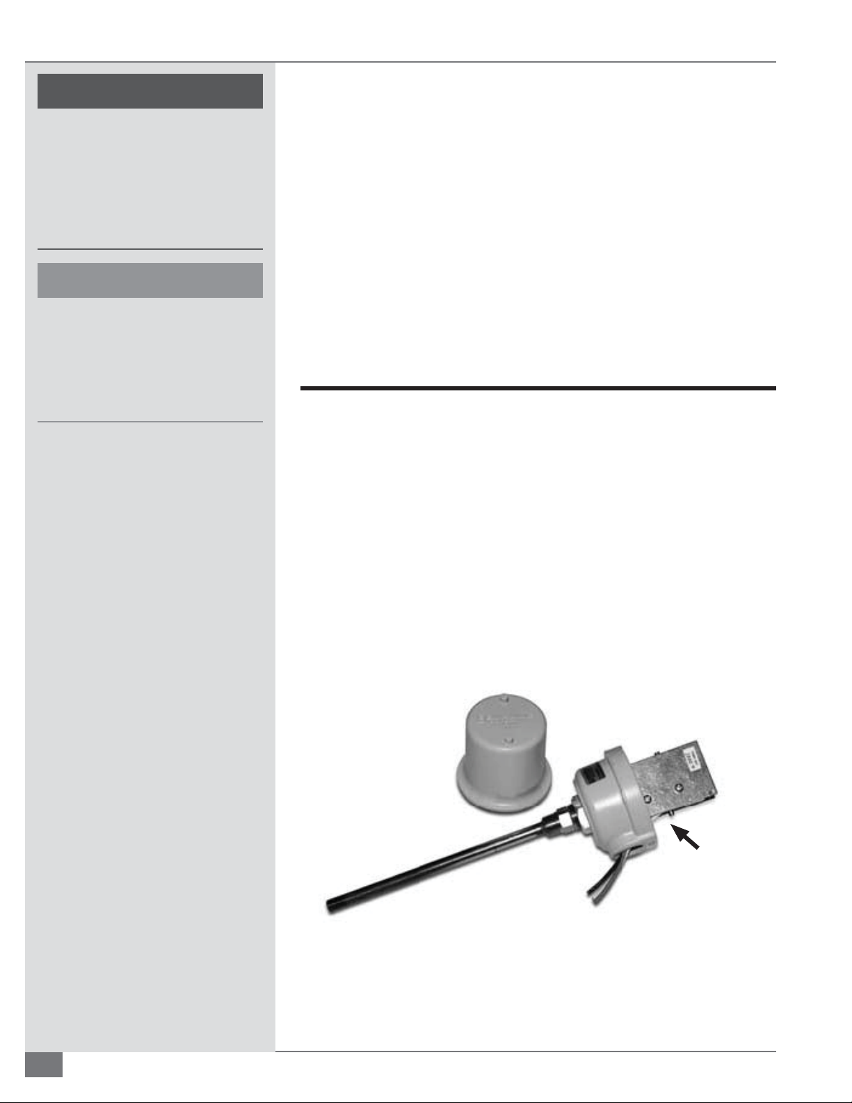
MAINTENANCE FTCS-IOM-2013-1114 SECTION 4
! WARNING
All information in this manual is for
reference and guidance purposes,
and does not substitute for required
professional training, conduct,
and strict adherence to applicable
jurisdictional/professional codes and
regulations.
4 CAUTION
All maintenance procedures should
be completed by trained personnel.
Appropriate training and instructions
are available from the Fulton Service
Department at (315) 298-5121 or your
local Fulton Thermal Representative.
Soot Cleaning
If your coil inspection indicates severe sooting, the following procedure should
be followed:
1. Make sure the heater is o and uid is ambient temperature.
2. Remove the burner and lower access doors.
3. Wire brush coils and use compressed air where accessible.
4. Vacuum loose soot where accessible.
5. Reinstall the burner and lower access doors.
6. Fire the heater and set combustion.
Safety Check Procedures
Perform the following safety checks as needed:
Liquid Level Switch
Manually turn liquid level switch cam counterclockwise. See Figure 15. Microswitch will open contacts and control voltage will be lost. Release cam and
micro-switch will make and control voltage will be restored.
Stack Limit
The limit manufacturer presets the stack limit. Testing can be performed by
removing switch from stack and applying heat over that of the switch set point
for several seconds. The switch can then be reset and re-installed. See Figure 29.
Manual Reset
FIGURE 29 STACK LIMIT SWITCH
4-6
© The Fulton Companies 2013
Page 75
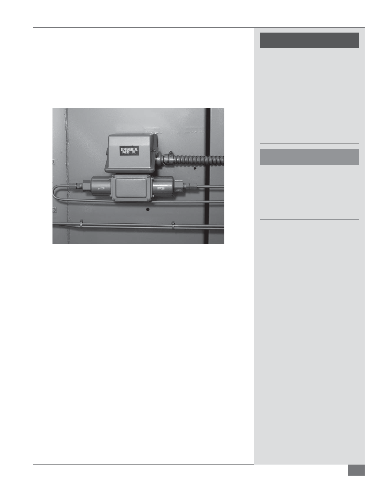
SECTION 4 FTCS-IOM-2013-1114 MAINTENANCE
Diff erential Pressure Switch
With the circulating pump running, observe the di erence in pressure between
the heater outlet gauge and the heater inlet gauge. Remove the top cover of the
di erential pressure switch. Note the original setting of the switch. The setpoint
should be 2 - 3 psi below the published di erential pressure of the heater (this
will vary by heater model, refer to Product Data Submittals). See Figure 30.
! WARNING
All information in this manual is for
reference and guidance purposes,
and does not substitute for required
professional training, conduct,
and strict adherence to applicable
jurisdictional/professional codes and
regulations.
At no time should the high inlet
pressure switch be set above the safety
relief valve set pressure.
4 CAUTION
All maintenance procedures should
be completed by trained personnel.
Appropriate training and instructions
are available from the Fulton Service
Department at (315) 298-5121 or your
local Fulton Thermal Representative.
FIGURE 30 DIFFERENTIAL PRESSURE SWITCH
Low Inlet Pressure Switch
Slowly close the valve on outlet of main circulating pump observing heater inlet
pressure gauge. Note the pressure at which the switch trips. The setpoint should
be 10 psi lower than the heater inlet pressure when the system is at operating
temperature (or 50 psig, whichever is less). See Figure 6.
High Inlet Pressure Switch
Note the original setting of the switch and turn adjustment screw
counterclockwise while observing heater inlet pressure gauge until switch trips.
The pointer on the switch should be within 2 psi of the observed pressure.
The setpoint should be 25 psi above the heater inlet pressure when the system
is cold; however, at no time should the switch be set above the safety relief valve
set pressure.
High Outlet Pressure Switch
Note the original setting of the switch and turn adjustment screw
counterclockwise while observing heater outlet pressure gauge until switch trips.
The setpoint should be 25 psi higher than the heater outlet pressure when the
system is at operating temperature and pressure; however, at no time should the
switch be set above the safety relief valve set pressure. See Figure 17.
Questions? Call (315) 298-5121, or visit us online at www.fulton.com
4-7
Page 76

MAINTENANCE FTCS-IOM-2013-1114 SECTION 4
! WARNING
All information in this manual is for
reference and guidance purposes,
and does not substitute for required
professional training, conduct,
and strict adherence to applicable
jurisdictional/professional codes and
regulations.
4 CAUTION
All maintenance procedures should
be completed by trained personnel.
Appropriate training and instructions
are available from the Fulton Service
Department at (315) 298-5121 or your
local Fulton Thermal Representative.
Air Switch
Remove the ¼” copper tubing from the bottom of the air switch with the fan
running. Air switch should trip the interlock circuit. Re-attach copper tubing and
reset ame programmer.
Air Filter Box Switch
With heater running at high re, block opening to air lter box by 50%. Slowly close
o further until switch trips. Air lter switch should trip at just over 50% blockage.
Monitor combustion valves during this procedure.
Temperature Limit(s)
Adjust set point(s) of temperature limit(s) down to a point lower than the process
variable (PV). PV is typically the current uid temperature at the heater outlet.
Solid-state controls will deactivate a control relay powering a set of n.c. contacts
in the interlock circuit. Analog controls will open their contacts in the interlock
circuit. Trip temperature should be within 5 degrees of PV temperature. Reset
temperature limit if reset exists and reset ame programmer.
High/Low Gas Pressure Switch
TESTING OF LOW GAS PRESSURE SWITCH
While boiler is running, increase the ring rate to the highest modulation rate
(usually 100 percent high re); increase the dial on the low gas pressure switch
keeping note of the pressure at which the switch trips and the boiler locks out.
Once the low gas pressure switch trips, decrease the low gas pressure switch
50 percent lower than the trip position (e.g., boiler trips at 10, decrease dial to
5). Once dial is set to desired range, reset the pressure switch and the ame
programmer and turn boiler on. Observe for proper operation.
TESTING OF HIGH GAS PRESSURE SWITCH
While boiler is running, decrease the ring rate to the lowest modulation rate
(usually 0 percent low re); decrease the dial on the high gas pressure switch
keeping note of the pressure at which the switch trips and the boiler locks out.
Once the high gas pressure switch trips, increase the high gas pressure switch
50 percent higher than the trip position (e.g., boiler trips at 10, increase dial to
15). Once dial is set to desired range, reset the pressure switch and the ame
programmer and turn boiler on. Observe for proper operation.
NOTE: High gas pressure switch may sense pressure before or after gas
butter y valve. This will impact testing of high gas pressure switch. In a
case where gas is sensed before butter y valve, use instructions above. If
sensing line is after the butter y valve, test the high gas pressure switch
during high re position (usually 100 percent high re). This is where the
most gas pressure will be present. In some cases, you may have to close the
ball valve after the gas butter y valve and the high gas pressure switch to
make it trip.
4-8
© The Fulton Companies 2013
Page 77

SECTION 4 FTCS-IOM-2013-1114 MAINTENANCE
Troubleshooting
Flow Circuit/ Circulating Pump(s)
The ow circuit is the electrical circuit that enables the
circulating pump(s). Your thermal uid pump(s) will remain on
until the ow circuit opens to disable the pump starter or the
O / Pump / Heat switch is turned to the “O ” position. Items in
the ow circuit may include paddle type ow switches, a high
inlet pressure switch, a low inlet pressure switch, a high outlet
pressure switch and a di erential pressure switch.
LOW INLET PRESSURE SWITCH
All C-Model heaters have a Low Inlet Pressure Switch. This is
a normally open switch that closes with proper heater inlet
pressure.
The purpose of the Low Inlet Pressure Switch is primarily to
protect the heater from a low ow condition. The switch senses
low backpressure downstream, indicating a change in valve
position (or a dirty strainer).The Low Inlet Pressure Switch
should be set 10 psi lower than the heater inlet pressure when
the system is at operating temperature (or 50 psig; whichever
is less), assuming that none of the conditions indicated in
Table 10-A are true. Refer to Table 10-A for a tripped Low Inlet
Pressure Switch.
The purpose of the Flow Switch(es) is to protect the heater coil
from too high of a temperature and to protect the thermal
uid from exceeding its maximum lm temperature. Each ow
switch is wired in series requiring ow through each pipe in the
coil. Refer to Table 10-C for ow switch troubleshooting.
HIGH INLET PRESSURE SWITCH
Units newer than mid-1993 have a High Inlet Pressure Switch.
This is a normally closed switch that opens with improper
heater inlet pressure.
The purpose of the High Inlet Pressure Switch is to protect the
heater from building too high of a pressure.
Typical coil model heaters have a maximum working pressure
of 150 psi with 100 psi safety valve(s) on the heater outlet
manifold. The High Inlet Pressure Switch should be set at
25 psi over the heater inlet pressure when system is cold.
At no time should the switch be set above the safety relief
valve set pressure. Reference conditions in Table 10-D for
troubleshooting.
DIFFERENTIAL PRESSURE SWITCH
Units newer than mid-1993 have a Di erential Pressure Switch.
This is a normally open diaphragm switch that closes with a
proper heater di erential pressure between the heater inlet
and outlet.
HIGH OUTLET PRESSURE SWITCH
All C-Model heaters have a High Outlet Pressure Switch. This is a
normally closed switch that opens with excessive heater outlet
pressure.
The purpose of the High Outlet Pressure Switch is primarily to
protect the heater from building too much pressure. Typical coil
model heaters have a maximum working pressure of 150 psi
with 100 psi safety valve(s) on the heater outlet manifold.
The setpoint should be 25 psi above the heater outlet
pressure when the system is at operating pressure and
temperature; however, at no time should the switch be set
above the safety relief valve set pressure.
Refer to Table 10-B for a tripped High Outlet Pressure Switch,
which will require the manual reset button on the switch to be
pushed.
FLOW SWITCHES
Units older than mid-1993 have Flow Switches on the inlet of
each pipe in the coil. These are normally open switches that
close, making a micro-switch, upon ow establishment.
The purpose of the Di erential Pressure Switch is to protect the
heater coil from too high of a temperature and to protect the
thermal uid from exceeding its maximum lm temperature.
The setpoint should be 2 - 3 psi below the published
di erential pressure of the heater (this will vary by heater
model).
This pressure is the di erence in pressure between the heater
inlet pressure gauge and the heater outlet pressure gauge. See
Table 10-E for troubleshooting.
CALL FOR HEAT/BURNER INTERLOCK
The call for heat circuit is the circuit that enables burner
operation. Fulton Thermal Corporation has used a variety of
Temperature Controllers to act as the Call for Heat. Generally
these controls work in combination with a control relay. When
the Temperature Controller calls for heat, a signal is sent to the
coil of a control relay that closes a normally open set of contacts
in series with the burner circuit.
When the call for heat is met, the signal is removed and
the contacts return to their open state. Situations that may
interfere with the Call for Heat circuit are in Table 10-F. The
Questions? Call (315) 298-5121, or visit us online at www.fulton.com
4-9
Page 78

MAINTENANCE FTCS-IOM-2013-1114 SECTION 4
burner interlock is the electrical circuit that enables the ame
programmer. Your thermal heater needs to have the items in
the burner interlock ‘made’ before ignition can occur. Items in
the burner interlock may include an air switch, air lter switch,
auxiliary blower motor starter contacts, high temperature
limit(s), high gas pressure switch, low gas pressure switch, and /
or low oil pressure switch.
AIR SWITCH
All C-model heaters have an Air Switch. This is a normally open
switch that closes with proper burner fan outlet pressure. This
switch is generally a diaphragm type switch.
The Air Switch is a safety device that proves that there is an
adequate pressure and volume of make up air for proper
combustion and mixing. There is no manual reset on the air
switch itself to indicate a trip. The most likely time of an air
switch trip is at low re purge or low re. If this switch trips, it is
generally one of the issues indicated in Table 10-G.
AIR FILTER SWITCH
C-model heaters with an air lter box or ducted supply air have
an Air Filter Switch. This is a normally closed switch that opens
on too high of a suction pressure at the burner fan inlet. This
switch is generally a diaphragm type switch.
The Air Filter Switch is a safety device that proves that there is
not too negative of a pressure at the combustion blower inlet.
This switch is only used on units that have a built in air box for
use as a duct connection or air ltering device.
There is no manual reset on the air lter switch itself to indicate
a trip. The most likely time of an air lter switch trip is at high
re purge or high re. If this switch trips, it is generally one of
the issues indicated in Table 10-H.
AUX. BLOWER MOTOR STARTER
Limit. The high temperature limit(s) is/are normally closed
switch(es) that break on a temperature rise over set point.
The switch may be either a solid state controller or a bulb and
capillary type switch. The High Temperature Limit is a safety
device that protects the thermal uid and heat transfer coil
from excessively high temperatures.
Solid-state high temperature limits will have a manual reset.
Bulb and capillary type limits will not have a manual reset.
If this/these switch(es) trips, it is generally one of the issues
indicated in Table 10-J.
HIGH GAS PRESSURE SWITCH
All gas- red modulating or NFPA rated thermal uid heaters
have a High Gas Pressure Switch. This is a normally closed
diaphragm switch that opens on a pressure increase over set
point. The High Gas Pressure Switch is a safety device that
protects the burner from receiving too high of a gas pressure.
The switch senses this pressure downstream of the last
gas valve, upstream of the modulation valve on units that
modulate.
This switch is most likely to trip at low re. If this switch trips, it is
generally one of the issues indicated in Table 10-K.
LOW GAS PRESSURE SWITCH
All gas- red modulating or NFPA rated thermal uid heaters
have a Low Gas Pressure Switch. This is a normally closed
diaphragm switch that opens on a pressure decrease below set
point.
The Low Gas Pressure Switch is a safety device that protects
the burner from receiving too low of a gas pressure. The switch
senses this pressure just downstream of the gas regulator. This
switch will most likely trip at high re. If this switch trips, it is
generally one of the issues indicated in Table 10-L.
All C-model heaters use an auxiliary set of contacts on their
blower motor starter to prove that the burner motor is latched
on. This is a normally open set of contacts mounted on or built
in to the blower motor starter. The Auxiliary Blower Motor
Contacts are a safety device that proves that the blower motor
starter is latched in. These contacts work in redundancy to the
air switch to prove that there is proper makeup air. There is no
manual reset on the auxiliary contacts themselves to indicate a
trip. If the contacts do not make, it is generally one of the issues
indicated in Table 10-I.
HIGH TEMPERATURE LIMIT
All thermal uid heaters have at least one High Temperature
4-10
LOW OIL PRESSURE SWITCH
All oil red modulating thermal uid heaters have a Low Oil
Pressure Switch. This is a normally closed diaphragm switch
that opens on a pressure decrease below set point. The Low
Oil Pressure Switch is a safety device that protects the burner
from receiving too low of an oil pressure. The switch senses this
pressure just downstream of the gas pump. If this switch trips, it
is generally one of the issues indicated in Table 10-M.
PILOT FLAME FAILURE
A Pilot Flame Failure is a ame failure that occurs when the
unit is trying to establish an adequate ame signal. Solid-state
© The Fulton Companies 2013
Page 79
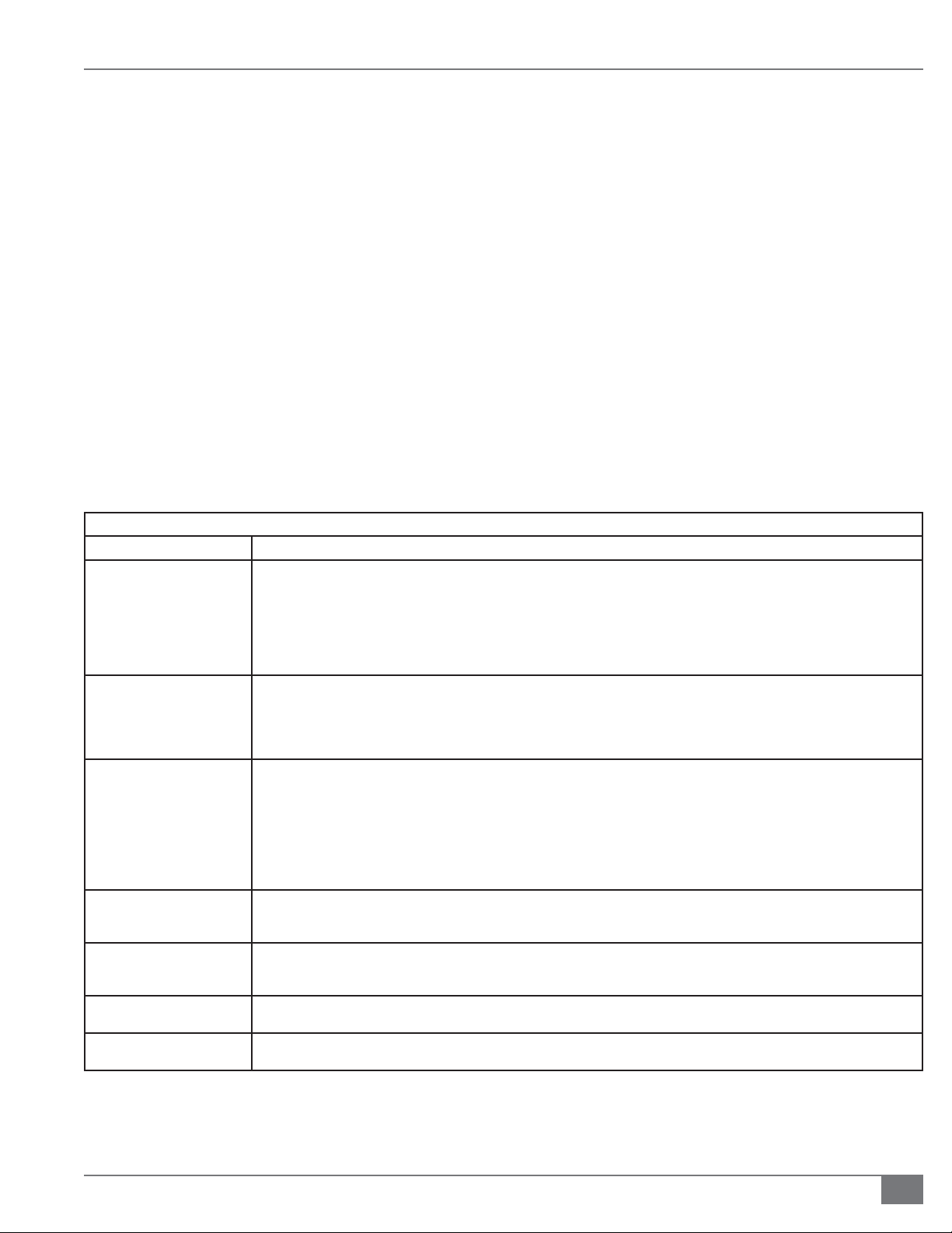
SECTION 4 FTCS-IOM-2013-1114 MAINTENANCE
controllers indicate a Pilot Flame Failure by showing as a fault
code either Fault 28 for Honeywell 7800 series controllers.
Flame Failure PTFI on Fireye E110 series controllers or Fault
9 on Fireye Nexus controls. For electro-mechanical controls,
you need to witness when the failure occurs. A Pilot Flame
Failure indicates that either a strong enough pilot ame
was not generated or the means of sensing the pilot ame
Main Flame Trial for Ignition.
Solid state controllers indicate a Main Flame Failure by
showing as a fault code of either Fault 19 for Honeywell 7800
series controllers, Flame Failure MTFI on Fireye E110 series
controllers, or a Fault 09 for Fireye Nexus controls. For electromechanical controls, you need to witness when the failure
occurs.
strength has failed. All gas red units have a gas pilot. Oil red
units may be 2-stage, in which the 1st stage to light would be
considered the pilot, or may have a gas pilot. In either case,
during the pilot proving period, the ame programmer must
sense a strong enough ame to initiate the opening of the
main valves.
A Main Flame Failure indicates that either a strong enough
main ame was not generated or the means of sensing
the main ame strength has failed. During the main ame
proving period, the ame programmer must sense a strong
enough ame to hold the main valves open. If you are
experiencing Main Flame Failures, check the items indicated
MAIN FLAME FAILURE
in Table 10-O.
Main Flame Failure is a ame failure that occurs while the
unit is trying to establish an adequate ame signal during the
TABLE 10A LOW INLET PRESSURE SWITCH TROUBLESHOOTING
Problem Potential Remedy
Plugged circulation pump
strainer basket
Failed Circulation Pump
Coupling
Cavitation of the circulating
pump
System is open Lack of back-pressure. If control valving is improper or pressure drop across the system is too low, the resulting minimal back-
Blocked Sensing Line on
Pressure Switch
Improper Switch Setting Low Inlet Pressure Switch should be set at 10 psi less than the pressure read on the heater inlet pressure gauge at full operating
Switch is faulty If pressure is veri ed and reads correctly above set point on switch and the sensing line to the pressure switch is open, the pressure
A plugged strainer will result in a decrease of ow through the heater. High vacuums developed from plugged strainers can also
stress the seals of the pump causing the pump to fail.
A “Pump Suction” gauge is provided on Fulton Thermal skids to help determine when a strainer needs cleaning. Generally this point
is between 0 and -5” Hg.
If the strainer is plugged, isolate the strainer and drain that section of piping being mindful of the temperature of the thermal uid.
Remove the strainer and clean with compressed air, high-pressure water or a cleaning solution. Replace and observe new pump
suction pressure.
A failed coupling will result in a decreased or no ow condition through the heater. The coupling can be checked by removing the
coupling guard between the pump and pump motor.
The coupling should not be torn or misshapen. If the coupling needs to be replaced, it is recommended to re-align the circulating
pump rst at ambient temperature and again when it’s at operating temperature. Alignment should be within pump manufacturers’
speci cations
Cavitation occurs when a pump experiences a loss of head or if any low heater ashes to gas at the impeller. During this time, the
pump impeller spins without actually circulating any thermal uid.
If Fulton Thermal Corporation provided the heater skid, loss of head to the pump is extremely unlikely with proper uid level in the
combination tank.
The most common low heater in a thermal piping system is water, which needs to be boiled out at startup or anytime new piping or
uid is added to the thermal oil system.
Once the system has been brought up to full operating temperature, assuming that the entire system has seen ow, there should be
no further occurrence of low heater contamination apart from possible heat exchanger failure.
pressure may not provide enough resistance for the ow to make the pressure switch. Check the thermal uid system for proper
operation of control valves.
A blocked sensing line will give an inaccurate pressure reading to the pressure switch. A blocked line will need to be replaced or
cleaned. Most installations have block valves at the heater to facilitate safe isolation and cleaning of the sensing line. Do not attempt
when system is hot.
temperature of the system; or 50 psig, whichever is less.
switch is faulty. Replace switch, set for desired set point and test for proper operation.
Questions? Call (315) 298-5121, or visit us online at www.fulton.com
4-11
Page 80
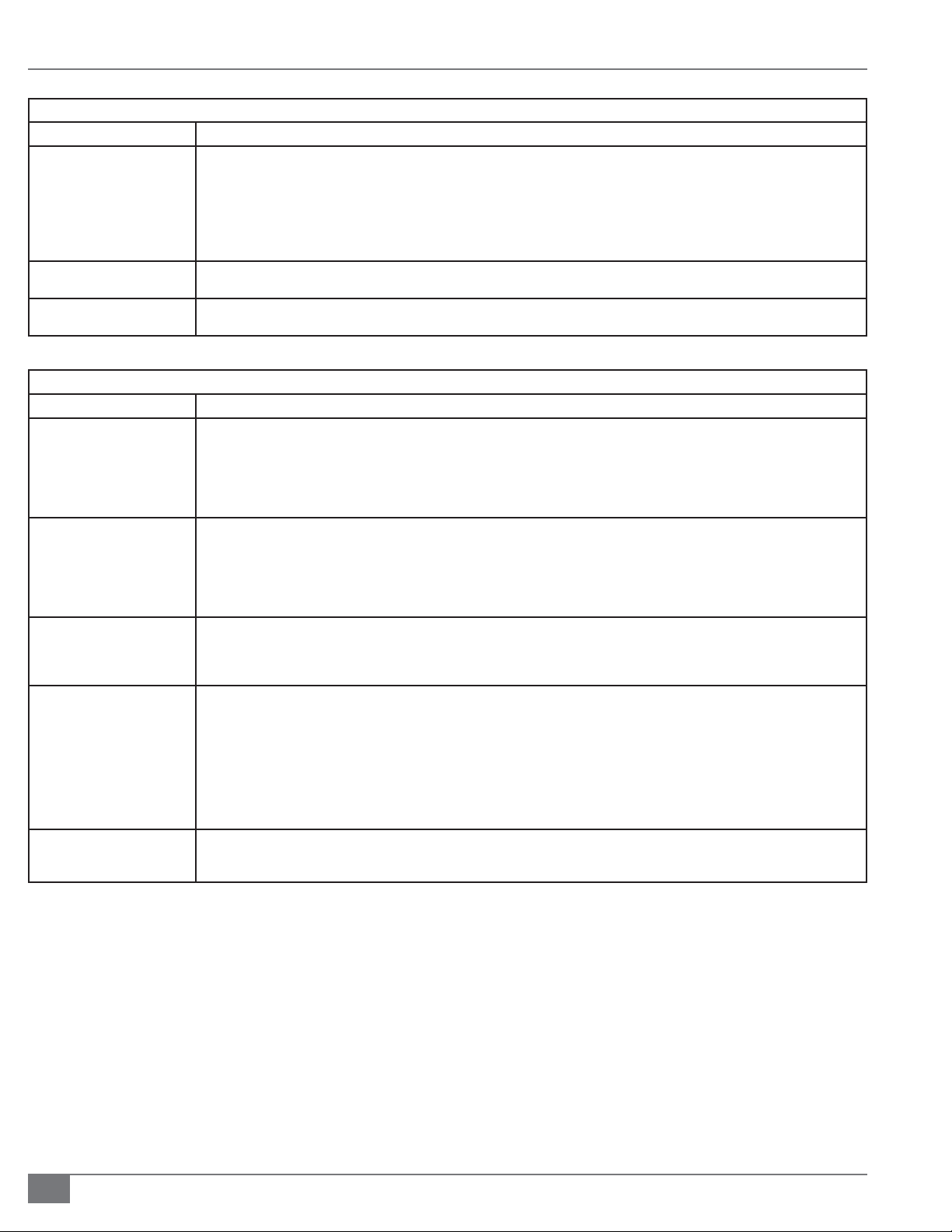
MAINTENANCE FTCS-IOM-2013-1114 SECTION 4
TABLE 10B HIGH OUTLET PRESSURE SWITCH TROUBLESHOOTING
Problem Potential Remedy
An obstruction downstream of
the heater
Improper Switch Setting The High Outlet Pressure Switch should be set at 25 psi higher than the heater outlet pressure when the system is at operating
Faulty Switch If pressure is veri ed and reads correctly below set point on switch and the sensing line to the pressure switch is open, the pressure
TABLE 10C FLOW SWITCHES TROUBLESHOOTING
Problem Potential Remedy
An obstruction downstream of
the Flow Switch(es)
Plugged circulation pump
strainer basket
Failed circulation pump
coupling
Cavitation of the circulating
pump
Any obstruction downstream of the heater will increase the pressure that the heater outlet sees. This obstruction will generally result
from an improper valve setting.
Observe heater outlet pressure at temperature with all users / heat exchangers calling for heat (100% user). Observe heater outlet
pressure at temperature with all users / heat exchangers not calling for heat (100% bypass). Bypass regulating valve(s) should be
adjusted to equal ow condition through users.
Call or e-mail Fulton for further details. It may be possible that an automatic control valve has failed. If this is the case, the valve
actuator should be inspected and possibly replaced.
temperature and pressure. At no time should the switch be set above the safety relief valve set pressure.
switch is faulty. Replace switch, set for desired set point and test for proper operation.
Any obstruction downstream of the ow switch(es) will increase the pressure that the heater outlet sees. Any increase in outlet
pressure will result in diminished ow. This obstruction will generally result from an improper valve setting.
Observe heater outlet pressure at temperature with all users / heat exchangers calling for heat (100% user). Observe heater outlet
pressure at temperature with all users / heat exchangers not calling for heat (100% bypass). Bypass regulating valve(s) should be
adjusted to equal ow condition through users. Call or e-mail Fulton for further details. It may be possible that an automatic control
valve has failed. If this is the case, the valve should be replaced.
A plugged strainer will result in a decrease in ow through the heater. High vacuums developed from plugged strainers can also
stress the seals of the pump causing the pump to fail.
A “Pump Suction” gauge is provided on Fulton Thermal skids to help determine when a strainer needs cleaning. Generally this point
is -2 psi (5 in. Hg).
If the strainer is plugged, isolate the strainer and drain being mindful of the temperature of the thermal uid. Remove the strainer
and clean with compressed air, high-pressure water or a cleaning solution. Replace and observe new heater inlet pressure.
A failed coupling will result in a decreased or no ow condition through the heater. The coupling can be checked by removing
the coupling guard between the pump and pump motor. The coupling should not be torn or misshapen. If the coupling needs
to be replaced, it will be necessary to re-align the circulating pump rst at ambient temperature and again when it’s at operating
temperature.
Cavitation occurs when a partial vacuum presents itself at the eye of the pump impeller due to loss of head or if any low heater
ashes to gas at the impeller.
During this time, the pump impeller spins without actually circulating any thermal uid. If Fulton Thermal Corporation provided the
heater skid, loss of head to the pump is extremely unlikely with proper uid level in the tank.
The most common low heater in a thermal piping system is water, which needs to be boiled out at startup.
Once the system has been brought up to full operating temperature, assuming that the entire system has seen ow, there should be
no further occurrence of low heater contamination apart from heat exchanger failure.
Plugged coil pipe(s) If too low of a ow condition has occurred for too long a period of time or if the maximum operating temperature of the oil has been
exceeded, it is possible, however unlikely, that a pipe or pipes in the coil could plug with solids. If this occurs, it will be necessary to
shut down the system and clean the coil. Fulton Thermal Corporation should be consulted in this matter.
4-12
© The Fulton Companies 2013
Page 81

SECTION 4 FTCS-IOM-2013-1114 MAINTENANCE
TABLE 10D HIGH INLET PRESSURE SWITCH TROUBLESHOOTING
Problem Potential Remedy
An obstruction downstream of
the heater
Plugged Coil Pipes If too low of a ow condition has occurred for too long a period of time or if the maximum operating temperature of the oil has been
Improper Switch Setting The High Inlet Pressure Switch should be set at 25 psi above the heater inlet pressure when the system is cold. At no time should
TABLE 10E DIFFERENTIAL PRESSURE SWITCH BREAK TROUBLESHOOTING
Problem Potential Remedy
An obstruction downstream of
the heater outlet
Any obstruction downstream of the heater will increase the pressure that the heater outlet sees. This obstruction will generally result
from an improper valve setting.
Observe heater outlet pressure at temperature with all users / heat exchangers calling for heat (100% user). Observe heater outlet
pressure at temperature with all users / heat exchangers not calling for heat (100% bypass).
Bypass regulating valve(s) should be adjusted to equal ow condition through users. Call or e-mail Fulton for further details.
It may be possible that an automatic control valve has failed. If this is the case, the valve should be replaced.
exceeded, it is possible, however unlikely, that a pipe or pipes in the coil could plug with solids. If this occurs, it will be necessary to
shut down the system and clean the coil. Fulton Thermal Corporation should be consulted in this matter.
the switch be set above the safety relief valve set pressure.
Any obstruction downstream of the ow switch(es) will increase the pressure that the heater outlet sees. Any increase in outlet
pressure will result in diminished ow. This obstruction will generally result from an improper valve setting.
Observe heater outlet pressure at temperature with all users / heat exchangers calling for heat (100% user). Observe heater outlet
pressure at temperature with all users / heat exchangers not calling for heat (100% bypass).
Bypass regulating valve(s) should be adjusted to equal ow condition through users. Call or e-mail Fulton for further details.
It may be possible that an automatic control valve has failed. If this is the case, the valve should be replaced.
TABLE 10F CALL FOR HEAT CIRCUIT TROUBLESHOOTING
Problem Potential Remedy
Programming Problem Fulton has a general program for each of the temperature controllers we have used over the years. Compare your
current temperature controller program to Fulton’s general program.
See the back of this section for general programming sheets for standard Fulton heaters.
Make changes as necessary. Contact Fulton service department with any questions.
Temperature Controller
Failure
Temperature Sensor
Failure
Control Relay May Have
Failed
If the temperature controller is calling for heat but is not putting power on the output to the control relay, the relay
will not close the normally open contacts and the heater will remain disabled. If this is the case, some controllers
have separate sets of contacts that may be utilized in replacement of the damaged contacts. Some rewiring and/or
reprogramming will be needed. Contact Fulton service department if necessary.
Di erent temperature controllers use di erent types of temperature sensors. These may be Type J thermocouples,
mercury bulbs, RTDs or another type of sensor. It is possible for these sensors to malfunction. To verify proper sensor
operation, use an alternate source of temperature detection such as an infra-red temperature sensor to sense
temperature at the same point.
Many temperature controllers energize a relay with a call for heat that in turn closes a normally open set of contacts to
energize the burner circuit.
If your temperature controller is sending an output signal to the control relay but the burner is not initiated, check
resistance across coil of the relay. An open reading indicates that the relay needs to be replaced. If the coil shows
resistance, energize coil and check contacts. With coil energized, normally open contacts should close resulting in a
reading of control voltage on both the common and normally open contact.
If voltage exists on common but not on normally open contact either switch contacts if another set of normally open
contacts are available or replace relay.
Questions? Call (315) 298-5121, or visit us online at www.fulton.com
4-13
Page 82
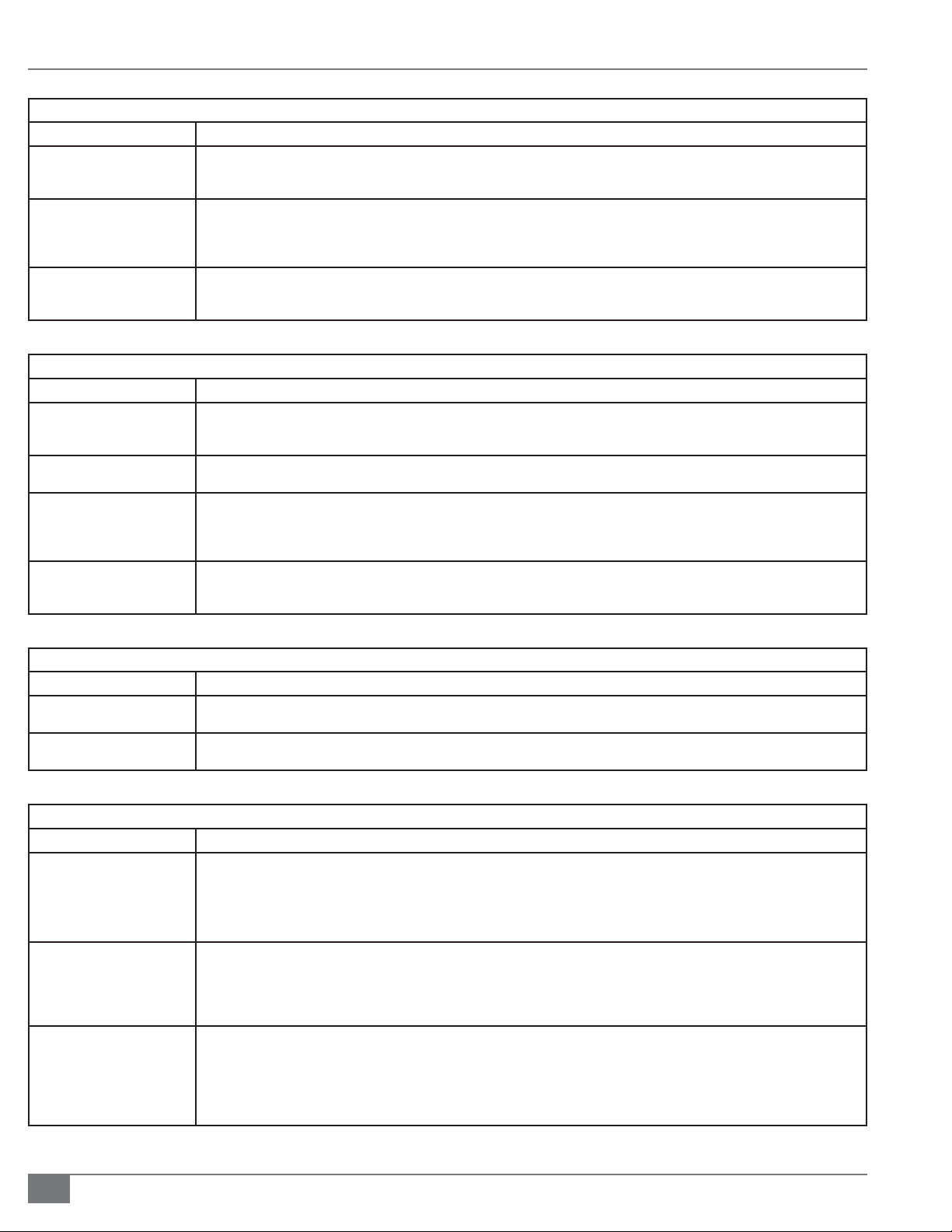
MAINTENANCE FTCS-IOM-2013-1114 SECTION 4
TABLE 10G AIR SWITCH TROUBLESHOOTING
Problem Potential Remedy
Combustion Blower Fan is
Dirty
The sensing line is plugged,
crimped or pointing in the
wrong area
The Switch setting is improper The adjustment screw for the air switch is located opposite the electrical connections. A gray cap covers the screw. Turn the screw
TABLE 10H AIR FILTER SWITCH TROUBLESHOOTING
Problem Potential Remedy
The air lter is dirty If the air lter becomes dirty, the fan will generate greater suction. Too much suction will result in not enough air ow for proper
There is an obstruction in the
make-up air ducting
The sensing line is pointing in
the wrong direction
Switch setting is improper The adjustment screw for the air switch is located opposite the electrical connections. A gray cap covers the screw. Turn the screw
If the cups of the squirrel cage type fan become dirty, less air will be moved by the fan. If the fans are dirty enough, there will not be
enough air ow for the air switch to prove. You should assure that the combustion blower fan is clean, reset the ame programmer
and try to light unit again
If the sensing line to the air switch is crimped or blocked, the switch will not sense the proper pressure. Ensure that the sensing line
is clear and not crimped by removing both sides of the sensing line and using compressed air to blow through the line. Also ensure
that the elbow acting as an air scoop is pointing directly into the air stream. Reset the ame programmer and try to light the unit
again.
clockwise to increase setting, counter-clockwise to decrease setting. To set switch, run unit at low re. Increase setting 1/2 turn every
5 seconds until unit trips on interlock. Decrease setting by 2 full turns. Reset unit.
combustion and mixing and will cause air switch to trip. You should regularly change lters on a schedule dependent on how dirty the
makeup air is. After checking or changing air lter, reset the ame programmer and try to light unit again.
Units that have make-up air ducting need to assure that blockage to the ducting does not occur. Check outside termination and any
bends in the ducting for blockage. Clear blockage, reset ame programmer and try to light unit again.
The sensing line for the air lter switch is supposed to provide the static pressure of the air box. The termination of the sensing line
should be pointing in the direction that limits its contact with moving air. If the sensing line is pointed perpendicularly to entering air
stream, the switch will not sense the proper pressure and could give a false indication of air box suction. Reset the ame programmer
and try to light the unit again.
clockwise to increase setting, counter-clockwise to decrease setting. The switch setting should be set in such a way that with 50 % of
the air box opening blocked, the switch will trip. Reset switch setting, reset the ame programmer, and try to light the unit again.
TABLE 10I AUXILIARY BLOWER MOTOR STARTER TROUBLESHOOTING
Problem Potential Remedy
The blower motor starter coil
is bad
The auxiliary contacts are
burned or pitted
If this is the case, the blower starter will not latch in. Check for voltage to the coil. If proper voltage is present and the starter does not
pull in, that proves the coil is bad. Replace the starter, reset the ame programmer and try to light unit again.
Visibly inspect contacts. With power o , attempt to clean or replace starter if damaged. Reset ame programmer and try to light unit
again.
TABLE 10J HIGH TEMPERATURE LIMIT TROUBLESHOOTING
Problem Potential Remedy
Flow rate is too low Too low of a ow rate will result in a higher rate of heat transfer to the thermal uid and heat transfer coils. This will result in a
higher temperature di erence between inlet temperature and outlet temperature.
It is important to make sure that the minimum ow rate as speci ed by Fulton for that speci c model is maintained Check inlet
and outlet pressures of the heater to determine di erential pressure and ow rate. Ensure that this ow rate meets or exceeds
minimums speci ed by Fulton (see chart). Also check di erential pressure switch for proper operation and setting.
Heater is over- red If the heater has more fuel input than design, it is probable that the heat transfer rate will increase beyond design. Check input to
heater at high re for modulated heaters or at the standard rate for on / o units. This can be done by either using a corrected gas
meter reading or measuring gas pressure supplied to the burner compared to factory test- re settings.
If input is improper, inspect burner as described below. If burner is not damaged or have improper components, adjust fuel input
and combustion to speci cation.
Gas- red burner is damaged Pull and inspect the burner. Primary areas of concern for gas- red units are the ori ce plate, pilot assembly seating and ori ce plate
gap.
If the ori ce plate is warped or burned through, pilot assembly is not seated or gap between ori ce plate and gas tube is improper,
more fuel than designed for will enter the furnace.
This will cause the heater to have more fuel input than designed for. The design ow rate will then be too low causing the uid to
heat up higher than it should.
4-14
© The Fulton Companies 2013
Page 83

SECTION 4 FTCS-IOM-2013-1114 MAINTENANCE
TABLE 10K HIGH GAS PRESSURE SWITCH TROUBLESHOOTING
Problem Potential Remedy
Gas pressure setting on the
main regulator is too high
Low re gas valve setting is
too low
Gas pressure switch setting is
improper
Gas regulator has failed open This is highly unlikely. Regulators will usually fail safe in the closed position. The gas regulator can be checked by checking upstream
TABLE 10L LOW GAS PRESSURE SWITCH TROUBLESHOOTING
Problem Potential Remedy
Gas pressure setting on the
main regulator is too low
Gas ori ce plate is damaged If the ori ce plate is damaged, it may be holding back less gas creating a lower pressure on the sensing switch. Pull burner and
Gas regulator has failed closed Regulators will usually fail safe in the closed position. The gas regulator can be checked by checking upstream pressure and
With unit running at high re, make sure that the modulated gas valve is at full open.
Since unit lights at low re, it may be necessary to increase high gas pressure setting or jumper contacts to allow unit to modulate to
where modulation gas valve back pressure is lessened.
Check net last elbow gas pressure and compare to factory test re sheet. Net gas pressure is running gas pressure minus p urge
pressure. Make sure net pressure reading is within .2” w.c. of factory reading. If there is a di erence, adjust main regulator. Adjust for
proper combustion throughout range.
Because the sensing point of the High Gas Pressure Switch is upstream of the modulating gas valve, the highest pressure read will
occur during low re.
Check net last elbow gas pressure and compare to factory test re sheet. Net gas pressure is running gas pressure minus purge
pressure. Make sure net pressure reading is within .1” w.c. of factory reading. If there is a di erence, adjust modulating gas valve
linkage. Adjust for proper combustion throughout range.
If above two items are proper, check the pressure that the high gas pressure switch is sensing by way of a tee installed in the line.
Hold unit at low re and check pressure. Setting on switch should be 10% over pressure read. Call Fulton if you have any questions.
pressure and comparing to downstream pressure. Make sure that the upstream pressure is not above the rating of the regulator.
Make sure that the downstream pressure does not exceed the range of the spring. If regulator has failed, replace, reset input and
adjust input throughout the range.
At high re, the modulating gas valve is full open resulting in the least amount of back pressure in the gas train. With unit running
at high re, check net last elbow gas pressure and compare to factory test re sheet. Net gas pressure is running gas pressure minus
purge pressure. Make sure net pressure reading is within .2” w.c. of factory reading. If there is a di erence, adjust main regulator.
Adjust for proper combustion throughout range.
inspect gas ori ce plate. Plate should in no way be warped or degraded. If it is, replace. After reinstallation, recheck input and adjust
combustion throughout range.
comparing to downstream pressure. Make sure that the upstream pressure is not above the rating of the regulator. If regulator has
failed, replace, reset input and adjust input throughout the range.
TABLE 10M LOW OIL PRESSURE SWITCH TROUBLESHOOTING
Problem Potential Remedy
Oil pressure setting on the
back pressure valve is too low
Fuel oil pump may have lost
its prime
Fuel oil pump motor may have
failed
Fuel oil pump coupling may
have failed
At low re, the modulating oil valve is at its most open position resulting in the least amount of back pressure in the fuel train. With
unit running at low re, check oil pressure and compare to factory test re sheet. Make sure oil pressure reading is within 10 psi of
factory reading. If there is a di erence, adjust back pressure regulator. Adjust for proper combustion throughout range.
An air bubble in the pump will result in a momentary loss of prime that will be enough to cause the Low Oil Pressure Switch to trip.
Ensure that oil pump is primed properly and all connections are tight. Check the pump seal. A blown seal will allow air in the pump
housing.
Check the pump motor for proper voltage. If voltage is proper but motor does not turn, replace or rebuild motor. If there is no
voltage, check motor starter for input signal and incoming 3-phase power.
A failed coupling will result in the pump not turning. Check coupling. Replace if necessary..
Questions? Call (315) 298-5121, or visit us online at www.fulton.com
4-15
Page 84

MAINTENANCE FTCS-IOM-2013-1114 SECTION 4
TABLE 10N PILOT FLAME FAILURE TROUBLESHOOTING
Problem Potential Remedy
Pilot ame strength is
inadequate
Pilot sensing device does not
work properly
Room air pressure is di erent
from outside air pressure
TABLE 10O MAIN FLAME FAILURE TROUBLESHOOTING
Problem Potential Remedy
Main ame strength is
inadequate
Flame sensing device does not
work properly
Room air pressure is di erent
from outside air pressure
Unit is experiencing too great
of a restriction
Cycle the unit. During the pilot trial for ignition, carefully observe the pilot ame strength.
On Honeywell controllers, the pilot ame strength must be between 1.25 to 5.0 VDC. On Fireye controllers, the pilot ame strength
must be greater than 10 VDC.
Current controls are supplied with a test switch that can hold the programmer in the pilot trial for ignition stage. If a pilot signal
greater that 0.0 but less than the minimum required is detected, look through the sight hole provided on the burner plate of the
heater to visibly detect ame. If ame is seen, make small adjustments to increase pilot gas and air to provide larger ame.
Cycle the unit. If a pilot signal of 0.0 is detected, look through the sight hole provided on the burner plate of the heater to visibly
detect ame.
If ame is seen, your ame detection device or ampli er may be faulty. If the unit has a ame rod, lockout and tag heater’s electrical
circuit and fuel supply. Pull pilot assembly out of unit. Inspect the ame rod. If the ame rod is corroded, shows signs of heat
impingement, has been turned o or has cracks in the porcelain, replace with a new ame rod.
Reinstall and cycle unit. If the unit has a U.V. scanner, lockout and tag heater’s fuel supply. Remove U.V. scanner from U.V. sight tube.
Make sure that the lens of the scanner is clean. Use a lighter or match and make a ame in front of the scanner eye. Lens should
icker. If unit does not icker, change U.V. scanner. If this change does not work, change U.V. ampli er. Reinstall and cycle unit.
Check room air pressure relative to outside air pressure. Heater room pressure should equal outside air pressure. Signi cant
di erences in pressure will result in an erratic ame, which will not deliver a strong ame signal.
Cycle the unit. During the main ame proving period , carefully observe the pilot ame strength. Current controls are supplied with a
test switch that can hold the programmer in the main ame proving period.
If a main signal is greater than 0.0 but less than the minimum required is detected, look through the observation port to try to visibly
see ame. A combustion change may be necessary to establish main.
If observed ame is blue, slightly decrease the air damper setting and recycle. If ame is red or orange, slightly increase air damper
setting and recycle. Once adequate ame signal is established, reset input and combustion throughout range of modulation.
Cycle the unit. If a signal of 0.0 is detected, look through the sight hole provided on the burner plate of the heater to visibly detect
ame. If ame is seen, your ame detection device or ampli er may be faulty.
If the unit has a ame rod, lockout and tag heater’s electrical circuit and fuel supply. Pull pilot assembly out of unit. Inspect the ame
rod. If the ame rod is corroded, shows signs of heat impingement, has been burned o or has cracks in the porcelain, replace with a
new ame rod. Reinstall and cycle unit.
If the unit has a U.V. scanner, lockout and tag heater’s fuel supply. Remove U.V. scanner from U.V. sight tube Make sure that the lens
of the scanner is clean. Use a lighter or match and make a ame in front of the scanner eye. Lens should icker. If unit does not icker,
change U.V. scanner. If this change does not work, change U.V. ampli er. Reinstall and cycle unit.
Check room air pressure relative to outside air pressure. Heater room pressure should equal outside air pressure. Signi cant
di erences in pressure will result in an erratic ame, which will not deliver a strong ame signal.
At the breaching of the heater, take a draft reading. Draft should read between -.02” w.c. and -.04” w.c. with the heater o and
between -.04” w.c. and -.08” w.c. with the unit on. A restrictive draft would be a draft that was positive. A restrictive draft is usually
the result a stack that is undersized, a stack with too many elbows or a stack whose cap or piping is warped and damaged. Another
source of restriction results from broken refractory. If the unit’s refractory breaks, large enough pieces could block the ue passes.
The burner should be pulled for refractory inspection. A broken refractory should be cleaned out and replaced.
4-16
© The Fulton Companies 2013
Page 85
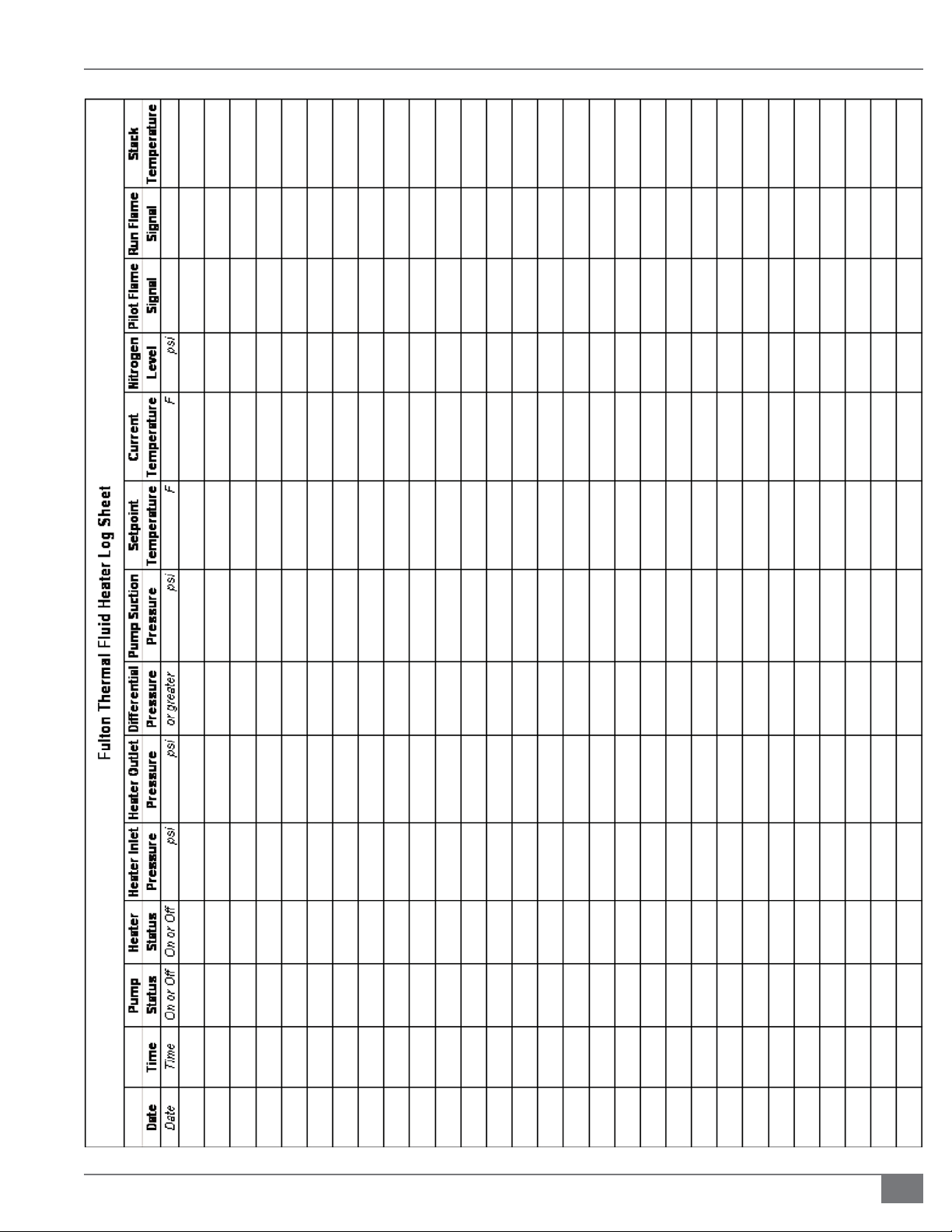
SECTION 4 FTCS-IOM-2013-1114 MAINTENANCE
Questions? Call (315) 298-5121, or visit us online at www.fulton.com
4-17
Page 86

MAINTENANCE FTCS-IOM-2013-1114 SECTION 4
4-18
© The Fulton Companies 2013
Page 87

SECTION 5 FTCS-IOM-2013-1114 PARTS & WARRANTY
INTRODUCTION
1
INSTALLATION
2
OPERATION
MAINTENANCE
PARTS & WARRANTY
3
4
5
Questions? Call (315) 298-5121, or visit us online at www.fulton.com
5-1
Page 88

PARTS & WARRANTY FTCS-IOM-2013-1114 SECTION 5
! WARNING
Use of non-factory authorized
replacement parts is not
recommended for this equipment.
Use of non-factory authorized parts
may jeopardize safety and system
performance, and voids the product
warran ty.
Parts
Spare and replacement parts may be ordered from your local representative or
through the Fulton Companies. When ordering replacement parts, please have
the model number and serial number of your Fulton boiler ready. Factory-direct
replacement parts must be used to ensure proper equipment operation and
adherance with warranty requirements. Contact Fulton Companies at (315) 2985121 for further information.
5-2
© The Fulton Companies 2013
Page 89

SECTION 5 FTCS-IOM-2013-1114 PARTS & WARRANTY
Standard Warranty for Fulton Thermal Fluid Heaters
WARRANTY VALID FOR MODELS FT-A, FT-C, FT-S, FT-N, FT-HC
ONE (1) YEAR (12 MONTH) MATERIAL AND WORKMANSHIP WARRANTY
The pressure vessel is covered against defective material or workmanship for a period of one (1) year from the date of shipment
from the factory. Fulton will repair or replace F.O.B. factory any part of the equipment, as de ned above, provided this equipment
has been installed, operated and maintained by the buyer in accordance with approved practices and recommendations made
by Fulton. All Installation and Operation Checklists must be submitted to Fulton’s Quality Assurance department. This warranty
covers any failure caused defective material or workmanship.
Thermal uid system piping and valves are painted at the factory to protect from corrosion prior to installation and operation.
These painted surfaces are not covered under warranty.
PARTS WARRANTY
Fulton will repair or replace F.O.B. factory any part of the equipment of our manufacture that is found to be defective in
workmanship or material within one (1) year of shipment from the factory provided this equipment has been installed,
operated and maintained by the buyer in accordance with approved practices and recommendations made by both Fulton
and the component manufacturers. All Installation and Operation Checklists must be submitted to Fulton’s Quality Assurance
department.
GENERAL
Fulton shall be noti ed in writing as soon as any defect becomes apparent. This warranty does not include freight, handling or
labor charges of any kind.
These warranties are contingent upon the proper sizing, installation, operation and maintenance of the boiler and peripheral
components and equipment. Warranties valid only if installed, operated, and maintained as outlined in the Fulton Installation
and Operation Manual.
No Sales Manager or other representative of Fulton other than the Quality Manager or an o cer of the company has warranty
authority. Fulton will not pay any charges unless they were pre-approved, in writing, by the Fulton Quality Manager.
This warranty is exclusive and in lieu of all other warranties, expressed or implied, including but not limited to the implied
warranties of merchantability and tness for a particular purpose. Fulton shall in no event be liable for any consequential or
incidental damages arising in any way, including but not limited to any loss of pro ts or business, even if the Fulton Companies
has been advised of the possibility of such damages. Fulton’s liability shall never exceed the amount paid for the original
equipment found to be defective.
To activate the warranty for this product, the appropriate commissioning sheets must be completed and returned to the Fulton
Quality Assurance department for review and approval.
Effective: 07.10.2013
Questions? Call (315) 298-5121, or visit us online at www.fulton.com
5-3
Page 90

PARTS & WARRANTY FTCS-IOM-2013-1114 SECTION 5
5-4
© The Fulton Companies 2013
Page 91

Page 92

No part of this Installation, Operation, and Maintenance manual
may be reproduced in any form or by any means without
permission in writing from the Fulton Companies.
Fulton Boiler Works, Inc., Fulton Heating Solutions, Inc. & Fulton Thermal
Corporation are part of the Fulton Group of Companies, a global manufacturer
of steam, hot water and thermal uid heat transfer systems.
© The Fulton Companies 2013
The heat transfer innovators.
The Fulton Companies
972 Centerville Road, Pulaski, NY 13142
Call: (315) 298-5121 • Fax: (315) 298-6390
www.fulton.com
FTCS-IOM-2013-1114
 Loading...