

Fukuda FL-296 Series, FL-286 Installation Instructions Manual
10527-T-800E-00
http://www.fukuda-jp.com
COMPACT AIR LEAK TESTER
DESIGN DOCUMENT
FL-296 SERIES
Contents
MODEL ・・・・・・・・・・・・・・・・・・・・・・・・・・・・・・・・・・・・ 6
SPECIFICATIONS ・・・・・・・・・・・・・・・・・・・・・・・・・・・・・ 7
DO YOU HAVE EVERYTHING? ・・・・・・・・・・・・・・・・・・・・・・・ 8
OPTION ・・・・・・・・・・・・・・・・・・・・・・・・・・・・・・・・・・・・ 9
INSTALLATION INSTRUCTIONS ・・・・・・・・・・・・・・・・・・・・ 14-15
AIR PIPE CONFIGURATIONS ・・・・・・・・・・・・・・・・・・・・・・ 16-17
ELECTRIC WIRING CONFIGURATIONS ・・・・・・・・・・・・・・・・・ 18-19
LINE CONNECTIONS ・・・・・・・・・・・・・・・・・・・・・・・・・・・・・ 20-35
RS-232C CONNECTION ・・・・・・・・・・・・・・・・・・・・・・・・・・ 60-63
PRINTER CONNECTIONS ・・・・・・・・・・・・・・・・・・・・・・・・ 65
EXTERNAL DIMENSIONS ・・・・・・・・・・・・・・・・・・・・・・・・ 72-74
■ Declaration
・This design documents is outline specification for system design which is extracted from operation manual
(10527-T-001E-05).
The above contents page numbers is mentioned the page numbers of operation manual.
For about details of operation and testing procedure, please refer to operation manual.
・The contents of this manual may be modified without notice due to function and performance improvements.
・This manual has been written with care to provide the user with helpful and useful information. Please
contact your local FUKUDA distributor if there are any inaccuracies or questions of concern.
・Do not use this tester for any purpose other than testing air leaks.
・For best operating results and optimum efficiency, read this instruction manual thoroughly
to understand the tester’s many functions prior to operation.
・Reprinting or duplicating this manual partially or completely is prohibited unless permitted by
FUKUDA CO., LTD.
■ Trademark
Company names and product names being used in this manual are the registered trademarks of
their respective holders.
6
OUT LINE TESTER MODEL
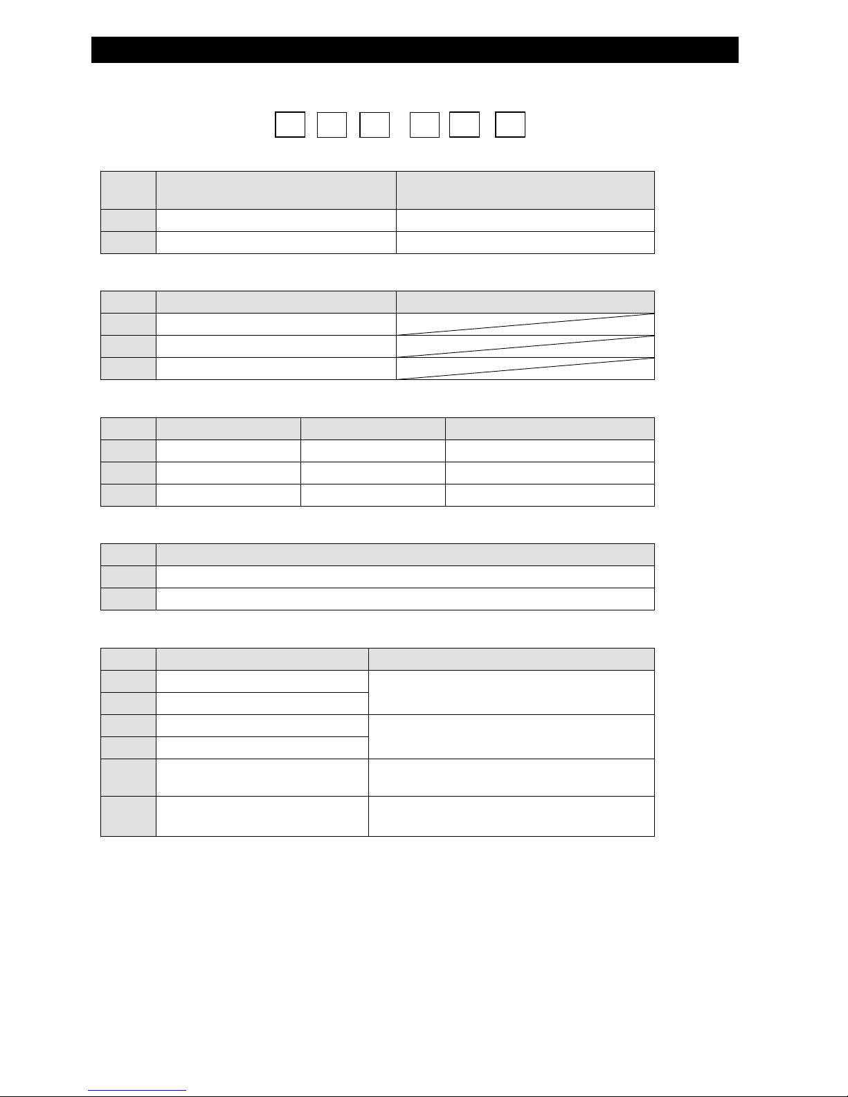
■ OUT LINE TESTER MODEL
MODEL
FL-
2
① MODEL
Symbol Permissive Leak rangeApplication Application
8
±0.01~9.99 kPa
Middle Leak Detection
9
±1~999 Pa
Small Leak Detection
② CALIBRATOR (BUILT IN)
Symbol With/Without Calibrator Remarks
6 Without Calibrator
6A 1.0ml Calibrator
6B 0.1ml Calibrator
③ SET PRESSURE RANGE
Symbol
TEST PRESSURE RANGE SET PRESSURE RANGE DISPLAY PRESSURE RANGE
UL
-10.0~10.0kPa -10.0~10.0kPa -10.0~10.0kPa
L
-100~200kPa -100~200kPa -100~200kPa
H
-100~900kPa -100~900kPa -100~900kPa
④ POWER SUPPLY
Symbol POWER SUPPLY
0
AC100V ±10% 50/60Hz
2
AC90~110V AC200~240V 50/60Hz
⑤ INTERNAL OPTIONS
Symbol OPTION REMARKS
R RS-232C Output
Select either RS-232C output (R) or printer
output (P).
P Printer Output
B1 Special Buzzer Sounding
Select either a “Beep” (B1) or a pulsed tone (B2)
for notification.
B2 Special Buzzer Sounding
E
Piping modification to correspond with
the external exhaust unit
Only for use with a vacuum
V
Manual valve position indication
switch
Only at work side
⑥ EXTERNAL OPTIONS see page 9.
① ② ③-④ ⑤ ⑥

7
TESTER SPECIFICATIONS
■ PERFORMANCE SPECIFICATIONS
◆ Testing Method: Differential Pressure Comparison
◆ Leak Pressure Range・Measurement Accuracy
MODEL
Leak Pressure Measurement
Range
Measurement Sensor Accurac
y
(Including hysteresis)
FL-286
±0.01~9.99kPa ±5%F.S.(10.00kPa)
FL-296
±1~999Pa ±5%F.S.(1000Pa)
Direct Pressure Sensor Accuracy
MODEL Pressure Measurement Range
Measurement Sensor Accurac
y
(Including hysteresis)
UL
-10.0~10.0kPa ±5%F.S.(-10.0kPa、10.0kPa)
L
-100~200kPa ±5%F.S.(-100kPa、200kPa)
H
-100~900kPa ±5%F.S.(-100kPa、900kPa)
■ FUNCTION SPECIFICATIONS
Timer Setting Range
DLY
CHG
BAL
DET
EXH
(Delay)
(Charge)
(Balance)
(Detection)
(Exhaust)
0.0 ~ 999.9sec
0.1 ~ 999.9sec
0.1 ~ 999.9sec
0.1 ~ 999.9sec
0.2 ~ 999.9sec
Group Setting Function
4ch(DLY time, CHG time, BAL time, DET time, EXH time, -NG set,
+NG set, -NG set(leak amount), +NG set(leak amout), P.NG value,
Volume value, -NG unit (leak amount), +NG unit(leak amount),
Volume unit, Leak amout indication unit)
Supplemental Functions
BUBL(Bubble),CAL(Calibration), Cylinder Control
Test circuit internal volume
8 ml(when rear panel stop valve is closed)
Display Digital indication in four digi
t
External Input/Output
1. Contact input/output for control 38
P
2. Option input/output
・Output for printer(Centronics-compliant output system)
・RS-232C input/output with PC
■GENERAL SPECIFICATIONS
Operation Temperature Range
0~40℃
Operation Humidity Range
35~85%RH(without condensation)
Power Source
A
C100V±10% 50/60Hz
AC90~110V AC200~240V 50/60Hz
Power Consumption 150VA
Voltage enduranc
e
A
C1000V 1 minut
e
Insulating Resistance More than 50MΩ at DC500V
Leak Current Less than 1mA at AC100V
Pressure enduranc
e
UL Range:-50~+50kPa、L Range:-100~+600kPa、H Range:-0.1~+1.5MPa
Dimensions Function
W172.9 mm×H272.8 mm×D386 mm(Without external option)
Weight
Power Source100V:About 9.5 kg
Power Source 200V:About 10.5 kg
Air Specifications
Please supply clean , stable , and dry air
Recommended Condition: Based on JISB8392-1:2000
Compressed Air Quality Class1,3,1
Class
A
rticle Referenc
e
1 Maximum Particle Diameter
0.1μm
3
Minimum Pressure Dew-point
-20℃
1 Maximum Oil Conten
t
0.01mg/
m
3
8
OUTLINE DO YOU HAVE EVERYTHING ?
■ DO YOU HAVE EVERYTHING?
Confirm the following points prior to operating the tester. If there are any problems such as incorrect
specifications, missing accessory parts or damages with the delivered items, please contact your FUKUDA agent.
Please compare the model numbers described below with the number indicated on the tester’s nameplate.
Please specify the SER (serial number) when contacting your FUKUDA agent.
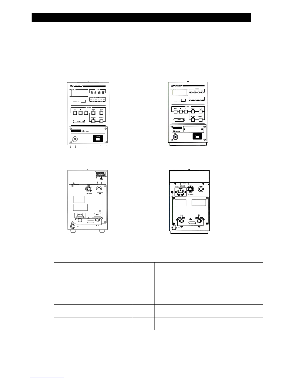
○ TESTER STRUCTURE
【FL-2□□□-0 FRONT】 【FL-2□□□-2 FRONT】
【FL-2□□□-0 REAR】 【FL-2□□□-2 REAR】
○ STANDARD ACCESSORIES
A
CCESSORIES
NUMBER
REMARKS
AC POWER CODE 1.5m 1
A
s the attached AC power cord is of Japanese
domestic specification (rating 125V), if it does not fit to
the specifications of the using area or place, kindly
please prepare the suitable one by yourself.
A
DJUSTMENT SCREW DRIVER
1
MOUNTING BRACKET
1
FIXING SCREW M4×8L 4
OPERATION MANUAL
1
TEST DATA SHEET
1
Unit Stickers
1
9
OUTLINE OPTIONS
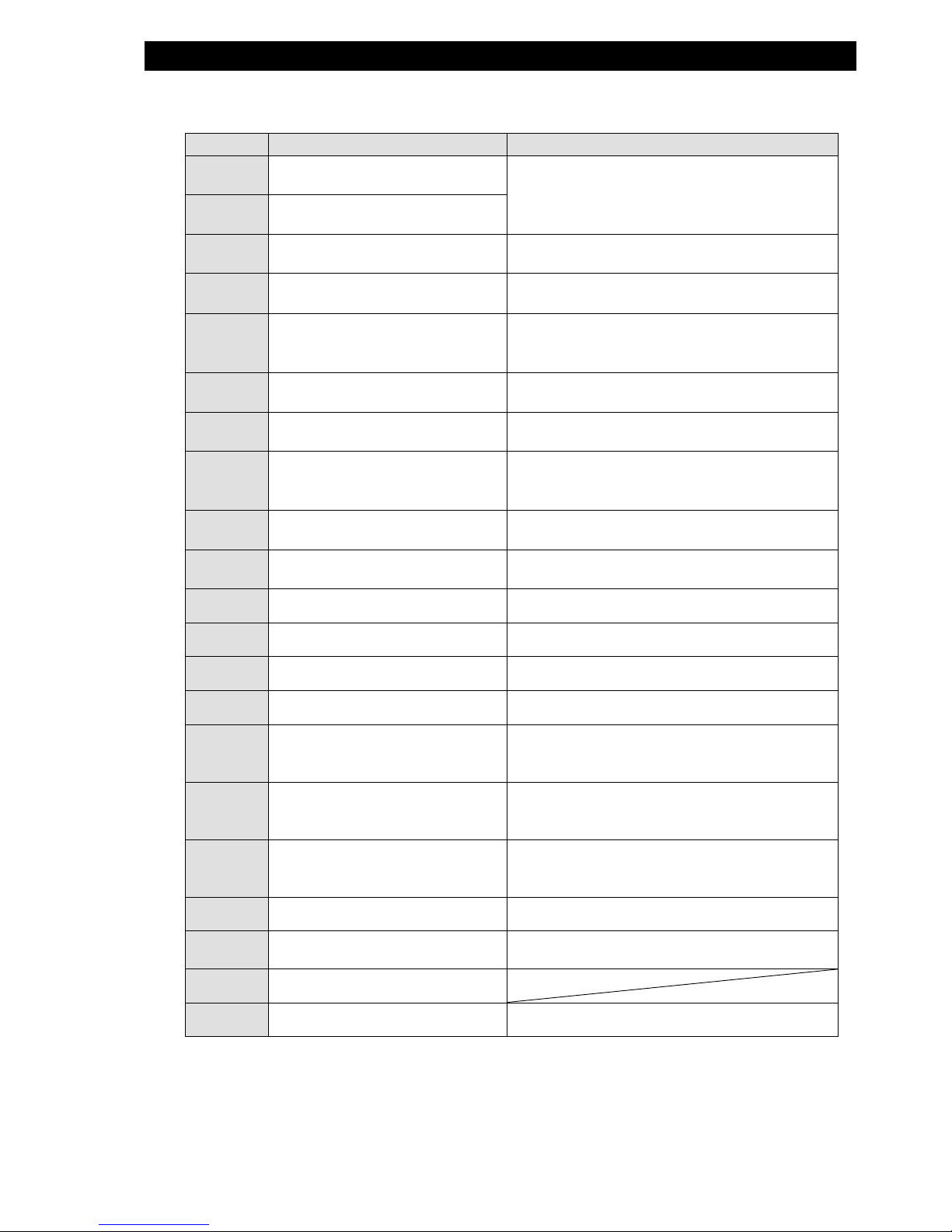
○ OPTION
⑥ EXTERNAL OPTIONS
MODEL COMMON OPTION REMARKS
C1
Manual Calibrator0.1mlF.S.
(Externa)
Mounted in the rear of the work port manual valve.
One of C1 or C3 is chosen.
C3
Manual Calibrator1.0mlF.S.
(External)
FR53 Filter/Regulator Unit
Positive Pressure Standard Spec.
Pressure Setting Range:0.02 ~ 0.2MPa
FR54 Filter/Regulator Unit
Positive Pressure Precision Spec。
Pressure Setting Range:0.005 ~ 0.2MPa
FR55 Filter/Regulator Unit
Positive Pressure Precision Spec.
+ High Performance Filter
Pressure Setting Range:0.005 ~ 0.2MPa
FR56 Filter/Regulator Unit
Positive Pressure Standard Spec.
Pressure Setting Range:0.05 ~ 0.85MPa
FR57 Filter/Regulator Unit
Positive Pressure Precision Spec.
Pressure Setting Range:0.005 ~ 0.8MPa
FR58 Filter/Regulator Unit
Positive Pressure Precision Spec.
+ High Performance Filter
Pressure Setting Range:0.005 ~ 0.8MPa
FR59 Filter/Regulator Unit
Positive Pressure Standard Spec.
Pressure Setting Range:0.1 ~ 1.6MPa
FR61 Filter/Regulator Unit
Negative Pressure Standard Spec.
Pressure Setting Range:-100 ~ -1.3kPa
FR62 Filter/Regulator Unit Negative Precision Spec. P-200
FE-20 External Exhaust Unit For Positive Pressure
FE-20C External Exhaust Unit For Positive Pressure with Drain
FE-20V External Exhaust Unit For Negative Pressure
PS-01 Pressure Switch
Small pressure switch for negative pressure,
Accuracy: ±3% F.S.
Pressure Setting Range:-101 ~ 0kPa (5~40℃)
PS-02 Pressure Switch
Small (low) pressure switch for positive pressure,
Accuracy: ±3% F.S.
Pressure Setting Range:0 ~ 100kPa (5~40℃)
PS-03 Pressure Switch
Small pressure switch for positive pressure,
Accuracy: ±3% F.S.
Pressure Setting Range:0 ~ 970kPa (5~40℃)
FP-100 Thermal Printer Print out measured data
CB-14 Manual Operation Box
One Circuit each for start and reset switch 4-group
switching function.
P-200 Pilot Regulator
R5 Regulator for small pressure
Pressure Setting Range:0.5 ~ 10kPa
※The high-performance filter consumes air at a rate of 0.3 m3/h.
INSTALLATION INSTRUCTIONS
■ INSTALLATION INSTRUCTIONS
Air leak testers detect leaks by reading out precise pressure (air condition) alterations.
Thus, it requires different handling instructions from other standard precision equipment.
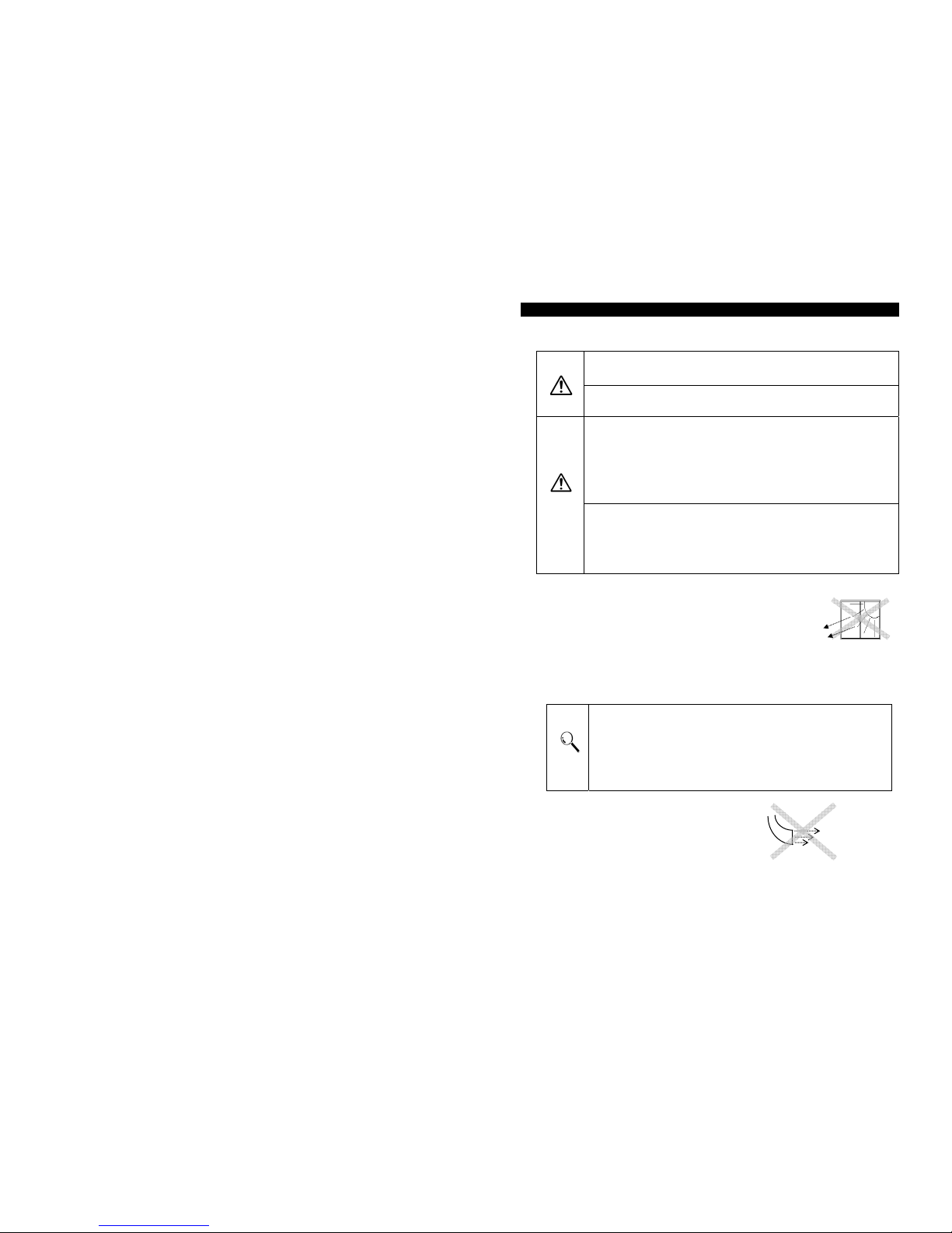
WARNING
Tester must be in a stable position.
・ Be sure to install the tester on a level surface.
Vibrations or earthquakes may cause the tester to fall and cause injury to operators.
Do notplace anything on top of the tester.
・Do not place anything on top of the tester. Falling objects may
result in injury.
CAUTION
Do not install the tester in the following locations:
・ High moisture or dusty areas.
・ Areas in which oil and water can cause contamination.
・ Areas directly exposed to sunlight.
・ Outdoors
May result in fire or electric shock.
・ Areas with obstructions or places in which the testers fanning
system may be blocked.
The tester may overheat and may cause for fires.
Moving the Tester:
・ Be sure to shut off the power, unplug cords, cut off the
pneumatic source and remove piping.
・ Be sure to carry the tester in a stable manner.
(Do not carry the tester by the manual valve handle.)
May cause damage to the tester or to its casing and may result in
injury
.
○ OPERATION ENVIRONMENT
FL-286,296
14
FL-286,296
• To keep the stable measurement condition, install the air
leak tester where it will not receive any influences from
temperature or humidity changes, such as at the center of
the facility. Do not in stall the te ster n ear wi ndows or
an area that is directly exposed to the sunlight. The
operation temperature and humidity is as follows.
Ambient Temperature: 0~40℃
Ambient Humidity: 35~85%RH with no condensation.
• In order to attain best results and accuracy, it is re commended that the operation
temperature and environment humidity condition is 23 ±5℃, 55±10%RH.
• Rapid temperature change adds the noise on the measurement and specified
performance cannot be obtained.
• Transferring the tester rapidly from high to low temperature locations and/or
humidity points may cause condensation. When such cases cannot be avoided,
leave the tester in the environment for at least an hour in order for it to adjust to
the surrounding temperature.
• Environment
Temperature change is the enemy of leak test. Avoid
the direct sun shine or the wind from outside on
work, master and measurement piping. Also be
careful against the wind from air conditioner
(heating/cooling) duct or the entrance.
Warning
FL-286,29
6
1
5
INSTALLATION INSTRUCTIONS
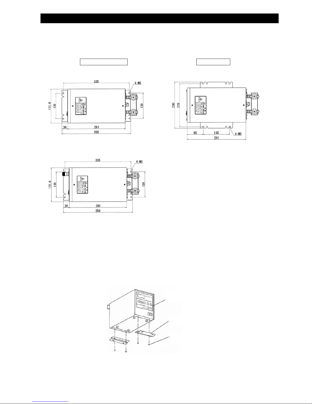
● INSTALLATION LAYOUT
z Use a pair of brackets and the supplied screws.
※Dimensions in front & in the rear differ in case Manual Calibrator is mounted, or not.
●
INSTALLATION MEASURMENT
Follow the remarks listed below for installation.
Leave a sufficient amount of space in the rear for the work connection cables and
pressurized air piping.
See page 72 and page 74 for external dimensions.
● Fixing the Brackets
Example of Front/Rear Fixing
Fix the brackets using the screws into the tapped holes on the bottom of the unit.
Front/Rear Mounting Side Mounting
・Without calibrator
・With calibrator
・Both with and without calibrator
Main body
Supplied Screw
Mounting bracket
1
6
AIR PIPE CONFIGURATIONS
☆ Air leak testers are designed to detect a leak by sensing a small change in pressure.
For that reason, you must ensure that the air leak tester’s piping differs from normal piping.
Please keep this in mind to help obtain accurate and reliable leak testing.
☆
TEST CIRCUIT PIPES
For the test circuit piping, it is necessary to use rigid, leakless pipes that will not change in size and
configuration under applied pressure.
For connection, use a high-pressure type coupler.
Arrange them to minimize thermal effect.
Keep them away from heat generating elements such as solenoid valves.
Keep the piping arrangement as short as possible.
Wrap them with thermal insulation material.
(e.g. Spiral Tubes)
Others
Stabilize the piping to avoid unnecessary movements during measurement.
Allow “MASTER” and “WORK” piping to provide the same conditions.
Do not connect inappropriate items to the testing piping.
Make sure you always use the optional pressure switch which checks the internal
pressure of the work, if the equipment is used with a pressure of 10 kPa or lower.
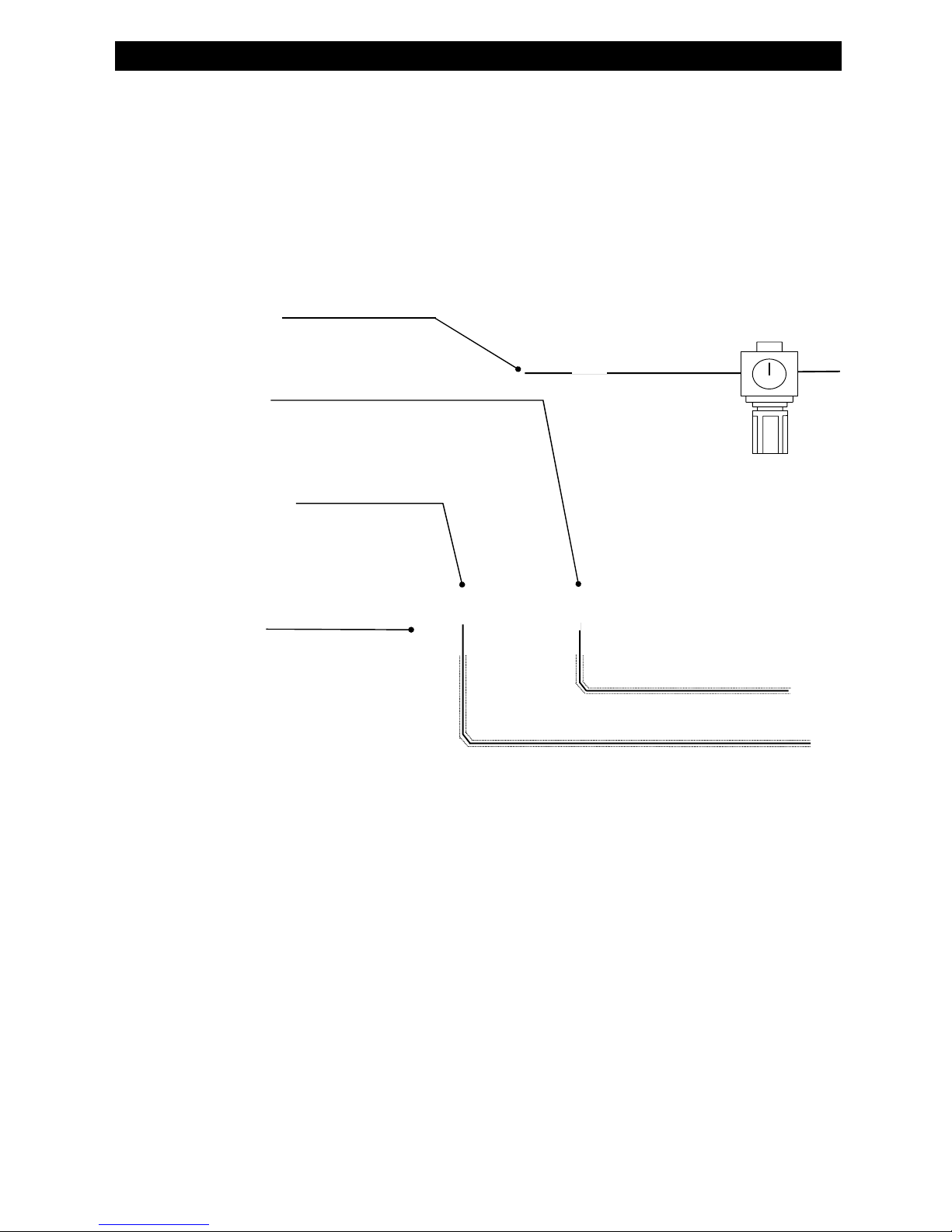
PRIMARY PRESSURE
REGULATOR
Adjust to: (approx.)
Test pressur
e
+100kPa
Pressure Supply Port
(AIR SUPPLY)
Rc 1/4
Work Port
(WORK)
Rc 1/4
Connect to a work (WORK)
This is a measurement pipe.
Master Port(MASTER)
Rc 1/4
Connect to a master.
This is a measurement pipe.
Exhaust Port
(EXH)
Rc 1/4
AIR PIPING CONFIGURATION
17
IN CASE OF WATER/OIL INTRUSION IN WORK
Oil, water or chippings may intrude in works
because of the previous process.
The tester may draw in unwanted objects
during the exhausting process, and may cause
possible break down.
Install the external exhaust unit (optional) within
the testing air circuit.
While the FE-20 optional external exhaust unit
is in use, close the exhaust port of the air leak tester
with the attached plug.
FE-20
FE-20C
FE-20
V
空圧源
供給エアーにはクリーンなものを御使用下さい。
エアリークテスターのセンサーにとって、油分・水分は大敵です。
エアフィルターはもちろん、必要に応じエアドライヤなどの空気清浄器を設備して
下さい。
またルブリケータを使用する時は、エアリークテスターへの供給配管と主配管から
クランプ装置
シリンダー駆動圧力を調整する減圧弁は、個別に設けて下さい。
シリンダーが動作する時の圧力変動が、エアリークテスターへの圧力供給を変動
させたり、他軸のシリンダーのクランプ力を変動させ、測定を不安定にする事が
あります。
漏れ測定部(ワーク、マスター)の内容積は、
測定感度を上げる為、配管を短くしたり、中子
等を利用して出来るだけ小さくして下さい。
Position close to the
Work parts.
主配管
マスターを御用意下さい。
漏れ測定を行う時は、マスターを取り付けて下さい。マスターの容積・形状・接続方法によ
り、漏れ測定の精度が変化します。マスターは、ワークと同一形状・同材質・同一の配管・
同一取付が望ましいのですが、実際の設備では全てを満たす事はなかなか出来ません。
マスター設置の際のポイントを以下に示します。
項 目 上 策 次 善 策
マスター
漏れの無いワーク
(ワーク側と同じ条件にする)
ワーク側より小さめの剛体タンク
(早く安定になるようにする)
取付位置
ワークの近くで同じ高さにする ワーク側と高さを同じにして周囲を囲う
(同じ温度で変動が無いようにする)
配管
ワーク配管と一緒にして平面に這わ
せる
ワーク側と長さを同じにする
(温度影響があるときは短くする)
手待ちワークの温度が変化
しないように、リークテス
ト装置の近くで同じ高さの
場所に保管して下さい。
クランプシリンダー
Master
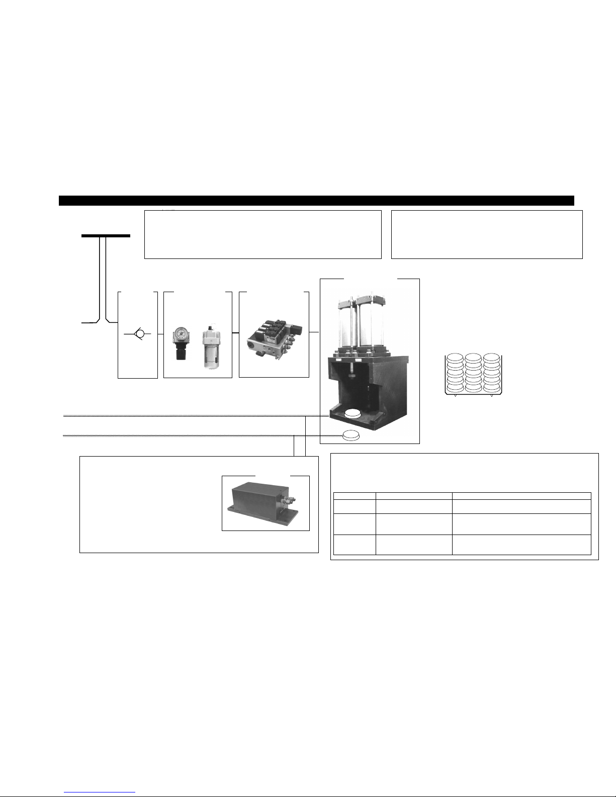
COMPRESSED AIR SOURCE:
Water and oil intrusion often cause the pressure sensor in the air leak tester to malfunction. Be
sure to provide an air filter, and if necessary, equip an air purifier such as an air dryer.
Furthermore, it is important to contrive a bypass air piping system when using lubricator so that
lubricating oil will not intrude the tester
CLAMPING EQUIPMENT
Regulators to adjust the cylinder driving pressure must be provided separately
for each cylinder. This minimizes the possibility of cylinder movement, which
destabilizes the pressure supply to the air leak tester. Supplied air pressure
fluctuation may interfere with the clamping powers of the other cylinders
Main air source
制御用電磁弁
逆止め弁
Check Valve
Regulator
Lubricator
Sol. Valve for control
Clamp Cylinder
KEEPING THE INTERNAL VOLUME AS SMALL AS
POSSIBLE
In order to increase test sensitivity, keep the internal volume of
the work and master parts as small as possible. Shortening
pipes or using a core is ways to decrease internal capacity.
AVOID TEMPERATURE CHANGE
In order to avoid temperature
interference to work parts waiting to
be tested, keep them close to leak
tester and at about the same level.
PREPARE THE MASTER PARTS
It is recommended to use master (criterion) parts for air leak testing. Leak testing accuracy will change according
to the status of the applied master parts, so it would be ideal to use master parts equivalent to the work parts in
shape, material, piping and mounting. Maintaining these conditions can be difficult in actual settings. Please
refer to the following chart when choosing a master part.
Best Method
A
lternative
Master
・Test Parts with no leak
(same conditions as the work)
・A rigid tank that has a slightly smaller volume than that
of the work (to stabilize quickly)
Mounting
Position
・Same height from the ground
as the work
・Near the work
・Same height as the work and surround the peripheral
・Environment with the same temperature interference
conditions as the work parts
Piping
Arrangement
・Same conditions and
arrangement as the work piping
and arrange piping in plane .
・Same piping length as the work port (shorter when there is
temperature interference)
ELECTRIC WIRING CONFIGURATION
● ELECTRIC WIRING PRECAUTIONS
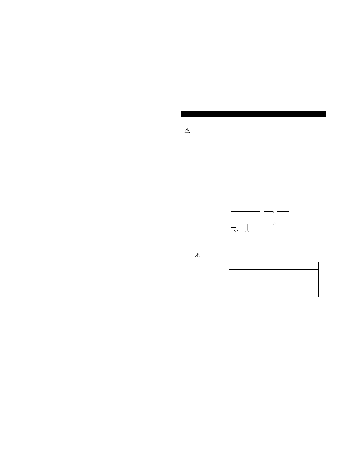
EXAMPLE
(AC 200V/100V step-down transformer is used for an air leak tester with AC 100V spec)
Air Leak Tester
MODEL
AC100V AC110V AC200V
FL-2□□□-0 FL-2□□□-2
POWER LINEVOLTAGE
AC100V±10%
50/60 Hz
AC90~110V
50/60 Hz
AC200~240V
50/60 Hz
※ Power consumption increases if valves and other parts are driven by an external control.
18
AC100V
BEFORE WIRING AIR LEAK TESTER, BE SURE TO TURN OFF THE MAIN POWER
SWITCH. (Unplu
g
the tester from the AC power source)
Insulated Transformer
AIR LEAK TESTER with AC100V
Supply line voltage suitable to the power line voltage of the tester.
● Select appropriate wires and material according to use, considering voltage and current
requirements for each of the terminal outlets located on the rear panel of the tester.
● To avoid noise interference, run the input signal lines separately (pins #1 to #12 of the Terminal Board)
from the output signal lines.
● To avoid noise interference, run the input signal lines separately from other power supply lines.
● To avoid noise interference, it is recommended to use a shield wired for input signal lines.
● Be sure to ground the frame grounding (pins #37 and #38 of Terminal Board).
● Use an insulated transformer when the power for the tester is supplied through a step-down
transformer.
AC200V
AC100V L
AC100V N
F.G.
○
○
ELECTRIC WIRING CONFIGURATION
Control testing and bubble testing procedures
・ START Start of air leak test.
Applies a pulse signal of 0.5 sec or longer during DLY sequence.
・BUBL Start of bubble test
Performs a bubble test while a signal is being applied.
・RESET Stop the tester in case of an emergency.
Apply a break signal to open the air circuit. The RDY sequence
is established after EXH sequence.
Test result output
・OK -NG set range < leak reange < +NG set range
・+NG leak reange ≧ +NG set range
・-NG -NG set range ≧ leak reange
・P.NG Test pressure is lower than the set value at the end of
PRES sequence.
・P.NG Test pressure is lower than the set value set up with
P.SW at time of BAL sequence.
Current status output
・RDY Standby (Ready Status)
・ERR Error has transpired.
When the power is OFF, ERR can be used to confirm
ON/OFF status.
・END Testing has ended.
*1 The air leak tester’s internal output status: power off.
*2 The names, indicated with line(***)imply that the signal is effective when it is open. 19
Controlling clamping cylinders
・LMT 1 Input of unclamp signals
・LMT 2 Input of clamp signals
・SOL 1 Cylinder Driving valve control signals
※
In the Internal Operation Mode, the tester cannot operate.
Specifies the Group # (0~3)
・ CH1
・ CH2
Group # selection
0 1 2 3
CH1 ○ ● ○ ●
CH2 ○ ○ ● ●
○:Open ●:Short
Controls the exhaust bypass unit
SUPPLIES POWER TO THE AIR LEAK TESTER
Apply power voltage specified by the manufacture
・F.G Be sure to ground this terminal.
EXHAUST BYPASS UNIT CONTROL SIGNALS
POWER SUPPLY
GROUP SWITCHING SIGNALS
CYLINDER CONTROL SIGNALS
Pressure Error (P.NG) Verification Signal Input
・P.SW Pressure switch signal input.
If pressure verification function is not used,
keep the P.SW pin connected to the COM- pin.
PRESSURE VERIFICATION SIGNALS
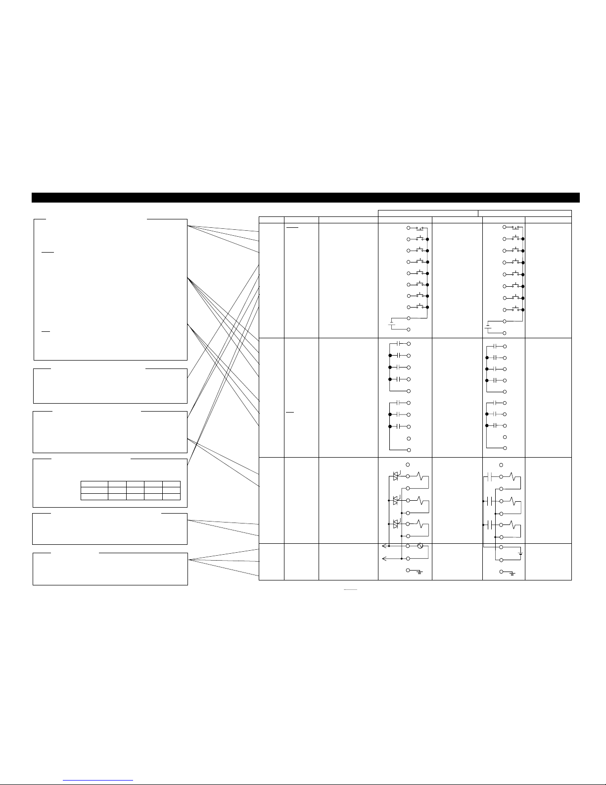
AIR LEAK TESTER CONTROL SIGNAL
z REMOTE TERMINAL BOARD
FL-
2
□□□-0 FL-2□□□-
2No
Cod
e
Meanin
g
Connection *1 Specification Connection *1 Specification
1
2
3
4
5
6
7
8
9・10
11・12
RESET
START
BUBL
P.SW
LMT1
LMT2
CH1
CH2
COMCOM+
Reset signal
Measurement start signal
Bubble test
Pressure verification
Unclamp verification
Clamp verification
Group # switch
Group # switch
Input signal common
Power sup. for pres. switch
Input signal
(Photo coupler)
・Voltage when open
DC 12V type
・ Voltage when
shorted
5 mA type
COM+Power
Supply
・Output voltage
DC 12V type
・Output current
50 mA min
Input signal
(Photo coupler)
・ Voltage when
open
DC 12V type
・ Voltage when
shorted
5 mA type
COM+Power
Supply
・Output voltage
DC 12V type
・Output current
50 mA min
13
14
15
16
17・18
19
20
21
22
23・24
OK
+NG
-NG
P.NG
COM O
1
RDY
ERR
END
-
COM O
2
OK results output
+NG result output
-NG result output
Pressure malfunction. Output
Output signal common 1
Stand by (Ready) output
Error output
End output
Unconnected
Output signal common2
Output signal
(Relay contact)
・Rated load
AC 250V 0.4A
DC 30V 0.4A
Output signal
(Relay contact)
・Rated load
AC 250V 0.4A
DC 30V 0.4A
25・26
27
28
29
30
31
32
-
SOL1
SOL1
SOL2
SOL2
SOL3
SOL3
Unconnected
Cylinder drive valve output
Pressure valve output
Optional valve output
Output signal
(SSR)
・Output Voltage
Power source
supply
・Actual ON current
1.0 Arms
・Leak current
3 mA max
Output si
g
nal
(Relay contact)
・Rated load
AC 250V 1A
DC 30V 1A
To accord with
external supply
power source specs.
33・34
35・36
37・38
AC
AC
F.G.
AC power input
AC power input
Frame Ground
Power source for
tester
AC100V±10%
50/60Hz
(Used also as external
valve power source)
Power source for
external valve
AC100V
DC24V
(Power source for
tester is inlet.)
 Loading...