

Page 1
OPTIONAL PART
Wireless LAN adapter
DESIGN & TECHNICAL MANUAL
WIRELESS LAN
ADAPTER
UTY-TFNXZ1
UTY-TFNXZ2
UTY-TFNXZ3
UTY-TFNXZ4
DR_OP001EX_03
2018.04.26
Page 2
Notices:
• Product specifications and design are subject to change without notice for future improvement.
• For further details, please check with our authorized dealer.
Trademarks
The following term and logo are trademarks of Fujitsu General Limited in the United States, other countries
or both:
FGLair
Android™ and Google Play™ are trademarks of Google Inc.
App Store® is a service mark of Apple Inc., registered in the U.S. and other countries.
IOS® is a trademark or registered trademark of Cisco in the U.S. and other countries and is used under
license.
™
Copyright © 2016, 2018 Fujitsu General Limited. All rights reserved.
Page 3

CONTENTS
WIRELESS LAN ADAPTER..................................................................1
1. Applicable indoor units ................................................................................2
2. Model lineup ..................................................................................................3
3. Overview ........................................................................................................4
3-1. Wireless LAN control .......................................................................................................5
4. Specifications................................................................................................7
4-1. Wireless LAN adapter......................................................................................................7
5. Wiring design ................................................................................................8
5-1. System diagram...............................................................................................................8
6. Installation ...................................................................................................10
6-1. Precautions....................................................................................................................10
6-2. Installation procedure.....................................................................................................11
7. Initial setup ..................................................................................................12
7-1. Mobile app installation and user registration ..................................................................12
7-2. Air conditioner registration .............................................................................................12
8. Accessories .................................................................................................13
Page 4

Page 5

WIRELESS LAN ADAPTER
MODEL NAME:
UTY-TFNXZ1
UTY-TFNXZ2
UTY-TFNXZ3
UTY-TFNXZ4
Page 6
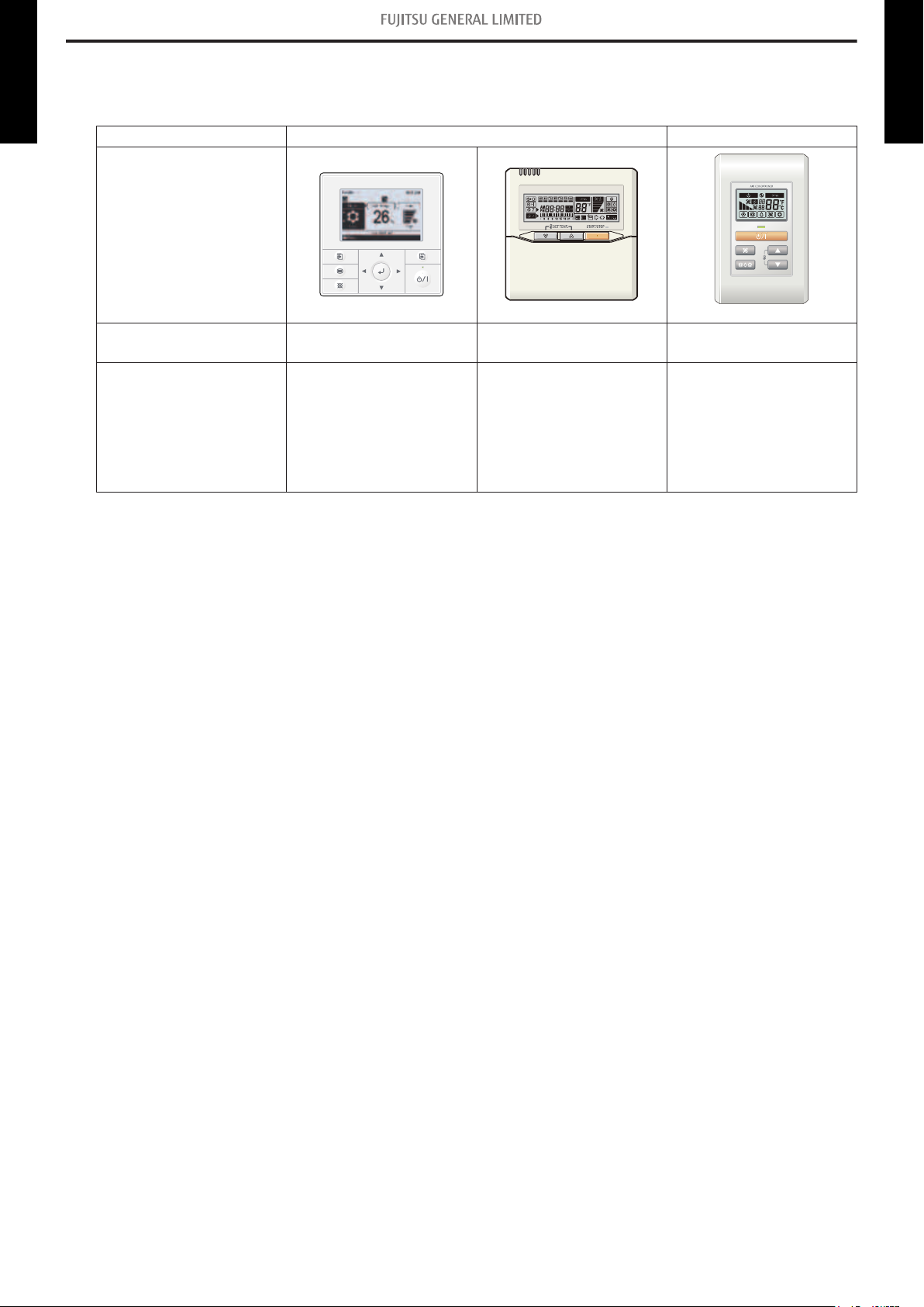
1. Applicable indoor units
This product is connectable to indoor units that following wired remote controllers can be connected.
Wireless LAN adapter
UTY-TFNXZ1-4
Remote controller type Wired remote controller Simple remote controller
**: Alphanumeric characters are printed on the product.
For details on applicable indoor units, refer to the product catalogue posted on “Support & Down-
loads” page of the web site.
http://www.fujitsu-general.com/global/support/
Exterior
Model name
(Accessory)
Model name
(Option)
AR-WDC1E
AR-WDD1E
UTY-RVNYM
UTY-RVNYN
UTY-RVNUM
UTY-RVNGM
UTY-RVNXM
AR-6TC**
AR-WAE**
UTY-RNNYM
UTY-RNNYN
UTY-RNNUM
UTY-RNNGM
UTB-GUD
UTY-RNNXM
AR-WAF**
UTY-RSNYM
UTY-RSNYN
UTY-RSNUM
UTY-RSNGM
UTY-RSNXM
UTY-TFNXZ1-4
Wireless LAN adapter
NOTE: Combined use of WLAN adapter and wired remote controller is prohibited.
- 2 -
1. Applicable indoor units
Page 7

2. Model lineup
Wireless LAN adapter
UTY-TFNXZ1-4
Model name Region or country
UTY-TFNXZ1 Europe
UTY-TFNXZ2 North America, Middle East
UTY-TFNXZ3 Oceania, Thailand, Vietnam, India
UTY-TFNXZ4 China
UTY-TFNXZ1-4
Wireless LAN adapter
- 3 -
2. Model lineup
Page 8

3. Overview
a
b
c
Indoor unit
WLAN adapter
Wireless LAN router
Smart device
Smart device
Internet
Wireless LAN adapter
UTY-TFNXZ1-4
a LED 1 (green)
Operation status indicator.
b LED 2 (orange)
Wireless LAN status indicator.
c Setting button
Used for connecting to wireless router.
UTY-TFNXZ1-4
Wireless LAN adapter
Schematic diagram:
- 4 -
3. Overview
Page 9

3-1. Wireless LAN control
By installing FGLair on a smart device, several functions can be controlled from outside the house.
Wireless LAN adapter
UTY-TFNXZ1-4
CAUTION
To prevent personal injury, property damage, or product malfunction, read the setting manual attached with the product carefully, and be sure to comply with the safety and usage precautions.
¢ Easy setup by mobile application
Initial setup can be done by using FGLair.
Refer to the setting manual attached with the product for information on the initial setup, operat-
ing tips, and troubleshooting.
System requirement
¢
Before using this function, prepare the following items:
• Wireless router:
Wireless LAN standard IEEE802.11b/g/n
Frequency bands*
Network security standard
• U.S.A., Canada: 2.4 GHz (1ch—11ch)
• Other countries: 2.4 GHz (1ch—13ch)
• Open
• WEP
• WPA (PSK)
• WPA2 Personal (PSK)
• WPS for same-LAN registration
Wireless LAN adapter
UTY-TFNXZ1-4
*: Usable only in the country or region where you purchased the product.
To check whether your wireless router complies with the network security standards listed above,
refer to the operation manual.
• Smartphone or Tablet PC:
App-compliant operating
system
®
iOS
Android
™
Version 8.0 or later
Version 4.1 or later
• (mobile application):
Mobile app is available on Google Play™ store or on App Store®.
After installation of mobile app, user registration is required. For user registration and setup infor-
mation, refer to Setting Manual attached with the product.
For the latest version of the Wireless LAN (WLAN) control manuals, refer to the following web site.
https://www.fujitsu-general.com/global/support/
3-1. Wireless LAN control 3. Overview
- 5 -
Page 10

Wireless LAN function list
¢
NOTE: To use Wireless LAN control, user registration in advance and access to the wireless home
Wireless LAN adapter
UTY-TFNXZ1-4
Air conditioning control
function
Additional function ECONOMY operation setting ○
App function Air conditioner error e-mail notification ○
Zone setting
network are required.
Operation on/off ○
Operation mode setting ○
Set temperature setting ○
Fan speed setting ○
Airflow direction setting
Timer setting
Zone setting (on/off) ○
*2
Room temperature sensor setting
Weekly timer with zone ○
Name setting (zone/sensor) ○
Item Mobile app
Louver position adjustment
*1
(vertical/horizontal)
○
Swing (vertical/horizontal) ○
Off timer —
On timer —
Sleep timer —
On/off program timer —
Weekly timer ○
*3
○
Wireless LAN adapter
UTY-TFNXZ1-4
○: Available, —: Not available
*1: Different by the indoor unit function.
*2: Available only for duct models and UTY-TFNXZ3 in Australia.
*3: UTY-XSZX is necessary.
3-1. Wireless LAN control 3. Overview
- 6 -
Page 11

4. Specifications
Top view
Unit: mm (in)
Top view Side view
38 (1-1/2)
15 (9/16)
71 (2-15/16)
96 (3-3/4)
12.5
(1/2)
12.5
(1/2)
Wireless LAN adapter
4-1. Wireless LAN adapter
UTY-TFNXZ1-4
Wireless LAN adapter
UTY-TFNXZ1-4
Maximum radio-frequency power mW 32
mm 71 × 38 × 15
in 2-15/16 × 1-1/2 × 9/16
mm 50 × 207 × 138.5
in 1-15/16 × 8-1/8 × 5-7/16
g (oz)
35 (1) (without cable)
Dimensions
(H × W × D)
Weight
Net
Gross
Net
Gross 380 (13)
Operating temperature range °C (°F) 0 to 46 (32 to 114.8)
4-1. Wireless LAN adapter 4. Specifications
- 7 -
Page 12

5. Wiring design
Indoor unit
Outdoor unit
WLAN adapter
Indoor unit
Outdoor unit
WLAN adapter
Indoor unit
WLAN adapter
Single system Multiple system
ABC
Indoor unit
Zone control interface
Outdoor unit
WLAN adapter
A
Wireless LAN adapter
5-1. System diagram
UTY-TFNXZ1-4
One WLAN adapter can be connected to each indoor unit.
A, B, and C: Attached cable with this product.
NOTE:
Combined use with wired remote controller is prohibited.
Wireless LAN adapter
UTY-TFNXZ1-4
When using this product with Zone control interface:
NOTE:
For detailed wiring design of combined use with Zone control interface, refer to the Design
and Technical Manual for Zone control interface.
5-1. System diagram 5. Wiring design
- 8 -
Page 13

Prohibited uses:
Indoor unit
Indoor unit Indoor unit
Indoor unit Indoor unit
Outdoor unit
Indoor unit
Junction box
(1) Combined use with wired remote controller
Wireless LAN adapter
UTY-TFNXZ1-4
(3) Use in simultaneous multi system
(2) Group connection of indoor units
(4) Extended wiring
Extending the cable is prohibited.
Wireless LAN adapter
UTY-TFNXZ1-4
5-1. System diagram 5. Wiring design
- 9 -
Page 14

6. Installation
CAUTION
Wireless LAN adapter
UTY-TFNXZ1-4
To prevent personal injury, property damage, or product malfunction, read the setting manual attached with the product carefully, and be sure to comply with the safety precautions.
6-1. Precautions
CAUTION
• Do not bundle the WLAN adapter wiring with the connection cable running between the indoor
and outdoor units, or the power supply cable.
• Install the WLAN adapter near the wireless router. (The connection will become unstable if it is
placed further away, which will make using the system more difficult.)
• Install the WLAN adapter between the indoor unit and wireless router.
• Certain types of wall materials may shut out wireless communications.
• Do not touch the indoor unit heat exchanger.
• During installation or removal, do not to have the wire caught by any parts nor pull it hard. It may
result in malfunction of the air conditioner.
• Do not install this product in following places. Otherwise, radio communication may be interfered.
– Places exposed to direct sunlight
– Places subject to extremely high and low temperatures, such as near the outlet port of the air
– Near the air conditioner air inlet or outlet
– Places with high humidity
– Places near moving parts of the air conditioner main body
– Places near bottom of the air conditioner main body
– Inside or on the side of the air conditioner main body
– Near microwave ovens
– Within 1 m (40 in) of a TV or radio
– Places in the reach of children
– Near automatic control devices such as automatic door sensors or fire detectors
– Places with oil, vapor or flammable gases
– Near medical equipment, pacemakers, defibrillators or other devices
– Places where the WLAN adapter could get wet, such as in the bathroom
– Places where the WLAN adapter is difficult to access for maintenance
• Install this product in a place where the switches and buttons can be operated and where the
LED display can be confirmed. (In the areas as shown below.)
conditioner main body
UTY-TFNXZ1-4
Wireless LAN adapter
6-1. Precautions 6. Installation
- 10 -
Page 15

6-2. Installation procedure
Tapping screws
(Accessories)
GOOD
PROHIBITED
Reverse direction On a curved surface
On the floor
WARNING
Wireless LAN adapter
UTY-TFNXZ1-4
• Disconnect the power supply or turn off the breaker before starting work. Failure to disconnect
the power supply may lead to electric shock or fire.
• Do not turn on the power until all installation work is complete.
• Use the accessories or specified connection cables:
– Do not modify connection cables other than those specified.
– Do not use extension cords.
– Do not use independent blanch wiring. The allowable current will be exceeded and cause
• When installing this product, make sure that there are no children nearby. Otherwise, injury or
electric shock could result.
CAUTION
• Discharge static electricity on your body before starting work. If static electricity is not discharged, there is a risk that the circuit board components may be damaged.
• When performing wiring work, be careful not to damage the cable or injure yourself. Also, connect the connectors securely. Loose connectors will cause trouble, heating, fire, or electric
shock.
• Perform wiring so that water does not inter this unit along the external wiring. Always install a
trap to the wiring or take other countermeasures. Otherwise, it will cause trouble or electric
shock or fire.
• Do not touch the circuit board and circuit board parts directly with your hands. Otherwise, injury
or electric shock could result.
electric shock or fire.
UTY-TFNXZ1-4
Wireless LAN adapter
1. With referring the setting manual, perform wire connection.
2. Install the WLAN adapter in the direction as shown in this figure. If the WLAN adapter is installed in the wrong direction, water may get into the adapter through the wire, causing failure.
After WLAN adapter installation is completed, perform appropriate function setting according to the
installation environment with referring the setting manual of this product and the installation manual
of the indoor unit.
6-2. Installation procedure 6. Installation
- 11 -
Page 16

7. Initial setup
By using FGLair, perform initial setup for WLAN control.
Wireless LAN adapter
UTY-TFNXZ1-4
NOTE: Make sure that the smart device is connected to the same wireless router that the WLAN
7-1. Mobile app installation and user registration
1. Visit Google Play store or App Store according to the type of connecting smart device.
2. Search for FGLair in the store.
3. Install the app by following the on-screen instructions.
4. After completing FGLair installation on your smart device, open the app and perform user regis-
7-2. Air conditioner registration
Prerequisite:
Make sure that the smart device is connected to the same wireless router that the WLAN adapter is
connected.
1. Launch FGLair on your smart device.
2. Follow the instructions written in the setting manual attached with this product.
adapter is connected.
tration by following the instructions.
UTY-TFNXZ1-4
Wireless LAN adapter
7-1. Mobile app installation and user registration 7. Initial setup
- 12 -
Page 17

8. Accessories
MAC:____________
SSID: AC-UTY-____________
PIN: ________
Important : Please do not discard.
Wireless LAN adapter
UTY-TFNXZ1-4
Setting manual 1
Part name Exterior Q’ty Part name Exterior Q’ty
Tapping screw
M4 × 25 mm
2
UTY-TFNXZ1-4
Wireless LAN adapter
Operating manual
(CD-ROM)*
*: Available only for UTY-TFNXZ1.
1 Wireless LAN label
1
- 13 -
8. Accessories
 Loading...