

Page 1

REMOTE CONTROLLER (WIRED TYPE)
UTY-RVNUM
PART No. 9380222057
INSTALLATION MANUAL
For authorized service personnel only.
MANUEL D'INSTALLATION
Pour le personnel agréé uniquement.
MANUAL DE INSTALACIÓN
Sólo para personal de mantenimiento autorizado.
English
FrançaisEspañol
Page 2

En-1
INSTALLATION MANUAL
PART No. 9380222057
REMOTE CONTROLLER (WIRED TYPE)
Contents
1. SAFETY PRECAUTIONS ...........................................................................1
2. ACCESSORIES ..........................................................................................2
3. ELECTRICAL REQUIREMENT .................................................................. 2
4. SELECTING AN INSTALLATION LOCATION
4.1. Dimensions .........................................................................................2
4.2. Name of parts .....................................................................................2
5. INSTALLING THE REMOTE CONTROLLER
5.1. Wiring ..................................................................................................3
5.2. Connection of remote controller cable ................................................3
5.3. Installation ...........................................................................................4
6. INSTALLATION METHODS
6.1. Group control ......................................................................................6
6.2. Dual remote controllers .......................................................................6
7. TURNING ON THE POWER ...................................................................... 6
8. INITIAL SETTING ....................................................................................... 6
9. SERVICE SCREEN SETTING
9.1. Test run ............................................................................................... 7
9.2. Function setting ..................................................................................7
9.3. Error history ........................................................................................8
9.4. I.U. address verication ......................................................................8
9.5. Version ................................................................................................8
10. SETTING THE ROOM TEMPERATURE DETECTION LOCATION ......... 8
11. MANAGEMENT FUNCTION
11.1. Password setting ...............................................................................9
11.2. Management setting .........................................................................9
12. OTHERS
12.1. Error code .......................................................................................10
1. SAFETY PRECAUTIONS
The “SAFETY PRECAUTIONS” indicated in the manual contain important •
information pertaining to your safety. Be sure to observe them.
For details of the operation methods, refer to the operating manual.•
Request the user to keep the manual on hand for future use, such as for •
relocating or repairing the unit.
WARNING
This mark indicates procedures which, if improperly
performed, might lead to the death or serious injury
of the user.
CAUTION
This mark indicates procedures which, if improperly
performed, might possibly result in personal harm to
the user, or damage to property.
WARNING
For the air conditioner to operate satisfactorily, install it as outlined in this
installation manual.
Do not turn on the power until all installation work is complete.
Perform electrical work by an authorized service personnel in accordance
with the installation manual and the electrical wiring regulations or implementation regulations of the country. Improper electric work will cause
electric shock or a re.
Perform installation work in accordance with the installation manual.
Request an authorized service personnel to perform installation work.
Do not install this unit by yourself. Improper installation will cause injury,
electric shock, re, etc.
In the event of a malfunction (burning smell, etc.), immediately stop
operation, turn off the electrical breaker, and consult authorized service
personnel.
WARNING
Do not install the unit in the following areas:
Do not install the unit near a source of heat, steam, or ammable gas.•
Area lled with mineral oil or containing a large amount of splashed oil •
or steam, such as a kitchen. It will deteriorate plastic parts, causing the
parts to fall or the unit to leak water.
Area that generates substances that adversely affect the equipment, •
such as sulfuric gas, chlorine gas, acid, or alkali. It will cause the copper pipes and brazed joints to corrode, which can cause refrigerant
leakage.
Area containing equipment that generates electromagnetic interference. •
It will cause the control system to malfunction, preventing the unit from
operating normally.
Area that can cause combustible gas to leak, contains suspended •
carbon bers or ammable dust, or volatile inammables such as paint
thinner or gasoline. If gas leaks and settles around the unit, it can cause
a re.
Install the unit in a well-ventilated place avoiding rains and direct •
sunlight.
Do not operate this unit when your hands are wet.
Touching the unit with wet hands will cause an electric shock.
If children may approach the unit, take preventive measures so that they
cannot reach the unit.
CAUTION
When detecting the room temperature using the remote controller, please
set up the remote controller according to the following conditions. If the
remote controller is not well set, the correct room temperature will not
be detected, and thus the abnormal conditions like “not cooled” or “not
heated” will occur even if the air-conditioner is running normally.
Locate where is not be affected by inow of •
outside air such as caused by opening and closing a door.
Locate where an average temperature for the •
room being air-conditioned will be sensed.
Do not locate directly exposed to the outlet air •
from the air conditioner.
Locate out of direct sunlight.•
Locate away from the inuence of other heat •
sources.
Temperature sensor
Do not touch the remote controller PC board and PC board parts directly
with your hands.
Do not wire the remote controller cable and the bus wire together with or
parallel to the connection cables, transmission cables, and power supply
cables of the indoor and outdoor units. It may cause erroneous operation.
When installing the bus wire near a source of electromagnetic waves, use
shielded wire.
Do not set the DIP switches, either on the air conditioner or the remote
controller, in any way other than indicated in this manual or the manual
that is supplied with the air conditioner. Doing so may result in an improper operation.
Do not touch the switches with sharp objects. Doing so will cause injury,
trouble, or electric shock.
Do not expose this unit directly to water. Doing so will cause trouble,
electric shock, or heating.
Do not set vessels containing a liquid on this unit. Doing so will cause
heating, re, or electric shock.
Dispose of the packing materials safely. Tear and dispose of the plastic
packing bags so that children cannot play with them. There is the danger
of suffocation if children play with the original plastic bags.
Page 3

En-2
2. ACCESSORIES
The following installation parts are supplied. Use them as required.
Name and Shape
Q’ty
Application
Installation manual
1
This manual
Operating manual
1
Instruction book for operation
Remote controller cable
1
For connecting the remote controller
Connecting cable
1
For connecting the remote controller
cable to the wall mounted type and
the oor type indoor unit
Screw
(M4 × 16 mm)
2
For installing the remote controller
Cable tie
1
For remote controller and remote
controller cable binding
Screw
(M4 × 14 mm)
1
For installing the remote controller
cable to the indoor unit
Cable clamper
1
For installing the remote controller
cable to the indoor unit
3. ELECTRICAL REQUIREMENT
When connecting the remote controller, use cable specied as follows:
Conductor size Type Remarks
Remote controller
cable
0.33 mm
2
(22AWG)
Polar 3 core
Use sheathed
PVC cable
*We recommend that you purchase our service parts for the remote control-
ler cable. Contact service personnel to purchase this.
4. SELECTING AN INSTALLATION LOCATION
4.1. Dimensions
4-23/32 (120)
Unit: in. (mm)
4-23/32 (120)
1-25/32 (45.3)
2-16/32 (63.5)
19/32 (15.3)
3-9/32 (83.5)
6/32 (4.5)
6/32 (4.5)
16/32 (12.5)
7/32 (21.3)
1-6/32
(30)
11/32 (9)
1-10/32
(33.5)
6/32 (4.5)
29/32
(23)
4.2. Name of parts
CAUTION
Press the button lightly with a nger. It may cause a failure if pressed with
excessive force.
(1)
(2)
(3)
(4)
(5)
(6)
(7)
(8)
(9)
(1) Display panel (with backlight) (6) Screen switch button (Right)
(2) Screen switch button (Left) (7) Power indicator
(3) Menu button (8) On/Off button
(4) Cancel button (9) Enter button
(5) Cursor button
-Note-
While the backlight is off by the automatic light off, the rst button operation does not work, and the backlight illuminates. (The On/Off button is
excluded.)
While the backlight is set to [Off], it is effective from the rst button operation.
Page 4
En-3
5. INSTALLING THE REMOTE CONTROLLER
5.1. Wiring
WARNING
Before starting installation work, turn off the power of the connection
destination. Do not turn on the power again until installation is completed.
Otherwise, it will cause electric shock or re.
Use the accessories or specied connection cables.
Do not modify connection cables other than those specied, do not use
extension cords, and do not use independent branch wiring. The allow-
able current will be exceeded and cause electric shock or re.
Install the connection cables securely to the terminal block. Conrm that
external force is not applied to the wire. Use connection cables made
of the specied wire. If intermediate connection or insertion xing are
imperfect, it will cause electric shock, re, etc.
Do not connect functional earthing to a telephone functional earthing,
water pipe, or conductor rod.
Always fasten the outside covering of the connection cable with the cable
clamp. (If the insulator is chafed, electric leakage may occur.)
When performing cable wiring work, be sure that it does not touch the
user. Doing so will cause injury or electric shock.
If any cable is damaged, do not repair or modify it yourself. Improper work
will cause electric shock or re.
CAUTION
Do not parallel to the remote controller cables, indoor and outdoor
connection cable, and power supply cables. It may cause erroneous
operation.
When performing wiring work, be careful not to damage the cable or
injure yourself. Also, connect the connectors securely. Loose connectors
will cause trouble, heating, re, or electric shock.
Install the remote control cable 3ft. (1 m) away from television and radio
to avoid distorted images and noise.
Perform wiring so that water does not enter this unit along the external
wiring. Always install a trap to the wiring or take other countermeasures.
Otherwise it will cause trouble or electric shock or re.
Conrm the name of each unit and name of each terminal block of the
unit and connect the wiring in accordance with the directions given in the
manual so that there is no incorrect wiring. Incorrect wiring will damage
the electric parts and cause smoke and re.
When installing the connection cable near a source of electromagnetic
waves, use shielded cable. Otherwise, a breakdown or malfunction could
result.
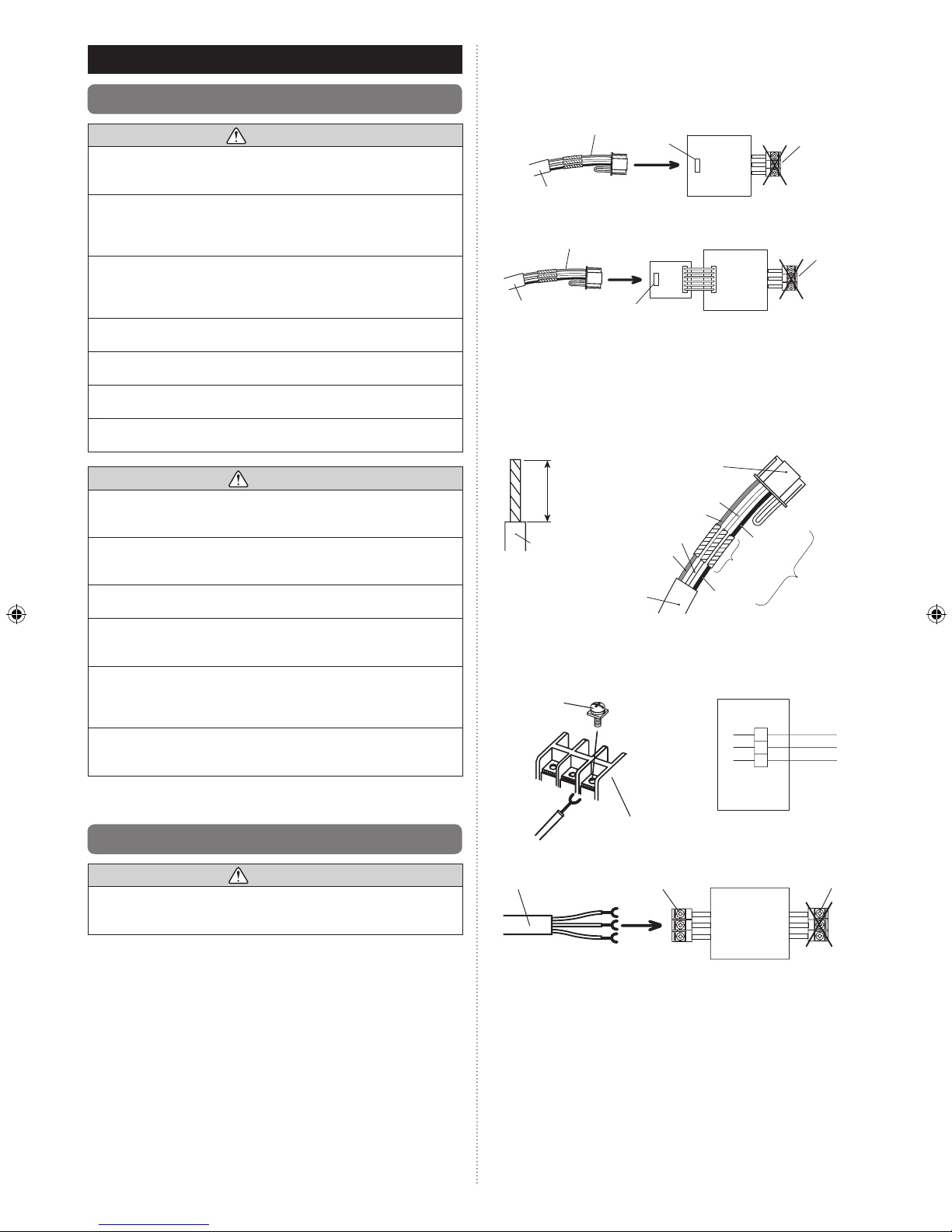
5.2. Connection of remote controller cable
CAUTION
When connecting the remote controller cable to the wall mounted type
and the oor type indoor unit, do not connect it to the outdoor unit or the
indoor unit power terminal block. It may cause a failure.
There are 2 methods to connect the remote controller cable to the indoor
unit. One is the connection using contained connecting cable and the other
is the connection the remote controller cable is connected to the exclusive
terminal block of the indoor unit.
Exclusive terminal block for remote controller connection method is different
depending on each model. Modify the remote controller cable as per below
description and connect it.
(For the details, refer to the installation manual of the indoor unit to be used.)
5.2.1 When connecting to the wall mounted type
and the oor type connector
Connect the remote controller cable to the connecting cable and insert it to
the connector.
Pattern 1
Connecting cable
Connecting cable
Remote controller
cable
Remote controller
cable
Connector
Connector
Communication
kit (option)
Indoor unit
Indoor unit
PCB
PCB
Outdoor
unit /
power
supply
terminal
block
Outdoor
unit /
power
supply
terminal
block
Pattern 2
Modify the cable as per below methods.
Use a tool to cut off the terminal on the end of the remote controller cable (1)
and then remove the insulation from the cut end of the cable as shown
in Fig. 1.
Connect the remote controller cable and connecting cable as shown in (2)
Fig. 2.
Be sure to insulate the connection between the cables.(3)
Fig. 1
Wire
Connecting
cable
Connector
White
White
Red
Red
Black
Black
Insulated
connection
Remote
controller cable
25/32 in.
(20 mm)
Fig. 2
5.2.2 When connecting to the exclusive terminal
block
Connect the end of remote controller cable directly to the exclusive terminal
block.
M4 screw
Terminal block
Black
3
2
1
White
Red
Indoor unit
side
Remote controller
cable
Remote controller
terminal block
Outdoor unit /
power supply
terminal block
Indoor unit
PCB
It may be failed if it is connected to the outdoor unit or the terminal block for
power supply.
Page 5

En-4
5.3. Installation
WARNING
When installing this unit, make sure that there are no children nearby.
Otherwise, injury or electric shock could result.
CAUTION
Before opening the case of this unit, completely discharge static electricity
charged on your body. Not doing so will cause trouble.
Do not touch the circuit board and circuit board parts directly with your
hands. Otherwise, injury or electric shock could result.
Be careful so that the front case does not fall after the front case are
removed. Otherwise, a damage of the front case could result.
To avoid incoming water or insects along the cable, always establish a
trap and seal the wiring hole.
Overtighten of the screws may cause a distortion or a damage of the rear
case.
Do not make any additional hole on the rear case to avoid a damage.
Do not use any other screws than the included ones. Using of other
screws may cause a product malfunction or damage.
5.3.1 Installation space
This product cannot be installed in wall.•
Recommendation installation height of the remote controller is 4.6ft. (1.4 m) •
(from the oor surface to the bottom of the remote controller).
Even when you install a remote controller to one of a switch box and the •
surface of a wall, secure the space shown in following gure. If spaces run
short, it will become difcult to remove a remote controller.
1-6/32 (30)
or more
8-21/32 (220)
or more*
Unit: in. (mm)
1-6/32 (30)
or more
1-6/32 (30)
or more
* Please secure enough space where a at screwdriver to take off a case
can be inserted.
5.3.2 Processing of the remote controller cable
Unit: in. (mm)
2-5/32 (55)
1. 12 V (Red)
2. Signal (White)
3. COM (Black)
1-25/32 (45)
1-6/32 (30)
10/32 (8)
10/32
(8)
10/32
(8)
5.3.3 Remove the front case
Insert the at screwdriver and remove the front case and rear case (1)
by twisting it slightly.
Hooks (2 places)
Flat screwdriver
Rear case
Front case
5.3.4 Installing the remote controller
A. When attaching to switch box:
Seal the wiring hole of the remote controller cable.(1)
Put a remote controller cable through the hole of the rear case.(2)
Fix the rear case by securing it with attached screws (2 places).(3)
Rear case
Trap
Box
Remote controller cable
Seal the wiring hole of the remote controller
cable with putty.
Putty
Trap
Screws
B. When attaching to the wall directly:
Seal the wiring hole of the remote controller cable.(1)
Put a remote controller cable through the back hole of the rear (2)
case of the main body.
Fix the rear case by securing it with attached screws (2 places).(3)
Rear case
Trap
Wall
Screws
Putty
Trap
Seal the wiring hole of the remote controller
cable with putty.
C. When routing the cable on-wall:
Cut off the cable guide of the front case with using a knife or a (1)
nipper.
Deburr the edge of the cable guide.(2)
Front case
Cut off
Fix the rear case by securing it with attached screws (2 places).(3)
Rear case
Screws
Epoxy putty
Remote controller cable
Page 6

En-5
5.3.5 Connect the cable to the terminals
Tightening torque
Terminal screw 7.1 to 10.6 lbf•in (0.8 to 1.2N • m)
1. 12V (Red)
2. Signal (White)
3. COM (Black)
Cable tie
3/32 in.
(2 mm)
GOOD
PROHIBITED
Remote controller
cable
Hole for cable tie
To avoid an excessive tension or pressure to the terminal block,
x the remote controller cable with the cable tie properly.
CAUTION
Be careful to avoid breaking the cable by over-tightening the cable tie.
When connecting the remote controller cables, do not over-tighten the
screws.
5.3.6 Setting the DIP switch
CAUTION
Do not set the DIP switch of this unit except as specied in this installation
manual or the operating manual supplied with the air conditioner. Please
set DIP switch according to designation.
Use an insulated screwdriver to set the DIP switches.
Set DIP switch No. 1 to ON to enable the memory backup of the settings
information.
Memory backup setting•
If the DIP switch No. 1 is not set to ON, the settings information will be lost
if there is a power failure.
* Registered information, such as that for the internal unit, is not erased
even if the DIP switch is turned off.
DIP switch
ON
OFF
1 2
Front case (back side)
No.
Switch state
Detail
OFF ON
DIP
switch
1
Invalidity
Validity
Memory backup setting
* Set to ON to use batteries for
the memory backup.
If batteries are not used, the
settings information stored in
memory will be deleted if there
is a power failure.
2
Dual remote controller setting
* Refer to “6.2. Dual remote
controllers”.
(
Factory setting)
5.3.7 Attach the front case
Insert after adjusting upper part of front case.•
When insert the front case, do not pinch the cable.•
Front case
Click!
PROHIBITED
GOOD
CAUTION
Insert the front case rmly. If improperly attached, it will cause the front
case to fall off.
When routing the cable on top of the front case:
Seal the cable guide of the front case of the remote controller cable with
an epoxy putty.
Thickness of sheath of the remote controller cable should be thicker •
than 1/32 in. (1 mm) or more. Or insulate it with a cable cover thicker
than 1/32 in. (1 mm) or more.
Cable cover
Epoxy putty
Page 7

En-6
6. INSTALLATION METHODS
6.1. Group control
A number of indoor units can be operated at the same time using a single •
remote controller.
Depending on the model, some indoor units cannot be connected for •
group control. (Group control is available for the duct type, the cassette
type, and the ceiling type indoor unit.)
Some functions may become unusable, depending on the combination of •
the indoor units that are connected in a group.
(1) Wiring method (indoor unit to remote controller)
EXAMPLE: Single Type
Indoor unit 0
Remote controller
Remote controller
cable
11223
3
Indoor unit 1 Indoor unit 2 Indoor unit 3
1 1 12 2 23 3 3
(2) Indoor unit address setting
Set each indoor unit address using the DIP switch of each indoor unit.
(Refer to the installation manual for the indoor unit.)
6.2. Dual remote controllers
Field setting can be performed only on the primary unit.•
Assignment of primary unit and secondary unit is necessary. No assign-•
ment will cause an error.
Depending on the model, some indoor units cannot be connected for dual •
remote controllers. (Dual remote controllers are available for the duct type,
the cassette type and the ceiling type indoor unit.)
Two separate remote controllers can be used to operate the indoor units.•
The timer and functions cannot be used on the secondary units. (For the •
details, refer to the operating manual.)
(1) Wiring method (indoor unit to remote controller)
Indoor unit
Remote controller
Primary unit
Secondary unit
Remote controller cable
1
1122233
3
(2) Remote controller DIP switch 1 setting
Set the remote controller DIP switch No. 2 according to the following
table.
Number of remote
controllers
Primary unit Secondary unit
DIP Switch No. 2 DIP Switch No. 2
1 (Normal) OFF –
2 (Dual) OFF ON
7. TURNING ON THE POWER
CAUTION
Recheck the wiring. Incorrect wiring will cause trouble.
Check the remote controller wiring and DIP switch settings.(1)
Install the front case. (2)
(in 5. INSTALLING THE REMOTE CONTROLLER).
Check the indoor and outdoor unit wiring and circuit board switch set-(3)
tings, and then turn on the indoor and outdoor units. After message
“Please wait” is displayed on the remote controller display, “Language”
screen is displayed.
Please wait
OK:
Language
Italiano
Español
English
Ελληνικά
Português
Русский
Deutsch
Français
Türkçe
8. INITIAL SETTING
When “Language” screen is displayed, perform the initial setting as in the
following procedure:
1
Select a language with the [Cursor button] on the “Language” screen
displayed when the start-up is completed.
OK:
Language
Italiano
Español
English
Ελληνικά
Português
Русский
Deutsch
Français
Türkçe
When conrmed by pressing the [Enter button], the “Temp. unit” screen
is displayed.
2
Switch the unit for temperature “°C” or “°F” with [Cursor button (Up/
Down)].
When [Cancel button] is pressed, it returns to the “Language” screen.
OK:
Cancel:
Temp. unit
Temp. unit
°
F
(Temp. unit : Temperature unit)
When [Enter button] is pressed, the “Change display format” screen is
displayed.
3
Set the display format of “Date format” and “Time format”.
Switch the setting item with [Cursor button (Left/Right)] and conrm
with the [Cursor button (Up/Down)].
When [Cancel button] is pressed, it returns to the “Temp. unit” screen.
Cancel:
Date format
Change display format
Day/Month/Year
0:00-11:59AM/PM
Time format
OK:
-Note-
Following display formats are available for setting.
Date format : Time format:
• Day/Month/Year • 0:00-23:59
• Month/Day/Year • 0:00-11:59 AM/PM
• Year/Month/Day • 12:00-11:59 AM/PM
When [Enter button] is pressed, the “Date” screen is displayed.
Page 8

En-7
4
Set the “Day”, “Month”, and “Year”.
Switch the setting item with [Cursor button (Left/Right)], and adjust
with [Cursor button (Up/Down)].
When [Cancel button] is pressed, it returns to the “Change display
format” screen.
Year
Day
Monday
08 2012
Month
Date
20
OK:
Cancel:
When [Enter button] is pressed, the “Time” screen is displayed.
5
Set the “hour” and “min”.
Switch the setting item by [Cursor button (Left/Right)], and adjust with
[Cursor button (Up/Down)].
“Min” can be set quickly if the button is pressed continuously.
When [Cancel button] is pressed, it returns to the “Date” screen.
min
00
AM
hour
Time
OK:
Cancel:
10:
When [Enter button] is pressed, the “Conrmation” screen is displayed.
6
When setting is completed, select “Yes” with [Cursor button (Left/
Right)], and press [Enter button].
When correcting a setting, set it again as it returns to the “Language”
screen when “No” is selected and press [Enter button].
Initial setting will be ended. OK?
No
Yes
9. SERVICE SCREEN SETTING
When [Menu button] is pressed twice while “Monitor” screen is displayed, it
switches to the “Submenu” screen.
Press the [Screen switch button (Left)] and [Screen switch button (Right)]
simultaneously for 5 seconds to switch to “Service” screen.
Back:
Setting:
Date and time
Submenu
[
1/2
]
Monitor
Screen
Filter sign
R.C. sensor control
Room temp. display
Off
Off
Mo
10:00AM
Back:
Setting:
Service
Mo 10:00AM
Function setting
Error history
I.U.address verification
Version
Test run
(R.C. Sensor control : Remote Controller sensor control)
(I.U.address verication : Indoor Unit address verication)
Service screen
Function name
Setting
Primary unit Secondary unit
Test run
Function setting
Error history
I.U.address verication
Version
9.1. Test run
If the unit is operating, turn it off.•
Test run stops in 60 minutes.• When the [On/Off button] is pressed during
the test run, the test run will be canceled.
After completing the test run, wait enough until starting the operation.•
1
When [Menu button] is pressed twice while “Monitor” screen is displayed, it switches to the “Submenu” screen.
If [Menu button] is pressed while the “Submenu” screen is displayed,
the display returns to the “Monitor” screen.
Back:
Setting:
Date and time
Submenu
[
1/2
]
Monitor
Screen
Filter sign
R.C. sensor control
Room temp. display
Off
Off
Mo
10:00AM
2
Press the [Screen switch button (Left)] and [Screen switch button
(Right)] simultaneously for 5 seconds to switch to “Service” screen.
Back:
Setting:
Service
Mo 10:00AM
Function setting
Error history
I.U.address verification
Version
Test run
When you select [Test run] with the [Cursor button (Up/Down)] and press the
[Enter button], following conrmation screen is displayed.
To start the test run, select “Yes” with the [Cursor button (Left/Right)], and
press the [Enter button].
In Set temp, test run is displayed.
The test run will be performed. OK?
No
Yes
►
Mod e
Menu
Cool
Monitor
Set tem p.
Fan
High
Mo
10:00AM
Test
run
9.2. Function setting
This procedure changes the function settings used to control the indoor unit
according to the installation conditions. Incorrect settings can cause the
indoor unit to malfunction. This procedure should be performed by authorized installation or service personnel only.
Perform the “FUNCTION SETTING” according to the installation conditions
using the remote controller. (Refer to the indoor unit installation manual for
details on the function numbers and setting values.)
Perform the setting during the operation is stopped.
1
When [Menu button] is pressed twice while “Monitor” screen is displayed, it switches to the “Submenu” screen.
If [Menu button] is pressed while the “Submenu” screen is displayed,
the display returns to the “Monitor” screen.
Back:
Setting:
Date and time
Submenu
[
1/2
]
Monitor
Screen
Filter sign
R.C. sensor control
Room temp. display
Off
Off
Mo
10:00AM
2
Press the [Screen switch button (Left)] and [Screen switch button
(Right)] simultaneously for 5 seconds to switch to “Service” screen.
Back:
Setting:
Service
Mo 10:00AM
Function setting
Error history
I.U.address verification
Version
Test run
Page 9

En-8
3
Select [Function setting] with pressing the [Cursor button (Up/Down)],
and press the [Enter button].
Back:
Setting:
Service
Mo 10:00AM
Function setting
Error history
I.U.address verification
Version
Test run
4
Select [R.C. address] of the target indoor unit with pressing the [Cursor button (Up/Down)].
(R.C. Address : Remote Controller Address)
C
ancel
:
OK:
Function setting
Mo 10:00AM
R.C. Function Setting
address No. No.
00
00
00
Version Error history
5
Select the [Function No.] with pressing the [Cursor button (Left/
Right)], and select the Function No. to be set with pressing the [Cursor button (Up/Down)].
C
ancel
:
OK:
Function setting
Mo 10:00AM
R.C. Function Setting
address No. No.
Version Error history
00 00 00
6
Select the [Setting No.] with pressing the [Cursor button (Left/Right)],
and select the Setting No. to be set with pressing the [Cursor button
(Up/Down)],and press the [Enter button].
C
ancel
:
OK:
Function setting
Mo
10:00AM
R.C. Function Setting
address No. No.
Version Error history
00 00 00
-Note-
“Service” screen or “Function setting” screen return to the “Submenu”
screen if there is no button operation for 1 minute.
9.3. Error history
The error history can be displayed.
Select [Error history] with the [Cursor button (Up/Down)], and press the
[Enter button].
Back
Setting:
Service
Mo 10:00AM
Function setting
Error history
I.U.address verification
Version
Test run
Error history
[
1/4 ]
Mo 10:00AM
No.
Date Time
Address
Code
1 30/07/2012 9:00AM 00 Er 411
2 28/07/2012 8:00AM 00 Er J2u
3 13/07/2012 11:00AM 00 Er 156
4 08/07/2012 1:00PM 01 Er 141
Back:
Function set... I.U. address ...
9.4. I.U. address verication
The refrigerant address and the indoor unit address can be displayed.
Select [I.U. address verication] with the [Cursor button (Up/Down)], and
press the [Enter button].
Back
Setting:
Service
Mo 10:00AM
Function setting
Error history
I.U.address verification
Version
Test run
Back : OK :
I.U. address verification
Mo 10:00AM
R.C. Refrigerant Indoor Unit
address address address
00
00
00
Error history Version
9.5. Version
Software version of the remote controller can be displayed.
Select [Version] with the [Cursor button (Up/Down)], and press the [Enter
button].
Back
Setting:
Service
Mo 10:00AM
Function setting
Error history
I.U.address verification
Version
Test run
Version
Mo 10:00AM
E031VXXPXXL
XX
Back:
I.U. address ... Function set...
10. SETTING THE ROOM TEMPERATURE
DETECTION LOCATION
The detection location of the room temperature can be selected from the
following 2 examples. Choose the detection location that is best for the
installation location.
Refer to “9.2. Function setting”.
A. Indoor unit setting (factory setting)
The room temperature is detected by the indoor unit temperature sensor.
When use this function, set “Indoor room temperature sensor switching
function (Function Number:42)” of “9.2. Function setting” to “No(00)”.
Indoor unit
A
B. Indoor unit/remote controller setting (room temperature sensor
selection)
The temperature sensor of the indoor unit or the remote controller can be
used to detect the room temperature.
When use this function, set “Indoor room temperature sensor switching
function (Function Number:42)” of “9.2. Function setting” to “Yes(01)”.
Enable the room temperature sensor selection in function setting, which (1)
will be described later.
Select either of the temperature sensor on the indoor unit or on the (2)
remote controller for temperature detection. (For how to congure the
setting, refer to “5-5. R.C. sensor control” in the operating manual.)
B
Indoor unit
CAUTION
When select the “Remote controller setting”, if the detected temperature
value between the temperature sensor of the indoor unit and the tempera-
ture sensor of the remote controller varies signicantly, it is likely to return
to the control status of temperature sensor of the indoor unit temporarily.
As the temperature sensor of remote controller detects the tempera-
ture near the wall, when there is a certain difference between the room
temperature and the wall temperature, the sensor will not detect the room
temperature correctly sometimes. Especially when the outer side of the
wall on which the sensor is positioned is exposed to the open air, it is
recommended to use the temperature sensor of the indoor unit to detect
the room temperature when the indoor and outdoor temperature differ-
ence is signicant.
The temperature sensor of the remote controller is not only used when
there is a problem in the detection of the temperature sensor of the indoor
unit.
Page 10

En-9
1 ) Indoor room temperature sensor switching function
(Only for Wired remote controller)
The following settings are needed when use the control by Wired remote
controller temperature sensor.
(
...Factory setting)
Setting Description Function No. Setting No.
No
42
00
Yes 01
* If setting No. is “00” :
Room temperature is controlled by the indoor unit temperature sensor.
* If setting No. is “01” :
Room temperature is controlled by either indoor unit temperature sensor
or remote controller unit sensor.
2 )
Setting record
Record the setting change in the following table.
Setting Description Setting No.
Room temperature sensor
switching
After completing the FUNCTION SETTING, be sure to turn off the power
and turn it on again.
11. MANAGEMENT FUNCTION
Restricts the operations of following power-saving functions by non-author-
ized person, and helps more energy-efcient operation of the system.
With the password control, only the administrator can get access to the
function setting.
For the controlled functions, perform the setting change in “Management
function” screen.
Settings Items:
Function
Economy•
Set temp. auto return•
Set temp. range•
Timer
On timer•
Off timer•
Weekly timer•
Auto-off timer•
(Set temp. auto return : Set temperature auto return)
(Set temp. range : Set temperature range)
For the details on each function, refer to “2-2. Setting items in Menu” in the
operating manual.
11.1. Password setting
Preset value of password is “0000”
Change the password as necessary so that the setting change cannot be
done by other than the administrator.
The changed password should be managed properly by the administrator.
A password (4-digit) required when setting up a Management function can
be changed.
1
When [Menu button] is pressed twice while “Monitor” screen is displayed, it switches to the “Submenu” screen.
If [Menu button] is pressed while the “Submenu” screen is displayed,
the display returns to the “Monitor” screen.
Back:
Setting:
Date and time
Submenu
[
1/2
]
Monitor
Screen
Filter sign
R.C. sensor control
Room temp. display
Off
Off
Mo
10:00AM
2
When [Initial] is selected in [Submenu] screen, “Initial” screen is
displayed. Enter current password with the [Cursor button], and press
the [Enter button].
Initial
Management
Key lock select Child lock
Submenu
[
2/2
]
Mo 10:00A M
Back:
Setting:
Monitor
3
Select [Password setting (Management)] in the “Initial” screen, and
press the [Enter button].
Mo
10:00AM
Back:
Setting:
Initial
Language
English
Temp. unit
Password setting (Management)
°F
Filter sign
Management
4
Enter current password.
With pressing the [Cursor button (Up/Down)], enter the number. When
you press the [Cursor button (Right)], the cursor moves to next digit.
After you enter the 4 digits, press the [Enter button].
0 0 00
Mo
10:00AM
Cancel :
OK:
Enter current password.
Password setting
-Note-
When you forget a password, please push a [Menu button] and the
[Cancel button] at the same time for 3 seconds. Screen switches to
"Enter new password" screen.
5
Enter new password with same procedure in step 4.
0 0 00
Mo
10:00AM
Cancel :
OK:
Enter new password.
Password setting
Mo
10:00AM
Back:
Setting:
Initial
Language
English
Temp. unit
Password setting (Management)
°F
Filter sign
Management
11.2. Management setting
Management setting is a function that restricts the operation of some functions on this remote controller.
The functions to be restricted are set in this setting, but not in each functional
setting.
Example: To restrict Economy setting to [ON]
Set to [ON] on all the other signal source except this remote controller.
1
When [Menu button] is pressed twice while “Monitor” screen is displayed, it switches to the “Submenu” screen.
If [Menu button] is pressed while the “Submenu” screen is displayed,
the display returns to the “Monitor” screen.
Back:
Setting:
Date and time
Submenu
[
1/2
]
Monitor
Screen
Filter sign
R.C. sensor control
Room temp. display
Off
Off
Mo
10:00AM
2
When [Management] is selected in [Submenu] screen, “Management”
screen is displayed. Enter current password with the [Cursor button],
and press the [Enter button].
Initial
Management
Key lock select Child lock
Submenu
[
2/2
]
Mo 10:00A M
Back:
Setting:
Monitor
0 0 00
Mo
10:00AM
Cancel :
OK:
Initial
Enter current password.
Management
Date and time
-Note-
If the entered password is not correct, message “Password is not
correct” is displayed. Enter correct password.
Page 11

En-10
3
When correct password is entered, “Management function” screen is
displayed.
To select the function to be controlled by [Management], select [Edit]
with pressing the [Cursor button (Up/Down)], and press the [Enter
button].
“Management select” screen is displayed.
Mo
10:00AM
Back:
Setting:
Edit
Management function
Mo
10:00AM
Back:
Setting:
Management select
[
1/2
]
Economy
Set temp.auto return
Set temp.range
On timer
Off timer
4
Select the target function with the [Cursor button (Up/Down)] and
press the [Enter button]. Then the setting eld for the restriction setting is displayed.
Mo
10:00AM
Back:
Setting:
Management select
[
1/2
]
Economy
Set temp.auto return
Set temp.range
On timer
Off timer
Mo
10:00AM
Cancel:
OK:
Management select
[
1/2
]
Economy
Set temp.auto return
Set temp.range
On timer
Off timer
Select the setting with the [Cursor button (Up/Down)], and press the [Enter
button].
Mo
10:00AM
Cancel:
OK:
Management select
[
1/2
]
Economy
Set temp.auto return
Set temp.range
On timer
Off timer
Mo
10:00AM
Back:
Setting:
Management select
[
1/2
]
Economy
Set temp.auto return
Set temp.range
On timer
Off timer
If there is another setting to be changed, you can continue the conguration.
Mo
10:00AM
Back:
Setting:
Management select
[
1/2
]
Economy
Set temp.auto return
Set temp.range
On timer
Off timer
To complete the setting, press the [Cancel button].
Functions marked check in “Management select” screen are listed in “Management function” screen.
Mo
10:00AM
Back:
Setting:
Edit
Management function
Economy
Disable
Disable
Off
Set temp. range
On timer
5
In “Management function” screen, you can change the detailed setting
on each function.
For how change the setting, refer to each function setting in
“3. FUNCTION SETTING” in the operating manual.
Mo
10:00AM
Back:
Setting:
Edit
Management function
Economy
Disable
Disable
Off
Set temp. range
On timer
-Note-
If the function you are selecting is restricted by [Management]
function, following message is displayed in the operation guidance
display. The message is displayed constantly during the management
function is enabled.
XXX XXX
XXX XXX
Restrict ed by the manag ement function
Back :
12. OTHERS
12.1. Error code
If an error occurs, the power indicator (green) blinks and the following
display will be shown.
If “Error” is displayed, immediately stop the air conditioner operation, and
consult authorized service personnel.
When there is an error on this remote controller:•
Code : XXXXXX
Remote controller
Error
Mo
10:00AM
Error code
Error code Contents
Er 12.1
EE 1c
Wired remote controller communication error•
Er 15.4
EE 1d
Incompatible indoor unit is connected•
Indoor unit date acquisition error•
Primary unit / Secondary unit setting error•
Er CC.1
EE CC.1
Remote controller sensor error•
When there is an error on the indoor unit:•
Code : Er 4 1. 1
R.C. address : 00
Error
Mo
10:00
Moni tor
Code : XXXXXX
R.C. address : 00
Error
Mo
10:00AM
Moni tor
Error code
Address number of the
relevant indoor unit
 Loading...