

Page 1
EnglishDeutschFrançaisEspañolItalianoEλληvIkάPortuguêsРусскийTϋrkçe
AIR CONDITIONER
CENTRAL REMOTE
CONTROLLER
UTY-DMMYM
UTY-DMMGM
UTY-DMMXM
PART NO. 9380222019-02
INSTALLATION MANUAL
For authorized service personnel only.
MANUEL D'INSTALLATION
Pour le personnel agréé uniquement.
MANUALE DI INSTALLAZIONE
Esclusivamente destinato al personale autorizzato.
РУКОВОДСТВО ПО УСТАНОВКЕ
Только для авторизованного обслуживающего персонала.
INSTALLATIONSANLEITUNG
Nur für autorisiertes Fachpersonal.
MANUAL DE INSTALACIÓN
Sólo para personal de mantenimiento autorizado.
MANUAL DE INSTALAÇÃO
Apenas para técnicos de assistência autorizados.
ΕΓΧΕΙΡΙΔΙΟ ΕΓΚΑΤΑΣΤΑΣΗΣ
Μόνο για εξουσιοδοτημένο προσωπικό του σέρβις.
MONTAJ KILAVUZU
Sadece yetkili servis personeli içindir.
Page 2
En-1
INSTALLATION MANUAL
PART NO. 9380222019-02
CENTRAL REMOTE CONTROLLER
Contents
1. SAFETY PRECAUTIONS ....................................................................... 1
2. ACCESSORIES ...................................................................................... 1
3. ELECTRICAL REQUIREMENT .............................................................. 1
4.
SELECTING AN INSTALLATION LOCATION
4.1. Dimensions ...................................................................................... 1
4.2. Name of parts .................................................................................. 2
5.
INSTALLING THE REMOTE CONTROLLER
5.1. Flow of installation ........................................................................... 2
5.2. Wiring ............................................................................................... 2
5.3. Installation ........................................................................................ 3
5.4. Setting the DIP switch ...................................................................... 4
6. TURNING ON THE POWER .................................................................... 4
1. SAFETY PRECAUTIONS
The “SAFETY PRECAUTIONS” indicated in the manual contain important •
information pertaining to your safety. Be sure to observe them.
For details of the operation methods, refer to the operating manual.•
Request the user to keep the manual on hand for future use, such as for •
relocating or repairing the unit.
WARNING
This mark indicates procedures which, if improperly
performed, might lead to the death or serious injury
of the user.
• Perform electr ic al work by an authori ze d se rv ic e pe rsonnel in
acc ordance with the installation manual and the electrical wiring
regulations or implementation regulations of the country. Improper
electric work will cause electric shock or a re.
• Perform installation work in accordance with the installation manual.
Request an authorized service personnel to perform installation work.
Do not install this unit by yourself. Improper installation will cause injury,
electric shock, re, etc.
• In the event of a malfunction (burning smell, etc.), immediately stop
operation, turn off the electrical breaker, and consult authorized service
personnel.
Do not install the unit in the following areas:
• Do not install the unit near a source of heat, steam, or ammable gas.
• Area lled with mineral oil or containing a large amount of splashed oil
or steam, such as a kitchen. It will deteriorate plastic parts, causing the
parts to fall or the unit to leak water.
• Area that generates substances that adversely affect the equipment,
such as sulfuric gas, chlorine gas, acid, or alkali. It will cause the
copper pipes and brazed joints to corrode, which can cause refrigerant
leakage.
• Area containing equipment that generates electromagnetic interference.
It will cause the control system to malfunction, preventing the unit from
operating normally.
• Area that can cause combustible gas to leak, contains suspended
carbon bers or ammable dust, or volatile inammables such as paint
thinner or gasoline. If gas leaks and settles around the unit, it can
cause a re.
• Do not use the unit for special purposes, such as storing food, raising
animals, growing plants, or preserving precision devices or art objects.
It can degrade the quality of the preserved or stored objects.
• Install the unit in a well-ventilated place avoiding rains and direct
sunlight.
• Do not operate this unit when your hands are wet.
Touching the unit with wet hands will cause an electric shock.
• If children may approach the unit, take preventive measures so that
they cannot reach the unit.
CAUTION
This mark indicates procedures which, if improperly
performed, might possibly result in personal harm
to the user or damage to property.
• Pay abundant care when transporting this unit because it is a precision
device. Improper transportation will cause trouble.
• Do not touch the switches with sharp objects. Doing so will cause
injury, trouble, or electric shock.
• Do not expose this unit directly to water. Doing so will cause trouble,
electric shock, or heating.
• Do not set vessels containing a liquid on this unit. Doing so will cause
heating, re, or electric shock.
• Dispose of the packing materials safely. Tear and dispose of the plastic
packing bags so that children cannot play with them. There is the
danger of suffocation if children play with the original plastic bags.
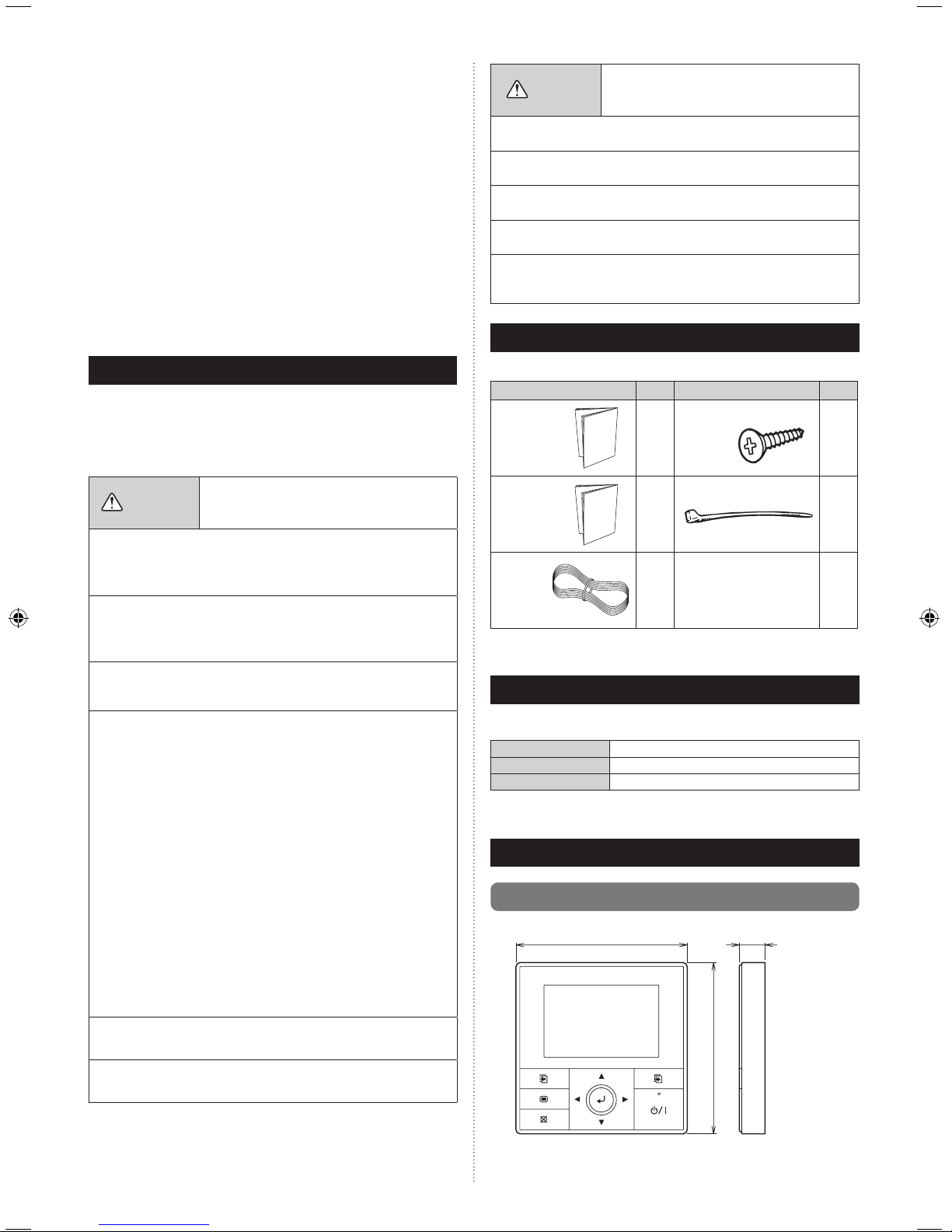
2. ACCESSORIES
The following installation parts are supplied. Use them as required.
Name and Shape Q’ty Name and Shape Q’ty
Installation
manual
(This manual)
1
Screw (M4 × 16 mm)
2
Operating
manual
1
Binder
1
Remote
Controller
Cable
1
Use of this product requires a remote controller cable. These are provided
as service parts, so please contact authorized service personnel.
3. ELECTRICAL REQUIREMENT
When connecting the Central remote controller and the Branch box, use the
following wiring.
Cable
Remote controller cable
Size
0.33 mm2 (22AWG)
Remarks
Sheathed PVC cable, Polar 3 core
1
We recommend that you purchase our service parts for the remote controller
cable. Contact service personnel to purchase this.
4.
SELECTING AN INSTALLATION LOCATION
4.1. Dimensions
120 21.3
Unit: mm
120
Page 3

En-2
Unit: mm
30 33.5
23
9
4.5
12.5
63.5
83.5
4.5
45.3
15.3
4.5
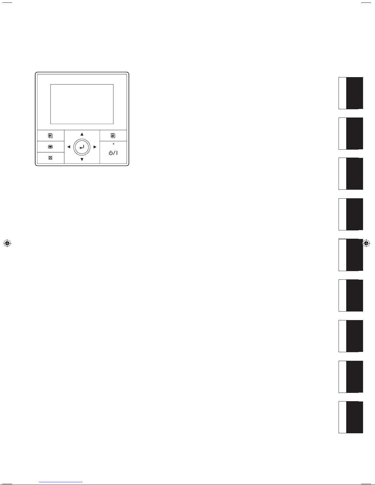
4.2. Name of parts
(1)
(2)
(6)
(3)
(7)
(4) (8)
(9)
(5)
(1) Display panel (with backlight) (6) Screen switch button (Right)
(2) Screen switch button (Left) (7) Power indicator
(3) Menu button (8) On/Off button
(4) Cancel button (9) Enter button
(5) Cursor button
5.
INSTALLING THE REMOTE CONTROLLER
5.1. Flow of installation
The following is the ow of the installation of Central remote controller.
••••••••
••••••••
••••••••
Refer to [5.2. Wiring]
Refer to [5.3. Installation]
Refer to
[5.4. Setting the DIP switch]
Refer to Operating manual
Wiring
Installation
Turning on
the power
Setting
the DIP switch
Setting
• Language setting
• Temp. unit setting
• Date setting
• Time setting
• Change display format setting
• SETTING
• INSTALLATION
5.2. Wiring
WARNING
• Before starting installation work, turn off the power of the connection
desti nation. Do not turn on the power ag ain until in stall ation is
completed. Otherwise, it will cause electric shock or re.
• Use the accessories or specied connection cables.
Do not modify connection cables other than those specied, do not
use extension cords, and do not use independent branch wiring. The
allowable current will be exceeded and cause electric shock or re.
• Install the connection cables securely to the terminal block. Conrm
that external force is not applied to the wire. Use connection cables
made of the specified wire. If intermediate connection or insertion
xing are imperfect, it will cause electric shock, re, etc.
• When connecting the power cable and transmission cable, layout the
wiring so that the cover of this unit is securely xed. If the cover is
imperfectly xed, it may cause re or overheating of the terminals.
• Do not connect the ground wire to a telephone ground wire, water
pipe, or conductor rod.
• Always fasten the outside covering of the connection cord with the
cord clamp. (If the insulator is chafed, electric leakage may occur.)
•
When performing cable wiring work, be sure that it does not touch the
user. Doing so will cause injury or electric shock.
• If any cable is damaged, do not repair or modify it yourself. Improper
work will cause electric shock or re.
CAUTION
• Do not parallel to the remote controller cables, indoor and outdoor
connection cable, and power supply cables of Branch box. It may
cause erroneous operation.
• When performing wiring work, be careful not to damage the cable
or injure yourself. Also, connect the connectors securely. Loose
connectors will cause trouble, heating, re, or electric shock.
• Install the remote control cable 1 m away from television and radio to
avoid distorted images and noise.
• Per form wi ring so that wat er does n ot enter this unit along th e
external wiring. Always insta ll a trap to the wiri ng or take other
countermeasures. Otherwise it will cause trouble or electric shock or
re.
• Conrm the name of each unit and name of each terminal block of the
unit and connect the wiring in accordance with the directions given
in the manual so that there is no incorrect wiring. Incorrect wiring will
damage the electric parts and cause smoke and re.
• When installing the connection cable near a source of electromagnetic
waves, use shielded cable. Otherwise, a breakdown or malfunction
could result.
Page 4

En-3
Example)
Wiring diagram when 3 units of branch boxes are connected
123
123 123123
Branch box
(Primary)
REMOTE
CONTROL
Branch box
(Secondary 1)
REMOTE
CONTROL
Branch box
(Secondary 2)
REMOTE
CONTROL
Central remote controller
Remote controller cable
• Total remote controller cable length:
MAX. 500 m
5.3. Installation
WARNING
• Always use the accessories and specified installation work parts.
Check the state of the installation parts. Not using the specied parts
will cause units to fall off, water leakage, electric shock, re, etc.
• When installing this unit, make sure that there are no children nearby.
Otherwise, injury or electric shock could result.
• After installing this unit, perform the test run to conrm that the unit
is operating properly. Then, explain the operation of this unit to the
customer.
CAUTION
• Do not set the DIP switch of this unit except as specified in this
installation manual or the installation manual supplied with the air
conditioner. Setting the switches other than specified will cause an
accident or trouble.
• Use an insulated screwdriver to set the DIP switches.
• Before opening the case of this unit, completely discharge static
electricity charged on your body. Not doing so will cause trouble.
• Do not touch the circuit board and circuit board parts directly with your
hands. Otherwise, injury or electric shock could result.
• Tightening the mounting screws too tight will damage the case of this
unit.
• Be careful so that the front cover does not fall after the front cover are
removed. Otherwise, injury could result.
(1) Remove the insulation of the remote controller cable.
8
8
8
30
45
55
Unit : mm
1. 12V (Red)
2. Signal (White)
3. COM (Black)
(2) Insert the at-blade screwdriver and remove the front case and rear
case by twisting it slightly.
Flat screwdriver
Front case
Hooks (2 places)
Rear case
(3) Install the rear case to the wall, box, etc. with 2 screws (M4 × 16 mm).
Fix the 2 screws in either horizontal or vertical position.
A. When mounting on the box:
• Attach the case after leading the cable.
Screws
Box
Remote controller cable
Rear case
B. When the cable is along the wall:
• Mount the rear case on the wall.
• Cut off a hole for cabling in the front case.
Front case
Cut off
CAUTION
•
When connecting the remote controller cable, take measures to prevent
the water or insects coming into the remote controller through the cable,
such as to provide the trap or close the hole for cabling with the putty.
Putty
Putty
Putty
Trap
Trap
Trap
(4) Setting up the DIP switch. Refer to [5.4. Setting the DIP switch].
(5) Connect the cable to the terminals on the front case. Fix the cable
together with the sheath with the binder. Cut off the excess binder.
Tightening torque
Terminal screw 0.8 to 1.2N • m (8 to 12 kgf • cm)
Page 5

En-4
5.4. Setting the DIP switch
CAUTION
• Install the remote controller cables so as not to be direct touched with
your hand.
• Do not touch the remote controller PC board and PC board parts
directly with your hands.
Set DIP switch No. 1 to ON to enable the memory backup of the settings
information.
• Memory backup setting
If the DIP switch No. 1 is not set to ON, the settings information will be
lost if there is a power failure.
* Registered information, such as that for the internal unit, is not erased
even if the DIP switch is turned off.
1 23456
DIP Switch
Front case (back side)
ON
OFF
No.
Switch state
Detail
OFF ON
DIP
switch
1
Invalidity Validity
Memory backup
setting
* Set to ON to use
batteries for the memory
backup.
If batteries are not used,
the settings information
stored in memory will
be deleted if there is a
power failure.
2
Cannot be used.
(Do not change)
3
Cannot be used.
(Do not change)
4
Cannot be used.
(Do not change)
5
Cannot be used.
(Do not change)
6
Cannot be used.
(Do not change)
(
Factory setting)
6. TURNING ON THE POWER
CAUTION
• Recheck the wiring. Incorrect wiring will cause trouble.
For setting and operating of the Central remote controller, refer to the
separate operating manual.
1. 12V (Red)
2. Signal (White)
3. COM (Black)
Binder
Hole for binder
Remote controller
cable (sheath)
2 mm
No good
Good
No good
CAUTION
• Be careful to avoid breaking the cable by over-tightening the binder.
• When connecting the remote controller cables, do not over-tighten the
screws.
(6) Attach the front case.
• Insert after adjusting upper part of front case.
• When insert the front case, do not pinch the cable.
Front case
Good
Click!
No good No good No good
CAUTION
• Insert the upper case rmly. If improperly attached, it will cause the
upper case to fall off.
 Loading...