

Page 1
CENTRAL REMOTE CONTROLLER
UTY-DMMUM
OPERATING MANUAL
English
KEEP THIS OPERATION MANUAL FOR FUTURE REFERENCE
P/N9380221005
Page 2

Contents
7. FUNCTION SETTING
1. INTRODUCTION
1-1. Safety precautions ...............................................2
1-2. Features and functions ........................................2
1-3. Name of parts .......................................................3
1-3-1. About the Display panel ......................................3
1-3-2. About the Screen switch button (Left/Right) ........3
1-3-3. About the Menu button ........................................4
1-3-4. About the Cancel button ......................................4
1-3-5. About the Cursor button ......................................4
1-3-6. About the Enter button ........................................4
1-3-7. About the Power indicator ...................................4
1-3-8. About the On/Off button ......................................4
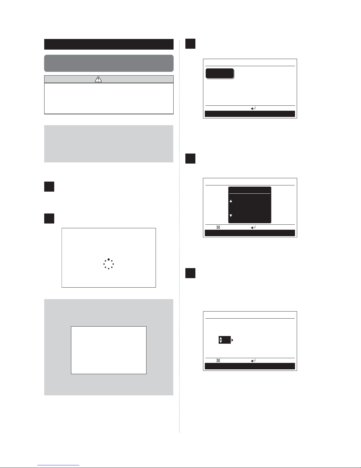
2. INITIALIZATION
2-1. Initial settings
(When starting for the rst time).........................5
3. PREPARATION
3-1. Turning on the power ...........................................7
3-2. Checking the time ................................................7
3-3. About the key lock ...............................................8
4. MONITOR SCREEN
4-1. About the Monitor screen ....................................8
4-1-1. Operation mode display ......................................8
4-1-2. Indoor units display .............................................9
4-1-3. Function display ..................................................9
4-1-4. Setting menu .......................................................9
5. ON/OFF BUTTON OPERATION
5-1. Operation with On/Off button ............................10
6. OPERATION SETTING
6-1. About the Operation setting ..............................10
6-2. Switching to the “Operation” screen ...............11
6-2-1. Operation/setting of all indoor units at once ...... 11
6-2-2. Operation/setting of each indoor unit ................ 11
6-3. Operation setting................................................12
6-3-1. On/Off operation ................................................12
6-3-2. Operation mode setting .....................................12
6-3-3. Room temperature setting.................................13
6-3-4. Fan speed setting..............................................13
6-3-5. Minimum heat setting ........................................13
6-3-6. Economy setting................................................14
7-1. About the Function setting................................14
7-2. Switching to the “Function” screen .................14
7-3. Function setting .................................................15
7-3-1. Minimum heat (All) setting.................................15
7-3-2. Economy (All) setting ........................................15
7-3-3. Outdoor unit low noise operation setting ...........16
7-3-4. Schedule select .................................................17
8. SCHEDULE SETTING
8-1. About the Schedule setting ...............................18
8-1-1. About the Schedule name .................................18
8-1-2. About the setting of the time and operations.....18
8-2. Switching to the “Schedule” screen ................18
8-2-1.
Setting of the same schedule for all indoor units
8-2-2. Setting of the schedule for each indoor unit ......18
8-3. Schedule setting ................................................19
8-3-1. Selection of schedule name ..............................19
8-3-2. Setting of Enable/Disable of schedule ..............19
8-3-3. Selection of the day of the week .......................20
8-3-4. Setting of the time and operations ....................20
9. SUBMENU SETTING
9-1. About the Submenu setting ..............................22
9-2. Switching to the “Submenu” screen ................22
9-3. Date/Time setting ...............................................23
9-3-1. Date setting .......................................................23
9-3-2. Time setting .......................................................23
9-3-3. Summer time (Daylight saving time) setting......24
9-3-4. Change display format setting...........................24
9-4. Screen setting ....................................................25
9-4-1. Automatic off time setting ..................................25
9-4-2. Brightness setting .............................................25
9-4-3. Contrast setting .................................................25
9-5. R.C. prohibition setting......................................26
9-6. Initial setting .......................................................27
9-6-1 Language setting...............................................27
9-6-2. Temperature unit setting....................................27
10. OTHERS
10-1. Troubleshooting ...............................................28
10-2. Error code .........................................................28
.....18
En-1
Page 3
1. INTRODUCTION
1
1-1. Safety precautions
The “SAFETY PRECAUTIONS” indicated in the manual con-•
tain important information pertaining to your safety. Be sure
to observe them.
For details of the operation methods, refer to the operating •
manual.
Request the user to keep the manual on hand for future use, •
such as for relocating or repairing the unit.
• Do not use re near this unit or place a heating apparatus
nearby. It may cause malfunction.
• Do not touch the switches with sharp objects. Doing so
will cause injury, trouble, or electric shock.
• Do not insert articles into the slit parts of this unit. Doing
so will cause trouble, heating, or electric shock.
1
1-2. Features and functions
This mark indicates procedures
WARNING
which, if improperly performed,
might lead to the death or serious
injury of the user.
• In the event of a malfunction (burning smell, etc.),
immediately stop operation, turn off the electrical
breaker, and consult authorized service personnel.
• Do not repair or modify any damaged cable by your self.
Let the authorized service personnel to do it. Improper
work will cause an electric shock or a re.
• This unit contains no user-serviceable parts. Always
consult authorized service personnel for repairs.
• When moving, consult authorized service personnel for
disconnection and installation of this unit.
• Do not touch with wet hands. It may cause an electric
shock.
• If children may approach the unit, take preventive
measures so that they cannot reach the unit.
• Do not repair or modify by yourself. It may cause a fault
or accident.
• Do not use ammable gases near the unit. It may cause
a re from leaking gas.
This mark indicates procedures which,
CAUTION
if improperly performed, might possibly
result in personal harm to the user or
damage to property.
• Do not set vessels containing a liquid on this unit. Doing
so will cause heating, re or electric shock.
• Do not expose this unit directly to water. Doing so will
cause trouble, electric shock or heating.
• Dispose of the packing materials safely. Tear and dispose
of the plastic packing bags so that children cannot play
with them. There is the danger of suffocation if children
play with the original plastic bags.
• Do not place electrical devices within 1 m (3.3 ft) of this
unit. It may cause malfunction or failure.
1
MINIMUM HEAT OPERATION
To avoid too much decrease of temperature in the room, it is
operated to prevent the room temperature dropping below
50°. When normal operation starts, the minimum heat operation stops.
1
ECONOMY OPERATION
Operation of the indoor units in economy mode, which saves a
little power, reduces energy use more than normal operation.
If the room is not cooled (or heated) well during economy operation, select normal operation.
1
ALL MINIMUM HEAT OPERATION
While this function is selected, all indoor units start the minimum heat operation when all the indoor units are stopped by
operation of the [On/Off button] on the Central remote controller.
1
ALL ECONOMY OPERATION
If all the indoor and outdoor units are changed to economy
mode, this can save more energy than setting of each indoor
unit individually.
11
OUTDOOR UNIT LOW NOISE OPERATION
The outdoor units are operated to reduce noise during the
preset hours, such as at night.
1
SCHEDULE TIMER OPERATION
Operating automatically in accordance with the preset weekly
schedule. Different schedule can be set for each indoor unit.
11
REMOTE CONTROLLER PROHIBIT
It prohibits operation of the standard remote controller (attached in the indoor unit). It can prevent operation of a remote
controller, such as the remote controller fixed to a wall, by
children or outsiders.
En-2
Page 4
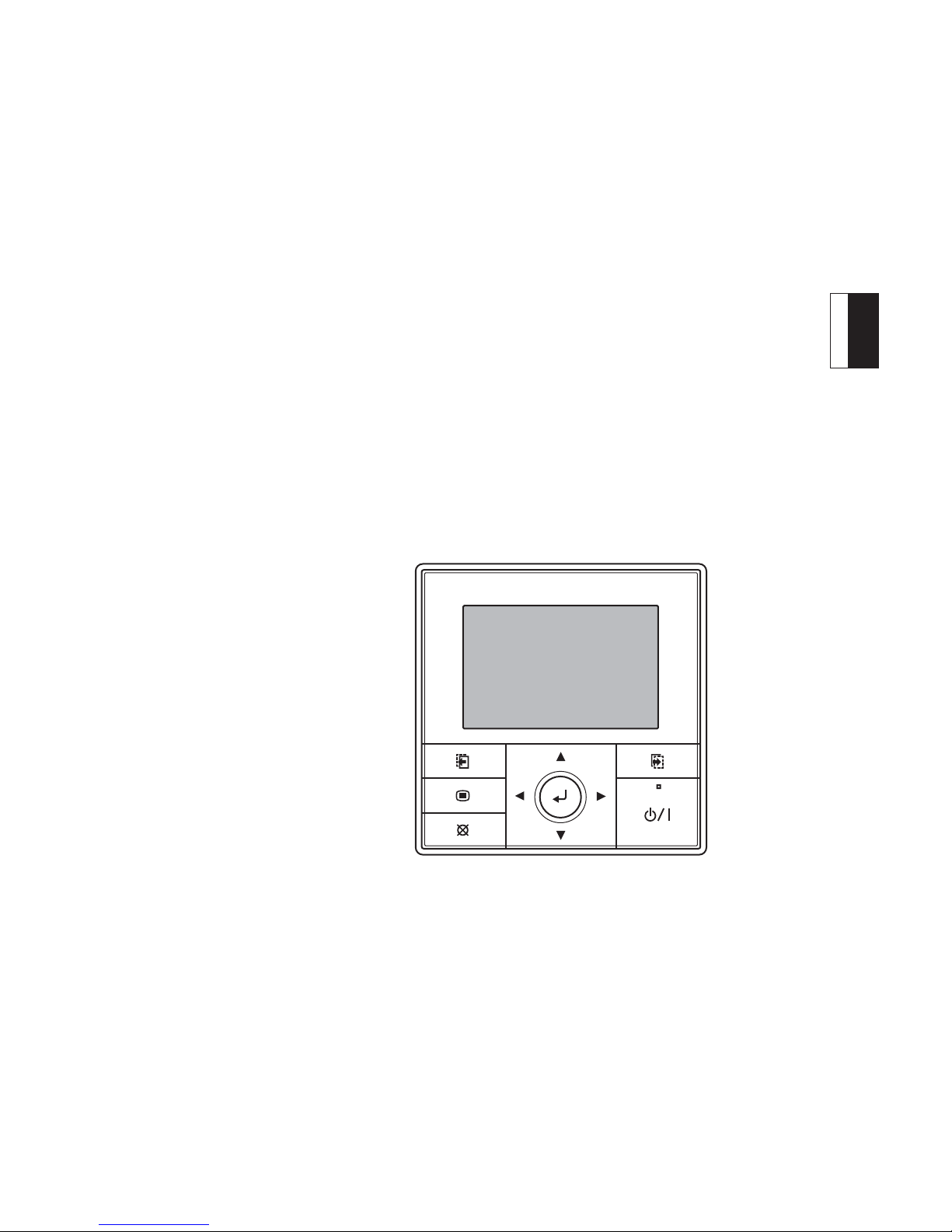
]1
1-3. Name of parts
CAUTION
• Press the button lightly with a finger. It may cause a
failure if pressed with excessive force.
• Do not press the screen too hard. It may cause a failure.
Ex.) “Function” screen
Function
Mo 10:00AM
Min.heat (All) Disable
Economy (All)
O.U. low noise
Schedule select
Back:
Setting:
Disable
Disable
Schedule 1
Operation Schedule
(1)
(2)
(3)
(4)
(6)
(7)
(8)
(5) (9)
(1) Display panel (with backlight) ......................... (See 1-3-1.)
(2) Screen switch button (Left) ............................ (See 1-3-2.)
(3) Menu button ................................................... (See 1-3-3.)
(4) Cancel button ................................................. (See 1-3-4.)
(5) Cursor button ................................................. (See 1-3-5.)
(6) Screen switch button (Right) .......................... (See 1-3-2.)
(7) Power indicator .............................................. (See 1-3-7.)
(8) On/Off button .................................................. (See 1-3-8.)
(9) Enter button .................................................... (See 1-3-6.)
1-3-1. About the Display panel
Display may change depending on the operation or setting.
·
This can set the brightness, contrast and automatic light-off
·
time of the backlight. Refer to [9. SUBMENU SETTING].
This product uses a Bitmap font made and developed by
Ricoh Co.,Ltd.
1-3-2. About the Screen switch button
(Left/Right)
While the screen name or setting items are displayed in the
·
black field under the screen, the screen can be switched
to that screen by pressing the Screen switch button (Left/
Right).
Ex.) “Operation” screen
Operation
Room 1
On-Off
Off
Cancel:
Screen switch
button (Left)
Mode
Cool
OK:
Fan/Min.heat/Economy
Mo 10:00AM
Set temp.
78
Screen switch
button (Right)
°F
Notice
While the backlight is off by the automatic light-off, the
rst button operation does not work and the backlight
illuminates.
While the backlight is set to “Off”, it is effective from the
rst button.
Ex.) “Monitor” screen
Monitor
Room 1
Room 4
Cool
Room 7 Room 8
All
Economy
Min.heat
Menu
Operation
En-3
Room 2 Room 3
Room 5 Room 6
All
O.U.
Low noise
Function
Schedule
Mo 10:00AM
RC prohibit
Schedule
Operation
Room 1
Fan
Min.heat
Off Off
High
Cancel:
OK:
On-Off/Mode/Set temp.
Mo 10:00AM
Economy
Page 5
1-3-3. About the Menu button
1-3-6. About the Enter button
This button is pressed while the “Monitor” screen is
·
displayed, it switches to the “Submenu” screen. For the
details, refer to [9. SUBMENU SETTING].
Submenu
Monitor:
Date/Time
R.C. prohibit
Setting:
Screen
Initial
Mo 10:00AM
1-3-4. About the Cancel button
When this button is pressed while setting, the setting is
·
canceled and returns to the previous screen.
When this button is pressed after setting (or before setting),
·
returns to the previous screen.
The operation when pressing the [Cancel button] is displayed
·
in the lower left of each setting screen.
While setting
This is used for the decision of a selected item or con rming
·
the setting.
The operation when pressing the [Enter button] is displayed
·
at the lower center of each setting screen.
Before setting (or after setting)
Back:
Setting:
XXXXXX XXXXXX
While setting
Cancel:
OK:
XXXXXX XXXXXX
Note
In the operation setting, “OK” blinks when set or changed.
Notice
When switching to another set screen or “Monitor”
screen before the setting is completed, the cancel
confirmation screen is displayed. When canceling the
set, select “Yes” in the [Cursor button (Left/Right)] and
press the [Enter button].
Cancel:
OK:
XXXXXX XXXXXX
After setting (or before setting)
Back:
Setting:
XXXXXX XXXXXX
1-3-5. About the Cursor button
This is used for the selection of a setting item or the setting
·
of set items.
Up
Left
Right
Down
Notice
Press the marked part. It doesn't respond correctly when
diagonally operating it.
]
Setting change will be canceled. OK?
No
Yes
1-3-7. About the Power indicator
This indicator illuminates when one indoor unit or more is
·
operating (Green). It turns off when all indoor units stop.
Notice
An error has occurred when the Power indicator blinks.
Refer to [10. OTHERS].
1-3-8. About the On/Off button
This button switches the air conditioner On/Off. Refer to [5.
·
ON/OFF BUTTON OPERATION].
En-4
Page 6
2. INITIALIZATION
1
2-1. Initial settings
(When starting for the rst time)
CAUTION
• To protect the compressor, turn on the power of the air
conditioning system 12 hours or more before the start of
operations.
Starting the air conditioning system immediately after
power on may cause a failure.
The “Language” screen is displayed, when the start
3
up is completed normally. The display language of this
product is only English. Pressing the [Enter button].
Language
English
OK:
Notice
Below description is the initial setting of the Central Remote Controller when starting for the rst time. Screen
switch method is different from the initial setting except
when starting for the rst time. (Refer to [9. SUBMENU
SETTING]).
Follow the below procedure for the application of power after
the installation and wiring are all completed.
1
(1) Power on the connected outdoor units.
(2) Power on all connected branch boxes.
(Central Remote Controller starts).
Indoor units are registered automatically while activate.
2
Please wait
Notice
When below error screen blinks, communication between the Central Remote Controller and the air conditioning system is not performed.
When [Enter button] is pressed, the “Temp. unit” screen
is displayed.
Switch the unit for temperature “°C” or “°F” with [Cursor
4
button (Up/Down)].
(When [Cancel button] is pressed, it returns to the
“Language” screen.)
Temp. unit
Temp. unit
°F
Cancel: OK:
When [Enter button] is pressed, the “Date” screen is
displayed.
Set the “Day”, “Month” and “Year”.
5
Switch the setting item with [Cursor button (Left/Right)],
and set with [Cursor button (Up/Down)].
(When [Cancel button] is pressed, it returns to the
“Temp. unit” screen.)
Date
Error
code: 12
All power supplies are turned off, and re-check the connection of the Central Remote Controller.
En-5
Day Month Year
01 / 01 / 2010
Friday
Cancel: OK:
When [Enter button] is pressed, the “Time” screen is
displayed.
Page 7
Set the “hour” and “min”.
6
Switch the setting item by [Cursor button (Left/Right)],
and set with [Cursor button (Up/Down)].
(“Min” can be set quickly if the button is pressed continuously.)
(When [Cancel button] is pressed, it returns to the “Date”
screen.)
Time
When setting is completed, select “Yes” with [Cursor
8
button (Left/Right)], and press [Enter button].
When correcting a setting, set it again as it returns to
the “Language” screen when “No” is selected and press
[Enter button].
(If no correction, proceed to the next setting by pressing the [Enter button] without modi cation.)
hour min
10: 00
Cancel: OK:
When [Enter button] is pressed, the “Change display
format” screen is displayed.
AM
Notice
Set the standard time here even for summer time (daylight saving time). Another setting will be made separately. Refer to [9. SUBMENU SETTING].
Set the display format of “Date format” and “Time for-
7
mat”. Switch the setting item with [Cursor button (Left/
Right)] and con rm with the [Cursor button (Up/Down)].
(When [Cancel button] is pressed, it returns to the “Time”
screen.)
Change display format
Date format
Time format
Initial setting will be ended. OK?
No
Initial setting for start-up the rst time completes when
9
[Enter button] is pressed and the “Monitor” screen is
displayed after completion of operation.
Monitor
Off
Room 1
Room 4
Room 2 Room 3
Room 5 Room 6
Yes
Fr 10:00AM
Room 7 Room 8
Menu
Operation
After the test operation, advise the location of each
indoor unit to the users.
Room 1
Function
Schedule
00:00–11:59 AM/PMDay/Month/Year
Cancel: OK:
Note
Following display formats are available for setting.
Date format: Time format:
• Day/Month/Year • 00:00-23:59
• Month/Day/Year • 00:00-11:59 AM/PM
• Year/Month/Day • 12:00-11:59 AM/PM
When [Enter button] is pressed, the “Confirmation”
screen is displayed.
Room 2
Room 3
Room 4
Room 5
Room 6
Room 7
Room 8
Notice
The display number of the indoor units might be skipped
according to the indoor units connection layout.
En-6
Page 8
3. PREPARATION
1
CAUTION
• To protect the compressor, turn on the power of the air
conditioning system 12 hours or more before the start of
operation.
Starting the air conditioning system immediately after
power on may cause a failure.
• Always turn off the breaker when cleaning the remote
controller, air conditioner, or lter.
It may cause injury if operation starts during cleaning.
Notice
Following error message blinks on the Display panel if
power on of the outdoor unit is forgotten or the power to
the indoor units is disconnected.
Error
code: 12
1
3-1. Turning on the power
When turning on the power after the power is cut off during
the off season, follow the below procedure.
(1) Power on the connected outdoor units.
1
(2) Power on all connected branch boxes.
(The Central Remote Controller starts).
Connection of air conditioning system is checked
2
during start-up.
Please wait
When the start-up is completed normally, “Monitor”
3
screen is displayed on the Display panel of the Central
Remote Controller and the system maintains the standby status.
Refer to [4. MONITOR SCREEN] for the “Monitor”
screen.
Refer to [6. OPERATION SETTING] for operation of the
air conditioner.
In this case, immediately cut off all the power and power
on again.
Note
To start the operation smoothly, it is recommended
·
to not cut off the power of the air conditioning system
during the on-season except for cleaning or a fault.
During minimum heat operation, do not cut off the
·
power to the air conditioning system even if leaving
home for a long time.
1
3-2. Checking the time
Check that the current time is displayed correctly on the screen.
(Ask the installer to set the correct time when installing.)
If changing the time or switching the setting for summer time
(daylight saving time), follow the instructions in [9. SUBMENU
SETTING].
Monitor
Off
Menu
Operation
Room 1
Room 4
Room 2 Room 3
Room 5 Room 6
Room 7 Room 8
Function
Mo 10:00AM
Schedule
Monitor
Off
Room 1
Room 4
Room 2 Room 3
Room 5 Room 6
Room 7 Room 8
Menu
Operation
Function
En-7
Mo 10:00AM
Schedule
Page 9
1
f
3-3. About the key lock
A locking function is provided to prevent careless operation
by children or outsiders. Release the lock on the “Monitor”
screen when operating. Refer to [4. MONITOR SCREEN] for
the “Monitor” screen.
4. MONITOR SCREEN
1
1
4-1. About the Monitor screen
Setting status of functions or operating status of each indoor
unit is displayed. This is the basic screen of this control unit.
Monitor
Off
Room 1
Room 4
Room 2 Room 3
Room 5 Room 6
Mo 10:00AM
Room 7 Room 8
Key lock
To lock up:
When the [Cancel button] is pressed for 2 seconds or more
continuously on the “Monitor” screen, all keys are locked, and
“Key lock” is displayed on the screen.
To release the lock:
When the [Cancel button] is pressed for 2 seconds or more
continuously on the “Monitor” screen, the lock is released,
and “Key lock” displayed on the screen turns off.
Cancel button
Note
“Key lock” display blinks when operating it while locked.
Schedule
Mo 10:00AM
RC prohibit
Monitor
Cool
All
Min.heat
Room 1
Room 4
Room 2 Room 3
Room 5 Room 6
Room 7 Room 8
All
Economy
O.U.
Low noise
Menu
Operation
Function
Schedule
4-1-1. Operation mode display
Schedule
Schedule
Mo 10:00AM
RC prohibit
Monitor
Room 1
Room 4
Cool
Room 7 Room 8
All
Economy
Min.heat
Room 2 Room 3
Room 5 Room 6
All
O.U.
Low noise
Menu
Operation
Operating mode is displayed with marks. When all the indoor
units are stopped, “Off” is displayed.
Refer to [6. OPERATION SETTING] for operation mode setting.
Function
Marks of the operation mode
Of
Auto Cool Dry Fan Heat Min.heat All-off
Note
When multiple modes are operated at the same time,
the following are displayed.
Operation mode Displayed mark
“Cool” and Dry, Auto and/or Fan
“Dry” and Auto and/or Fan
“Auto” and Fan
“Heat” and Auto
“Min heat”
Cool
Dry
Auto
Heat
Min.heat
En-8
Page 10

4-1-2. Indoor units display
4-1-3. Function display
Schedule
Mo 10:00AM
RC prohibit
Monitor
Cool
All
Min.heat
Room 1
Room 4
Room 2 Room 3
Room 5 Room 6
Room 7 Room 8
All
Economy
O.U.
Low noise
Menu
Operation
Connected indoor units (Room X) are displayed. Operating
indoor unit is highlighted. For setting operation/stop of the
indoor units, refer to [6. OPERATION SETTING].
Function
Schedule
Room 1 Room 1
Indoor unit under stop Indoor unit under operation
(or under minimum
heat operation)
Notice
•
The indoor unit is set the ON timer
by wireless remote controller, the
indoor unit is displayed under
operation. At that time, the set
of the ON timer will be canceled
when the indoor unit is turned off
from Central remote controller.
Room 1
Schedule
Mo 10:00AM
RC prohibit
Monitor
Cool
All
Min.heat
Room 1
Room 4
Room 2 Room 3
Room 5 Room 6
Room 7 Room 8
All
Economy
O.U.
Low noise
Menu
Operation
The effective set-up functions are displayed with signs. Not
set or invalid settings are not displayed. For details of functions for setting methods, refer to the description in each item.
Function
Schedule
All Min.heat All Economy
O.U. Low noise Schedule
Refer to [7. FUNCTION SETTING]
RC prohibit
Refer to [9. SUBMENU SETTING]
4-1-4. Setting menu
•
The indoor unit displayed like the
right is set from the indoor unit and
outdoor unit to the remote control
prohibition. In this case, operation
and setting cannot be made by
the Central remote controller.
• A blinking indoor unit means an
incorrect combination of operating
mode is set. For details refer to
[6-3-2. Operation mode setting].
• When an error displays alternately,
there is an error with an indoor
unit. Check the error display on
the indoor unit or the standard
remote controller and contact an
authorized service person.
Room 1
Room 1
(Under operation)
Room 1
Room 1
Error
Schedule
Mo 10:00AM
RC prohibit
Monitor
Cool
All
Min.heat
Room 1
Room 4
Room 2 Room 3
Room 5 Room 6
Room 7 Room 8
All
Economy
O.U.
Low noise
Menu
Operation
This is the menu to set the operation or each function. Selected the item with [Cursor button (Left/Right)] and press
the [Enter button], it switches to the operation screen of each
menu.
Function
Schedule
Operation
Settings relating to the operation can be made.
Refer to [6. OPERATION SETTING].
Function
Settings relating to the function can be made.
Refer to [7. FUNCTION SETTING].
Schedule
Setting of pattern for a scheduled operation can be
made.
Refer to [8. SCHEDULE SETTING].
En-9
Page 11

5. ON/OFF BUTTON OPERATION
1
1
5-1. Operation with On/Off button
6. OPERATION SETTING
1
1
6-1. About the Operation setting
The operation starts when the [On/Off button] is pressed
1
once while all indoor units are stopped.
On/Off button
Note
By this operation, the indoor units start operating
·
with the setting (operation mode, fan speed and
temperature) when last operation stopped.
Refer to [6. OPERATION SETTING] if operating
·
selected indoor units, switching the operating mode,
or setting the fan speed and temperature.
When the [On/Off button] is pressed once while operat-
2
ing, all the operating indoor units stop.
Note
When the Minimum heat (All) function is selected, all
indoor units start the minimum heat operation. This is
convenient when going out.
Refer to [7. FUNCTION SETTING] for Minimum heat
(All).
Notice
If the indoor unit is set the ON timer by wireless remote
controller, the indoor unit ON timer will be canceled
when stop to press the [On/Off button].
These can vary the operation or operation settings. Available
settings or operations are as follows.
On/Off operation
On/Off for all indoor units or a selected indoor unit
can be set.
After selecting the operating indoor units, follow the
instructions in [6-3-1. On/Off operation].
Operation mode setting
Operating mode for all indoor units or a selected
indoor unit can be set.
After selecting the setting indoor units, follow the
instructions in [6-3-2. Operation mode setting].
Room temperature setting
Temperature for all indoor units or a selected indoor
unit can be set.
After selecting the setting indoor units, follow the
instructions in [6-3-3. Room temperature setting].
Fan speed setting
Fan speed of each selected indoor unit can be set.
After selecting the setting indoor units, follow the
instructions in [6-3-4. Fan speed setting].
Minimum heat setting
Minimum heat operation of each selected indoor
unit can be set.
After selecting the setting indoor unit, follow the
instructions in [6-3-5. Minimum heat setting].
If setting minimum heat operation for all indoor
units, refer to [7. FUNCTION SETTING].
Economy setting
Economy setting of each selected indoor unit can
be set.
After selecting the setting indoor units, follow the
instructions in [6-3-6. Economy setting].
When economy operation is set for all indoor units,
follow the instructions in [7. FUNCTION SETTING].
En-10
Page 12

11
6-2. Switching to the “Operation” screen
When selecting “Operation” from the Menu on the “Monitor”
1
screen with [Cursor button (Left/Right)] and [Enter button]
is pressed, “Operation (unit select)” screen is displayed.
After setting, screen returns to the “Operation (unit
3
select)” screen. To terminate the setting, press the [Cancel
button] to return to the Monitor screen.
6-2-2.
Operation/setting of each indoor unit
Monitor
Off
Room 1
Room 4
Room 2 Room 3
Room 5 Room 6
Mo 10:00AM
Room 7 Room 8
Menu
Operation
Proceed to [6-2-1. Operation/setting of all indoor units
2
at once] or [6-2-2. Operation/setting of each indoor unit]
6-2-1.
1
Operation/setting of all indoor units at once
Select “Select all” with the [Cursor button], and press
the [Enter button].
Operation
Select
all
Back:
Room 1
Off
Room 4
Off
Room 7
Off
Function
Room 2
Off
Room 5
Off
Room 8
Off
Setting:
Schedule
Mo 10:00AM
Room 3
Off
Room 6
Off
Schedule Function
“Operation” screen is displayed.
2
Operation
Mo 10:00AM
ALL
On-Off
Off
Cancel:
Proceed according to the following operation/setting.
6-3-1. On/Off operation
6-3-2. Operation mode setting
6-3-3. Room temperature setting
Mode
Cool
OK:
Set temp.
78
°F
S
elect an indoor unit (Room X) with the [Cursor button]
1
and press the [Enter button].
Operation
Select
all
Room 1
Off
Room 4
Room 2
Room 5
Off
Room 7
Room 8
Off
Back:
.
Display of indoor unit under operation
Auto,Cool,Dry or
Heat operation
Schedule Function
°F
78
°F
78
Economy
operation
Setting:
Fan operation
78
Test operation
Notice
• The indoor unit is set the ON timer
by wireless remote controller, the
indoor unit is displayed under
operation. At that time, the set of the ON timer will be
canceled when the indoor unit is turned off from Central
remote controller.
• If the operating mode sign or
“Min.Heat” blinks, an incorrect
combination of operating modes
has been set.
Refer to [6-3-2. Operation mode
setting].
• The indoor unit displayed like the
right is set from the indoor unit
and outdoor unit to the remote
control prohibition. In this case,
operation and setting cannot
be made by the Central remote controller.
indoor unit is selected, below indication is displayed
on the lower screen, and cannot proceed to the next
operation.
Off
Off
Off
°F
Mo 10:00AM
Room 3
Off
Room 6
Off
Min.heat
Minimum heat
operation
°F
78
78
Min.heat
Room 2
Off
When this
°F
Notice
When all indoor units are operated/set at once, [Fan
speed setting], [Minimum heat setting] and [Economy
setting] cannot be set. Set in each indoor unit.
En-11
Back:
Op. restricted:
Schedule Function
This indoor unit cannot be selected by the operation
of “Select all”.
Page 13

“Operation” screen is displayed. The screen consists of
2
2 pages, and can be switched by pressing the [Screen
switch button (Left/Right)].
Operation
Room 1
On-Off
Mode
Mo 10:00AM
Set temp.
11
6-3. Operation setting
6-3-1. On/Off operation
Select “On-Of
1
“On” or “Off” with [Cursor button (Up/Down)].
f” with [Cursor button (Left/Right)], and set
78
Off
Cancel:
Screen switch
button (Left)
Operation
Room 1
Fan
High
Cancel:
On-Off/Mode/Set temp.
Proceed according to the following operation/setting.
6-3-1. On/Off operation
6-3-2. Operation mode setting
6-3-3. Room temperature setting
6-3-4. Fan speed setting
6-3-5. Minimum heat setting
6-3-6. Economy setting
After setting, screen returns to the indoor unit selection
3
screen. When setting another indoor unit, select the indoor unit.
Cool
OK:
Fan/Min.heat/Economy
Screen switch
button (Right)
Min.heat
Off Off
OK:
°F
Mo 10:00AM
Economy
Operation
Room 1
On-Off
On
Cancel:
On/Off marks
Other operation setting items can be set continuously.
2
To complete the setting, press the [Enter button], then it
returns to the “Operation (unit select)” screen.
Mode
Cool
OK:
Fan/Min.heat/Economy
OffOn
Mo 10:00AM
Set temp.
78
°F
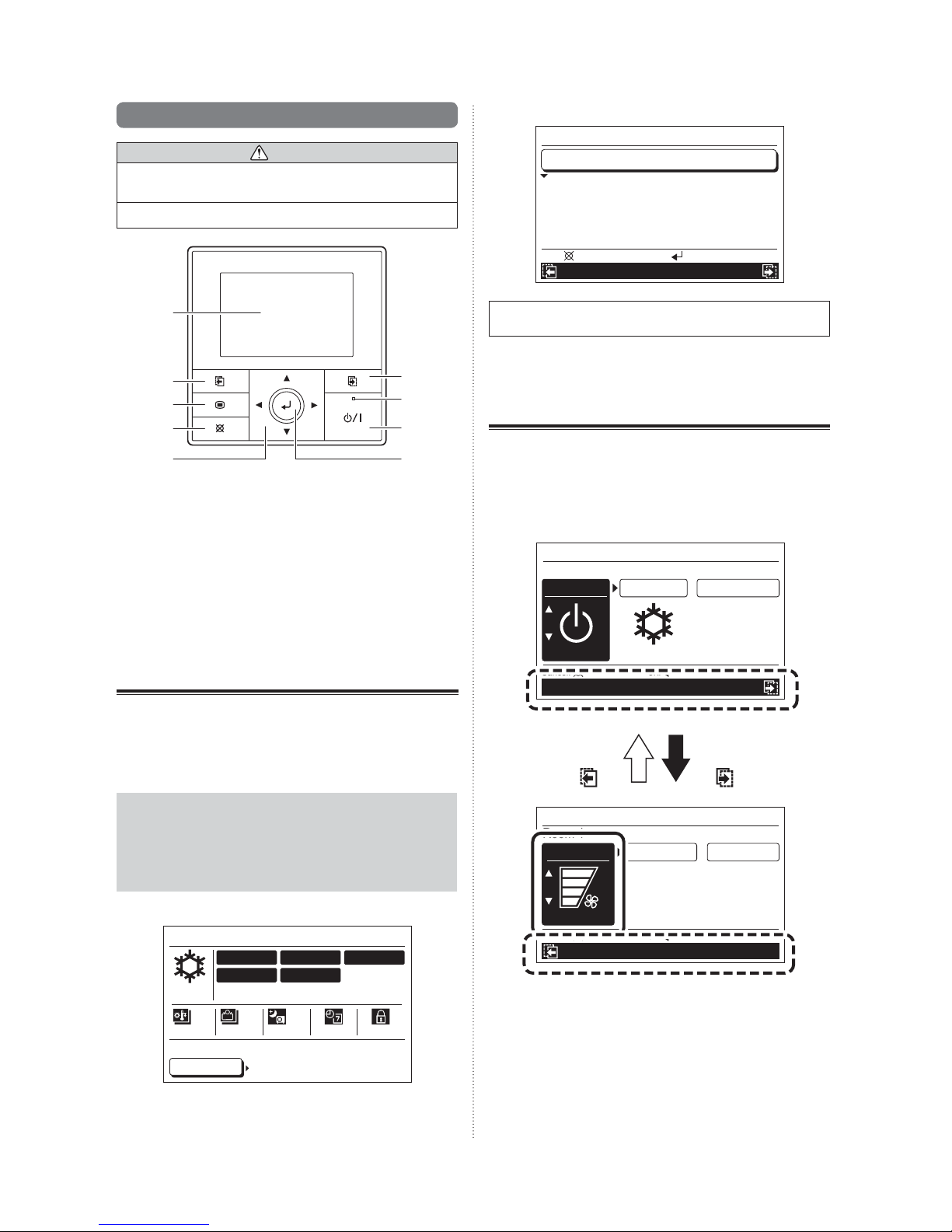
6-3-2. Operation mode setting
Select “Mode” with the [Cursor button (Left/Right)], and
1
set the operation mode with the [Cursor button (Up/
Down)].
Operation
Room 1
On-Off
Mode
Mo 10:00AM
Set temp.
If terminating the setting, press the [Cancel button] to
return to the “Monitor” screen.
78
On
Cancel:
Operation mode marks
Auto Cool Dry Fan Heat
Other operation setting items can be set continuously.
2
To complete the setting, press the [Enter button], then it
returns to the “Operation (unit select)” screen.
Cool
OK:
Fan/Min.heat/Economy
°F
En-12
Page 14

Notice
When setting the operating mode for each indoor unit,
setting combinations are restricted. Possible setting
combinations are as follows:
Conditions
One indoor unit or more is under the
Cool operation
One indoor unit or more is under the
Dry operation
One indoor unit or more is under the
Heat operation
When the Cool operation mode is
xed *
When the Heat operation mode is
xed *
* Only where the signal is transmitted from the outdoor
unit through the external input. For details, contact
your authorized service personnel.
Possible setting
combination
Cool, Dry
Fan, Auto
Cool, Dry
Fan, Auto
Heat, Auto
Cool, Dry
Fan, Auto
Heat, Auto
11
Other operation setting items can be set continuously.
2
To complete the setting, press the [Enter button], then it
returns to the “Operation (unit select)” screen.
6-3-4. Fan speed setting
Select “Fan” with the [Cursor button (Left/Right)], and set
1
the fan speed with the [Cursor button (Up/Down)].
Operation
Room 1
Fan
High
Cancel:
On-Off/Mode/Set temp.
Fan speed marks
Min.heat
Off Off
OK:
Mo 10:00AM
Economy
6-3-3. Room temperature setting
Select “Set temp.” with the [Cursor button (Left/Right)]
1
and set the room temperature with the [Cursor button (Up/
Down)].
Operation
Mo 10:00AM
Room 1
On-Off
Cancel:
On
Mode
Cool
OK:
Set temp.
78
°F
Fan/Min.heat/Economy
Notice
• Possible temperature setting ranges in the operation
mode are as follows:
Cool, Dry, Auto ............... 64 to 88 °F (18 to 30 °C)
Heat ............................... 60 to 88 °F (16 to 30 °C)
• When operation mode is set to “Fan”, Room temperature cannot be set. (“Set temp.” cannot be
selected.)
AutoQuietLowMedHigh
Notice
When the operation mode is set to “Dry”, Fan speed
switches to “Auto”. (Fan speed cannot be selected).
Other operation setting items can be set continuously.
2
To complete the setting, press the [Enter button], then it
returns to the “Operation (unit select)” screen.
6-3-5. Minimum heat setting
Select “Min.heat” with the [Cursor button (Left/Right)]
1
and set “On” with the [Cursor button (Up/Down)], Minimum heat operation starts.
Operation
Room 1
Fan
Min.heat Economy
Mo 10:00AM
• If the operation mode is set to “Auto” and the room
temperature or setting temperature is significantly
different in each room, each indoor unit may have an
impossible setting combination. In this case, set to
possible settings operation mode except “Auto”.
En-13
High On
Cancel:
OK:
On-Off/Mode/Set temp.
Page 15

Notice
• When “Min.heat” is set to “On” at the operating
indoor unit, the operation stops and starts the
Minimum heat operation. (“On-Off” turns to “Off”).
• When “On-Off” is set to “On” after “Min.heat” is set
to “On”, Minimum heat operation stops. (“Min.heat”
turns to “Off”).
• While “Minimum heat (All)” is set to “Enable” in
function setting, cannot release by the operation
setting. When release it, set “Minimum heat (All)” to
“Disable” in function setting.
Other operation setting items can be set continuously.
2
To complete the setting, press the [Enter button], then it
returns to the “Operation (unit select)” screen.
6-3-6. Economy setting
Select “Economy” with the [Cursor button (Left/Right)]
1
and set “On” with the [Cursor button (Up/Down)].
Operation
Room 1
Fan
Off
High
Cancel:
OK:
On-Off/Mode/Set temp.
Mo 10:00AM
EconomyMin.heat
On
Notice
• While “Economy (All)” is set to “Enable” in function
setting, Economy cannot be turned to “Off” by the
operation setting or the standard remote controller.
If necessary, set “Economy (All)” to “Disable” in
function setting.
• When in the Minimum heat operation, Economy
setting is not displayed (It is not possible to set it).
Other operation setting items can be set continuously.
2
To complete the setting, press the [Enter button], then it
returns to the “Operation (unit select)” screen.
7. FUNCTION SETTING
1
1
7-1. About the Function setting
Functions relating to the operation can be set. Available settings or operations are as follows:
Minimum heat (All) setting
Enable or disable Minimum heat (All) can be set. If set to
enable, all indoor units start the Minimum heat operation
which is stopped by pressing the [On/Off button] on the
Central remote controller.
Refer to [7-3-1. Minimum heat (All) setting].
If each indoor unit is set to Minimum heat operation, set
according to the instructions in [6. OPERATION SETTING].
Economy (All) setting
Enable or disable Economy (All) can be set. If set to enable, all indoor and outdoor units operate in economy operation mode.
Refer to [7-3-2. Economy (All) setting]
If each indoor unit is set to economy operation, follow the
instructions in [6. OPERATION SETTING].
Outdoor unit low noise operation setting
Enable or disable of the low noise operation of the outdoor
unit and the period of time can be set. If set to enable, the
outdoor units operate in the low noise operation mode during the set period of time.
Refer to [7-3-3. Outdoor unit low noise operation setting].
Schedule select
Selecting schedule pattern when the schedule timer operation is applied and the days of the week can be set when
the schedule timer operation is not applied temporarily.
Refer to [7-3-4. Schedule select].
Pre-setting of schedule pattern is required. To set the
schedule pattern, follow the instructions in [8. SCHEDULE
SETTING].
1
1
7-2. Switching to the “Function” screen
If “Function” is selected with the [Cursor button (Left/
1
right)] from the Monitor screen menu, and [Enter
button] is pressed, “Function” screen is displayed.
Monitor
Off
Room 1
Room 4
Room 2 Room 3
Room 5 Room 6
Room 7 Room 8
Mo 10:00AM
Menu
Operation
Proceed to [7-3. Function setting].
2
Function
Schedule
En-14
Page 16

1
1
7-3. Function setting
7-3-2. Economy (All) setting
7-3-1. Minimum heat (All) setting
Select “Min.heat (All)” with the [Cursor button (Up/
1
Down)] and press the [Enter button].
Function
Min.heat (All) Disable
Economy (All)
O.U. low noise
Schedule select
Back:
Setting:
Operation Schedule
Since the setting items are highlighted, set “Enable” or
2
“Disable” with the [Cursor button (Up/Down)] and press
the [Enter button].
Function
Min.heat (All) Enable
Economy (All)
O.U. low noise
Schedule select
Cancel: OK:
Operation Schedule
Mo 10:00AM
Disable
Disable
Schedule 1
Mo 10:00AM
Disable
Disable
Schedule 1
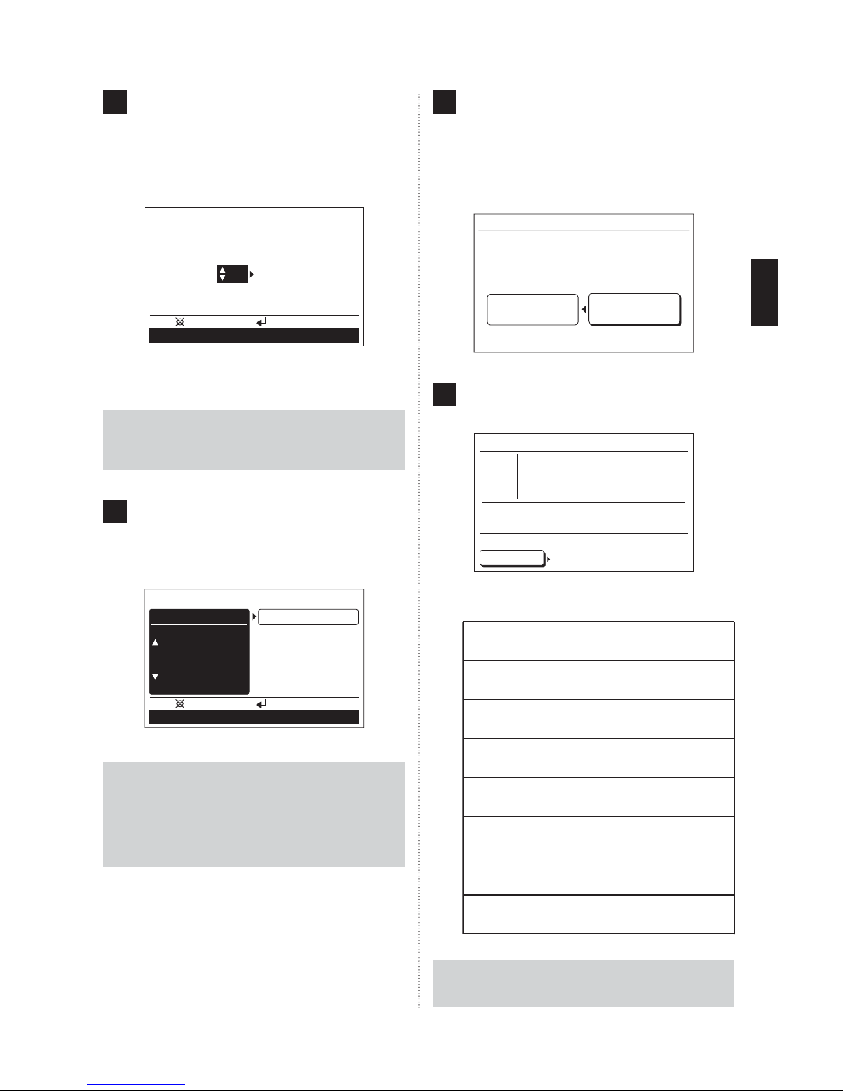
Select “Economy (All)” with the [Cursor button (Up/
1
Down)] and press the [Enter button].
Function
Min.heat (All)
Economy (All)
O.U. low noise
Schedule select
Back:
Setting:
Mo 10:00AM
Disable
Disable
Disable
Schedule 1
Operation Schedule
Since the setting items are highlighted, set “Enable” or
2
“Disable” with the [Cursor button (Up/Down)] and press
the [Enter button].
Function
Min.heat (All)
Economy (All)
O.U. low noise
Schedule select
Cancel: OK:
Mo 10:00AM
Disable
Enable
Disable
Schedule 1
Operation Schedule
Reversed display release. When “Enable” is set, the
3
indication of function is displayed in the upper part of the
screen, and all indoor units start the Minimum heat operation which is stopped by pressing the [On/Off button]
on the Central remote controller.
Function
Mo 10:00AM
Min.heat (All) Enable
Economy (All)
O.U. low noise
Schedule select
Back:
Setting:
Disable
Disable
Schedule 1
Operation Schedule
To set other items, select the item with the [Cursor but-
ton (Up/Down)].
To complete the setting, the display returns to the
4
“Monitor” screen when the [Menu button] is pressed.
Notice
• This function is enabled only when stopped by
pressing the [On/Off button] on the Central remote
controller.
• When minimum heat (All) operation is stopped, set
to “Disable” and minimum heat set to “off” in the
operation setting of each indoor unit. Refer to [6.
OPERATION SETTING].
Reversed display release. When “Enable” is set, the
3
indication of function is displayed in the upper part of
screen, and all indoor units start in Economy operation
mode.
Function
Min.heat (All)
Economy (All)
O.U. low noise
Schedule select
Back:
Setting:
Mo 10:00AM
Disable
Enable
Disable
Schedule 1
Operation Schedule
To set other items, select the item with the [Cursor but-
ton (Up/Down)].
To complete the setting, the display returns to the
4
“Monitor” screen when the [Menu button] is pressed.
Notice
When Economy (All) is set to “Enable”, Economy mode
cannot be released by the Operation setting and the
standard remote controller.
En-15
Page 17

7-3-3. Outdoor unit low noise operation
setting
Select “O.U. low noise” with the [Cursor button (Up/
1
Down)] and press the [Enter button].
Function
Min. heat (All)
Economy (All) Disable
O.U. low noise Disable
Schedule select
Back:
Operation Schedule
Setting:
Mo 10:00AM
Disable
Schedule 1
“Hour” of “Start time” is highlighted. Set the “Hour” with
5
the [Cursor button (Up/down)].
:
– –
Mo 10:00AM
Enable
AM
O.U. low noise
O.U. low noise
Time setting
Start time Stop time
:
AM –
– –
– –
Cancel: OK:
– –
Schedule select
Notice
Display of time is the same style as the setting. Refer to
[9. SUBMENU SETTING].
O.U. low noise screen is displayed. Select “O.U. low
2
noise” with the [Cursor button (Up/Down)] and press
the [Enter button].
:
:
– –
Mo 10:00AM
– –
AM
Mo 10:00AM
Enable
AM
O.U. low noise
O.U. low noise Disable
Time setting
Start time Stop time
:
:
– –
AM –
– –
Setting:
AM –
– –
Schedule select
– –
Schedule select
– –
Back:
Since the setting items are highlighted, set “Enable”
3
with the [Cursor button (Up/Down)], and press the
[Enter button]. Reversed display of “O.U. low noise” is
released.
O.U. low noise
O.U. low noise
Time setting
Start time Stop time
– –
Cancel: OK:
Select “Minute” with the [Cursor button (Left/Right)],
6
and set by the same procedure as “Hour”.
(Setting can be made in unit for 5 minutes.)
:
– –
Mo 10:00AM
Enable
AM
Mo 10:00AM
AM
O.U. low noise
O.U. low noise
Time setting
Start time Stop time
:
: 00
PM –
– –
PM –
Setting:
– –
Schedule select
7 : 00
Schedule select
10
Cancel: OK:
Set “Hour” and “Minute” for the “Stop time” continuously.
When xed by pressing the [Enter button], the indica-
7
tion of function is displayed in the upper part of the
screen.
O.U. low noise
O.U. low noise Enable
Time setting
Start time Stop time
10
Back:
Set a time for low noise operation. Select “Time setting”
4
with the [Cursor button (Up/Down)] and press the [Enter
button].
O.U. low noise
O.U. low noise
Time setting
Start time Stop time
:
– –
AM –
Setting:
– –
Schedule select
– –
Back:
:
– –
Mo 10:00AM
Enable
AM
To set other items, select the item with the [Cursor but-
ton (Up/Down)].
To return to the “Function” screen, press the [Cancel
8
button].
To complete the setting, the display returns to the
“Monitor” screen when the [Menu button] is pressed.
Notice
• Set “Hour” and “Minute” together with “Start time”
and “Stop time”. (It does not operate with an
incomplete setting.)
• Do not set the same time for the “Start time” and “Stop
time”. (It does not operate.)
En-16
Page 18

7-3-4. Schedule select
Select “Schedule select” with the [Cursor button (Up/
1
Down)] and press the [Enter button].
Function
Min. heat (All)
Economy (All) Disable
O.U. low noise
Schedule select Disable
Back:
Setting:
Operation Schedule
Schedule select screen is displayed.
2
Select “Schedule” with the [Cursor button (Up/Down)]
and press the [Enter button].
Mo 10:00AM
Disable
Disable
If there are inapplicable days in the schedule timer
4
operation, select “Day off” with the [Cursor button (Up/
Down)] and press the [Enter button].
Schedule select
Mo 10:00AM
Schedule Schedule 1
Day off
Su Mo Tu We Th Fr Sa
Back:
Setting:
O.U. low noise
Notice
This setting is released after once effected. Use this function when the schedule operation is not performed such as
on holidays. The schedule operation is enabled only after
set it.
Schedule select
Mo 10:00AM
Schedule Disable
Day off
Su
Mo Tu We Th Fr Sa
Cancel:
OK:
O.U. low noise
Since the setting item is highlighted, select the applica-
3
ble schedule name with the [Cursor button (Up/Down)]
and press the [Enter button].
Schedule select
Schedule
Mo 10:00AM
Schedule 1
Day off
Su
Mo Tu We Th Fr Sa
Cancel:
OK:
O.U. low noise
When “Disable” is selected, schedule timer operation is
not performed.
When the [Enter button] is pressed, reversed display
of the setting item is released and the indication of
function is displayed in the upper part of the screen.
As the days of the week are highlighted, select appli-
5
cable days with the [Cursor button (Left/Right)] and enter the check mark with the [Cursor button (Up/Down)].
Multiple days in a week can be set.
Schedule select
Schedule
Mo 10:00AM
Schedule 1
Day off
Mo Tu We Th Fr Sa
Su
Cancel:
OK:
O.U. low noise
Notice
When schedule on a day of the week is not set in [8.
SCHEDULE SETTING], schedule operation is not performed even if “Day off” is not checked.
When the [Enter button] is pressed, the reversed dis-
6
play is released.
Schedule select
Schedule Schedule 1
Day off
Su Mo Tu We Th Fr Sa
Mo 10:00AM
Schedule select
Notice
If the indication of function is not displayed in the upper
part of the screen, although [Enter button] is pressed after
“Schedule 1” or “Schedule 2” is set, schedule setting is not
effective or not set. Refer to [8. SCHEDULE SETTING].
En-17
Mo 10:00AM
Schedule 1
Back:
Setting:
O.U. low noise
To return to the “Function” screen, press the [Cancel
7
button].
To complete the setting, the display returns to the
“Monitor” screen when the [Menu button] is pressed.
Page 19

8. SCHEDULE SETTING
1
1
8-1. About the Schedule setting
8-1-1. About the Schedule name
Schedule pattern can be set for each schedule name “Schedule 1” and “Schedule 2”. These cannot be applied to each
indoor unit simultaneously. Use it such as for “Summer” or
“Winter”.
1
8-2. Switching to the “Schedule” screen
If “Schedule” is selected with the [Cursor button (Left/
1
Right)] from the “Monitor” screen menu, and the [Enter
button] is pressed, the “Schedule (unit select)” screen
is displayed.
Monitor
Off
Room 1
Room 4
Room 2 Room 3
Room 5 Room 6
Room 7 Room 8
Mon 10:00AM
8-1-2. About the setting of the time and
operations
Operations up to 4 times a day can be set. Set the pattern
according to the purpose and daily routines.
Ex. 1) On and Off once a day
Time 1
On
Ex. 2) On and Off twice a day
Time 1 Time 2
On On OffOff
Ex. 3) Change the temperature while operating
Time 1
On Off
Ex. 4) Prevention to forget turning off
Time 1
Switching on by using the standard remote controller.
Temperature change
Time 2
Time 2
Time 3
Time 3
Off OffOffOff
Time 2
Off
Time 4
Time 3
Time 4
Menu
Operation
Proceed to [8-2-1. Setting of the same schedule for all
2
indoor units] or [8-2-2. Setting of the schedule for each
indoor unit].
Function
Schedule
8-2-1. Setting of the same schedule for
all indoor units
Select “Select all” with the [Cursor button] and press
1
the [Enter button].
Schedule
Select
all
Back:
Room 1
Disable
Room 4
Disable
Room 7
Disable
Room 2
Disable
Room 5
Disable
Room 8
Disable
Setting:
Function Operation
“Schedule” screen is displayed. Proceed to [8-3-1. Se-
2
lection of schedule name].
Mo 10:00AM
Room 3
Disable
Room 6
Disable
Ex. 5) Operation during the night
Time 1
Off
Time 2
On OnOff
One day
Time 1 Time 2
8-2-2. Setting of the schedule for each
indoor unit
Select the indoor unit (Room X) to be set with the [Cursor
1
button] and press the [Enter button].
Schedule
Select
all
Back:
Room 1
Disable
Room 4
Disable
Room 7
Disable
Room 2
Disable
Room 5
Disable
Room 8
Disable
Setting:
Function Operation
“Schedule” screen is displayed. Proceed to [8-3-1. Se-
2
lection of schedule name].
Mo 10:00AM
Room 3
Disable
Room 6
Disable
En-18
Page 20

Note
If selected indoor units are set up individually, it is necessary to set each individually. As other methods, after all
indoor units are set by the same schedule, each indoor
unit is changed in the setting or deleted.
When Schedule name is selected, proceed to [8-3-2.
2
Setting of Enable/Disable of schedule].
8-3-2. Setting of Enable/Disable of
schedule
1
8-3. Schedule setting
8-3-1. Selection of schedule name
Select the relevant schedule name (“Schedule 1” or
1
“Schedule 2”) with the [Screen switch button (Left/
Right)].
Check the schedule name
Schedule 1
Mo 10:00AM
Room 1
Disable
Time
Back:
Su Mo Tu We Th Fr Sa
1 – –
:
Day
End
– – – – – – – – – –°F
2 – –
:
– – – – – – – – – –°F
3 – –
:
– – – – – – – – – –°F
4 – –
:
– – – – – – – – – –°F
Setting:
Schedule 2
Screen switch
button (Left)
Schedule 2
Screen switch
button (Right)
Mo 10:00AM
Room 1
Disable
Time
Back:
Su Mo Tu We Th Fr Sa
1 – –
:
Day
End
– – – – – – – – – –°F
2 – –
:
– – – – – – – – – –°F
3 – –
:
– – – – – – – – – –°F
4 – –
:
– – – – – – – – – –°F
Setting:
Schedule 1
Notice
• When “Schedule select” is set, it is displayed from
the selected schedule. Refer to [7. FUNCTION
SETTING].
• “Schedule 1” and “Schedule 2” cannot be applied to
each indoor unit simultaneously.
Make sure to set the same schedule name when
applying the schedule at the same time.
Note
In this screen, the current day of the week is displayed
on the front side.
Setting of each day in the week can be checked by
pressing the [Cursor button (Left/Right)].
Select “Disable” (or “Enable”) with the [Cursor button
1
(Up/Down)] and press the [Enter button].
Schedule 1
Mo 10:00AM
Room 1
Disable
Time
Back:
Su Mo Tu We Th Fr Sa
1 – –
:
Day
End
– – – – – – – – – –°F
2 – –
:
– – – – – – – – – –°F
3 – –
:
– – – – – – – – – –°F
4 – –
:
– – – – – – – – – –°F
Setting:
Schedule 2
As “Disable” (or “Enable”) is highlighted, set “Enable” (or
2
“Disable”) with the [Cursor button (Up/Down)].
Schedule 1
Mo 10:00AM
Room 1
Enable
Time
Cancel:
Su Mo Tu We Th Fr Sa
1 – –
:
Day
End
– – – – – – – – – –°F
2 – –
:
– – – – – – – – – –°F
3 – –
:
– – – – – – – – – –°F
4 – –
:
– – – – – – – – – –°F
Setting:
Schedule 2
When xed by pressing [Enter button], reversed display
is released.
When set to “Enable”, proceed to [8-3-3. Selection of
the day of the week].
Note
• Set to “Enable” when schedule operation is performed. When releasing the schedule operation temporarily, set to “Disable”.
• If each indoor unit is set, only the indoor units are
set to “Enable”, schedule operation is performed.
• When shipped from the factory, all the indoor units
are set to “Disable”.
Notice
When only the switch of “Enable” or “Disable” was set,
select “End” with the [Cursor button (Up/Down)] and
press the [Enter button], the setting is completed.
En-19
Page 21

8-3-3. Selection of the day of the week
The day of the week for schedule timer operation can be
selected.
Select “Day” with the [Cursor button (Up/Down)] and
1
press the [Enter button].
Schedule 1
Room 1
Disable
Time
Cancel:
Current day of the week is selected.
2
Su Mo Tu We Th Fr Sa
1 – –
:
Day
End
– – – – – – – – – –°F
2 – –
:
– – – – – – – – – –°F
3 – –
:
– – – – – – – – – –°F
4 – –
:
– – – – – – – – – –°F
Setting:
Mo 10:00AM
Schedule 2
When the selection of the day of the week is completed,
4
press the [Enter button].
Reversed display is released, and only the selected
days of the week are displayed.
Schedule 1
Mo 10:00AM
Room 1
Disable
Day
Time
End
Cancel:
Mo Tu We Th Fr
1 – –
:
– – – – – – – – – –°F
2 – –
:
– – – – – – – – – –°F
3 – –
:
– – – – – – – – – –°F
4 – –
:
– – – – – – – – – –°F
Setting:
Schedule 2
Proceed to [8-3-4. Setting of the time and operation].
Note
If changing a previous scheduled setting, setting of the
time is required again if the days of the week (or the day
of the week if the time is not set) with a different time
setting are selected at the same time.
Schedule 1
Mo 10:00AM
Room 1
Disable
Day
Time
End
Cancel:
Su Mo Tu We Th Fr
1 – –
:
– – – – – – – – – –°F
2 – –
:
– – – – – – – – – –°F
3 – –
:
– – – – – – – – – –°F
4 – –
:
– – – – – – – – – –°F
OK
:
Sa
Select:
Schedule 2
Select the day of the week for the schedule timer ope-
3
ration with the [Cursor button (Left/Right)] and set with
the [Cursor button (Up/Down)]. The setting day of the
week is highlighted.
Schedule 1
Mo 10:00AM
Room 1
Disable
Day
Time
End
Cancel:
Su Mo Tu We Th Fr
1 – –
:
– – – – – – – – – –°F
2 – –
:
– – – – – – – – – –°F
3 – –
:
– – – – – – – – – –°F
4 – –
:
– – – – – – – – – –°F
OK
:
Sa
Select:
Schedule 2
Note
Set all the applicable days of the week for the same
schedule operation.
8-3-4. Setting of the time and operations
Time and operations can be set. Operation at 4 times in a day
can be set.
Select “Time” with the [Cursor button (Up/Down)] and
1
press the [Enter button].
Schedule 1
Room 1
Disable
Day
Time
End
Cancel:
“1” is highlighted. The time and operation can be set to
2
1 ~ 4.
Mo Tu We Th Fr
1 – –
:
– – – – – – – – – –°F
2 – –
:
– – – – – – – – – –°F
3 – –
:
– – – – – – – – – –°F
4 – –
:
– – – – – – – – – –°F
Setting:
Schedule 1
Room 1
Disable
Day
Time
End
Delete: Push for two seconds
Mo Tu We Th Fr
1 – –
:
– – – – – – – – – –
2 – –
:
– – – – – – – – – –
3 – –
:
– – – – – – – – – –
4 – –
:
– – – – – – – – – –
Mo 10:00AM
Schedule 2
Mo 10:00AM
OK
:
Schedule 2
°F
°F
°F
°F
Move to “Hour” by pressing the [Cursor button (Right)].
Note
If 1 ~ 4 is selected, all data already stored is erased when
the [Cancel button] is pressed for 2 seconds or longer.
En-20
Page 22

“Hour” is highlighted. Set the “Hour” with the [Cursor
3
button (Up/Down)].
“On/Off” is highlighted. Set “On” or “Off” with the [Cursor
5
button (Up/Down)].
Schedule 1
Mo 10:00AM
Room 1
Disable
Day
Time
End
Cancel:
Mo Tu We Th Fr
1 6
– – – – –
2 – –
:
– – – – –
3 – –
:
– – – – –
4 – –
:
– – – – –
OK
:
Schedule 2
When “Hour” is set, move to “Minute” by pressing the
[Cursor button (Right)].
“Minute” is highlighted. Set the “Minute” with the [Cursor
4
button (Up/Down)]. (Setting can be completed quickly if
the button is pressed continuously.)
Schedule 1
Mo 10:00AM
Room 1
Disable
Day
Time
End
Cancel:
Mo Tu We Th Fr
1 6 00
2 – –
:
3 – –
:
4 – –
:
– – –
– – – – –
– – – – –
– – – – –
OK
:
Schedule 2
Schedule 1
Mo 10:00AM
Room 1
Disable
Day
Time
End
Cancel:
Mo Tu We Th Fr
1
6:00 AM On
2 – –
:
– – – – –
3 – –
:
– – – – –
4 – –
:
– – – – –
OK
:
– – – – –°F
Schedule 2
When “On” is set, move to “Operation mode” by press-
ing the [Cursor button (Right)].
When “Off” is set, it is not required to set the “Operation
mode” and “Temperature” setting. (It cannot be set.)
“Operation mode” is highlighted. Set the “Operation
6
mode” with the [Cursor button (Up/Down)].
Schedule 1
Mo 10:00AM
Room 1
Disable
Day
Time
End
Cancel:
Mo Tu We Th Fr
1
6:00 AM On Cool
2 – –
:
– – – – –
3 – –
:
– – – – –
4 – –
:
– – – – –
OK
:
– –°F
Schedule 2
If the time is set for 24 hours indication, move to “On/
Off” by pressing the [Cursor button (Right)].
If the time is set for AM/PM indication, move to “AM/
PM” by pressing the [Cursor button (Right)].
Set “AM” or “PM” with the [Cursor button (Up/Down)].
Schedule 1
Mo 10:00AM
Room 1
Disable
Day
Time
End
Cancel:
Mo Tu We Th Fr
1
6:00 AM
2 – –
3 – –
4 – –
:
:
:
– – –
– – – – –
– – – – –
– – – – –
OK
:
Schedule 2
When “AM/PM” is set, move to “On/Off” by pressing the
[Cursor button (Right)].
Notice
Display of time is the same style as the setting. Refer to
[9. SUBMENU SETTING].
When “Operation mode” is set, move to “Temperature”
with the [Cursor button (Right)].
Notice
Operation mode is set to Cool, Dry, Heat, Auto. The
possible simultaneous operation combinations are restricted. Refer to [6-3-2. Operation mode setting].
“Temperature” is highlighted. Set “Temperature” with
7
the [Cursor button (Up/Down)].
Schedule 1
Mo 10:00AM
Room 1
Disable
Day
Time
End
Cancel:
Mo Tu We Th Fr
1
6:00 AM On Cool 82°F
2 – –
:
– – – – –
:
– – – – –
3 – –
4 – –
:
– – – – –
OK
:
Schedule 2
Notice
Possible temperature setting ranges are as follows:
· Cool, Dry, Auto ................. 64 to 88 °F (18 to 30 °C)
· Heat ................................. 60 to 88 °F (16 to 30 °C)
En-21
Page 23

When setting the next time, it moves to “2” when the
[Cursor button (Right)] is pressed.
Schedule 1
Mo 10:00AM
Room 1
Disable
Day
Time
End
Delete: Push for two seconds
Mo Tu We Th Fr
1
6 : 00 AM On
2 – –
:
– – – – –
3 – –
:
– – – – –
4 – –
:
– – – – –
Cool 82°F
OK
:
Schedule 2
Set each item with the same procedure as before.
9. SUBMENU SETTING
1
1
9-1. About the Submenu setting
Settings other than operation can be made. Following can be
set.
Date/Time setting
Date and time can be set.
Refer to [9-3. Date/Time setting].
• Date setting
• Time setting
• Summer time (Daylight saving time) setting
• Change display format setting
When the required settings are completed, press the
8
[Enter button].
Schedule 1
Mo 10:00AM
Room 1
Disable
Day
Time
End
Cancel:
Mo Tu We Th Fr
1
6 : 00 AM On
2
11 : 00 AM On
3
5 : 00 PM On
4
11 : 00 PM
OK
Off
:
Cool 82°F
Cool 80°F
Cool 82°F
Schedule 2
Reversed display of setting items is released.
9
Other days of the week can be set continuously. (Select
“Day”).
To complete the setting, select “End” with the [Cursor
button (Up/Down)] and press the [Enter button].
Schedule 1
Mo 10:00AM
Room 1
Disable
Day
Time
End
Cancel:
Mo Tu We Th Fr
1
6 : 00 AM On
2
11 : 00 AM On
3
5 : 00 PM On
4
11 : 00 PM
OK
Off
:
Cool 82°F
Cool 80°F
Cool 82°F
Schedule 2
Screen setting
Setting of display screen backlight can be set.
Refer to [9-4. Screen setting].
• Automatic off time setting
• Brightness setting
• Contrast setting
R.C. prohibit setting
Prohibition of operation by the standard remote controller of
each indoor unit can be set. Refer to [9-5. R.C. Prohibition
setting].
Initial setting
Language for display and the unit of temperature can be set.
Refer to [9-6. Initial setting].
• Language setting
• Temperature unit setting
11
9-2. Switching to the “Submenu” screen
If [Menu button] is pressed while “Monitor” screen is
1
displayed, it switches to the “Submenu” screen. (If [Menu
button] is pressed while the “Submenu” screen is displayed, the display returns to the “Monitor” screen.)
If [Enter button] is pressed, the display returns to the
10
“Schedule (unit select)” screen.
If setting another indoor unit, repeat the procedure from
[8-2-2. Setting of the schedule for each indoor unit].
Notice
When performing a schedule operation, the setting
schedule should be selected.
Select relevant schedule name (“Schedule 1” or “Schedule
2”) in [7-3-4. Schedule select] of [7. FUNCTION SETTING].
Menu
button
En-22
Page 24

11
9-3. Date/Time setting
9-3-2. Time setting
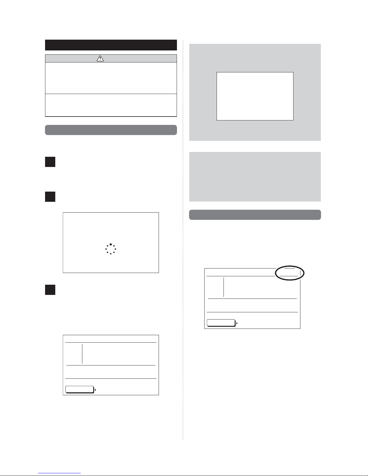
Select “Date/Time” with the [Cursor button], and press
1
the [Enter button].
“Date and Time” screen is displayed.
Submenu
Monitor:
Date/Time
R.C. prohibit
Setting:
Screen
Initial
Fr 10:00AM
9-3-1. Date setting
Select “Date” with the [Cursor button (Up/Down)] and
1
press the [Enter button].
Date and time
Date Fr, 01/01/2010
Time
Summer time
Daylight saving time
Change display format
Cancel: OK:
Initial Screen
Fr 10:00AM
10:00AM
Off
Select “Time” with the [Cursor button (Up/Down)] and
1
press the [Enter button].
Date and time
Fr 10:00AM
Date Fr, 01/01/2010
Time
Summer time
Daylight saving time
10:00AM
Off
Change display format
Cancel: OK:
Initial Screen
Time screen is displayed. Select the setting items (hour,
2
min. or AM/PM) with the [Cursor button (Left/Right)] and
set with the [Cursor button (Up/Down)].
(When setting the minutes, setting can be completed
quickly if the button is pressed continuously.)
Time
Fr 10:00AM
hour min
10: 00
Cancel: OK:
AM
Date Change display format
Date screen is displayed. Select the setting items (Day,
2
Month, or Year) with the [Cursor button (Left/Right)] and
set with the [Cursor button (Up/Down)].
Date
Fr 10:00AM
Day Month Year
01 / 01 / 2010
Friday
Cancel: OK:
Display format Time setting
When setting is completed, con rm it by pressing the
3
[Enter button]. When con rmed, the display returns to
the “Date and Time” screen.
If the [Cancel button] is pressed, the display returns to
4
the “Submenu” screen.
In addition, if the [Menu button] is pressed, the display
returns to the “Monitor” screen.
Notice
Display of date is the same style as the setting. Refer to
[9-3-4. Change display format setting].
When setting is completed, con rm it by pressing the
3
[Enter button].
When con rmed, the display returns to the “Date and
Time” screen.
If the [Cancel button] is pressed, the display returns to
4
the “Submenu” screen.
In addition, if the [Menu button] is pressed, the display
returns to the “Monitor” screen.
Notice
• Display of time is the same style as the setting.
Refer to [9-3-4. Change display format setting].
• Even when summer time (daylight saving time) is
applied, set the standard time here.
Set On/Off with [9-3-3. Summer time (Daylight
saving time) setting].
En-23
Page 25

9-3-3. Summer time (Daylight saving
time) setting
Notice
Set only for users in an area where summer time (daylight
saving time) is applicable.
Select “Summer time (daylight saving time)” with the
1
[Cursor button (Up/Down)] and press the [Enter button].
Date and time
Date Fr, 01/01/2010
Time
Summer time
Daylight saving time
Change display format
Cancel: OK:
Initial Screen
As the setting items (On or Off) are highlighted, set with
2
the [Cursor button (Up/Down)].
Fr 10:00AM
10:00AM
Off
9-3-4. Change display format setting
Select “Change display format” with the [Cursor button
1
(Up/Down)] and press the [Enter button].
Date and time
Date Fr, 01/01/2010
Time
Summer time
Daylight saving time
Change display format
Cancel: OK:
Initial Screen
“Change display format” screen is displayed. Select the
2
setting items (Date format or Time format) with the [Cursor button (Left/Right)] and set with the [Cursor button
(Up/Down)].
Change display format
Date format
Time format
00:00–11:59 AM/PMDay/Month/Year
Fr 10:00AM
10:00AM
Off
Fr 10:00AM
Date and time
Date Fr, 01/01/2010
Time
Summer time
Daylight saving time
Change display format
Cancel: OK:
Initial Screen
When setting is completed, con rm it by pressing the
3
[Enter button].
When con rmed, the display returns to the “Date and
Time” screen.
Fr 10:00AM
10:00AM
On
Note
When set to “On”, the time 1-hour in advance from the
standard time is displayed. When set to “Off”, the standard time is displayed.
When the [Cancel button] is pressed, the display re-
4
turns to the “Submenu” screen.
In addition, if the [Menu button] is pressed, the display
returns to the “Monitor” screen.
Cancel: OK:
Summer time/ D.S.T Date setting
Note
Available display formats are as follows:
Date format: Time format:
• Day/Month/Year • 00:00-23:59
• Month/Day/Year • 00:00-11:59 AM/PM
• Year/Month/Day • 12:00-11:59 AM/PM
When setting is completed, con rm it by pressing the
3
[Enter button].
When con rmed, the display returns to the “Date and
Time” screen.
When the [Cancel button] is pressed, the display re-
4
turns to the “Submenu” screen.
In addition, if the [Menu button] is pressed, the display
returns to the “Monitor” screen.
En-24
Page 26

11
9-4. Screen setting
9-4-2. Brightness setting
Select “Screen” with the [Cursor button] and press the
1
[Enter button].
“Screen” screen is displayed.
Submenu
Monitor:
Date/Time
R.C. prohibit
Setting:
Screen
Initial
Mo 10:00AM
9-4-1. Automatic off time setting
Setting of automatic turn off time for display screen backlight.
Select “Automatic off time” with the [Cursor button (Left/
1
Right)] and set with the [Cursor button (Up/Down)].
Screen
off time
60
s
Cancel: OK:
Date and time R.C. prohibition
Mo 10:00AM
ContrastBrightnessAutomatic
Select “Brightness” with the [Cursor button (Left/Right)],
1
and set with the [Cursor button (Up/Down)].
Screen
off time
60
Cancel: OK:
Date and time R.C. prohibition
Brightness
s
Mo 10:00AM
ContrastAutomatic
Note
The set is re ected while setting it.
Notice
When the automatic off time setting is set in “Off”,
Brightness setting is not displayed (It is not possible to
set it).
Other screen setting items can be set continuously. To
2
complete the setting, con rm it by pressing the [Enter
button].
When confirmed, display returns to the “Submenu”
screen.
In addition, if the [Menu button] is pressed, the display
returns to the “Monitor” screen.
9-4-3. Contrast setting
Note
The times which can set are as follows:
• 60s
• 30s
• Off (No illumination)
Automatic off time:
Notice
When the backlight is turned off by the automatic turn
off, the rst button operation is not effective, and illuminates the backlight.
If “Automatic off time” is set to “Off”, it is effective from
the rst button operation.
Other screen setting items can be set continuously. To
2
complete the setting, con rm it by pressing the [Enter
button].
When confirmed, display returns to the “Submenu”
screen.
In addition, if the [Menu button] is pressed, the display
returns to the “Monitor” screen.
En-25
Select “Contrast” with the [Cursor button (Left/Right)]
1
and set with the [Cursor button (Up/Down)].
Screen
off time
60
Cancel: OK:
Date and time R.C. prohibition
Brightness
s
Mo 10:00AM
ContrastAutomatic
Note
The set is re ected while setting it.
Other screen setting items can be set continuously. To
2
complete the setting, con rm it by pressing the [Enter
button].
When confirmed, display returns to the “Submenu”
screen.
In addition, if the [Menu button] is pressed, the display
returns to the “Monitor” screen.
Page 27

11
9-5. R.C. prohibition setting
Select “R.C. prohibit” with the [Cursor button] and press
1
the [Enter button].
“R.C. Prohibition” screen is displayed.
Submenu
Date/Time
Screen
Mo 10:00AM
Reversed display is released when the [Enter button] is
4
pressed.
(If set to “All units”, the same setting is displayed in
each indoor unit).
When setting other indoor units, repeat the same pro-
cedure.
When [Cancel button] is pressed, the display returns to
5
the “Submenu” screen.
In addition, if the [Menu button] is pressed, the display
returns to the “Monitor” screen.
R.C. prohibit
Monitor:
Select indoor unit (Room X) or “All units” with the [Cursor
2
button (Up/Down)] and press the [Enter button].
When indoor units cannot be displayed in a screen, ope-
rate by referring to the gauge at the right edge.
Setting:
Initial
Gauge
Mo 10:00AM
Mo 10:00AM
R.C. prohibition
R.C. prohibition
R.C. prohibition
All units
All units
All units
Room 1
Room 1
Room 1
Room 2
Room 2
Room 2
Room 3
Room 3
Room 3
Room 4
Room 4
Room 4
Cancel: OK:
Cancel: OK:
Cancel: OK:
Screen Initial
Screen Initial
Screen Initial
As the setting item is highlighted, set “Permit” or “Pro-
3
hibit” with the [Cursor button (Up/Down)] and press the
[Enter button].
Mo 10:00AM
Permit
Permit
Permit
Permit
Permit
Permit
Permit
Permit
Permit
Permit
Permit
Permit
R.C. prohibition
All units Prohibit
Room 1
Room 2
Room 3
Room 4
Cancel: OK:
Screen Initial
Mo 10:00AM
Permit
Permit
Permit
Permit
En-26
Page 28

11
9-6. Initial setting
9-6-2. Temperature unit setting
Select “Initial” with the [Cursor button], and press the
1
[Enter button].
“Initial” screen is displayed.
Submenu
Monitor:
Date/Time
R.C. prohibit
Setting:
Screen
Initial
Mo 10:00AM
9-6-1. Language setting
Select “Language” with the [Cursor button (Up/Down)]
1
and press the [Enter button].
Initial
Language
Temp. unit
Mo 10:00AM
English
°C
Select “Temp. unit” with the [Cursor button (Up/Down)]
1
and press the [Enter button].
Mo 10:00AM
Initial setting
Initial setting
Language
Language
Temp. unit
Temp. unit
Back:
Back:
R.C. prohibition Date and time
R.C. prohibition Date and time
Set “°C” and “°F” with the [Cursor button (Up/Down)]
2
and press the [Enter button].
The display returns to the “Initial” screen.
Setting:
Setting:
Temp. unit setting
Mo 10:00AM
English
English
°C
°C
Mo 10:00AM
Temp. unit
°F
Cancel: OK:
Language
Back:
Setting:
R.C. prohibition Date and time
The display language of this product is only English.
2
Press the [Enter button] to return to the “Initial” screen.
Language
Mo 10:00AM
English
Cancel: OK:
Temp. unit
When the [Cancel button] is pressed, the display re-
3
turns to the “Submenu” screen.
If the [Cancel button] is pressed, the display returns to
3
the “Submenu” screen.
En-27
Page 29

10. OTHERS
1
1
10-1. Troubleshooting
If the problem persists after performing these checks, or if you
notice burning smells, stop operation immediately, turn off the
electrical breaker, and consult with authorized service personnel.
WARNING
• In the event of a malfunction (burning smell, etc.),
immediately stop operation, turn off the electrical breaker
and consult authorized service personnel.
• Merely turning off the unit’s power switch will not
completely disconnect the unit from the power source.
Always be sure to turn off the electrical breaker to ensure
that power is completely off.
Before requesting service, perform the following checks:
See
Page
CHECK
ONCE
MORE
Symptom
Doesn’t
operate
at all:
Items to check
• Has the circuit breaker been
turned off?
• Has there been a power
failure?
• Has a fuse blown out, or a
circuit breaker been tripped?
• Is the timer operating?
• Is key lock enabled? 8
Power
indicator
is blinking:
• Has the circuit breaker been
turned off?
• Has a fuse blown out, or a
circuit breaker been tripped?
Notice
For an error displayed on the indoor unit or the standard
remote controller, refer to the operating manual and the
installation manual for the indoor unit.
10-2. Error code
This appears automatically on the display if an error occurs.
If an error occurs, the following display will be shown.
If “Error code: XX” is displayed, immediately contact authorized
service personnel.
Stop air conditioner operation and please consult authorized
service personnel.
4
Error code Contents
12 Remote controller communication error
Error
code: XX
NORMAL
FUNCTION
Air ow is
stopped:
Power indicator
• During Heating operation,
the unit will temporarily stop
operation (between 4 and 15
minutes) as the Automatic
Defrosting mode operates.
• During Heating operation,
the unit will temporarily stop
operation (Max. 5 minutes)
as the Automatic Oil
Recovery mode operations.
•
When operated in a incorrect
combination of operation
mode, the indoor unit
stops directly and display
of corresponding indoor
units is blinking on the
“Monitor”screen of the central
remote controller.
9
En-28
 Loading...