

Page 1
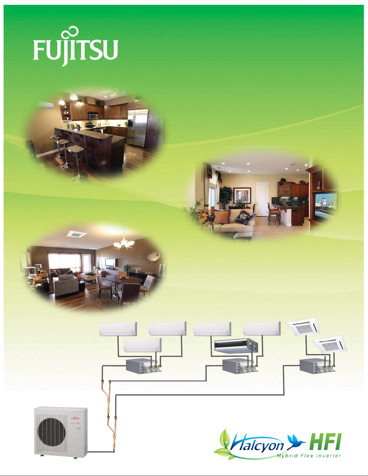
Hybrid Flex Inverter System
48,000 BTU 8-Zone Mix & Match Flexibility
For over 35 years, Fujitsu has been
making the hottest places cool and
the coolest places more comfortable.
Mini-Split Air Conditioners
and Heat Pumps
Wall Mounted
Slim Duct
Compact Cassette
Page 2
Multi-Zone Limitations
• Shorter piping length
• Fewer number of zones
• No central remote control
• No over connectable
capacity
HFI
• 130% capacity
• Up to 8 zones
• Central remote
• Lower copper
tubing costs
• Miswiring
detection
HFI
• Long piping
• Better value
• SEER rated
• Flare connections
• Easier installation
• 4-way outdoor
unit connection
BENEFITS
What is a Hybrid?
The blending of a complex VRF system with the simplicity of a
multi-zone system to create a new hybrid solution that shares
the best of both systems.
Why Flex?
The ability to create the right combinations, the right quantity
(up to 8-zones), the right style indoor units, and the right
capacity. It’s the right choice for your home or business.
Why Inverter?
An Inverter is a system that controls the rotational speed (not
just an ON/OFF signal) of an electric motor by adjusting the
frequency and voltage of the electrical power supplied to the
motor. The inverter constantly regulates the compressor speed
to its optimum energy usage, producing higher refrigerant
performance with less power consumption.
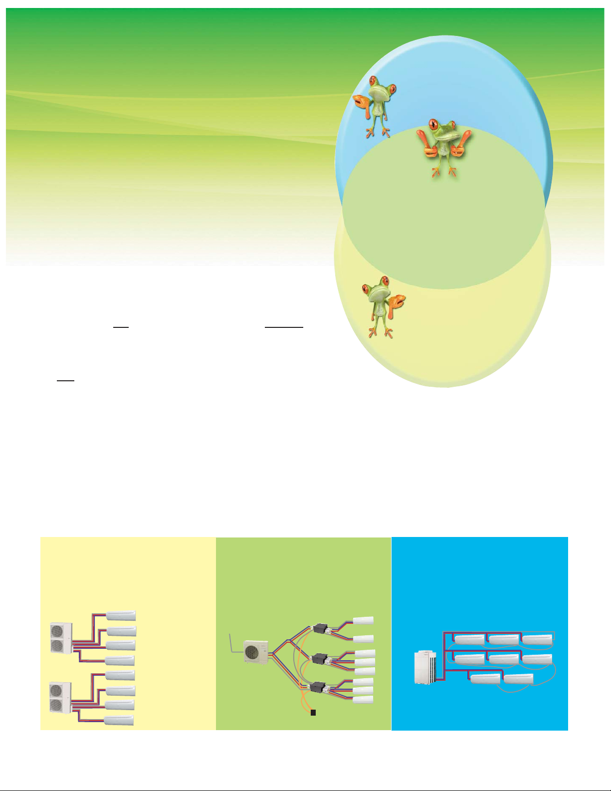
TYPICAL INVERTER VRF SYSTEM
• Variable speed compressor
• Computerized zone control
• Expansion valves are mounted either
within or near the indoor unit, and
engineered piping maximizes
compressor efficiency to create an
optimized refrigerant path.
AHRI defines VRF as having three main features: (1) a variable speed compressor, (2) a computerized control
individual zoning system and (3) optimized refrigerant path of installation.
HFI vs. Multi vs. VRF
TYPICAL INVERTER MULTI-ZONE
• Variable speed compressor
• Computerized zone control
• With the expansion valves mounted
in the outdoor unit, it does not have
an optimized refrigerant path.
Halcyon Hybrid Flex Inverter
• Variable speed compressor
• Computerized zone control
• Remotes expansion valves from the
outdoor unit to mid-stream in the
refrigerant piping, creating a semioptimized refrigerant path.
• 2 outdoor
units needed
• No separation
tube assemblies needed
• All flare
• 2 separation
assemblies
needed
• All sweat connections
• 7 separation assemblies needed
VRF Limitations
• Expensive
• Sweat connections
• Computer design required
• No efficiency label today
• Increased labor to install
Power
Power
2
130% Connectable Capacity (AOU48RLXFZ1 Only)
The HFI system is rated at 48,000 BTUs but you can connect
up to 130%, or 62,000 BTUs of rated indoor unit capacity to the
AOU48RLXFZ1. Connectable capacity allows you to connect
indoor units that can exceed outdoor unit capacity. However, if
you connect indoor units that exceed 100% of the outdoor unit’s
capacity there are limitations.
If all indoor units are cooling or heating at the same time, the system
will limit
their capacity so that their total matches the outdoor unit’s capacity.
When a zone meets a desired set temperature it requires less capacity. The
unused capacity is then distributed to the remaining indoor units, increasing their capacity.
For Example: The load on a small 2-story office building with a business downstairs and worker apartments
upstairs is 62,000 BTUs (38,000 BTUs downstairs and 24,000 BTUs upstairs) but the workers aren’t upstairs
and downstairs at the same time, therefore not all units will be running simultaneously allowing 100% heating
or cooling to occupied spaces.
Page 3
Back
Right
Front
Bottom
3
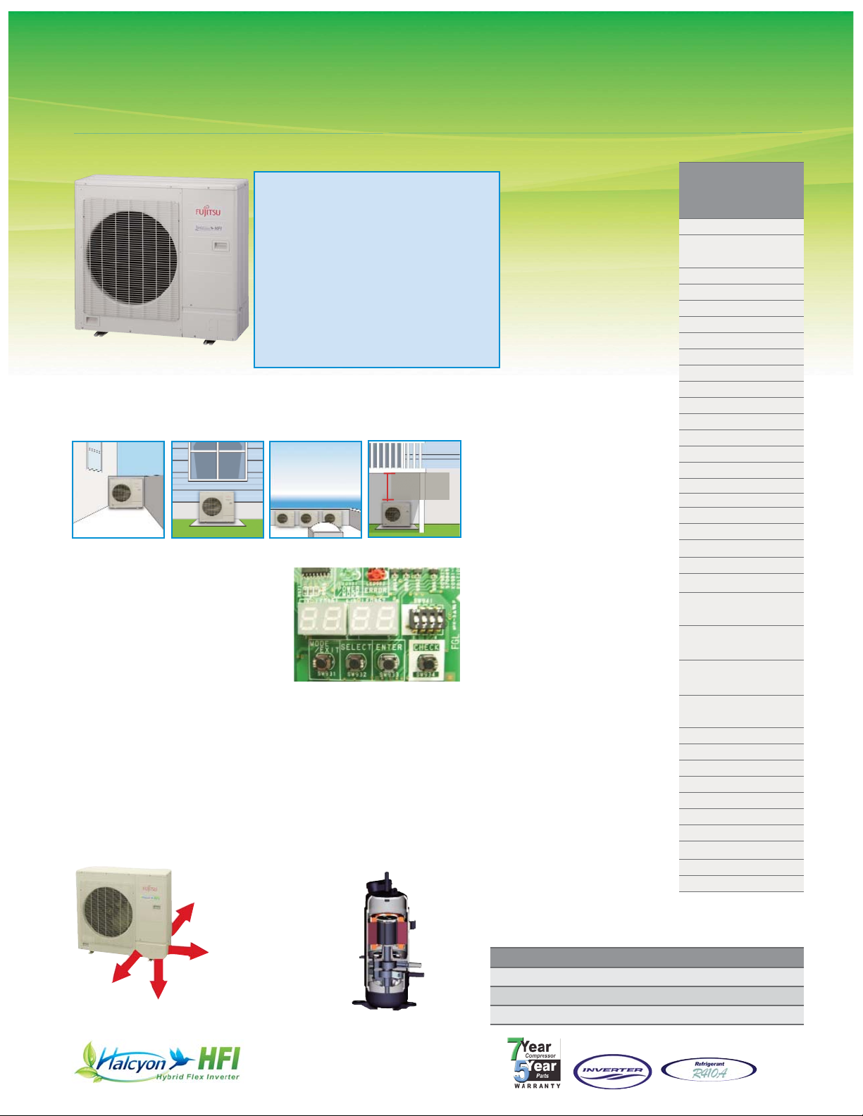
Outdoor Unit 48,000 BTUs
AOU48RLXFZ1
Connectable Indoor Unit Number
Connectable Indoor Unit Capacity
Connectable Branch Box Number
Nominal Cooling BTU/h
Max Cooling BTU/h
Nominal Heating BTU/h
Low Temp. Heating 17°F BTU/h
Max Heating BTU/h
Clg. Operating Range °F(°C)
Htg. Operating Range °F(°C)
Input Power: Cooling Rated kW*
Input Power: Heating Rated kW*
Voltage/Frequency/Phase
Current: Clg Outdoor Max.
(A)
Current: Htg Outdoor Max. (A)
Recommended Fuse Size (A)
Outdoor Fan Speed RPM (Clg/Htg)
Fan: Type x Quantity
Fan Motor Output W
Sound Pressure Level Cooling
dB(A)
Sound Pressure Level Heating dB(A)
Max. Pipe Length Total Ft (m)
Max. Pipe Length Between Box &
Farthest Indoor Unit Ft (m)
Max. Pipe Height Difference Between
Outdoor Unit & Branch Box Ft (m)
Max. Pipe Height Difference
Between Indoor Units Ft (m)
Max. Pipe Height Difference Between
Outdoor Unit & Farthest Indoor Ft (m)
Connection Method
Conn. Pipe Diameter
Inch
Net Weight lbs. (kg)
Dimensions: Height Inch
mm
Width Inch
mm
Depth Inch
mm
Refrigerant
AOU48RLXFZ1
Heat Pump
2 to 8
80 to 130% Nominal
(39,000 - 62,000 BTU)
1 to 3
48,000
51,100
54,000
40,000
57,000
23-115 (-5-46)
5-75 (-15-24)
5.52 / 5.19 / 5.35
5.02 / 4.89 / 4.96
208-230/60/1
24.5 / 23.0 / 23.7
22.3 / 21.7 / 22.0
40
890/910
Propeller x 1
111
56
58
377 (115)
49 (15)
98 (30)
98 (30)
98 (30)
Flare
3/8 (Liq.) 5/8 (Suc.)
216 (98)
36
914
38-1/4
970
14-5/8
370
R410A
Compact Size
The compact size of outdoor unit AOU48RLXFZ1 allows for
many installation opportunities.
Self Diagnostic Feature
This printed circuit board provides
three modes of diagnostics setting, monitoring and function
mode, as well as error codes.
It also provides a precommissioning check function.
Setting mode allows optional
functions to be selected. Monitoring mode provides temperature
for each thermistor, compressor operation and other functions.
Function mode provides cooling test run, heating test run and
pump down operation.
Piping Flexibility
Contractors can choose the
best direction for piping from
the outdoor unit.
DC Twin Rotary Compressor
A high performance, low
noise, large capacity DC twin
rotary compressor is used.
Includes Quiet Mode for night
operation.
l
Connect 2 to 8 indoor units
l 80 to 130% connectable capacity
l
Connect 39,000 to 62,000 BTU
SEER HSPF EER**
Ducted 14.7 9.3 8.7
Non-Ducted 17.0 9.8 9.25
Mixed 15.8 9.5 8.97
2 Indoor Units
18k BTU/h + 24 k BTU/h = 42k BTU/h ··OK
12k BTU/h + 24 k BTU/h = 36k BTU/h ··Not
Allowed (below 80%)
8 Indoor Units
7k BTU/h × 8 units = 56k BTU ··OK
9k BTU/h × 8 units = 72k BTU ··Not Allowed
(over 130%)
**Cooling
*Ducted / Non-Ducted / Mixed
40” minimum
clearance
required
Page 4
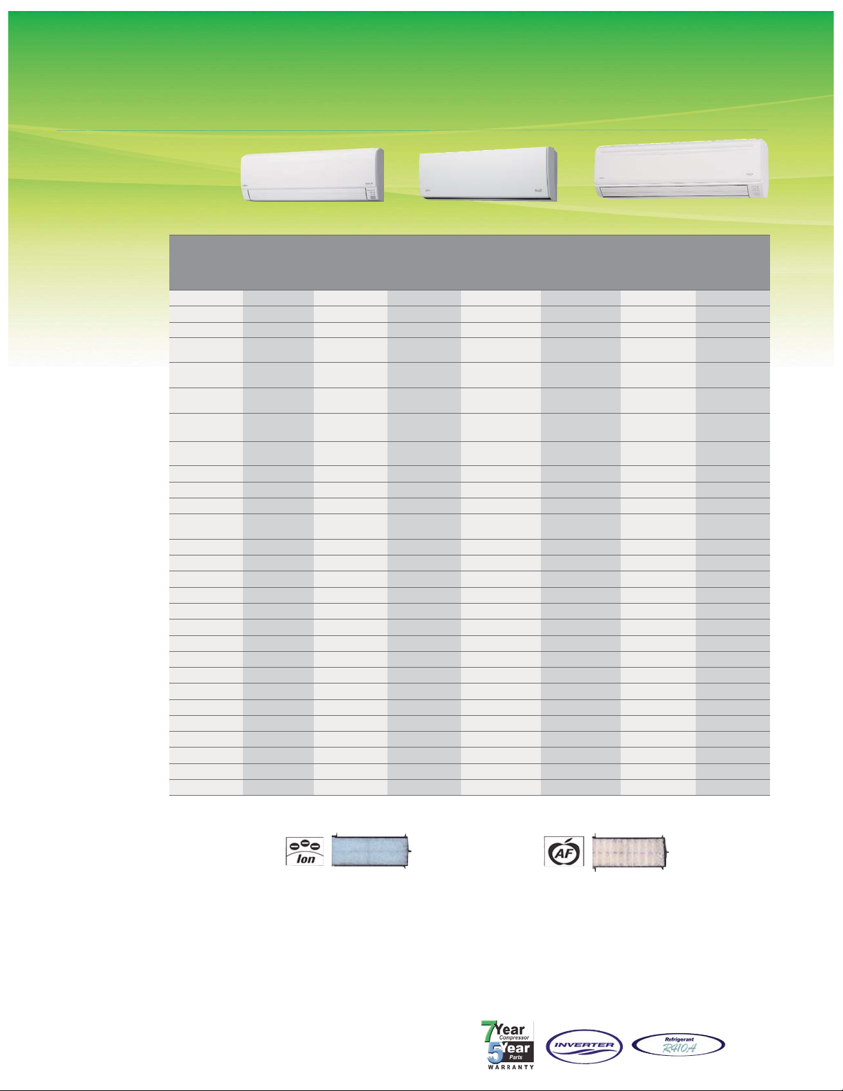
Wall Mounted 7, 9, 12, 18 and 24,000 BTUs
ASU7RLF, ASU9RLF, ASU12RLF, ASU18RLF, ASU24RLF
4
ASU7, 9, 12RLF ASU18, 24RLF
Long-life
+
Ion Deodorization Filter
The filter deodorizes by powerfully
decomposing absorbed odors using
the oxidizing and reducing effects of
ions generated by the ultra-fineparticle ceramic.
+ The filter can be used for approximately 3 years if it is washed with water when dirty to restore it's surface action.
Built In FiltrationStandard Features
l
Wireless Remote Control*
l
Apple Catechin Filter
l
Ion Deodorizing Filter
l Sleep Timer
l 24-Hour Timer
l Dry Mode
l Auto Louver: 4-Way**
l Auto Mode
l Minimum Heat Mode
l Auto Restart/Reset
l Power Diffuser**
* Features vary by model and therefore standard wireless remote
controls should be used with the models they are associated with.
**Feature of models ASU18, 24RLF only.
Nominal Cooling BTU/h*
Nominal Heating BTU/h*
Voltage/Frequency/Phase
Air Circ.
C.F.M. (m3/h): Hi
Medium
Low
Quiet
Noise Level
dB(A) (Clg/Htg): Hi
Medium
Low
Quiet
Running Current
Rated (A): Cooling
Heating
Power Use
Rated (w): Clg
Htg
Fan Speeds Stage
Air Direction: Horizontal
Vertical
Primary Air Filter
Ion Deodorizing Filter
Apple-Catechin Filter
Connection Method
Conn. Pipe Diameter
Inch
Net Weight lbs. (kg)
Dims: Height Inch (mm)
Width Inch (mm)
Depth Inch (mm)
Refrigerant
ASU7RLF
Heat Pump
ASU9RLF
Heat Pump
ASU9RLS2
Heat Pump^
ASU12RLF
Heat Pump
ASU12RLS2
Heat Pump^
ASU15RLS2
Heat Pump^
ASU18RLF
Heat Pump
ASU24RLF
Heat Pump
7,000 9,000 9,000 12,000 12,000 14,500 18,000 24,000
8,100 10,200 12,000 13,500 16,000 18,000 20,000 27,000
208-230/60/1 208-230/60/1 208-230/60/1 208-230/60/1 208-230/60/1 208-230/60/1 208-230/60/1 208-230/60/1
Clg 330 (560)
Htg 330 (560)
Clg 353 (600)
Htg 353 (600)
Clg 500 (850)
Htg 500 (850)
Clg 388 (660)
Htg 388 (660)
Clg 500 (850)
Htg 500 (850)
Clg 530 (900)
Htg 530 (900)
Clg 542 (920)
Htg 542 (920)
Clg 659 (1,120)
Htg 647 (1,100)
Clg 294 (500)
Htg 294 (500)
Clg 306 (520)
Htg 306 (520)
Clg 394 (670)
Htg 394 (670)
Clg 330 (560)
Htg 330 (560)
Clg 394 (670)
Htg 394 (670)
Clg 436 (740)
Htg 436 (740)
Clg 436 (740)
Htg 436 (740)
Clg 530 (900)
Htg 530 (900)
Clg 253 (430)
Htg 253 (430)
Clg 253 (430)
Htg 253 (430)
Clg 324 (550)
Htg 324 (550)
Clg 265 (450)
Htg 277 (470)
Clg 324 (550)
Htg 324 (550)
Clg 336 (570)
Htg 336 (570)
Clg 365 (620)
Htg 365 (620)
Clg 436 (740)
Htg 436 (740)
Clg 200 (340)
Htg 206 (350)
Clg 200 (340)
Htg 206 (350)
Clg 174 (300)
Htg 174 (300)
Clg 200 (340)
Htg 206 (350)
Clg 194 (330)
Htg 194 (330)
Clg 229 (390)
Htg 229 (390)
Clg 324 (550)
Htg 324 (550)
Clg 365 (620)
Htg 365 (620)
36/36 37/37 43/43 40/40 43/43 45/45 43/44 49/48
32/32 33/33 37/38 36/36 37/38 40/40 37/37 42/42
29/29 29/29 32/32 30/31 32/32 33/34 33/33 37/37
25/25 25/25 21/21 25/25 21/21 25/27 31/31 33/33
0.13 0.15 0.14 0.19 0.17 0.20 0.32 0.53
0.13 0.15 0.14 0.19 0.17 0.20 0.32 0.53
15 17 56 22 87 121 41 69
15 17 80 22 120 135 41 69
4+auto 4+auto 4+auto 4+auto 4+auto 4+auto 4+auto 4+auto
Manual Manual Manual Manual Manual Manual Auto Auto
Auto Auto Auto Auto Auto Auto Auto Auto
Washable Washable Washable Washable Washable Washable Washable Washable
Disposable Disposable Disposable Disposable Disposable Disposable Disposable Disposable
Disposable Disposable Disposable Disposable Disposable Disposable Disposable Disposable
Flare Flare Flare Flare Flare Flare Flare Flare
suc 3/8 dis 1/4 suc 3/8 dis 1/4 suc 3/8 dis 1/4 suc 3/8 dis 1/4 suc 3/8 dis 1/4 suc 1/2 dis 1/4 suc 1/2 dis 1/4 suc 5/8 dis 1/4
18 (8) 18 (8) 21 (9.5) 18 (8) 21 (9.5) 21 (9.5) 31 (14) 31 (14)
11-1/16 (280) 11-1/16 (280)
11-1/8 (282)
13-1/4* (337*)
11-1/16 (280)
11-1/8 (282)
13-1/4* (337*)
11-1/8 (282)
13-1/4* (337*)
12-5/8 (320) 12-5/8 (320)
31-1/16 (790) 31-1/16 (790) 34-1/4 (870) 31-1/16 (790) 34-1/4 (870) 34-1/4 (870) 39-1/4 (998) 39-1/4 (998)
8 (203) 8 (203) 7-1/4 (185) 8 (203) 7-1/4 (185) 7-1/4 (185) 9 (228) 9 (228)
R410A R410A R410A R410A R410A R410A R410A R410A
Apple-Catechin Filter
Dust, mold spores and microorganisms are absorbed onto the
filter by static electricity and growth
is inhibited and deactivated.
ASU9, 12, 15RLS2
^
^Compatible only with outdoor unit AOU48RLXFZ1. *Height when front panel is open.
Page 5

5
Compact Cassettes 9, 12, and 18,000 BTUs
AUU9RLF, AUU12RLF, AUU18RLF
AUU9RLF
Heat Pump
AUU12RLF
Heat Pump
AUU18RLF
Heat Pump
9,000 12,000 18,000
10,200 13,500 20,000
208-230/60/1 208-230/60/1 208-230/60/1
318 (540)
Clg or Htg
359 (610)
Clg or Htg
441 (750) Clg
471 (800) Htg
288 (490)
Clg or Htg
312 (530)
Clg or Htg
359 (610) Clg
418 (710) Htg
259 (440)
Clg or Htg
277 (470)
Clg or Htg
306 (520) Clg
353 (600) Htg
230 (390)
Clg or Htg
241 (410)
Clg or Htg
241 (410) Clg
265 (450) Htg
33/34 37/37 42/44
31/32 33/33 37/40
29/29 31/31 33/37
27/27 28/28 29/30
0.15 0.19 0.30
0.15 0.19 0.30
18 23 39
18 23 39
4+auto 4+auto 4+auto
Automatic Automatic Automatic
Washable Washable Washable
UTG-CCGF* UTG-CCGF* UTG-CCGF*
Flare Flare Flare
suc 3/8 dis 1/4 suc 3/8 dis 1/4 suc 1/2 dis 1/4
33 (15) 33 (15) 33 (15)
9-11/16 (245) 9-11/16 (245) 9-11/16 (245)
22-7/16 (570) 22-7/16 (570) 22-7/16 (570)
22-7/16 (570) 22-7/16 (570) 22-7/16 (570)
1-15/16 (49) 1-15/16 (49) 1-15/16 (49)
27-9/16 (700) 27-9/16 (700) 27-9/16 (700)
27-9/16 (700) 27-9/16 (700) 27-9/16 (700)
R410A R410A R410A
22.5”
22.5”
Easy Installation
Fits into a standard ceiling tile*.
Compact cassette and slim duct models
can be networked.
*Dimensions of outer grille are 27-9/16” x 27-9/16”
and may overlap adjacent tiles.
Nominal Cooling
BTU/h
Nominal Heating BTU/h
Voltage/Frequency/Phase
Air Circ.
C.F.M. (m3/h): Hi
Medium
Low
Quiet
Noise Level
dB(A) Clg/Htg: Hi
Medium
Low
Quiet
Running Current
Rated (A): Cooling
Heating
Power Use
Rated/Max (W): Clg
Heating
Fan Speeds Stage
Air Direction: Vertical
Air Filter
Front Grille
Connection Method
Conn. Pipe Diameter
Inch
Net Weight lbs. (kg)
Chassis Dim: Height Inch (mm)
Width Inch (mm)
Depth Inch (mm)
Grille Dim: Height Inch (mm)
Width Inch (mm)
Depth Inch (mm)
Refrigerant
Fresh Air Kit**
UTZ-VXAA
Mixes room air then passes
through the heat exchanger.
2-Stage Turbo Fan
Air distribution is evenly spread across
the heat exchanger by the new 2 stage
turbo fan which produces two separate
airflow streams.
Heat exchange
efficiency:
Increased 20%
1-stage
2-stage
Standard Features
l
Sleep Timer
l
Dry Mode
l
Auto Louver: Up/ Down
l Quiet Mode
l Auto Restart/Reset
l Remote Temperature Sensor
l High Ceiling Mode
l Condensate Pump
l 2-Stage Turbo Fan
l Minimum Heat Mode+
l
Fresh Air Intake**
+ Available only with optional wireless remote control.
**Requires Fujitsu’s Optional Fresh Air Kit part #UTZ-VXAA. Allows for a 4-inch flex duct connection.
Requires a field supplied duct booster fan capable of 60 CFM at .2”W.C. or 90 CFM at .4”W.C.
For fan static pressure requirements, see installation manual. Add hood, filter and duct losses for
fan total static pressure requirements. Will add 4” to the height of the indoor unit.
* Compact Cassette Grille UTG-CCGF sold separately. Must order one with each compact cassette.
Page 6
6
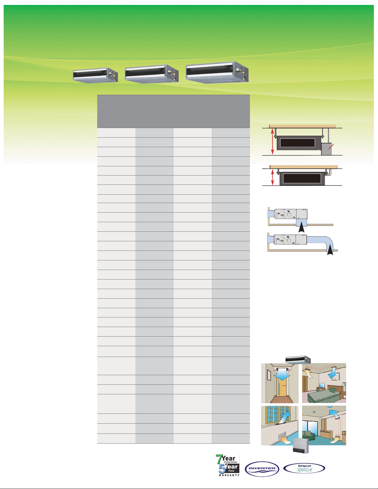
Slim Duct 9, 12, 18 and 24,000 BTUs
ARU9RLF, ARU12RLF, ARU18RLF, ARU24RLF
Nominal Cooling BTU/h
Nominal Heating BTU/h
Voltage/Frequency/Phase
Static Pressure
In. W. C.
Air Circ. C.F.M. (m
3
/h) Clg/Htg: Hi
Medium
Low
Quiet
Noise Level
dB(A) (Clg/Htg): Hi
Medium
Low
Quiet
Running Current
Rated (A): Cooling
Heating
Power Use
Rated (W): Cooling
Heating
Fan Speeds Stage
Air Filter
Connection Method
Conn. Pipe Diameter
Inch
Net Weight lbs. (kg)
Dimensions: Height Inch (mm)
Width Inch (mm)
Depth Inch (mm)
Supply Duct Flange
Dimensions: Height Inch (mm)
Width Inch (mm)
Depth Inch (mm)
Return Duct Flange
Dimensions: Height
Inch (mm)
Width Inch (mm)
Depth Inch (mm)
Refrigerant
ARU9RLF
Heat Pump
ARU12RLF
Heat Pump
ARU18RLF
Heat Pump
ARU24RLF
Heat Pump
9,000 12,000 18,000 24,000
10,200 13,500 20,000 27,000
208-230/60/1 208-230/60/1 208-230/60/1 208-230/60/1
0 ~ 0.36 0 ~ 0.36 0 ~ 0.36 0 ~ 0.20
353 (600) 383 (650) 554 (940) 783 (1,330)
324 (550) 353 (600) 518 (880) 730 (1,240)
294 (500) 324 (550) 483 (820) 648 (1,100)
265 (450) 283 (480) 442 (750) 607 (1,030)
28/28 29/29 32/33 33/35
27/26 28/28 31/32 32/34
26/25 27/27 30/31 30/32
25/24 26/24 29/29 29/29
0.30 0.35 0.44 0.66
0.30 0.35 0.44 0.66
49 58 73 111
49 58 73 111
4 + Auto 4 + Auto 4 + Auto 4 + Auto
Washable Washable Washable Washable
Flare Flare Flare Flare
suc 3/8 dis 1/4 suc 3/8 dis 1/4 suc 1/2 dis 1/4 suc 5/8 dis 1/4
41 (19) 41 (19) 50 (23) 59 (27)
7-25/32 (198) 7-25/32 (198) 7-25/32 (198) 7-25/32 (198)
27-9/16 (700) 27-9/16 (700) 35-7/16 (900) 43-5/16 (1,100)
24-13/32 (620) 24-13/32 (620) 24-13/32 (620) 24-13/32 (620)
5-15/16 (151) 5-15/16 (151) 5-15/16 (151) 5-15/16 (151)
25-19/32 (650) 25-19/32 (650) 33-15/32 (850) 41-11/32 (1,050)
3/4 (19) 3/4 (19) 3/4 (19) 3/4 (19)
6-27/32 (174) 6-27/32 (174) 6-27/32 (174) 6-27/32 (174)
22-19/32 (574) 22-19/32 (574) 30-15/32 (774) 38-11/32 (974)
3/4 (19) (Flat) 3/4 (19) (Flat) 3/4 (19) (Flat) 3/4 (19) (Flat)
R410A R410A R410A R410A
Return Air-intake Choices
Back
Standard Features
l Wired Remote Control
l
Dry Mode
l Weekly Timer
l Auto Mode
l Quiet Mode
l
Auto Restart/Reset
l
Condensate Pump
l
Fresh Air Intake
Slim Duct
Built-in drain pump allows for
installation of slim duct unit in
smaller spaces than traditional
units.
Drain
Pump
13”
9.4”
Traditional
Slim Duct
Bottom
Flexible Installation
Horizontal or vertical.
ARU9, 12RLF ARU18RLF ARU24RLF
Page 7

7
Branch Boxes
UTP-PU03A, UTP-PU03B
Connectable Indoor Unit
Max. Combination
BTU/h
Min. Combination BTU/h
Clg. Operating Range °F(°C)
Htg. Operating Range °F(°C)
%RH
Voltage/Frequency/Phase
Maximum Current Ampacity
(A)
Running Current Rated (A): Cooling
Heating
Power Use
Rated (W): Cooling
Heating
UTP-PU03A
Primary
UTP-PU03B
Secondary
1 ~ 3 1 ~ 3
62,000 Nom.* 62,000 Nom.*
7,000 Nom.* 7,000 Nom.*
25-115 (-5-46) 25-115 (-5-46)
5-75 (-15-24) 5-75 (-15-24)
80 or less 80 or less
208-230/60/1 208-230/60/1
15 15
0.050 0.050
0.050 0.050
10 10
10 10
UTP-PU03B
Clearances
Dimensions: Gross (Flare to Flare):
Height x Width x Depth Inch
Height x Width x Depth mm
Dimensions: Net (Metal Box Only):
Height x Width x Depth Inch
Height x Width x Depth mm
Net Weight lbs. (kg)
Conn. Pipe Diameter - Main Inch
Conn. Pipe Diameter - Branch Inch
Connection Method
Connection Adapter Included
Inch
UTP-PU03A
Primary
UTP-PU03B
Secondary
7-5/8 x 33 x 14-5/8 7-5/8 x 33 x 14-5/8
195 x 838 x 370 195 x 838 x 370
7-5/8 x 17 x 14-5/8 7-5/8 x 17 x 14-5/8
195 x 433 x 370 195 x 433 x 370
20 (9) 20 (9)
(3/8 Liq. x 5/8 Suc.) (3/8 Liq. x 5/8 Suc.)
(1/4 Liq. x 1/2 Suc.)
3 pair
(1/4 Liq. x 1/2 Suc.)
3 pair
Flare Flare
(1/2MF x 3/8FF) x 3
(1/2MF x 5/8FF) x 3
No adapter needed
for 18k BTU
(1/2MF x 3/8FF) x 3
(1/2MF x 5/8FF) x 3
No adapter needed
for 18k BTU
15-3/4 in.
or more
23-5/8 in. or more
Access
Panel
Service Space
33-1/2 in. or more
15-3/4 in.
or more
23-5/8 in. or more
11-7/8 in.
or more
27-1/2 in. or more
Access
Panel
Access
Direction
Service Space
33-1/2 in. or more
11-7/8 in.
or more
27-1/2 in. or more
Access Panel Dims
23-5/8 x 33-1/2 in.
or as needed.
Side Access Panel, Vertical Box Mount
Access Panel Dims
27-1/2 x 33-1/2 in.
or as needed.
Top Access Panel, Vertical Box Mount
*As long as the total system nominal capacity is between 39,000 and 62,000 BTUs.
Btm. Access Panel, Horiz. Box Mount
Threaded Rod Mount
Bottom View
Dimensions In (mm)
Unit A
Unit B
Unit C
(85)
(42)
7-5/8 (195)
3-11/32
1-5/8
3-3/4
(95)
3-3/4
(95)
13 (304)
2-1/4 (57)
1-5/8
(66)
28 in. or more
12 in. or more
34 in. or more
Access
Panel
Dims
28 x 34 in.
or as
needed.
Hanger Bolt
18-15/32 (469)
17 (433)
1-3/4
(44)
1-9/16
(40)
1-9/16
(40)
9-7/8 (251)
6-1/16
(154)
13 (304)
10-3/32 (256)
Hanger Bolt
15/16
(24)
2-15/16
(75)
3-3/4
(95)
4-3/4 (120)
1 (25)5-13/16 (148)
Warning: Branch boxes are not weather tight enclosures and cannot be mounted outdoors or in damp environments exceeding
80% relative humidity, unless using the Branch Box Outdoor Enclosure, Part #UTP-PX-A. See Page 8 for more information.
UTP-PU03A
Page 8

8
Allowable Combinations
Separation Tube Assembly Kit
UTP-SX248A
Size
Liquid Inch 3/8 x 3/8 x 3/8
Suction Inch 5/8 x 5/8 x 5/8
Allowed Branch Box Mounting Direction
Threaded Rod Mount Horizontal Wall Mount Vertical Wall Mount
By reversing the electri-
cal box position you can
orient the inlet and outlet
pipes into a left hand or
right hand configuration.
By reversing the electrical
box position you can
orient the inlet and outlet
pipes into a left hand or
right hand configuration.
You cannot reverse the
electrical box position
when mounting the
branch box vertically.
Branch Boxes (continued)
UTP-PU03A, UTP-PU03B
AOU48RLXFZ1 offers over 250 combinations of systems based on BTU/h. When both indoor type and BTU/h are considered,
there are over 9,000 combinations of systems! For a full listing of combinations, please visit:
www.fujitsugeneral.com/combinations.pdf.
The Branch Box
Enclosure, used to
mount the indoor style
Branch Box outdoors, is
a painted metal cover to
match the condensing
unit. When Branch Box
Outdoor Enclosure is not
required, see Installation
Manual for indoor
mounting instructions.
Branch Box Outdoor Enclosure
Model UTP-PX-A
Wall
Mounted
Ground
mounted on
snow risers
Allowed Mounting
Positions
Eave
Mounted
Accessory Compatibility
9RLS2
12RLS2
15RLS2
RLF: Small Wall
(7, 9, 12k BTU)
RLF: Large Wall
(18,, 24k BTU)
AUU: Cassette
ARU: Slim Duct
AOU48RLXFZ1
UTY-XWZX Dry Contact Wire Kit
l^
l l
UTY-XWZXZ5 Dry Contact Wire Kit
l+l+l
+
UTD-ECS5A Slim Duct Connector Kit
l
K9R410A55 R410A Swivel Adapter
l l l l l l l
UTY-DMMUM Central Remote Control
l
UTY-RNNUM Wired Remote Control
l+l+l+l^
l
UTY-RSNUM Simple Remote Control
l+l+l+l^
l l l
UTY-LRHUM Receiver Unit
l
UTY-LNHUM Wireless Remote Control
l
^ Wall mounted ASU7, 9, and 12RLF require accessory interface kit #UTY-XCBXZ1 in order to connect these devices to them.
+ Wall mounted ASU9, 12, and 15RLS2 require accessory interface kit #UTY-TWBXF in order to connect these devices to them.
9RLS2
12RLS2
15RLS2
RLF: Small Wall
(7, 9, 12k BTU)
RLF: Large Wall
(18,, 24k BTU)
AUU: Cassette
ARU: Slim Duct
AOU48RLXFZ1
UTY-XCBXZ1 Interface Kit^
l
UTY-TWBXF
Interface Kit
+
l l l
UTR-YDZB Air Outlet Shutter Plate
l
UTY-XSZX Remote Sensor
l
UTZ-VXAA Fresh Air Intake Kit
l
K3PST
3-Pole Single Throw
Safety Switch
l l l l l l l
UTZ-KXGC High Humidity Insulation Kit
l
UTY-XWZXZ3
Outdoor Unit Input/Output Connector
l
UTY-XWZXZ4
Outdoor Unit Base Heater Connector
l
360° rotation on its vertical axis
+/- 10° of 90° vertical
+/- 10° of 0°
horizontal
360° rotation on its vertical axis
Page 9
9
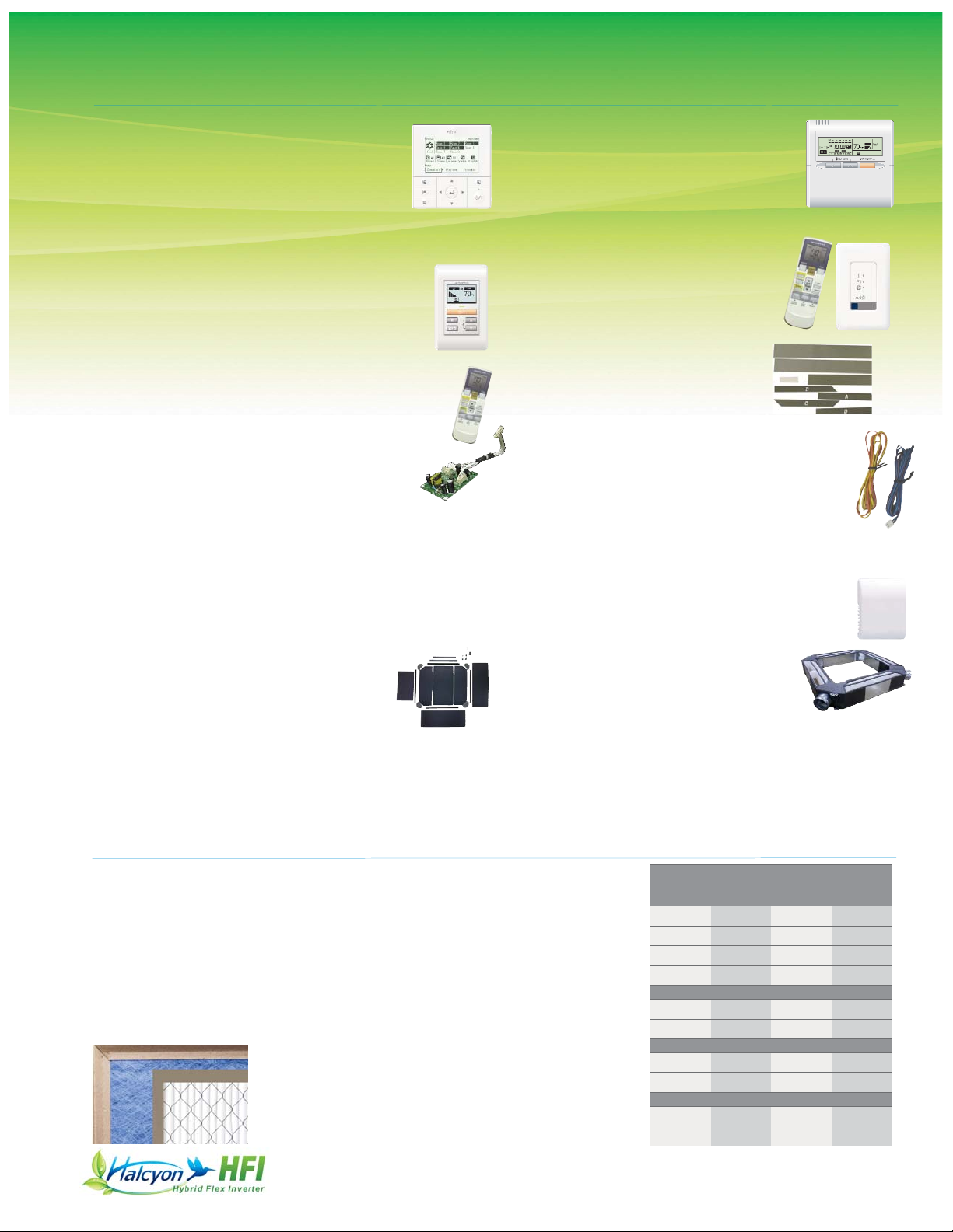
Central Remote Control
#UTY-DMMUM
This remote controls up to 8 individual indoor units
on a Hybrid Flex Inverter (HFI) system. Set
temperatures on timers to best meet individuals’
needs. The sleek design includes a large backlit
LCD and 4-way navigation pad. Remote connects in daisy
chain to branch boxes.
Simple Remote Control*
#UTY-RSNUM
Suitable when only basic operations are required for
hotels, offices and other places where there is
frequent arrival and departure of occupants. To be
used with all HFI indoor models.
Wired Remote Control for Wall Mounts*
#UTY-RNNUM
The wired remote controller with its unique
lock function and sleek design provides full
feature access to property managers, building owners, and facility maintenance, as well
as providing basic comfort features to
tenants, employees, and teachers.
Receiver Unit
#UTY-LRHUM
Includes a wireless remote control. For
use on slim duct Halcyon HFI indoor units
Field Supplied Filters Used With Slim Duct Units
Although Slim Duct units come with factory filters, when return
ductwork is used field supplied filters are more practical to use.
They can be installed at the unit or for more convenient servicing,
in filter grilles. The chart to the right provides guidelines for determining filter sizes.
The chart includes CFM, external static pressure capability and
a typical filter size for each model. Filters are sized to keep
velocities and static pressure loss low. This will insure sufficient
static pressure is available for ductwork, fittings and supply and
return grilles. Alternative filter sizes
with equivalent face areas can be
used. After deducting filter loss, available static pressure values are shown.
ARU
9RLF
ARU
12RLF
ARU
18RLF
ARU
24RLF
353 353 547 806
12 x 20 12 x 20 14 x 25 18 x 30
212 212 225 215
0.36 0.36 0.36 0.20
1" Fiberglass Filter
0.04 0.04 0.04 0.04
0.32 0.32 0.32 0.16
1" MERV 8 Pleated Filter
0.12 0.12 0.14 0.13
0.24 0.24 0.22 0.07
2" MERV 8 Pleated Filter
0.07 0.07 0.08 0.07
0.29 0.29 0.28 0.13
CFM
Typical Filter Size
Velocity, FPM
Unit External SP, in. W.C.
SP Loss, in. W.C.
Available Static Pressure
SP Loss, in. W.C.
Available Static Pressure
SP Loss, in. W.C.
Available Static Pressure
A fiberglass filter is shown in blue
to the left. A MERV pleated filter is
shown in white.
Wireless Remote Controller
#UTY-LNHUM
For spaces where there is just no place to mount the
wired remote. For use only with HFI compact cassettes.
Optional Accessories
* Wall mounted ASU7, 9, and 12RLF require accessory interface kit (Part UTY-XCBXZ1) in
order to connect this device to them. Wall mounted ASU9, 12, and 15RLS2 require
accessory interface kit (Part UTY-TWBXF) in order to connect this device to them.
** Internal thermosensor function in Wired Remote UTY-RNNUM is disabled when using
this interface kit.
Air Outlet Shutter Plate for
Compact Cassettes #UTR-YDZB
In a 3-way air flow configuration an Air
Outlet Shutter Plate kit is required.
Fresh Air Intake Kit for Compact Cassettes
#UTZ-VXAA
Mixes room air then passes it through a heat
exchanger. Allows for a 4-inch flex duct
connection. Requires a field supplied duct booster fan
capable of 60 CFM at .2”W.C. or 90 CFM at .4”W.C. For
fan static pressure requirements, see installation manual.
High Humidity Insulation Kit for Compact Cassettes
#UTZ-KXGC
Additional insulation for compact cassette units,
which may be needed when they are installed
in high humidity areas.
Interface Kit
#UTY-XCBXZ1
Required to connect ASU7RLF, 9RLF and 12RLF to
Wired Remote # UTY-RNNUM, Dry Contact Wire Kit
# UTY-XWZX, and Simple Remote Control # UTY-RSNUM.
Dry Contact Wire Kit*
#UTY-XWZX and UTY-XWZXZ5
Turns system on or off using a normally closed circuit,
for example in home automation or BMS integration
of only On/Off operation, occupancy sensor or key
card switch or lead-lag control of other heating/cooling.
l
UTD-ECS5A Slim Duct Connector Kit
l
UTY-XWZXZ3 Outdoor Unit Input/Output Connector
l
UTY-XWZXZ4 Outdoor Unit Base Heater Connector
Remote Sensor
#UTY-XSZX
Wall mounted temperature sensor for slim duct models.
Interface Kit**
UTY-TWBXF
Required to connect the ASU9RLS2, ASU12RLS2 and
ASU15RLS2 to Wired Remote UTY-RNNUM, Dry Contact
Wire Kit UTY-XWZXZ5, and Simple Remote Control
UTY-RSNUM.
Page 10

Outdoor Unit
Branch Box
UTP-PU03B
Branch Box
UTP-PU03B
40 amp
disconnect
40 amp
HVACR
Breaker
= 3PST
= 2PST
Optional Disconnect Switch
(or where code requires)
Ground
15 amp
HVACR
Breaker
Power Supply
2 Wire + Ground*
*Alternate Branch Box Power Configurations (Not Shown):
Each Branch Box may be powered from a separate 15A dedicated HVACR breaker or from a single 15A
dedicated HVACR breaker using a daisy chain to connect to secondary branch boxes.
Ground
10
Wiring
Branch Box
UTP-PU03A
High Voltage
Communication
3 Wire + Ground
Power and
Communication
3 Wire + Ground
Central Remote
Control
18 - 20 AWG
Branch Box Terminal Connections
High Voltage Communication
from Condenser
Out to Secondary
Branch Box
Out to Secondary
Branch Box
Central Remote
Power
Supply
Out to
Indoor #1
Out to
Indoor #2
Out to
Indoor #3
Miswiring Detection
Errors Detected For...
l Miswired terminals
l
Incorrect indoor unit
l
Less than 2 or more than
8 indoor units
l Less than 39,000 or more
than 62,000 BTUs
Power
Supply
Out to
Indoor #1
Out to
Indoor #2
Out to
Indoor #3
Central Remote
In From Primary
Branch Box
Primary Branch Box
Secondary Branch Box
Main Breaker
40
15
208-230
Power Supply
Junction Box
UTY-DMMUM
Page 11

Outdoor Unit
Branch Box
Separation Tube
Assembly Kit
Liquid pipe Adaptor Gas pipe
Branch Box to Indoor
7,000 BTU
1/4 inch
included
3/8 inch9,000 BTU included
12,000 BTU included
18,000 BTU n/a 1/2 inch
24,000 BTU included 5/8 inch
Calculate
Refrigerant Charge
Factory Charge 7.6 lb (3.45 kg)
Unit pre-charged to 0 feet
Pipe Diameter Location Additional Refrig.
3/8” Outdoor to Branch Box 0.624 oz./ft. or 58g/meter
1/4” Branch Box to Indoor Unit 0.224 oz./ft. or 21g/meter
(Total length of 3/8” liquid line × 0.624 oz./ft. or 58g/meter ) + (Total length of 1/4” liquid line × 0.224 oz./ft. or 21g/meter )
(a+b+c+d+e) × 0.624 oz./ft. or 58g/meter + (f+g+h+i+j+k+l+m) × 0.224 oz./ft. or 21g/meter = additional refrigerant
Liquid pipe 3/8 inch
Gas pipe 5/8 inch
=
**
* Distance between outdoor unit & farthest indoor unit.
** Total liquid pipe or total gas pipe.
Branch Box
Branch Box
11
Piping
Flare connections
=
Height difference between
outdoor and indoor units
98’ max.
49’
max.
Branch Box
Branch Box
Height difference
between indoor
and indoor units
49’ max.
1’ min.
Actual pipe length 230’ max.*
Total Pipe Length
377’ max.**
Flare connections
=
Liquid pipe 1/4 inch
Gas pipe 3/8”, 1/2”, or 5/8”
based on indoor unit size*
=
*Branch box outlets are all 1/2” on gas pipe connections.
1/2” to 3/8” adaptors and 1/2” to 5/8” adaptors included (3 of each).
Max. piping length
between outdoor unit
and farthest branch box
180’ max.
Height difference between
branch boxes
Pipe length
between
branch box
and farthest
indoor unit
49’
max.
fgh
ijk
lm
a
b
c
e
d
17’ min.
16’
min.
Page 12

24,000 BTU
9,000 BTU
7,000 BTU
Residential 1-story home
Church/School
Residential 2-story home
BRANCH BOX
KEY:
Central Remote
Features
l Efficient Mode
l Central Control
l Monitor Up To 8
Zones
l LCD Display
l 4-way Navigation
Pad
Examples
Fujitsu General America, Inc.
353 Route 46 West
Fairfield, NJ 07004
Toll Free: (888) 888-3424
Local: (973) 575-0380
Fax: (973) 836-0447
Email: hvac@fujitsugeneral.com
www.fujitsugeneral.com
A subsidiary of
Fujitsu General Limited
The Fujitsu logo is a registered trademark of Fujitsu Limited. The Halcyon HFI logo and name is a trademark
of Fujitsu General America, Inc. Copyright © 2012 Fujitsu General America, Inc.
PLEASE NOTE: Internet sales are strictly prohibited and unauthorized. Any HVAC systems purchased on the
Internet, from an online retailer or any similar e-tailing website, OR where the original factory serial numbers of the
display have been removed, defaced, or replaced in any way WILL NOT BE COVERED BY WARRANTY.
Printed in the USA Rev. 11/12
Part #6-26-FG2034
 Loading...