

Page 1
SPLIT TYPE
AIR CONDITIONER
CASSETTE TYPE (50Hz)
Indoor unit Outdoor unit
AUXG18LRLB
AUXG24LRLB
UTG-UKYA-W
AOYG18LBCA
AOYG24LBCA
CONTENTS
SPECIFICATIONS. . . . . . . . . . . . . . . . . . . .
1
DIMENSIONS . . . . . . . . . . . . . . . . . . . . . . .
2
REFRIGERANT SYSTEM DIAGRAM. . . . .
4
CIRCUIT DIAGRAM . . . . . . . . . . . . . . . . . .
5
ERROR DETECTION . . . . . . . . . . . . . . . .
6
PCB CIRCUIT DIAGRAM. . . . . . . . . . . . . .
8
. . . . . . . . . . . . . .
14
PARTS (OUTDOOR UNIT)
PARTS (INDOOR UNIT)
. . . . . . .
10
PARTS (DECORATION PANEL)
. . . . . . . . . . . .
19
ACCESSORIES . . . . . . . . . . . . . . . . . . . .
22
Page 2

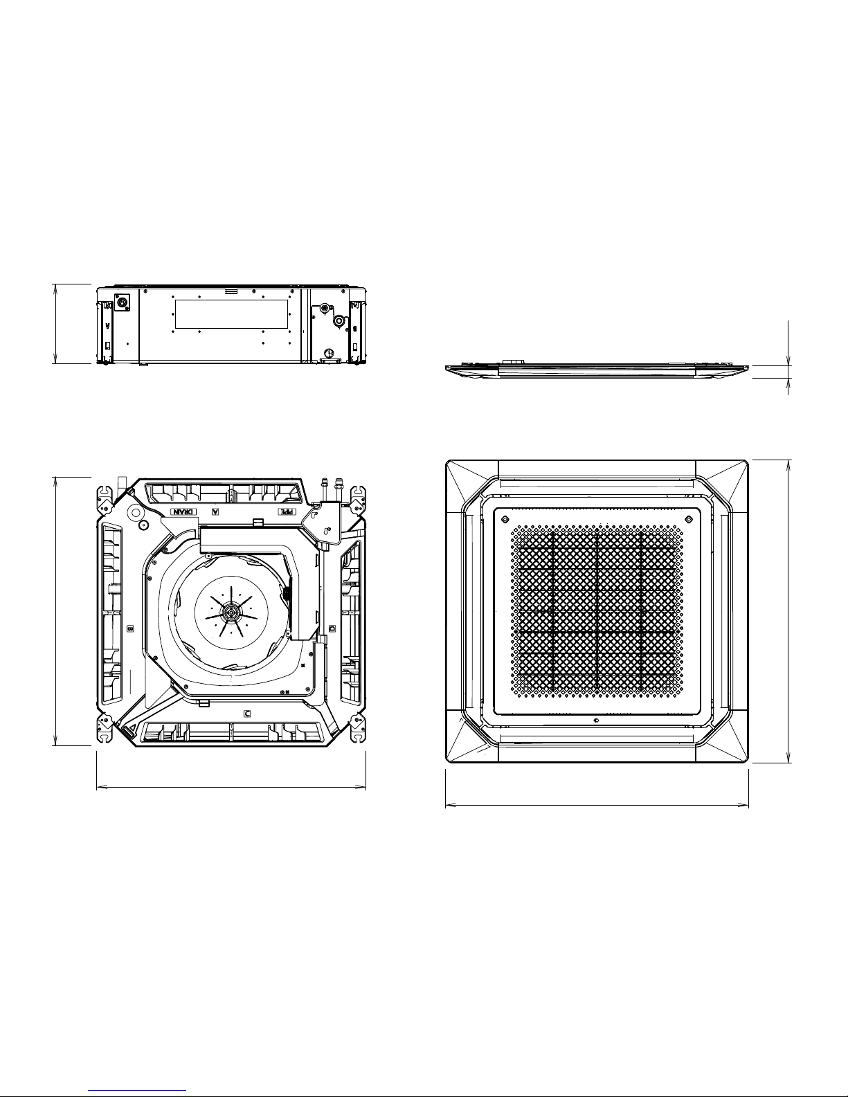
INDOOR UNIT H x W x D
H x W x D
H x W x D
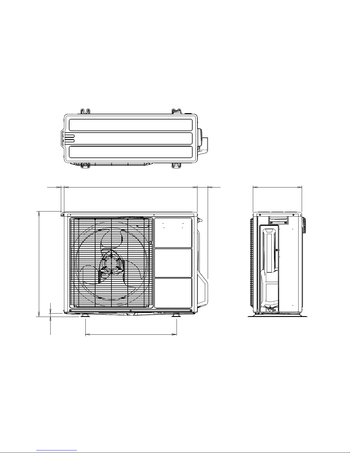
OUTDOOR UNIT
DIMENSIONS
INDOOR UNIT
DECORATION PANEL
DECORATION PANEL
Net / Shipping
Net / Shipping
Net / Shipping
OUTDOOR UNIT
WEIGHT
POWER SOURCE
OPERATING CURRENT
OPERATING CURRENT
CoolingHeating
POWER CONSUMPTION
POWER CONSUMPTION
EER
COP
DEHUMIDIFICATION
TYPE
Cooling & Heating
INDOOR UNIT
DECORATION PANEL UTG-UKYA-W
AUXG18LRLB
OUTDOOR UNIT
AOYG18LBCA
CAPACITY
CAPACITY
246 x 840 x 840 mm
53 x 950 x 950 mm
24 kg / 29 kg
6.0 kg / 10.5 kg
6.2 A
6.6 A
1.42 kW
1.50 kW
3.66 kW/kW
4.00 kW/kW
2.2 L/h
MAXIMUM CURRENT
MAXIMUM CURRENT
13.5 A
10.0 A
230 V, 50 Hz, Single phase
5.20 kW
6.0 kW
AUXG24LRLB
AOYG24LBCA
9.5 A
9.6 A
2.16 kW
2.18 kW
3.15 kW/kW
3.58 kW/kW
2.7 L/h
18.5 A
13.5 A
6.80 kW
7.8 kW
FAN MOTOR
INDOOR UNIT
OUTDOOR UNIT
MFF-T80VA2F
FAN REVOLUTION
High
INDOOR
UNIT
Medium
Low
400 rpm
360 rpm
340 rpm
Quiet
300 rpm
780 rpm
870 rpm
ELECTRICAL DATA
COMPRESSOR TYPE
DISCRIMINATION
WEIGHT (with oil)
PRECHARGED REFRIGERANT
REFRIGERANT TYPE
R410A
COMPRESSOR AND REFRIGERANT
2015.12.11 1
SPECIFICATIONS
MAXIMUM PIPING HEIGHT DIFFERENCE
Piping length
FULL CHARGE
ADDITIONAL CHARGE
AIR CIRCULATION
High
INDOOR
UNIT
Medium
Low
Cooling
Heating
1,050 m3/h
960 m3/h
900 m3/h
Quiet
780 m3/h
OUTDOOR
UNIT
Cooling
Heating
OUTDOOR
UNIT
1,900 m3/h 2,460 m3/h
1,700 m3/h
NOISE LEVEL
High
INDOOR
UNIT
Medium
Low
Cooling
Heating
33 dB
32 dB
31 dB
Quiet 28 dB
OUTDOOR
UNIT
51 dB 55 dB
50 dB
430 rpm
400 rpm
360 rpm
330 rpm
1,050 rpm
1,100 rpm
1,150 m3/h
1,050 m3/h
980 m3/h
870 m3/h
2,340 m3/h
35 dB
33 dB
32 dB
29 dB
56 dB
MFE-71TVAL
1,800 g
1,800 g
20 m
620 x 790 x 290 mm
41 kg / 45 kg
15 m
20 m 1,900 g
25 m 2,000 g
30 m 2,100 g
20 g/m
Hermetic type,
6 pole, 3 phase,
DC inverter motor, Rotary
N-SF17ND1A
10.6 kg
Page 3
2015.11.25 2
950 mm 53 mm
950 mm
840 mm
840 mm246 mm
Drain pipe diameter
Inside : 20 mm
Outside : 26 mm
DIMENSIONS
INDOOR UNIT DECORATION PANEL
Page 4
2015.12.02 3
19.5
290 mm
790 mm
20
540 mm
620 mm
62
OUTDOOR UNIT
Page 5
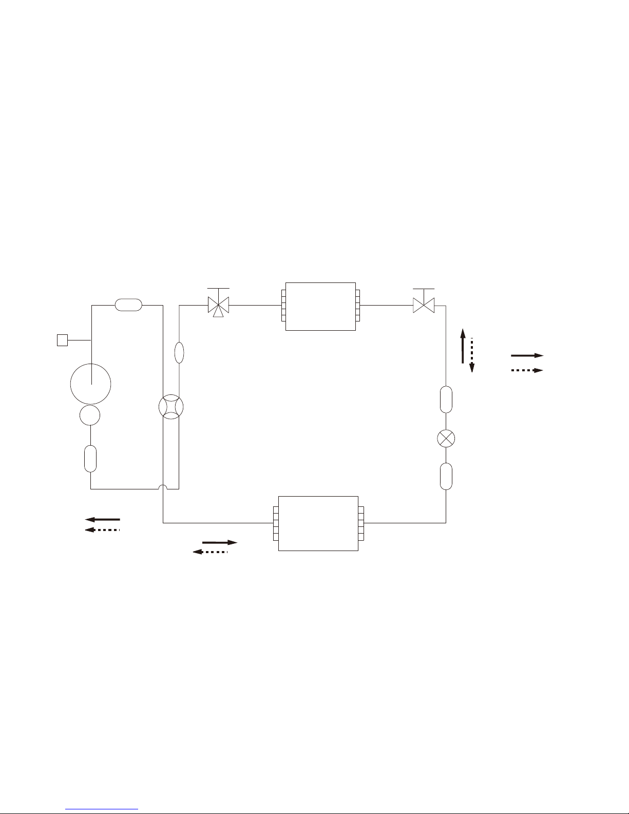
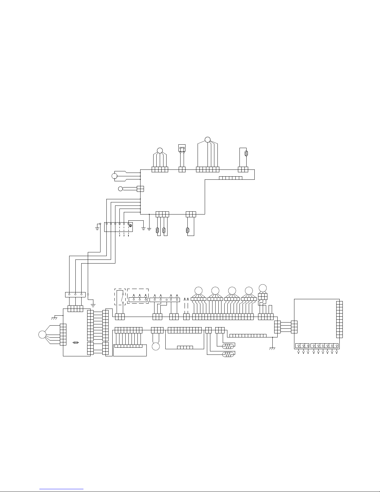
REFRIGERANT
SYSTEM DIAGRAM
2-way valve
Strainer
Strainer
3-way valve
Muffler
Muffler
Pressure
switch
4-Way valve
Expansion valve
Heat exchanger
(Indoor unit)
Heat exchanger
(Outdoor unit)
Sub-accumulator
Compressor
Cooling flow
Heating flow
Refrigerant pipe diameter
[18]
Liquid : 1/4” (6.35 mm)
Gas : 1/2” (12.7 mm)
[24]
Liquid : 1/4” (6.35 mm)
Gas : 5/8” (15.88 mm)
42015.11.24
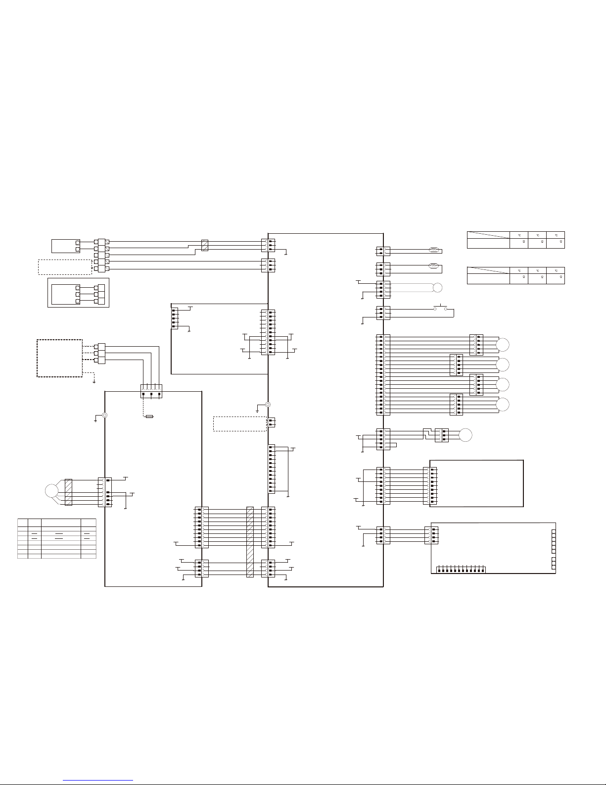
Page 6
Gray
Red
Orange
Yellow
Green
Black
Black
Red
Red
Red
White
White
White
Purple
Blue
Green
Yellow
Orange
Red
Gray
Black
Black
Black
White
Red
Blue
Orange
Red
Brown
Brown
Orange
Yellow
Gray
White
Orange
Brown
Orange
Green
Gray
Yellow
Yellow
Gray
Blue
Brown
Orange
Yellow
Gray
Blue
Red
Black
White
Black
White
Red
White
White
White
White
White
White
White
White
White
White
White
White
White
Yellow
Brown
White
Black
Red
Green
1 3 5 7 9 11 13151719 2 4 6 8 1012 14161820
1 3 5 7 9 11 13151719 2 4 6 8 1012 14161820
1 2 3 4 5 6 7 8 9 1011 12
1 2 3 4 5
1 2 3 4 5 6 7 8 9 1011
1 2 3 4 5 6 7 8 9 1011
1 2 3 4 5
1 2 3 4 5
1 2
1 2
1 2 3
1 2 3
1 2 3 4
1 2 3 4
1 2 3 4 5 6 7 8 9
1 2 3 4 5 6 7 8 9
1 2 3 4 5 6 7 8 9
1 2 3
1 2 3
1 2 3
1 2 3
1 2 3
1 2 3
1 2
1 2
1 2 3 4 5
1 2 3 4 5
1
2
3
4
5
6
7
8
9
10
11
12
1
2
3
4
5
6
7
8
9
10
11
12
1
2
3
4
CN8
TMB1
1
2
3
4
1
2
3
4
1
2
3
4
1
2
3
4
5
6
7
8
9
10
1
2
3
4
5
6
7
8
9
10
1
2
3
4
1
2
3
4
1
2
3
4
5
6
7
8
9
10
1
2
3
4
5
6
7
8
9
10
1
2
3
4
1
2
3
4
1
2
3
4
5
6
7
1
2
3
4
5
6
7
1 2 3
1 2 3
1 2 3 4 5 1 2 3 4 5 1 2 3 4 5 1 2 3 4 5
CN9
CN48
CN71
CN14 CN46 CN47 CN37 CN67
W100
CN73
CN32CN8
CN72
TMA1
CN9
CN2
CN1
CN54 CN55
CN65
CN301
CN370
CN304
CN303
W303
F300
Fuse
3.15A
250V
Y1
Y2
Y3
Y1
Y2
Y3
1 2
1 2 3 4 5 61
2 C
Thermistor
( Pipe temp. )
Thermistor
( Room temp. )
( Test )
Main PCB
M
S
M M
M
FMFan motor
Power supply
PCB
1 2 3
Float switch
Step motor
P. E. Sensor
(Option)
Ex. in and out board
( To Ex.in ) ( To Ex.out )
( Test )
Terminal
( 3-Wire type )
To Remote control
( 2-Wire type )
Ex.in
Terminal
( Option )
Wire for
external
output
Trans board
non-polar 2-Wire
DC Drain pump
motor
M
Indicator PCB
( Option )
Black
Black
Brown or Blue
Red
Black
White
Yellow
Red
Red
Red
White
Yellow
Orange
Blue
Black
Black
Black
Black
Black
Black
Green
Black
Black
Black
White
Red
Black
White
Red
Black
White
Green
1 2 3 54 6 7
1 2 3
1 2 3
1 2 3 4
1 2 3 4
1 1
2 2
1 2 3 54
1 2 3 54
1 2
1 2
1 2 3 54 6 7
1 2 3 54 6 7
1 2 3
1 2 3
R
T
S
CN40 CN74 CN800
CN600
CN73
CN70
CN71
W3
CN30
W101
W102
W4
W1
W2
W7 U
W8 V
W9 W
Fan motor
Expansion
valve coil
High pressure
switch
Thermistor
( Comp. temp. )
Compressor
4-way valve coil
Terminal
Earth
Power
source
1
23L
N
Main PCB
Thermistor
( Pipe temp. )
Thermistor
( Discarge temp. )
Thermistor
( Outdoor temp. )
CM
FM
PMV
4WV
OUTDOOR UNIT
INDOOR UNIT
CIRCUIT DIAGRAM
2015.11.20 5
Page 7
UL1015 AWG22
RED
BLACK
WHITE
YELLOW
BROWN
RED
RED
BLACK
BLACK
UL1007 AWG20
WHITE
RED
UL1007 AWG20
BLACK
BLACK
UL1061 AWG26
UL1430 AWG26
RED
BROWN
ORANGE
YELLOW
GRAY
WHITE
BROWN
ORANGE
YELLOW
GRAY
BLUE
BROWN
ORANGE
YELLOW
GRAY
GREEN
BROWN
ORANGE
YELLOW
GRAY
BLUE
PURPLE
WHITE
BLACK
WHITE
UL1061 AWG26
GRAY
RED
ORANGE
YELLOW
GREEN
BLUE
RED
BLACK
GRAY
RED
ORANGE
YELLOW
UL1430 AWG26
RED
UL1430 AWG22
WHITE
BLACK
WHITE
UL1061 AWG26
WHITE
WHITE
WHITE
WHITE
WHITE
WHITE
WHITE
WHITE
WHITE
UL1061 AWG22
WHITE
WHITE
WHITE
WHITE
UL1007 AWG22
UL1007 AWG22
RED
BLACK
BLUE
ORANGE
UL1015
AWG20
GREEN
TERMINAL
W303
EARTH
F300
3.15A
AC250V
UL1015
AWG20
GREEN
W100
EARTH
TERMINAL
CN37-1
CN37-3
CN37-5
CN37-7
CN37-9
CN37-11
CN37-13
CN37-15
CN37-17
CN37-19
CN37-2
CN37-4
CN37-6
CN37-8
CN37-10
CN37-12
CN37-14
CN37-16
CN37-18
CN37-20
CN67-1
CN67-2
CN67-3
CN67-4
CN67-5
CN48-1
CN48-2
CN48-3
CN48-4
CN48-5
CN48-6
CN48-7
CN48-8
CN48-9
CN65-1
CN65-2
CN65-3
CN65-4
CN72-1
CN72-2
CN72-3
CN72-4
CN72-5
CN72-6
CN72-7
CN72-8
CN72-9
CN72-10
CN72-11
CN47-1
CN47-2
CN73-1
CN73-2
CN73-3
CN73-4
CN73-5
CN73-6
CN73-7
CN73-8
CN73-9
CN73-10
CN73-11
CN73-12
CN55-1
CN55-2
CN55-3
CN55-4
CN55-5
CN55-6
CN55-7
CN55-8
CN55-9
CN55-10
CN54-1
CN54-2
CN54-3
CN54-4
CN1-1
CN1-2
CN1-3
CN1-4
CN1-5
CN1-6
CN1-7
CN1-8
CN1-9
CN8-1
CN8-2
CN8-3
CN8-4
CN9-1
CN9-2
CN9-3
CN9-4
CN9-5
CN9-6
CN9-7
CN9-8
CN9-9
CN9-10
CN9-11
CN9-12
CN370-1
CN370-4
CN370-5
CN370-6
CN370-7
CN1-1
CN1-2
CN1-3
CN1-4
CN1-5
CN2-1
CN2-2
CN2-3
CN2-4
CN2-5
CN2-6
CN2-7
CN2-8
CN2-9
CN2-10
CN2-11
CN71-1
CN71-2
CN71-3
CN71-4
CN9-1
CN9-2
CN9-3
CN32-1
CN32-2
CN32-3
CN8-1
CN8-2
CN46-1
CN46-2
CN46-3
CN14-1
CN14-2
CN14-3
CN304-1
CN304-2
CN304-3
CN304-4
CN304-5
CN304-6
CN304-7
CN304-8
CN304-9
CN304-10
CN303-1
CN303-2
CN303-3
CN303-4
CN301-1
CN301-3
CN301-5
CN14
B03B-XNISK-A-1
WHITE
CN46
B3B-XH-AM
WHITE
CN72
11R-JE
WHITE
CN47
B02B-PASK-1
WHITE
CN73
B12B-PASK-1
WHITE
CN55
B10B-PLIRK-1
RED
CN54
B04B-XNISK-A-1
WHITE
CN370
B5 ( 7-2.3 ) B-XASK-1-A
WHITE
CN8
B02B-XASK-1-A
WHITE
CN32
B03B-PASK-1
WHITE
CN71
B04B-XASK-1-A
WHITE
CN9
B03B-XARK-1-A
RED
CN37
SZW15-20WV-ET
WHITE
CN67
B05B-PASK-1
WHITE
CN48
B09B-PASK-1
WHITE
CN65
B04B-PASK-1
WHITE
CN304
B10B-PLIRK-1
RED
CN303
B04B-XNISK-A-1
WHITE
CN2
11PSL-JE
WHITE
CN1
SM05B-SRSS-TB
WHITE
CN301
B3 ( 5.0 ) B-XASK-1-A
WHITE
CN1
S09B-PASK-2
WHITE
CN8
B04B-PASK-1
WHITE
CN9
B12B-PASK-1
WHITE
TMB1
HP-T5338-1-6P
BLACK
TMA1
HP-T5338-1-3P
BLACK
SIGNAL1
SIGNAL2
COM
1-1
1-2
1-3
1-4
1-5
1-6
EMI FILTER
ZCAT3035-1330
3 TURNS
DC FAN MOTOR
DC DRAIN PUMP MOTOR
FLOAT SWITCH
THERMISTOR ( ROOM TEMP. )
THERMISTOR ( PIPE TEMP. )
PYROELECTRIC SENSOR
(Option)
REMOTE
CONTROL
( 3 WIRE )
3
2
1
Y1
Y2
Y3
Y1
Y2
Y3
1
2
M
INDOOR UNIT
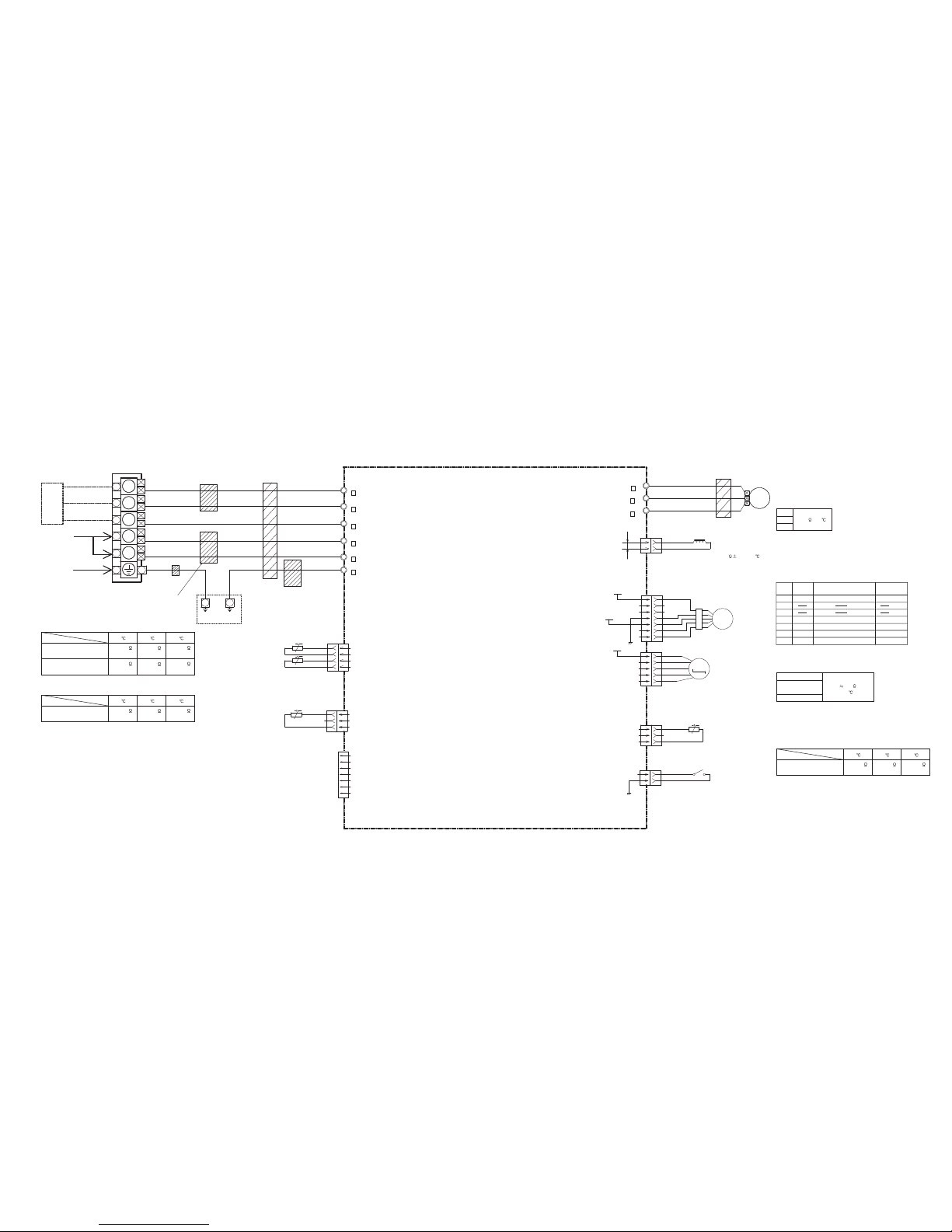
PCB CIRCUIT DIAGRAM
DC5V
DC12V
DC5V
DC12V
DC5V
DC12V-2
DC5V
DC12V
DC12V-2
DC5V
DC12V
DC15V
DC340V
DC5V
DC5V
DC5V
DC12V
DC12V
EMI FILTER
ZCAT1518-0730
1 TURN
EMI FILTER
ZCAT1518-0730
2 TURNS
TEST
AC IN
INDICATOR PCB
K14VE-1400HSE-D0
( OPTION )
EXTERNAL IN & OUT PCB
EX. SIGNAL. OUT
EX. SIGNAL. IN
REMOTE
CONTROL
( 2 WIRE )
EXTERNAL INPUT
OPTION ( 3 WIRE TYPE )
OUTDOOR UNIT
POWER SOURCE
AC230V
50Hz
POWER SUPPLY PCB
K14UZ-1400HSE-P0
MAIN PCB
AUXG18LRLB : K14UY-1509HSE-C1
AUXG24LRLB : K14UY-150AHSE-C1
FLASH
COMMUNICATION PCB
( NON - POLAR 2-WIRE )
K14VS-1400HSE-CA0
FM
P.E.
SENSOR
STEP MOTOR ( LOUVER 1 )
STEP MOTOR ( LOUVER 2 )
STEP MOTOR ( LOUVER 4 )
STEP MOTOR ( LOUVER 3 )
M
M
M
M
CN32
Thermistor Characteristics.
Thermistor ( Pipe - mid. temp. )
176.0 k
62.9 k
39.6 k
1.1 V
2.2 V 2.8 V
(20 ) (30 )
( 0 )
Thermistor
Temperature
CN8
Thermistor Characteristics.
Thermistor ( Room temp. )
33.6 k
12.5 k
8.0 k
1.1 V
2.2 V 2.8 V
(20 ) (30 )
( 0 )
Thermistor
Temperature
CN370 DC Fan motor
1
2
Pin No.
Terminal
code
Vm
Function of terminal
Motor power voltage input
Lead wire
color
Red
3
4
5
6
7
GND
Vcc
Vsp
FG
Revolution pulse output
Speed control voltage input
Control power voltage input
GND
Black
White
Yellow
Brown
CONTROL UNIT
AUXG18LRLB : EZ-015WHSE
AUXG24LRLB : EZ-015YHSE
2015.12.01 6
OPTION UNIT
( WIRE FOR EXTERNAL OUTPUT )
B
B
B
B
B
B
B
A
B
B
B
B
DC12V-3
2 WIRE TYPE
Page 8
1
2
3
4
5
6
7
1
2
3
1
2
3
4
1
2
3
4
5
6
7
1
2
3
4
5
1
2
3
1
2
1
2
W3
B
W2
B
W1
B
W4
B
W102
B
W101
B
W7
B
U
W8
B
V
W9
B
W
UL3271
AWG16
RED
UL3271
AWG16
WHITE
UL3271
AWG16
BLACK
BLACK
BLACK
COMPRESSOR
DC FAN MOTOR
EXPANSION VALVE COIL
THERMISTOR ( COMPRESSOR TEMP. )
PRESSURE SWITCH
RED
BLACK
WHITE
YELLOW
BROWN or BLUE
RED
BLUE
ORANGE
YELLOW
WHITE
BLACK
BLACK
RED
RED
UL1015
AWG18
BLACK
UL1015
AWG18
WHITE
UL1015
AWG20
RED
UL1015
AWG14
BLACK
UL1015
AWG14
WHITE
UL1015
AWG16
GREEN
BLACK
BLACK
BLACK
BLACK
BLACK
BLACK
1
2
3
4
5
L
N
SERIAL
TO I NDOOR UNIT
EARTH
POWER SOURCE
AC230V
50Hz
TERMINAL
FRAME FRAME
WIRE w / TERMINAL ( CORE )
1015#22
GREEN
THERMISTOR ( PIPE TEMP. )
THERMISTOR ( DISCHARGE TEMP. )
THERMISTOR ( OUTDOOR TEMP. )
CN71
B04B-PL I RK-1
RED
CN70
B03B-PL I SK-1
WHITE
CN600
B6 ( 7-3 ) B-XN I RK-B-2
RED
CN40
B05B-PL I SK-1
WHITE
CN800
B5 ( 7-2.3 ) B-XASK-1-A
WHITE
CN73
B03B-XN I SK-A-1
WHITE
CN74
1-1871843-2
RED
CN30
2-1747052-3
BLUE
C M
F M
M
EMI FILTER
ZCAT1518-0730
1 TURN
EMI FILTER
ZCAT1518-0730
1 TURN
EMI FILTER
TRCB-25-15-12
1 TURN
EMI FILTER
ZCAT3035-1330
1 TURN
EMI FILTER
TRCB-25-15-12
1 TURN
MAIN PCB
AOYG18LBCA : K11BS-1501HUE-C1
AOYG24LBCA : K11BS-1502HUE-C1
2015.09.15 7
OUTDOOR UNIT
U-V
V-W
U-W
Winding Resistance
0.818
(20 )
CN800 DC FAN MOTOR
1
3
4
5
6
Pin No.
Terminal
code
Vm
GND
Vcc
Vsp
FG
Function of terminal
Revolution pulse output
Speed control voltage input
Control power voltage input
GND
Motor power voltage input
Lead wire
color
Red
Black
White
Yellow
Brown or blue
2
7
1(Red) - 2(Blue)
1(Red) - 3(Orange)
1(Red) - 4(Yellow)
1(Red) - 5(White)
CN40 EXPANSION VALVE COIL
46.0
(20 )
Recommended Drive Condition
Unipolar Drive, 1-2 Phase Excitation.
Coil resistance
4-WAY VALVE COIL
*DC Resistance
2085
(20 )
10%
AC230V
( ON )
DC12V
DC340V
DC15V
CN73
Thermistor Characteristics.
Thermistor ( Compressor temp. )
168.6 k
64.5 k
41.1 k
0.3 V
0.8 V 1.2 V
(20 ) (30 )
( 0 )
Thermistor
Temperature
CN70
Thermistor Characteristics.
Thermistor ( Outdoor temp. )
35.2 k
12.6 k
8.0 k
2.6 V
3.8 V 4.1 V
(20 ) (30 )
( 0 )
Thermistor
Temperature
CN71
Thermistor Characteristics.
Thermistor ( Pipe temp. )
16.1 k
6.0 k
3.8 k
1.1 V
2.2 V 2.8 V
(20 ) (30 )
( 0 )
Thermistor
Temperature
Thermistor ( Discharge temp. )
168.6 k
64.5 k
41.1 k
0.3 V
0.8 V 1.2 V
INVERTER ASSEMBLY
AOYG18LBCA : EZ-015FHUE
AOYG24LBCA : EZ-015GHUE
Page 9

ERROR DETECTION
1.
If an error occurs, an error icon appears on the “Monitor mode screen”.
Touch the [Status] button. The “Status” screen is displayed.
2.
Touch the [Error Information] button. The “Error Information” screen is displayed.
(When there are no errors, the [Error Information] will not be displayed.)
3.
Double-digit numbers correspond to the error code in the table next page.
Touch the [Nex t page] (or [Previous page]) to switch to the other connected indoor units.
1. 2. 3.
Error code Contents
CC.1 Sensor error
Triple-digit error code means the error of remote control itself.
C2.1 Transmission PCB error
12.1 Wired remote control communication error
12.3 Number excess of device in wired remote control system
12.4 Wired remote control system star t-up error
26.4 Address duplication in wired remote control system
26.5 Address setting error in wired remote control system
15.4 Data acquisition error
Troubleshooting at the remote control LCD
Status
Air Flow Direction
VT
Off
1
Economy
Individual
Page 1/ 4
Monitor
Next
Page
Error
Information
UTY-RNRYZ1 (2-wire type)
Error icon
Double-digit numbers are corresponding to the
error code for the indoor unit or outdoor unit.
Touch to switch to the other
indoor unit information.
Error History (Triple-digit)
(1) Touch the [Error History] on
the “Maintenance” screen.
Back
Next
Page
Page 1/ 3
Maintenance
Error History
Setting
Status List
Version
Filter Sign
Reset
(2) “Error History” screen is displayed. When the screen
has multiple pages, they can be switched by touching
the [Next Page] or [Previous Page].
11:00
2:53
8:53
11:00
11:00
11:00
1
2015/ 8/ 1 002-01 141
2
2015/ 7/30 002-02 143
3
2015/ 7/25 002-02 143
4
2015/ 7/22 002-01 141
5
2015/ 7/22 002-01 141
6
2015/ 7/21 002-01 141
Page 1/ 2
Error History
No. Date Time Address Code
Back
Next
Page
Erase
All
AM
AM
AM
AM
AM
AM
11:00
2:53
8:53
11:00
11:00
7
2015/ 7/ 1 002-01 141
8
2015/ 7/10 002-02 143
9
2015/ 7/ 5 002-02 143
10
2015/ 7/ 2 002-01 141
11
2015/ 7/ 2 002-01 141
Page 2/ 2
Error History
No. Date Time Address Code
Back
Previous
Page
Erase
All
AM
AM
AM
AM
AM
(3) When the [Back] is touched after verifi cation, the display
returns to the “Maintenance” screen.
Erase the Error History
2015.06.12 8
(1) Touch the [Erase All] on the “Error History ” screen.
(2) A verifi cation screen is displayed. When the [Yes] is
touched after the histor y is cleared, the display returns
to the “Error History” screen.
)2( )1(
11:00
2:53
8:53
11:00
11:00
11:00
1
2015/ 8/ 1 002-01 141
2
2015/ 7/30 002-02 143
3
2015/ 7/25 002-02 143
4
2015/ 7/22 002-01 141
5
2015/ 7/22 002-01 141
6
2015/ 7/21 002-01 141
Page 1/ 2
Error History
No. Date Time Address Code
Back
Next
Page
Erase
All
AM
AM
AM
AM
AM
AM
Delete entire error history?
Error History
No Yes
Page 10

Error display
Wired
remote
controller
Error code
Description
OPERATION
lamp (green)
TIMER
lamp
(orange)
ECONOMY
lamp
(green)
(1)
(1)
Serial communication error
(1)
(2)
Wired remote controller
communication error
(1)
(5)
Check run un nished
(1)
(6)
Peripheral unit transmission PCB
connection error
(1)
(8)
External communication error
(2)
(1)
Unit number or Refrigerant circuit
address setting error
[Simultaneous Multi]
(2)
(2)
Indoor unit capacity error
(2)
(3)
Combination error
(2)
(4)
• Connection unit number
error (indoor secondary unit)
[Simultaneous Multi]
• Connection unit number error
(indoor unit or branch unit)
[Flexible Multi]
(2)
(6)
Indoor unit address setting error
(2)
(7)
Primary unit, secondary unit setup
error [Simultaneous Multi]
(2)
(9)
Connection unit number error in
wired remote controller system
(3)
(1)
Power supply interruption error
(3)
(2)
Indoor unit PCB model
information error
(3)
(5)
Manual auto switch error
(3)(10)
Indoor unit communication circuit
(wired remote controller) error
(4)
(1)
Room temp. sensor error
(4)
(2)
Indoor unit Heat Ex. Middle temp.
sensor error
(4)
(4)
Human sensor error
(5)
(1)
Indoor unit fan motor error
(5)
(3)
Drain pump error
(5)
(7)
Damper error
(5)(15)
Indoor unit error
2015.11.20 9
(6)
(1)
Outdoor unit reverse/missing
phase and wiring error
(6)
(2)
Outdoor unit main PCB
model information error or
communication error
(6)
(3)
Inverter error
(6)
(4)
Active lter error, PFC circuit error
(6)
(5)
Trip terminal L error
(6)
(8)
Outdoor unit rush current limiting
resister temp. rise error
(6)(10)
Display PCB microcomputers
communication error
(7)
(1)
Discharge temp. sensor error
(7)
(2)
Compressor temp. sensor error
(7)
(3)
Outdoor unit Heat Ex. liquid temp.
sensor error
(7)
(4)
Outdoor temp. sensor error
Error display
Wired
remote
control
Error code
Description
OPERATION
lamp (green)
TIMER
lamp
(orange)
ECONOMY
lamp
(green)
(7)
(5)
Suction Gas temp. sensor error
(7)
(6)
• 2-way valve temp. sensor error
• 3-way valve temp. sensor error
(7)
(7)
Heat sink temp. sensor error
(8)
(2)
• Sub-cool Heat Ex. gas inlet
temp. sensor error
• Sub-cool Heat Ex. gas outlet
temp. sensor error
(8)
(3)
Liquid pipe temp. sensor error
(8)
(4)
Current sensor error
(8)
(6)
• Discharge pressure sensor error
• Suction pressure sensor error
• High pressure switch error
(9)
(4)
Trip detection
(9)
(5)
Compressor rotor position
detection error (permanent stop)
(9)
(7)
Outdoor unit fan motor 1 error
(9)
(8)
Outdoor unit fan motor 2 error
(9)
(9)
4-way valve error
(9)(10)
Coil (expansion valve) error
(10)(1)
Discharge temp. error
(10)(3)
Compressor temp. error
(10)(4)
High pressure error
(10)(5)
Low pressure error
(13)(2)
Branch boxes error
[Flexible Multi]
Display mode
: 0.5s ON / 0.5s OFF
: 0.1s ON / 0.1s OFF
( ) : Number of flashing
If you use a wired type remote control,
error codes will apear on the remote control display.
When you use a wireless remote control,
the lamps on the IR receiver unit will output error codes
by way of blinking patterns.
See the lamp blinking patterns and error codes in the table.
An error display is displayed only during running.
UTY-RNRYZ1
Double-digit error code means the error for
the indoor unit or outdoor unit.
Page 11

1
Corner Panel Assy2
Remote Control (no brand)
2015.11.25
PARTS
DECORATION PANEL
UTG-UKYA-W
10
9381711000
9709335055
3 Intake Grille Assy Printed 9381690008
Ref. Description
Part number
1
3
2
Page 12

Panel metal
Grille metal
11
Switch Holder
12
Longlife Filter
13
Filter Guide
14 Switch Spring
2015.10.26
DECORATION PANEL
UTG-UKYA-W
Intake grille assy
9378252028
9378253018
9381362004
9381688005
15 Switch 9381363001
Ref. Description
Part number
12
13
15
11
14
11
Page 13

21 Louver Assy
22 Motor Cover
25 Motor Case
26 Drain Cover Assy
24 Shaft Cover
23 Step Motor
2015.10.23
DECORATION PANEL
UTG-UKYA-W
9381693009
9381354009
27 Bezel 9381353002
9381356003
9381713004
9381357000
9900885007
Ref. Description
Part number
24
25
21
27
26
23
22
12
Page 14

31 Hook Wire
32 Panel Insulation A
35 Decoration Panel
34 Panel insulation C
33 Panel Insulation B
2015.10.26
DECORATION PANEL
UTG-UKYA-W
9378597020
9381359004
9381352005
9381355006
9381360000
Ref. Description
Part number
34
33
32
31
35
13
Page 15

PARTS
INDOOR UNIT
AUXG18LRLB
AUXG24LRLB
2015.11.25 14
Hook A
Hook B
Wire cover
Hook A
Page 16

5
Main PCB (AUXG18LRLB)
Box shield
INDOOR UNIT
AUXG18LRLB
AUXG24LRLB
2015.11.24 15
9710016165
5
Main PCB (AUXG24LRLB)
9710016172
1 Cable Guide
2 Room Thermistor Holder
9381376001
9381348008
2
Ref. Description Part number
6
7
5
11
10
1
8
9
3 Room Thermistor
4 Pipe Thermistor
9900822002
9900903008
6 Power PCB
7 PCB (Non-polar 2-wire)
9710022005
10 Main PCB Holder 9381350001
11 Power PCB Holder 9381349005
9710019005
8 Remote Terminal 5P
9 Power Terminal 3P
9900896003
9900720032
3
4
Page 17

21 Bellmouth
22 Turbo Fan Assy
24 Nut
25 Brushless Motor
2015.11.25
INDOOR UNIT
AUXG18LRLB
AUXG24LRLB
9381484003
9381303007
9356998009
23 Turbo Fan Washer 9378394018
28 Drain Pan Sub Assy 9381789009
9603443009
27 Motor Wire Holder
26 Special Nut
9381351008
9378388017
Ref. Description
Part number
24
21
25
22
26
23
16
27
28
Page 18

2015.11.25
Hang the lead in the hook.
Make a slack.
Hang the fan motor lead in the drain pan hooks.
(when it is maintained)
Tuck the lead.
Drain pan
Lead
Not to be loosed.
Page 19

31 Drain Cap
2015.11.25 17
INDOOR UNIT
AUXG18LRLB
AUXG24LRLB
9375502010
31
39
33 Vane L
34 Vane R
39 Float Switch Sub Assy
38 Hose Band
36 Drain Port Sub Assy
9381745012
9381744008
32 Panel Hook 9375671013
37 Drain Hose 9379665001
35 Drain Pump Sub Assy 9381793006
9381794003
9379757010
9381788002
Ref. Description
Part number
34
32
33
35
36
37
38
Page 20

INDOOR UNIT
AUXG18LRLB
AUXG24LRLB
42
Insulation Box Sub Assy
Pipe cover
2015.11.25 18
43 Wind Guide Board 9382125004
9378580121
41
Cabinet B
sub assy
Cabinet A L
9381787012
Top plate assy
Evaporator holder
Ref. Description
Part number
Evaporator Total Assy (18)
42 9378580114Evaporator Total Assy (24)
41
42
43
Page 21

OUTDOOR UNIT
AOYG18LBCA
AOYG24LBCA
PARTS
2015.11.24 19
6 Front Panel Assy 9318463040
4 Top Panel Assy 9318464139
3 Protective Net 9331640015
710Cabinet Left Assy 9318461015
5 Emblem 9319151007
1 Drain Assy 9303029022
Switch Cover Assy 9318499001
8 Cabinet Right Assy 9318462012
12 Propeller Fan 9313808013
2 Drain Cap
313166024302
9 Grip 9317588003
11 Fan Motor 9602724017
Ref. Description Part number
8
10
12
11
9
7
6
4
3
5
1
2
Page 22

25
27
26
OUTDOOR UNIT
AOYG18LBCA
AOYG24LBCA
2015.11.24 20
25 Outdoor Thermistor 9900565008
27
Compressor Thermistor
9900777012
Terminal
bracket
24 Terminal 6P 9900435028
26 Thermistor Assy 9900727017
Shield panel
Inverter case assy
Main PCB (18LBCA)22 9708995342
Main PCB (24LBCA)22 9708995359
23 Heat Sink 9319540009
21 PCB Holder 9319547015
Ref. Description Part number
24
22
21
23
Page 23

OUTDOOR UNIT
AOYG18LBCA
AOYG24LBCA
2015.11.24 21
32 Compressor 9810244000
34 3-way Valve Sub Assy (24) 9319098005
34 3-way Valve Sub Assy (18) 9317109017
37 Pulse Motor Valve Sub Assy 9319886022
36 Solenoid 9970110023
31 Condenser Total Assy 9317089166
38 Expansion Valve Coil 9970095030
35 4-way Valve Assy 9319874012
33 2-way Valve Assy 9314554018
Ref. Description Part number
36
35
37
38
33
34
32
31
Page 24

Name and shape Q’ty Description
Hexagon Screw
4
For mounting decoration panel
Washer
4
For mounting decoration panel
Tapping screw
2
For installing grille holding wire
Strap
4
For installing corner panel
DECORATION PANEL
UTG-UKYA-W
INDOOR UNIT
AUXG18LRLB
AUXG24LRLB
2015.11.24
ACCESSORIES
22
Name and shape Q’ty Name and shape Q’ty
Wired remote control
WIRED REMOTE CONTROL
1
Screw (M4 × 16mm)
For installing the remote
control
2
Cable tie
For remote control and
remote control cable
binding
1
Name and Shape Q’ty Description
Template
(Carton top)
1
For installing indoor unit
Washer
8
For installing indoor unit
Coupler heat insulation (Large)
1
For indoor side pipe joint (Gas pipe)
Coupler heat insulation (Small)
1
For indoor side pipe joint
(Liquid pipe)
Insulation
1
For installing drain pipe
Drain hose
1
For installing drain pipe
VP25 (O.D.32, I.D.25)
Hose Band
1
For installing drain hose
Drain hose heat insulation
1
For installing drain pipe
Cable tie (Large)
4
For fixing the connection pipe
Cable tie (Small)
2
For electrical wiring
OUTDOOR UNIT
Name and shape Name and shapeQ’ty Q’ty
Drain pipe
1
Drain cap
3
Page 25

1509G4442
 Loading...