

Page 1

Installation Guide
English
SPARC® Enterprise T5140 / T5240 Servers
Page 2

Page 3

SPARC®Enterprise
T5140 and T5240 Servers
Installation Guide
Order No. U41767-J-Z816-1-76
Part No. 875-4310-10
February 2008, Revision A
Page 4

Copyright 2008 Sun Microsystems, Inc., 4150 Network Circle, Santa Clara, California 95054, U.S.A. All rights reserved.
FUJITSU LIMITED provided technical input and review on portions of this material.
Sun Microsystems,Inc. andFujitsu Limited eachown orcontrol intellectualproperty rightsrelating to products and technologydescribed in
this document,and such products, technology andthis documentare protectedby copyrightlaws, patents andother intellectualproperty laws
and internationaltreaties. Theintellectual propertyrights of SunMicrosystems, Inc.and FujitsuLimited in suchproducts, technologyand this
document include,without limitation, one or moreof theUnited States patents listed athttp://www.sun.com/patentsand oneor more
additional patentsor patent applications in theUnited Statesor other countries.
This documentand the product and technologyto whichit pertains are distributed underlicenses restrictingtheir use,copying, distribution,
and decompilation.No part of such product ortechnology,or ofthis document, may be reproduced inany formby any meanswithout prior
written authorizationof Fujitsu Limited and SunMicrosystems, Inc.,and their applicable licensors, ifany. Thefurnishing of this document to
you doesnot give you any rightsor licenses,express or implied, with respectto theproduct ortechnology to whichit pertains,and this
document doesnot contain or representany commitment ofany kindon the partof FujitsuLimited or Sun Microsystems, Inc.,or anyaffiliate of
either ofthem.
This documentand the product and technologydescribed inthis document may incorporate third-partyintellectual propertycopyrighted by
and/or licensedfrom suppliersto Fujitsu Limitedand/or SunMicrosystems, Inc.,including softwareand font technology.
Per theterms of the GPL orLGPL, acopy of thesource codegoverned bythe GPL orLGPL, asapplicable, is availableupon requestby theEnd
User.Please contactFujitsu Limited orSun Microsystems,Inc.
This distribution may include materials developed by third parties.
Parts of the product may be derived from Berkeley BSD systems, licensed from the University of California. UNIX is a registered trademark
in the U.S. and in other countries, exclusively licensed through X/Open Company, Ltd.
Sun, Sun Microsystems, the Sun logo, Java, Netra, Solaris, Sun StorEdge, docs.sun.com, OpenBoot, SunVTS, Sun Fire, SunSolve, CoolThreads,
J2EE, and Sun are trademarks or registered trademarks of Sun Microsystems, Inc. in the U.S. and other countries.
Fujitsu and the Fujitsu logo are registered trademarks of Fujitsu Limited.
All SPARC trademarks are used under license and are registered trademarks of SPARC International, Inc. in the U.S. and other countries.
Products bearing SPARC trademarks are based upon architecture developed by Sun Microsystems, Inc.
SPARC64 is a trademark of SPARC International, Inc., used under license by Fujitsu Microelectronics, Inc. and Fujitsu Limited
The OPEN LOOK and Sun™ Graphical User Interfacewas developed by Sun Microsystems, Inc. forits users and licensees. Sunacknowledges
the pioneering efforts of Xerox in researching and developing the concept of visual or graphical user interfaces for the computer industry. Sun
holds anon-exclusive license from Xeroxto the Xerox GraphicalUser Interface,which license alsocovers Sun’slicensees who implement OPEN
LOOK GUIs and otherwise comply with Sun’s written license agreements.
United StatesGovernment Rights - Commercial use.U.S. Governmentusers aresubject to thestandard governmentuser licenseagreements of
Sun Microsystems,Inc. andFujitsu Limited andthe applicableprovisions ofthe FAR andits supplements.
Disclaimer: The only warranties granted by Fujitsu Limited, Sun Microsystems, Inc. or any affiliate of either of them in connection with this
document or any product or technology described herein are those expressly set forth in the license agreement pursuant to which the product
or technology is provided. EXCEPT AS EXPRESSLY SET FORTH IN SUCH AGREEMENT, FUJITSU LIMITED, SUN MICROSYSTEMS, INC.
AND THEIRAFFILIATES MAKENO REPRESENTATIONS ORWARRANTIES OF ANY KIND(EXPRESS OR IMPLIED)REGARDING SUCH
PRODUCT OR TECHNOLOGY OR THIS DOCUMENT, WHICH ARE ALL PROVIDED AS IS, AND ALL EXPRESS OR IMPLIED
CONDITIONS, REPRESENTATIONS AND WARRANTIES, INCLUDING WITHOUT LIMITATION ANY IMPLIED WARRANTY OF
MERCHANTABILITY, FITNESS FOR A PARTICULAR PURPOSE OR NON-INFRINGEMENT, ARE DISCLAIMED, EXCEPT TO THE
EXTENT THAT SUCH DISCLAIMERS ARE HELD TO BE LEGALLY INVALID. Unless otherwise expressly set forth in such agreement, to the
extent allowed by applicable law, in no event shall Fujitsu Limited, Sun Microsystems, Inc. or any of their affiliates have any liability to any
third party under any legal theory for any loss of revenues or profits, loss of use or data, or business interruptions, or for any indirect, special,
incidental or consequential damages, even if advised of the possibility of such damages.
DOCUMENTATION IS PROVIDED “AS IS” AND ALL EXPRESS OR IMPLIED CONDITIONS, REPRESENTATIONS AND WARRANTIES,
INCLUDING ANYIMPLIED WARRANTY OF MERCHANTABILITY, FITNESS FOR APARTICULAR PURPOSE OR NON-INFRINGEMENT,
ARE DISCLAIMED, EXCEPT TO THE EXTENT THAT SUCH DISCLAIMERS ARE HELD TO BE LEGALLY INVALID.
.
Page 5

Copyright 2008 Sun Microsystems, Inc., 4150 Network Circle, Santa Clara, California 95054, Etats-Unis. Tous droits réservés.
Entrée et revue tecnical fournies par FUJITSU LIMITED sur des parties de ce matériel.
Sun Microsystems, Inc. et Fujitsu Limited détiennent et contrôlent toutes deux des droits de propriété intellectuelle relatifs aux produits et
technologies décrits dans ce document. De même, ces produits, technologies et ce document sont protégés par des lois sur le copyright, des
brevets, d’autreslois sur la propriétéintellectuelle et des traités internationaux. Les droits depropriété intellectuelle de SunMicrosystems, Inc.
et Fujitsu Limited concernant ces produits, ces technologies et ce document comprennent, sans que cette liste soit exhaustive, un ou plusieurs
des brevets déposésaux États-Unis et indiqués à l’adresse http://www.sun.com/patents de même qu’un ou plusieurs brevets ou applications
brevetées supplémentaires aux États-Unis et dans d’autres pays.
Ce document, le produit et les technologies afférents sont exclusivement distribués avec des licences qui en restreignent l’utilisation, la copie,
la distribution et la décompilation. Aucune partie de ce produit, de ces technologies ou de ce document ne peut être reproduite sous quelque
forme quece soit, parquelque moyen quece soit, sansl’autorisation écrite préalablede Fujitsu Limitedet de SunMicrosystems, Inc., etde leurs
éventuels bailleurs de licence. Ce document, bien qu’il vous ait été fourni, ne vous confère aucun droit et aucune licence, expresses ou tacites,
concernant le produitou la technologie auxquelsil se rapporte. Par ailleurs, il ne contient nine représente aucun engagement,de quelque type
que ce soit, de la part de Fujitsu Limited ou de Sun Microsystems, Inc., ou des sociétés affiliées.
Ce document, et le produit et les technologies qu’il décrit, peuvent inclure des droits de propriété intellectuelle de parties tierces protégés par
copyright et/ou cédés sous licence par des fournisseurs à Fujitsu Limited et/ou Sun Microsystems, Inc., y compris des logiciels et des
technologies relatives aux polices de caractères.
Par limites du GPL ou du LGPL, une copie du code source régi par le GPL ou LGPL, comme applicable, est sur demande vers la fin utilsateur
disponible; veuillez contacter Fujitsu Limted ou Sun Microsystems, Inc.
Cette distribution peut comprendre des composants développés par des tierces parties.
Des parties de ce produit pourront être dérivées des systèmes Berkeley BSD licenciés par l’Université de Californie. UNIX est une marque
déposée aux Etats-Unis et dans d’autres pays et licenciée exclusivement par X/Open Company, Ltd.
Sun, Sun Microsystems, le logo Sun, Java, Netra, Solaris, Sun StorEdge, docs.sun.com, OpenBoot, SunVTS, Sun Fire, SunSolve, CoolThreads,
J2EE, et Sun sont des marques de fabrique ou des marques déposées de Sun Microsystems, Inc. aux Etats-Unis et dans d’autres pays.
Fujitsu et le logo Fujitsu sont des marques déposées de Fujitsu Limited.
Toutes les marques SPARC sont utilisées sous licence et sont des marques de fabrique ou des marques déposées de SPARC International, Inc.
aux Etats-Unis et dans d’autres pays. Les produits portant les marques SPARC sont basés sur une architecture développée par Sun
Microsystems, Inc.
SPARC64 est une marques déposée de SPARC International, Inc., utilisée sous le permis par Fujitsu Microelectronics, Inc. et Fujitsu Limited.
L’interface d’utilisation graphique OPEN LOOK et Sun™ a été développée par Sun Microsystems, Inc. pour ses utilisateurs et licenciés. Sun
reconnaît les effortsde pionniers de Xerox pour la recherche et le développementdu concept des interfaces d’utilisation visuelleou graphique
pour l’industrie de l’informatique. Sun détient une license non exclusive de Xerox sur l’interface d’utilisation graphique Xerox, cette licence
couvrant également les licenciés de Sun qui mettent en place l’interface d’utilisation graphique OPEN LOOK et qui, en outre, se conforment
aux licences écrites de Sun.
Droits du gouvernement américain - logiciel commercial. Les utilisateurs du gouvernement américain sont soumis aux contrats de licence
standard de Sun Microsystems, Inc. et de Fujitsu Limited ainsi qu’aux clauses applicables stipulées dans le FAR et ses suppléments.
Avis denon-responsabilité: les seules garanties octroyéespar Fujitsu Limited,Sun Microsystems,Inc. ou toutesociété affiliée de l’une oul’autre
entité enrapport avec cedocument ou toutproduit ou toutetechnologie décrit(e) dans les présentes correspondent aux garantiesexpressément
stipulées dans le contrat de licence régissant le produit ou la technologie fourni(e). SAUF MENTION CONTRAIRE EXPRESSÉMENT
STIPULÉE DANS CE CONTRAT, FUJITSU LIMITED, SUN MICROSYSTEMS, INC. ET LES SOCIÉTÉS AFFILIÉES REJETTENT TOUTE
REPRÉSENTATION OU TOUTE GARANTIE, QUELLE QU’EN SOIT LA NATURE (EXPRESSE OU IMPLICITE) CONCERNANT CE
PRODUIT,CETTE TECHNOLOGIE OUCE DOCUMENT, LESQUELS SONT FOURNISEN L’ÉTAT. EN OUTRE,TOUTES LES CONDITIONS,
REPRÉSENTATIONS ET GARANTIES EXPRESSES OU TACITES, Y COMPRIS NOTAMMENTTOUTE GARANTIE IMPLICITERELATIVE À
LA QUALITÉ MARCHANDE, À L’APTITUDE À UNE UTILISATION PARTICULIÈRE OU À L’ABSENCE DE CONTREFAÇON, SONT
EXCLUES, DANS LA MESURE AUTORISÉE PAR LA LOI APPLICABLE. Sauf mention contraire expressément stipulée dans ce contrat, dans
la mesure autoriséepar la loi applicable, en aucun cas Fujitsu Limited,Sun Microsystems, Inc. oul’une de leurs filiales nesauraient être tenues
responsables envers une quelconque partie tierce, sous quelque théorie juridique que ce soit, de tout manque à gagner ou de perte de profit,
de problèmes d’utilisation ou de perte de données, ou d’interruptions d’activités, ou de tout dommage indirect, spécial, secondaire ou
consécutif, même si ces entités ont été préalablement informées d’une telle éventualité.
LA DOCUMENTATION EST FOURNIE “EN L’ETAT” ET TOUTES AUTRES CONDITIONS, DECLARATIONS ET GARANTIES EXPRESSES
OU TACITES SONT FORMELLEMENTEXCLUES, DANSLA MESURE AUTORISEE PAR LA LOIAPPLICABLE, Y COMPRIS NOTAMMENT
TOUTE GARANTIE IMPLICITE RELATIVE A LA QUALITE MARCHANDE, A L’APTITUDE A UNE UTILISATION PARTICULIERE OU A
L’ABSENCE DE CONTREFACON.
Page 6

Page 7

Contents
Preface xiii
1. Preparing for Installation 1
Tools and Equipment Needed 3
Optional Component Installation 3
ESD Precautions 3
Installation Overview 4
Cabling Notes for Both Servers 6
Port, Connector, and LED Locations for Both Servers 7
Slide Rail Assembly Notes for Both Servers 10
Cable Management Notes for Both Servers 13
Safety Precautions 14
2. Installing the SPARC Enterprise T5140 and T5240 Servers 15
Installing the Servers in a Rack 15
▼ To Install the Slide Rail Assemblies 16
▼ To Insert and Lock the Server in the Rack 22
Installing the Cable Management Arm for Both Servers 24
▼ To Install the Cable Management Arm 24
▼ To Verify the Operation of the Slide Rails and the CMA 29
v
Page 8

Connecting the Server Cables for Both Servers 31
▼ To Connect the Service Processor Serial Management Port 31
▼ To Connect the Service Processor Network Management Port 32
▼ To Connect the Ethernet Network Cables 33
▼ To Connect the AC Power Cable to the Server 34
Managing Cables With the CMA 34
▼ Securing the Server Cables in the CMA 35
Dismounting the Servers 35
3. Powering On the System 37
Powering On the System for the First Time 37
ILOM System Console 37
ILOM Service Processor 38
▼ To Power On the System for the First Time 38
Enabling the Service Processor Network Management Port 44
Logging Into the Service Processor 45
▼ To Log Into the Service Processor Using the Serial Management Port 45
▼ To Configure the Service Processor Network Management Port 47
▼ To Log Into the Service Processor Using the Network Management Port
50
Using the Service Processor for Common Operations 50
▼ To Power On the System 51
▼ To Connect to the System Console 53
▼ To Perform a Normal System Initialization 53
Devices in the OpenBoot Device Tree 55
Booting the Solaris Operating System 56
▼ To Boot the Solaris Operating System 56
▼ To Avoid Booting the Solaris Operating System at Start Up 57
▼ To Reset the System 57
vi SPARC Enterprise T5140 and T5240 Servers Installation Guide • February 2008
Page 9

▼ To Power Cycle the System 57
Verifying System Functionality 59
A. Updating the Firmware 61
The flashupdate command 61
Updating the Firmware 61
▼ To Update the Firmware 62
B. Selecting a Boot Device 65
Selecting a Boot Device 65
▼ To Select a Boot Device 66
C. Installing the Servers With the Express Rail Rackmounting Kit 67
Slide Rail Assembly Notes for the Express Rail Rackmounting Kit 68
Installing the Servers in a Rack With Express Rails 71
▼ To Install the Slide Rail Assemblies 71
▼ To Insert and Lock the Server in the Rack 76
Installing the Cable Management Arm 79
Connecting the Server Cables 79
Managing Cables With the CMA 79
Dismounting the Server 79
Index 81
Contents vii
Page 10

viii SPARC Enterprise T5140 and T5240 Servers Installation Guide • February 2008
Page 11

Figures
FIGURE 1-1 SPARC Enterprise T5140 Server 2
FIGURE 1-2 SPARC Enterprise T5240 Server 2
FIGURE 1-3 Rear Panel Cable Connectors and LEDs on the SPARC Enterprise T5140 Server 8
FIGURE 1-4 Front Panel USB Ports on the SPARC Enterprise T5140 Server 8
FIGURE 1-5 Rear Panel Cable Connectors and LEDs on the SPARC Enterprise T5240 Server 9
FIGURE 1-6 Front Panel USB Ports on the SPARC Enterprise T5240 Server 10
FIGURE 1-7 Sections of the Slide Rail Assembly on the SPARC Enterprise T5240 Server 11
FIGURE 1-8 Locating the Locks on the Slide Rail Assembly for the SPARC Enterprise T5240 Server 12
FIGURE 1-9 Cable Management Arm for Both Servers 13
FIGURE 2-1 Unlocking the Slide Rail Assembly (Either Server) 16
FIGURE 2-2 Location of the Mounting Bracket Release Button (Either Server) 17
FIGURE 2-3 Unlocking the Slide Rail Middle Section (Either Server) 18
FIGURE 2-4 Attaching a Mounting Bracket to the Chassis (Either Server) 19
FIGURE 2-5 Mounting a Slide Rail (Either Server) 20
FIGURE 2-6 Using the Slide Rail Spacing Tool to Adjust the Distance Between the Slide Rails (Either
Server) 21
FIGURE 2-7 Mounting the Chassis on the Slide Rails (Either Server) 23
FIGURE 2-8 Inserting the CMA Rail Extension Into the Rear of the Left Slide Rail (Either Server) 25
FIGURE 2-9 Mounting the Inner CMA Connector (Either Server) 26
FIGURE 2-10 Attaching the Outer CMA Connector (Either Server) 27
FIGURE 2-11 Mounting the Left Side of the Slide Rail (Either Server) 28
ix
Page 12

FIGURE 2-12 Unlocking the Slide Rail Assembly (Either Server) 29
FIGURE 2-13 Rail Mounting Bracket Release Button (Either Server) 30
FIGURE 2-14 Service Processor Serial Management Port – Rear Panel 32
FIGURE 2-15 Service Processor Network Management Port – Rear Panel 33
FIGURE 2-16 Service Processor Ethernet Network Ports – Rear Panel 34
FIGURE 2-17 Securing the Server Cables With the CMA and Velcro Straps (Either Server) 35
FIGURE 3-1 Server Connections 40
FIGURE C-1 Sections of the Express Rail Slide Rail Assembly 68
FIGURE C-2 Locating the Locks on the Slide Rail Assembly for the SPARC Enterprise T5240 Server 70
FIGURE C-3 Unlocking the Express Rail Slide Rail Assembly 72
FIGURE C-4 Express Rail Mounting Bracket Release Button 73
FIGURE C-5 Attaching an Express Rail Mounting Bracket to the Chassis 74
FIGURE C-6 Express Rail Slide Rails Orientation for Installation 75
FIGURE C-7 Attaching Express Slide Rails to the Rack 76
FIGURE C-8 Inserting Express Rail Mounting Brackets Into the Slide Rails 77
FIGURE C-9 Sliding the Express Rail Release Tab and Securing the Server in the Rack 78
x SPARC Enterprise T5140 and T5240 Servers Installation Guide • February 2008
Page 13

Tables
TABLE 1-1 Ethernet Connection Transfer Rates 7
TABLE 3-1 Disk Slot Numbers, Logical Device Names, and Physical Device Names 55
TABLE 3-2 Device Identifiers and Devices 55
xi
Page 14

xii SPARC Enterprise T5140 and T5240 Servers Installation Guide • February 2008
Page 15

Preface
This manual provides instructions, background information, and reference material
to help you install SPARC
The installation instructions in this document assume that a system administrator is
experienced with the Solaris™ Operating System (Solaris OS).
Note – All internal components except hard drives must be installed by qualified
service technicians only.
®
Enterprise T5140 and T5240 servers.
FOR SAFE OPERATION
This manual contains important information regarding the use and handling of this
product. Read this manual thoroughly. Pay special attention to the section “Notes on
Safety” on page xix. Use the product according to the instructions and information
available in this manual. Keep this manual handy for further reference.
Fujitsu Siemens Computers makes every effort to prevent users and bystanders from
being injured or from suffering damage to their property. Use the product according
to this manual.
xiii
Page 16

Structure and Contents of This Manual
This manual is organized as described below:
Chapter 1 provides an installation overview for the servers.
Chapter 2 provides instructions for installing the servers into a rack.
Chapter 3 provides instructions for configuring and powering on the servers, and for
installing additional software.
Appendix A provides instructions for updating the service processor firmware and
the system firmware.
Appendix B provides instructions for selecting a boot device.
Appendix C provides instructions for installing the servers into a rack with the
express rail rackmounting kit.
xiv SPARC Enterprise T5140 and T5240 Servers Installation Guide • February 2008
Page 17

Related Documentation
The latest versions of all the SPARC Enterprise Series manuals are available at the
following Web sites:
http://manuals.fujitsu-siemens.com/
Title Description Order No.
SPARC Enterprise T5140 and T5240
Servers Product Notes
SPARC Enterprise T5140 and T5240
Servers Overview Guide
SPARC Enterprise T5140 and T5240
Servers Site Planning Guide
SPARC Enterprise T5140 and T5240
Servers Service Manual
SPARC Enterprise T5140 and T5240
Servers Administration Guide
Integrated Lights Out Manager 2.0
User’s Guide
Integrated Lights Out Manager 2.0
Supplement for SPARC Enterprise
T5140 and T5240 Servers
SPARC Enterprise T5140 and T5240
Servers Safety and Compliance Guide
Note – "x" in the order number is the version number of the manual.
Information about the latest product
updates and issues
Product features U41764-J-Z816-x-76
Server specifications for site planning U41766-J-Z816-x-76
How to run diagnostics to
troubleshoot the server, and how to
remove and replace parts in the
server
How to perform administrative tasks
that are specific to the servers
Information that is common to all
platforms managed by ILOM
How to use the Integrated Lights Out
Manager (ILOM) software on the
servers
Safety and compliance information
that is specific to the servers
U41765-J-Z816-x-76
U41768-J-Z816-x-76
U41769-J-Z816-x-76
U41754-J-Z816-x-76
U41771-J-Z816-x-76
U41772-J-Z816-x-76
Note – Product Notes is available on the website only. Please check for the recent
update on your product.
Preface xv
Page 18

Using UNIX Commands
This document might not contain information about basic UNIX® commands and
procedures such as shutting down the system, booting the system, and configuring
devices. Refer to the following for this information:
■ Software documentation that you received with your system
■ Solaris™ Operating System documentation, which is at:
http://docs.sun.com
Text Conventions
This manual uses the following fonts and symbols to express specific types of
information.
Typeface* Meaning Example
AaBbCc123 The names of commands, files and
directories; on-screen computer
output
AaBbCc123 What you type, when contrasted
with on-screen computer output
Edit your.login file.
Use ls -a to list all files.
% You have mail.
% su
Password:
AaBbCc123 Book titles, new words or
terms, words to be
emphasized.
Replace command-line
variables with real names or
values.
Read Chapter 6 in the User’s
Guide.
These are called class options.
You must be superuser to do
this.
To delete a file, type
filename.
* The settings on your browser might differ from these settings.
xvi SPARC Enterprise T5140 and T5240 Servers Installation Guide • February 2008
rm
Page 19

Prompt Notations
The following prompt notations are used in this manual.
Shell Prompt
C shell machine-name%
C shell superuser machine-name#
Bourne shell and Korn shell $
Bourne shell and Korn shell superuser #
ILOM service processor ->
ALOM compatibility shell sc>
OpenBoot
™ PROM firmware ok
Conventions for Alert Messages
This manual uses the following conventions to show alert messages, which are
intended to prevent injury to the user or bystanders as well as property damage, and
important messages that are useful to the user.
Warning – This indicates a hazardous situation that could result in death or serious
personal injury (potential hazard) if the user does not perform the procedure
correctly.
Caution – This indicates a hazardous situation that could result in minor or
moderate personal injury if the user does not perform the procedure correctly. This
signal also indicates that damage to the product or other property may occur if the
user does not perform the procedure correctly.
Caution – This indicates that surfaces are hot and might cause personal injury if
touched. Avoid contact.
Preface xvii
Page 20

Caution – This indicates that hazardous voltages are present. To reduce the risk of
electric shock and danger to personal health, follow the instructions.
Tip – This indicates information that could help the user to use the product more
effectively.
Alert messages in the text
An alert message in the text consists of a signal indicating an alert level followed by
an alert statement. Alert messages are indented to distinguish them from regular
text. Also, a space of one line precedes and follows an alert statement.
Caution – The following tasks regarding this product and the optional products
provided from Fujitsu Siemens Computers should only be performed by a certified
service engineer. Users must not perform these tasks. Incorrect operation of these
tasks may cause malfunction.
■ Unpacking optional adapters and such packages delivered to the users
Also, important alert messages are shown in “Important Alert Messages” on
page xix.
xviii SPARC Enterprise T5140 and T5240 Servers Installation Guide • February 2008
Page 21

Notes on Safety
Important Alert Messages
This manual provides the following important alert signals:
Caution – This indicates a hazardous situation could result in minor or moderate
personal injury if the user does not perform the procedure correctly. This signal also
indicates that damage to the product or other property may occur if the user does
not perform the procedure correctly.
Task Warning
Installation Damage
Deploy the antitilt feature on the rack before beginning an installation.
The SPARC Enterprise T5240 server weighs approximately 46 lb
(20.7 kg). Two people are required to lift and mount the system into a
rack enclosure when using the procedures in this book.
When completing a two-person procedure, always communicate your
intentions clearly before, during, and after each step to minimize
confusion.
The weight of the server on extended slide rails can be enough to
overturn an equipment rack.
Preface xix
Page 22

Caution – This indicates that hazardous voltages are present. To reduce the risk of
electric shock and danger to personal health, follow the instructions.
Task Warning
Installation Electric shock
There is a potential for electric shock if the server and related equipment
are not properly grounded.
xx SPARC Enterprise T5140 and T5240 Servers Installation Guide • February 2008
Page 23

Product Handling
Maintenance
Warning – Certain tasks in this manual should only be performed by a certified
service engineer. User must not perform these tasks. Incorrect operation of these
tasks may cause electric shock, injury, or fire.
■ Installation and reinstallation of all components, and initial settings
■ Removal of front, rear, or side covers
■ Mounting/de-mounting of optional internal devices
■ Plugging or unplugging of external interface cards
■ Maintenance and inspections (repairing, and regular diagnosis and maintenance)
Caution – The following tasks regarding this product and the optional products
provided from Fujitsu Siemens Computers should only be performed by a certified
service engineer. Users must not perform these tasks. Incorrect operation of these
tasks may cause malfunction.
■ Unpacking optional adapters and such packages delivered to the users
■ Plugging or unplugging of external interface cards
Remodeling/Rebuilding
Caution – Do not make mechanical or electrical modifications to the equipment.
Using this product after modifying or reproducing by overhaul may cause
unexpected injury or damage to the property of the user or bystanders.
Preface xxi
Page 24

Alert Label
The following is a label attached to this product:
■ Never peel off the label.
■ The following label provides information to the users of this product.
Example: SPARC Enterprise T5240 Server
Fujitsu Siemens Computers Welcomes
Your Comments
We would appreciate your comments and suggestions to improve this document.
You can submit your comments by using "Reader's Comment Form."
xxii SPARC Enterprise T5140 and T5240 Servers Installation Guide • February 2008
Page 25

■ Reader's Comment Form
Preface xxiii
Page 26

FOLD AND TAPE
NO POSTAGE
NECESSARY
IF MAILED
IN THE
UNITED STATES
BUSINESS REPLY MAIL
FIRST-CLASS MAIL PERMIT NO 741 SUNNYVALE CA
POSTAGE WILL BE PAID BY ADDRESSEE
FUJITSU COMPUTER SYSTEMS
AT T E N T IO N ENGINEERING OPS M/S 249
1250 EAST ARQUES AVENUE
P O BOX 3470
SUNNYVALE CA 94088-3470
FOLD AND TAPE
xxiv SPARC Enterprise T5140 and T5240 Servers Installation Guide • February 2008
Page 27

CHAPTER
1
Preparing for Installation
This chapter provides background information about the installation procedures for
both servers that are provided in Chapter 2.
This chapter contains these topics:
■ “Tools and Equipment Needed” on page 3
■ “Optional Component Installation” on page 3
■ “ESD Precautions” on page 3
■ “Installation Overview” on page 4
■ “Cabling Notes for Both Servers” on page 6
■ “Slide Rail Assembly Notes for Both Servers” on page 10
■ “Cable Management Notes for Both Servers” on page 13
■ “Safety Precautions” on page 14
The SPARC Enterprise T5140 server is a 1 rack unit (1U) server (
SPARC Enterprise T5240 server is a 2 rack unit (2U) server (
FIGURE 1-2).
FIGURE 1-1). The
1
Page 28

FIGURE 1-1 SPARC Enterprise T5140 Server
FIGURE 1-2 SPARC Enterprise T5240 Server
2 SPARC Enterprise T5140 and T5240 Servers Installation Guide • February 2008
Page 29

Tools and Equipment Needed
To install the system, you must have the following tools:
■ No. 2 Phillips screwdriver
■ ESD mat and grounding strap
In addition, you must provide a system console device, such as one of the following:
■ ASCII terminal
■ Workstation
■ Terminal server
■ Patch panel connected to a terminal server
Optional Component Installation
The standard components of the server are installed at the factory. However, if you
ordered options such as additional memory or PCI cards, these will be shipped
separately. If possible, install these components prior to installing the server in a
rack.
If you ordered any options that are not factory-installed, see the SPARC Enterprise
T5140 and T5240 Servers Service Manual for installation instructions.
Note – The list of optional components can be updated without notice. See the
product web pages for the most current list of components supported in the server.
ESD Precautions
Electronic equipment is susceptible to damage by static electricity. Use a grounded
antistatic wriststrap, footstrap, or equivalent safety equipment to prevent
electrostatic damage (ESD) when you install or service the servers.
Chapter 1 Preparing for Installation 3
Page 30

Caution – To protect electronic components from electrostatic damage, which can
permanently disable the system or require repair by service technicians, place
components on an antistatic surface, such as an antistatic discharge mat, an antistatic
bag, or a disposable antistatic mat. Wear an antistatic grounding strap connected to
a metal surface on the chassis when you work on system components.
Installation Overview
This installation guide provides procedures that are to be performed in the following
order.
1. Verify that you have received all of the components that ship with your server.
2. Gather configuration information for your system. See your system administrator
for specific details, including these parameters:
■ Netmask
■ IP address for the service processor
■ Gateway IP address
3. Install any optional components shipped with your system. If you have
purchased other optional components such as additional memory, install them
prior to mounting the server in a rack. See “Optional Component Installation” on
page 3.
4. Mount the server into a rack or cabinet. See “Installing the Servers in a Rack” on
page 15 for both the 1U and 2U servers. Or, if you ordered the express rail
rackmounting kit, which has the same rack rail assemblies for both servers, see
“Installing the Servers in a Rack With Express Rails” on page 71.
Note – In the rest of this manual, the term rack means either an open rack or a
closed cabinet.
5. Connect the server to a serial terminal or a terminal emulator (PC or workstation)
to display system messages. See “Powering On the System for the First Time” on
page 37.
4 SPARC Enterprise T5140 and T5240 Servers Installation Guide • February 2008
Page 31

Tip – The serial terminal or a terminal emulator should be connected before you
connect the power cables. As soon as AC power is connected to the system, the
service processor immediately powers on and runs diagnostics. Diagnostic test
failures will be printed on the serial terminal. For more information, refer to the
Integrated Lights Out Manager 2.0 Supplement for SPARC Enterprise T5140 and T5240
Servers.
6. Connect the data cables to the server, but do not connect the AC power cable yet.
See “Connecting the Server Cables for Both Servers” on page 31.
7. Connect the AC power cable to the server and examine the display for any error
messages. See “Powering On the System for the First Time” on page 37.
Caution – There is a potential for electric shock if the server and related equipment
are not properly grounded.
Note – The service processor runs on the 3.3V standby voltage. As soon as AC
power is connected to the system, the service processor immediately powers on,
runs diagnostics, and initializes the ILOM firmware.
8. After the service processor boots, access the ILOM command-line interface (CLI)
through the serial management port. See “To Log Into the Service Processor Using
the Serial Management Port” on page 45.
9. Configure the service processor network addresses. See “To Configure the Service
Processor Network Management Port” on page 47.
Note – The service processor network management port is not operational until you
configure network settings for the service processor (through the service processor
serial management port).
10. Commit the changes to the service processor network parameters. See Step 5 in
“To Power On the System for the First Time” on page 38.
11. Power on the server from a keyboard using the ILOM software. See “To Power On
the System” on page 51.
12. Configure the Solaris OS. See “Booting the Solaris Operating System” on page 56.
The Solaris OS is preinstalled on the servers. When you power on, you are
automatically guided through the Solaris OS configuration procedure.
13. Install any required patches to the server.
Chapter 1 Preparing for Installation 5
Page 32

Refer to the SPARC Enterprise T5140 and T5240 Servers Product Notes for a list of
required patches.
14. Load additional software from the Solaris media kit (optional).
The Solaris media kit (sold separately) includes several CDs containing software
to help you operate, configure, and administer your server. Refer to the
documentation provided with the media kit for a complete listing of included
software and detailed installation instructions.
Cabling Notes for Both Servers
■ Minimum cable connections for the servers:
■ At least one system on-board Ethernet network connection (NET port)
■ The service processor serial management port (SER MGT port)
■ The service processor network management port (NET MGT port)
■ Power cables for the two system power supplies
■ Service processor management ports: There are two service processor
management ports for use with the ILOM service processor.
■ The service processor serial management port (labeled SER MGT) uses an RJ-45
cable and is always available. This port is the default connection to the ILOM
service processor.
■ The service processor network management port (labeled NET MGT) is the
optional connection to the ILOM service processor. This port is not available
until you configure network settings for the service processor (through the
service processor serial management port). See “Enabling the Service Processor
Network Management Port” on page 44. The service processor network
management port uses an RJ-45 cable for a 10/100 BASE-T connection. This
port does not support connections to Gigabit networks.
See the SPARC Enterprise T5140 and T5240 Servers Overview for more information.
6 SPARC Enterprise T5140 and T5240 Servers Installation Guide • February 2008
Page 33

■ Ethernet ports are labeled NET0, NET1, NET2, and NET3. The Ethernet interfaces
operate at 10 Mbps, 100 Mbps, and 1000 Mbps.
TABLE 1-1 shows the transfer rates
for the Ethernet ports.
TABLE 1-1 Ethernet Connection Transfer Rates
Connection Type IEEE Terminology Transfer Rate
Ethernet 10BASE-T 10 Mbit/sec
Fast Ethernet 100BASE-TX 100 Mbits/sec
Gigabit Ethernet 1000BASE-T 1000 Mbit/sec
■ TTYA serial port: Use the DB-9 connector with a null modem cable for serial
devices. This port appears as ttya in Solaris OS and OpenBoot™ messages. This
port is not connected to the service processor serial management port.
■ USB Ports: USB ports support hot-plugging. You can connect and disconnect USB
cables and peripheral devices while the system is running, without affecting
system operations.
■ You can only perform USB hot-plug operations while the OS is running. USB
hot-plug operations are not supported when the system ok prompt is
displayed or before the system has completed booting.
■ You can connect up to 126 devices to each of the four USB controllers, for a
total of 504 USB devices per system.
■ AC power cables: Do not attach power cables to the power supplies until you
have finished connecting the data cables, and have connected the server to a serial
terminal or a terminal emulator (PC or workstation). The server goes into Standby
mode and the ILOM service processor initializes as soon as the AC power cables
are connected to the power source. System messages might be lost after 60
seconds if the server is not connected to a terminal, PC, or workstation.
Port, Connector, and LED Locations for Both Servers
See FIGURE 1-3 and FIGURE 1-4 for the locations of the ports on the SPARC Enterprise
T5140 server.
Chapter 1 Preparing for Installation 7
Page 34
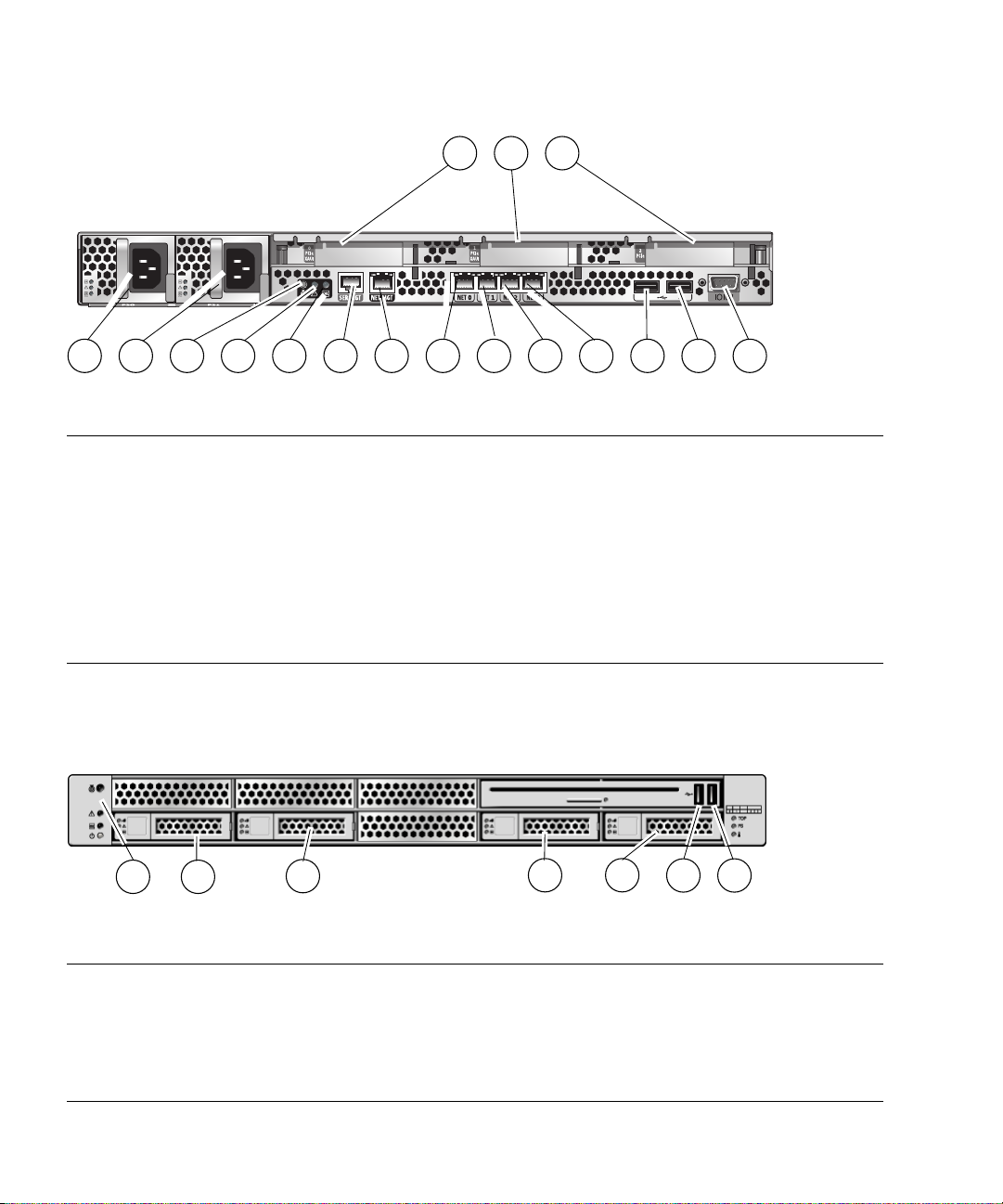
FIGURE 1-3 Rear Panel Cable Connectors and LEDs on the SPARC Enterprise T5140 Server
16 1715
1 2 43
Figure Legend
1 Power supply 0 10 Gbit Enet port NET2
2 Power supply 1 11 Gbit Enet port NET3
3 Locator LED button 12 USB por t 0
4 Service Required LED 13 USB por t 1
5 Power OK LED 14 TTYA serial port
6 Service processor serial management port 15 PCIe/XAUI slot 0
7 Service processor network management port 16 PCIe/XAUI slot 1
8 Gbit Enet port NET0 17 PCIe slot 2
9 Gbit Enet port NET1
5 6 7 8 9
10 11 12
USB ports 2 and 3 are located on the front panel (FIGURE 1-4).
FIGURE 1-4 Front Panel USB Ports on the SPARC Enterprise T5140 Server
1 2
3
4 5
13 14
6 7
Figure Legend
1 System status indicators: Top to bottom: Power button,
Power OK LED, Service Required LED, Locator LED
Button
2 Hard drive HDD0 6 USB port 2
3 Hard drive HDD1 7 USB port 3
4 Hard drive HDD2
5 Hard drive HDD3
8 SPARC Enterprise T5140 and T5240 Servers Installation Guide • February 2008
Page 35

See FIGURE 1-5 and FIGURE 1-6 for the locations of the ports on the SPARC Enterprise
T5240 server.
FIGURE 1-5 Rear Panel Cable Connectors and LEDs on the SPARC Enterprise T5240 Server
15
1 2 43
Figure Legend
1 Power supply 0 11 Gbit Enet port NET3
2 Power supply 1 12 USB por t 0
3 Locator LED button 13 USB por t 1
4 Service Required LED 14 TTYA serial port
5 Power OK LED 15 PCIe slot 3
6 Service processor serial management port 16 PCIe or XAUI slot 0
7 Service processor network management port 17 PCIe slot 4
8 Gbit Enet port NET0 18 PCIe or XAUI slot 1
9 Gbit Enet port NET1 19 PCIe slot 5
10 Gbit Enet port NET2 20 PCIe slot 2
16 17
18
5 6 7 8 9
19
10 11 12
20
13 14
USB ports 2 and 3 are located on the front panel (FIGURE 1-6).
Chapter 1 Preparing for Installation 9
Page 36

FIGURE 1-6 Front Panel USB Ports on the SPARC Enterprise T5240 Server
1 2
Figure Legend
1 System status indicators: Top to bottom: Power button,
Power OK LED, Service Required LED, Locator LED
Button
2 Hard drive HDD0 8 Hard drive HDD6
3 Hard drive HDD1 9 Hard drive HDD7
4 Hard drive HDD2 10 USB por t 2
5 Hard drive HDD3 11 USB por t 3
6 Hard drive HDD4
3 4
5 6
7 8
7 Hard drive HDD5
Slide Rail Assembly Notes for Both Servers
The rackmount kit has two slide rail assemblies. A slide rail assembly can be installed
on either the right or left side of the rack.
9
10
11
Note – The slide rail assemblies are different for the T5140 and T5240 servers. The
removable mounting bracket of the SPARC Enterprise T5140 rails slides 13 in. (33
cm) out of the slide rail, then locks in place. The removable mounting bracket of the
SPARC Enterprise T5240 rails slide 14 in. (35.5 cm) before locking.
Each slide rail assembly consists of a three-section slide rail and a removable
mounting bracket (
10 SPARC Enterprise T5140 and T5240 Servers Installation Guide • February 2008
FIGURE 1-7).
Page 37

FIGURE 1-7 Sections of the Slide Rail Assembly on the SPARC Enterprise T5240 Server
1
2
Figure Legend
1 Mounting bracket 3 Middle section
2 Front section 4 Rear section
■ The front, middle, and rear sections form the slide rail. The middle and rear sections
43
have holes for mounting screws, and adjust to fit rack depths from 24 in. (61 cm)
to 36.5 in. (93 cm). The front section can be extended to allow movement of the
server out of the rack.
■ The removable mounting bracket slides 14 in. (35.5 cm) out of the slide rail, then
locks in place. If you unlock the mounting bracket at this point, it slides an
additional 12 in. (30 cm) before separating from the slide rail. You can then mount
the mounting bracket to the right or left side of the server chassis.
■ Note that there are a total of five locks (FIGURE 1-8) in a slide rail assembly. Four
are on the mounting bracket. One lock is on the front section of the slide rail. The
installation procedure in Chapter 2 describes the uses of these locks.
Chapter 1 Preparing for Installation 11
Page 38

FIGURE 1-8 Locating the Locks on the Slide Rail Assembly for the SPARC Enterprise
T5240 Server
12 SPARC Enterprise T5140 and T5240 Servers Installation Guide • February 2008
Page 39
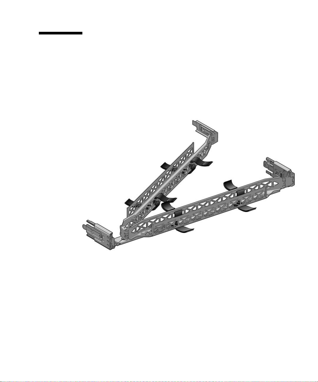
Cable Management Notes for Both Servers
The same cable management arm (CMA) is included with the rackmounting kit for
each server (
secure cabling to the CMA.
FIGURE 1-9 Cable Management Arm for Both Servers
FIGURE 1-9). The CMA clips onto the slide rails. Use the velcro straps to
Chapter 1 Preparing for Installation 13
Page 40
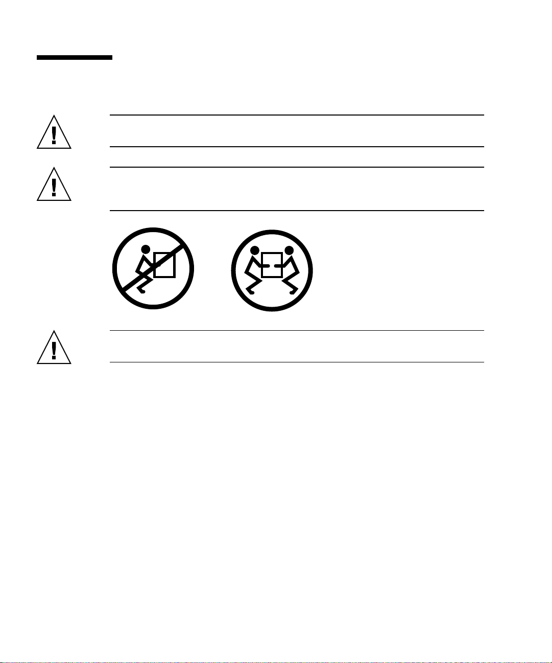
Safety Precautions
Caution – Deploy the antitilt bar on the equipment rack before beginning an
installation.
Caution – The SPARC Enterprise T5240 server weighs approximately 46 lb (20.7
kg). Two people are required to lift and mount this 2U server into a rack enclosure
when using the procedures in this document.
Caution – When completing a two-person procedure, always communicate your
intentions clearly before, during, and after each step to minimize confusion.
14 SPARC Enterprise T5140 and T5240 Servers Installation Guide • February 2008
Page 41

CHAPTER
2
Installing the SPARC Enterprise T5140 and T5240 Servers
This chapter provides instructions for installing the servers into an equipment rack.
Note – If your rackmount kit came with its own instructions, use the instructions in
your rackmount kit instead of the instructions in this chapter. After performing the
server installation, proceed to Chapter 3 for first-time power on.
This chapter contains the following sections:
■ “Installing the Servers in a Rack” on page 15
■ “Installing the Cable Management Arm for Both Servers” on page 24
■ “Connecting the Server Cables for Both Servers” on page 31
■ “Managing Cables With the CMA” on page 34
■ “Dismounting the Servers” on page 35
Note – References to left and right are from your viewpoint as you face either the
front or rear of the equipment.
Installing the Servers in a Rack
Note – Ensure that you have all of the parts in the rackmount kit before you begin
the installation of the server.
15
Page 42

Note – The procedures in this chapter are the same for both the 1U and 2U servers.
The illustrations show a 2U server only as an example.
The rackmount kit (same for both 1U and 2U servers) contains two slide rail
assemblies, which can be installed on either the right or left side of the rack. A slide
rail assembly consists of two parts: a slide rail and a removable mounting bracket.
The slide rail attaches to the rack posts. The mounting bracket attaches to the server
chassis. See “Slide Rail Assembly Notes for Both Servers” on page 10 for more
information about slide rail assemblies.
▼ To Install the Slide Rail Assemblies
1. Pull both mounting brackets completely out of their respective slide rails.
a. Simultaneously press and hold the upper and lower lock buttons of the
slide rail lock (
FIGURE 2-1 Unlocking the Slide Rail Assembly (Either Server)
FIGURE 2-1).
b. Pull the mounting bracket out until it locks in the extended position.
16 SPARC Enterprise T5140 and T5240 Servers Installation Guide • February 2008
Page 43
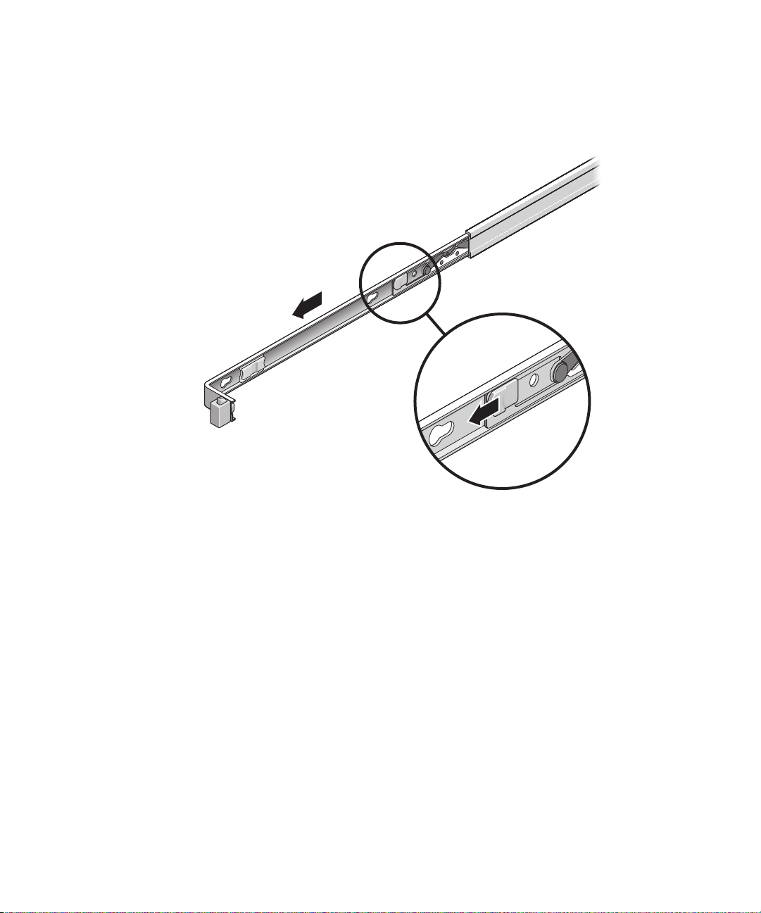
c. Slide the mounting bracket release button in the direction shown in
FIGURE 2-2, then slide the mounting bracket out of the slide rail.
FIGURE 2-2 Location of the Mounting Bracket Release Button (Either Server)
d. Press the metal lever (labeled Push) on the middle section (FIGURE 2-3)of
the sliding rail, then push the middle section back into the rack.
Chapter 2 Installing the SPARC Enterprise T5140 and T5240 Servers 17
Page 44

FIGURE 2-3 Unlocking the Slide Rail Middle Section (Either Server)
Metal lever
2. Attach a mounting bracket to the right side of the chassis.
a. Position the mounting bracket against the chassis (
the slide rail lock is at the front and the three keyed openings on the
mounting bracket are aligned with the three locating pins on the side of the
chassis.
18 SPARC Enterprise T5140 and T5240 Servers Installation Guide • February 2008
FIGURE 2-4). Ensure that
Page 45

FIGURE 2-4 Attaching a Mounting Bracket to the Chassis (Either Server)
b. Ensure that the heads of the locating pins protrude though the keyed
openings in the mounting bracket. Pull the mounting bracket toward the
front of the chassis until the bracket locks into place with an audible click.
c. Verify that all locating pins are trapped in the keyed openings and that the
correct locating pin has engaged the mounting bracket lock. See the right
side of
FIGURE 2-4.
3. Attach the second mounting bracket to the left side of the chassis.
4. Determine which rack hole numbers to use when attaching the slide rails to
the rack posts.
If the server is two rack units high (2U), the slide rails occupy the lower half of
the 2U space.
5. Determine which screws you will use to mount the slide rails.
■ If your rack has threaded mounting holes in the rack posts, determine
whether the threads are metric or standard. Select the appropriate screws
from the package included in the mounting kit.
Chapter 2 Installing the SPARC Enterprise T5140 and T5240 Servers 19
Page 46

■ If your rack does not have threaded mounting holes, the mounting screws are
secured with a caged nut.
6. Attach a slide rail to the right front rack post.
a. Loosely attach the front of a slide rail to the right front rack post using two
screws (
FIGURE 2-5).
Note – Do not tighten the screws yet.
FIGURE 2-5 Mounting a Slide Rail (Either Server)
b. Adjust the length of the slide rail by sliding the rear mounting flange to
reach the outside edge of the rear rack post.
c. Loosely attach the rear of the slide rail to the rear rack post with two
screws.
7. Attach the second slide rail to the left rack posts in a similar manner. Do not
tighten the screws.
20 SPARC Enterprise T5140 and T5240 Servers Installation Guide • February 2008
Page 47

8. Use the slide rail spacing tool to adjust the distance between the slide rails.
a. At the front of the rack, plug the left side of the tool into slots at the end of
the left rail (
FIGURE 2-6).
FIGURE 2-6 Using the Slide Rail Spacing Tool to Adjust the Distance Between the Slide
Rails (Either Server)
b. Insert the right side of the tool into the front end of the right rail.
c. Slide the end of the rail to the right or left as needed to allow the ends of
the tool to enter the ends of both rails.
The distance between the rails is now equal to the width of the server with
mounting brackets.
d. Tighten the screws to lock the ends of the rails in place.
e. At the rear of the rack, repeat Step a through Step d. for the rear ends of the
rails.
Chapter 2 Installing the SPARC Enterprise T5140 and T5240 Servers 21
Page 48
▼ To Insert and Lock the Server in the Rack
1. Deploy the antitilt bar, if the chassis or rack is so equipped.
Caution – The weight of the servers on extended slide rails can be enough to
overturn an equipment rack.
Caution – The 2U server weighs approximately 46 lb (20.7 kg). Two people are
required to lift and mount the server into a rack enclosure when using the
procedures in this chapter.
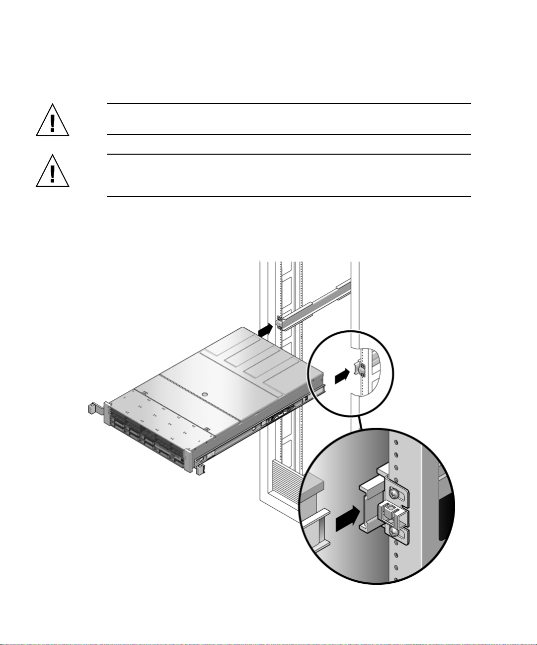
2. Insert the ends of the mounting brackets into the sliding rails (
FIGURE 2-7 Mounting the Chassis on the Slide Rails (Either Server)
FIGURE 2-7).
22 SPARC Enterprise T5140 and T5240 Servers Installation Guide • February 2008
Page 49

3. Slide the chassis into the rack.
Caution – Before continuing, verify that the server is securely mounted in the rack,
and that the slide rails are locked to the mounting brackets.
Installing the Cable Management Arm for Both Servers
The rackmounting kit for each server comes with the same cable management arm
(CMA) assembly. The CMA installation and cable management procedures are the
same for both servers. See “Cable Management Notes for Both Servers” on page 13
for more information on the cable management arm.
Note – The CMA includes velcro straps to secure the cables inside the CMA. Do not
install the velcro straps until you install the CMA, connect the cables, and place the
cabling inside the CMA as described in the following procedures.
▼ To Install the Cable Management Arm
Caution – Support the CMA during this installation. Do not allow the assembly to
hang by its own weight until it is secured by all three attachment points.
1. Remove the tape from the CMA rail extension (on the left of the CMA) and
remove the CMA rail extension.
2. Attach the CMA rail extension to rear left slide rail (
At the rear of the rack, plug the CMA rail extension into the end of the left
sliding rail assembly. The tab at the front of the rail extension clicks into place.
Chapter 2 Installing the SPARC Enterprise T5140 and T5240 Servers 23
FIGURE 2-8).
Page 50
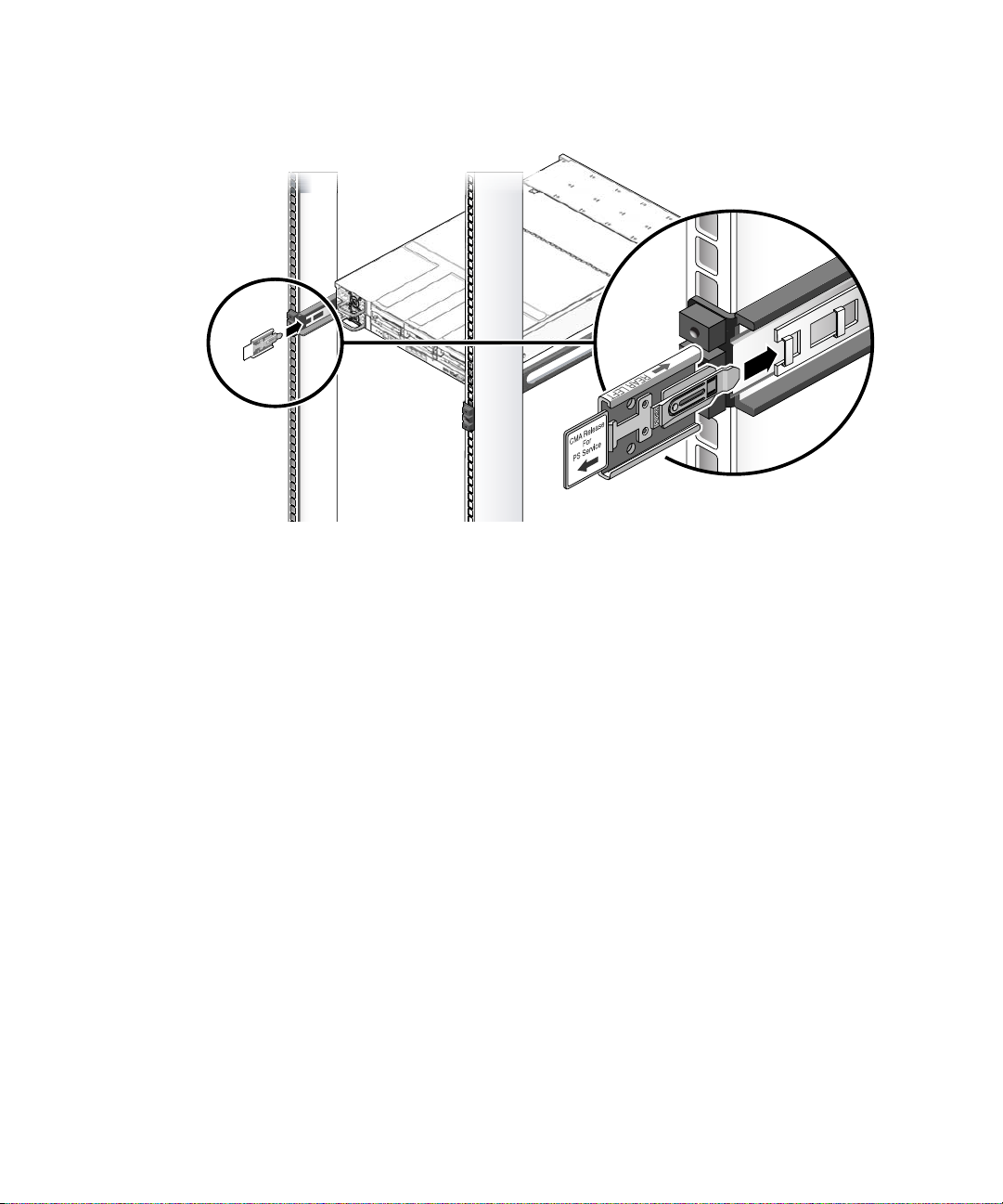
FIGURE 2-8 Inserting the CMA Rail Extension Into the Rear of the Left Slide Rail (Either
Server)
The right sides of the two CMA arms have hinged extensions. On the
manufacturer’s instruction sheet, the smaller extension is called the CMA
Connector for Inner Member. This extension attaches to the right mounting
bracket. The larger extension is called the CMA Connector for Outer Member,
and attaches to the right sliding rail.
24 SPARC Enterprise T5140 and T5240 Servers Installation Guide • February 2008
Page 51

3. Insert the smaller extension into the clip located at the end of the mounting
bracket (
FIGURE 2-9).
Slide the smaller extension into the square hole on the middle-in-width of the
clip that is located at the end of the mounting bracket.
FIGURE 2-9 Mounting the Inner CMA Connector (Either Server)
Chapter 2 Installing the SPARC Enterprise T5140 and T5240 Servers 25
Page 52

4. Insert the larger extension into the end of the right sliding rail (FIGURE 2-10).
FIGURE 2-10 Attaching the Outer CMA Connector (Either Server)
26 SPARC Enterprise T5140 and T5240 Servers Installation Guide • February 2008
Page 53

5. Insert the hinged plastic connector at the left side of the CMA fully into the
CMA rail extension (
FIGURE 2-11).
The plastic tab on the CMA rail extension locks the hinged plastic connector in
place.
FIGURE 2-11 Mounting the Left Side of the Slide Rail (Either Server)
Chapter 2 Installing the SPARC Enterprise T5140 and T5240 Servers 27
Page 54

▼ To Verify the Operation of the Slide Rails and
the CMA
Tip – Two people are needed for this procedure, one to move the server in and out
of the rack, and one to observe the cables and CMA.
1. For a free-standing rack, deploy the antitilt bar.
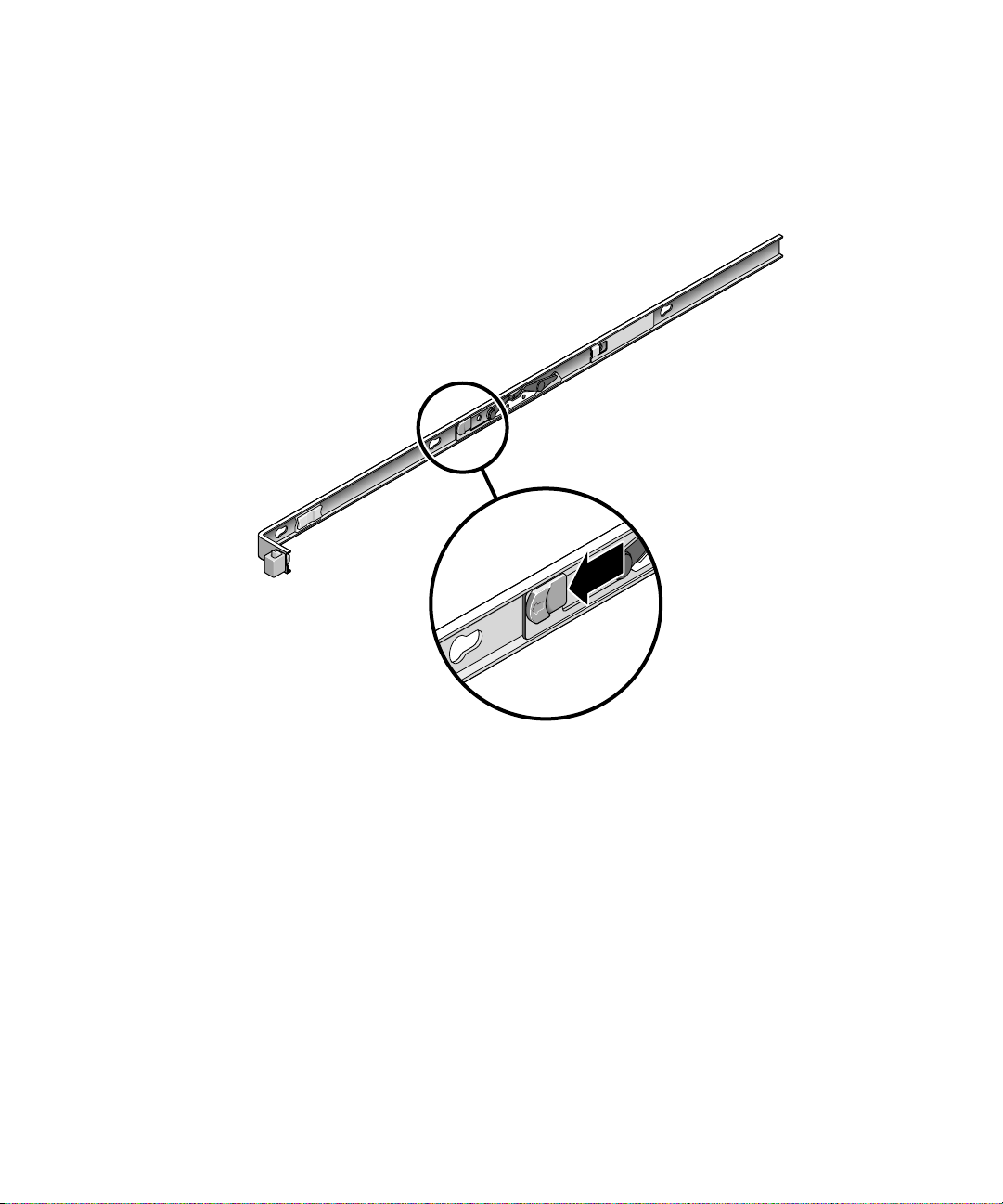
2. Unlock the slide lock buttons (
chassis.
3. Slowly pull the server out of the rack until the slide rails reach their stops.
FIGURE 2-12 Unlocking the Slide Rail Assembly (Either Server)
FIGURE 2-12) at the right and left sides of the
4. Inspect any attached cables for binding or kinks.
5. Verify that the CMA extends fully and does not bind in the slide rails.
6. Verify that the server extends fully and locks in the maintenance position.
The server should stop after approximately 15 inches (40 cm) of travel.
28 SPARC Enterprise T5140 and T5240 Servers Installation Guide • February 2008
Page 55
7. Pull both slide rail release buttons toward you simultaneously and slide the
server back into the rack (
FIGURE 2-13).
The server should slide smoothly into the rack without binding.
FIGURE 2-13 Rail Mounting Bracket Release Button (Either Server)
8. Verify that the CMA retracted without binding.
9. Adjust the cable straps and CMA as required to secure the cables.
See “Managing Cables With the CMA” on page 34.
Chapter 2 Installing the SPARC Enterprise T5140 and T5240 Servers 29
Page 56

Connecting the Server Cables for Both Servers
To boot the server, you must connect and configure the network and serial ports. The
procedures are given in the following sections.
■ “To Connect the Service Processor Serial Management Port” on page 31
■ “To Connect the Service Processor Network Management Port” on page 32
■ “To Connect the Ethernet Network Cables” on page 33
■ “To Connect the AC Power Cable to the Server” on page 34
The servers also have serial and USB ports available for connections to optional
devices. See “Port, Connector, and LED Locations for Both Servers” on page 7 for
more information.
Note – When you are finished connecting the cables to the server, ensure that the
server can slide smoothly in and out of the rack without binding or damaging the
cables. See the section, “To Verify the Operation of the Slide Rails and the CMA” on
page 29.
▼ To Connect the Service Processor Serial
Management Port
The service processor serial management port is marked SER MGT (FIGURE 2-14).
This port is the farthest left RJ-45 port on the rear panel.
Note – The cable and DB-9 RJ-45 adapters are for the host serial port, and not for
the server SER MGT port.
FIGURE 2-14 Service Processor Serial Management Port – Rear Panel
30 SPARC Enterprise T5140 and T5240 Servers Installation Guide • February 2008
Page 57

Use this port for server management. This port is needed to set up the service
processor network management port, as detailed in “Enabling the Service Processor
Network Management Port” on page 44.
Note – Use the service processor serial management port only for server
management. It is the default connection between the service processor and a
terminal or a computer.
Caution – Do not attach a modem to this port.
● Connect a Category 5 cable from the SER MGT serial management port to the
terminal device.
When connecting either a DB-9 or a DB-25 cable, use an adapter to perform the
crossovers given for each connector.
▼ To Connect the Service Processor Network
Management Port
The service processor network management port is labeled NET MGT (FIGURE 2-15).
This port is located just to the right of the serial management (SER MGT) port on the
rear panel.
FIGURE 2-15 Service Processor Network Management Port – Rear Panel
Note – This port is not operational until you configure the network settings
(through the serial management port), as detailed in “To Configure the Service
Processor Network Management Port” on page 47.
Note – If you have access to a DHCP server on the network, you can see the service
processor get an IP address because the DHCP client is enabled by default.
Chapter 2 Installing the SPARC Enterprise T5140 and T5240 Servers 31
Page 58
Note – The service processor network management port is configured by default to
retrieve network settings with Dynamic Host Configuration Protocol (DHCP) and
allow connections using Solaris Secure Shell (SSH). You might need to modify these
settings for your network. Instructions are given in Chapter 3.
● Connect a Category 5 cable from the NET MGT network management port to
your network switch or hub.
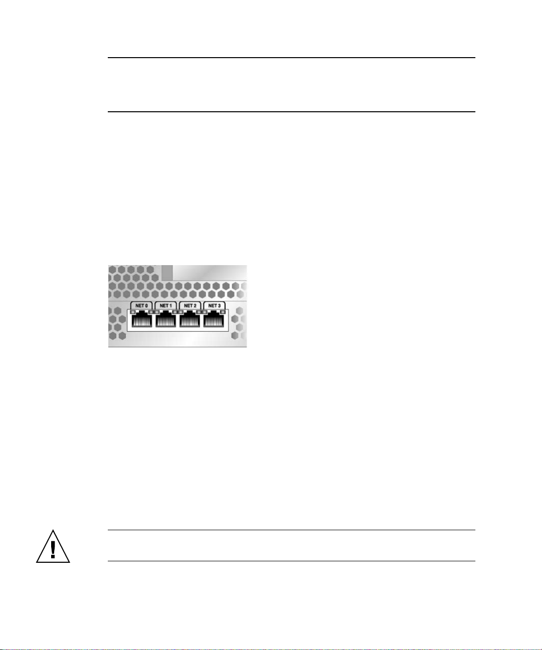
▼ To Connect the Ethernet Network Cables
The server has four network connectors, marked NET0, NET1, NET2, and NET3
(
FIGURE 2-16). These connectors are RJ-45 Gigabit Ethernet.
FIGURE 2-16 Service Processor Ethernet Network Ports – Rear Panel
1. Connect a Category 5 cable from your network switch or hub to Ethernet Port 0
(NET0) on the rear of the chassis.
NET0 is the farthest left port in the 4-port network cluster in
2. Connect Category 5 cables from your network switch or hub to the remaining
Ethernet ports (NET1, NET2, NET3), as needed.
▼ To Connect the AC Power Cable to the Server
Powering on the system for the first time requires special preparation and
procedures. For example, if you have not prepared a display before connecting the
AC power cable, system messages might be lost.
Caution – Finish the hardware procedures in this chapter, but do not attach the AC
power cable yet.
32 SPARC Enterprise T5140 and T5240 Servers Installation Guide • February 2008
FIGURE 2-16.
Page 59
Powering on the system for the first time requires special preparation and
procedures. For example, if you have not prepared a display before connecting the
AC power cable, system messages could be lost.
Caution – The server goes into Standby mode and the service processor initializes
as soon as the AC power cable is connected to the power source.
● Go to “Powering On the System for the First Time” on page 37 for instructions
on connecting the server to AC power.
Managing Cables With the CMA
Managing the cables with the CMA is the same for both servers.
▼ Securing the Server Cables in the CMA
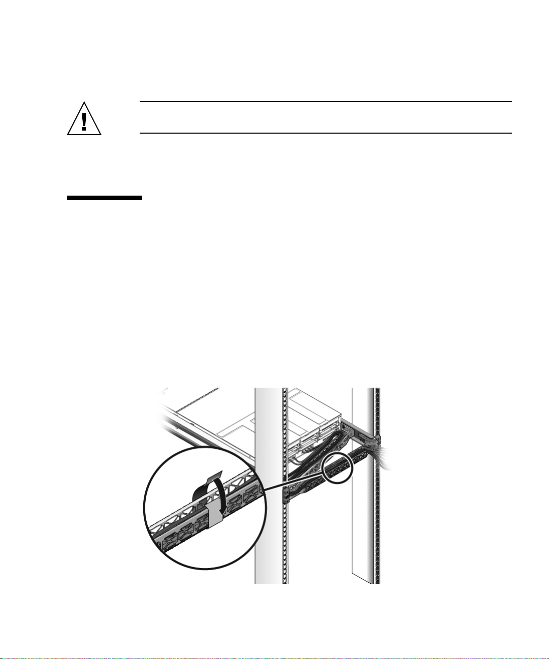
● Once the server cables are connected and placed inside the CMA, open the
velcro cable straps and wrap the straps around the CMA securing the cables
inside the CMA. (
FIGURE 2-17).
FIGURE 2-17 Securing the Server Cables With the CMA and Velcro Straps (Either Server)
Chapter 2 Installing the SPARC Enterprise T5140 and T5240 Servers 33
Page 60

Caution – Verify the operation of the slide rails and CMA, and cable service loops.
Perform the steps in the following procedure again before continuing: “To Verify the
Operation of the Slide Rails and the CMA” on page 29.
Dismounting the Servers
To install or replace internal parts in the server, you must first remove the server
from the rack. For the removal procedure, refer to the SPARC Enterprise T5140 and
T5240 Servers Service Manual.
34 SPARC Enterprise T5140 and T5240 Servers Installation Guide • February 2008
Page 61

Chapter 2 Installing the SPARC Enterprise T5140 and T5240 Servers 35
Page 62

36 SPARC Enterprise T5140 and T5240 Servers Installation Guide • February 2008
Page 63

CHAPTER
3
Powering On the System
This chapter includes instructions for booting the servers and for enabling the
service processor network management port.
This chapter contains the following topics:
■ “Powering On the System for the First Time” on page 37
■ “Enabling the Service Processor Network Management Port” on page 44
■ “Logging Into the Service Processor” on page 45
■ “Using the Service Processor for Common Operations” on page 50
■ “Booting the Solaris Operating System” on page 56
■ “Verifying System Functionality” on page 59
Powering On the System for the First Time
This section provides an overview and instructions for powering on your system the
first time.
ILOM System Console
When you power on the system, the boot process begins under the control of the
Integrated Lights Out Manager (ILOM) system console. The system console displays
status and error messages generated by firmware-based tests during system startup.
37
Page 64

Note – To see these status and error messages, connect a terminal or terminal
emulator to the serial management port (SER MGT). For a basic procedure to
connect a terminal or terminal emulator, see “To Power On the System for the First
Time” on page 38.
For a more detailed discussion on configuring the system console and connecting
terminals, refer to the SPARC Enterprise T5140 and T5240 Servers Administration Guide.
ILOM Service Processor
After the system console finishes its low-level system diagnostics, the ILOM service
processor initializes and runs a higher level of diagnostics. When you access the
ILOM service processor using a device connected to the serial management port, you
see the output of the ILOM diagnostics.
By default, the service processor configures the network management port
automatically, retrieving network configuration settings using the Dynamic Host
Configuration Protocol (DHCP) and allowing connections using Secure Shell (SSH).
Note – If you are unable to use DHCP on your network, you must connect to the
ILOM service processor using the serial management port to configure the network
management port for your network. See “To Configure the Service Processor
Network Management Port” on page 47.
▼ To Power On the System for the First Time
1. Confirm that you have completed all of the preparations for installation.
See the instructions in Chapter 1.
2. Confirm that you have completed the installation of the server in its rack.
See the instructions in Chapter 2.
3. Connect a terminal or a terminal emulator (PC or workstation) to the service
processor serial management port.
Configure the terminal or terminal emulator with these settings:
■ 9600 baud
■ 8 bits
■ No parity
■ 1 Stop bit
38 SPARC Enterprise T5140 and T5240 Servers Installation Guide • February 2008
Page 65

■ No handshake
A null modem configuration is needed, meaning the transmit and receive signals are
reversed (crossed over) for DTE to DTE communications. You can use the supplied
RJ-45 crossover adapters with a standard RJ-45 cable to achieve the null modem
configuration.
Note – When you power on the server for the first time and you do not have a
terminal or terminal emulator (PC or workstation) connected to the service processor
serial management port, you will not see system messages.
Chapter 3 Powering On the System 39
Page 66
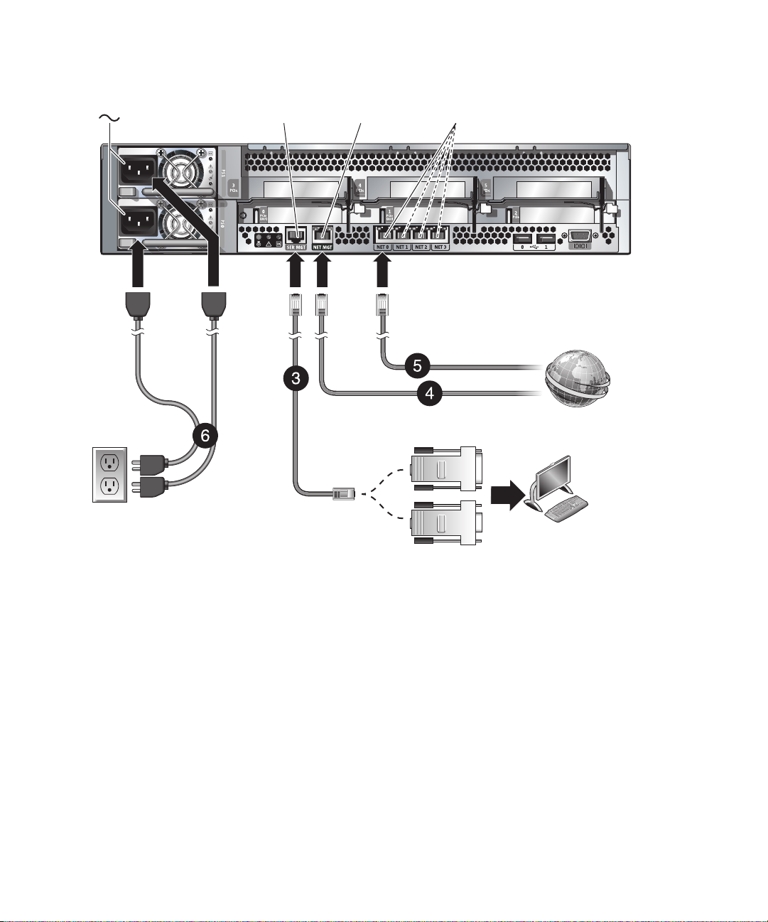
FIGURE 3-1 Server Connections
SER MGT
RJ-45
NET MGT
RJ-45
RJ-45 to DB-25
crossover
adapter
NET 0 to NET 3
RJ-45
Host to Ethernet
SP to Ethernet
RJ-45 to DB-9
crossover
adapter
4. (Optional) Connect an Ethernet cable between the server’s Net MGT port
(
FIGURE 3-1) and the network to which future connections to the SP and host
will be made.
After the initial configuration of the system using the SP SER MGT port,
communication with the SP and host is usually performed through this Ethernet
interface.
5. Connect an Ethernet cable between one of the server’s NET ports (
and the network to which the server will communicate.
6. Plug the power cords into the power supplies and into a power source.
40 SPARC Enterprise T5140 and T5240 Servers Installation Guide • February 2008
Terminal
device
FIGURE 3-1)
Page 67

Note – Only one power connection is required for operation. Use two power
connections for redundancy.
The service processor runs on the 3.3V standby voltage. As soon as AC power is
connected to the system, the service processor powers on, runs diagnostics, and
initializes the ILOM firmware.
After a few minutes, the SP login prompt appears on the terminal device. The
host is not initialized or powered on yet.
7. At the terminal device, log in to the SP as root with a password of changeme.
XXXXXXXXXXXXXXXX login: root
Password: changeme
. . .
->
After a brief delay, the SP prompt is displayed (->). At this point, there are many
commands you can perform using the Integrated Lights Out Manager interface.
Additional SP information, such as how to change the password and how to set
up the SP network parameters is available in the online documentation set.
8. Power on the server and redirect the host output to display on the serial
terminal device:
-> start /SYS
Are you sure you want to start /SYS (y/n)? y
-> start /SP/console
Are you sure you want to start /SP/CONSOLE (y/n)? y
Serial console started. To stop, type #.
. . .
After you start the SP console, the server initialization takes approximately 20
minutes to complete.
Chapter 3 Powering On the System 41
Page 68

9. When prompted, follow the onscreen instructions for configuring the Solaris
Operating System on your host and enter the following configuration
information.
You will be prompted to confirm the configuration several times, enabling
confirmation and changes. If you are not sure how to respond to a particular
value, you can accept the default, and make future changes when the Solaris OS
is running.
Parameter Description
Language Select a number from the displayed language list.
Locale Select a number from the displayed locale list.
Terminal Type Select a terminal type that corresponds with your terminal device.
Network? Select Yes.
Multiple Network
Interfaces
DHCP? Select Yes or No according to your network environment.
Host Name Enter the host name for the server.
IP Address Enter the IP address for this Ethernet interface.
Subnet? Select Yes or No according to your network environment.
Subnet Netmask (If subnet was Yes) Enter the netmask for the subnet for your network
IPv6? Specify whether or not to use IPv6. If you are not sure, select No to configure the
Security Policy Select either standard UNIX security (No) or Kerberos Security (Yes). If you are
Confirm Review the onscreen information and change it if needed. Otherwise, continue.
Name Service Select the name service according to your network environment.
NFSv4 Domain Name Select the type of domain name configuration according to your environment. If
Time Zone (Continent) Select your continent.
Time Zone (Country or
Region)
Select the network interfaces that you plan to configure. If you are not sure, select
the first one in the list.
environment.
Ethernet interface for IPv4.
not sure, select No.
Note–If you select a name service other than None, you will be prompted for
additional name service configuration information.
you are not sure, select Use the NFSv4 domain derived by the system.
Select your country or region.
42 SPARC Enterprise T5140 and T5240 Servers Installation Guide • February 2008
Page 69

Time Zone Select the time zone.
Date and Time Accept the default date and time or change the values.
root Password Enter the root password twice. This password is for the superuser account for
the Solaris OS on this server. This password is not the SP password.
10. Log in to the server and explore its capabilities.
There are many commands you can use to verify the functionality of the system.
The following list describes a few of them:
■ showrev – Displays the hostname and system architecture information. Use
the -a option with this command to see the patches that are installed.
■ psrinfo – Displays information about the number and status of the
processors and cores in the host.
■ prtdiag – Displays system configuration and diagnostic information.
Review the Solaris OS man pages and documentation for more details.
Chapter 3 Powering On the System 43
Page 70

Enabling the Service Processor Network Management Port
The service processor network management port is not operational unless your
network employs DHCP, in which case the configuration in automatic. If you
network uses DHCP, you can run this command
-> show /SP/network
to view your server’s network configuration information. For example,
-> show /SP/network
/SP/network
Targets:
Properties:
commitpending = (Cannot show property)
dhcp_server_ip = 10.8.31.5
ipaddress = 10.8.31.188
ipdiscovery = dhcp
ipgateway = 10.8.31.248
ipnetmask = 255.255.252.0
macaddress = 00:14:4F:7E:83:4F
pendingipaddress = 10.8.31.188
pendingipdiscovery = dhcp
pendingipgateway = 10.8.31.248
pendingipnetmask = 255.255.252.0
state = enabled
Commands:
cd
set
show
If your network does not use DHCP, the network management port is not
operational until you configure network settings for the service processor. Configure
the service processor in this order:
1. After the service processor boots, access the ILOM CLI through the serial
management port. See “To Log Into the Service Processor Using the Serial
Management Port” on page 45.
44 SPARC Enterprise T5140 and T5240 Servers Installation Guide • February 2008
Page 71

2. Configure the service processor. See “To Configure the Service Processor Network
Management Port” on page 47.
3. Commit the changes to the service processor parameters. See Step 5 in “To
Configure the Service Processor Network Management Port” on page 47.
You can now use the network management port at any time to access the service
processor. See “To Log Into the Service Processor Using the Network Management
Port” on page 50.
Logging Into the Service Processor
If you are powering on the system for the first time after installation, use the service
processor serial port to power on the system and run POST. See “To Log Into the
Service Processor Using the Serial Management Port” on page 45.
If the network management port has already been configured, you can use it instead
of the serial management port. See “To Log Into the Service Processor Using the
Network Management Port” on page 50.
▼ To Log Into the Service Processor Using the
Serial Management Port
After the service processor boots, access the ILOM CLI to configure and manage the
system. The ILOM CLI prompt (->) is displayed at the first time the service
processor is booted. The default configuration provides an ILOM CLI root user
account. The default root password is changeme. Change the password using the
service processor ILOM CLI password command.
Chapter 3 Powering On the System 45
Page 72

1. If this is the first time the system has been powered on, use the password
command to change the root password.
...
Starting OpenBSD Secure Shell server: sshd.
Starting Servicetags listener: stlistener.
Starting FRU update program: frutool.
hostname login: root
Password: changeme
Copyright 2007 Sun Microsystems, Inc. All rights reserved.
Use is subject to license terms.
...
Federal Acquisitions: Commercial Software -- Government Users
Subject to Standard License Terms and Conditions.
...
Warning: password is set to factory default.
-> set /SP/users/root password
Enter new password: ********
Enter new password again: ********
->
Note – After the root password has been set, on subsequent reboots, the ILOM CLI
login prompt is displayed.
2. Enter root for the login name followed by your password.
...
hostname login: root
Password: password (nothing displayed)
Waiting for daemons to initialize...
Daemons ready
Integrated Lights Out Manager
Version 2.0.0.0
Copyright 2007 Sun Microsystems, Inc. All rights reserved.
Use is subject to license terms.
->
46 SPARC Enterprise T5140 and T5240 Servers Installation Guide • February 2008
Page 73

▼ To Configure the Service Processor Network
Management Port
Note – If your network allows the use of DHCP, this configuration is performed
automatically the first time you boot the system.
Use this procedure only when:
■ You are unable to use DHCP on your network.
■ You need to modify the ILOM service processor network management port
settings.
In this procedure, you connect to the ILOM service processor using the serial
management port to manually reconfigure the network management port.
Note – For more information on configuring ILOM, refer to the Integrated Lights Out
Manager 2.0 Supplement for SPARC Enterprise T5140 and T5240 Servers.
Set these network parameters according to the specific details of your network
configuration:
■ /SP/network state – Specifies whether the service processor is on the network
or not
■ /SP/network pendingipaddress – IP address of the service processor
■ /SP/network pendingipgateway – IP address of the gateway for the subnet
■ /SP/network pendingipnetmask – Netmask for the service processor subnet
■ /SP/network pindingipdiscovery - Specifies whether the service processor
uses DHCP or static IP address assignment
■ /SP/network commitpending - Commits the service processor to use the
pending settings
Configure these parameters with the set command. The usage is as follows:
set target property=value where /SP/network is the target and
pendingipaddress=xxx.xxx.xxx.xxx, for example, is the property=value.
3. Configure the service processor using information from your network
administrator.
Your choices are
■ dhcp - Set up the network connection with a dynamically created IP
configuration.
■ static - Set up the network connection with a static IP configuration.
Chapter 3 Powering On the System 47
Page 74

a. If you choose to use a dynamically created IP address (use DHCP to retrieve
the network setting), set pendingipdiscovery to dhcp.
-> set /SP/network pendingipdiscovery=dhcp
Set 'pendingipdiscovery' to 'dhcp'
a. If you choose to configure a static IP configuration. set the parameters
pendingipdiscovery, pendingipaddress, pendingipgateway, and
pendingipnetmask as follows.
i. Set the service processor to accept a static IP address.
-> set /SP/network pendingipdiscovery=static
Set 'pendingipdiscovery' to 'static'
ii. Set the IP address for the service processor.
-> set /SP/network pendingipaddress=service-processor-IPaddr
Set 'pendingipaddress' to 'service-processor-IPaddr'
iii. Set the IP address for the service processor gateway.
-> set /SP/network pendingipgateway=gateway-IPaddr
Set 'pendingipgateway' to 'gateway-IPaddr'
iv. Set the netmask for the service processor.
-> set /SP/network pendingipnetmask=255.255.255.0
Set 'pendingipnetmask' to '255.255.255.0'
This example uses 255.255.255.0 to set the netmask. Your network
environment subnet might require a different netmask. Use a netmask number
most appropriate to your environment.
4. Use the show /SP/network command to verify that the parameters were set
correctly.
CODE EXAMPLE 3-1 shows parameters that have been set to convert a service
processor from a dhcp configuration to a static configuration
CODE EXAMPLE 3-1 show /SP/network Command Output
-> show /SP/network
/SP/network
Targets:
48 SPARC Enterprise T5140 and T5240 Servers Installation Guide • February 2008
Page 75

CODE EXAMPLE 3-1 show /SP/network Command Output
Properties:
commitpending = (Cannot show property)
dhcp_server_ip = xxx.xxx.xxx.xxx
ipaddress = xxx.xxx.xxx.xxx
ipdiscovery = dhcp
ipgateway = xxx.xxx.xxx.xxx
ipnetmask = 255.255.252.0
macaddress = 00:14:4F:3F:8C:AF
pendingipaddress = xxx.xxx.xxx.xxx
pendingipdiscovery = static
pendingipgateway = xxx.xxx.xxx.xxx
pendingipnetmask = 255.255.255.0
state = enabled
Commands:
cd
set
show
->
Note – After setting the configuration parameters, you must enter the set
/SP/network commitpending=true command for the new values to take affect.
5. Commit the changes to the service processor network parameters.
-> set /SP/network commitpending=true
Set 'commitpending' to 'true'
Note – You can run the show /SP/network command again (after performing the
set /SP/network commitpending=true command) to verify that the
parameters have been updated.
Chapter 3 Powering On the System 49
Page 76

▼ To Log Into the Service Processor Using the
Network Management Port
Note – You must configure the service processor parameters shown in “To
Configure the Service Processor Network Management Port” on page 47 before you
can use the network management port.
● Open an SSH session and connect to the service processor by specifying its
network address.
% ssh root@xx.xxx.xx.x
...
Are you sure you want to continue connecting (yes/no)? yes
...
Password: password (nothing displayed)
Waiting for daemons to initialize...
Daemons ready
Integrated Lights Out Manager
Version 2.0.0.0
Copyright 2007 Sun Microsystems, Inc. All rights reserved.
Use is subject to license terms.
->
Using the Service Processor for Common Operations
Note – For more information on using the ILOM service processor, refer to the
Integrated Lights Out Manager 2.0 Supplement for SPARC Enterprise T5140 and T5240
Servers.
50 SPARC Enterprise T5140 and T5240 Servers Installation Guide • February 2008
Page 77

▼ To Power On the System
1. Perform the following steps to verify that there are no faults:
a. Set the virtual keyswitch to diag mode so that POST will run in Service
mode.
-> set /SYS keyswitch_state=diag
Set ’keyswitch_state’ to ’diag’
b. To initiate the power on sequence, type the start /SYS command.
You will see an ILOM CLI alert message on the system console. This message
indicates that the system has reset.
-> start /SYS
Are you sure you want to start /SYS (y/n)? y
Starting /SYS
->
Chapter 3 Powering On the System 51
Page 78

c. Switch to the system console to view POST output.
-> start /SP/console
Are you sure you want to start /SP/console (y/n)? y
Serial console started. To stop, type #.
.
.
.
Watch the POST output for possible fault messages. The following output is a
sign that POST did not detect any faults:
.
.
.
2007-12-14 16:34:53.385 0:1:0>INFO:
2007-12-14 16:34:53.391 0:1:0> POST Passed all devices.
2007-12-14 16:34:53.399 0:1:0>POST: Return to VBSC.
2007-12-14 16:34:53.406 0:1:0>Master set ACK for vbsc runpost
command and spin.
...
SPARC Enterprise T5240, No Keyboard
Copyright 2007 Sun Microsystems, Inc. All rights reserved.
OpenBoot 4.27.x, 3968 MB memory available, Serial #74409918.
Ethernet address 0:14:4f:6f:67:be, Host ID: 846f67be.
{8} ok
2. Type the console escape sequence (by default #. (Hash-Period)) to return to
the ILOM prompt.
3. Check the POST execution result with the following command:
-> show /SP/faultmgmt -level all
Note – Depending on the configuration of ILOM, POST variables, and whether
POST detected faults or not, the server might boot, or the system might remain at
the ok prompt. If the system is at the ok prompt, type boot.
52 SPARC Enterprise T5140 and T5240 Servers Installation Guide • February 2008
Page 79

4. Use the set /SYS keyswitch_state=normal command to return the virtual
keyswitch to Normal mode (default) so that the system can power on and start
the boot process.
-> set /SYS keyswitch_state=normal
Set ’keyswitch_state’ to ’normal’
▼ To Connect to the System Console
Output from POST, OpenBoot, and the Solaris OS is displayed in the system console
using the network console on the service processor.
● Type the start /SP/console command.
Multiple users can be connected to the console, but only one can be attached.
-> start /SP/console
Are you sure you want to start /SP/console (y/n)? y
Serial console started. To stop, type #.
Note – For more information about POST output, refer to the SPARC Enterprise
T5140 and T5240 Servers Service Manual.
▼ To Perform a Normal System Initialization
1. Issue the start /SYS command .
-> start /SYS
Are you sure you want to start /SYS (y/n)? y
Starting /SYS
2. To initiate the power on sequence, type the start /SYS command.
You will see an ILOM CLI alert message on the system console. This message
indicates that the system has reset..
-> start /SP/console
Are you sure you want to start /SP/console (y/n)? y
Serial console started. To stop, type #.
Chapter 3 Powering On the System 53
Page 80

The CPU and memory controllers initialize, and eventually OpenBoot initializes.
After a number of system console messages, the ok prompt appears, or the system
will boot into the Solaris OS.
Note – System behavior depends on how the auto-boot variable is set. See the
SPARC Enterprise T5140 and T5240 Servers Service Manual for more information.
The following example output is a small section of the complete output.
0:1:0>
0:1:0>SPARC-Enterprise[TM] T5140/T5240 POST 4.27.x.
2007/12/11 18:55
...
0:1:0>Network Interface Unit Tests....Done
0:1:0>Functional CPU Tests....Done
0:1:0>Extended Memory Tests....Done
2007-12-14 16:45:28.800 0:1:0>INFO:
2007-12-14 16:45:28.806 0:1:0> POST Passed all devices.
2007-12-14 16:45:28.816 0:1:0>POST: Return to VBSC.
2007-12-14 16:45:28.824 0:1:0>Master set ACK for vbsc runpost
command and spin...
SPARC Enterprise T5240, No Keyboard
Copyright 2007 Sun Microsystems, Inc. All rights reserved.
OpenBoot 4.27.x, 3968 MB memory available, Serial #74409918.
Ethernet address 0:14:4f:6f:67:be, Host ID: 846f67be.
{0} ok
Devices in the OpenBoot Device Tree
TABLE 3-1 Disk Slot Numbers, Logical Device Names, and Physical Device Names
Disk Slot Number Logical Device Name
Slot 0 c0t0d0 /devices/pci@0/pci@0/pci@2/scsi@0/sd@0,0
54 SPARC Enterprise T5140 and T5240 Servers Installation Guide • February 2008
*
Physical Device Name
Page 81

TABLE 3-1 Disk Slot Numbers, Logical Device Names, and Physical Device Names (Continued)
Disk Slot Number Logical Device Name
Slot 1 c0t1d0 /devices/pci@0/pci@0/pci@2/scsi@0/sd@1,0
Slot 2 c0t2d0 /devices/pci@0/pci@0/pci@2/scsi@0/sd@2,0
Slot 3 c0t3d0 /devices/pci@0/pci@0/pci@2/scsi@0/sd@3,0
* The logical device names might appear differently on your system, depending on the number and type of add-on disk controllers
installed.
TABLE 3-2
Device Identifiers Devices
/SYS/MB/CMPcpu_number/Pstrand_number CMP (0-1) CPU strand (0-63)
/SYS/MB/CMPn/RISERn/PCIEslot_number CMP (0-1) Riser (0-1) PCIe
/SYS/MB/CMPn/RISERn/XAUIcard_number CMP (0-1) Riser (0-1) XAUI
/SYS/MB/NETnetwork_number Network interfaces (0-3)
/SYS/MB/PCIE PCIe root complex
/SYS/MB/USBnumber USB ports (0-1, located on
/SYS/MB/CMPn/L2_BANKnumber CMP (0-1) Bank (0-7)
/SYS/DVD DVD
/SYS/USBBD/USBnumber USB ports (2-3, located on
/SYS/TTYA DB9 Serial Port
/SYS/MB/CMPn/MRn/BR/branch_number/CHchannel_number/Ddimm_number CMP (0-1) Riser (0-1) Branch
Device Identifiers and Devices
*
Physical Device Name
slot (0-5)
card (0-1)
rear of chassis)
front of chassis)
(0-1) Channel (0-1) DIMM
(0-3)
Booting the Solaris Operating System
The Solaris OS is preinstalled on the servers on the disk in slot 0. The Solaris OS is
not configured (that is, the sys-unconfig command was run in the factory). If you
boot the system from this disk, you will be prompted to configure the Solaris OS for
your environment.
Chapter 3 Powering On the System 55
Page 82

▼ To Boot the Solaris Operating System
1. At the ok prompt, boot from the disk that contains the Solaris OS.
■ If you know which disk to boot from, skip this step and perform Step 2.
■ If you need to determine which disk to boot from, issue the show-disks
command at the ok prompt to see the path to the configured disks, similar to the
following:
ok show-disks
a) /pci@0/pci@0/pci@2/scsi@0/disk
b) /pci@0/pci@0/pci@1/pci@0/pci@1/pci@0/usb@0,2/storage@2/disk
q) NO SELECTION Enter Selection, q to quit: q
ok
2. Type the boot command at the ok prompt.
Use the value from Step 1 to construct the boot command. You must append the
target to the disk path.
In the following example, the server is booted from disk 0 (zero) on a SPARC
Enterprise T5140 server.
ok boot disk0
Boot device: /pci@0/pci@0/pci@2/scsi@0/disk@0 File and args:
SunOS Release 5.10 Version Generic_127127-03 64-bit
Copyright 1983-2007 Sun Microsystems, Inc. All rights reserved.
Use is subject to license terms.
Hostname: hostname
NIS domain name is x.x.x.x
hostname console login:
▼ To Avoid Booting the Solaris Operating System
at Start Up
In hard drive HDD0, the Solaris OS is preinstalled.
● If you do not want to start the preinstalled OS, set the Open Boot PROM
parameter auto-boot? to false. For example:
-> set /HOST/bootmode script="setenv auto-boot? false"
56 SPARC Enterprise T5140 and T5240 Servers Installation Guide • February 2008
Page 83

▼ To Reset the System
● If it is necessary to reset the system, use the shutdown -g0 -i6 -y
command.
# shutdown -g0 -i6 -y
It is not necessary to power the system off and on to simply reset the system.
▼ To Power Cycle the System
If a simple reset does not clear a system problem, you can power the system off and
on with this procedure.
1. Shut down the Solaris OS.
At the Solaris OS prompt, type the shutdown -g0 -i0 -y command. Then
type h when prompted to halt the Solaris OS and to return to the ok prompt.
# shutdown -g0 -i0 -y
# svc.startd: The system is coming down. Please wait.
svc.startd: 91 system services are now being stopped.
Jun 12 19:46:57 wgs40-58 syslogd: going down on signal 15
svc.startd: The system is down.
syncing file systems... done
Program terminated
r)eboot, o)k prompt, h)alt?
2. Switch from the system console prompt to the service processor console
prompt by issuing the console escape sequence (by default, #.
(Pound-Period)).
ok #.
->
3. Using the ILOM CLI, type the stop /SYS command to perform a graceful
shutdown of the system.
-> stop /SYS
Are you sure you want to stop /SYS (y/n)? y
Stopping /SYS
->
Chapter 3 Powering On the System 57
Page 84

Note – To perform an immediate and ungraceful shutdown, use the stop -force
-script /SYS or stop -script /SYS commands. These commands stop
everything immediately, ensure that all data is saved before entering these
commands.
4. Type the start /SYS command.
-> start /SYS
Are you sure you want to start /SYS (y/n)? y
Starting /SYS
->
Note – To force a power-on sequence, use the start -script /SYS command.
5. Reconnect to the system console with the start /SP/console command.
-> start /SP/console
Are you sure you want to start /SP/console (y/n)? y
Serial console started. To stop, type #.
The systems displays various messages, followed by the ok prompt.
Verifying System Functionality
After powering on the system for the first time, you can use the Sun Validation Test
Suite (SunVTS™) software to verify the functionality and performance of any
installed components, as well as its network connections. Refer to the SunVTS
documentation at http://www.sun.com/documentation for more information.
58 SPARC Enterprise T5140 and T5240 Servers Installation Guide • February 2008
Page 85

Chapter 3 Powering On the System 59
Page 86

60 SPARC Enterprise T5140 and T5240 Servers Installation Guide • February 2008
Page 87

APPENDIX
A
Updating the Firmware
This appendix provides instructions for updating SP firmware.
■ “The flashupdate command” on page 61
■ “Updating the Firmware” on page 61
The flashupdate command
The flashupdate command updates both the service processor firmware and the
server firmware.
The flash image consists of the following components:
■ Service processor firmware
■ OpenBoot
■ POST
■ Reset/config
■ Sequencer
■ Partition description
Updating the Firmware
To use the features and fixes in subsequent firmware releases, perform “To Update
the Firmware” on page 62.
61
Page 88

▼ To Update the Firmware
1. Ensure that the ILOM service processor network management port is
configured.
This configuration is required to access the new flash image over the network.
See “To Configure the Service Processor Network Management Port” on page 47.
2. Open an SSH session to connect to the service processor.
% ssh root@xx.xxx.xx.x
...
Are you sure you want to continue connecting (yes/no)? yes
...
Password: password (nothing displayed)
Waiting for daemons to initialize...
Daemons ready
Integrated Lights Out Manager
Version 2.0.0.0
Copyright 2007 Sun Microsystems, Inc. All rights reserved.
Use is subject to license terms.
->
3. Verify that the host is powered off.
If the host is not powered off, type the stop /SYS command.
-> stop /SYS
4. Verify that the keyswitch_state parameter is set to normal.
-> set /SYS keyswitch_state=normal
5. Type the load command.
The load command updates the service processor flash image and the host
firmware. The load command requires the following information:
■ IP address of a TFTP server on the network that can access the flash image
62 SPARC Enterprise T5140 and T5240 Servers Installation Guide • February 2008
Page 89

■ Full path name to the flash image that the IP address can access
The command usage is as follows:
load [-script] -source tftp://xxx.xxx.xx.xx/pathname
where:
■ -script – Does not prompt for confirmation and acts as if yes was specified
■ -source – Specifies the IP address and full path name (URI) to the flash image
-> load -source tftp://xxx.xxx.xx.xx/pathname
NOTE: A firmware upgrade will cause the server and ILOM to
be reset. It is recommended that a clean shutdown of
the server be done prior to the upgrade procedure.
An upgrade takes about 6 minutes to complete. ILOM
will enter a special mode to load new firmware. No
other tasks can be performed in ILOM until the
firmware upgrade is complete and ILOM is reset.
Are you sure you want to load the specified file (y/n)? y
Do you want to preserve the configuration (y/n)? y
...............................................................
Firmware update is complete.
ILOM will now be restarted with the new firmware.
Update complete. Reset device to use new image.
->
After the flash image has been updated, the system will automatically reset.
The service processor resets, runs diagnostics, and returns to the login prompt
(on the serial console), similar to
CODE EXAMPLE A-1 Typical Boot Sequence Following Firmware Update
CODE EXAMPLE A-1.
U-Boot 1.1.1 (May 23 2007 - 21:30:12)
...
POST cpu PASSED
POST ethernet PASSED
Hit any key to stop autoboot: 0
## Booting image at fe080000 ...
IP Protocols: ICMP, UDP, TCP, IGMP
Checking all file systems...
fsck 1.37 (21-Mar-2005)
Setting kernel variables ...
Appendix A Updating the Firmware 63
Page 90

CODE EXAMPLE A-1 Typical Boot Sequence Following Firmware Update (Continued)
... done.
Mounting local filesystems...
Cleaning /tmp /var/run /var/lock.
Identifying DOC Device Type(G3/G4/H3) ...
OK
Configuring network interfaces...Internet Systems Consortium DHCP
Client V3.0.1
Copyright 2007 Internet Systems Consortium.
All rights reserved.
For info, please visit http://www.isc.org/products/DHCP
eth0: config: auto-negotiation on, 100FDX, 100HDX, 10FDX, 10HDX.
Listening on LPF/eth0/00:14:4f:3f:8c:af
Sending on LPF/eth0/00:14:4f:3f:8c:af
Sending on Socket/fallback
DHCPDISCOVER on eth0 to 255.255.255.255 port 67 interval 6
eth0: link up, 100 Mbps Full Duplex, auto-negotiation complete.
DHCPDISCOVER on eth0 to 255.255.255.255 port 67 interval 15
Hostname: hostname.
Starting portmap daemon: portmap.
Initializing random number generator...done.
INIT: Entering runlevel: 3
Starting system log daemon: syslogd and klogd.
Starting periodic command scheduler: cron.
Starting IPMI Stack...... Done.
Starting OpenBSD Secure Shell server: sshd.
Starting Servicetags listener: stlistener.
Starting FRU update program: frutool.
hostname login:
64 SPARC Enterprise T5140 and T5240 Servers Installation Guide • February 2008
Page 91

APPENDIX
B
Selecting a Boot Device
This appendix provides instructions on selecting a boot device.
■ “Selecting a Boot Device” on page 65
Selecting a Boot Device
The boot device is specified by the setting of an OpenBoot configuration variable
called boot-device. The default setting of this variable is disk net. Because of
this setting, the firmware first attempts to boot from the system hard drive, and if
that fails, from the on-board NET0 Gigabit Ethernet interface.
This procedure assumes that you are familiar with the OpenBoot firmware and that
you know how to enter the OpenBoot environment. For more information, see the
SPARC Enterprise T5140 and T5240 Servers Administration Guide.
Note – The serial management port on the ILOM card is preconfigured as the
default system console port. For more information, see the SPARC Enterprise T5140
and T5240 Servers Overview.
If you want to boot from a network, you must connect the network interface to the
network.
65
Page 92

▼ To Select a Boot Device
● At the ok prompt, type:
ok setenv boot-device device-specifier
where the device-specifier is one of the following:
■ cdrom – Specifies the DVD drive
■ disk – Specifies the system boot disk (internal disk 0 by default)
■ disk0 – Specifies internal drive 0
■ disk1 – Specifies internal drive 1
■ disk2 – Specifies internal drive 2
■ disk3 – Specifies internal drive 3
■ net, net0, net1, net2, net3 – Specifies the network interfaces
■ full path name – Specifies the device or network interface by its full path name
Note – The Solaris OS modifies the boot-device variable to its full path name, not
the alias name. If you choose a nondefault boot-device variable, the Solaris OS
specifies the full device path of the boot device.
Note – You can specify the name of the program to be booted as well as the way the
boot program operates. For more information, refer to the OpenBoot 4.x Command
Reference Manual in the OpenBoot Collection AnswerBook for your specific Solaris OS
release.
If you want to specify a network interface other than an on-board Ethernet interface
as the default boot device, you can determine the full path name of each interface by
typing either of the following commands:
ok show-devs
ok show-nets
The show-devs command lists the system devices and displays the full path name
of each PCI device.
66 SPARC Enterprise T5140 and T5240 Servers Installation Guide • February 2008
Page 93

APPENDIX
C
Installing the Servers With the Express Rail Rackmounting Kit
This appendix provides instructions for installing the servers in an equipment rack
with express (snap-in) rails. The wxpress rail rackmounting kit installs quickly, and
does not require mounting screws or nuts. The kit and the installation procedures
are the same for both the SPARC Enterprise T5140 and T5240 servers.
Note – If your rackmount kit came with its own instructions, use the instructions in
your rackmount kit instead of the instructions in this appendix. After performing the
server installation, proceed to Chapter 3 for first-time power on.
Note – The procedures in this appendix are the same for both the 1U and 2U
servers. The illustrations show a 2U server only as an example.
This chapter contains the following sections:
■ “Installing the Servers in a Rack With Express Rails” on page 71
■ “Installing the Cable Management Arm” on page 79
■ “Connecting the Server Cables” on page 79
■ “Managing Cables With the CMA” on page 79
■ “Dismounting the Server” on page 79
Note – References to left and right are from your viewpoint as you face either the
front or the rear of the system.
67
Page 94
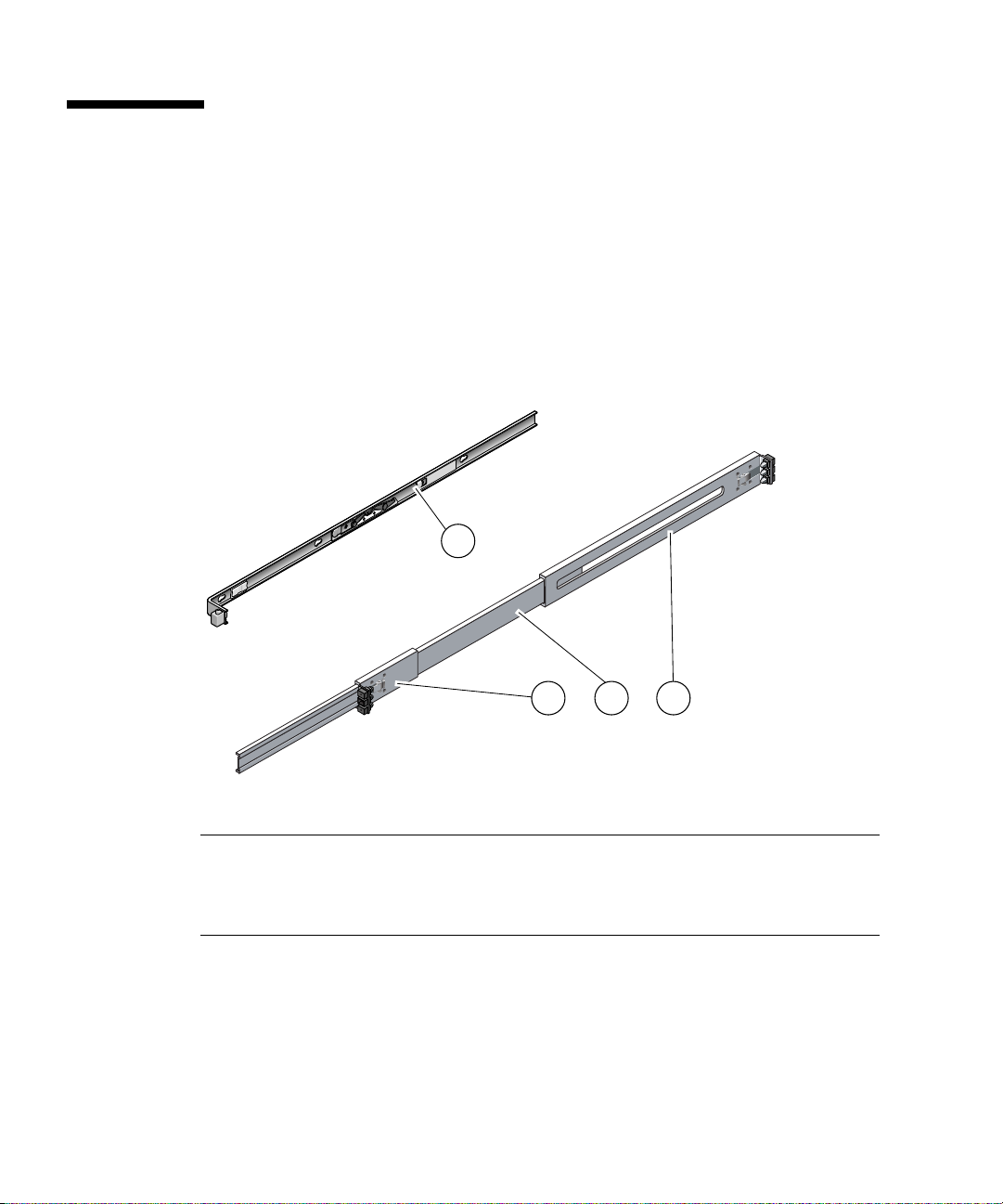
Slide Rail Assembly Notes for the Express Rail Rackmounting Kit
The express rail rackmount kit has two slide rail assemblies. A slide rail assembly
can be installed on either the right or left side of the rack.
Each slide rail assembly consists of a three-section slide rail and a removable
mounting bracket (
FIGURE C-1 Sections of the Express Rail Slide Rail Assembly
FIGURE C-1).
1
2
Figure Legend
1 Mounting bracket
2 Front section
3 Middle section
4 Rear section
■ The front, middle, and rear sections form the slide rail. The middle and rear sections
have holes for mounting and adjust to fit rack depths from 24 in. (61 cm) to
36.5 in. (93 cm). The front section can be extended to allow movement of the
server out of the rack.
68 SPARC Enterprise T5140 and T5240 Servers Installation Guide • February 2008
43
Page 95

■ The removable mounting bracket slides 14.5 in. (37 cm) out of the slide rail, then
locks in place. If you unlock the mounting bracket at this point, it slides an
additional 14.5 in. (37 cm) before separating from the slide rail. You can then
mount the mounting bracket to the right or left side of the server chassis.
■ Note that there are a total of six locks (FIGURE C-2) in a slide rail assembly. Four
are on the mounting bracket. Two locks are on the slide rail. The uses of these
locks are described in the following installation procedure.
Appendix C Installing the Servers With the Express Rail Rackmounting Kit 69
Page 96

FIGURE C-2 Locating the Locks on the Slide Rail Assembly for the SPARC Enterprise
T5240 Server
70 SPARC Enterprise T5140 and T5240 Servers Installation Guide • February 2008
Page 97

Installing the Servers in a Rack With Express Rails
Note – Ensure that you have all of the parts in the rackmount kit before you begin
the installation of the server.
The rackmount kit contains two slide rail assemblies, which can be installed on
either the right or left side of the rack.
A slide rail assembly consists of two parts, a slide rail and a removable mounting
bracket. The slide rail attaches to the rack posts. The mounting bracket attaches to
the server chassis.
▼ To Install the Slide Rail Assemblies
1. Pull both mounting brackets completely out of their respective slide rails.
a. Simultaneously press and hold the upper and lower lock buttons of the
slide rail lock (
FIGURE C-3).
Appendix C Installing the Servers With the Express Rail Rackmounting Kit 71
Page 98

FIGURE C-3 Unlocking the Express Rail Slide Rail Assembly
b. Pull the mounting bracket out until it stops.
72 SPARC Enterprise T5140 and T5240 Servers Installation Guide • February 2008
Page 99

c. Slide the mounting bracket release button to the left (FIGURE C-4), then slide
the mounting bracket completely out of the slide rail.
FIGURE C-4 Express Rail Mounting Bracket Release Button
Appendix C Installing the Servers With the Express Rail Rackmounting Kit 73
Page 100
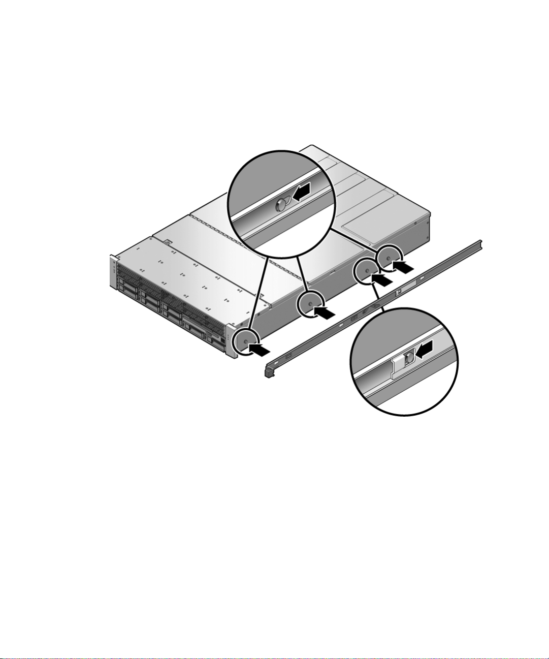
2. Attach a mounting bracket to the right side of the server chassis.
a. Position the mounting bracket against the chassis (
FIGURE C-5). Ensure that
the slide rail lock is at the front and the keyed openings on the mounting
bracket are aligned with the locating pins on the side of the chassis.
FIGURE C-5 Attaching an Express Rail Mounting Bracket to the Chassis
b. Ensure that the heads of the four locating pins protrude through the keyed
openings in the mounting bracket. Slide the mounting bracket toward the
front of the chassis until the bracket locks into place with an audible click.
c. Verify that all four locating pins are trapped in the keyed openings and that
the third from the front locating pin has engaged the mounting bracket lock
(
FIGURE C-5).
3. Attach the second mounting bracket to the left side of the server chassis.
4. Orient slide rails, ensuring that the ball bearing tracks (labeled FRONT) are
forward (
74 SPARC Enterprise T5140 and T5240 Servers Installation Guide • February 2008
FIGURE C-6).
 Loading...