

Page 1

Stylistic® ST5000 Series
Tablet PC
Technical
Reference
Guide
Page 2
Fujitsu Computer Systems Corporation has made every effort to
ensure the accuracy and completeness of this document. Because
ongoing development efforts are made to continually improve the
capabilities of our products, however, the data contained herein
represents Fujitsu design objectives and is provided for
comparative purposes; actual results may vary based on a variety
of factors. This product data does not constitute a warranty.
Specifications are subject to change without knowledge.
Fujitsu and the Fujitsu logo are registered trademarks of Fujitsu
Limited. Stylistic is a registered trademark of Fujitsu Computer
Systems Corporation.
IBM is a registered trademark of IBM Corporation.
PCMCIA and CardBus are registered trademarks of the Personal
Computer Memory Card International Association.
Intel and Pentium are registered trademarks of Intel Corporation.
Microsoft and Windows are registered trademarks of Microsoft
Corporation.
All other products are trademarks or registered trademarks of
their respective companies.
Warning
Handling the cord on this product will expose you to lead, a
chemical known to the State of California to cause birth
defects or other reproductive harm.
Wash hands after handling.
• Installing or removing a Memory Stick or SD
Card during your Tablet PC’s shutdown or
bootup process may damage the card and/or
your computer.
• Do not insert a card into a slot if there is water
or any other substance on the card as you may
permanently damage the card, your Tablet PC,
or both.
Copyright 2004 - Fujitsu Computer Systems Corporation. All
rights reserved. No part of this publication may be copied,
reproduced, or translated, without the prior written consent of
Fujitsu Computer Systems Corporation. No part of this
publication may be stored or transmitted in any electronic form
without the prior consent of Fujitsu Computer Systems
Corporation.
FPC58-1085-01
DECLARATION OF CONFORMITY
according to FCC Part 15
Responsible Party Name: Fujitsu Computer Systems Corporation
Address: 1250 E. Arques Avenue, Sunnyvale, CA 94085
Telephone: 408-746-6000
Declares that product: Model: Stylistic ST5000 Series Tablet PC
Complies with Part 15 of the FCC Rules
This device complies with Part 15 of the FCC rules. Operation is subject to the following two conditions:
(1) This device may not cause harmful interference, and, (2) This device must accept any interference
received, including interference that may cause undesired operation.
For more detailed information about the FCC rules and their applicability to the Stylistic ST5000 Series Tablet
PC, refer to “Agency Notices” on page 69 of this document.
Page 3

Table of Contents
About This Guide .............................................................................................................................. 1
Organization....................................................................................................................................................... 1
Related Documentation...................................................................................................................................... 2
Chapter 1
Stylistic ST5000 Tablet PC Features ............................................................................................... 3
Hardware Features ............................................................................................................................................. 3
PC Card Support .................................................................................................................................... 3
Internal Modem...................................................................................................................................... 3
Internal LAN.......................................................................................................................................... 3
ACPI Support......................................................................................................................................... 3
DMI Support .......................................................................................................................................... 3
USB Support.......................................................................................................................................... 4
Smart Card Support ............................................................................................................................... 4
SD Card/Memory Stick Support............................................................................................................ 4
IrDA Support ......................................................................................................................................... 4
IEEE 1394 Support ................................................................................................................................ 4
Software Features .............................................................................................................................................. 4
Supported Operating Systems................................................................................................................ 4
Pen Support............................................................................................................................................ 4
PC Card Support .................................................................................................................................... 5
Fujitsu Menu .......................................................................................................................................... 5
Chapter 2
Configuring the Stylistic ST5000 Tablet PC BIOS ........................................................................ 6
Permanent and Current BIOS Settings .............................................................................................................. 6
BIOS Setup Utility............................................................................................................................................. 6
Starting BIOS Setup............................................................................................................................... 6
Using BIOS Setup.................................................................................................................................. 7
Exiting BIOS Setup ............................................................................................................................... 8
BIOS Setup Main Menu Options........................................................................................................... 9
Primary Master Submenu Options......................................................................................................... 10
Advanced Menu Options ....................................................................................................................... 11
IrDA Port Configuration Submenu Options .......................................................................................... 12
Keyboard Features Submenu Options ................................................................................................... 13
Video Submenu Options ........................................................................................................................ 14
Internal Device Configurations Submenu.............................................................................................. 15
CPU Features Submenu ......................................................................................................................... 16
USB Features Submenu ......................................................................................................................... 17
Miscellaneous Configurations Submenu ............................................................................................... 18
Event Logging Submenu ....................................................................................................................... 19
Security Menu Options .......................................................................................................................... 20
Hard Disk Security Submenu ................................................................................................................ 22
Owner Information Submenu ................................................................................................................ 23
Boot Menu Options................................................................................................................................ 24
Boot Device Priority Submenu .............................................................................................................. 25
Info Menu .............................................................................................................................................. 26
Exit Menu Options................................................................................................................................. 27
Page 4

Chapter 3
Hardware Specifications .................................................................................................................. 28
General Specifications ....................................................................................................................................... 28
Digitizer Specifications...................................................................................................................................... 29
Display Specifications ....................................................................................................................................... 29
External Video Capabilities ............................................................................................................................... 30
Environmental Specifications ............................................................................................................................ 30
Peripheral Interface Specifications .................................................................................................................... 31
Physical Specifications ...................................................................................................................................... 32
Power System Specifications............................................................................................................................. 33
Internal Modem Specifications .......................................................................................................................... 34
Internal LAN Specifications .............................................................................................................................. 34
Agency Approval Specifications ....................................................................................................................... 35
Tablet Dock Specifications ................................................................................................................................ 35
Chapter 4
Peripheral Interfaces ........................................................................................................................ 36
DC Power Input ................................................................................................................................................ 36
Universal Serial Bus Port................................................................................................................................... 37
IrDA Port ........................................................................................................................................................... 37
Tablet Dock Interface Port................................................................................................................................. 38
Audio Jacks........................................................................................................................................................ 42
PC Card Port ...................................................................................................................................................... 43
Hard Drive Port.................................................................................................................................................. 45
RJ-45 LAN Port ................................................................................................................................................. 46
IEEE 1394 Port .................................................................................................................................................. 46
Chapter 5
System Power .................................................................................................................................... 48
System Power Hardware.................................................................................................................................... 48
Battery Pack........................................................................................................................................... 48
DC Power Inputs.................................................................................................................................... 49
Chapter 6
Installing Hardware Options ........................................................................................................... 50
Installing/Removing a DIMM Module .............................................................................................................. 50
Installing a Memory Module ................................................................................................................. 50
Removing a Memory Module................................................................................................................ 51
Replacing/Installing a Wireless LAN Module.................................................................................................. 52
Removing a Wireless LAN Module ...................................................................................................... 52
Installing a Wireless LAN Module........................................................................................................ 52
Replacing the IDE Hard Drive........................................................................................................................... 54
Removing the Hard Drive...................................................................................................................... 54
Installing the Hard Drive ....................................................................................................................... 55
AT Command Set ............................................................................................................................. 56
AT Commands Table......................................................................................................................................... 57
AT Data Commands .............................................................................................................................. 57
AT Fax (Class1) Commands.................................................................................................................. 62
V.25ter AT Commands.......................................................................................................................... 63
S Register Table................................................................................................................................................. 64
Result Codes Summary...................................................................................................................................... 67
Agency Notices .................................................................................................................................. 69
Page 5

About This Guide
This guide provides technical information on the Fujitsu Stylistic ST5000 Tablet PC for technicians, hardware
developers, and software developers.
Organization 0
This guide is organized as follows:
• Chapter 1: Tablet PC Features
This chapter discusses some of the system’s main features and technology.
• Chapter 2: Configuring the Stylistic ST5000 Tablet PC BIOS
This chapter provides details on using BIOS Setup Utility for the Stylistic ST5000 Tablet PC. BIOS configuration
options are explained in detail.
• Chapter 3: Hardware Specifications
This chapter gives hardware specifications on the Tablet PC system. Industry standards supported by the Stylistic
ST5000 Tablet PC are listed.
• Chapter 4: Peripheral Interfaces
This chapter provides details on peripheral interfaces provided by the Stylistic ST5000 Tablet PC and the Stylistic
ST5000 Tablet Dock.
• Chapter 5: System Power
This chapter provides information on the Tablet PC’s system power hardware.
• Chapter 6: Installing Hardware Options
This chapter gives detailed instructions on installing hardware options such as PCMCIA, DIMM, and WLAN
cards, as well as the IDE Hard Drive.
• Appendix A: AT Command Set
This appendix provides a detailed list of AT commands used by the Tablet PC’s modem, including AT
Commands, S Register Table, and Result Codes Summary information.
• Appendix B: Agency Notices
This appendix states notices required by regulatory agencies in the United States and Canada that apply to the
Stylistic ST5000.
1
Page 6

Related Documentation 0
Documentation relating to the Stylistic ST5000 Tablet PC is listed below. Refer to these documents for details on
topics not covered in this guide.
Stylistic ST5000 User’s Guide
This guide provides an introduction to the Stylistic ST5000 Tablet PC’s basic functions for the end user.
Stylistic ST5000 Tablet Dock User’s Guide
This guide gives instructions on using the Stylistic ST5000 Tablet Dock.
The following documents, available from retail booksellers, contain additional information about software
preinstalled on the Stylistic ST5000 Tablet PC.
Microsoft Windows XP Professional Resource Kit (ISBN: 0-7356-1974-3)
This manual is a technical guide for installing, configuring, and supporting Windows XP and is published by
Microsoft Press, 1-800-MSPRESS in the U.S. as well as from retail book sellers.
The following resources contain information on software development tools for Windows:
Microsoft Developer’s Network
The Microsoft Developer’s Network web site provides links to information on application programming
interfaces (APIs) used with Microsoft Windows. The site address is <MSDN.Microsoft.com>.
The following documents provide information on industry standards supported by the Stylistic ST5000 Tablet PC.
Advanced Configuration and Power Interface (ACPI) Specification, Revision 1.0
The ACPI specification was developed by Microsoft, Intel, and Toshiba to manage device control in order to
conserve power. The specification and additional detailed information is available at the ACPI web site,
<http://www.acpi.info/index.html>.
PC Card Standards
The Stylistic ST5000 Tablet PC and supporting system software comply with PCMCIA and PC Card standards
specifications up to and including the PC Card Standard February 1995 (also referred to as PC Card Standard
Release 3.0 in this document and other related documentation). PC Card standards are published by: Personal
Computer Memory Card International Association, 2635 North First Street, Suite 209, San Jose, CA 95134,
<http://www.pcmcia.org/>, (408) 433-CARD (2273).
IrDA Standards
The IrDA port on the Stylistic ST5000 Tablet PC is compliant with IrDA (Infrared Data Association) Standard
Version 1.1 published by: Infrared Data Association, <http://www.irda.org>.
Universal Serial Bus Specification
The Universal Serial Bus (USB) ports on the Stylistic ST5000 Tablet PC and docking peripherals are compliant
with the Universal Serial Bus Specification Version 2.0. Refer to this specification for USB details including: cable
requirements, topology, and USB power distribution. This specification and other technical documents regarding
USB are available on the Universal Serial Bus Implementer’s Forum home page at <http://www.usb.org/>.
Related Documentation 2
Page 7

Chapter 1
Stylistic ST5000 Tablet PC Features
This chapter provides an introduction to the Stylistic ST5000 Tablet PC system hardware and software and gives an
overview of some of the Tablet PC’s features. Detailed specifications on the features discussed in this chapter are
given in other chapters of this guide.
The Stylistic ST5000 computer series is designed for the Microsoft Windows XP Tablet PC Edition. The system uses
an active digitizer and conforms to the Windows Tablet PC standards.
The Stylistic ST5000 Tablet PC system has been tested by Windows Hardware Quality Labs (WHQL) at Microsoft
Corporation and is compliant with PC2001 system design guidelines.
Hardware Features 1
PC Card Support 1
The Stylistic ST5000 Tablet PC is equipped with a PC Card slot that allows you to install a Type I or II PC Card. The
PC Card slot is compliant with PC CardBus Standard Release 3.0 and provides support for the following PC Card
features:
• Multivoltage 3.3/5 V PC Cards (detected automatically)
• CardBus (PCI bridge) type PC Cards
• Supports PCIC (PC Card I/O Card) protocol
• Backward compatibility with previous PC Card Standard Release level PC Cards
Internal Modem 1
The Stylistic ST5000 Tablet PCs are equipped with an internal 56 Kbps* modem. (Note: The 56 Kbps rate is nominal;
due to FCC restrictions, actual rates are limited to 53 Kbps.)
For details on the built-in modem, see “Internal Modem Specifications” on page 34.
Internal LAN 1
The Stylistic ST5000 Tablet PCs are equipped with an internal wired 10/100/1000* Base-T/Tx Ethernet LAN.
*1000 Mbps, commonly referred to as Gigabit Ethernet.
ACPI Support 1
The Stylistic ST5000 Tablet PC supports the Advanced Configuration and Power Interface (ACPI) Specification,
revision 1.0, in all system configurations. With ACPI, power management features are controlled and configured
primarily by the BIOS and BIOS settings. The ACPI specifications allow for additional control over power
management features such as state transitions and device timeouts. Refer to the ACPI specifications and the
documentation for your operating system regarding power management with ACPI.
DMI Support 1
The Stylistic ST5000 supports the Distributed Management Interface (DMI). DMI provides a framework for managing
the variety of components within the tablet PC. The Event Logging menu in the BIOS allows you to configure the
DMI event logging options (see “Event Logging Submenu” on page 19).
3
Page 8

USB Support 1
The Universal Serial Bus (USB) design is the primary interface for your tablet PC. The Stylistic ST5000 USB ports are
compliant with Universal Serial Bus Specification 2.0. For more information on the USB interface, refer to “Universal
Serial Bus Port” on page 37.
Smart Card Support 1
The dedicated Smart Card slot allows you to install a Smart Card, on which you can store information such as
medical information or electronic “cash”.
SD Card/Memory Stick Support 1
The Secure Digital (SD)/Memory Stick card slot allows you to install a flash memory card for data storage.
IrDA Support 1
There are three infrared ports on your Stylistic ST5000 Tablet PC, two infrared keyboard/mouse ports and an IrDA/
FIR port. The keyboard/mouse ports are used for receiving communications from an infrared keyboard or mouse.
(Note that the infrared keyboard/mouse ports are receive-only, one-direction serial ports.) The IrDA/FIR port is
used for communications compliant with IrDA Standard Revision 1.1.
IEEE 1394 Support 1
The Institute of Electrical and Electronics Engineers, Inc. (IEEE) standard 1394 architecture supports a fast external
bus that allows transfer rates of up to 400 Mbps. IEEE 1394 (also known as “Firewire” or “iLink” by other vendors)
allows connection of the tablet PC with peripherals such as digital video cameras, providing for fast transfer of the
large files. For more information on the IEEE 1394 port, refer to “IEEE 1394 Port” on page 46.
Software Features 1
Supported Operating Systems 1
The Stylistic ST5000 Tablet PC is distributed with Microsoft Windows XP Tablet PC Edition pre-installed.
Licensing and user documentation for the operating system installed on your system is also included with the Tablet
PC. For details on the operating system, refer to the documentation provided, or refer to the documents listed in
“Related Documentation” in the About This Manual section of this guide.
Note: MS-DOS is not supported as an end-user operating environment. Support for MS-DOS is limited to the use of
configuration and other support utilities designed for the Stylistic ST5000 system.
Pen Support 1
The Stylistic ST5000 Tablet PC has an active digitizer and employs the Microsoft Windows XP for Tablet PC as its
operating system. As such, the pen, on-screen keyboard, and handwriting recognition utilities are part of the tablet
PC operating system.
There are three ways to access the pen utilities:
• Double-click on the “Change tablet and pen settings” icon in the system tray in the lower right of the screen,
• Select Start -> Control Panel -> Tablet and Pen Settings, or,
• Click on the Fujitsu Menu icon in the system tray (or press the [Fn] button twice in quick succession), and select
Tablet and Pen Settings from the menu.
Software Features 4
Page 9

To open the on-screen keyboard:
• Click the Tablet PC Input Panel icon adjacent to the Start button, or,
• Click on the Fujitsu Menu icon in the system tray (or press the [Fn] button twice in quick succession), and select
Tablet PC Keyboard from the menu.
To access the Pen Configuration applet (developed by Fujitsu), click Start -> Control Panel -> Fujitsu Pen Settings.
PC Card Support 1
The Stylistic ST5000 Tablet PC fully supports the PC Card standard release 3.0. System resources for PC Cards are
configured automatically by Windows XP.
Fujitsu Menu 1
The Fujitsu Menu provides a handy list of shortcuts to commonly-used utilities. To open the Fujitsu Menu, click on
the Fujitsu Menu icon in the system tray at the bottom right of the screen or press the [Fn] button twice in quick
succession.
The following utilities can be accessed directly from the Fujitsu Menu:
• Control Panel
•Tablet PC Keyboard
• Tablet and Pen Settings
• Fujitsu Display Controls
• Brightness Control
• Sounds and Audio Devices
• Capture Screen
•Capture Window
•Organize Favorites
•Power Options
•Printers and Faxes
• LCD Brightness Min.
• LCD Brightness Max.
• Enable/Disable Button Panel
• Fujitsu Menu Settings
Any of these utilities can be added or deleted from the Fujitsu Menu by clicking on the Fujitsu Menu Settings button
and checking or unchecking the utility then applying your changes. Additionally, any new applications can be added
to the menu by clicking Fujitsu Menu Settings ->, then browsing to the application you want to add.
Software Features 5
Page 10

Chapter 2
Configuring the Stylistic ST5000 Tablet PC BIOS
This chapter provides instructions on how to use the Setup Utility to configure the Stylistic ST5000 Tablet PC BIOS.
Permanent and Current BIOS Settings 2
Some BIOS configuration utilities allow you to select permanent and/or current settings when configuring BIOS
options. When you change a permanent setting, BIOS parameters stored in CMOS memory are changed and the new
setting is applied after the system is restarted. When you change a current setting, BIOS parameters stored in
dynamic memory are changed and the new setting is applied for the current session. Also, note that a change to the
current setting only remains in effect until the system is restarted or shut down.
BIOS data resides in the system’s CMOS memory. When the system is powered on, BIOS data is copied or
“shadowed” into the system’s dynamic memory and the system runs using BIOS parameters stored in dynamic
memory.
BIOS Setup Utility 2
The BIOS Setup Utility is a configuration utility that you can use to change your system’s permanent BIOS settings.
The BIOS Setup Utility application is stored in the BIOS flash ROM. (BIOS Setup values or settings are stored in
CMOS memory.) Instructions for starting and running BIOS Setup are given in the following discussions.
Starting BIOS Setup 2
To start BIOS Setup, restart your system and when the message “Tap, Click, or Enter for System Utilities” is
displayed in the status bar at the bottom of the screen, tap anywhere on the screen with your tablet pen. Select
“Launch System Setup” from the pop-up menu that appears. You can also press the [Alt] button (the button closest
to the corner of the display), or press [F2] on an external keyboard to launch BIOS Setup.
The system starts the BIOS Setup Utility and the BIOS Setup Main menu is displayed.
Options and settings for menus in BIOS Setup are described in tables appearing later in this chapter.
Permanent and Current BIOS Settings 6
Page 11
Using BIOS Setup 2
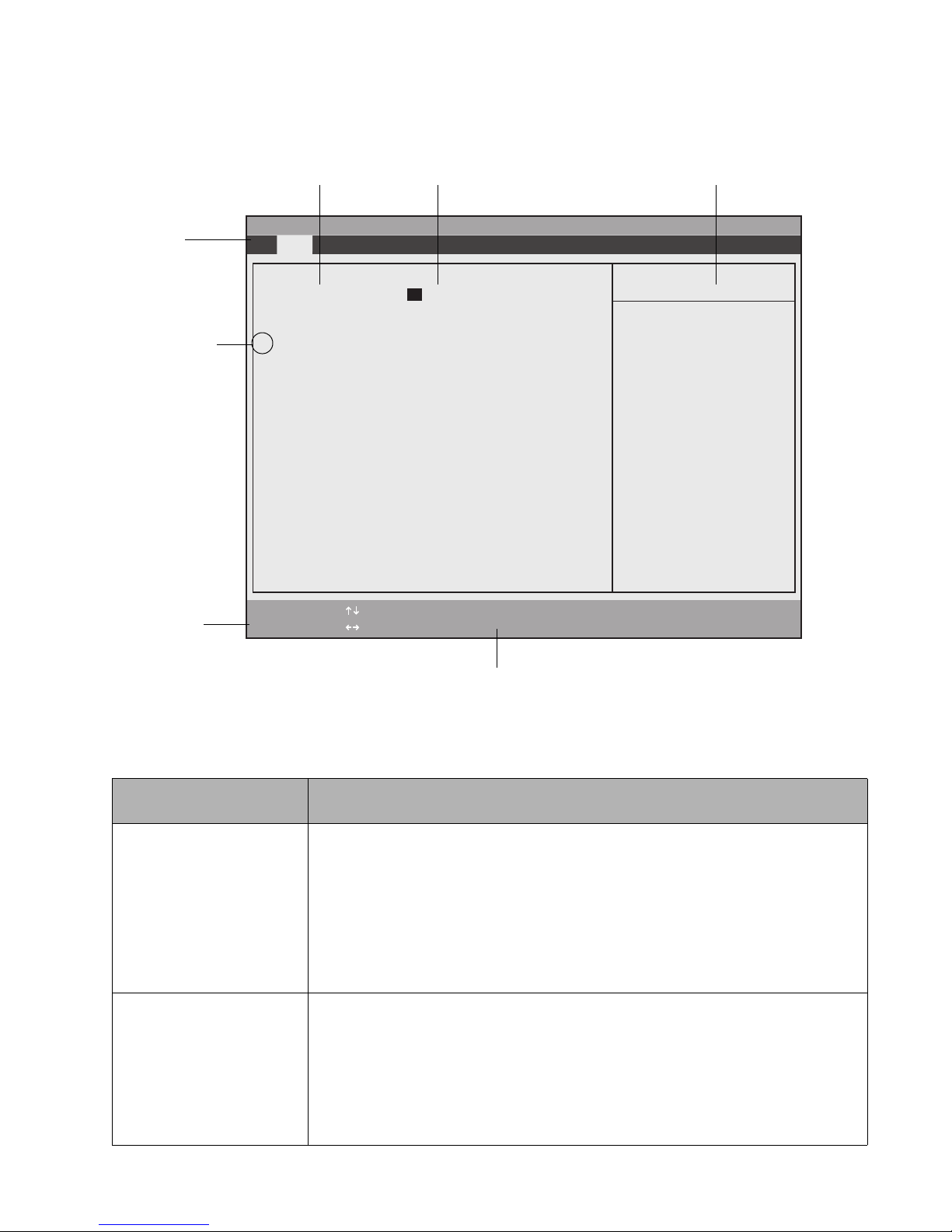
Once the BIOS Setup Utility is started, you can use BIOS Setup to change your system BIOS settings. The BIOS Setup
screen consists of a menu bar, menu items, a command bar, and a window for item-specific help as shown below.
BIOS Configuration Options BIOS Configuration Settings Item-Specific Help Window
Menu Bar
(Triangle symbol
indicates that a
submenu is
available)
Command Bar
PhoenixBIOS Setup Utility
Main Advanced Security Boot Info Exit
System Time: [02:34:56]
System Date: [01/16/2004]
▲
Primary Master [FUJITSU MHT2060AT -(PM)]
Language: [English (US)]
F1 Help
ESC Exit
Select Item
Select Menu
- Change Values Space
Enter Select Sub-Menu
Highlighted text indicates equivalent keyboard command
▲
Item Specific Help
Adjust calendar clock.
<Tab>, <Shift-Tab>, or
<Enter> selects field.
F9 Setup Defaults
F10 Save and Exit
Figure 2-1 BIOS Setup Screen
Instructions for selecting and changing BIOS options and navigating BIOS Setup menus:
If you want to... Do one of these...
Select a BIOS Setup menu
from the menu bar
Select a BIOS option To highlight an option in the list of items for a given menu, do one of the following:
To move left and right to highlight the menu and display a list of menu options, do
one of the following:
• Press either side of the lower navigation button (the one that is farthest from the
application buttons)
• Tap on the menu name in the menu bar
• Tap on the right or left side of the Select Menu field in the command bar
• Use the right or left arrow keys on an external keyboard
• Press either side of the upper navigation button (the one that is closest to the
application buttons)
• Tap on the setting field for the option
• Tap on the right or left side of the Select Item field in the Command Bar
• Use the up and down arrow keys on an external keyboard
BIOS Setup Utility 7
Page 12

If you want to... Do one of these...
Change the setting of a
selected BIOS option
Access a pop-up menu
with a list all possible
settings for a given BIOS
option
Select and enter a submenu To select and enter a submenu, do one of the following:
View Item-Specific Help for
a BIOS option
View General Help for
BIOS Setup
To cycle through the list of possible settings, do one of the following:
• Tap directly on the setting field
• Tap on the highlighted commands to the right or left of Change Values in the
command bar
• Use the -, +, and space keys on an external keyboard
• Press the Display Orientation button (third button from the right)
Tap on the [option], then press the [Ent] application button. Tap on the setting of
your choice to select it. You can also hold the pen barrel button while tapping to bring
up the pop-up menu.
• Tap on the submenu name, then tap again to activate it.
• Select the submenu using the up and down arrow keys on an external keyboard
and press Enter, or press the [Ent] application button.
Select the option. Item-specific help is displayed in the Item Specific Help panel on the
right-hand side of the screen.
Tap on Help in the command bar or press F1 on your external keyboard. The BIOS Setup
help screen is displayed giving general instructions for using BIOS Setup
Exit BIOS Setup To exit the BIOS Setup Utility, do one of the following:
• Choose the appropriate option from the Exit menu
• Tap Save and Exit in the command bar
• Press F10 on an external keyboard.
Load factory default
settings for all BIOS options
To load the factory BIOS default settings, do one of the following:
• Press F9 on an external keyboard
• Select Setup Defaults from the command bar
• Select Load Setup Defaults from the Exit menu
Exiting BIOS Setup 2
Once you have finished making changes in BIOS Setup, you must exit BIOS Setup and allow the system to boot to
apply your configuration changes. You can exit BIOS Setup by selecting options in the Exit menu. The Exit menu
includes options that allow you to load default BIOS settings, load previous settings, discard your changes, save your
changes, and exit BIOS Setup. For details on Exit menu options, see “Exit Menu Options” on page 27.
BIOS Setup Utility 8
Page 13
BIOS Setup Main Menu Options 2
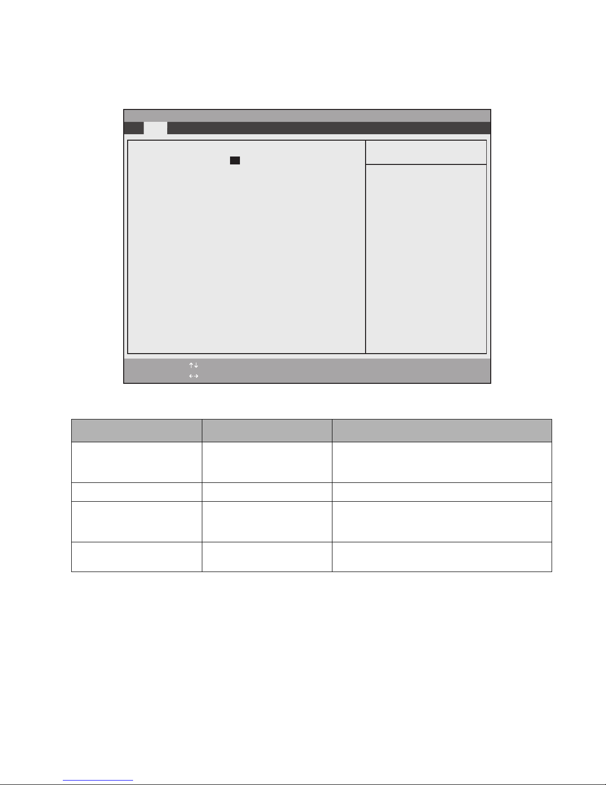
BIOS Setup Main menu options are given in Table 2-1. (Options and settings for other BIOS Setup menus are
described in the tables that follow.) The default setting for each option is listed in bold type when applicable.
PhoenixBIOS Setup Utility
Main Advanced Security Boot Info Exit
System Time: [02:34:56]
Item Specific Help
System Date: [01/16/2004]
▲
Primary Master [FUJITSU MHT2060AT -(PM)]
Language: [English (US)]
F1 Help
ESC Exit
Select Item
Select Menu
- Change Values Space
Enter Select Sub-Menu
▲
Adjust calendar clock.
<Tab>, <Shift-Tab>, or
<Enter> selects field.
F9 Setup Defaults
F10 Save and Exit
Table 2-1. BIOS Setup Main Menu Options
Option Settings Description
System Time 00:00:00 to 23:59:59 Real Time Clock (RTC) setting in hours, minutes, and
seconds. Note that the system time option uses a 24
hour format.
System Date 01/01/1980 to 12/31/2099 RTC calendar setting in month/day/year format.
Primary Master Submenu ___ Select this field to access the primary disk drive
submenu. (See “Primary Master Options” later in this
section.)
Language English
Japanese
Select the display language for the BIOS.
BIOS Setup Utility 9
Page 14
Primary Master Submenu Options 2
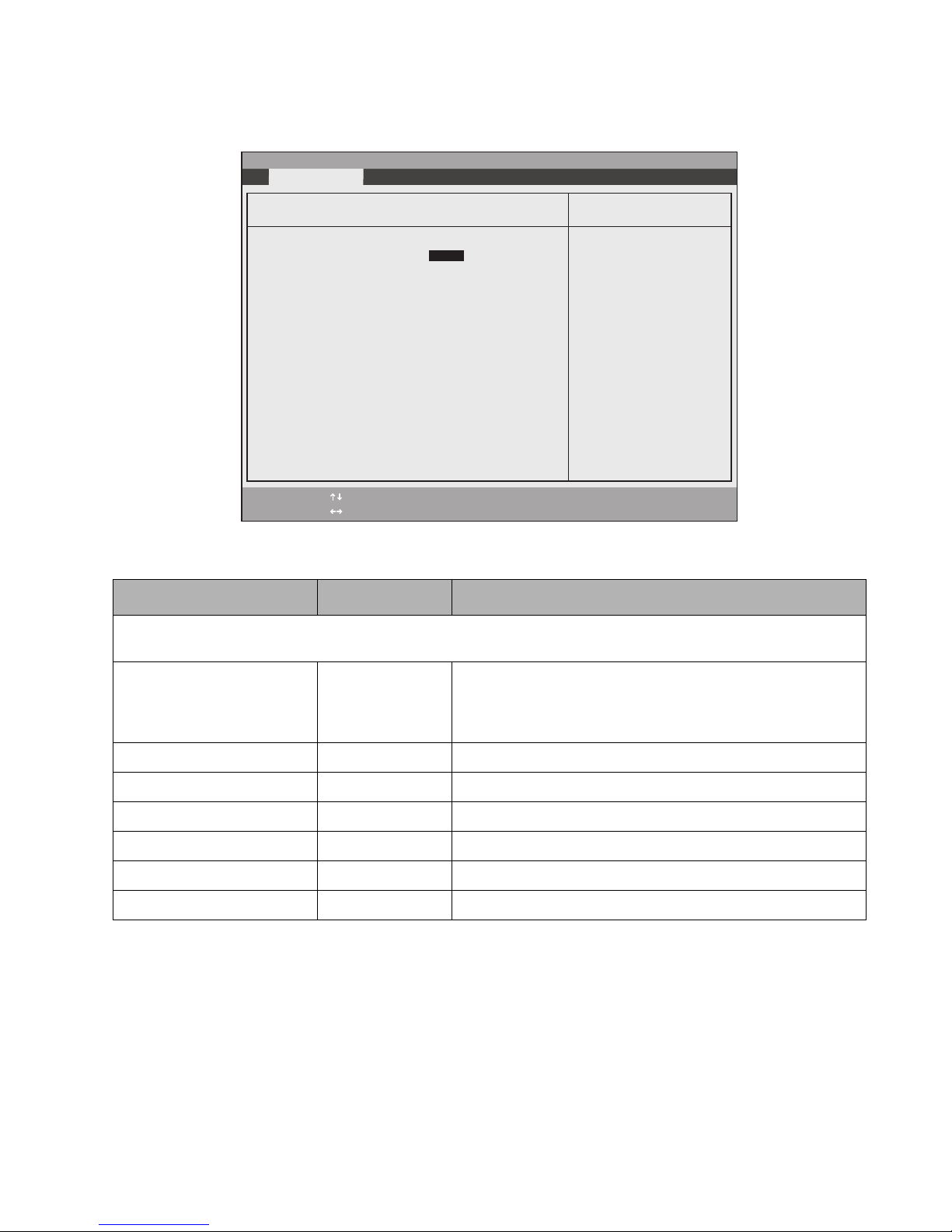
Options and settings for the Primary Master Submenu are given in Table 2-2.
PhoenixBIOS Setup Utility
Exit Submenu
Primary Master [FUJITSU MHT2060AT-(PM)]
Type: [Auto]
LBA Format
Total Sectors: 117210240
Maximum Capacity: 60012MB
Multi-Sector Transfers: [16 Sectors]
LBA Mode Control: [Enabled]
Transfer Mode: [Multiword DMA 2]
Ultra DMA Mode: [Mode 5]
F1 Help
ESC Exit
Select Item
Select Menu
- Change Values Space
Enter Select Sub-Menu
▲
Item Specific Help
Select ATA/ATAPI drive
installed here.
[Auto]
The BIOS auto-types the
drive on boot time.
Except [Auto]
You enter parameters of
the drive.
[None]
The drive is disabled.
F9 Setup Defaults
F10 Save and Exit
Table 2-2. BIOS Setup Primary Master Configuration Options
Option Settings Description
Note: the following settings reflect the fields when Auto is selected as the type. If Hard Disk or CD-ROM are selected,
additional objects are displayed, such as Cylinders and Heads.
Type : Auto
None
CD-ROM
Hard Disk
Select [Auto] to load configuration parameters from the hard drive
automatically. Selecting CD-ROM or Hard Disk allows you to
change the parameters of the selected drive. Selecting [None]
disables the hard drive.
Total Sectors: ___ Display only.
Maximum Capacity: xxxxMB Display only.
Multi-Sector Transfers: 16 Sectors Display only.
LBA Mode Control: Enabled Display only.
Transfer Mode: Multiword DMA 2 Display only.
Ultra DMA Mode: Disabled Display only.
BIOS Setup Utility 10
Page 15
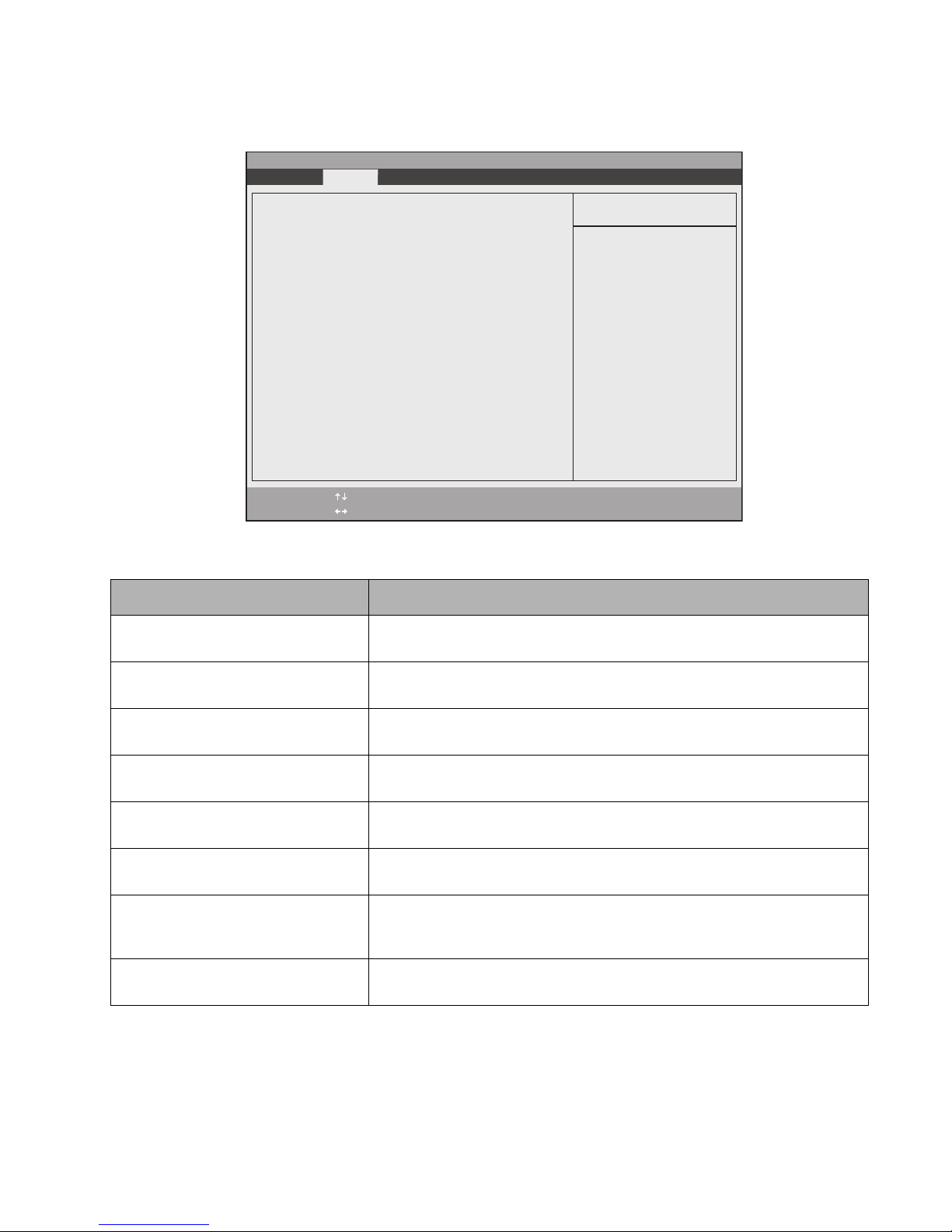
Advanced Menu Options 2
Options in the Advanced menu are described in Table 2-3.
PhoenixBIOS Setup Utility
Main Advanced Security Boot Info Exit
▲ ▲ ▲ ▲ ▲ ▲ ▲ ▲
IrDA Port Configurations
Keyboard Features
Video Features
Internal Device Configurations
CPU Features
USB Features
Miscellaneous Configurations
Event Logging
F1 Help
ESC Exit
Select Item
Select Menu
- Change Values Space
Enter Select Sub-Menu
▲
Item Specific Help
Configures IrDA ports.
F9 Setup Defaults
F10 Save and Exit
Table 2-3. BIOS Setup Advanced Menu Options
Option Description
IrDA Port Configurations Submenu Enter this submenu to configure the infrared port features. (See “IrDA Port
Configurations Submenu Options” on page 12 for details.)
Keyboard Features Submenu Enter this submenu to configure the system keyboard. (See “Keyboard Features
Submenu Options” on page 13 for details).
Video Features Submenu Enter this submenu to select system resources for the video controller. (See
“Video Features Submenu Options” on page 14 for details.)
Internal Device
Configurations Submenu
Enter this menu to configure additional device controllers. (See “Internal Device
Configurations Submenu Options” on page 15 for details.)
CPU Features Submenu Enter this submenu to change CPU features. (See “CPU Features Submenu
Options” on page 16 for details).
USB Features Submenu Enter this submenu to change USB features. (See “USB Features Submenu
Options” on page 17 for details).
Miscellaneous Configurations Submenu Enter this submenu to change several miscellaneous features, such as Wake Up
On LAN. (See “Miscellaneous Configurations Submenu Options” on page 18 for
details).
Event Logging Submenu Enter this submenu to view the Event Log features. (See “Event Logging
Submenu Options” on page 19 for details).
BIOS Setup Utility 11
Page 16
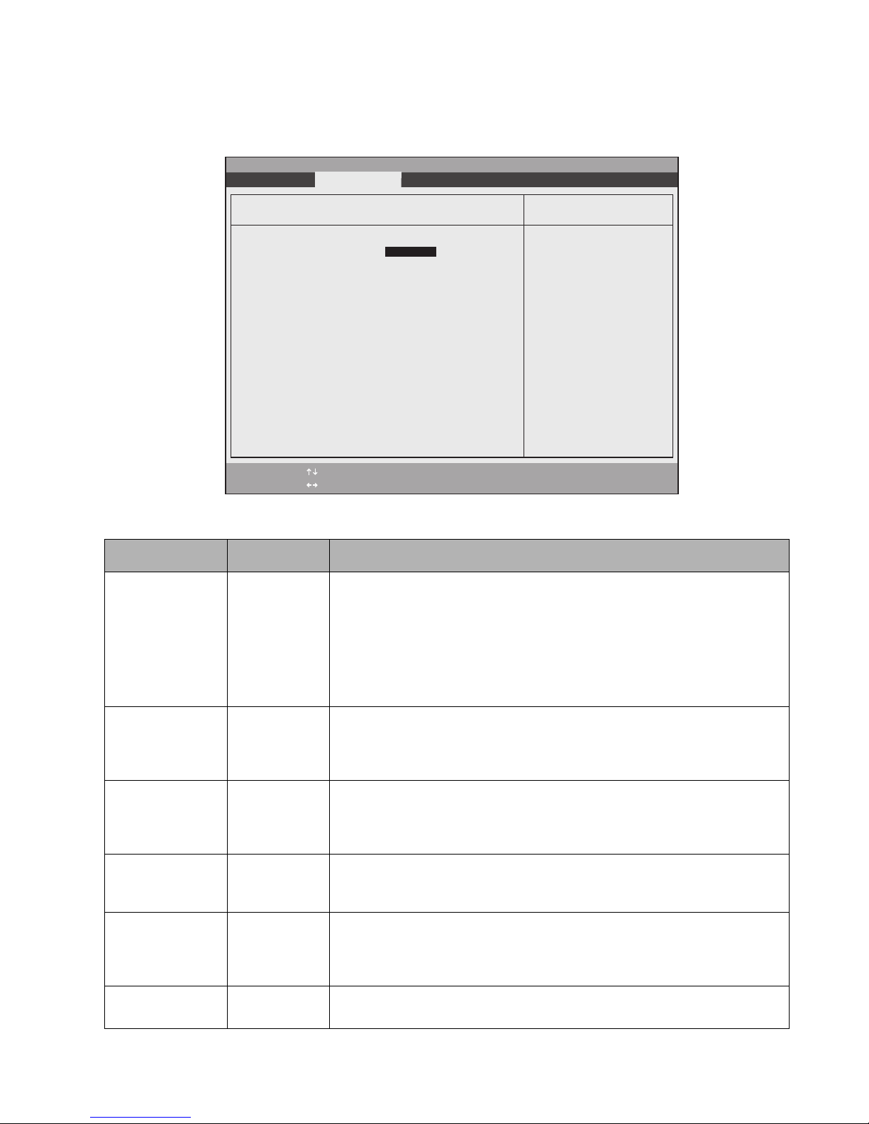
IrDA Port Configuration Submenu Options 2
Configuration options for the IrDA Port Configuration submenu are given in Table 2-4. Note that some peripheral
interfaces are only available when using a device attached to the Tablet Dock.
PhoenixBIOS Setup Utility
Exit Submenu
IrDA Port Configurations
Infrared Port: [Enabled]
Mode: [FIR]
I/O Address: [2E8-2EF]
Interrupt: [IRQ 3]
I/O Address: [400-43F]
DMA Channel: [DMA 3]
F1 Help
ESC Exit
Select Item
Select Menu
- Change Values Space
Enter Select Sub-Menu
▲
Table 2-4. IrDA Port Configurations Submenu Options
Option Settings Description
Infrared Port: Enabled
Auto
Disabled
Determines whether the infrared port is active and the method used to configure
the infrared port.
• Select [Auto] to allow the BIOS or operating system to configure the port
automatically.
• Select [Enabled] to configure the I/O Address and Interrupt options manually
in BIOS setup.
• Select [Disabled] to turn off the infrared port.
Item Specific Help
[Disabled]
The port is disabled.
[Enabled]
The port is enabled
with user configuration.
[Auto]
Plug & Play OS
configure the port.
F9 Setup Defaults
F10 Save and Exit
Mode: IrDA
FIR
I/O Address 3F8 - 3FF
2F8 - 2FF
3E8 - 3EF
2E8 - 2EF
Interrupt: IRQ 3
IRQ 10
IRQ 11
I/O Address: 400 - 43F
480 - 4BF
500 - 53F
580 - 5BF
DMA Channel DMA 1
DMA 3
Determines which physical interface the infrared port is assigned to. Select IrDA
to use the IrDA port in Standard IR (SIR) mode (115 Kbps). Select FIR to use the
IrDA port in Fast IR mode (4 Mbps). Note: The Infrared port option must be
Enabled before this setting can be changed.
Determines the base I/O address and interrupt request level used for the infrared
port. The Infrared Port option must be set to [Enabled] before this setting can be
changed.
Determines the interrupt number for the infrared port. Note: The Infrared port
option must be Enabled before this setting can be changed.
Determines the base I/O address and interrupt request level used for the Fast
Infrared port. FIR Mode must be set before this setting can be changed.
Determines the DMA channel assigned to the infrared port when using Fast IR
mode. This option is only selectable when the Infrared Port Mode setting is FIR.
BIOS Setup Utility 12
Page 17
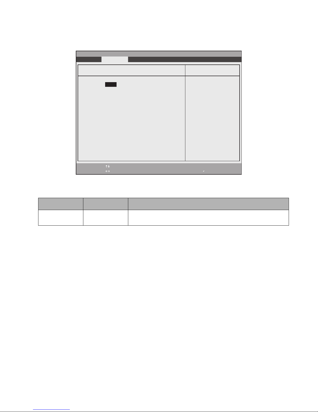
Keyboard Features Submenu Options 2
Configuration options for the Keyboard Features submenu are given in Table 2-5.
PhoenixBIOS Setup Utility
Exit Submenu
Keyboard Features
Numlock:
F1 Help
ESC Exit
[Off]
Select Item
Select Menu
-/Space
Enter
Select power-on state
for Numlock.
Change Values
▲
Select Sub-Menu
Table 2-5. Keyboard Features Submenu Options
Option Settings Description
Numlock On
Off
This option determines the state of the NumLock key when the system is
powered on.
Item Specific Help
F9 Setup Defaults
F10 Save and Exit
BIOS Setup Utility 13
Page 18
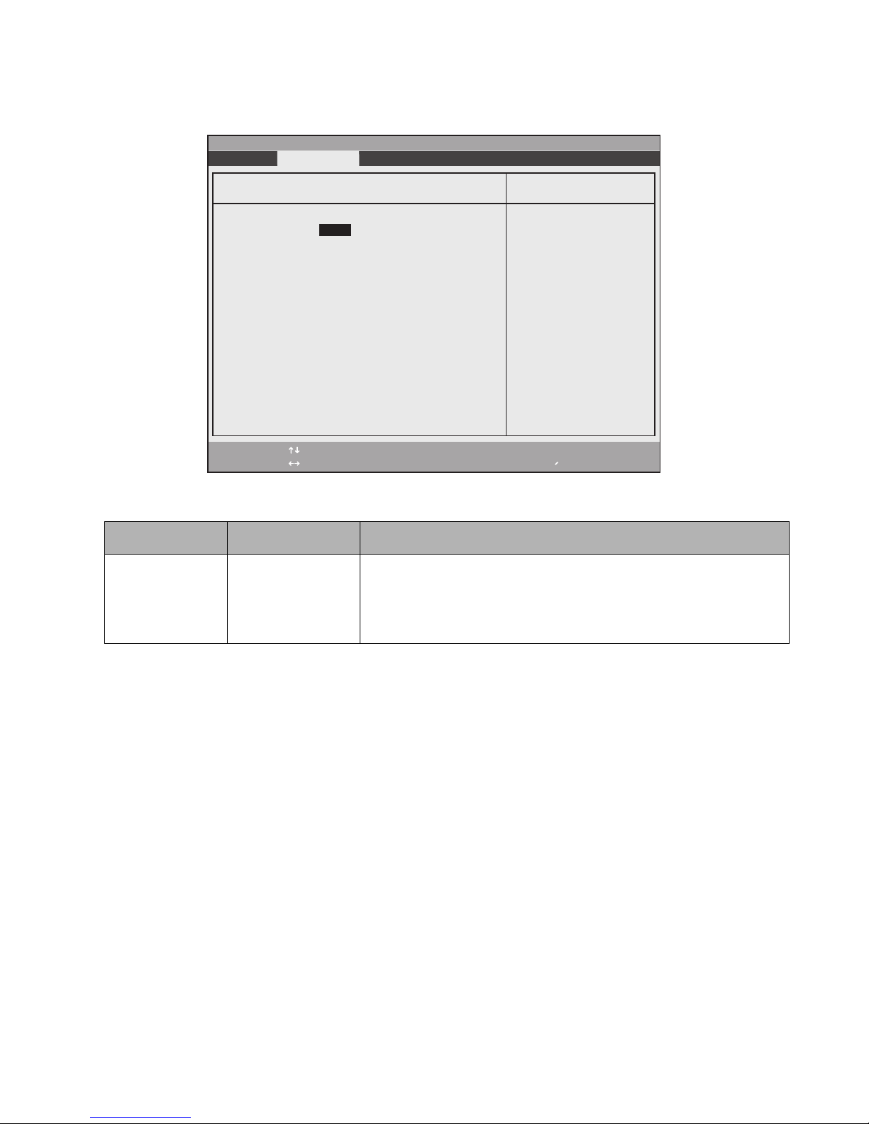
Video Submenu Options 2
Options for the Video Features submenu are given in Table 2-6.
PhoenixBIOS Setup Utility
Exit Submenu
Video Features
Display: [Auto]]
F1 Help
ESC Exit
Select Item
Select Menu
-/Space
Enter
Change Values
▲
Select Sub-Menu
Select display terminal.
Table 2-6. Video Features Submenu Options
Option Settings Description
Display Internal Flat Panel
External
Auto
Determines the default display device.
Select the appropriate option to choose the LCD (internal flat panel) or an
external video monitor as the default display device. Or select Auto to allow
the system to select the display automatically.
Item Specific Help
F9 Setup Defaults
F10 Save and Exit
BIOS Setup Utility 14
Page 19

Internal Device Configurations Submenu 2
Options for the Internal Device Configurations submenu are given in Table 2-7.
PhoenixBIOS Setup Utility
Exit Submenu
Internal Device Configurations
IDE Controller: [Enabled]
Modem Controller: [Enabled]
LAN Controller: [Enabled]
F1 Help
ESC Exit
Select Item
Select Menu
-/Space
Enter
Change Values
▲
Select Sub-Menu
[Disabled]
IDE port is disabled.
[Enabled]
IDE port is enabled.
Table 2-7. Internal Device Configurations Submenu Options
Option Settings Description
IDE Controller: Disabled
Enabled
When [Enabled] is selected, the IDE port is enabled.
When [Disabled] is selected, the IDE port is disabled.
Item Specific Help
F9 Setup Defaults
F10 Save and Exit
Modem Controller: Disabled
Enabled
LAN Controller: Disabled
Enabled
When [Enabled] is selected, the modem device is enabled.
When [Disabled] is selected, the modem device is disabled.
When [Enabled] is selected, the LAN is enabled.
When [Disabled] is selected, the LAN is disabled.
BIOS Setup Utility 15
Page 20
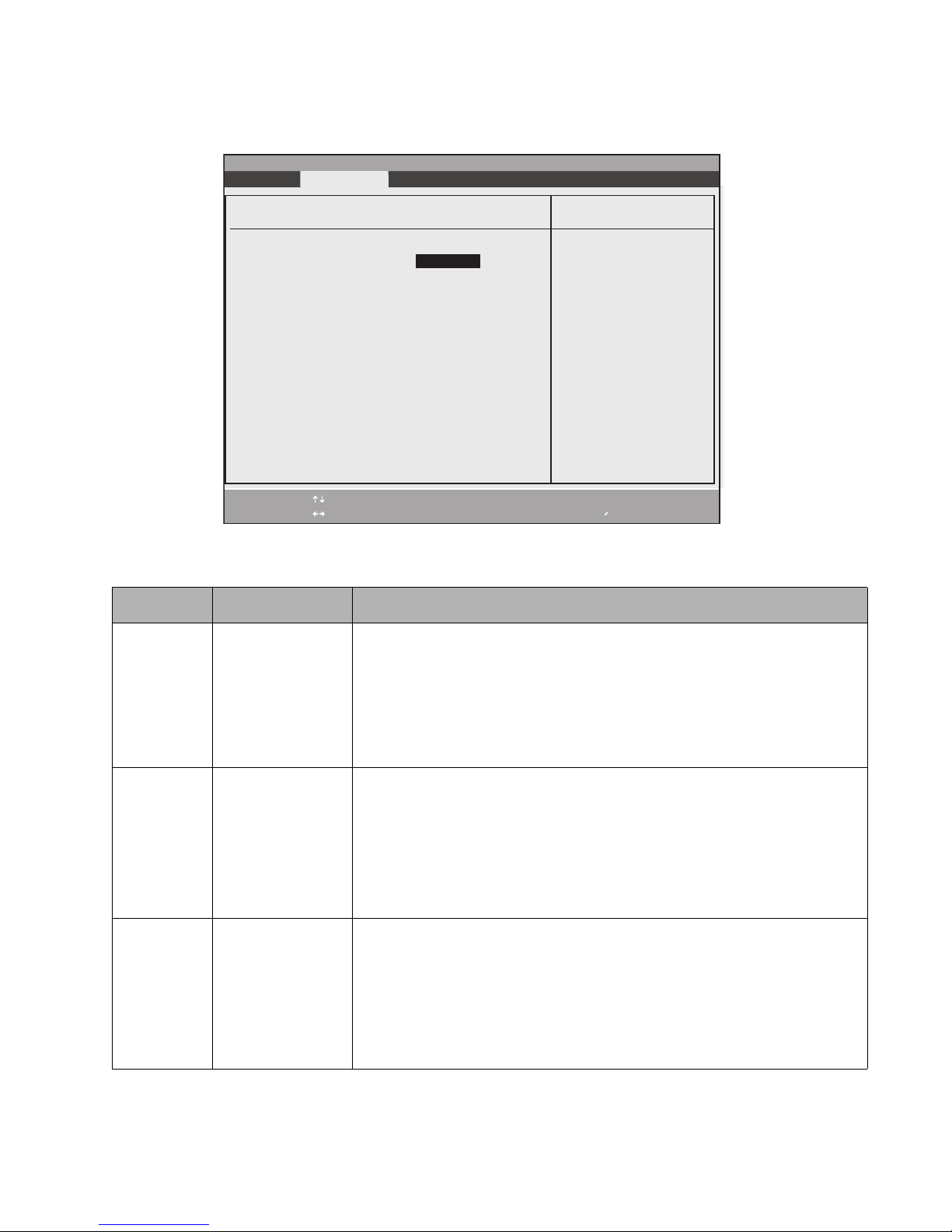
CPU Features Submenu 2
Options for the CPU Features submenu are given in Table 2-8.
PhoenixBIOS Setup Utility
Exit Submenu
CPU Features
SpeedStep(TM) Technology: [Enabled]
On Battery: [Battery Optimized]
On AC: [Maximum Performance]
F1 Help
ESC Exit
Select Item
Select Menu
-/Space
Enter
Change Values
▲
Select Sub-Menu
Item Specific Help
Select Enhanced
Intel(R) SpeedStep(R)
Technology enabled or
disabled.
F9 Setup Defaults
F10 Save and Exit
Table 2-8. CPU Features Submenu Options
Option Settings Description
SpeedStep(R)
Technology:
Disabled
Enabled
This option enables or disables the Intel SpeedStep Technology. Note that this is
applicable only for systems with Windows 2000 as the operating system.
When [Disabled] is selected, the CPU speed is fixed to the lower speed and the
Intel SpeedStep Technology applet does not start.
When [Enabled] is selected (Windows 2000), the Intel SpeedStep applet works
using Enhanced SpeedStep Technology. The SpeedStep applet reflects the settings
of the BIOS and vice versa.
On Battery: Max Performance
Battery Optimized
Automatic
On AC: Max Performance
Battery Optimized
Automatic
This option allows you to determine the speed of the CPU when battery power is
applied. Note that this option is visible but disabled if SpeedStep Technology is
disabled or if Windows XP is the operating system.
When Max Performance is selected, the CPU runs at high speed.
When Batt Optimized is selected, the CPU runs at low speed.
When Automatic is selected, the CPU is maximized in busy state and set to the
lower speed in the idle state.
This option allows you to determine the speed of the CPU when power is applied.
Note that this option is visible but disabled if SpeedStep Technology is disabled or if
Windows XP is the operating system.
When Max Performance is selected, the CPU runs at high speed.
When Batt Optimized is selected, the CPU runs at low speed.
When Automatic is selected, the CPU is maximized in busy state and set to the
lower speed in the idle state.
BIOS Setup Utility 16
Page 21
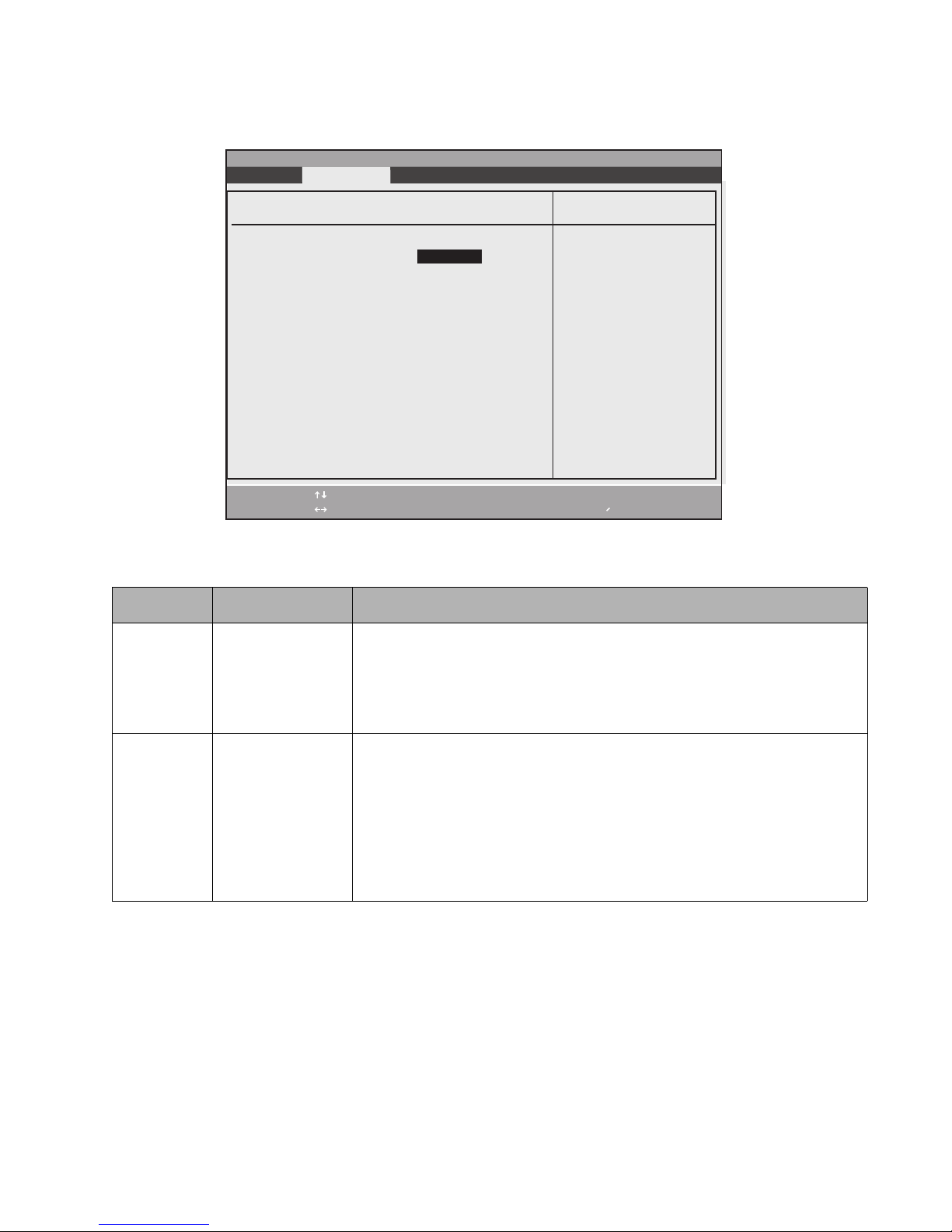
USB Features Submenu 2
Options for the USB Features submenu are given in Table 2-8.
PhoenixBIOS Setup Utility
Exit Submenu
USB Features
Legacy USB Support: [Enabled]
SCSI SubClass Support: [Enabled]
F1 Help
ESC Exit
Select Item
Select Menu
-/Space
Enter
Change Values
Select Sub-Menu
▲
Item Specific Help
[Disabled]
The feature is disabled.
[Enabled]
Legacy USB Emulation
is enabled and USB
devices are available
without USB aware OS.
F9 Setup Defaults
F10 Save and Exit
Table 2-9. USB Features Submenu Options
Option Settings Description
Legacy USB
Support:
Disabled
Enabled
This option enables or disables Legacy USB emulation.
When [Disabled] is selected, Legacy USB support is disabled.
When [Enabled] is selected, Legacy USB support is enabled, and certain USB
devices (such as CD-ROMs and keyboards) can be used without a USB-aware
operating system.
SCSI
SubClass
Support:
Disabled
Enabled
This option enables or disables support for USB devices that belong to the SCSI
subclass in the Mass Storage class (e.g., USB CD-ROM). Note that this option is
visible but disabled if Legacy USB Support is disabled.
When [Disabled] is selected, the feature is disabled.
When [Enabled] is selected, USB devices that belong to the SCSI subclass in the
Mass Storage class can be used. Note that enabling this feature could cause the
system to hang during POST, depending upon the device that is connected
BIOS Setup Utility 17
Page 22
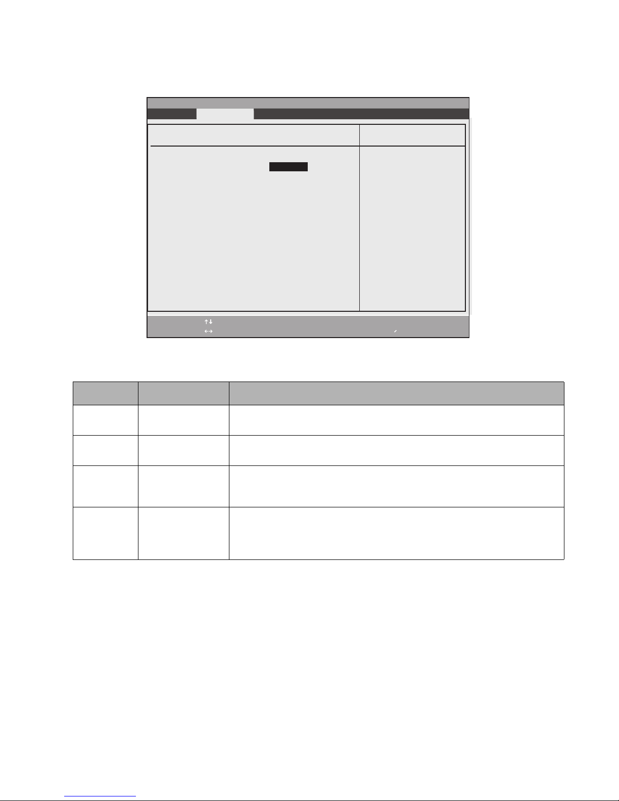
Miscellaneous Configurations Submenu 2
Options for the Miscellaneous Configurations submenu are given in Table 2-8.
PhoenixBIOS Setup Utility
Exit Submenu
Miscellaneous Configurations
Power Button: [Disabled]
Wake up on LAN: [Disabled]
Auto Save To Disk: [Off]
Volume Setting: [Middle]
F1 Help
ESC Exit
Select Item
Select Menu
-/Space
Enter
Change Values
Select Sub-Menu
▲
Item Specific Help
Configures the power
button.
*ACPI OS ignores this
setting.
F9 Setup Defaults
F10 Save and Exit
Table 2-10. Miscellaneous Configurations Submenu Options
Option Settings Description
Power
Button:
Disabled
Power Off
This option enables or disables the system power button. Note that an ACPI OS
overrides this setting.
Wake up on
LAN:
Auto Save To
Disk:
Volume
Setting:
Disabled
Enabled
Off
On
Off
Minimum
Middle
Maximum
Enabling this feature will cause the system to wake when the internal LAN receives
a Magic Packet while in the Power-Off state.
Turns on or off the Auto Save To Disk feature. When this is turned on, when the
battery enters low state and the system is in suspend mode, the system will save its
state to disk and power off automatically.
Allows you to disable the volume or adjust its level.
BIOS Setup Utility 18
Page 23
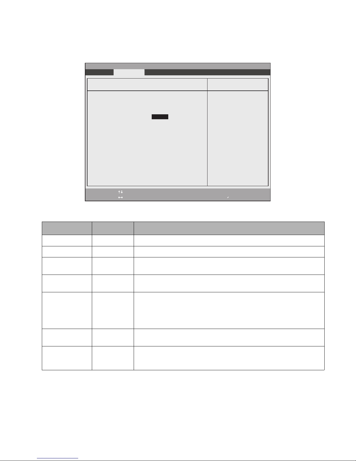
Event Logging Submenu 2
The Event Logging Submenu allows you to configure DMI (Desktop Management Interface) event logging options.
To access this submenu, select Event Logging Submenu from the Advanced menu.
PhoenixBIOS Setup Utility
Exit Submenu
Event Logging
Event Log Capacity: Space Available
Event Log Validity: Valid
View Event Log: [Enter]
Event Logging: [Enabled]
System Boot Event: [Disabled]
Clear All Event Logs: [No]
Mark Events as Read: [Enter]
F1 Help
ESC Exit
Select Item
Select Menu
-/Space
Enter
Change Values
▲
Select Sub-Menu
Item Specific Help
Press <Enter> key to
view the contents of
the event log.
F9 Setup Defaults
F10 Save and Exit
Table 2-11. Event Logging Submenu Options
Option Settings Description
Event Log Capacity ----- Status of the event log is displayed.
Event Log Validity ----- Indicates whether data in the event log is valid.
View Event Log Enter Press the <Enter> key or select the [Enter] option to view the contents of the
event log.
Event Logging Disabled
Determines whether DMI event logging is enabled.
Enabled
System Boot Event Disabled
This option is only available when [Enabled] is selected for Event Logging.
Enabled
When [Enabled] is selected, the event may be logged.
When [Disabled] is selected, the event is ignored.
Clear All Event
Logs
Mark Events as
Read
No
Yes
Choose [Yes] to clear all DMI event logs at the next boot. (This setting is reset to
No after the event logs are cleared.)
Enter Press [Enter] or press the <Enter> key to mark all events currently in the event log
as read. Marked events will not be displayed the next time View Event Log is
selected.
BIOS Setup Utility 19
Page 24
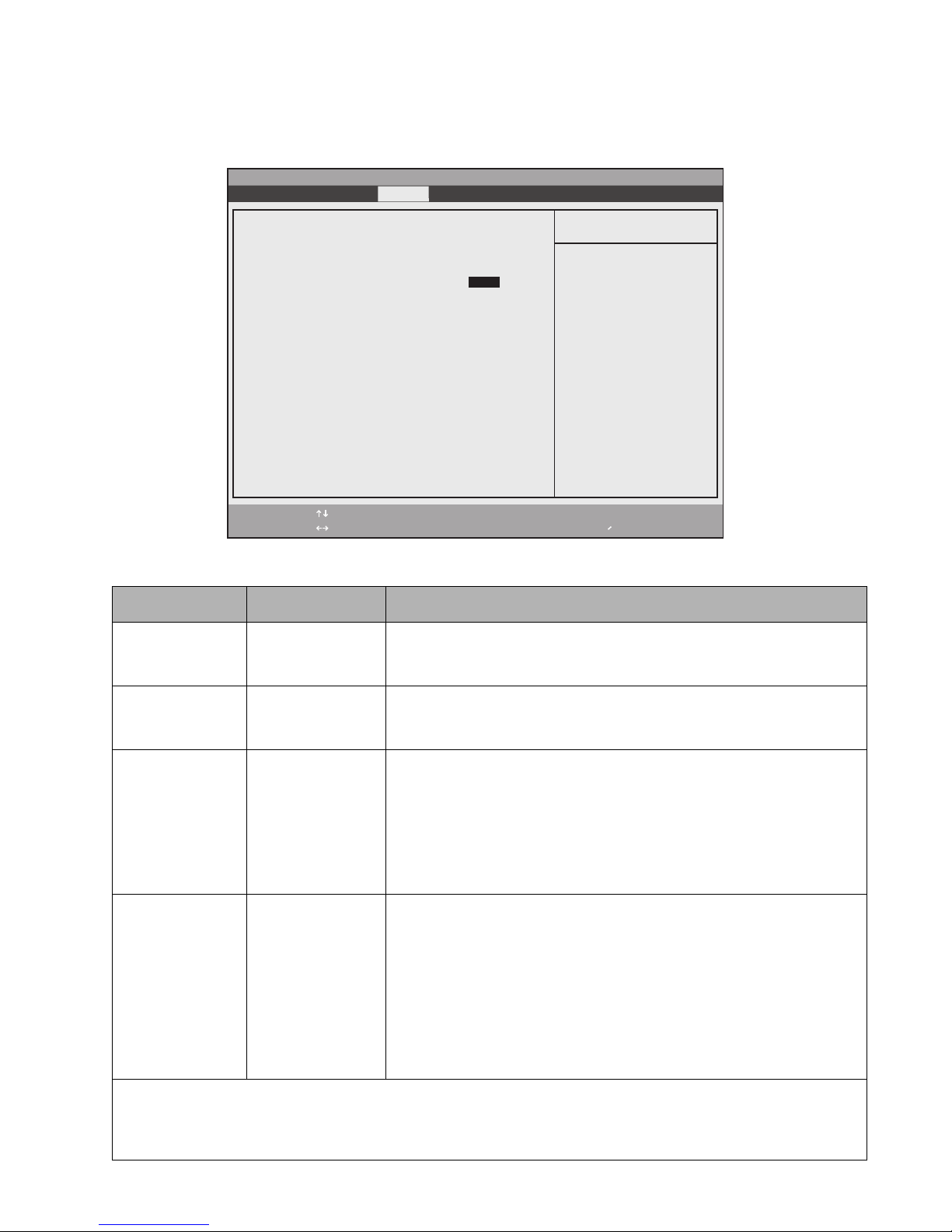
Security Menu Options 2
Security menu options for the Stylistic ST5000 Tablet PC are described in Table 2-12. Note that settings for some
security menu options determine whether other options are available.
PhoenixBIOS Setup Utility
Main Advanced Security Boot Info Exit
Supervisor Password Is: Clear
User Password Is: Clear
Set Supervisor Password [Enter]
Set User Password [Enter]
Minimum User Password Length: [0]
Password on Boot: [Disabled]
On Automatic Wake up: [Disabled]
▲ ▲
Boot from Removable Media: [All]
Hard Disk Security
Owner Information
Security Panel on Resume: [Enabled]
F1 Help
ESC Exit
Select Item
Select Menu
-/Space
Enter
Change Values
▲
Select Sub-Menu
Press [Enter] key to
set Supervisor Password
to enable any password
features.
Then password entry is
required to enter BIOS
Setup.
Table 2-12. BIOS Setup Security Menu Options
Option Settings Description
Supervisor
Password Is:
Set
Clear
Indicates whether a supervisor password has been specified. (This field cannot
be changed directly. To enable or disable the supervisor password, enter a
new password or clear the old one using the Set Supervisor Password option.)
Item Specific Help
F9 Setup Defaults
F10 Save and Exit
User Password Is: Set
Clear
Indicates whether a user password has been specified. (This field cannot be
changed directly. To enable or disable the user password, enter a new
password or clear the old password using the Set User Password option.)
Set Supervisor
Password*
(Tap on the setting
field for this option
or press the
<Enter> key to
specify a supervisor
password.)
Specifying a supervisor password grants access to all password protected
Security menu options.
When a supervisor password is enabled and a user password is used to enter
BIOS Setup, the user cannot access the following Security menu options: Set
Supervisor Password, Floppy Disk Access, and Hard Disk Boot Sector.
When enabled, a supervisor password (or user password if used) is required
to run BIOS Setup.
Set User
Password*
(Tap on the setting
field for this option
or press the
<Enter> key to
specify a user
password.)
Specifying a user password grants access to the following Security menu
options only: User Password, Password On Boot. Other Security menu
options are not accessible.
(When a supervisor password is enabled and a user password is used to enter
BIOS Setup, the user cannot access the following Security options: Set
Supervisor Password, Floppy Disk Access, Hard Disk Boot Sector.)
When enabled, a user (or supervisor) password is required to run BIOS Setup.
Note that a supervisor password must be enabled before a user password can
be specified.
* When both the Supervisor and User passwords are set, and a User password is used to enter the BIOS, the following
Menu items can be changed: Main -> Language, Advanced -> Video Features -> Display, Advanced -> CPU Features -> (all
items), Advanced -> Miscellaneous Configurations -> (all items), Advanced -> Events Logging -> View Event Log, Security
-> Set User Password, Exit -> Exit Saving Changes, Exit -> Exit Discarding Changes, Exit -> Save Changes.
BIOS Setup Utility 20
Page 25
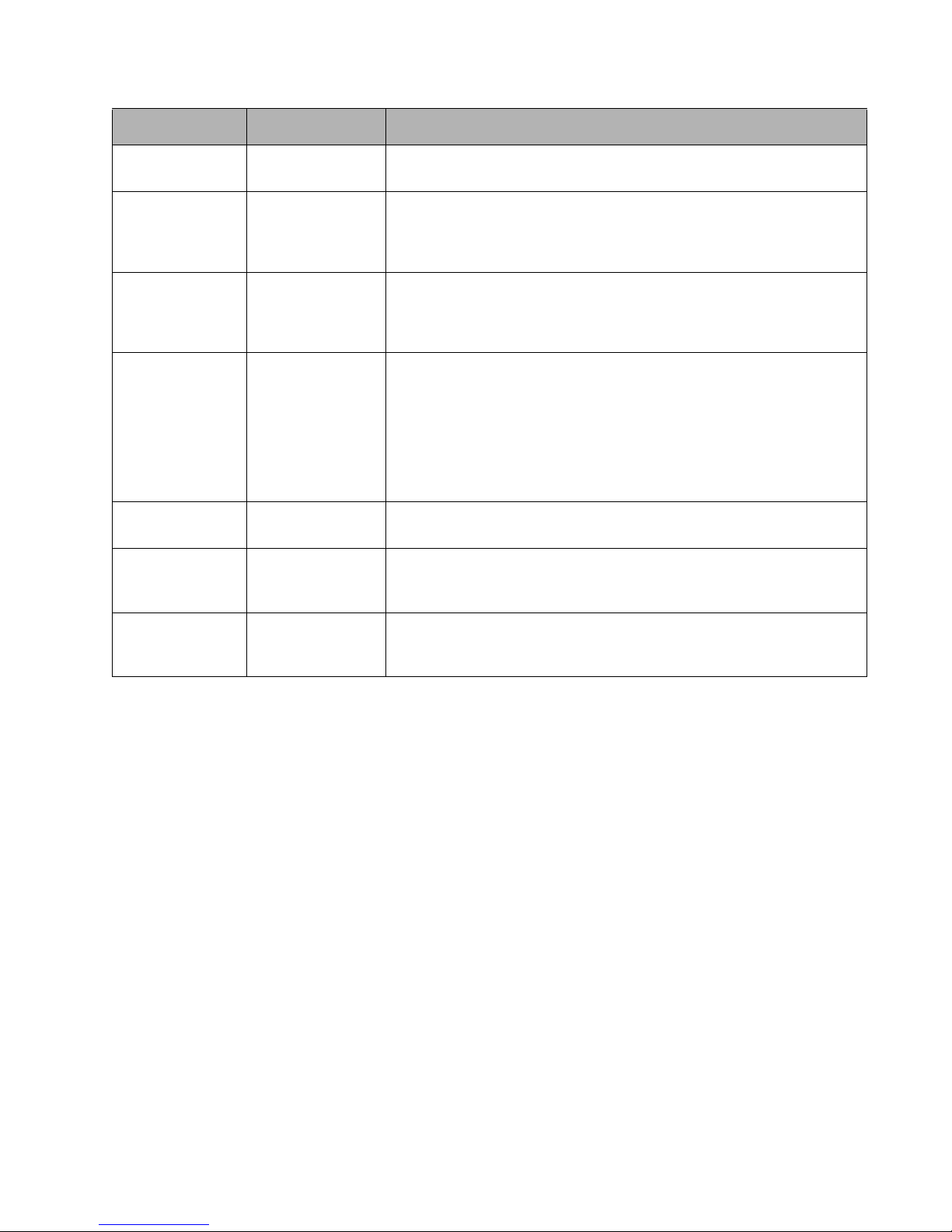
Table 2-12. BIOS Setup Security Menu Options (Continued)
Option Settings Description
Minimum User
[0] Set the minimum length for the user password. Once this field is set, the user
Password Length:
Password On Boot: Disabled
First Boot
Every Boot
On Automatic
Wake up:
Boot from
Removable Media:
Hard Disk Security
Disabled
Enabled
All
Supervisor Only
____ Enter this submenu to change hard disk security. (See “Hard Disk Security
Submenu
Owner
____ Enter this submenu to change owner information. (See “Owner Information
Information
Submenu
cannot enter any passwords less than the minimum length.
Select [First Boot] to require a user or supervisor password to boot the system
the first time. Select [Every Boot] to require a user or supervisor password to
boot the system every time the system is booted. Note that a user or
supervisor password must be specified before this option can be enabled.
This feature is only available when Password on Boot: is enabled.
When enabled, password entry is required on automatic wake up by LAN or
RTC. When disabled, password entry is not required on automatic wake up
by LAN or RTC.
This option determines who has permission to boot the system using
removable media. Select [Supervisor Only] to allow the system only to be
booted from removable media after the system is started by entering a
supervisor password when the Password On Boot option is enabled.
When [Supervisor Only] is selected, the system cannot be booted from
removable media if Supervisor Password is enabled and the Supervisor
password was not entered at boot time.
Submenu” on page 22 for details).
Submenu” on page 23 for details).
Security Panel on
Resume:
Disabled
Enabled
When enabled, the Security Panel feature is enabled upon Resume from
Suspend. When disabled, the Security Panel feature is disabled upon Resume
from Suspend.
BIOS Setup Utility 21
Page 26
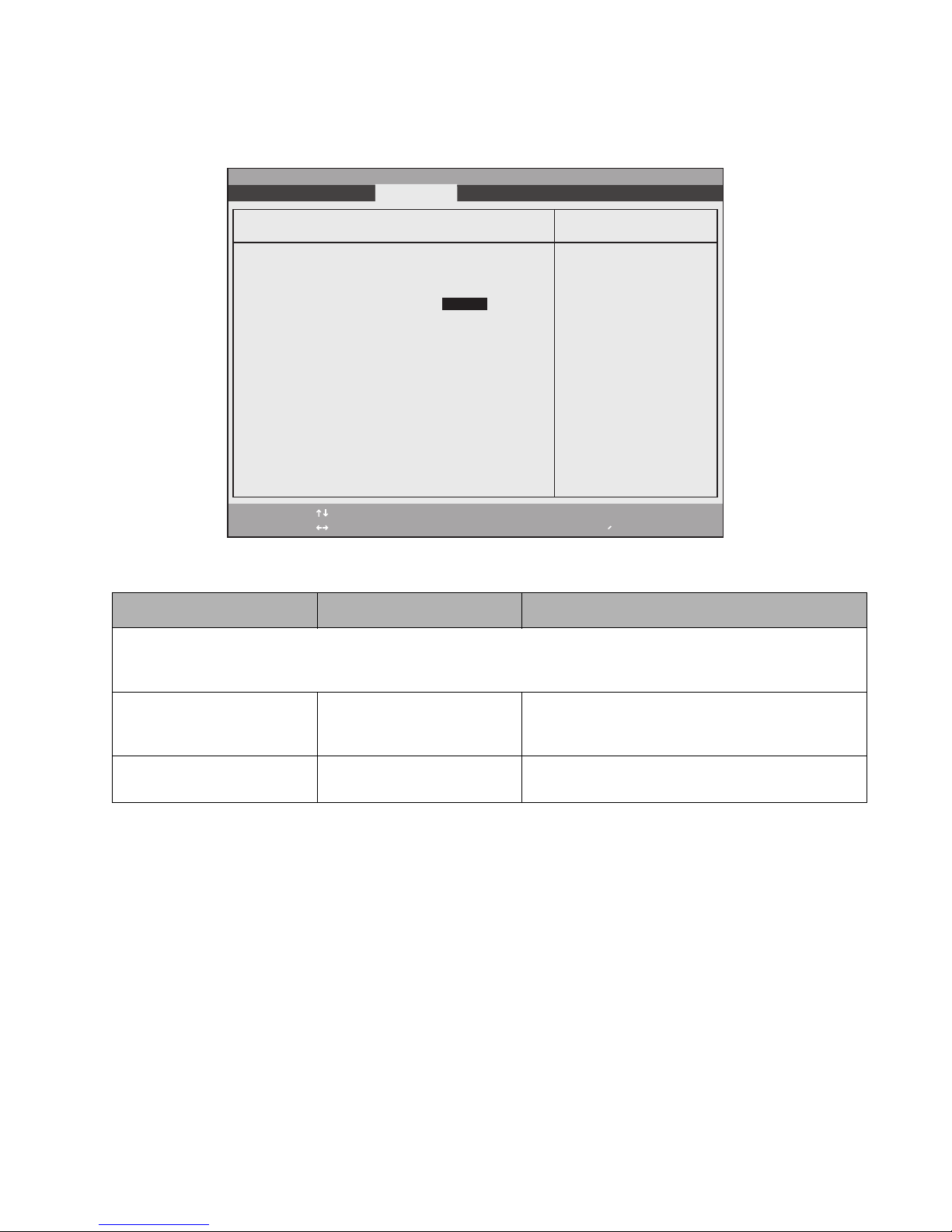
Hard Disk Security Submenu 2
The Hard Disk Security Submenu allows you to enable or disable the Primary Master device. To access this
submenu, select Hard Disk Security from the Security menu.
PhoenixBIOS Setup Utility
Main Advanced Exit Submenu Power Savings Exit
Hard Disk Security
Primary Master Password Is: Clear
Set Primary Master Password [Enter]
F1 Help
ESC Exit
Select Item
Select Menu
-/Space
Enter
Change Values
▲
Select Sub-Menu
Item Specific Help
Press <Enter> key to
set Hard Disk Password.
The hard disk is locked
with the password. Data
in the locked disk can
not be read on other
systems.
F9 Setup Defaults
F10 Save and Exit
Table 2-13. Hard Disk Security Submenu Options
Option Settings Description
Note that when a Primary Master Password is set for a hard disk drive, the hard disk drive will only function in a system that
has the same hard disk drive password. If the drive is put into another system with no password or with a different
password, the hard disk drive will not work. Note, however, that the data on the drive is not encrypted.
Primary Master Password Is: Clear Display only. Either Clear or Set, depending upon
whether a Primary Master Password is entered in the
following field.
Set Primary Master Password ----- Allows you to enter a master password when a
supervisor password has been set.
BIOS Setup Utility 22
Page 27
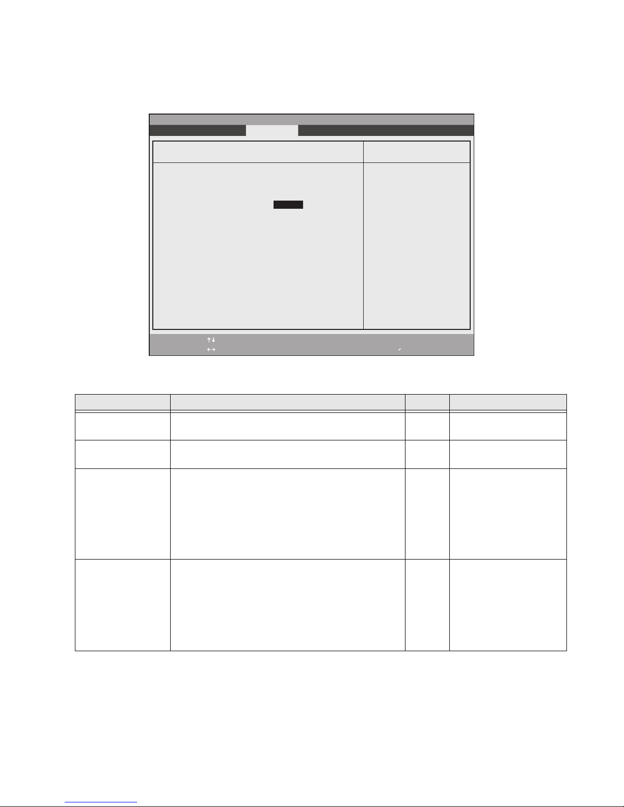
Owner Information Submenu 2
The Owner Information Submenu allows you to enter information about the owner and to change the foreground
and background colors. To access this submenu, select Owner Information from the Security menu.
PhoenixBIOS Setup Utility
Exit Submenu
Owner Information
Owner Information Is: Clear
Set Owner Information [Enter]
Foreground Color: [Gray]
Background Color: [Black]
F1 Help
ESC Exit
Select Item
Select Menu
-/Space
Enter
Change Values
▲
Select Sub-Menu
Item Specific Help
F9 Setup Defaults
F10 Save and Exit
Table 2-14. Owner Information Submenu Options
Menu Field Options Default Description
Owner Information
Is:
–— Clear Display only.
Set Owner
–— [Enter] Field to write owner
Information:
Foreground Color: • Black
•Blue
• Green
• Cyan
•Red
• Magenta
Background Color: • Black
•Blue
• Green
• Cyan
•Red
• Magenta
•Brown
•White
•Gray
• Light Blue
• Light Green
•Brown
•White
•Gray
• Light Blue
• Light Green
• Light Cyan
•Light Red
• Light Magenta
• Yellow
• Bright White
• Light Cyan
•Light Red
• Light Magenta
• Yellow
• Bright White
information (e.g., name).
[Gray] Select a color for the
foreground.
[Black] Select a color for the
background.
BIOS Setup Utility 23
Page 28
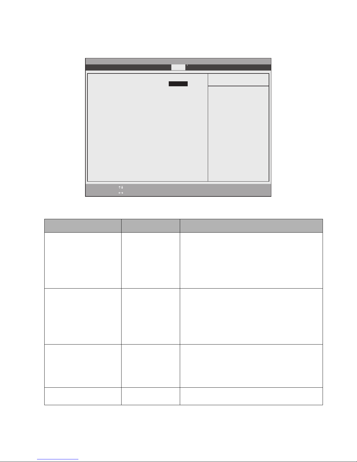
Boot Menu Options 2
Boot menu options are described in Table 2-15.
PhoenixBIOS Setup Utility
Main Advanced Security Boot Info Exit
Quick Boot: [Enabled]
Boot Time Diagnostic Screen: [Disabled]
▲
Preboot Execution Environment: [Disabled]
Boot Device Priority
F1 Help
ESC Exit
Select Item
Select Menu
Table 2-15. BIOS Setup Boot Menu Options
Option Settings Description
QuickBoot Disabled
Enabled
-/Space
Enter
Item Specific Help
[Disabled]
All diagnostic tests
will be done.
[Enabled]
Some diagnostic tests
may be skipped while
booting to speed up.
Change Values
▲
Select Sub-Menu
F9 Setup Defaults
F10 Save and Exit
Determines whether the full set of tests are run during the
Power-On Self Test (POST).
When [Enabled] is selected, a less extensive memory test is
performed and the size of installed memory is not displayed
during the memory test.
When [Disabled] is selected, the full set of tests is run.
Boot Time Diagnostic Screen Disabled
Enabled
Determines whether status messages are displayed as the
Power On Self Test (POST) is performed.
Select [Enabled] to display messages.
If [Disabled] is selected, messages are not displayed and the
logo screen is displayed. (If POST errors occur, POST
messages are displayed regardless of this setting.)
Preboot Execution
Environment
Disabled
Enabled
Determines whether to boot up from a network server.
Select [Enabled] to allow the system to boot from a network
server (Preboot Execution Environment).
If [Disabled] is selected, this feature is disabled.
Boot Device Priority Submenu Select this submenu to configure the order in which drives
are searched for a bootable image.
BIOS Setup Utility 24
Page 29
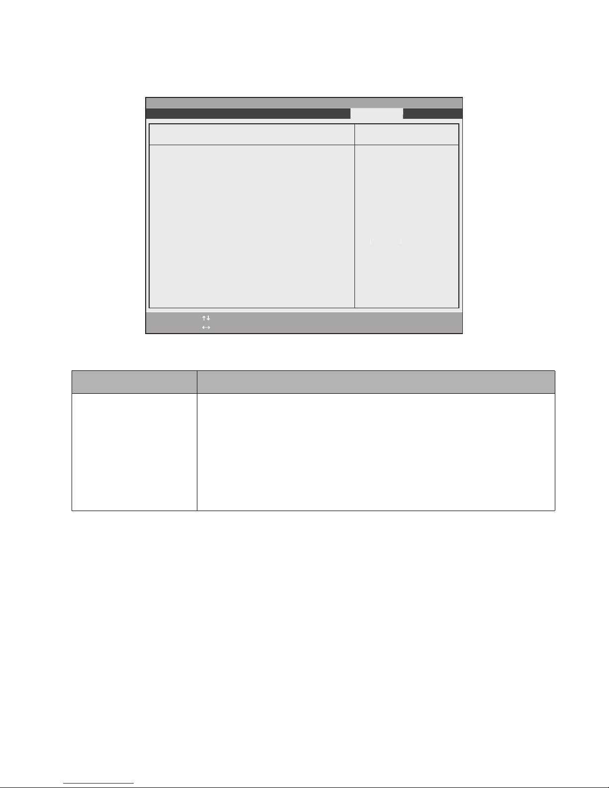
Boot Device Priority Submenu 2
Table 2-16. describes settings in the Boot Device Priority submenu.
PhoenixBIOS Setup Utility
Exit Submenu
Setting Description
Floppy Disk Drive
Boot Device Priority
Floppy Disk Drive
+Hard Disk Drive
Optical Media Drive
F1 Help
ESC Exit
Select Item
Select Menu
Table 2-16. BIOS Setup Boot Sequence Submenu
Determines the order in which the system searches drives for a bootable image.
-/Space
Enter
Keys used to view or
configure devices:
<Enter> expands or
collapses devices with
a + or -.
<Ctrl+Enter> expands
all.
<Shift+1> enables or
disables a device.
<+>/<Space> or <->
moves the device up or
down.
<d> removes a device
that is not installed.
Change Values
▲
Select Sub-Menu
Item Specific Help
F9 Setup Defaults
F10 Save and Exit
+Hard Disk Drive
Optical Media Drive
Tap on an item which appears below another to move it up in the list to change the boot
sequence. (e.g., in the example above, to move Hard Disk Drive down, you must tap
Optical Media Drive to move it above Hard Disk Drive.)
If you click on the pen barrel button while tapping an item, the item will move down the
list.
If there is a “+” next to an item, tap the item then press the [Ent] key to expand the list.
BIOS Setup Utility 25
Page 30
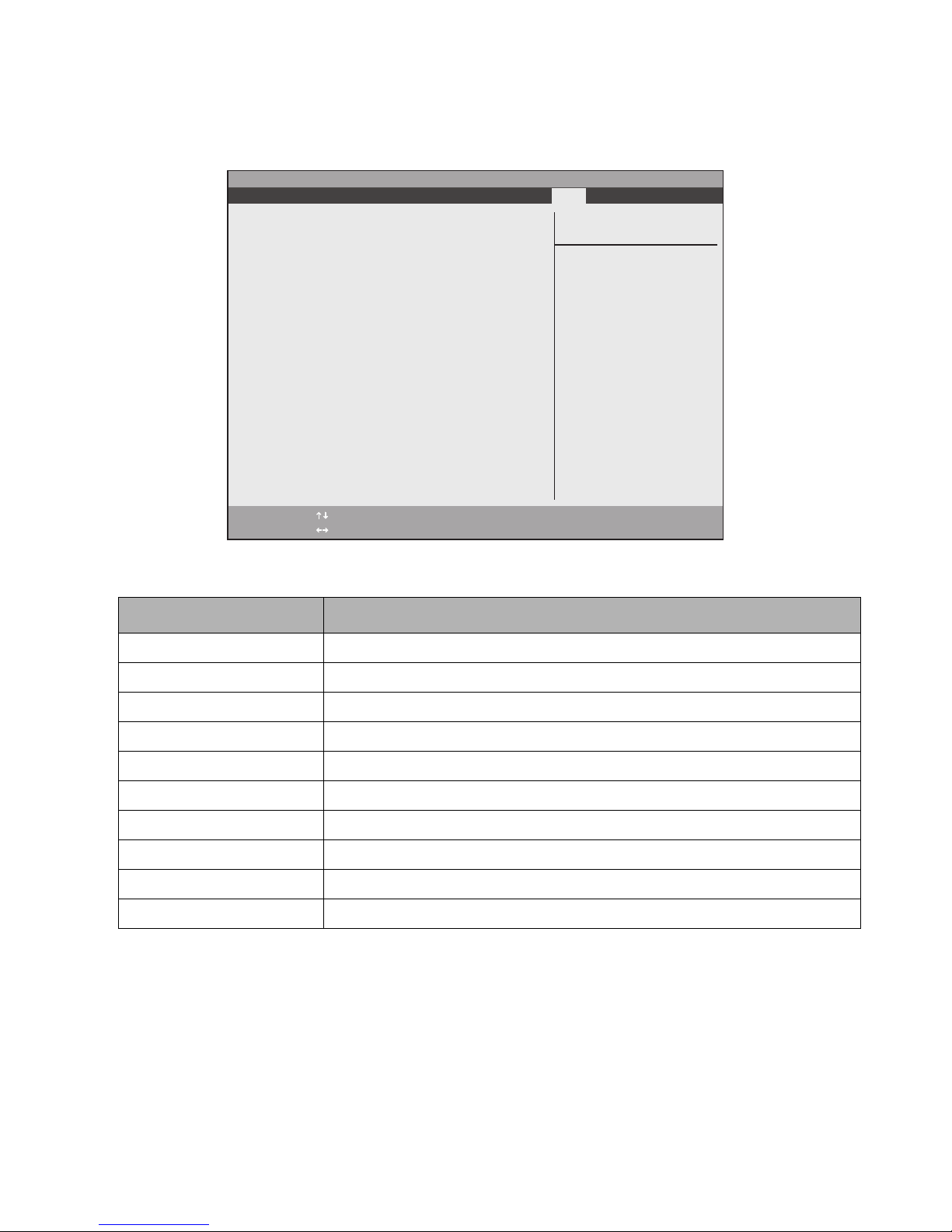
Info Menu 2
The Info menu displays information about the Tablet PC hardware and BIOS software installed on the system as
described in Table 2-17.
PhoenixBIOS Setup Utility
Main Advanced Security Boot Exit
Info
BIOS Version: 1.04
BIOS Date: 12/09/2003
BIOS Area: E000h - FFFFh
CPU Type: ULV Intel(R) Pentium(R) M
CPU Speed: 1.00 GHz
L1 Cache: 64 KB
L2 Cache: 1024 KB
Total Memory: 512 MB
Memory Slot 1: 512 MB DDR SDRAM
Memory Slot 2: None
F1 Help
ESC Exit
Select Item
Select Menu
-/Space Change Values
Enter Select Sub-Menu
▲
Item Specific Help
F9 Setup Defaults
F10 Save and Exit
Table 2-17. BIOS Setup Info Menu
Field Description
BIOS Version: Version number of the BIOS software installed on system.
BIOS Date: Release date of the BIOS software.
BIOS Area: Memory area used by the BIOS.
CPU Type: CPU type used.
CPU Speed: Processor speed.
L1 Cache: Size of CPU level 1 cache.
L2 Cache: Size of CPU level 2 cache.
Total Memory: Total memory installed in Tablet PC (including built-in memory).
Memory Slot 1: Total memory installed in memory slot 1.
Memory Slot 2: Total memory installed in memory slot 2.
BIOS Setup Utility 26
Page 31
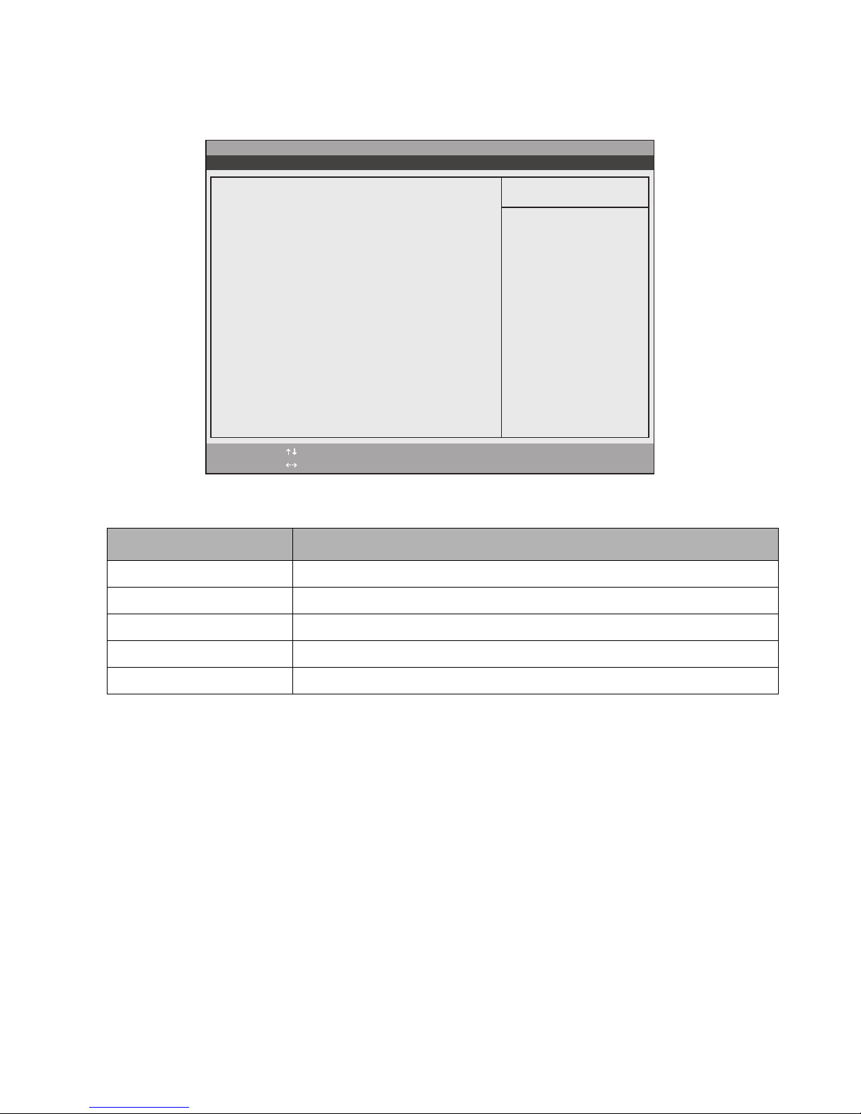
Exit Menu Options 2
Exit menu options are described in Table 2-18.
PhoenixBIOS Setup Utility
Main Advanced Security Power Boot Info Exit
Exit Saving Changes
Exit Discarding Changes
Load Setup Defaults
Discard Changes
Save Changes
F1 Help
ESC Exit
Select Item
Select Menu
-/Space Change Values
Enter Select Sub-Menu
▲
Item Specific Help
Exit System Setup and
save your changes to
CMOS.
F9 Setup Defaults
F10 Save and Exit
Table 2-18. BIOS Setup Exit Menu Options
Option Description
Exit Saving Changes Exit after writing all changed BIOS Setup settings to CMOS memory.
Exit Discarding Changes Exit without saving changes to BIOS Setup settings to CMOS memory.
Load Setup Defaults Load default settings for all BIOS Setup options.
Discard Changes Read previous settings from CMOS memory and load in all BIOS Setup options.
Save Changes Save BIOS changes to CMOS.
BIOS Setup Utility 27
Page 32
Chapter 3
Hardware Specifications
Specifications for the Stylistic ST5000 Tablet PC and Tablet Dock are given in this chapter.
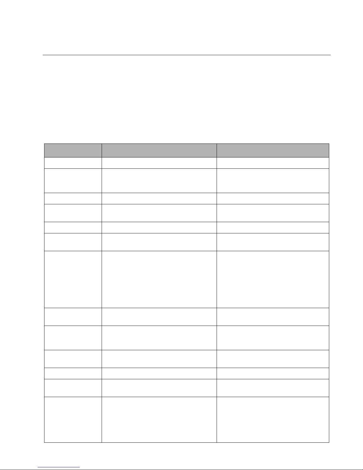
General Specifications 3
General specifications for the Tablet PC are given in Table 3-1.
Table 3-1. General System Specifications
Feature Specification Comments
Architecture IBM-AT compatible
Microprocessor 1.0 GHz ultra-low voltage (ULV) Mobile Intel®
Pentium® processor - M with SpeedStep®
technology
Chipset Intel 855GME
Cache Level 1 (L1) cache: 64 KB
Level 2 (L2) cache: 1024 KB
BIOS ROM 2 MB Firmware Hub (FWH)
RAM (expansion) Two 200-pin DIMM slots.
Supports up to 2 GB memory.
Video Memory Intel 855GME chipset with 8 MB shared
memory using UMA and DVMT.
I/O Controller LPC47N217
Standard Microsystems Corporation
PC Card Controller OZ711M3 Controller is on PCI bus. Supports CardBus
Audio Controller Intel ICH4-M AC’07 controller with Realtek
ALC202 Codec
IEEE 1394 Controller NEC uPD72873
L1 and L2 caches are always enabled.
Total allowable RAM is 2 GB. (1 GB installed,
plus up to 1 GB in slot)
Unified Memory Architecture (UMA) delivers
low-power, high-performance 3D/2D
graphics, video, and display capabilities.
Dynamic Video Memory Technology (DVMT)
responds dynamically to application
requirements and allocates the proper amount
of memory (64 MB max.) for optimal graphics
and system performance.
Controller for IrDA and communication with
Tablet Controller.
(PCI bridge) and PCIC protocols. The
controller does not support Zoomed Video.
Modem Chipset Agere Systems CSP1037 AC-Link Soft Modem
Chipset
Hard Disk Drive • IDE
• Shock-mounted
• ATA 100
• Smart Support
• 4200 rpm
Capacity is either 40 GB or 60 GB, depending
upon configuration.
28
Page 33
Digitizer Specifications 3
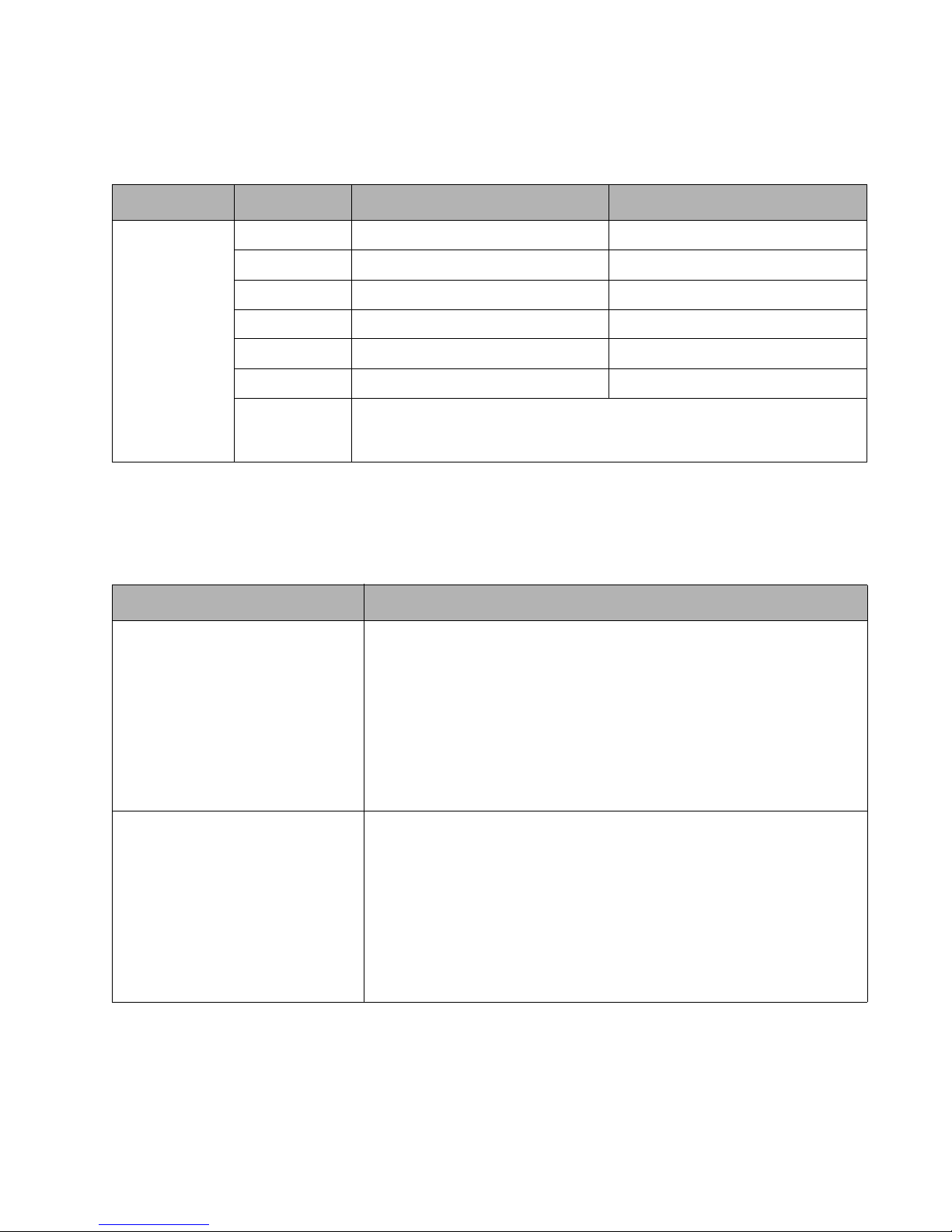
Specifications for the two different Stylistic ST5000 Tablet PC digitizers are given in Table 3-2..
Table 3-2. Digitizer Specifications
Feature Feature Sensor Unit for 12.1” LCD Sensor Unit for 10.4” LCD
Active Digitizer Type Electromagnetic digitizer Electromagnetic digitizer
Area 9.75” x 7.33” (247.8 mm x 186.3 mm) 9.26” x 5.8” (235.3 mm x 147.4 mm)
Resolution 0.01 mm 0.025 mm
Sampling Rate 133 pps 133 pps
Interface Serial interface Serial interface
Vendor Wacom Wacom
Pen Weight: 0.53 oz. (15g)
Size: 5.51” (length) x 0.35” (diameter) (140 mm x 9 mm)
Vendor: Wacom
Display Specifications 3
Specifications for the Stylistic ST5000 Tablet PC display are given in Table 3-3.
Table 3-3. Display Specifications
Feature Specification
Transmissive XGA LCD • 12.1" diagonal TFT Color
• XGA 1024 x 768 dot composition
• Aspect ratio: 4:3
• Transmissive
• 260K colors
• Active area: 9.67” x 7.25” (245.76 mm x 184.32 mm)
• Brightness: 8 gradations
• Frontlight: FL Tube; brightness: ~20-150 Cd/m
Reflective XGA LCD • 10.4" diagonal TFT Color
• XGA 1024 x 768 dot composition
• Aspect ratio: 4:3
• Reflective
• 260K colors
• Active area: 8.28” x 6.21” (210.43 mm x 157.82 mm)
• Brightness: 8 gradations
• Frontlight: FL Tube; brightness: ~0 - 45 Cd/m
2
2
Digitizer Specifications 29
Page 34
External Video Capabilities 3
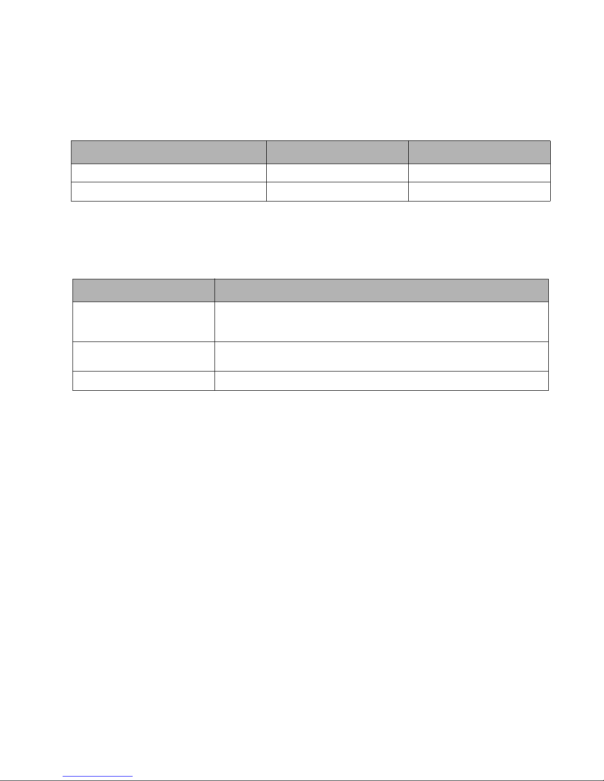
The Stylistic ST5000 Tablet PC Tablet Dock can drive an external video monitor. You can select an external monitor,
the Tablet PC display screen, or both as the active video display. The Tablet PC supports VGA, SVGA, and XGA
video modes with external monitors. Screen resolutions supported are given in Table 3-4.
Table 3-4. Supported Video Modes for External Monitors
Video Configuration Resolution Colors
CRT only Max. 1600 x 1200 Up to 16 M
Simultaneous Max. 1024 x 768 Up to 16 M
Environmental Specifications 3
Environmental specifications for the Stylistic ST5000 Tablet PC are given in Table 3-5.
Table 3-5. Environmental Specifications
Feature Specification
Temperature
Humidity Operating: 20% to 80% RH noncondensing
Vibration 0.67G, random
Operating: 41° to 95°F (5° to 35°C)
Nonoperating: 5° to 140°F (-15° to 60°C)
(with appropriate power management)
Nonoperating: 20% to 80% RH noncondensing
External Video Capabilities 30
Page 35

Peripheral Interface Specifications 3
Specifications for peripheral interfaces on the Tablet PC are given in Table 3-6. For specifications on peripheral
interfaces provided by the Tablet Dock, see “Tablet Dock Specifications” later in this chapter. Also note that pin
assignments and other details for peripheral interfaces on the Stylistic ST5000 Tablet PC are given in Chapter 4.
Table 3-6. Peripheral Interface Specifications
Feature Specification Comments
PC Card Slot One Type II PCMCIA CardBus slot.
Compliant with PC Card Standard Rev. 3.0
IDE Interface Supports one IDE hard drive (2.5 inch) IDE hard drive is preinstalled at factory.
Modem Port RJ-11 connector for internal modem See “Internal Modem Specifications” on page
LAN Port RJ-45 connector for internal LAN. See “Internal LAN Specifications” on page 34
External Monitor Port Analog RGB mini D-Sub 15-pin connector that
allows you to connect an external monitor.
Universal Serial Bus
Port (USB A) 2.0
IrDA Port Infrared transceiver built into Tablet PC. Compliant with IrDA Standard Revision 1.1
Smart Card Slot Dedicated Smart Card slot
SD/Memory Stick Slot Secure Digital/Memory Stick slot
Two (2) USB 2.0 Series A receptacles on Tablet
PC.
Supports CardBus and PCIC (PC Card I/O
Cards)
34 for more information.
for more information.
See Table 3-4, “Supported Video Modes for
External Monitors,” on page 30 for more
details.
Supports: FIR (4 Mbps max),
SIR (115 Kbps max)
Range: approximately 1 M, 15 degrees from
center
Infrared Keyboard
Ports
DC Power Input 16 VDC ±10%, 3.75 A
Audio Jacks Mono microphone input mini jack
IEEE 1394 Jack S400, 4-pin connector
System Interface Port 100-pin connector For use with Stylistic ST5000 Tablet Dock.
Infrared receivers built into the Tablet PC for
use with an optional infrared keyboard or
mouse.
Connector vendor: Hosiden (Hosiden part
number HEC3900-01-010) This connector is a
EIAJ-RC5320A standard connector.
Stereo headphone output mini jack
Proprietary Fujitsu receivers.
Range: approximately 1 M, 15 degrees from
center
External power can be connected to DC input
connector on the Tablet PC or Tablet Dock.
See “DC Power Inputs” on page 49 for more
details.
Standard 3.5 mm mini jacks.
See “Audio Jacks” on page 42 for details on
audio inputs and outputs.
Peripheral Interface Specifications 31
Page 36
Physical Specifications 3
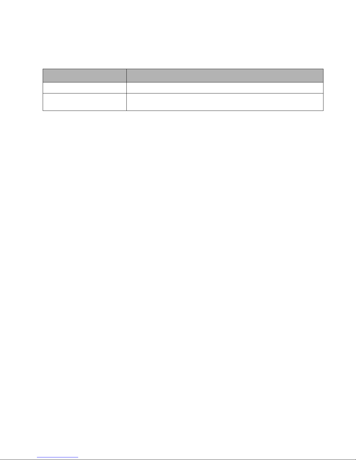
Physical specifications for the Stylistic ST5000 Tablet PC are given in Table 3-7.
Table 3-7. Stylistic ST5000 Tablet PC Specifications
Feature Specification
Tablet PC Dimensions 8.66” (w) x 12.77” (d) x 0.82/0.88” (h) (220 mm x 324.4 mm x 20.9/22.3mm)
Tablet PC Weight
(with battery pack)
3.4 lbs. (1.54 Kg)
Physical Specifications 32
Page 37
Power System Specifications 3
Specifications for the Stylistic ST5000 Tablet PC power system are given in Table 3-8. The power system and power
management characteristics are further described in Chapter 5 of this manual.
Table 3-8. Power System Specifications
Feature Specification Comments
Power Management
ACPI Specification Revision 1.0
Standard Supported
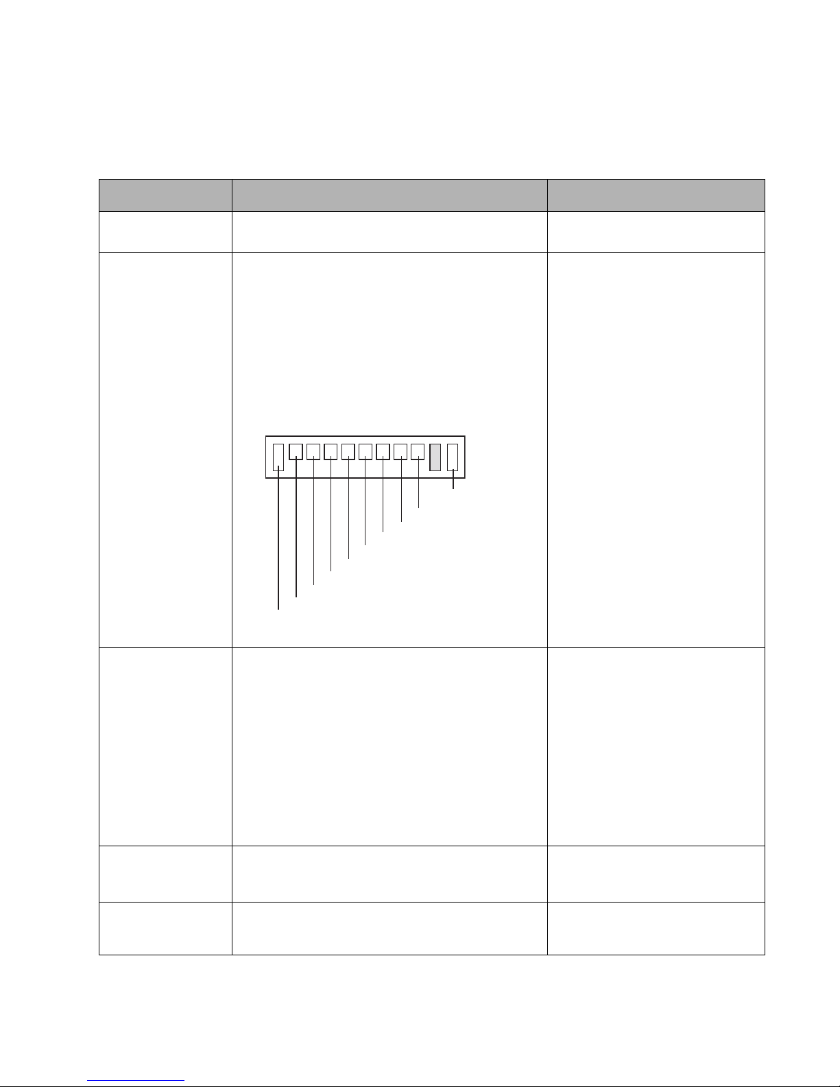
Battery Pack • Rechargeable 6-cell lithium ion battery pack
• Capacity: 4400 mAh
• Nominal operating voltage: 10.8 V
•Charge time:
Approximately 240 minutes (90% charge), 300
minutes (100% charge)
• Size: 218.2 5 mm (w) x 50.9 mm (d) x 22.3 mm (h)
• Weight: Approximately 330g
• Contact layout:
GND1
GNDA
ESDA1
ESCL1
BT1ID
BT1IN
BATTM+
SCONT1
VSENSE1
BATT1
Charge times are for a 0% charged
battery pack charging in Tablet PC
(not in an external battery charger).
If the battery pack charge is 90% or
higher when you connect DC power,
the battery pack will not charge, thus
preventing overcharging. Battery life
values are approximate.
Bridge Battery • Nickel metal hydride
•6 cells
• Capacity: 6.0 V, 35 mAH (210 mWh)
• Suspend life (backup battery only): Approximately 5
minutes
• Charge Time: 100 hours (with AC)
Sub Battery • Lithium battery (built in)
•210 mAh
AC Adapter • Input: 100-240 VAC, 50/60 Hz
• Output: 16 VDC ±10%, 3.75 A
Bridge battery supplies power to RAM
in suspend mode for about 5 minutes
while battery pack is removed.
Bridge battery is charged:
• In all modes when external DC
power is connected.
• In On, Idle, or Standby modes
(when system is running) when
external DC power is not
connected.
Provides real time clock power
backup. Approximate battery life is 5
years. (Not field replaceable.)
Power System Specifications 33
Page 38
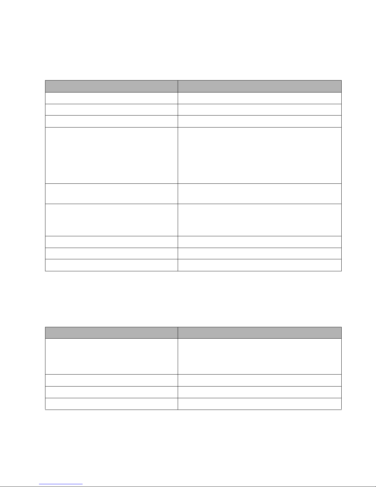
Internal Modem Specifications 3
The internal modem device connects to the system’s PCI bus. Specifications for the internal modem are given in
Table 3-9. The internal modem is built-in and is not field replaceable.
Table 3-9. Internal Modem Specifications
Feature Specification
Interface AC97 I/F Secondary Codec
Size 45 mm (w) x 27.6 mm (d) x 5.2 mm (h)
Chip Agere Systems CSP1037 AC-Link Soft Modem Chipset
Data Mode Capability • ITU-T V.90
•ITU-T V92
• ITU-T V.34 extended rate, V32bis, V32, V22bis
• TIA/EIA 602 standard for AT command set
• V.42 error correction
• V.42bis and MNP Class 5 data compression
Fax Mode Capability • ITU-T V17, V29, V27ter, V21 ch2
• TIA/EIA 578 Class 1 Fax
Support Countries USA, Canada, Japan, Singapore, Malaysia, Australia, New
Zealand, UK, France Germany, Finland, Sweden, Norway,
Portugal, Spain, Italy, Belgium, Greece, Austria, Denmark, Ireland,
Luxembourg, Netherlands, Switzerland
Supply Voltage 3.3v
Storage Humidity 80% RH
Manufacturer Fujitsu Media Devices
Internal LAN Specifications 3
The internal LAN device connects to the system’s PCI bus. Specifications for the internal modem are given in Table
3-10. The internal modem is built-in and is not field replaceable.
Table 3-10. Internal LAN Specifications
Feature Specification
Bus Connection • PCI
• Internal wired 10Base-T/100Base-Tx/1000* Base-T/Tx
Ethernet LAN.
*1000 Mbps, commonly referred to as Gigabit Ethernet.
Location On-board
Chip BCM5788 (Broadcom)
Additional Features Wake On LAN support
Internal Modem Specifications 34
Page 39
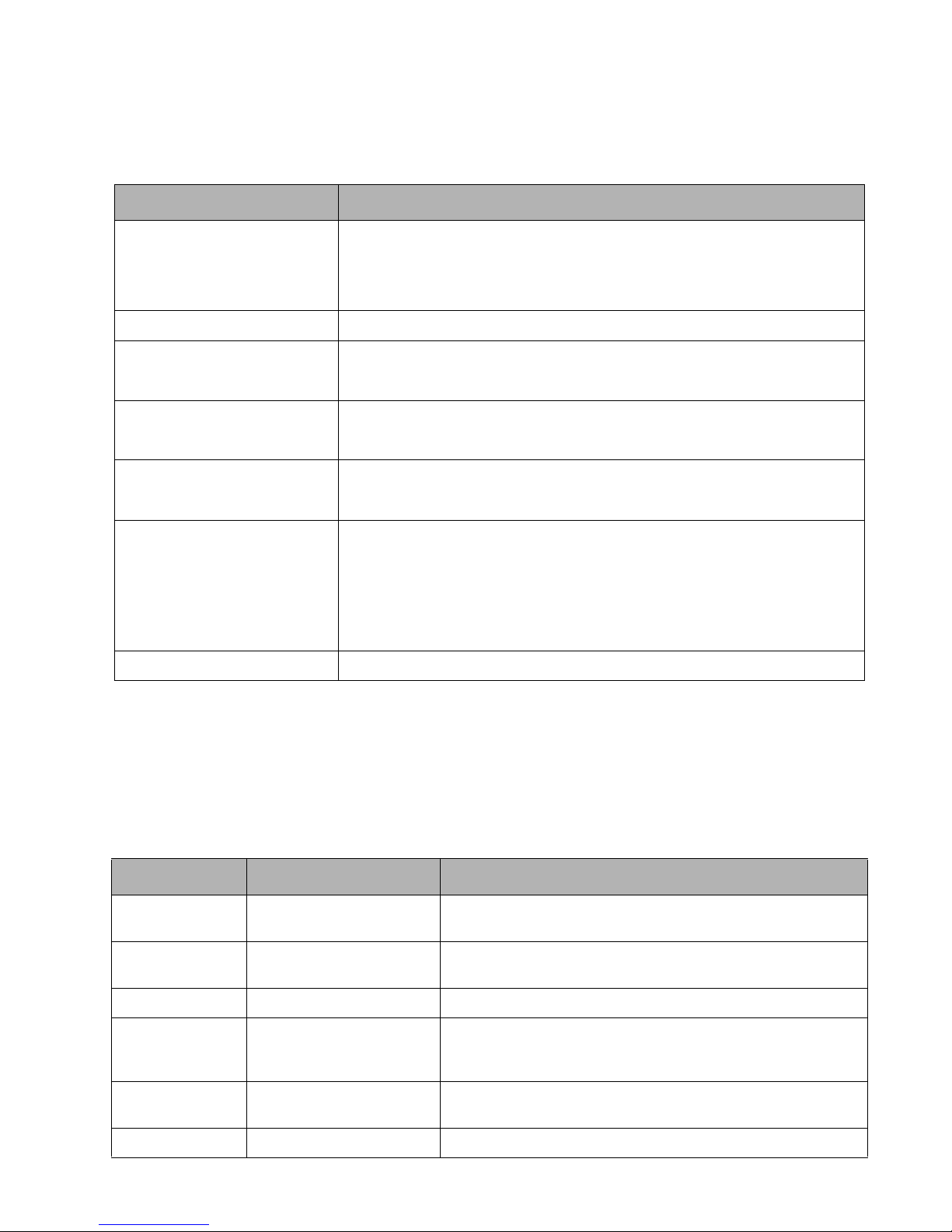
Agency Approval Specifications 3
Specifications for government agency approvals are given in Table 3-11.
Table 3-11. Agency Approval Specifications
Feature Specification
Emissions • FCC Part 15, Class B
• EN55022 (CISPR22) Class B
• VCCI Class B
Immunity • EN55024 (1998)
Safety • UL and cUL Listed, UL 60950, 3rd edition
• CB Report, IEC 60950, 3rd edition
Telecom • FCC Part 68
•IC CS-03
Specific Absorption Rate (SAR) • FCC/RSS
• ACA/EN
Wireless • EN300328
• EN301489
• EN301893
• FCC 15E
• RSS210
• RSS220
Other • Energy Star
Tablet Dock Specifications 3
The Stylistic ST5000 Tablet Dock is designed to provide optimal support for your Tablet PC. Specifications for
interfaces on the Stylistic ST5000 Tablet Dock are given in Table 3-12. Note that these interfaces duplicate
corresponding ports on the Tablet PC. For details on peripheral interfaces provided by the Tablet Dock, refer to
Chapter 4 of this manual.
Table 3-12. Stylistic ST5000 Tablet Dock Specifications
Feature Specification Comments
DC power input + tip / - sleeve
16 VDC ±10%, 3.75 A
External Monitor
(VGA) Port
LAN Port Standard RJ-45 port See “Internal LAN Specifications” on page 34 for more information.
Line Output Jack 3.5 mm mini stereo jack Using the line output jack does not disable any other audio features
Universal Serial Bus
2.0 Ports
Standard 15-pin video
connector
Three (3) USB Series A
receptacles
See “DC Power Input Connector Pin Assignments” on page 36 for
more details.
System supports simultaneous operation of external monitor with
LCD.
on the Tablet PC or Tablet Dock. (The line output jack is not disabled
when other audio jacks are used.)
IEEE 1394 Port S400, 4-pin
Agency Approval Specifications 35
Page 40
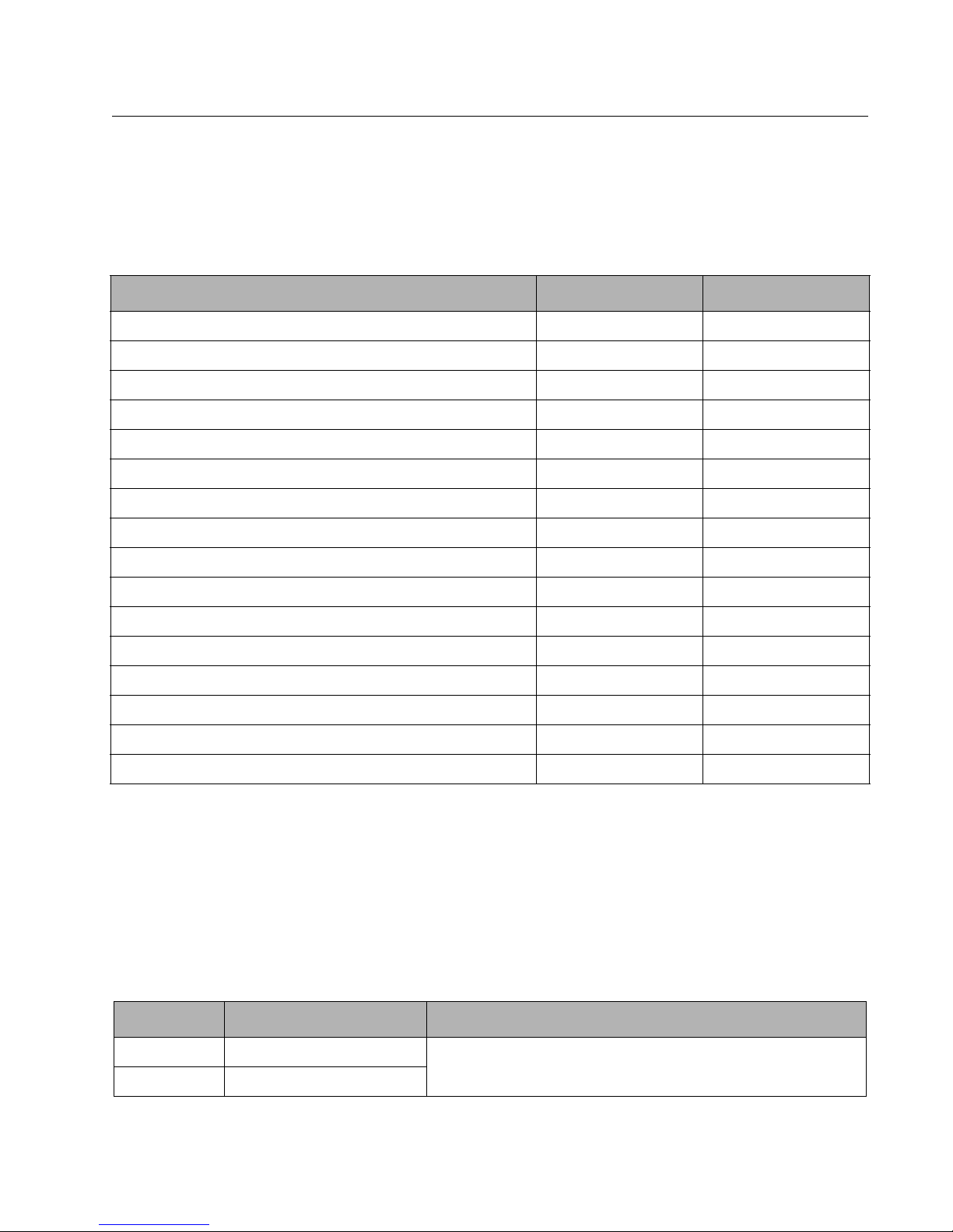
Chapter 4
Peripheral Interfaces
Details on peripheral interfaces on the Stylistic ST5000 Tablet PC and/or Tablet Dock are described in this chapter.
The Stylistic ST5000 Tablet PC and Tablet Dock provide the following peripheral interfaces:
Table 4-1. Peripheral interfaces
Interface Tablet PC Quantity Tablet Dock Quantity
DC Input connector 1 1
Wireless LAN port 1 --
IEEE 1394 jack 1 1
External Monitor port 1 1
Line Out jack -- 1
IrDA port 1 --
Infrared keyboard port 2 --
Universal Serial Bus (USB) 2.0 port 2 3
RJ-11 modem jack 1 --
RJ-45 LAN jack 1 1
Stereo headphone jack 1 --
Microphone jack 1 --
PC Card socket 1 --
Smart Card slot 1 --
SD/Memory Stick slot 1 --
System interface port* 1 1
* Note that the system interface port allows you to connect the optional Stylistic ST5000 Tablet Dock.
Pin assignments for peripheral interfaces on the Stylistic ST5000 Tablet PC are given in the following sections.
DC Power Input 4
The DC power input connector connects to the AC adapter or auto adapter to power the Tablet PC. The DC power
input connector is a two-conductor connector with a center pin and sleeve. Pin assignments for this connector are
given in Table 4-2.
Table 4-2. DC Power Input Connector Pin Assignments
Conductor Description Comments
Center Pin 16 Volts DC ±10%, 3.75 A (Hosiden part number HEC3900-01-010)
Sleeve Ground
When a DC power source is connected to the DC power input on the Tablet PC, circuitry built into the Tablet PC
provides protection against reverse polarity and overvoltage.
This connector is a EIAJ-RC5320A standard connector. S
DC Power Input 36
Page 41
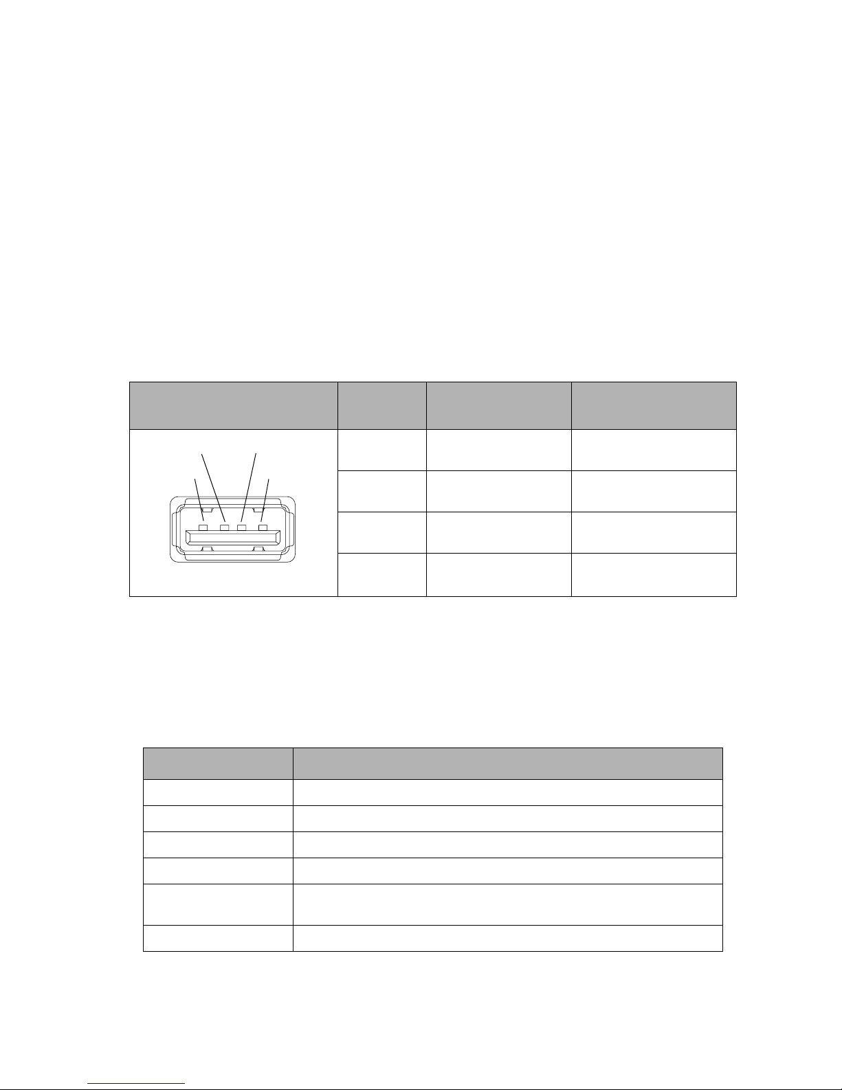
Universal Serial Bus Port 4
The Tablet PC and Tablet Dock provide Universal
Serial Bus (USB) ports that are compliant with the
Universal Serial Bus Specification Revision 2.0. A USB
port is a powered USB hub and can support
concurrent operation of up to 127 devices.
The Stylistic ST5000 Tablet PC provides two USB
ports, and functions as a USB host. The system
supports high-power, bus-powered functions as
defined in the USB specification. System resources for
the USB are assigned by the operating system, no
software configuration is necessary; however, it may
be necessary to install drivers and application
software to support your USB device. The Stylistic
ST5000 Tablet Dock provides three USB ports.
Table 4-3. USB Port Contacts
Contact Pin Locations
Position 3
Position 4
Position 2
Position 1
Contact
Number
1 5V Cable power (+ 5 volts DC,
2 DATA - Data
Ensure that your USB configuration does not exceed
the individual port maximum load on the total
system load. Note that the conductor gauge and
length of your USB cabling will affect the voltage
drop and signal propagation between USB devices.
Refer to the Universal Serial Bus Specification for
details on cable requirements or contact your cable
vendor (see “Related Documentation” on page 2.)
Also note that some USB devices are self-powered
and do not draw power over the USB cable. Contact
pin assignments for the USB port are shown in the
table below.
Signal Name Signal Description
500mA)
3 DATA + Data
4 GND Cable ground
IrDA Port 4
The IrDA port on the Stylistic ST5000 Tablet PC is
compliant with the Infrared Data Association (IrDA)
Standard Revision 1.1. Specifications for the IrDA
port on the Tablet PC are given below. Before you can
Table 4-4. IrDA Port Specifications
Feature Specification
Standard supported IrDA Standard Revision 1.1
Distance Up to 1 meter point to point (environmental conditions affect usable range)
Conveyable wave Infrared rays (wavelength peak 875 nm)
Signal Send data / Receive data
Modulation/Data Rate IrDA SIR: 9.6 - 115.2 Kbps
IrDA FIR: 4,000.0 Kbps
use the IrDA port, the Serial Port B Device BIOS
option must be set to IrDA or FIR. See “IrDA Port
Configuration Submenu Options” on page 12 for
details on BIOS options for the IrDA port.
Angle 0° to 15° from center of beam (30° viewing angle)
Universal Serial Bus Port 37
Page 42
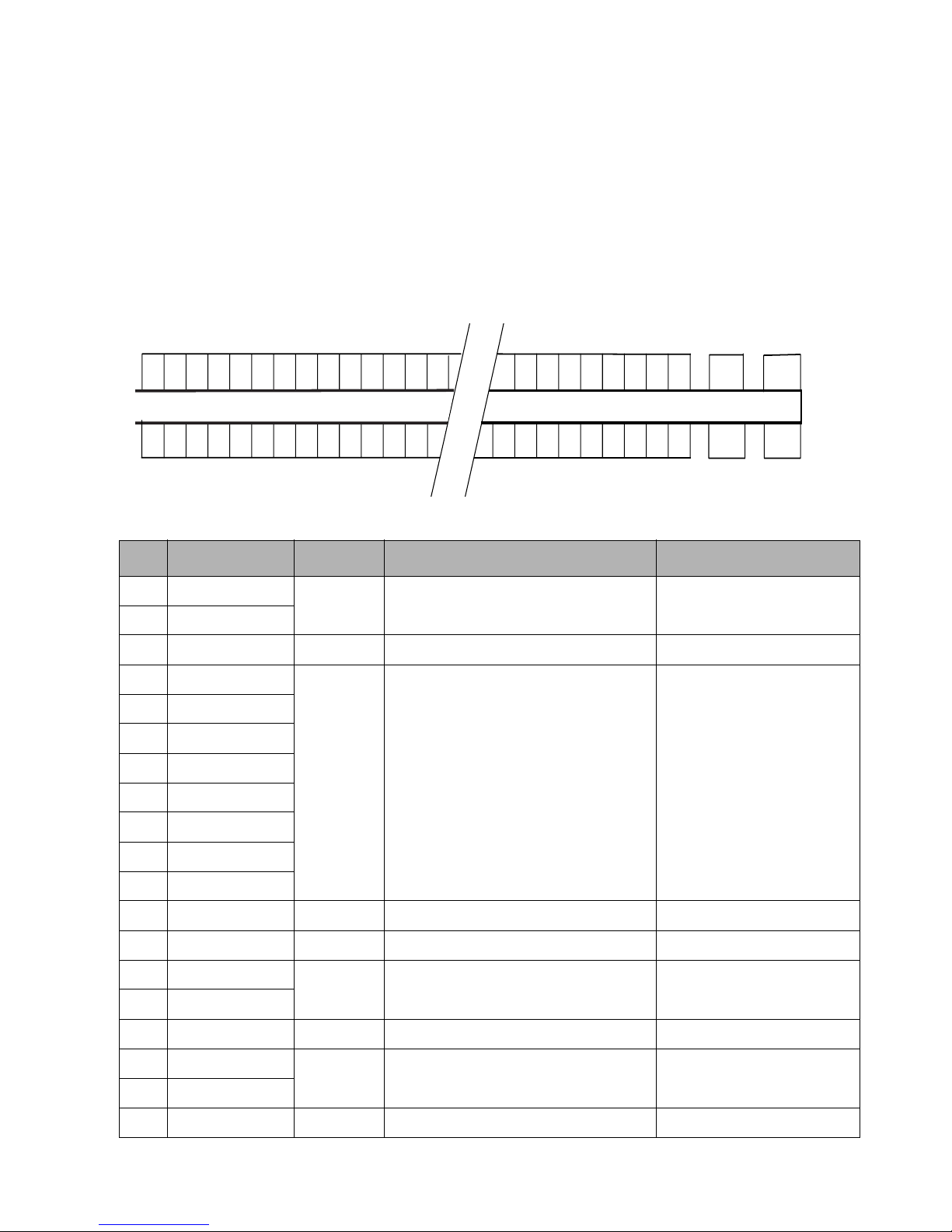
Tablet Dock Interface Port 4
The Tablet Dock interface port on the Stylistic
ST5000 Tablet PC allows you to attach the Stylistic
ST5000 Tablet Dock. The interface port is a 100-pin
connector. The following figure and table show the
pin locations for the interface port connector on the
Tablet PC. Signals designated with the “pound” (#)
symbol are active low.
• Signal names listed in the second column of this
table are not industry standard signal names.
They are provided to assist in cross-referencing
these signal names when they appear elsewhere.
• The connectors used for the system interface port
NOTES
are manufactured by Hirose. Connector part
numbers are: EX80-1005 (main unit) and
EX80-100P1 (tablet dock side)
100 99
50
98
97
49 48 47
5354
43
52
2
51
1
Table 4-5. Tablet Dock Interface Connector Pin Assignments
Pin Signal Name Level Description Port or Connector
1 GND1
2 GND1
3 SAFE +5V Dock Detect Docking Station
4 PWR_DOCK
5 PWR_DOCK
6 PWR_DOCK
7 PWR_DOCK
8 PWR_DOCK
9 PWR_DOCK
10 PWR_DOCK
11 PWR_DOCK
12 NC -- -- --
13 GND1 GND Ground
14 USB_P3NC
15 USB_P3PC
16 GND1 GND Ground
GND Ground
+5V PWR_DOCK
17 Reserve
18 Reserve
19 GND1 GND Ground
Tablet Dock Interface Port 38
Page 43

Table 4-5. Tablet Dock Interface Connector Pin Assignments
Pin Signal Name Level Description Port or Connector
20 Reserve
21 Reserve
22 GND1 GND Ground
23 DOCK_IDO
24 DOCK_IDO
25 TAB_SI
26 ROTATE_SMI
27 GND1 GND Ground
28 TRD3- Giga-LAN
29 TRD3+ Giga-LAN
30 NC
31 GND
32 NC
33 TRD2- Giga-LAN
34 TRD2+ Giga-LAN
35 GND1 GND Ground
36 GND_AUD GND Ground for Audio
37 LOUTL Line Out
38 GND_AUD GND Ground for Audio
39 LOUTR Line Out
40 GND_AUD GND Ground for Audio
41 GND1 GND Ground
42 TRD1-(RXD1-) Giga-LAN
43 TRD1+(RXD1+) Giga-LAN
44 NC
Reserve45 GND1
46 NC
47 TRD0-(TXD1-) Giga-LAN
48 TRD0+(TXD1+) Giga-LAN
49 GND1
50 DOCK_ON1
51 PWR_EXDCIN +16V DC-IN
52 PWR_EXDCIN
Tablet Dock Interface Port 39
Page 44

Table 4-5. Tablet Dock Interface Connector Pin Assignments
Pin Signal Name Level Description Port or Connector
53 DOCK_ON0
54 GND1
55 GND1
56 GND1
57 GND1
58 GND1
59 GND1
60 GND1
61 GND1
62 BAY_ID0
63 BAY_ID1
64 BAY_ID2
65 BAY_ID3
66 Reserve
67 Reserve
68 Reserve
69 GND1
70 GND1
71 TAB_SO
72 PWR_TAB10
GND Ground
GND Ground
73 TAB_SI
For debugging
74 TAB_SCK
75 PWR_TAB33
76 TAB_RST#
77 GND1 GND Ground
78 D_VGACLK
CRT
79 D_VGADATA
80 GND1 GND Ground
81 D_VGAVS
CRT
82 D_VGAHS
83 GND1 GND Ground
84 GND1 GND Ground for CRT
85 D_VGAB CRT
Tablet Dock Interface Port 40
Page 45

Table 4-5. Tablet Dock Interface Connector Pin Assignments
Pin Signal Name Level Description Port or Connector
86 GND1 GND Ground for CRT
87 D_VGAG CRT
88 GND1 GND Ground for CRT
89 D_VGAR CRT
90 GND1 GND Ground for CRT
91 GND1 GND Ground
92 GND1 GND Ground for IEEE 1394
93 D_TPB1- IEEE 1394
94 D_TPB1+ IEEE 1394
95 GND1 GND Ground for IEEE 1394
96 D_TPA1- IEEE 1394
97 D_TPA1+ IEEE 1394
98 GND1 GND Ground for IEEE 1394
99 GND1 GND Ground
100 SAFE
Tablet Dock Interface Port 41
Page 46
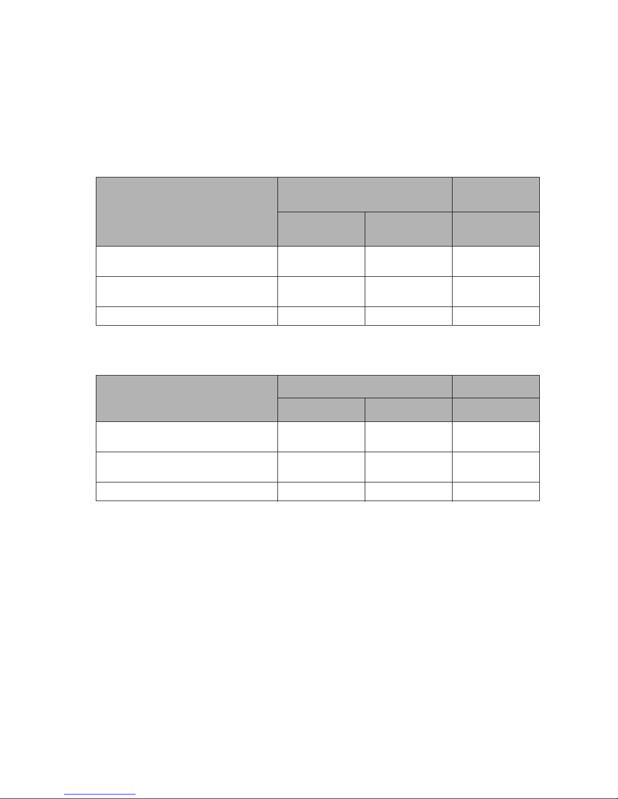
Audio Jacks 4
All audio jacks on the Stylistic ST5000 Tablet PC are
stereo mini jacks. Some audio functions on the Tablet
PC are disabled when audio jacks are used. Table 4-6
shows which audio inputs are disabled when inputs
on the Tablet PC and Tablet Dock are used (enabled).
when outputs on the Tablet PC and Tablet Dock are
used. Note that using one of the jacks on the system,
the other system device is disabled (e.g., when an
external microphone is used, the internal microphone
is disabled).
Table 4-7 shows which audio outputs are disabled
Table 4-6. Active Audio Inputs
Tablet PC
Input Activity
Microphone
(built-in)
Microphone On
(microphone built into Tablet PC)
Tablet PC Microphone jack used
(external microphone connected)
Tablet Dock Line In jack used NA NA Enabled
“NA” indicates that the condition does not apply. (The condition has no effect on the given input.)
Enabled Plug not inserted NA
Disabled Enabled NA
Microphone
Input Jack
Table 4-7. Active Audio Outputs
Tablet Dock
Line Input Jack
Tablet PC Tab l et Dock
Output Activity
Speaker (built-in) Headphone Jack Line Output Jack
Speaker On
(speaker built into Tablet PC)
Tablet PC Headphone jack used
(external headphone connected)
Tablet Dock Line Output jack used NA NA Enabled
“NA” indicates that the condition does not apply. (The condition has no effect on the given output.)
Enabled Plug not inserted NA
Disabled Enabled NA
Audio Jacks 42
Page 47
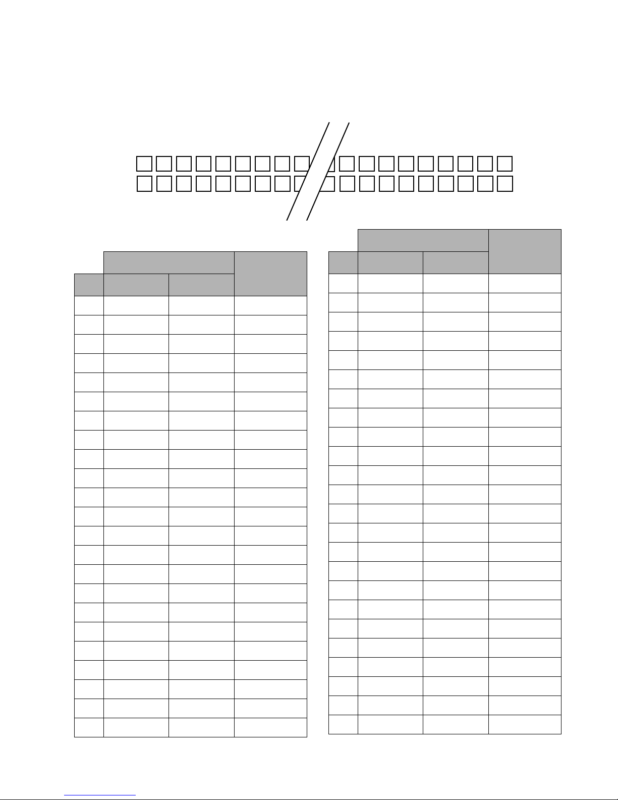
PC Card Port 4
The PC Card socket is compliant with PCMCIA Card
standard 3.0. The table and figure below show the pin
assignments and pin locations for the PC Card port.
1234
35 36 37 38 39
5
Table 4-8. PC Card Pin Assignments
16-bit PC Card Interface
CardBus
Pin Memory-Only I/O & Memory
1 GND GND GND
2D3D3CAD0
3D4D4CAD1
4D5D5CAD3
5D6D6CAD5
6D7D7CAD7
7 CE1# CE1# CCBE0#
8 A10 A10 CAD9
9 OE# OE# CAD11
10 A11 A11 CAD12
11 A9 A9 CAD14
12 A8 A8 CCBE1#
13 A13 A13 CPAR
14 A14 A14 CPERR#
15 WE# WE# CGNT#
16 READY IREQ# CINT#
17 VCC VCC VCC
18 VPP1 VPP1 VPP1
19 A16 A16 CCLK
20 A15 A15 CIRDY#
21 A12 A12 CCBE2#
22 A7 A7 CAD18
23 A6 A6 CAD20
30 31 32 33 34
64
16-bit PC Card Interface
Pin Memory-Only I/O & Memory
65
66 67 68
CardBus
24 A5 A5 CAD21
25 A4 A4 CAD22
26 A3 A3 CAD23
27 A2 A2 CAD24
28 A1 A1 CAD25
29 A0 A0 CAD26
30 D0 D0 CAD27
31 D1 D1 CAD29
32 D2 D2 RFU
33 WP IOIS16# CCLKRUN#
34 GND GND GND
35 GND GND GND
36 CD1# CD1# CCD1#
37 D11 D11 CAD2
38 D12 D12 CAD4
39 D13 D13 CAD6
40 D14 D14 RFU
41 D15 D15 CAD8
42 CE2# CE2# CAD10
43 VS1# VS1# CVS1
44 RUF IORD# CAD13
45 RFU IOWR# CAD15
46 A17 A17 CAD16
47 A18 A18 RFU
PC Card Port 43
Page 48

16-bit PC Card Interface
CardBus
Pin Memory-Only I/O & Memory
48 A19 A19 CBLOCK#
49 A20 A20 CSTOP#
50 A21 A21 CDEVSEL#
51 VCC VCC VCC
52 VPP2 VPP2 VPP2
53 A22 A22 CTRDY#
54 A23 A23 CFRAME#
55 A24 A24 CAD17
56 A25 A25 CAD19
57 VS2# VS2# CVS2
58 RESET RESET CRST#
59 WAIT# WAIT# CSERR#
60 RFU INPACK# CREQ#
61 REG# REG# CCBE3#
62 BVD2 SPKR# CAUDIO
63 BVD1 STSCHG# CSTSCHG
64 D8 D8 CAD28
65 D9 D9 CAD30
66 D10 D10 CAD31
67 CD2# CD2# CCD2#
68 GND GND GND
PC Card Port 44
Page 49
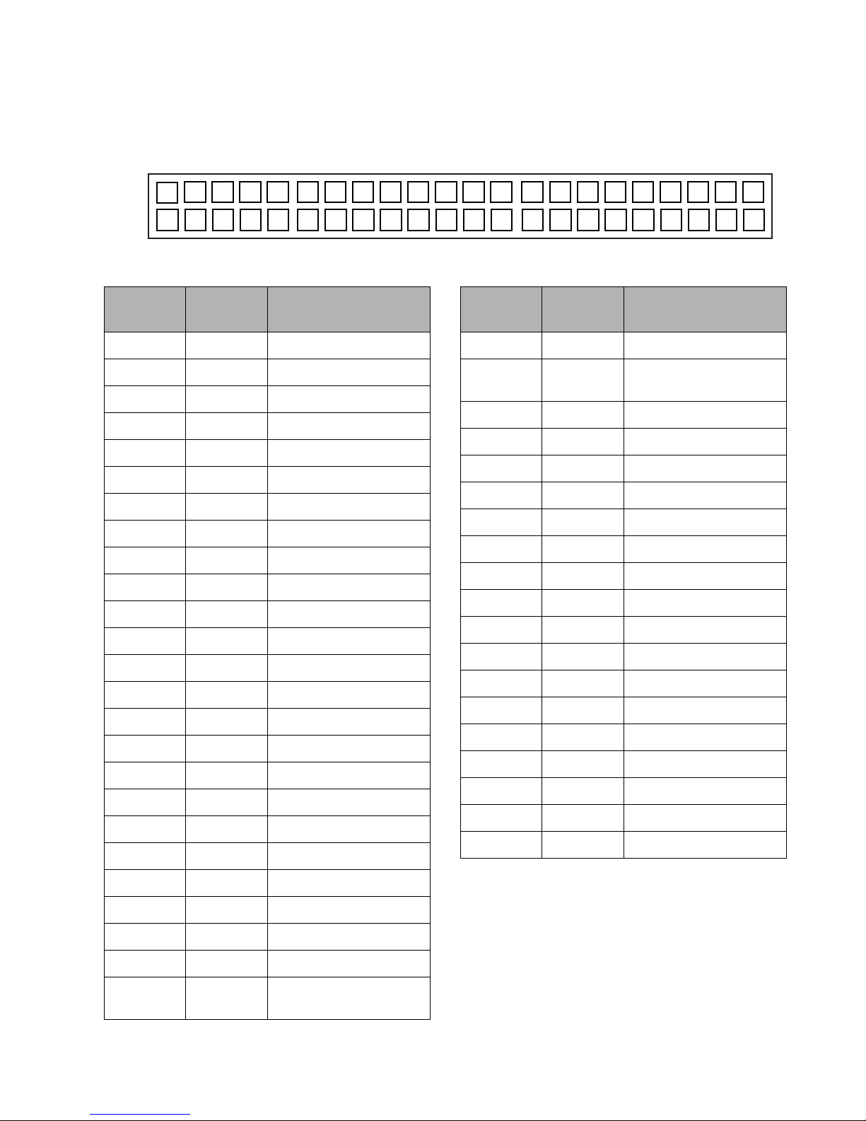
Hard Drive Port 4
Under ordinary circumstances, it is not necessary to
access the hard drive port. The pin locations are listed
43 41 39 37 35 33 31 29 27 25 23 21 19 17 15 13 11 9 7 5 3 1
30
32343638404244
Table 4-9. Hard Drive Pin Assignments
HDD side
Pin Number
1 1 RESET#
2 2 GND
33DATA7
44DATA8
55DATA6
66DATA9
77DATA5
88DATA10
99DATA4
10 10 DATA11
11 11 DATA3
12 12 DATA12
13 13 DATA2
14 14 DATA13
15 15 DATA1
16 16 DATA14
17 17 DATA0
18 18 DATA15
19 GND
20 KEY
PCB side
Pin Number
Signal Name
and illustrated below in the event of hard
replacement.
1416
182022242628
12
Table 4-9. Hard Drive Pin Assignments
HDD side
Pin Number
26 24 GND
27 25 IORDY / #DDMARDY /
28 26 CSEL#
29 27 DMACK#
30 GND
31 28 INTRQ
32 29 IOCS16#
33 30 DA1
34 31 PDIAG#
35 32 DA0
36 33 DA2
37 34 CS0#
38 35 CS1#
39 36 DASP#
40 37 GND
41 38 +5V (LOGIC)
42 39 +5 V (MOTOR)
43 40 GND
44 RESERVE
PCB side
Pin Number
Signal Name
DSTROBE
246810
21 19 DMARQ
22 20 GND
23 21 DIOW# / STOP
24 22 GND
25 23 DIOR# / HDMARDY# /
HSTROBE
Hard Drive Port 45
Page 50
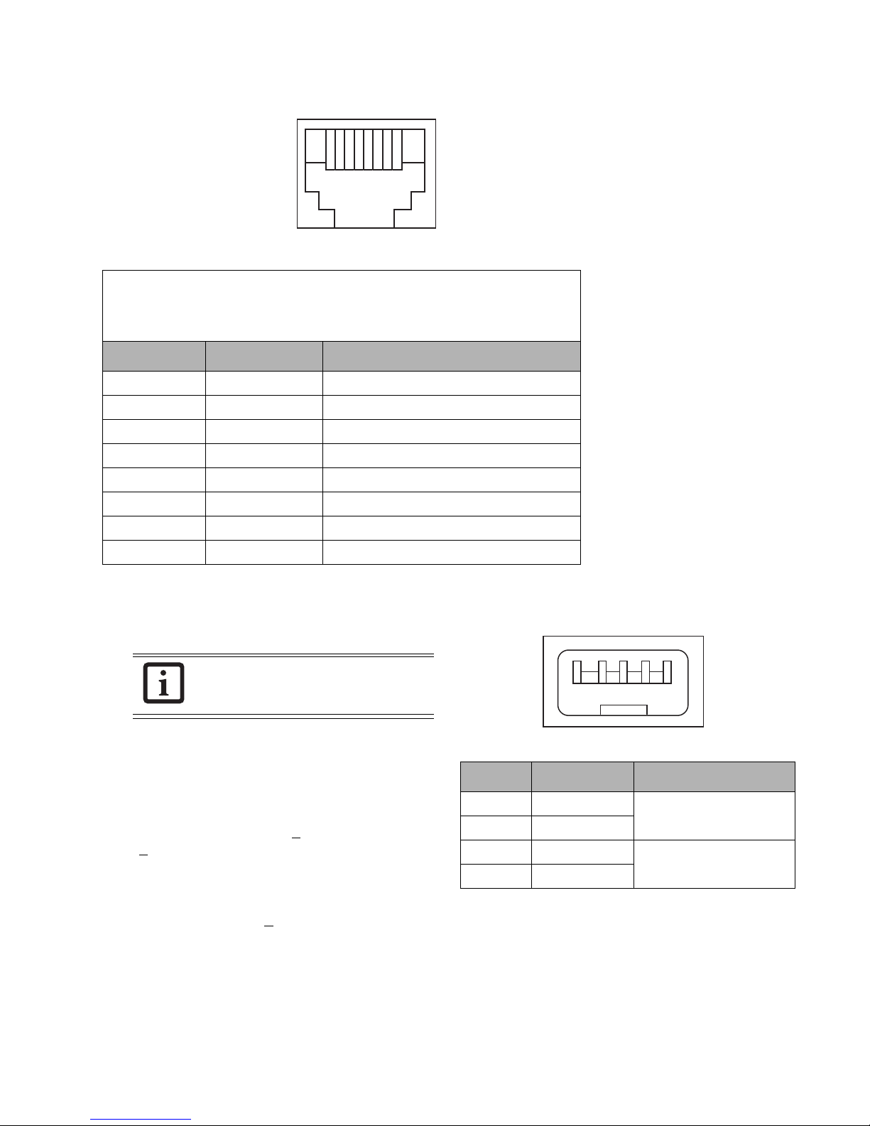
RJ-45 LAN Port 4
12345678
Table 4-10. LAN Port Pin Assignments
Note: The following table is correct for 10Base-T and 100Base-Tx, but not for
1000Base-T. For 1000Base-T pin assignments, go to one of the following Web sites:
http://www.foundrynet.com/services/documentation/EI48G/b_48Gcables.html
http://home.cfl.rr.com/bjp/RJ45pins.htm
Pin Signal Remarks
1 TX+ Transmit +
2 TX- Transmit -
3 RX+ Receive +
4 NC Not used
5 NC Not used
6 RX- Receive -
7 NC Not used
8 NC Not used
IEEE 1394 Port 4
The IEEE 1394 ports on the Tablet PC and the Tablet
Dock conform to IEEE 1394 standards.
The IEEE 1394 and USB ports on the Tablet
Dock are independent ports (i.e., they are not
pass-through ports).
IEEE 1394 cable characteristics follow:
• Suggested maximum cable length: 4.5 meters
• 110 ohms characteristic impedance - differential
mode
• 33 ohms characteristic impedance - common mode
• Relative propagation skew <
<
100ps @ 400 MHz (the difference between the
400ps @ 100 MHz and
differential mode propagation delay of the two
twisted pair conductors that must be measured in
the frequency domain).
• TPA to TPB crosstalk <
-26dB (within 1 MHz to
500 MHz range)
• Signal velocity equal to or less than 5.05ns/meter
• Signal pair attenuation:
100MHz = <2.3dB
200MHz = <3.2dB
400MHz = <5.8dB
1234
Table 4-11. IEEE 1394 Connector Pin Assignments
Pin Signal Remarks
1 TPB- Twisted Pair B - differential
2 TPB+
3 TPA- Twisted Pair A - differential
4TPA+
signal
signal
RJ-45 LAN Port 46
Page 51
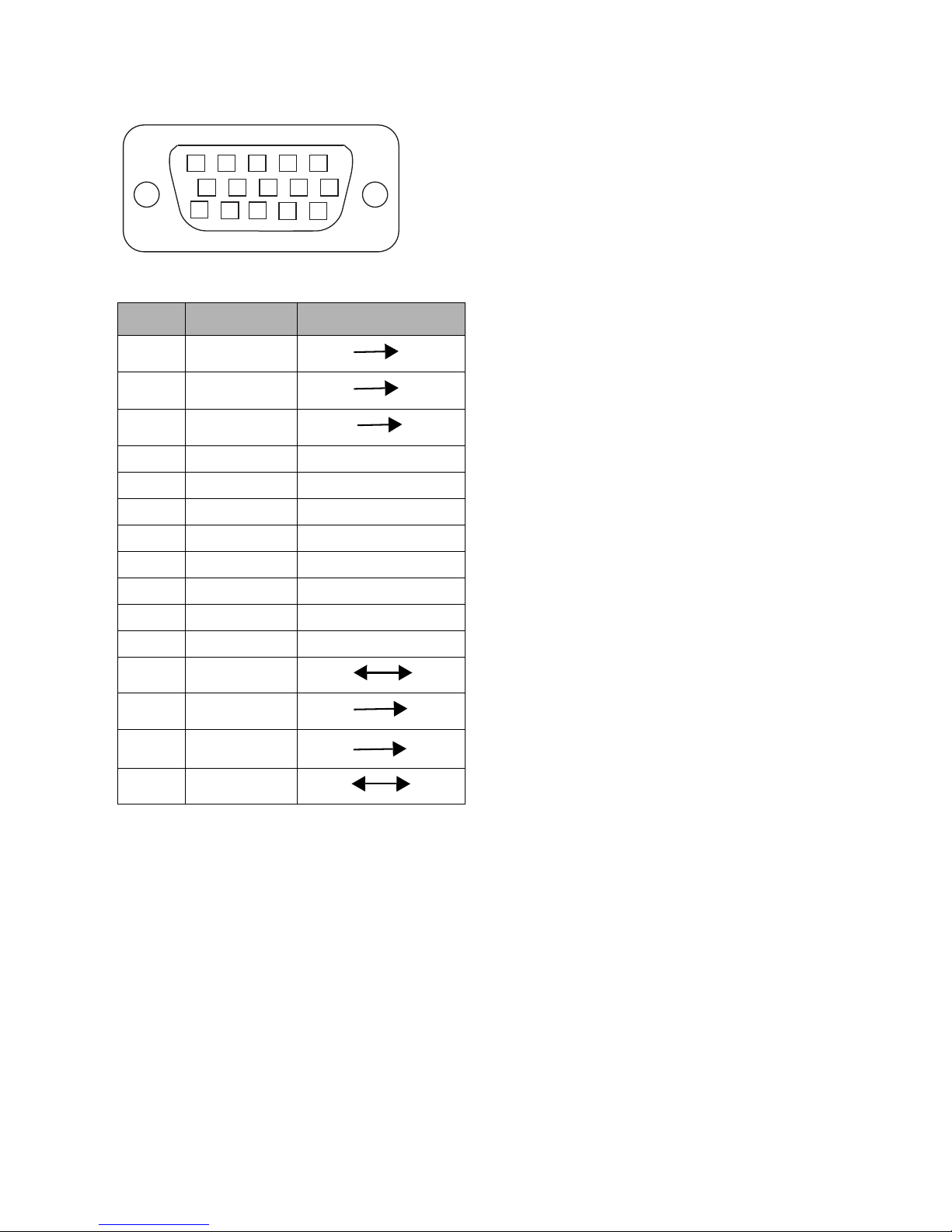
External Monitor Port
54 321
678910
11121315 14
Table 4-12. External Monitor Port Pin Assignments
Pin Signal (KB) Host I/O
1RED
2 GREEN
3BLUE
4NC --
5 GND --
6 GND --
7 GND --
8 GND --
9 DDCVCC --
10 GND --
11 NC --
12 DDCDATA
13 HSYNC
14 VSYNC
15 DDCCLK
IEEE 1394 Port 47
Page 52

Chapter 5
System Power
This chapter covers the Stylistic ST5000 Tablet PC’s system power hardware, power management states, and state
transitions.
System Power Hardware 5
The Stylistic ST5000 Tablet PC uses components designed for low power consumption in mobile applications. DC
power, whether supplied by the battery pack or an external source, is regulated to different voltage levels required to
power various components in the system.
Battery Pack 5
When the system is not connected to external power, system power is provided by the battery pack. When an
external DC power source is connected to the Tablet PC, the battery pack is gradually charged and the system is
powered by the external source.
The battery pack can also be removed from the Tablet PC and charged in an external charger. A bridge battery built
into the Tablet PC powers the system in suspend mode for approximately 5 minutes while the battery pack is
removed.
Note: Do not remove the battery pack while the system is running unless an AC Adapter is connected. Suspend
system operation or shut down the system before removing the battery pack. The bridge battery will not power
the system in the Fully On state.
The Tablet PC is equipped with a microcontroller, called the power management microcontroller unit (PMU),
which is dedicated to managing battery pack power. The battery pack charge is monitored by the PMU. The PMU
determines the percent of charge remaining in the battery pack, controls the battery level, and supplies battery status
information to the system through a dedicated interface.
A low voltage level detect circuit (independent of the PMU) measures the battery pack voltage level to determine
whether the battery pack voltage has dropped to the critically low level (the critically low voltage varies depending on
total current draw). When the system is running and the critically low voltage level is reached, the circuit forces the
system into Suspend mode and the battery level window indicates the critically low condition.
When the system is forced into Suspend mode by a critically low battery, the system is powered by the remaining
charge in the battery pack or the bridge battery (whichever has the highest voltage). In this mode, the Suspend/
Resume button is disabled and system operation cannot be resumed until either an external DC power source is
connected or a battery pack with adequate charge is installed.
48
Page 53
DC Power Inputs 5
External DC power can be connected at two locations on the Tablet PC:
• DC power connector on the Tablet PC
• System interface connector (via Tablet Dock)
A DC power source connected to any of these inputs must provide 3.75 amps at a continuous DC voltage of 16 volts
±10%. Specifications for the DC input connectors on the Tablet PC and Tablet Dock are given below.
Table 5-1. DC Input Connectors
Connector type EIAJ RC-5320A Type 5
Connector vendor Hosiden
Vendor part number* HEC3900-01-010
Pin assignments Center conductor: +16 VDC ±10%
Sleeve: ground
* This is the part number for the female DC input connector on the Tablet PC and the Tablet Dock.
System Power Hardware 49
Page 54
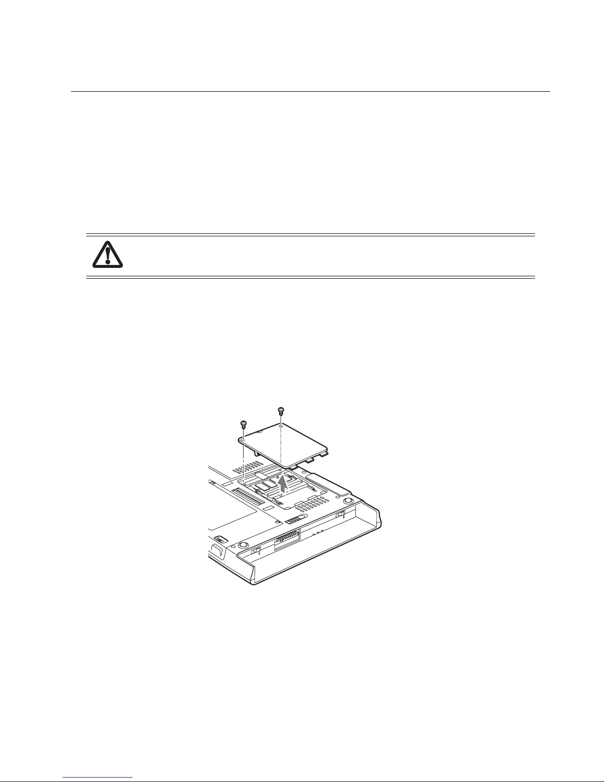
Chapter 6
Installing Hardware Options
This chapter provides procedures for installing DIMM cards, the WLAN device, and the internal IDE hard drive.
Installing/Removing a DIMM Module 6
There are two DIMM slots in your Tablet PC. 256 MB, 512 MB, and 1 GB modules are available, so you can install a
combination of up to 2 GB in the system.
DIMM replacement should only be performed at a static-free workstation. Avoid touching connector pins, circuit
boards, or other circuit components on the drive or Tablet PC. Electrostatic discharge caused by doing so can damage
sensitive components.
Installing a Memory Module 6
To install a DIMM module in the Tablet PC:
1. Ensure that the Tablet PC is off. To do so, carry out the Shut Down command in the Start menu. (Do not attempt to
remove or install a DIMM module when the system is in Suspend mode or running.)
2. Remove the battery pack and store in a safe place.
3. Remove the two screws from the cover plate on the back of the Tablet PC and remove the cover plate as shown in Figure
6-1.
Figure 6-1. Accessing the Memory Slot
4. Insert the DIMM module in the socket at an angle and push it down until it locks into place as shown in Figure 6-2.
Note that the DIMM module is keyed to prevent it from being inserted backwards.
50
Page 55
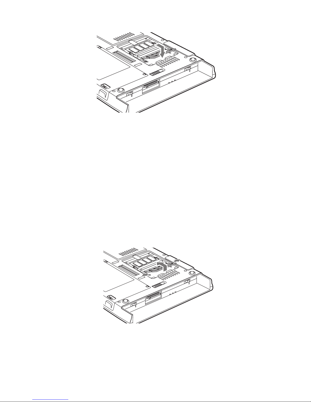
Figure 6-2. Installing a DIMM Module
5. Reinstall the cover and screws that you removed in step 2.
6. Reinstall the battery pack.
7. Confirm that the DIMM module is recognized by the system. To do so, run BIOS Setup. The size of the DIMM module
should be displayed in the Info menu in BIOS Setup.
The DIMM module is installed in the Tablet PC and you can now use the system.
Removing a Memory Module 6
To remove a DIMM module:
1. Ensure that the Tablet PC is off. To do so, carry out the Shut Down command in the Start menu. (Do not attempt to
remove or install a DIMM module when the system is in Suspend mode or running.)
2. Remove the battery pack and store in a safe place.
3. Remove the screws from the cover plate on the back of the Tablet PC and remove the cover plate as shown in Figure 6-1.
4. Spread the fingers on the socket that lock the DIMM module in place until the DIMM module is loose.
5. Remove the DIMM module from the socket.
6. Reinstall the battery pack.
The DIMM module is now removed from the Tablet PC. Refer to “Installing a Memory Module” on page 50 to install a
new DIMM module.
Figure 6-3. Removing a DIMM Module
Installing/Removing a DIMM Module 51
Page 56
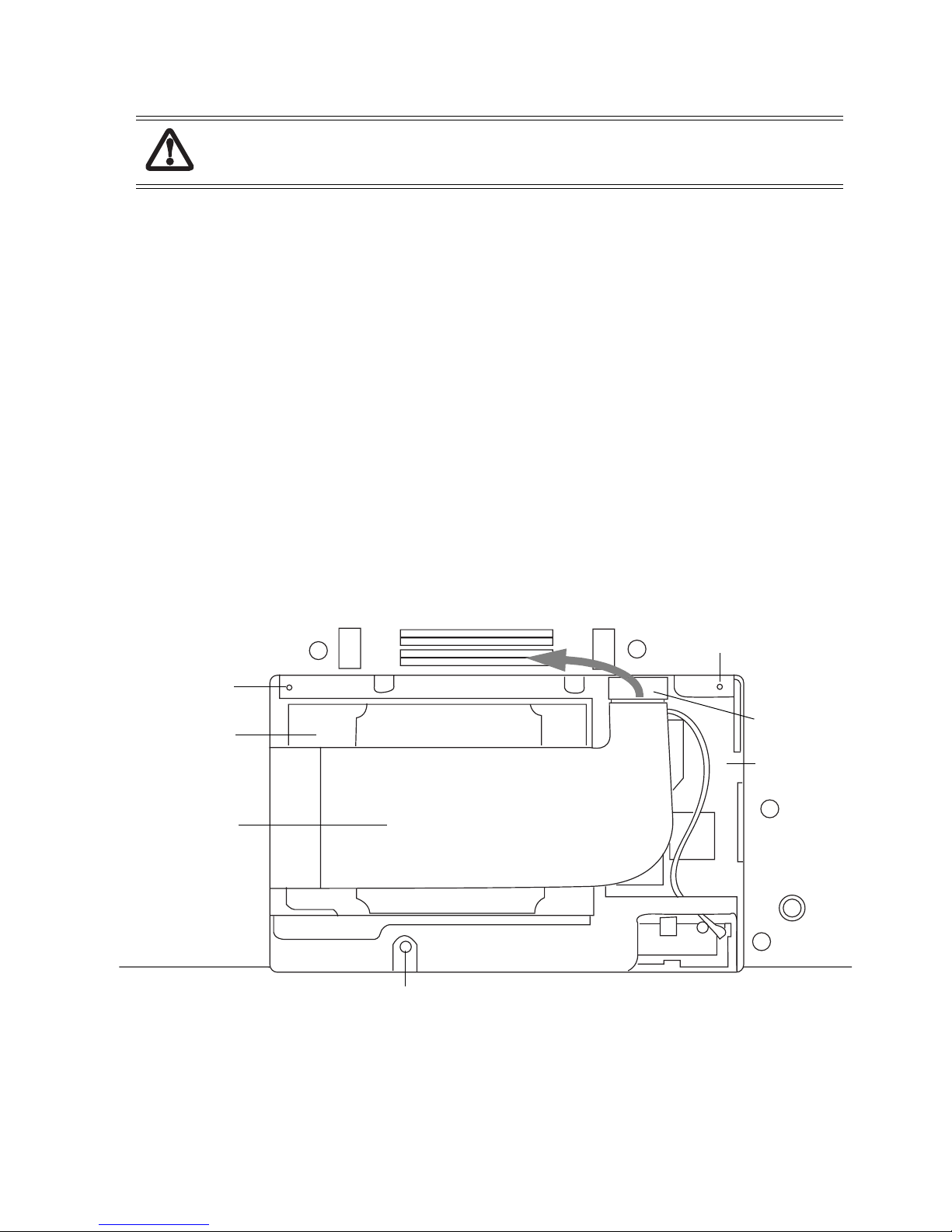
Replacing/Installing a Wireless LAN Module 6
Wireless LAN Module replacement should only be performed at a static-free workstation. Avoid
touching connector pins, circuit boards, or other circuit components on the module or Tablet PC.
Electrostatic discharge caused by doing so can damage sensitive components.
Removing a Wireless LAN Module 6
Note that the antenna module is installed only if the system was purchased with a Wireless LAN device installed.
1. Remove the three screws holding the Wireless LAN Module cover. Slide the cover away from the system to
disengage it from its slots. Set the cover aside for later reinstallation.
2. Unplug the hard drive connector (Figure 6-1) to reveal the Wireless LAN device.
3. Carefully disconnect the small connector from the Antenna Module (Figure 6-2). Be careful not to damage the
small jumper wire that connects the module with the Wireless LAN Module.
4. Carefully unplug the small cable connector (Figure 6-2) from the Wireless LAN Module.
5. Press the two card latches that hold the Wireless LAN Module away from the module (as illustrated in Figure 6-2)
to disengage the module from the latches. The back of the module will pop up when it is disengaged.
6. Once the module is disengaged, pull it carefully from the card connector (11).
Installing a Wireless LAN Module 6
To install a new Wireless LAN Module, follow the instructions in “Removing a Wireless LAN Module” on page 52, in
reverse order.
Screw location
Screw location
Hard Drive
Hard Drive Cable
Screw location
Hard Drive
Connector
WLAN Card
Figure 6-1 Wireless LAN / Hard Drive Compartment
Replacing/Installing a Wireless LAN Module 52
Page 57
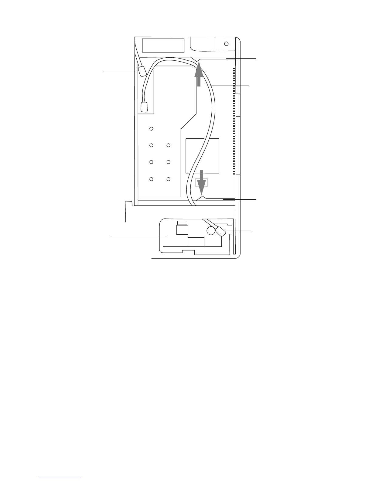
Cable
Connector
Antenna
Module
Latch
Jumper
Wire
Latch
Antenna Module
Connector
Figure 6-2 Removing the WLAN Device
Replacing/Installing a Wireless LAN Module 53
Page 58
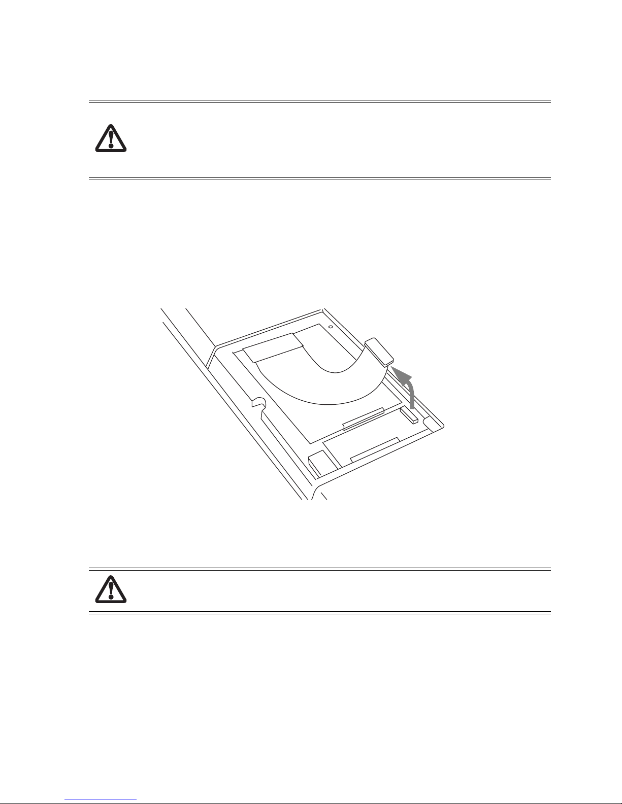
Replacing the IDE Hard Drive 6
The internal IDE hard drive in the Stylistic ST5000 Tablet PC can be removed and replaced, if necessary.
• Do not attempt to disassemble or modify the hard drive.
• Do not remove any labels from the hard drive.
• Hard drive replacement should only be performed at a static-free workstation. Avoid touching
connector pins and circuit boards on the drive or Tablet PC. Electrostatic discharge caused by doing
so can damage sensitive components.
Removing the Hard Drive 6
To remove the hard drive from the Tablet PC,
1. Close all applications and shut down the system completely.
2. Using a Phillips screw driver, remove the three screws in the WLAN/hard drive cover plate (see Figure 6-1. for
location). Slide the cover plate slightly towards the edge of the system to disengage it. Remove the cover.
3. Carefully disconnect the small connector by pulling upwards (reference Figure 6-3). Use care when disconnecting
this connector; it is attached to a delicate flex cable.
Do not pull the tab on the flex cable connector when lifting the drive. Doing so could damage the flex
cable; it is fragile.
4. Using your thumbs, push up the two corners of the hard drive (at the locations indicated in Figure 6-4). Lift the
drive out of the system.
Figure 6-3 IDE Hard Drive Cover Plate
Replacing the IDE Hard Drive 54
Page 59
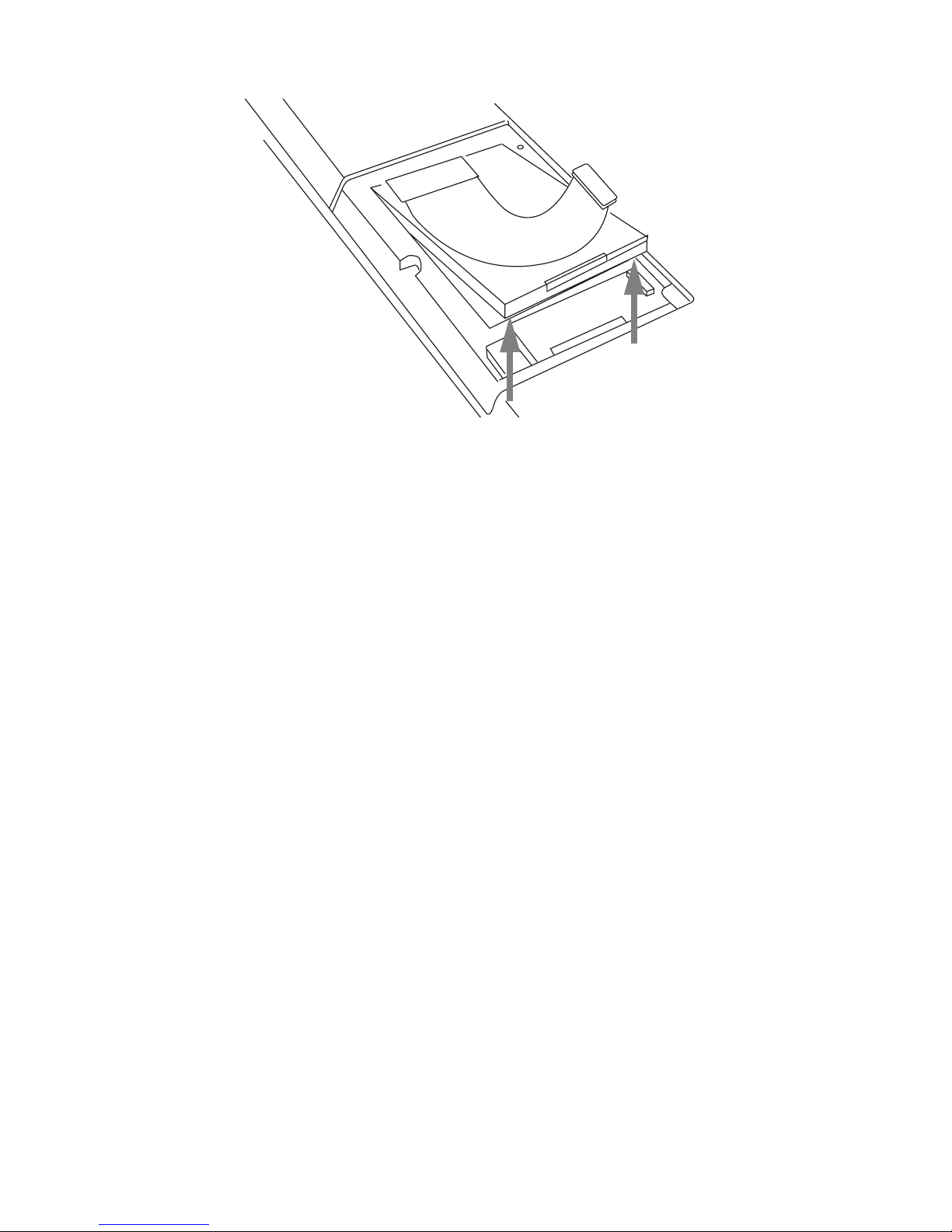
Figure 6-4 Removing the Hard Drive
5. Once the hard drive has been removed from the Tablet PC, you can install a new hard drive. If you are returning
the hard drive for repair, ensure that the packaging material will protect the drive sufficiently during shipment.
Installing the Hard Drive 6
To install the hard drive, follow the steps contained in the section entitled “Removing the Hard Drive” in reverse
order. Use care when installing the drive to prevent damage to the flex cable.
The hard drive is now installed in the Tablet PC.
Replacing the IDE Hard Drive 55
Page 60

Appendix A
AT Command Set
This Appendix contains a summary of AT commands used by the Stylistic ST5000 Tablet PC’s modem.
There are several things to note about this set of commands:
• Commands should be entered as ASCII characters.
• Commands should begin with “AT”, with a description of the character after the “AT”.
• The commands are not case-sensitive; upper and lower case characters are treated the same.
• All commands should be followed by the “CR” character stored in “S3”.
• Spaces are counted as characters.
• Command indication can be a selected letter or number message, or it can be no return message by designation.
• Data format is as follows:
Start bit Data bit Parity Stop bit
1 7 even 1
17odd1
1 7 none 2
1 8 none 1
Note: Baud rate and data format are detected by the “AT” character.
56
Page 61

AT Commands Table 6
AT Data Commands 6
The shaded portion of the table are stored with the AT&W command.
Command Specification Default
A/ Repeat last command.
A Answer command.
D Dial
T 123456789*0#ABCD
P 1234567890
W Wait for dial tone. Modem waits for a second dial tone before processing the
dial string.
@ Wait for quiet answer.
‘ Pause for a time specified by S8 before dialing.
! Hook flash
; Return to command mode after processing command.
S=n Dial a telephone number previously stored using the &Zn=x command. The
range of n is 0-3.
E 0 Disables echo to the computer
1 Enables echo to the computer
H 0 Modem goes on-hook
1 Modem goes off-hook
I 0 Returns modem identity string and driver version number, same as I3
1 Calculates ROM checksum and displays it on the DTE.
3
3
3
2 Performs a ROM check and calculates and verifies the checksum, displaying OK
or ERROR.
3 Returns modem identity string and driver version number, same as I0
L 0 Selects low volume.
1 Selects low volume.
2 Selects medium volume.
3 Selects high volume.
M 0 The speaker is off.
1 The speaker is on until the modem detects the carrier signal.
2 The speaker is always on when modem is off-hook.
3 The speaker is on until the carrier is detected, except while dialing.
3
3
AT Commands Table 57
Page 62
Command Specification Default
N 0 When originating or answering, this is for handshake only at the
communication standard specified by S7 and the ATB command.
1 When originating or answering, begin the handshake only at the
communication standard specified by S7 and the ATB command. During
handshake, fallback to a lower speed may occur.
O 0 Instructs the modem to exit online command mode and return to data mode
(see AT Escape Sequence, +++).
P Select Pulse Dialing.
Q 0 Enables modem to send result codes to the computer.
1 Disables modem from sending result codes to the computer.
T Select Tone Dialing.
V 0 Displays results codes as digits.
1 Displays results codes as text.
X Result Code Selection and Call Progress Monitoring
Dialing Result Code No Dialtone Busy Code
0 After S6
1 After S6
2 Wait Dial Tone
(S6)
Displays
“CONNECT”
Displays
“CONNECTXXX”
Displays
“CONNECTXXX”
Not displays Not displays
Not displays Not displays
Displays Not displays
3
3
3
3 After S6
4 Wait Dial Tone
(S6)
Z Reset and recall stored user profile.
&C 0 State of the carrier from remote modem is ignored. DCD circuit is always on.
1 DCD turns on when the remote modem’s carrier signal is detected, and off
when the carrier signal is not detected.
&D 0 Ignores status of DTR signal.
1 Enters command state upon On-to-Off transition of DTR.
2 Goes on hook upon On-to-Off transition of DTR.
3 Goes on hook and resets upon On-to-Off transition of DTR.
&F Recall factory setting as active configuration.
&K 0 Disable flow control.
3 Enable RTS/CTS (hardware) flow control.
4 Enable XON/XOFF flow control.
Displays
“CONNECTXXX”
Displays
“CONNECTXXX”
Not displays Displays
Displays Displays
3
3
3
3
AT Commands Table 58
Page 63
Command Specification Default
&P 0 39% make/break ratio. 10PPS
1 33% make/break ratio. 10PPS
2 33% make/break ratio. 20PPS
&S 0 DSR always ON.
1 DSR comes on when establishing a connection and goes off when the
connection ends.
&T 0 Abort. Stops any test in progress.
1 Local analog loop.
&V View active configuration and stored profile.
&W Store current configuration
&Zn Store telephone number. (n=0, 1, 2, 3)
/A 0 Sets MNP block size max. 64 characters
1 Sets MNP block size max. 128 characters
2 Sets MNP block size max. 192 characters
3 Sets MNP block size max. 256 characters
/Bn Transmit break to remote. /B1-/B9 break length in 100ms units. 3
/K 1) Receives break from the DTE when on-line mode. 5
3
3
3
0, 2, 4 Enter on-line command mode, no break set to remote.
1 Clear data buffers and send break to remote modem
3 Send break to remote modem immediately.
5 Send break to remote modem in sequence with transmitted data.
2) On-line command mode during a data connection. The /B is received in order to send
a break to the remote.
0, 1 Clear data buffers and send break to remote modem.
2, 3 Send break to remote modem immediately.
4, 5 Send break to remote modem in sequence with data.
3) Break is received from a remote modem during on-line mode.
0, 1 Clears data buffers and sends break to the DTE.
2, 3 Send a break immediately to the DTE.
4, 5 Send a break in sequence with received data to the DTE.
AT Commands Table 59
Page 64

Command Specification Default
/N 0 Normal speed-buffered mode.
1 Direct mode (if parallel I/F is selected, same as /NO).
2 MNP reliable mode (MNP -> disconnect)
3 Auto-reliable mode (LAPM -> MNP -> NORMAL -> disconnect).
Same as /N5.
4 LAPM-reliable mode (LAPM -> disconnect)
5 Auto-reliable mode (LAPM -> MNP -> NORMAL -> disconnect).
Same as /N3.
/V 0 Disable protocol result code appended to DCE speed.
1 Enable protocol result code appended to DCE speed.
2 Same as /V1.
/X 0 Do not pass XON/XOFF flow control characters.
1 Pass XON/XOFF flow control characters.
-V90=<n> =0 Disable V.90
=1 Enable V.90 Auto Rate
=2 Attempt to connect at 28000 bit/s
=3 Attempt to connect at 29333 bit/s
=4 Attempt to connect at 30666 bit/s
=5 Attempt to connect at 32000 bit/s
3
3
3
3
=6 Attempt to connect at 33333 bit/s
=7 Attempt to connect at 34666 bit/s
=8 Attempt to connect at 36000 bit/s
=9 Attempt to connect at 37333 bit/s
=10 Attempt to connect at 38666 bit/s
=11 Attempt to connect at 40000 bit/s
=12 Attempt to connect at 41333 bit/s
=13 Attempt to connect at 42666 bit/s
=14 Attempt to connect at 44000 bit/s
=15 Attempt to connect at 45333 bit/s
=16 Attempt to connect at 46666 bit/s
=17 Attempt to connect at 48000 bit/s
=18 Attempt to connect at 49333 bit/s
=19 Attempt to connect at 50666 bit/s
=20 Attempt to connect at 52000 bit/s
AT Commands Table 60
Page 65
Command Specification Default
=21 Attempt to connect at 53333bit/s
=? Shows the current value.
? Shows the range [0-21]
%C 0 V.42bis/MNP5 disable. No data compression.
1 V.42bis/MNP5 enable. Data compression enabled.
%E 0 Disable line quality monitor and auto-retrain.
1 Enable line quality monitor and auto-retrain.
2 Enable line quality monitor and fall back/fall forward.
3
3
AT Commands Table 61
Page 66
AT Fax (Class1) Commands 6
Command Specification Default
+FCLASS ? Service class indication (*1)
=n Service class selection (*2)
=? Service class capabilities (*2)
+FTS =n Transmission silence (n=0-255, 10ms intervals)
+FRS =n Receive silence. (n=0-255, 10ms intervals)
+FTM =n Transmit FAX data with <n> carrier.
=? Transmit FAX modulation. (*3)
+FRM =n Receive FAX with <n> carrier.
=? Receive FAX modulation. (*3)
+FTH =n Transmit HDLC data with <n> carrier.
=? Transmit HDLC data modulation (*3).
+FRH =n Receive HDLC data with <n> carrier.
=? Receive HDLC data modulation. (*3).
*1: 000 -> Data mode *2:0 ->Data mode
001 -> Facsimile Class 1 1 -> Facsimile Class 1
008 -> Voice Mode 8 -> Voice Mode
3
080 -> VoiceView Mode (not supported) 80 -> VoiceView Mode (not supported)
*3: Modulation by parameter
3: V.21 Channel2 300bps
24: V.27ter 2400bps
48: V.27ter 4800bps
72: V.29 7200bps
73: V.17 7200bps (long
74: V.17 7200bps (short)
96: V.29 9600bps
97: V.17 9600bps (long
98: V.17 9600bps (short)
121: V.17 12000bps (long)
122: V.17 12000bps (short)
145: V.17 14400bps (long)
146: V.17 14400bps (short)
AT Commands Table 62
Page 67
V.25ter AT Commands 6
Command Specification Description
+GMI Return ‘Lucent Data/Fax’ Manufacturer Identification
+GMR Return Lucent driver version number (e.g., 5.54) Version/Revision Information
+GMM Return ‘H.324 video-ready rev. 1.0’ Modem Identification
AT+A8E=<v80> v8o 1: The default value disables the CI origination
option while in V.8 negotiation. However, the
modem, when initiating the call as a data call,
detects ANSam and is capable of starting in
V.34 mo d e.
6: Enables DCE control of V.8 and CI option.
v8a 1: The default value disables the CI option while
in V.8 negotiation. However, the modem,
when answering a call, sends the ANSam and
is capable of starting in V.34 mode.
5: Enables DCE control of V.8 and CI option.
v8cf 21h:
AT+A8E? Report current values of
AT+A8E=? Report supported ranges of values
+A8I:<v8cf><CR> This indication is used by an
Call function for H.324 calls.
c1h:
Call function for DSVD calls.
Defined for two conditions: as a
parameter to configure V.8
originating and answering
operation while the DCE is
on-hook.It initiates an action if
the DCE is off-hook. If enabled,
V.8 negotiation does not preclude
simultaneous implementation of
other negotiation means like
V.8bis, V.18, or V.32bis.
subparameter.
<v8o>, <v8a>, <v8cf>
answering DCE if +A8E,
<v8a>!=0, to indicate detection of
a V.8 CI signal, and report the
recovered Call Function octet(s).
Value <v8cf> is a hexadecimal
code octet that can take values as
shown above in +A8E command.
+A8M=<hexadecimal
coded CM or JM octet
string>
+A8A:<type><CR> 1:0:Indicates V.8 ANSam signal flags.
Refer to V.8 document for coding. Directs the DCE to send a V.8 CM
or JM signal using the specified
hexadecimal coded string.
Indicates no ANSam signal detected.
AT Commands Table 63
Page 68
S Register Table 6
Default is North America. The shaded portions of the table are stored with AT&W command.
Reg Function Units Default Range
*
S0 Auto answer ring number Rings 000 000-255
*JP000-015
S1 Ring counter. Read only. Rings 000 000-255
S2 Escape character ASCII 043 000-128
*
S3 Carriage return character (CR) ASCII 013 000-127
*
*
S4 Line feed character (LF) ASCII 010 000-127
*
*
S5 Backspace character (BS) ASCII 008 000-032
*
*
S6 Wait time for dial tone. sec 002 002-065
*JP 004 *JP004-065
* S7 Wait time for dial tone. sec 050 001-255
*JP035-059
* S8 Pause for dial delay modifier “,”. sec 002 002-065
*
S10 Carrier loss Disconnect time. 100ms 020 001-255
*
S11 DTMF Dialing speed. 1ms 095 050-150
*JP70-150
S12 Escape prompt delay. 20ms 050 000-255
S14 General bit mapped options status. (Read only)
0: Enable short form result codes ATV0 Bit 3
1: Enable long form result codes. ATV1
0: 10PPS AT&P0,
&P1
1: 20PPS AT&P2
S21 General bit mapped options status (Read only)
0: DTR behavior. AT&D0 Bits 4, 3
1: DTR behavior. AT&D1
2: DTR behavior. AT&D2
3
3
3
Bit 6
3: DTR behavior. AT&D3
0: DCD behavior. Bit 5
1: DCD behavior.
S Register Table 64
Page 69
“*” : These S-registers are country-specific.
“**” : These return to default value by &W command
“*JP” : Default for Japan mode
S22 Results bit mapped options status (Read only)
0: Displays “CONNECT” ATX0 Bits 6-4
4: Displays “CONNECT xxx” ATX1
5: ATX1 mode + dial tone detection ATX2
6: ATX1 mode + busy tone detection ATX3
7: ATX1 mode + dial & busy tone detection ATX4
0: 33% Make/Break ratio AT&P1,
1: 39% Make/Break ratio AT&P0
S24 Timer to control sleep mode.
000 = disable
S37 Dial line rate.
=0 Maximum modem speed
=1 Reserved
=2 1200 bits/s and 75 bits/s
=3 300 bits/s
=4 Reserved
=5 1200 bits/s
=6 2400 bits/s
=7 4800 bits/s
=8 7200 bits/s
&P2
3
3
sec 010 000,
Bit 7
005-065
3
=9 9600 bits/s
=10 12000 bits/s
=11 14400 bits/s
=12 16800 bits/s
=13 19200 bits/s
=14 21600 bits/s
=15 24000 bits/s
=16 26400 bits/s
=17 28800 bits/s
=18 31200 bits/s
=19 33600 bits/s
S Register Table 65
Page 70

S38 56K Dial Line Rate
=0 56K disabled
=1 56K enabled - automatic speed selection - maximum
modem speed.
=2 32000 bits/s
=3 34000 bits/s
=4 36000 bits/s
=5 38000 bits/s
=6 40000 bits/s
=7 42000 bits/s
=8 44000 bits/s
=9 46000 bits/s
=10 48000 bits/s
=11 50000 bits/s
=12 52000 bits/s
=13 54000 bits/s
=14 56000 bits/s
3
S91 Line Transmit Level.
This register is effective only for Japan.
-dBm 14 9-15
S Register Table 66
Page 71

Result Codes Summary 6
Result Code Numeric Description
OK 0 Command executed.
CONNECT 1 Modem connected to line.
RING 2 A ring signal has been detected.
NO CARRIER 3 Modem lost carrier signal, or does not detect carrier signal,
or does not detect answer tone.
ERROR 4 Invalid command.
NO DIALTONE 6 No dial tone detected.
BUSY 7 Busy signal detected.
NO ANSWER 8 No quiet answer.
CONNECT 2400 EC* 10 Connection at 2400 bits/s.
CONNECT 4800 EC* 11 Connection at 4800 bits/s.
CONNECT 9600 EC* 12 Connection at 9600 bits/s.
CONNECT 14400 EC* 13 Connection at 14400 bits/s.
CONNECT 19200 EC* 14 Connection at 19200 bits/s.
CONNECT 7200 EC* 24 Connection at 7200 bits/s.
CONNECT 12000 EC* 25 Connection at 12000 bits/s.
CONNECT 16800 EC* 86 Connection at 16800 bits/s.
CONNECT 300 EC* 40 Connection at 300 bits/s.
CONNECT 21600 EC* 55 Connection at 21600 bits/s.
CONNECT 24000 EC* 56 Connection at 24000 bits/s.
CONNECT 26400 EC* 57 Connection at 26400 bits/s.
CONNECT 28800 EC* 58 Connection at 28800 bits/s.
CONNECT 31200 EC* 59 Connection at 31200 bits/s.
CONNECT 33600 EC* 60 Connection at 33600 bits/s.
CONNECT 38400 EC* 28 Connection at 38400 bits/s. (DTE rate)
CONNECT 57600 EC* 18 Connection at 57600 bits/s. (DTE rate)
CONNECT 115200 EC* 87 Connection at 115200 bits/s. (DTE rate)
DELAYED 88 Delay is in effect for the dialed number.
BLACKLISTED 89 Dialed number is blacklisted.
BLACKLIST FULL 90 Blacklist is full.
CONNECT 32000 EC* 70 Connection at 32000 bits/s. (K56flex or V.90 mode)
CONNECT 34000 EC* 71 Connection at 34000 bits/s. (K56flex mode)
CONNECT 03600 EC* 72 Connection at 36000 bits/s. (K56flex or V.90 mode)
Result Codes Summary 67
Page 72

Result Code Numeric Description
CONNECT 38000 EC* 73 Connection at 38000 bits/s. (K56flex mode)
CONNECT 40000 EC* 74 Connection at 40000 bits/s. (K56flex or V.90 mode)
CONNECT 42000 EC* 75 Connection at 42000 bits/s. (K56flex mode)
CONNECT 44000 EC* 76 Connection at 44000 bits/s. (K56flex or V.90 mode)
CONNECT 46000 EC* 77 Connection at 46000 bits/s. (K56flex mode)
CONNECT 48000 EC* 78 Connection at 48000 bits/s. (K56flex or V.90 mode)
CONNECT 50000 EC* 79 Connection at 50000 bits/s. (K56flex mode)
CONNECT 52000 EC* 80 Connection at 52000 bits/s. (K56flex or V.90 mode)
CONNECT 54000 EC* 81 Connection at 54000 bits/s. (K56flex mode)
CONNECT 56000 EC* 82 Connection at 56000 bits/s. (K56flex mode)
CONNECT 28000 EC* 100 Connection at 28000 bits/s. (V.90 mode)
CONNECT 29333 EC* 101 Connection at 29333 bits/s. (V.90 mode)
CONNECT 30666 EC* 102 Connection at 30666 bits/s. (V.90 mode)
CONNECT 33333 EC* 103 Connection at 33333 bits/s. (V.90 mode)
CONNECT 34666 EC* 104 Connection at 34666 bits/s. (V.90 mode)
CONNECT 37333 EC* 105 Connection at 37333 bits/s. (V.90 mode)
CONNECT 38666 EC* 106 Connection at 38666 bits/s. (V.90 mode)
CONNECT 41333 EC* 107 Connection at 41333 bits/s. (V.90 mode)
CONNECT 42666 EC* 108 Connection at 42666 bits/s. (V.90 mode)
CONNECT 45333 EC* 109 Connection at 45333 bits/s. (V.90 mode)
CONNECT 46666 EC* 110 Connection at 46666 bits/s. (V.90 mode)
CONNECT 49333 EC* 111 Connection at 49333 bits/s. (V.90 mode)
CONNECT 50666 EC* 112 Connection at 50666 bits/s. (V.90 mode)
CONNECT 53333 EC* 113 Connection at 53333 bits/s. (V.90 mode)
CONNECT 54666 EC* 114 Connection at 54666 bits/s. (V.90 mode)
* EC only appears when the extended result code configuration option is enabled. EC is replaced by one of the following
symbols, depending upon the error control method used:
V42bis -> V.42 error control and V.42bis data compression.
V42 -> V.42 error control only.
MNP5 -> MNP class 4 error control and MNP class 5 data compression.
MNP4 -> MNP class 4 error control only.
Neck -> No error control protocol.
Note: In “Normal mode”, connection speed is up to 31200bps.
Result Codes Summary 68
Page 73

Appendix B
Agency Notices
NOTICE
Changes or modifications not expressly approved by Fujitsu could void this user’s authority to operate the equipment.
FCC NOTICES
Notice to Users of Radios and Television
These limits are designed to provide reasonable protection against harmful interference in a residential installation. This equipment generates, uses, and can radiate radio frequency energy and, if not installed and used in accordance with the instructions, may cause harmful interference to radio communications. However, there is no guarantee that interference will not occur in a particular installation. If this
equipment does cause harmful interference to radio or television reception, which can be determined by turning the equipment off and on,
the user is encouraged to try to correct the interference by one or more of the following measures:
• Reorient or relocate the receiving antenna.
• Increase the separation between the equipment and receiver.
• Connect the equipment into an outlet that is on a different circuit than the receiver.
• Consult the dealer or an experienced radio/TV technician for help.
Shielded interconnect cables must be employed with this equipment to ensure compliance with the pertinent RF emission limits governing
this device.
Notice to Users of the US Telephone Network
Your Tablet PC may be supplied with an internal modem which complies with Part 68 of the FCC rules. On the system is a label that contains
the FCC Registration Number and the Ringer Equivalence Number (REN) for this equipment among other information. If requested, the
user must provide their telephone company with the following information:
1. The telephone number to which the computer is connected.
2. The Ringer Equivalence Number (REN) for this equipment.
3. The equipment requires a standard modular jack type USOC RJ-11C which is FCC Part 68 compliant.
4. The FCC Registration Number.
This equipment is designed to be connected to the telephone network or premises wiring using a standard modular jack type USOC RJ-11C
which is FCC Part 68 compliant and a line cord between the modem and the telephone network with a minimum of 26AWG.
The REN is used to determine the number of devices that you may connect to your telephone line and still have all of those devices ring when
your number is called. Too many devices on one line may result in failure to ring in response to an incoming call. In most, but not all, areas
the sum of the RENs of all of the devices should not exceed five (5). To be certain of the number of devices you may connect to your line, as
determined by the RENs, contact your local telephone company.
If this equipment causes harm to the telephone network, your telephone company may discontinue your service temporarily. If possible, they
will notify you in advance. If advance notice is not practical they will notify you as soon as possible. You will also be advised of your right to
file a complaint with the FCC.
This fax modem also complies with fax branding requirements per FCC Part 68.
Your telephone company will probably ask you to disconnect this equipment from the telephone network until the problem is corrected and
you are sure that the equipment is not malfunctioning. This equipment may not be used on coin-operated telephones provided by your telephone company. Connection to party lines is subject to state tariffs. Contact your state’s public utility commission, public service commission
or corporation commission for more information.
This equipment includes automatic dialing capability. When programming and/or making test calls to emergency numbers:
• Remain on the line and briefly explain to the dispatcher the reason for the call.
• Perform such activities in off-peak hours, such as early morning or late evening.
FCC rules prohibit the use of non-hearing aid compatible telephones in the following locations or applications:
• All public or semi-public coin-operated or credit card telephones.
• Elevators, highways, tunnels (automobile, subway, railroad or pedestrian) where a person with impaired hearing might be isolated
in an emergency.
69
Page 74
• Places where telephones are specifically installed to alert emergency authorities such as fire, police or medical assistance personnel.
• Hospital rooms, residential health care facilities, convalescent homes and prisons.
• Stores where telephones are used by patrons to order merchandise.
• Public transportation terminals where telephones are used to call taxis or to reserve lodging or rental cars.
• In hotel and motel rooms as at least ten percent of the rooms must contain hearing aid-compatible telephones or jacks for plug-in
hearing aid compatible telephones which will be provided to hearing impaired customers on request.
DOC (INDUSTRY CANADA) NOTICES
Notice to Users of Radios and Television
This Class B digital apparatus meets all requirements of Canadian Interference-Causing Equipment Regulations.
CET appareil numérique de la class B respecte toutes les exigence du Réglement sur le matérial brouilleur du Canada.
Notice to Users of the Canadian Telephone Network
NOTICE: This equipment meets the applicable Industry Canada Terminal Equipment Technical Specifications. This is confirmed by the
registration number. The abbreviation, IC, before the registration number signifies that registration was performed based on a Declaration of
Conformity indicating that Industry Canada technical specifications were met. It does not imply that Industry Canada approved the equipment.
Before connecting this equipment to a telephone line the user should ensure that it is permissible to connect this equipment to the local telecommunication facilities. The user should be aware that compliance with the certification standards does not prevent service degradation in
some situations.
Repairs to telecommunication equipment should be made by a Canadian authorized maintenance facility. Any repairs or alterations not
expressly approved by Fujitsu or any equipment failures may give the telecommunication company cause to request the user to disconnect the
equipment from the telephone line.
NOTICE: The Ringer Equivalence Number (REN) for this terminal equipment is 0.0. The REN assigned to each terminal equipment provides
an indication of the maximum number of terminals allowed to be connected to a telephone interface. The termination on an interface may
consist of any combination of devices subject only to the requirement that the sum of the Ringer Equivalence Numbers of all the devices does
not exceed five.
For safety, ensure that the electrical ground of the power utility, the telephone lines and the metallic water pipes are
connected together. Do NOT attempt to make such connections; rather, contact the appropriate electric inspection
authority or electrician. This may be particularly important in rural areas.
Avis Aux Utilisateurs Du Réseau Téléphonique Canadien
AVIS: Le présent matériel est conforme aux spécifications techniques d’Industrie Canada applicables au matériel terminal. Cette conformité
est confirmée par le numéro d’enregistrement. Le sigle IC, placé devant le numéro d’enregistrement, signifie que l’enregistrement s’est
effectué conformément à une déclaration de conformité et indique que les spécifications techniques d’Industrie Canada ont été respectées. Il
n’implique pas qu’Industrie Canada a approuvé le matériel.
Avant de connecter cet équipement à une ligne téléphonique, l’utilisateur doit vérifier s’il est permis de connecter cet équipement aux installations de télécommunications locales. L’utilisateur est averti que même la conformité aux normes de certification ne peut dans certains cas
empêcher la dégradation du service.
Les réparations de l’équipement de télécommunications doivent être eVectuées par un service de maintenance agréé au Canada. Toute réparation ou modification, qui n’est pas expressément approuvée par Fujitsu, ou toute défaillance de l’équipement peut entraîner la compagnie
de télécommunications à exiger que l’utilisateur déconnecte l’équipement de la ligne téléphonique.
AVIS: L’indice d’équivalence de la sonnerie (IES) du présent matériel est de 0.0. L’IES assigné à chaque dispositif terminal indique le nombre
maximal de terminaux qui peuvent être raccordés à une interface téléphonique. La terminaison d’une interface peut consister en une combinaison quelconque de dispositifs, à la seule condition que la somme d’indices d’équivalence de la sonnerie de tous les dispositifs n’excède pas
5.
Pour assurer la sécurité, les utilisateurs doivent vérifier que la prise de terre du service d’électricité, les lignes télphoniques et les conduites d’eau métalliques sont connectées ensemble. Les utilisateurs NE doivent PAS tenter d’établir
ces connexions eux-mêmes, mais doivent contacter les services d’inspection d’installations électriques appropriés ou
un électricien. Ceci peut être particulièrement important en régions rurales.
70
Page 75
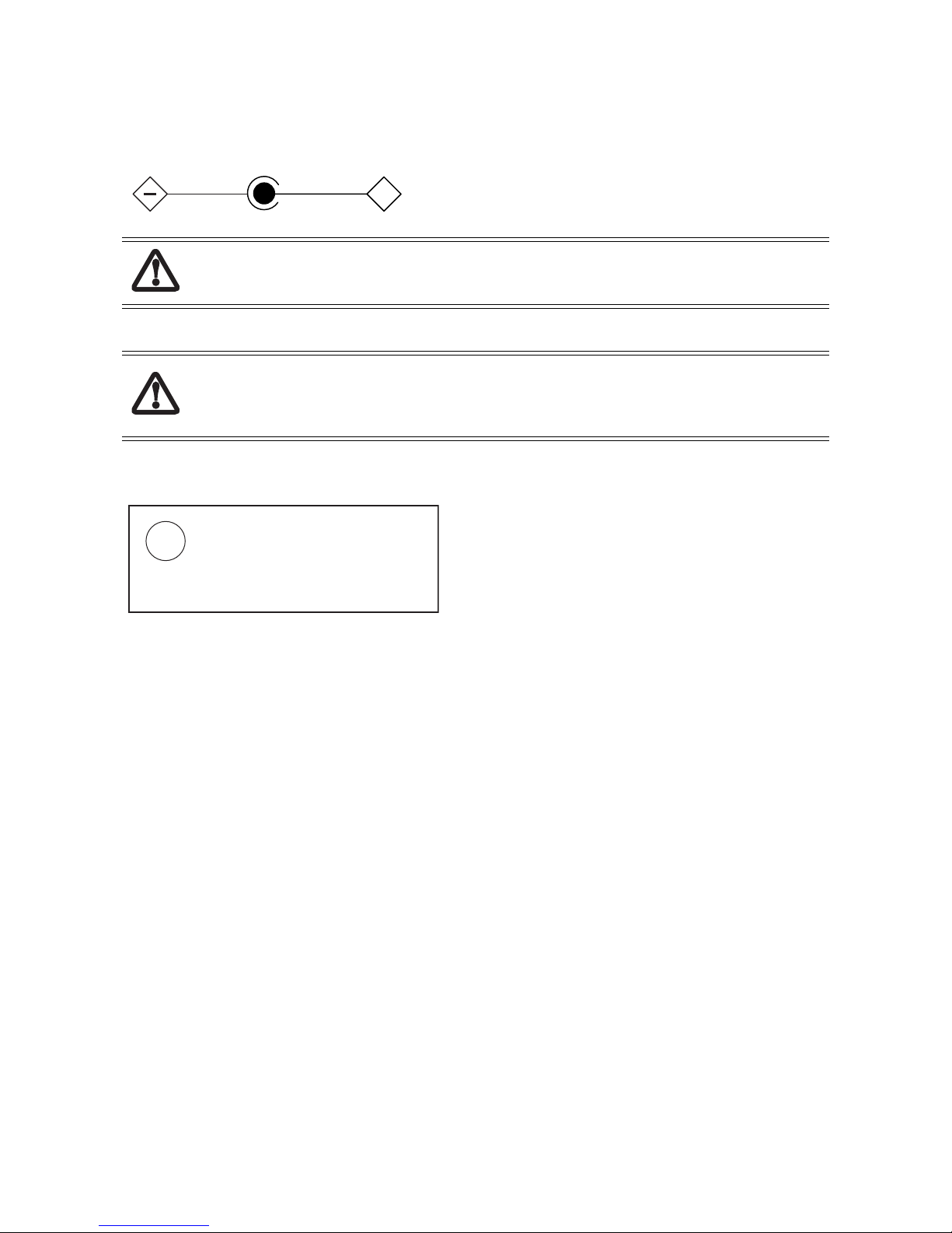
UL Notice
This unit requires an AC adapter to operate. Use only UL Listed Class 2 Adapters with an output rating of 16 VDC, with a current of 3.75 A.
AC Adapter output polarity:
+
The modem-to-telephone network connection must be a line cord using a minimum #26 AWG wire.
For Authorized Repair Technicians Only
• For continued protection against risk of fire, replace only with the same type and rating fuse.
• Danger of explosion if Lithium (clock) battery is incorrectly replaced. Replace only with the same or
equivalent type recommended by the manufacturer. Dispose of used batteries according to the
manufacturer’s instruction.
System Disposal
LAMP(S) INSIDE THIS PRODUCT
CONTAIN MERCURY AND MUST
Hg
BE RECYCLED OR DISPOSED OF
ACCORDING TO LOCAL, STATE, OR
FEDERAL LAWS.
71
Page 76

Index
A
AC adapter, specifications 33
ACPI, support for 3
Advanced Configuration
and Power Interface (ACPI) Specification
agency approval, specifications 35
audio inputs and outputs, enabled
and disabled on pen tablet and port replicator
audio jacks, connector, specifications 31
2
B
battery
battery pack, charge status
battery pack, system power hardware and power
management
bridge battery, specifications 33
main battery pack, specifications 33
sub battery 33
BIOS settings
about
6
BIOS Setup
Boot menu options
boot-time diagnostic messages, enabling 24
display screen 7
Exit menu options 27
Info menu 26
Keyboard Features Submenu Options 13
Main menu options 9
Owner Information menu 23
Primary Master submenu 10
QuickBoot mode, enabling 24
Security menu options 20
setup prompt, enabling 24
starting 6
supervisor password, enabling 20
system date, changing 9
system time, changing 9
using 7
BIOS Setup Utility 6
BIOS version, displaying in BIOS Setup 26
boot-time diagnostic messages,
enabling in BIOS Setup
bridge battery 33
48
48
24
24
C
cache, specifications 28
cache, viewing size of in BIOS Setup 26
connectors
42
DC power input, pin assignments 36
CPU speed, specifications 28
CPU speed, viewing in BIOS Setup 26
current BIOS settings 6
D
date, changing in BIOS Setup 9
DC power input 36
connector, pin assignments 36
connector, specifications 49
voltage specifications 31
default settings for BIOS Setup options 27
dimensions 32
DIMM card, removing 51
DIMM slot, specifications 28
display select hotpad and display BIOS option 14
display, external, selecting in BIOS Setup 14
DMI event logging options, BIOS Setup 19
E
environmental, specifications 30
exiting BIOS Setup, exit menu options 27
external video 30
H
hard disk drive
installing
internal, replacing 54
removing 54
specifications 31
hard disk drive port, specifications 45
hardware options, installing 50
headphone jack 42
humidity, specifications 30
55
I
I/O controller, specifications 28
IEEE 1394 Jack 31
info menu, in BIOS Setup 26
installing the hard disk drive 55
installing the internal hard disk drive 54
internal LAN/modem 3
specifications 34
IrDA port, specifications 31, 37
IrDA standards 2
Index-72
Page 77

L
LAN/modem, internal, See also
internal LAN/modem
Language 9
level 1 cache, viewing size of in BIOS Setup 26
level 2 cache, viewing size of in BIOS Setup 26
3
M
memory
DIMM slot, specifications
video memory, specifications 28
viewing size of in BIOS Setup 26
memory module 51
Microphone 42
Microsoft Developer’s Network 2
Microsoft Windows XP Professional Resource Kit 2
Microsoft Windows XP Tablet PC Edition 4
28
O
organization of this manual 1
P
password on boot, BIOS option 21
passwords, in BIOS Setup 20
PC 5
PC Card
PC Card Standards, related documentation
slots, specifications 31
support 3, 5
PC Card port, specifications 43
PC2001 design guidelines 3
PCIC protocol 3
Pen Support 4
peripheral interface, specifications 31
peripheral interfaces, on tablet pc 36
permanent BIOS settings 6
physical specifications 32
power management
power management microcontroller unit (PMU)
2
48
power system, specifications 33
states 48
Specifications 28
specifications
AC adapter
agency approvals 35
audio controller 28
battery pack 33
cache 28
DC power input connector 49
DC power input voltage 31
DIMM slot 28
environmental 30
general 28
Hard Disk Drive 28
hard disk drive port 45
humidity 30
I/O controller 28
IEEE 1394 Controller 28
infrared keyboard port 31
Internal modem 34
IrDA port 31, 37
memory 28
Modem Chipset 28
PC Card controller 28
PC Card port 43
physical 32
power management 33
power system 33
processor 28
sub battery 33
tablet dock 35
temperature 30
USB port 31
video memory 28
Stylistic ST5000 Tablet Dock User’s Guide 2
Stylistic ST5000 User’s Guide 2
sub battery 33
Supervisor 21
supervisor password, enabling in BIOS Setup 20
SVGA video mode 30
system date, changing in BIOS Setup 9
system interface port
connector type
system power 48
system time, changing in BIOS Setup 9
33
31
Q
QuickBoot mode, enabling in BIOS Setup 24
R
related documentation 2
removing a DIMM card 51
removing the hard disk drive 54
Replacing/Installing a Wireless LAN Module 52
S
setup prompt, enabling in BIOS setup 24
speaker 42
T
tablet dock, specifications 35
Tablet PC features 3
temperature, specifications 30
the 12
time, changing in BIOS Setup 9
U
Universal Serial Bus, specification 2
USB port, position assignments 37
USB port, specifications, pen tablet 31
Index-73
Page 78

USB port, specifications, tablet dock 35
user password, enabling in BIOS Setup 20
V
video memory, specifications 28
video modes supported for use with external monitor 30
video, external 30
X
XVGA video mode 30
Index-74
 Loading...