

Page 1
Page 2

Fujitsu Personal Systems, Inc. has made every effort to ensure the
accuracy and completeness of this document; however, because ongoing
development efforts are made to continually im prove the capabilities of
our products, we cannot guarantee the accuracy of the contents of this
document. We disclaim liability for errors, omissions, or future changes
herein.
Fujitsu is a registered trademark of Fujitsu, Ltd.
Stylistic LT is a trademark of Fujitsu Personal Systems, Inc.
MS, MS-DOS, and Microsoft are registered trademarks of Microsoft
Corporation. Windows 98 is a trademark of Microsoft Corporation.
Pentium is a regist ered trademark of In tel Corporation. MMX is a
trademark of I nt el Corporation.
Intellisync is a registered trademark of Puma Technology, Inc.
All other products are trademarks or registered trademarks of their
respective companies.
Copyright 1999
Fujitsu Personal Systems, Inc.
No part of this publication may be copied, reproduced, or translated, without the prior
written consent of Fujitsu Personal Systems, Inc. No part of this publication may be
stored or transmitted in any electronic form without the prior consent of Fujitsu
Person al Sys tem s, Inc.
Page 3
Agency Compli an ce
Warnings and Cautions 0
Warnings and Cautions that appear in this manual should be closely heeded.
Warnings represent situations that are potentiall y harmful to the user. Cautions
represent situations that can cause physical damage to the system or other
equipment.
UL Notices 0
Cautions
• For continued protection against the risk of fire, replace
only with the same type and rating of fuse.
• There is a danger of explosion if the CMOS battery is
incorrectly replaced. Replace only with the same or
equivalent type recommended by the manufacturer.
Dispose of used batteries according to manufacturer's
instruction.
• Changes or modifications not expressly approved by
Fujitsu Personal Systems, Inc. could void this user’s
authority to operate the equipment.
Warnings
• The CMOS battery may explode if mistreated. Do not
recharge, disassemble, or dispose of in fire.
• For spare battery packs, order only Fujitsu Models
FMW29BP1 (6-cell) or FMW29BP2 (3-cell).
• To charge battery packs FMW29BP1 or FMW29BP 2
externally, use only a Stylistic LT
charger FMW51BC1
.
TM
external battery
iii
Page 4
FCC Notices 0
DECLARATION OF CONFORMITY
according to FCC Part 15
Responsible Party Name:
Address:
Fujitsu Personal Systems, Inc.
5200 Patrick Henry Drive
Santa Clara, CA
Telephone:
Declares that product:
408-982-9500
Model: Stylistic LT
Complies with Part 15 of the FCC Rules
This device complies with Part 15 of the FCC rules. Operation is subject to
the following two conditions: (1) This device may not cause harmful
interference, and (2) this device must accept any interference received,
including interference that may cause undesired operation.
David Woo - Mgr. Agency Compliance May 28, 1999
Full Name / Title Date
Note: The Stylistic LT is available in a number of different configurations, as delineated
in the following table. For more detailed information about the FCC rules and their
applicability to the Stylistic LT pen tablet, refer to Appendix A of this document.
Screen Type Modem? LAN? Cord Type Part Number
TFT NO NO US FMW2900TA01
TFT YES NO US FMW2901TA01
TFT NO YES US FMW2902TA01
TFT NO NO UK FMW2900TB01
TFT NO YES UK FMW2902TB01
TFT NO NO EURO FMW2900TC01
TFT NO YES EURO FMW2902TC01
CTF NO NO US FMW2900FA01
CTF YES NO US FMW2901FA01
CTF NO YES US FMW2902FA01
CTF NO NO UK FMW2900FB01
CTF NO YES UK FMW2902FB01
CTF NO NO EURO FMW290OFC01
CTF NO YES EURO FMW2902FC01
iv
Page 5

Table of Contents
Warnings and Cautions ............................................................................. iii
UL Notices.................................................................................................... iii
FCC Notices................................................................. .... ............................ iv
Chapter 1
Getting Started
Included with the Stylistic LT Pen Tablet ............................................... 1-1
Optional Accessories................................ .... ... ................................. .... ... ... 1-2
Stylistic LT Pen Tablet Features................................................................ 1-3
Status Indicators.......................................................................................... 1-6
Connectors and Peripheral Interfaces..................................................... 1-9
Chapter 2
Using the Stylistic LT Pen Tablet
System States............................................................................................... 2-1
Using the Pen............................................................................................... 2-3
Using Hovering Mode.................................................................... 2-3
Starting the Pen Tablet ............................................................................... 2-4
Using the Security Card............................................................................. 2-4
Shutting Down the System........................................................................ 2-7
Suspending System Operation.................................................................. 2-7
Resuming System Operation..................................................................... 2-9
Using Hotpads............................................................................................. 2-10
Charging the Battery Pack......................................................................... 2-12
Removing and Installing the Battery Pack.............................................. 2-13
Conserving Battery Power ......................................................................... 2-15
Modem Connection.................................................................................... 2-16
LAN Connection......................................................................................... 2-17
PC Card Slots............................................................................................... 2-18
Chapter 3
Care and Maintenance
Protecting the Display Screen ................................................................... 3-1
Storing the Stylistic LT Pen Tablet............................................................ 3-2
Protecting the Stylistic LT Pen Tablet in Harsh Environments............ 3-3
Avoiding Overheating............................................................................... 3-3
Cleaning the Display Screen...................................................................... 3-3
Calibrating the Pen ..................................................................................... 3-4
Replacing the Pen........................................................................................ 3-5
Solving Problems........................................................................................ 3-6
System Will Not Resume Operation ............................................ 3-6
Display Screen Is Blank or Difficult to Read............................... 3-6
Infrared Data Transfer Is Not Working....................................... 3-7
Pen Tablet Is Not Responding to the Pen.................................... 3-7
Cursor Is Not Tracking Pen........................................................... 3-7
v
Page 6

Audio Volume Is Too Low............................................................ 3-8
Configuring Peripherals In ter fac es..................................... ......... 3-8
Chapter 4
Using the O ptional Peripherals
Stylistic LT Mini-Dock................................................................................ 4-1
Installing the Stylistic LT into the Mini-Dock............................. 4-4
Removing the Stylistic LT from the Mini-Dock.......................... 4-5
Stylistic LT Charge-Only Dock ................................................................. 4-5
Installing the Stylistic LT into the Charge-Only Dock .............. 4-6
Removing the Stylistic LT from the Charge-Only Dock........... 4-6
Stylistic LT Wireless Keyboard................................................................. 4-7
Using the Wireless Keyboard........................................................ 4-7
Entering an Identification Code................................................ 4-8
Encountering Problems when Using the Wireless Keyboard 4-8
Replacing the Wireless Keyboard Batteries ............................ 4-9
Appendix A
Agency Notices
FCC Notices..................................................................... .... ........................ A-1
Notice to Users of Radios and Television.................................... A-1
Notice to Users of the U.S. Telephone Network......................... A-1
DOC (Industry Canada) Compliance Not ic es.................... ... ................. A-3
Notice to Users of Radios and Television.................................... A-3
Notice to Users of the Canadian Telephone Network............... A-3
Avis Aux Utilisateurs Du Réseau Téléphonique Canadien...... A-4
vi
Page 7

Chapter 1
Getting Started
The Stylistic LT™ pen tablet is a high-performance, pen-based computer that is
designed to operate under Windows 98. This chapter provides an overview of the
Stylistic LT pen tablet and its features.
Included with the Stylistic LT Pen Tablet 1
The following items are included with the Stylistic LT pen tablet:
• Stylistic LT pen
• Stylistic LT 3-cell battery pack
• AC adapter
• Screen protectors (quantity: 2)
• Hard disk drive with Windows 98 operating system installed in the pen tablet
• Microsoft Windows 98 operating system user’s guide with certificate of
authenticity for operating system software
• Certain Stylistic LT models are equipped with either an optional internal 56 Kbps
†
modem*
* The 56 Kbps rate is nominal; due to FCC restrictions, actual rates are limited
to 53 Kbps.
†
or an optional internal LAN card.
The internal modem is available as an option in North America only.
1-1
Page 8

Optional Accessories 1
The following optional accessories can be used with the Stylistic LT pen tablet. Refer
to the instructions provided with these accessories for details on th eir use.*
• Auto Adapter FMWCB2
• Mini-Dock FMW29PR1*
• Charge-Only Dock FMW29CR1*
• External Floppy Disk Drive FMWFD2
• Wirele ss Keyboard*:
• North America - FMWKB4A
• United Kingdom -FMWKB4B
• Germany - FMWKB4D
• France - FMWKB4F
• Holster A FMWCC34
• Holster B FMWCC37
• Folding Desk Stand FMWDS 3
• Compact Desk Stand FMWDS4
• Carrying Case FMWCC38
• Harsh Environment Case FMWCC39
• Portfolio Case FMWCC40
• Slipcase FMWCC41
• Battery Pack (3 cell) FMW29BP2
• Battery Pack (6 cell) FMW29BP1
• External Battery Charger FMW51BC1
• Screen Protectors (package of 12) FMWSP8
• Pen (package of 5) FMW29PN1
• Security Card (package of 10) FMW29SC1
* Instructions for use of the Stylistic LT mini -dock, the charge-only dock, and
the wireless keyboard are also included in Chapter 4 of this manual;
instructions for the other options are shipped with the individual peripherals.
1-2
Getting Started
Page 9

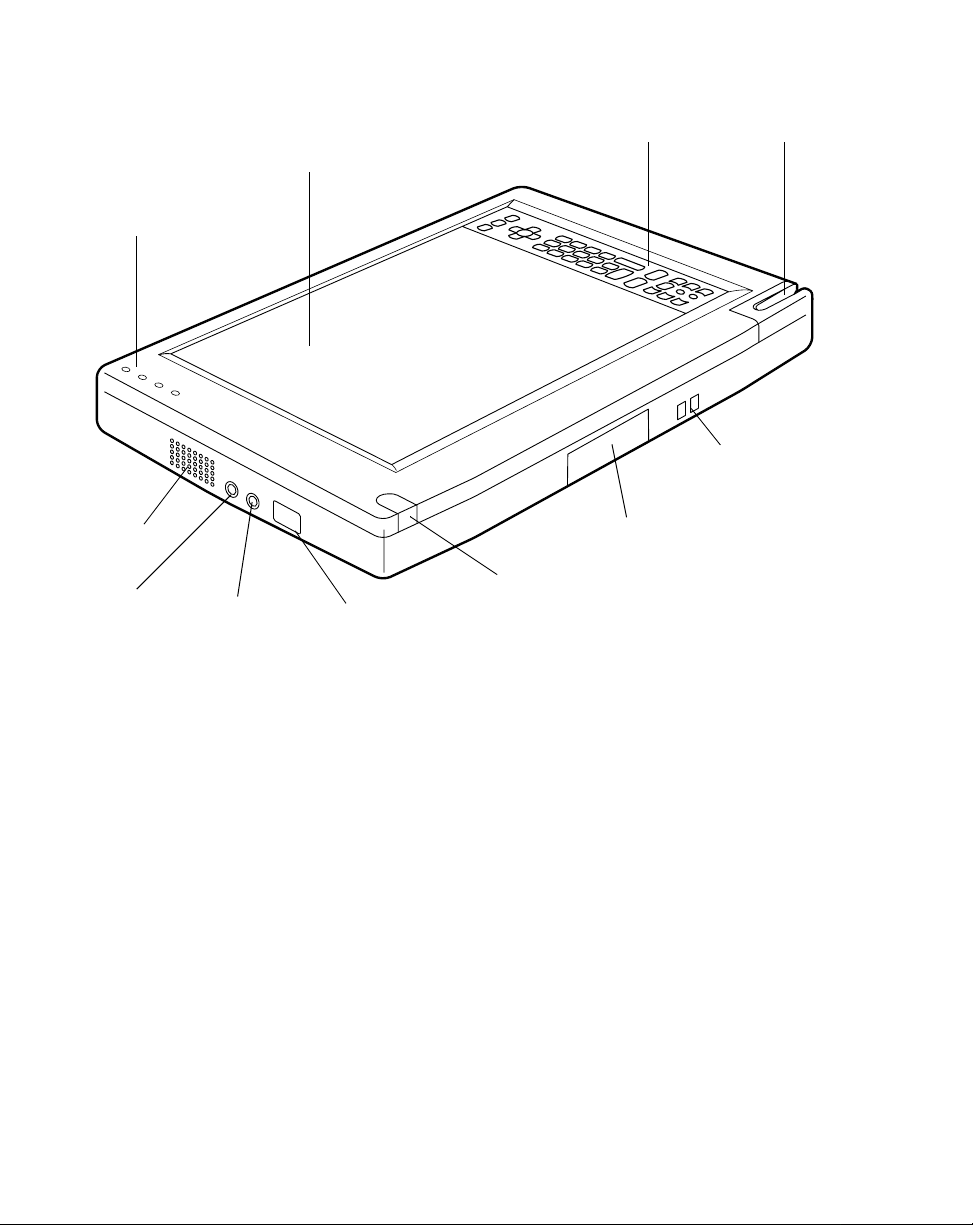
Stylistic LT Pen Tablet Features 1
Features and controls that you use to operate the Stylistic LT pen tablet are described
briefly below and illustrated in Figures 1-1 and 1-2. Details on using these features
and controls are provided later in this manua l.
Front and Side Features (Figure 1-1): 1
• Display: Provides an area where you read information and enter data with the
pen.
• Status Indicators: Indicate the pen tablet’s power status, battery charge level,
hard disk access, and hovering state. Reference Chapter 2 for additional
information on the hovering state.
• Pen: Acts as the main pointing device that you use to run programs and enter
data. A pen holder is built into the pen tablet to store the pen when not in use.
• Speaker: Allows you to play back audio files monaurally witho ut external
hardware.
• Microphone Jack: Allows you to connect an external microphone*.
• Headphone Jack: Allows you to connect stereo headphones*.
• Infrared I/O Port: Provides an infrared interface for comm uni cat ion wit h devices
compliant with IrDA Standard Revision 1.1.
• Wireless Keyboard Infr ared Port: Provides an infrared interface for
communication with the optional wireless keyboard*. Refer to Chapter 4 of this
manual for instructions on using the keyboard.
• Hotpad Area: Contains several keys that allow you to change settings for the
display and speaker, and to allow emulation of a right mouse button. The hotpads
also let you select hovering mode and to Save-to-Disk by tapping with the pen.
• Mini-Dock Connector: Allows you to install the Stylistic LT in an optional
mini-dock* for enhanced connectivity. Refer to Chapter 4 of this manual for
instructions on using the mini-dock.
• Charging Contacts: Provide power to the system when installed in either the
mini-dock* or charge-only dock*.
.
Refer to Chapter 4 of this manual for
instructions on using the charge-only dock.
* These peripherals and accessories are sold separately.
Stylistic LT Pen Tablet Features
1-3
Page 10
Status
Indicators
Speaker
Headphone
Jack
Hotpad Area
Display
Mini-dock
Microphone
Jack
Infrared
I/O Port
Wireless
Keyboard
Infrared Port
Connector
Figure 1-1 Stylistic LT Pen Tablet Features (Front View)
Pen Holder
Charge-only
Contacts
Rear and Side Features (Figure 1-2): 1
• DC Input Connector: Allows you to connect the AC adapter or auto adapter.*
• Removable Battery Pack: Provides power to the system when not connected to
AC power.
• Battery Latch: Secures the removable battery pack when it is installed in the
system.
• Suspend/Resume Button: Allows you to suspend or resume system operation in
order to optimize battery lif e.
• Reset Button: Restarts the pen tablet in the event of system difficulty. Note that
pressing this button results in loss of active data.
* These peripherals and accessories are sold separately.
1-4
Getting Started
Page 11
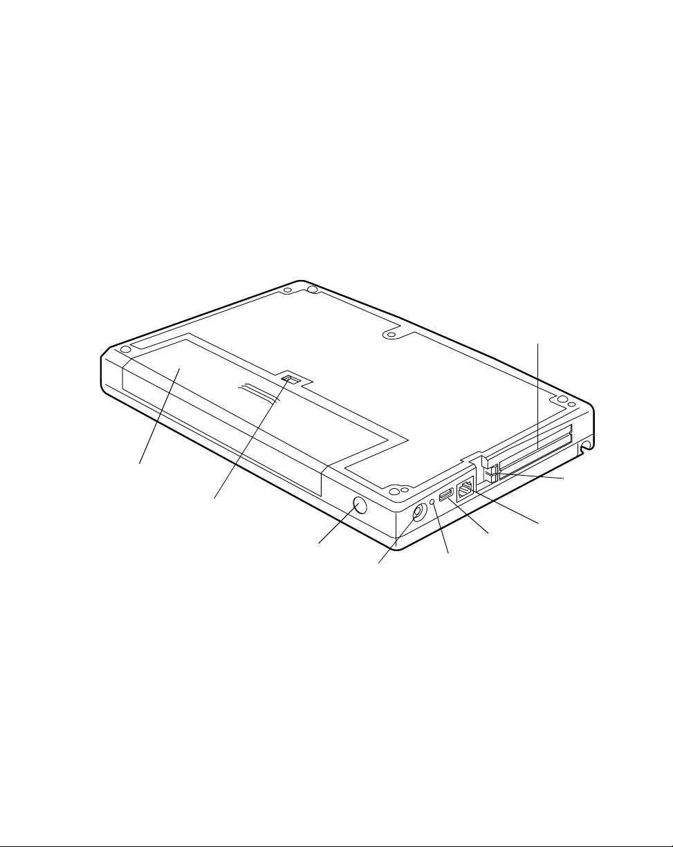
• PC Card Door: Allows you to access PC Cards* installed in the PC Card slots.
Note that Slot 2 is closest to the display.
• Eject Buttons: Allow you to eject a PC Card from a PC Card slot.
• USB Port: Allows you to connect Universal Serial Bus-compliant devices to the
pen tablet.
• Modem Port
†
: Allows you to connect a standard RJ-11 telephone plug to the pen
tablet’s optional internal modem.
* These peripherals and accessories are sold separately.
Removable
Battery Pack
Battery
Latch
Suspend/Resume
Button
DC Input
Reset
Button
USB
Port
PC Card
Slots
Modem
Port
Eject
Buttons
†
Figure 1-2 Stylistic LT Pen Tablet Features (Rear View)
†
The modem port is found only on those systems containing an internal modem.
The internal modem is available as an option in North America only.
Stylistic LT Pen Tablet Features
1-5
Page 12
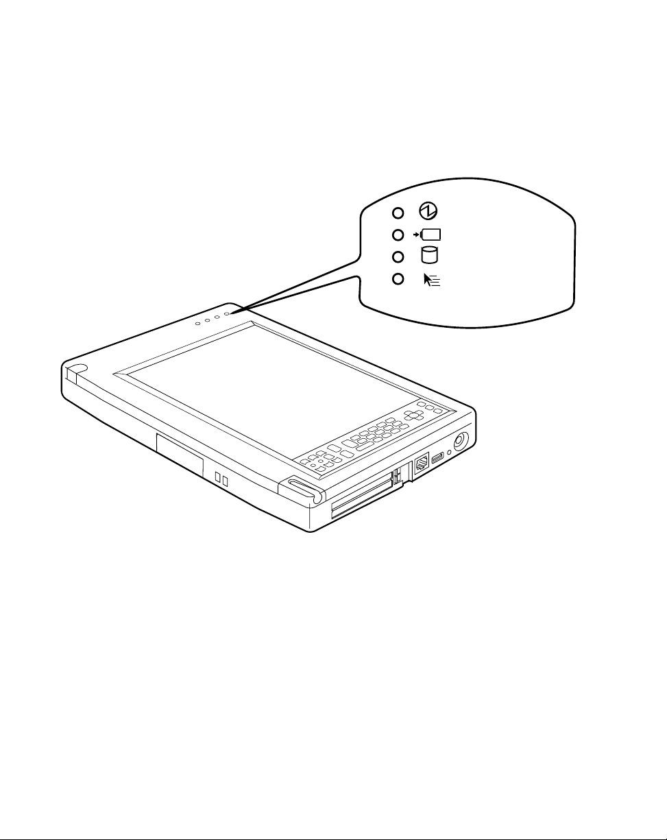
Status Indi cators 1
Icons appear in the Status display indicating the status of system functions such as
system power and battery charge level. The locati on of icons in the Status indicator
section is shown in Figure 1-3.
(Power)
(Charging)
(HDD Access)
(Hovering/
Security)
1-6
Figure 1-3 Status Indicator Icons
Getting Started
Page 13
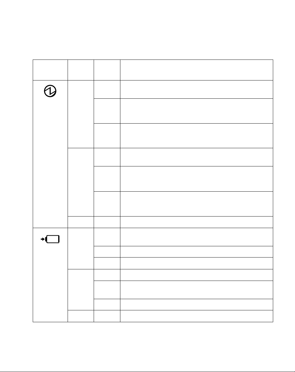
Table 1-1 shows how the LEDs associated with the individual icons are displayed,
and describes what the variations of that display indicate. (If an icon LED is not lit, it
indicates that the related system function is off or inactive.
Table 1-1 System Status Indications
Icon
Power
Icon
LED
Status
On Green Power On
Blink Green Suspend Mode
Off Unlit Power Off or Save-to-Disk
On Green Charging is complete or running off of AC with no battery
Color System Function
(with battery between 13% and 100%)
Amber Power On
(during short periods when the system is chec king remainin g
battery life)
Red Power On
(with battery at 12% or less charge, or no
battery installed)
(with battery between 13% and 100%)
Amber Suspend Mode
(during short periods when the system is chec king remainin g
battery life)
Red Suspend Mode
(with battery at 12% or less charge, or no
battery installed)
installed.
Charging
Icon
Amber Charging is in process.
Red There is a problem with the battery.
Blink Green ---
Amber Battery temperature out of thermal range; charging has
stopped.
Red ---
Off Unlit No charging in process .
Status Indicators
1-7
Page 14
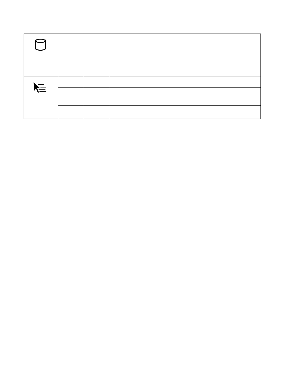
HDD
Access
Icon
Hovering/
Security
Icon
Table 1-1 System Status Indications (Continued)
On Green Displayed when the hard disk drive is being accessed.
Off Unlit Unlit when the hard disk drive is inactive.
On Green Operating in Hovering mode.
Blink Green Awaiting cancellation of security. (This occurs when the
computer is awaiting password input).
Off Unlit Operating in normal mode.
1-8
Getting Started
Page 15
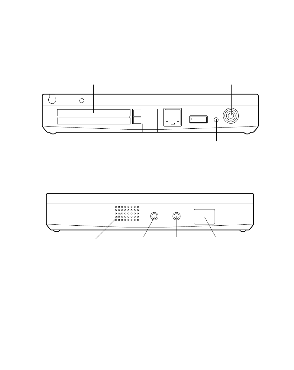
Connectors and Peripheral Inter f a ces 1
Connectors and peripheral interfaces on the Stylistic LT pen tablet allow you to
connect a variety of devices. Figures 1-4 and 1-5 show locations of peripheral
connectors on the pen tablet. Additional features are shown for reference.
PC Card Door
Modem Port (optional)
USB Port
Figure 1-4 Right-Side Connectors and Interfaces
Speaker Headphone
Jack
Microphone
Jack
DC Input
Reset Button
Infrared
I/O Port
Figure 1-5 Left-Side Connectors and Interfaces
Connectors and Peripheral Interfaces
1-9
Page 16
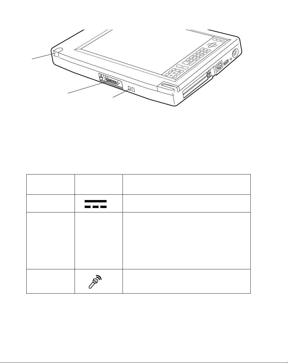
Infrared
Keyboard
Port
Mini-dock
Connector
(cover removed)
Charging
Contacts
Figure 1-6 Bottom Connectors and Interfaces
Table 1-2 provides a description of each peripheral connector and interface on the
Stylistic LT pen tablet. Each of the illustrated icons is embossed on the pen tablet
case.
Table 1-2 Peripheral Connectors and Interfaces
Connector/
Peripheral
DC Input
Connector
Infrared I/O Port No icon An infrared transceiver built into the pen tablet
Microphone Jack Connects an external microphone. The internal
1-10
Getting Started
Pen Tablet Icon Purpose
Connects an ex ternal pow er source such as the A C
adapter or auto adapter.
allows you to communicate with other devices that
are compliant with the IrDA Standard Revision 1.1.
Effective range for infrared communication is about
3 feet, and within 15 degrees off of center. A clear
line-of-sight path must exist between the IrDA port
on the pen tablet and the IrDA transceiver on the
other device.
microphone is disabled when you plug in an
external microphone.
Page 17
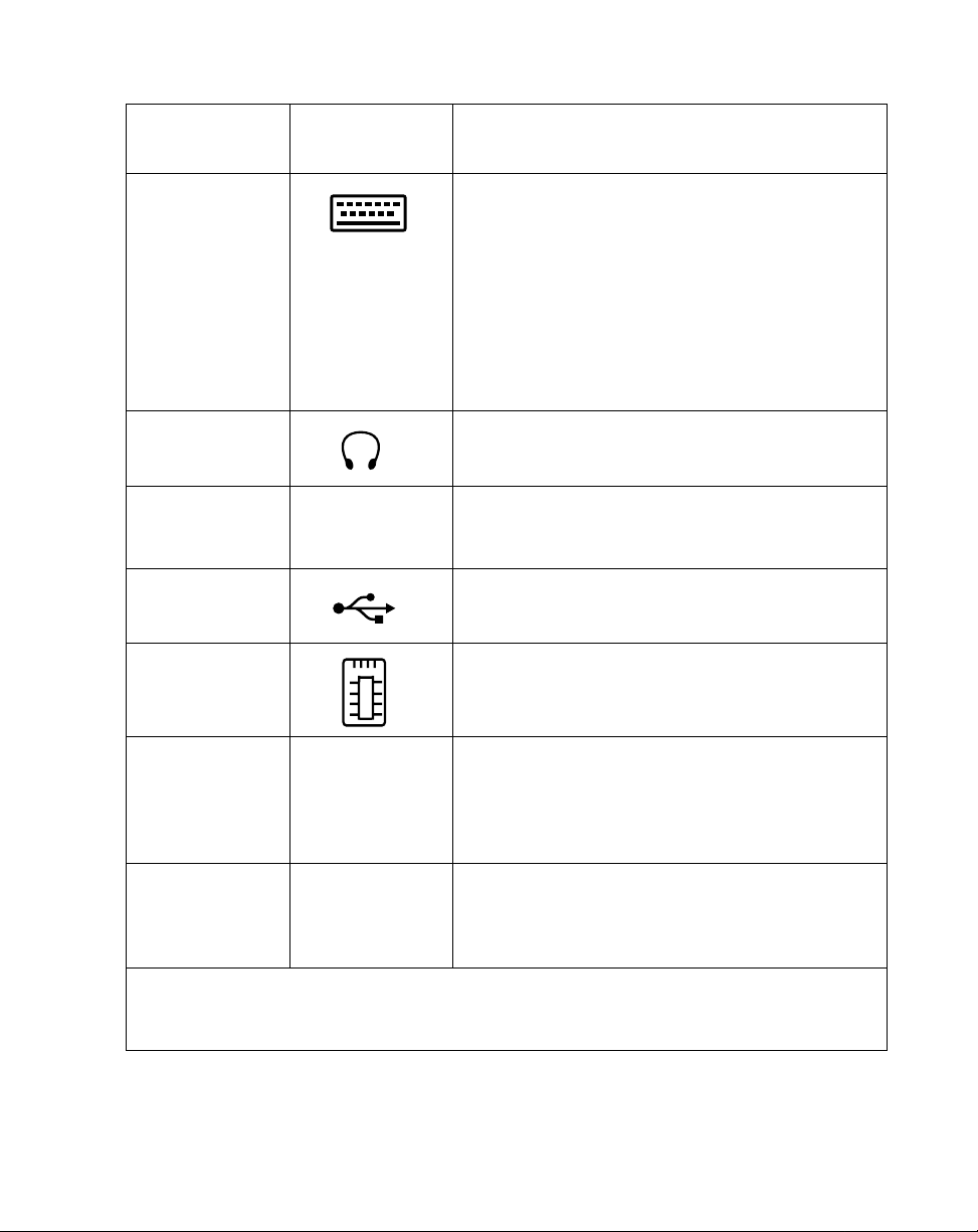
Table 1-2 Peripheral Connectors and Interfaces
Connector/
Peripheral
Wireless
Keyboard
Infrared Port
Headphone Jac k Connects ste r eo hea dph one s or po wered external
Mini-dock
Connector
USB Port
PC Cards
*
Pen Tablet Icon Purpose
An infrared receiver built into the pen tablet allows
you to communicate with a wireless infrared
keyboard. The keyboard infrared port works
optimally between 10 to 30 cm (app roximately 4 in.
to 12 in.) from the keyboard infrared port, located
on the bottom edge of the pen tablet. Ensure that
there is a clear line-of-sight path between the
infrared receiver on the pen tablet and the infrared
transmitter on the keyboard. Refer to Chapter 4 for
more information on the wireless keyboard.
speakers.
No icon Connects the Stylistic LT mini-dock or other
approved docking device. Refer to Chapter 4 for
additional information about the mini-dock.
Connects Univers al Seria l Bus-c ompliant devices
to the pen tablet.
Two Type II PC Cards or one Type III PC Card can
be installed in the PC Card slots.
Modem Port No icon This port location is used to connect a telephone
line to the optional internal modem using a
standard RJ-11 telephone plug. Note that the
modem is available only in North American
systems.
Charging
Contacts
* To avoid damaging the pen tablet or your peripheral device, shut down the system or
suspend system operation before connecting or disconnecting a peripheral device to this
port.
No icon The charge-only contacts are used when the pen
tablet is installed in either the optional mini-dock or
charge-only dock. Refer to Chapter 4 for more
information on the mini-dock and charge-only dock.
Connectors and Peripheral Interfaces
1-11
Page 18

1-12
Getting Started
Page 19

Chapter 2
Using the Stylistic LT P en Tablet
This chapter covers the fundamental concepts, basic system operation and use, and
system functions of the Stylistic LT pen tablet. You should familiarize yourself with this
information before you attempt to operate the system.
System States 2
Before you begin using the Stylistic LT pen tablet, review the different system states (or
modes) that the pen tablet can use. Being familiar with these system states will help you
determine whether it is appropriate to turn on, resume, suspend, or shut down the
system when you begin a new session or end your current session. System behavior for
each system state is described briefly in the following, with each system s tate listed in
decreasing order of power usage:
• Fully On (normal) state
The system is running and the display screen is on. The system responds to the pen
or other input.
• Idle and Standby states
Some system functions are regulated or turned off to conserve power . The display
screen may be turned off. The system return s to the Fully On state when pen activity
or other input is detec t ed.
• Suspend Modes: When you press the Suspend/Resume button, the system will
either go into Suspend-to-RAM mode, or Save-to-Disk mode. The mode the
system enters was determined when the system was configured -- usually by the
reseller who sold you the pen tablet or by your IS department. Contact one of
those individuals for more information on how your pen tablet is configured.
▲
Suspend-to-RAM mode
When the Suspend option is set, data is saved to system RAM when th e
Suspend/Resume button is pressed.
▲
Save-to-Disk mode
When Save-to-Disk is set (or when the Save-to-Disk hotpad key is tapped),
data is written in the Save-to-Disk area on the hard disk.
2-1
Page 20

• Off state
All system functions are turned off to conserve power . The system does not respond
to the pen or other input. The system boots at the next system power-on.
Your system may be configured to enter some of these states automatically after a
period of inactivity to conserve battery power.
When you use the Stylistic LT pen tablet, you can change the current system state in a
number of ways, depending on which state the system is in. To determine the current
system state, observe the Power icon in the Status display. Table 2-1 gives the
different system states represented by the Power icon and describes how you can
change the system state from the current state.
Table 2-1 Changing System States
Power Icon
Appearance
Power icon
displayed
continuously
Power icon
blinking
Po wer ico n not
displayed
Information in Table 2-1 is supplied to help you understand which system states your system
*
can enter from the current system state. Refer to the procedures on star ting the system,
shutting down the system, suspending system operation, and resuming system operation
given later in this chapter for details on changing the current system state.
†
Your system may be configured to use either Suspend-to-RAM mode, Save-to-Disk mode, or
may use both modes sequentially.
Current State
Fully On,
Idle,
or
Standby
Suspend-to-RAM
Off or
Save-to-Disk
†
To Change State
To turn the system off, shut down the system using
a software shut down.
T o enter the Suspend-to-RAM or Save-to-Disk
suspend system operation using either a hardware or
software suspend, or tap the Save-to-Disk hotpad.
†
To turn the system on, re sume syst em op er ation by
pressing the Suspend/Resume button.
To turn the system off, resume system operation,
then shut down your sy ste m.
T o turn the system on, start your system, or resume
system operation.
*
†
state,
2-2
Using the Stylistic LT Pen Tablet
Page 21

Using the Pen 2
Caution
The Stylistic LT pen can be damaged if used i mp rope rly. Treat
the pen as you would any writing instrument. Observe the
following guidelines for proper pen handling:
• The pen tip is spring-load ed to provide writing c omfort and to
prevent screen damage. Avoid tapping it on surfaces other
than the pen tablet screen.
• To prevent pen loss or damage, it should be stored in the
pen holder when not in use.
You can use the pen to select items and run programs on the Stylistic LT pen tablet like
a mouse on a desktop computer. Programs that support handwriting recognition also
allow you to write characters directly on the screen with the pen. You can also use the
pen as a drawing tool if your program provides a drawing or inking area on the screen.
The screen reacts with the pen when the pen tip touches the screen. The pen tip
generally corresponds to the left button on a two-button mouse. In order to emulate a
right mouse button, tap on the right mouse button on the keypad. The pen tip
automatically returns to left mouse button mode when the screen is tapped again.
For more information on using the hotpads, refer to the “Using Hotpads” section
later in this chapter.
Here are some hints that may help you use the pen more effectively.
• To move the cursor , hold the pen tip lightly on the display screen and move the pen.
• To start a program, double-tap the pen tip (tap the pen tip twice rapidly) on the
program icon as you would double-click a mouse.
• To select an object, tap the pen tip once on the object.
• To drag an object, place the pen tip directly over the object, then press and hold the
pen tip against the display screen while you move the pen.
Note: Installing or ejecting a PC Card while the pen is touching the screen could result in
pen recognition failure. If this occurs, suspend and resume system operation one or
more times, until the pen again becomes operational.
Using Hovering Mode 2
Selecting the Pen Hovering icon on the Stylistic LT keypad provides the user with
better cursor control. When the hovering option is enabled, the cursor can be
Using the Pen
2-3
Page 22

positioned over an icon without activating it. This is useful when you are performing
procedures that require accurate cursor positioning, such as when simulating mouse
rollover, selecting a small icon, or beginning a paint session.
• T o enable hovering, tap the Pen Hovering icon on the keypad. The Hovering system
status indicator light illuminates green when hovering is selected.
• To disable hovering, tap the Pen Hovering icon again. The Hovering system
indicator light is off when hovering is not selected.
Starting the Pen Tablet 2
Follow the procedure below to start the Stylistic LT pen tablet. Before you begin,
confirm that the system is off. To do so, observe the Status display. If the Power icon
is not lit in the Status display, the system is off and it is safe to perform this
procedure. If the Power icon is lit (either blinking or on continuously), do not
perform this procedure. See “System States” earlier in this chapter for details on
operational modes represented by the Power icon.
1. Press the Suspend/Resume button to start the system.
2. Ensure that the battery pack in your pen tablet is sufficiently charged, or connect an
external power source such as the AC adapter or auto adapter to your pen tablet. See
“Status Display” in Chapter 1 to determine the percentage of charge r epresented by
the Charging icon in the Status display.
After performing system initialization, the system starts the operating system installed
on the hard disk drive. Once the operating system is running, you can use the system. If
you are prompted to enter your password, refer to the following section entitled “Using
the Security Card”.
Using the Security Card 2
The Stylistic LT can be used with an optional security card that allows you to enter an
exclusive password. This ensures that only authorized persons can access a particular
system and/or its hard disk drive, depending upon the selections made when the
system was configured.
2-4
Using the Stylistic LT Pen Tablet
Page 23

Note: This feature may not be enabled, d epending upon how your system is configured.
Contact either your reseller or your IS depa rtment for more inform a tion on how
your pen tablet is configured.
Card Locat or/Escape hole
ABCDEFG
HIJKLMN
OPQRSTU
VW X Y Z /
*
Card Locator/Enter hole
Figure 2-1 Stylistic LT Security Card
2-2a. 2-2b.
Password
input holes
(A through Z,
*, and / )
2-2c. 2-2d.
Figure 2-2 Using the Security Card
Using the Security Card
2-5
Page 24

When prompted by your Stylistic LT pen tablet to enter a password, perform the
following procedure:
1. Ensure that the system speaker is on. Audible signals are used later in this
procedure.
2. Place the security card on the display screen in a position similar to Figure 2-2a.
Note that the card can be placed anywhere along the edge, as long as it is
positioned with the cut corner facing the upper left.
3. Hold the card firmly against an edge of the screen frame. With your pen, tap the
Card Locator/Escape hole just under the cut corner, as in Figure 2-2b.
• If you hear two beeps in succession, proceed to step 4.
• If you he ar four beeps in succession, return to step 2.
4.With your pen, tap the Card Locator/Enter hole, as in Figure 2-2c.
• If you hear two beeps in succession, proceed to step 5.
• If you he ar four beeps in succession, return to step 2.
Note: Your password is created during system configuration. To determine your
password, check with y our system administrator or supervisor.
5.Tap in your password using the password input holes, as in Figure 2-2d. Up to
seven characters can be used for a password (inc luding letters and symbols). If
you make a mistake while entering your password, tap the Card Locator/Escape
hole, and repeat steps 2 through 4.
6.After entering your password, tap the Card Locator/Enter hole.
7. If you enter the wrong password, you receive a Setup Warnin g message. If this
occurs, tap Continue and return to step 2.
Notes: • If you have difficulty entering a password, or you move the security card while
entering the password, tap the [Esc] key on the keypad until the hovering/
security LED stops blinking. At that point, begin the input procedure again.
• If you enter the incorrect password three times in a row, you receive a System
Disabled message, and access to the computer is disabled. If this happens, press the
reset switch to r estart the comput er.
2-6
Using the Stylistic LT Pen Tablet
Page 25

Shutting Down the System 2
Follow these steps to shut down and turn off your system:
1. If system operation has been suspended, resume system operation. See “Resuming
System Operation” later in this chapter for details.
2. Save your work and close all running programs.
3. Choose Shut D own from the W indows 98 Sta rt menu and car ry out the Shut Down
command.
The system is now in the Off state.
Suspending Syste m Oper ati on 2
The Stylistic LT pen tablet allows you to suspend the system operation without closing
programs or exiting the operating system. Use this feature to conserve battery power
when a system shutdown is inconvenient. There are two different suspend modes:
Suspend-to-RAM and Save-to-Disk. In Suspend-to-RAM mode, active data is saved
by maintaining power to RAM while most other system components are powered
off. In Save-to-Disk mode, active data is stored on the hard disk drive and power
usage is reduced to the same level used in the Off state.
To suspend system operation, perform one of the following procedures:
• Press the Suspend/Resume button, or carry out the Suspend command fr om your
operating system or power management program. (If your system is configured to
suspend operation using Save-to-Disk mode, which is explained later in this
procedure, a message is displayed while data is saved to your hard disk.)
• Tap the Save-to-Disk hotpad key.
Caution
If you are replacing the battery pack,
remove the battery pack. Failure to do so may result in loss of your unsaved
data.
The Power icon blinks when system operation is suspended-to-RAM, and is off
when saved-to-disk. The state your system enters is dependent upon how your
system is configured. At this point, programs that were running are stopped,
active data is saved, and the system enters one of two different low-power states,
or suspend modes, as explained in the following paragraphs.
be sure to Save-to-Disk
Shutting Down the System
before you
2-7
Page 26

4. Observe the Power icon in the Status display to determine which suspen d mode
your system is using.
• Power icon is blinking: Suspend-to-RAM mode
In this mode, active data is saved by maintaining power to RAM while most
other system components are powered off. The Power icon in the Status display
indicates the battery charge level. A fully charged 3-cell battery pack can
maintain data in RAM for approximately 7 days; a fully charged 6-cell battery
pack can ma intain data for approxim ately 14 days . A partially ch arged bat tery
pack will maintain data in RAM for proportionately less time.
• Power icon is not displayed: Save-to-Disk mode
In this mode, active data is stored on the hard disk drive and po wer usage is
reduced to the same level used in the Off state. When the system is in
Save-to-Disk mode, the Power icon is not visible in the Status display. In thi s
mode, there is no danger of losing data if battery power is lost.
If you have successfully performed this procedure, system operation is now suspended.
Refer to “Resuming System Op eration” later in this chapter to resume system operation.
Also, note the following with regard to suspending system operation:
• Y ou can remove the battery pack while the system is in Save-to-Disk mode, but not
Suspend-to-RAM mode (unless the AC adapter is connected). To prevent losing
unsaved data, always perform Save-to-Disk before you remove the battery pack.
• Y our system may be configured to suspend operation automatically after a period of
inactivity.
• Your system may be configured to enter Save-to-Disk mode automatically after a
period of time in Suspend-to-RAM mode.
• The system uses a small amount of battery power when in Suspend-to-RAM mode.
Eventually, the battery will become fully discharged.
Note: If you will not be using the system for an extended period of time, shut down the
system rather than using Suspend-to-RAM mode.
• If the battery pack charge drops to the Low-Battery Warning level while the system
is running, the Power icon will turn red and blink intermittently. If this occurs,
suspend system operation, shut down the system, or attach an external power
source, such as the AC adapter, to the pen tablet.
• If the battery charge drops to the Critically Low level while the system is running,
the system is forced into Suspend-to-RAM mode. If this occurs, you must connect an
appropriate external power source such as the AC adapter before you can resume
2-8
Using the Stylistic LT Pen Tablet
Page 27

system operation. (If the battery charge drops to the Critically Low level while the
system is in Suspend-to-RAM mode, the system stays in Suspend-to-RAM mode.)
• Suspending system operation interrupts da ta communications; however, some
programs may block the system from suspending to prevent an interruption.
• The Suspend/Resume button on your system may be configured during system
setup to act as an On-only button. If this is the case, pressing the Suspend/
Resume button will not suspend system operation as described here. Contact
your IS department or reseller if your system configuration is not suitable.
• If your system is equipped with a PC Card that allows you to connect to a wired or
wireless network, you may be logged off the network after a period of inactivity
while system operation is suspended. Contact your network administrator or local
help desk for details on log-off parameters for your network.
Resuming System Operation 2
To resume system operation, (from either Suspend-to-RAM or Save-to-Disk modes),
press the Suspend/Resume button.
• From Suspend-to-RAM mode
After a few seconds, the system returns to the Fully On state and system operation
resumes. Note that the display turns on shortly before the pen becomes active due to
the power-up sequences observed by the system.
• From Save-to-Disk mode
Active data is read from the hard disk drive, and after 15 to 30 seconds, the system
returns to the Fully On state.
Note that power to several system components must be restored before system
operation resumes. Allow sufficient time for system operation to resume before
attempting to use the system. If your system uses Save-to-Disk mode, it will take
longer to resume operation as compared to using Suspend-to-RAM mode. Time is
needed to read data from the hard disk drive.
Use the system as you normally would once system operation resumes.
All programs resume at the point where execution stopped when system operation was
suspended.
Resuming System Opera tion
2-9
Page 28

Using Hotpads 2
The Hotpad area consists of several pen-active “keys” on the rig ht si de of the system
display that you can use to change several settings. The hotpads allow you to:
• Adjust the display and speaker settings
• Invoke right mouse button
• Invoke hovering capability
• Use as a numeric pad
• Generate a Save-to- Disk request
To use a hotpad key, tap directly on it with the pen. You can also press and hold the
pen tip against the Volume, Contrast, and Brightness hotpad keys to automatically
repeat the hotpad function. The location of each hotpad key is shown in Figure 2-3.
Display Key
Escape
Key
ESC
7
456
123
0
Mouse
Right
Button
Key
Brightness
Keys
SPACE
Figure 2-3 Stylistic LT Hotpad Arrays
Save-to-
Save-toDisk Key
Disk Key
Cursor
Keys
BSTAB
9
8
Numeric
Keys
Hovering
Key
Speaker
Keys
Contrast
Keys
2-10
Using the Stylistic LT Pen Tablet
Page 29

A summary of each hotpad’s function is given below.
Note: Equivalent key codes are included for applicable hotpad keys. These can be used when
a keyboard is connected.
Table 2-2 Hotpad Keys
Icon Name Description
Escape Functions the same as the [Esc] key on a typical
ESC
Display De vi ce Each time the Displa y De vi ce hotpa d k e y i s tapp ed,
Save-to-Disk Starts the Save-to-Disk operation to save data to
Cursor Control Acts in the same way as the cursor keys on a
keyboard.
the display unit is switched (in the following order):
LCD -> CRT -> both LCD and CRT -> LCD...
the disk.
keyboard. (Up, Down, Left, and Right).
0
SPACE
Numeric Keypad Acts in the same way as the numeric keypad on a
BSTAB
keyboard.
998877
654
321
Right Mouse Button Swi tches the pen f unctio n from left mou se b utt on to
right mouse button emulation.
Using Hotpads
2-11
Page 30

Table 2-2 Hotpad Keys
Icon Name Description
Pen Hovering Switches the hovering mode on or off. Throughout
the hovering mode, the hovering/security status
indicator is lit green.
Speaker Volume Down Lowers the speaker volum e.
Speaker Volume Up Increases the speaker volume.
Speaker Volume Mute Toggles the speaker off and on.
Brightness Down Decreases the luminance of the display backlight.
Brightness Up Increases the luminance of the display backlight.
Contrast Down Provides more contrast on CTF models only. This
hotpad has no effect on TFT models.
Contrast Up Flattens the contrast on the CTF models only. This
hotpad has no effect on TFT models.
Charging the Ba ttery P a c k 2
The Stylistic LT battery pack can be charged while it is installed in the pen tablet. To do
so:
1. Connect a DC power source, such as the AC adapter , to the DC input connector on
the pen tablet. The Charging icon appears in the Status display. If the battery pack
charge level is belo w 90%, t he battery pack begins ch ar ging and the Char ging icon
2-12
Using the Stylistic LT Pen Tablet
Page 31

appears in the Status display. If the battery pack charge is 90% or higher when you
connect DC power, the battery pack will not charge; this prevents over charging the
battery pack.
2. Look at the Power icon in the Status display to determine the approximate percent of
charge in t he b attery pack. See “Status Indicators” in Chapter 1 of this manual for
a description of the Power icon.
As long as DC power remains connec ted to the pen tablet, the charging process continues
until the battery pack charge rea ches 10 0%. Ch arg e tim es s how n i n Table 2-3 are for a
fully discharged battery pack charging while the pen tablet is and is not in use.
Table 2-3 Battery Pack Charging Time
Approximate Charge Time
(tablet not in use)
3-Cell 6-Cell 3-Cell 6-Cell
2 hours 3 hours 4 to 6 hours 8 to 12 hours
Approximate Charge Time
(tablet in use)
Also note the following with respect to charging the battery pack:
• You can use the system, suspend system operation, or shut down and turn off the
system without interrupting the charging process; however, using the system while
the battery pack is charging will cause the battery pack to charge at a slower rate, as
noted in Table 2-3.
• As noted in the procedure above, the system will not begin charging the battery
pack if the battery pack charge level is 90% or higher when the system is initially
connected to external DC power. (This prevents the battery pack from being
overcharged.)
• The Stylistic LT battery pack uses lithium ion battery cells which have no
“memory effect.” You do not need to discharge the battery pack before you begin
charging.
Removing and Installing the Battery Pack 2
The battery pack can be removed from the pen tablet and swapped with a charged
battery pack. The battery pack can then be charged in an external charger if one is
available. To remove the battery pack from the pen tablet:
Removing and Installing the Battery Pack
2-13
Page 32

Caution
The Stylistic LT pen tablet does not have a bridge battery.
Prior to removing the battery pack, be sure to save your data
by tapping the Save-to-Disk icon on the keypad or connect an
AC adapter. Save-to-RAM will not suffice, since all data in
RAM is lost when the batter y is removed.
1. Choose one of the following:
• Save your data by tapping on the Save-to-Disk icon on the keypad.
• Close all running programs, then shut down the system.
• Plug in an external DC power source.
2. Slide the battery latch to the unlocked position. (See Figu re 2-4.)
3. Slide the battery pack out of the pen tablet.
If you are using an external battery charger, refer to the instructions provided with the
battery charger.
To install the battery pack, slide the battery pack into the pen tablet until it is firmly
seated. The spring-loaded battery latch automatically clicks into place.
Warning
To prevent pinching your fingers, keep them clear of the area
between the battery pack and the pen tablet when you install
the battery pack.
Once the battery pack is installed, you can start your system and use the system as you
normally would.
2-14
Using the Stylistic LT Pen Tablet
Page 33

Removable
Battery Pack
Battery
Latch
Figure 2-4 Removing and Installing the Battery Pack
Conserving Battery Power 2
You can extend the charge life of your battery pack by conserving battery power. A
fully charged battery pack can run the system under norm al use in most applications
for approximately 2 hours (standard, 3-cell battery pack ) or 4 hours (extended, 6-cell
battery pack). Your results may vary depending on your application and how the
system is configured. Here are some suggestions to help you conserve battery power:
• Use an external power source such as the AC adapter to power the system when
possible.
• Suspend system operation if you won’t be using the system for a few minutes.
• Shut down the system if you won’t be using the system for an extended period of
time.
• Use power management timeouts to help you conserve power automatically.
Conserving Batter y Power
2-15
Page 34

Modem Connection 2
Note: The optional internal 56 Kbps modem installed in some models of the Stylistic LT
pen tablet* has actual transfer rat es of 53 Kbps (receive), 33.6 Kbps ( send), and
14.4 Kbps (fax). Download rates are limited to 53 Kbps in the United States due to
FCC restrictions.
* The internal modem is available as an option in North America only.
The Stylistic LT pen tablet is designed to accept a standard RJ-11 telephone plug.
Connect the plug to the modem jack located on the right of the pen tablet, as shown
in Figure 2-5. The telephone plug can be installed whether or not the pen tablet has
power applied.
If you need assistance configuring the Stylistic LT pen tablet modem, contact your local
help desk or your res eller.
Phone
Jack
2-16
Modem
Plug
Figure 2-5 Connecting the Modem
Using the Stylistic LT Pen Tablet
Page 35

LAN Connection 2
Some models of the Stylistic LT have an internal LAN card that allows the computer
to be connected to a high-speed LAN by 100BASE-TX Ethernet.
Note: An optional Stylistic LT mini-dock (Part Number FMW29PR1) is required in
order to use the LAN option.
1. To use the internal LAN, first shut the system down and unplug the AC Adapter,
if necessary.
2. Install the system into the optional Stylistic LT mini-dock. Refer to Chapter 4 of
this manual for instructions on use of the mini-dock.
3. Connect the AC adapter to the mini-dock, then connect the LAN cable between
the mini-dock and the LAN hub, as shown in Figure 2-6.
Mini-Dock
AC
Adapter
Plug
LAN Plug
LAN Hub
Figure 2-6 Connecting the LAN
4. T o r emove the LAN connector from the mini-dock, press the tab on the plug while
pulling the plug away from the system.
LAN Connection
2-17
Page 36

PC Card Slots 2
The Stylistic LT pen tablet has two PC Card slots that allow you to install up to two
Type II PC Cards using both slots 1 and 2, or a single Type III PC Card using sl ot 1
only. Slot 2 is closest to the screen; slot 1 is closest to the back of the system. See
Figure 2-7 for PC Card slot location.
Notes: • Type II PC Cards will work in either slot, with one exception: zoomed video PC
Cards must be installed in slot 1.
• Some PC Cards require that the system be shut down before installation. Check
the user manual for your particular card before installing it.
To install a PC card, position it with the label facing up and slide it through the PC
card door shutters. When it is properly seated, the eject button will extend away f rom
the computer. Flip the eject button into the eject button tray such that it is parallel
with the system.
To remove a PC Card from a PC Card slot, flip up the adjacent eject button so that it
is perpendicular to the system, then push it in. When the PC Card pops out, carefully
remove it from the slot.
If you need assistance installing a PC Card in the Stylistic LT pen tablet, contact your
local help desk or your reseller.
2-18
Eject Buttons
PC Card
PC Card 2 (upper slot)
PC Card 1 (lower slot)
Figure 2-7 PC Card Slots
Using the Stylistic LT Pen Tablet
Page 37

Chapter 3
Care and Maintenance
This chapter provides pointers on how to care for and maintain your Stylistic LT pen
tablet.
Protecting the Di splay Screen 3
The Stylistic LT pen tablet is designed to provide you with years of service. Using a
screen protector will help ensure that the screen remains as clear as possible. When
installed, the screen protector becomes a durable, replaceable, antiglare writing
surface that protects the display screen from abrasion.
To obtain additional screen protectors use Fujitsu part number FMWSP8 (12-pack)
when ordering. Additional information about installation is included w ith the screen
protectors.
Caution
During normal use of the pen tablet, small particles from the
environment can become embedded in the pen tip and
scratch the screen. To prevent scratching the screen, ensure
that a screen protector is installed before using your pen
tablet. The w a rranty does not cover a sc ree n th at i s sc ra tc hed
as a result of not using a screen protector.
To install a new screen protector on your pen tablet:
1. If a screen protector is already installed on the display screen, remove it before
installing the new screen protector. The screen protector is held onto the di splay
screen surface by a thin strip of adhesive around the edges. A notch in one corner
of the screen protector allows you to slide your fingernail under the screen
protector for easy removal.
2. Clean the adhesive residue from the screen surface by gently wiping the residue
using a soft cotton cloth dampened with denatured alcoho l. Ensure that al l film
has been removed from the screen before applying a new screen protector.
3-1
Page 38

Cautions
• Cleaning the screen surface with denatured alcohol may
result in streaking. If streaking occurs, buff the screen
surface lightly with a soft, dry cloth.
• The Stylistic LT pen tablet is
liquids on the system or wash it with a soaked cloth.
not waterproof
. Do not pour
3. Remove the protective coating from the adhesive side o f the new screen protector
first.
4. Apply the screen protector to the display screen surface. When doing so, orient
the screen protector with the adhesive side of the screen protector facing the
display screen and the notched corner of the screen protector toward the lower
left corner of the display screen.
5. Remove the protective plastic cover from the face of the screen protector.
6. Apply pressure to the screen protector with your finger using a continuous
wiping motion along the edges. The adhesive sets completely within 48 hours. To
ensure a good seal between the screen protector and the display, do not lift the
screen protector from the display once it has been applied.
7. Clean any residue left behind by the protective coating from the exposed surface
of the screen protector by wiping gently with a soft cotton cloth dampened with
denatured alcohol. Wipe the screen protector with a soft dry cloth to remove any
low-tack adhesive; this will help to prevent the pen tip from squeaking.
The screen protector is now installed.
Storing the Stylis tic LT P en Table t 3
Store the Stylistic LT pen tablet in the Fully Off state with a fu lly charged battery
pack installed. The Stylistic LT battery pack always provides power to some system
components, even when the system is in the Fully Off state. If you plan to store the
system with the battery pack removed, be sure to Save-to-Disk prior to storing;
failure to do so could result in lost data. You can store the pen tablet for about 14
days (standard 3-cell battery pack) or 25 days (extended 6-cell battery pack) with a
fully charged battery pack installed. After this period, the batt ery pack s hould be
recharged or replaced with a charged battery pack.
3-2
Care and Maintenance
Page 39

Protecting the Stylistic LT Pen Tablet in Harsh Environments 3
The Stylistic LT pen tablet is designed for use in environments where there is no
direct exposure to rain, mist, sprays, dirt, or other abrasive particles. The optional
Stylistic LT harsh environment case (FMWCC39) and the Stylistic LT screen protector
(FMWSP8) provide some protection in these environments, as well as from physical
damage due to shock or vibration.
Note that the harsh environment case does not render the pen tablet waterproof,
dustproof, or submersible.
The pen tablet is easily used while installed in the harsh environment case. For
additional information on the Stylistic LT harsh environment case as we ll as
additional carrying cases, portfolio cases, and holsters, contact your reseller.
Av oiding Overheating 3
The Stylistic LT pen tablet monitors its internal temperature. As the internal
temperature approaches the tolerable limits of heat-sensitive components, system
functions are automatically limited or turned off to prevent h eat damage.
To avoid overheating the pen tablet, do not charge the pen tablet wh ile it is in the
harsh environment case unless the system is either suspended or off. Using proper
power management techniques while the pen tablet is in the harsh environment case
also helps to prevent overheating.
Cleaning the Disp la y S creen 3
To clean the pen tablet display screen, wipe the screen surface gently using a soft
cotton cloth slightly dampened with water or denatured alcohol. Using dena tured
alcohol may resulting in streaking . If this occurs, gently buff the surface with a soft,
dry cloth.
Caution
The Stylistic LT pen tablet is not waterproof. Do not pour
liquids on the pen tablet or wash the pen tablet with a heavily
soaked cloth.
Protecting the Stylistic LT Pen Tablet in Harsh Enviro nm ent s
3-3
Page 40

Calibrating the Pen 3
You calibrate the pen to adjust the cursor position on the screen relative to the
position of the pen tip. If the cursor is not displayed under the pen tip when you use
the pen, you should calibrate the pen.
Pen calibration may be required due to the following situation s:
• The previous user of the Stylistic LT pen tablet writes with the opposite hand.
• The system has been in use for some time and the pen has not been recalibrated.
To Calibrate the Pen 3
1. In the Control Panel, double-tap the Pen Configura tion icon. Select the
Calibration property sheet, then click on Pen Calibration .
2. Position the Stylistic LT pen tablet as you normally would during use. Be sure to
hold the pen at the angle that you regularly use. Touch the screen only with the
pen tip; if you inadvertently touch the screen with your finger or hand during the
calibration process, faulty calibration may result.
3. Perform the calibration steps according to the instructions on the screen. The
calibration utility displays a cross-hair symbol in each corner of the screen, one
corner at a time. Hold the pen as you normally would while using the system and,
as accurately as possible, tap the center of each crosshair as it is displayed.
A dialog box is displayed after you tap the last of the four cross-hair symbols.
4. In the dialog box, tap your response. (If you do not tap any of the buttons within
20 seconds, your new calibration setting s are discarded and previous calibra tion
settings are used.)
• If you are satisfied that you tapped the cross-hairs accurately, tap OK. The
taps that you performed in step 3 are then used to calibrate the screen.
• If you do not want to use your taps to calibrate the screen, tap Cancel.
• If you want to try again, tap Recalibrate. The calibration instructions
reappear.
If you have successfully performed the procedure above, the pen is now calibrated,
and you can use the system as you normally would.
3-4
Care and Maintenance
Page 41

Replacing the Pen 3
With use, the pen tip may become worn or may pick up abrasive particles that can
scratch the screen. A damaged or warped tip may not move freely, causing
unpredictable results when using the pen. If your pen exhibits any of these problems,
replace the pen.
Replacing the Pen
3-5
Page 42

Solving Problems 3
Solutions to some common problems ar e described in the following sections. If you
are experiencing a problem with your Stylistic LT pen tablet that you cannot solve by
taking the actions described, contact your local help desk or your reseller for further
assistance.
System Will Not Resume Operation 3
If the system will not resume operation after system operation has been suspended,
check the following possible causes:
• The battery pack may be either defective or discharged to a critically low level.
When the battery pack reaches the critically low level, the system is forced into
Suspend-to-RAM mode to avoid a total system power failure. To correct this
problem, connect an external power supply (such as the AC adapter).
• The system may be at the critical thermal limit. To avoid damage to heat-sensitive
components, the system enters Suspend-to-RAM mode when it gets too hot.
System operation cannot be resumed until the pen tablet cools off to a tolerable
temperature. Move the pen tablet to a cooler location and prevent direct sunlight
from shining onto the pen tablet.
Display Screen Is Blank or Difficult to Read 3
If the display screen on your Stylistic LT pen tablet appears blank or is unreadable,
confirm that the system is running (th e P ower LED is displayed continuously on the
Status display), and check the following:
• The system brightness may be set too low, causing the screen to appear too dark.
Use the brightness hotpad to adjust the screen brightness.
• An external monitor may be selected. Tap on the Display Select hotpad to
determine whether the pen tablet display screen is selected.
• The video timeout may have expired. Tap on the display screen to reactivate the
display. Note that this is a normal, power-saving feature.
• Transflective (CTF) systems only: The display contrast settings may be set to
extreme high or low level causing the screen to appear blank. Try adjusting the
contrast setting using the hotpads. Note that the surrounding temperature will
affect the display contrast. You may need to adjust the contrast periodically to
compensate for changes in environment temperature.
3-6
Care and Maintenance
Page 43

Infrared Data Transfer Is Not Working 3
Note: For troubleshooting problems between the Stylistic LT and the optional wireless
keyboard, refer to the section of Chapter 4 entitled “Encountering Pr oblems when
Using the Wireless Keyboard.”
If you are experiencing problems transferring data over the system’s infrared
interface, check the following:
• Can the IrDA port on the pen tablet “see” the IrDA port on the other device? A
direct line-of-sight path must exist between the IrDA port on the pen tablet and
the IrDA port on the other device.
• The distance between the two devices must not be more than approximately 3 feet
or 1 meter.
• The center line of the IrDA port on the pen tablet must not be more than 15
degrees from the center line of the IrDA port on the other device.
• The device with which you are trying to communicate must be compliant with the
IrDA Standard Revision 1.0 or 1.1.
P en Tablet Is No t R es pon di ng to the Pen 3
If your pen tablet is not responding to the pen, connect an external keyboard (either
wired or wireless) to the system to see if it responds to keyboard commands. If the
system doesn’t respond to the keyboard, the applic ation or system may have
crashed, and it may be necessary to reset the system. Note that the optional
mini-dock is required to connect a wired keyboard.
Cursor Is Not Tracking Pen 3
If the cursor on the screen is not accurately tracking the pen or appears to be
misaligned with the pen, calibrate the pen. See “Calibrating the Pen” earlier in this
chapter for details.
Solving Problems
3-7
Page 44

Audio Volume Is Too Lo w 3
If the audio volume on your pen tablet speaker or external headphones is too low,
check the following:
• Ensure that the speaker (or headphone output if using headphones) is enabled. To
do so, tap the Speaker Mute hotpad. The system beeps when the speaker or
headphone output is turned on using the Speaker Mute hotpad.
• Ensure that the volume level set with the Volume hotpads is set to an audible
level.
• Ensure that the mute box in the system volume control (accessible from the
system tray) is not set.
• Ensure that any volume control in your audio software is set to an audible level.
Configuring Peripherals Interfaces 3
Note that peripheral devices such as serial port A can be disabled during the BIOS
Setup. If the peripheral interface you want to use does not appear to be working with
your peripheral device, ensure that it is enabled in the BIOS. Contact your local help
desk or reseller if you need assistance using BIOS Setup.
3-8
Care and Maintenance
Page 45

Chapter 4
Using the Optional P eripheral s
Several custom options are available to support your Stylistic LT pen tablet, as listed
in the “Optional Accessories” section of Chapter 1. This chapter contains information
to assist you in using three of the more complex peripherals: the Mini-Dock
(FMW29PR1), the Charge-Only Dock (FMW29CR1), and the Wireless Keyboard
(North America: FMWKB4A, United Kingdom: FMWKB4B, Germany: FMWKB4D,
and France: FMWKB4F).
Note: Each of the optional items is delivered with instructions on its use. The information
contained in this chapter is provided as a quick reference for thr ee of the more
commonly used peripherals.
Stylistic LT Mini-Dock 4
The Stylistic LT mini-dock is designed to extend the connectivity of your pen tablet
by providing a number of ports that are not available on the system. Refer to Figures
4-1, 4-2, and 4-3 for port locati o ns. The mi n i-d ock can al s o be used as a cha rgi n g dock
for periods when the pen tablet is not being used.
The Stylistic LT mini-dock provides the following interfaces:
• PS/2-style Mouse Port
Used for connecting a mouse with a PS/2-style connector.
• AC Adapter Port
Used for connecting the AC adapter to supply power to the system.
• Parallel Port
Ordinarily used for connecting a printer.
• Serial Port
Used for connecting a serial device.
• Vide o Port
Used for connecting a video monitor for displaying the contents of the Stylistic LT
screen.
• Floppy Disk Drive Port
Used for connecting the optional floppy disk drive (FMWFD2).
Stylistic LT Mini-Dock
4-1
Page 46

• PS/2-style Keyboard Port
Used for connecting a keyboard with a PS/2-style connector.
• LAN Port
Used for connecting the pen tablet’s optional internal LAN card to a LAN hub.
Note: The LAN port can only be used with systems that have been pre-configured with
the optional internal LAN card. The mini- dock is required in order to use the LAN
card; there is no LA N port on the pen tablet.
Floppy
Disk Drive
FMWFD2
PS/2-Style
Keyboard
Stylistic LT
Mini-Dock
PS/2-Style
Mouse
Figure 4-1 Mini-Dock Peripheral Interfaces
Stylistic LT
Pen Tablet
PC Card
Video
Monitor
Printer
The viewing angle of the mini-dock can be adjusted to four different positions. The
bottom of the support bail on the rear of the support platform (see Figure 4-3) snaps
into one of four slots. When storing the mini-dock, flip the bail up against the back of
the support platform to allow the platform to lie flat.
4-2
Using the Optional Peripherals
Page 47

AC Adapter Port
Support Bail
PS/2-style
LAN Port
Mouse Port
Figure 4-2 Right-Side of Stylistic LT Mini-Dock
Support
Platform
PS/2-style
Keyboard Port
Parallel Port
Figure 4-3 Rear and Left-Side of Stylistic LT Mini-Dock
Serial Port
Video Port
Floppy Disk
Drive Port
Stylistic LT Mini-Dock
4-3
Page 48

Installing the Stylistic LT into the Mini-Dock 4
Cautions
• Dropping conductive material onto the charging contacts
could result in internal damage to the pen tablet circuitry.
• Prior to installing the Stylistic LT into the mini-dock, be
sure to disconnect the AC adapter first. Failure to do so
could result in damage to the system or the mini-dock.
1. Shut down the system and disconnect the AC adapter, if used.
2. Position the pen tablet against the positioning guide and the back of the
mini-dock.
3. Slide the pen tablet into the tray at the bottom of the mini-dock and press it down
firmly until it is seated, as shown in Figure 4-4. The alignment guide in the bottom
of the tray ensures that the system is properly seated over the connector.
4. Connect the AC adapter to either the pen tablet or mini-dock and re-start your
system.
4-4
Stylistic LT
Pen Table t
Positioning
Guide
Stylistic LT
Mini-Dock
Mini-Dock
Base
Figure 4-4 Installing the Stylistic LT in the Mini-Dock
Using the Optional Peripherals
Page 49

Removing the Stylistic LT from the Mini-Dock 4
1. Shut down the system and disconnect the AC adapter from the mini-dock or pen
tablet, if required.
2. While holding the base of the mini-dock with one hand, grasp the pen tablet at the
top and firmly pull it straight up from the base.
3. Reconnect the AC adapter and restart your system.
Stylistic LT Charge-Only Doc k 4
The Stylistic LT charge-only dock is designed to allow you to use the pen ta blet on
your desktop as it charges from the AC adapter. The charge-only dock is the same
size as the mini-dock, but the AC adapter plug is the only connector on the dock.
AC Adapter Port
Figure 4-5 Inserting Stylistic LT into Charge-Only Dock
The viewing angle of the charge-only dock can be adjusted to four different
positions. The bottom of the support bail on the rear of the support platform (see
Figure 4-6) fits into one of four slots. When storing the dock, flip the bail up against
the back of the support platform to allow the platform to lie flat.
Stylistic LT Charge-Only Dock
4-5
Page 50

Support Bail Support
Platform
Figure 4-6 Charge-Only Dock Support Bail
Installing the Stylistic LT into the Charge-Only Dock 4
Caution
• Dropping conductive material onto the charging contacts
could result in internal damage to the pen tablet circuitry.
• Prior to first installing the Stylistic LT into the charge-only
dock, be sure to disco nnect th e A C ada pter from the doc k .
Failure to do so could result in damage to the system or
the dock.
1. Position the pen tablet against the positioning guide and the back of the
charge-only dock.
2. Slide the pen tablet into the tray at the bottom of the dock and press it down
firmly until it is seated, as shown in Figure 4-5. The alignment guide in the bottom
of the tray ensures that the system is properly seated over the charging pins.
Removing the Stylistic LT from the Charge-Only Dock 4
1. Disconnect the AC adapter from the charge-only dock or pen tablet, if required.
2. While holding the base of the dock with one hand, grasp the pen tablet at the top
and firmly pull it straight up from the base.
4-6
Using the Optional Peripherals
Page 51

Stylistic LT Wireless Keyboard 4
The wireless keyboard allows you to transmit between the Stylistic LT and the
keyboard using infrared rays.
Using the Wireless Keyboard 4
There are several key points to remember when using the wireless keyboard:
• The pen tablet should be securely seated upright, either in a mini-dock,
charge-only dock, or portfolio carrying case.
• The keyboard should be positioned so that its infrared transmitter is directly
facing the infrared photosensor on the pen tablet (see Figure 4-7).
Pen Tablet
Infrared
Photosensor
Wireless
Keyboard
Infrared
Transmitter
Figure 4-7 Keyboard-to-Stylistic LT Wireless Transmission
• The keyboard performs optimally when it is within 30 cm (approximately 12
inches) of the pen tablet, although it will operate at greater distances.
• Do not attempt to use a wireless keyboard at the same time as a wired keyboard
(via the PS/2-style connector on the mini-dock). The wired keyboa rd takes
precedence over the wireless, so the wireless keyboard becomes disabled.
• If a key on the keyboard is depressed continuously, the battery will automatically
shut off after approximate ly 60 seconds.
Stylistic LT Wireless Keyboard
4-7
Page 52

Entering an Identification Code 4
When multiple keyboards and pen tablets are used in a small area, it may be
necessary to assign an individual identification code to each keyboard/pen tablet
pair. Assigning identification codes prevents interference or “cross-talk” between
closely situated keyboards and systems.
The identification code assigned to a keyboard/pen tablet pair is temporary. The
code is cancelled whenever the computer is turned off, suspended, or re set. When th e
system is initially turned on, the pen tablet identification code defaults to 0 (zero). At
that point, any keyboard will work with the pen tablet until a new code is entered via
a keyboard.
Once a new code is entered, only the coded keyboard will work with the pen tablet
unless other keyboards are individually coded with the same identification code.
The system will recognize the code of the first keyboard with which it is used; other
keyboards will not be recognized unless they are assigned the same code as the first
keyboard used.
For example, if two keyboards (A and B) are within infrared range of the pen tablet,
they can both be used when the system is initially reset or suspended. If the
identification code for keyboard A is set to 123 and it is used with the pen tablet first,
the pen tablet will recognize 123 as the code; keyboard B would be disabled unless
you enter 123 as its code. If you assign keyboard A the identification code 123, but
use keyboard B first, the pen tablet will only recognize keyboard B (with the default
code of 0).
To enter an identification code for your keyboard, perform the following steps:
Note: In the following step, be sure to pre ss and hold down the keys in the same order a s
they appear below, and leave them depressed until after the code is entered. There is
no on-screen indication that the code has been en tered.
1. Press [Fn]+[Left Alt]+[Left Shift]+[ID Code]. Use up to seven keys for the ID
Code, consisting of number characters 0 through 7.
Encountering Problems when Using the Wireless Keyboard 4
The wireless keyboard is used in the same way as a normal wired keyboard. In
typical operation, you should encounter few problems in transm itting data to your
pen tablet. If your keyboard fails to perform properly, check for the following
circumstances:
4-8
Using the Optional Peripherals
Page 53

• The infrared transmitter on the keyboard is not properly aligned with the pen
tablet infrared photosensor.
• The keyboard is too far from the pen tablet, or something is obstructing the
line-of-sight between the ports.
• The remote control for another device (such as a television or wireless
headphones) is being operated in the same vicinity as the keyboard.
• The infrared transmitter on the keyboard and/or the infrared photosensor on the
pen tablet are directly exposed to sunlight or bright artificial light.
• The infrared transmitter on the keyboard and/or the infrared photosensor on the
pen tablet are dirty.
• The keyboard batteries are dead (see the section of this chapter entitled
“Replacing the Wireless Keyboard Batteries”).
• The keyboard may not have the correct identification code entered for the system
with which it is being used (see the section of this chapter entitled “Entering an
Identification Code”).
Replacing the Wireless Keyboard Batteries 4
Occasionally the batteries in the wireless keyboa rd will require replacement. The
keyboard uses two AAA-size alkaline ba tteries.
Caution
• Ensur e that the correct polarities (+ and -) are used when
installing new batteries in the keyboard.
• Don’t mix old and new batteries.
• If the keyboard won’t be used for a long period, remove the
batteries to prevent electrolyte leakage. If the batteries
leak, clean out the battery compa rtment with a damp cloth,
then dry thoroughly.
• Handle the batteries carefully, and dispose of old bat teries
in accordance with local regulations.
Stylistic LT Wireless Keyboard
4-9
Page 54

To replace the batteries in your wireless keyboard:
1. Close any open programs on your pen tablet.
2. Remove the wireless keyboard battery compartment cover by pinching the latch
towards the cover, then pulling the cover away from the keyboard, as in Figure
4-8a.
3. Remove the old batteries and dispose of them in accordance with local
regulations.
4. Insert two new AAA-type alkaline batteries into the battery tray. Be sure to
observe correct polarity, as shown in Figure 4-8b.
5. Replace the battery compartment cover.
a. b.
Latch
Battery
Compartment
Cover
Figure 4-8 Replacing the Wireless Keyboard Batteries
+
+
4-10
Using the Optional Peripherals
Page 55

Appendix A
Agency Notices
FCC Notices 4
This equipment has been tested and found to comply with the limits for a Class B
digital device, pursuant to Part 15 of the FCC rules.
Changes or modifications not expressly approved by Fujitsu Personal Systems, Inc.,
could void the user’s authority to operate the equipment.
Notice to Users of Radios and Television 4
These limits are designed to provide reasonable protection against harmful
interference in a residential installatio n. This equipment generates, uses, and can
radiate radio frequency energy and, if not installed and used in accordance with the
instructions, may cause harmful interferen ce to radio communications. However,
there is no guarantee that interference will not occur in a particular installation. If the
equipment does cause harmful interference to radio or television reception, which
can be determined by turning the equipment off and on, the user is encouraged to try
to correct the interference by one or more of the following measures:
• Reorient or relocate the receiving antenna.
• Increase the separation between the equipment and receiver.
• Connect the equipment into an outlet that is on a different circuit than the
receiver.
• Consult the dealer or an experienced radio/TV technician for help.
Shielded interconnect cables must be employed with this equipment to ensure
compliance with the pertinent RF emissions limits governing this device.
Notice to Users of the U.S. Telephone Netw o rk 4
Note: Some configurations of the Stylistic LT do not have an internal m odem. The
following information applies only to those sy st ems with an internal modem.
The Stylistic LT pen tablet is supplied with an internal modem which comp lies with
Part 68 of the FCC rules. On the pen tablet is a label that contains the FCC
Registration Number and Ringer Equivalence Number (REN) of this system, along
Agency Notices
A-1
Page 56

with other information. If requested, users must provide their telephone company
with the following info rmation:
• The telephone number to which the pen tablet is connected
• The Ringer Equivalence Number (REN) for this equipment
• The information that the system requires a standard modular jack type USOC
RJ-11C which is FCC Part 68-compliant
• The FCC Registration Number
This equipment is designed to be connected to the telephone network or premises
wiring using a standard mod ular jack type USOC RJ-11C which is FCC Part
68-compliant.
The REN is used to determine the number of devices you may connect to your
telephone line and still have all those devices ring when your number is called. Too
many devices on one line may result in failure to ring in response to an incoming call.
In most, but not all, areas, the sum of all of the devices should not exceed five (5). To
be certain of the number of devices you may connect to your line, as determined by
the RENs, contact your local telephone company .
If this equipment causes harm to the telephone network, your telephone company
may discontinue your service temporarily. If possible, they will notify you in
advance. If advance notice is not practical, they will notify you as soon as possible.
You will also be advised of your right to file a complaint with the FCC.
This fax modem also complies with fax branding requirements per FCC Part 68.
If you experience trouble with this equipment, please contact your support
representative.
Your telephone company will probably ask yo u to disconnect this equipment from
the telephone network until the problem is corrected and you are sure that the
equipment is not malfunctioning.
This equipment may not be used on coin service telephones provided by your
telephone company. Connection to party lines is subject to state tariffs. Contact your
state’s public utility commission , p ublic services commission, or corporation
commission for more information.
FCC rules prohibit the use of non-hearing aid compatible telephones in the following
locations or applications:
A-2
Appendix
Page 57

• All public or semipublic coin-operated or credit card telephones.
• Elevators, highways, tunnels (automobile, subway, railroad, or pedestrian) where
a person with impaired hearing might be isolated in an emergency.
• Places where telephones are specifically installed to alert emergency authorities
such as fire, police, or medical assistance personnel.
• Hospital rooms, residential health care facilities, convalescent hom e s, and
prisons.
• Workstations for the hearing impaired.
• Hotel, motel, or apartment lobbies.
• Stores where telephones are used by patrons to order merchandise.
• Public transportation terminals where telephones are used to call taxis or to
reserve lodging or rental cars.
• In hotel and motel rooms at least ten percent of the rooms must contain hearingaid compatible telephones that will be provided to hearing impaired customers
on request.
DOC (Industry Canada) Compliance Notices 4
This digital apparatus does not exceed the Class B limits for radio noise emissions
from digital apparatus as set forth in the radio interference regulations of the
Canadian Department of Communications.
Le présent appareil numérique n ’émet pas de bruits radioélectriques dépassant les
limites applicables aux appareils numériques de classe B prescrites dans le règlement
sur le brouillage radioélectrique édicté par le Ministère des Communications du
Canada.
Notice to Users of Radios and Television 4
This Class B digital apparatus meets all requirements of the Canadian
Interference-Causing Equipment regulations.
Cet appareil numérique de la classe B respecte toutes les exigences du règlement sur
le matériel brouilleur du Canada.
Notice to Users of th e Canadian Telephone Network 4
The Canadian Industry Canada label identifies certified equipment. This certification
means that the equipment meets certain telecommunications network protective,
Agency Notices
A-3
Page 58

operational, and safety requirements. The Department does not guarantee the
equipment will operate to the user’s satisfaction.
Repairs to telecommunication equipment should be made by a Canadian author ized
maintenance facility. Any repairs or alterations not expressly approved by Fujitsu
Personal Systems, Inc. or any equipment failures may give the telecommunications
company cause to request the user to disconnect the equipment from the telephone
line.
The connecting arrangement code for this equipment is CA11A.
The Load Number is 0.2.
The Load Number assigned to each telephone terminal device denotes the
percentage of the total load to be connected to a telephone loop or circuit to be used
by the device to prevent overloading. The termination on a loop may consist of any
combination of devices such that the total of the load numbers o f all devices does not
exceed 100.
Caution
For safety, users should ensure that the electrical ground of the
power utility, the telephone lines, and the metallic water pipes are
connected together. Users should
connections themselves but should contact the appropriate electric
inspection authority or electrician. This may be particularly
important in rural areas.
attempt to make such
not
Av is Aux Utilisa teu rs Du Rése au Téléphonique Canadien 4
L’étiquette canadienne Industrie Canada identifie l’équipement certif i é. Cette
certification signifie que l’équipement satisfait certaines normes de protection,
d’exploitation et de sécurité des réseaux de télécommunications. Le département ne
garantit pas le fonctionnement de l’équipement à la satis faction de l’utilisateur.
Le Stylistic LT possede un modem interne confo r me aux normes de certification
d’Industrie Canada pour protéger les réseaux de t éléc ommu nic at ions et s ati sfai re aux
normes de sécurité. Avant de connecter cet équipement à une li gne téléphonique,
l’utilisateur doit vérifier s’il est permis de connecter cet équipement aux installations
de télécommunications locale s. L’utilisateur est averti que même la conformité aux
normes de certification ne peut dans certains cas empêcher la dégradation du service.
A-4
Appendix
Page 59

Les réparations de l’équipement de télécommunications doivent être effectuées par
un service de maintenance agréé au Canada. Toute réparation ou modification, qui
n’est pas expressement approuvée par Fujitsu Personal Systems, Inc., ou toute
défaillance de l’équipement peut entrainer la compagnie de télécommunications à
exiger que l’utlilisateur déconnecte l‘équipement de la ligne téléphonique.
Le code d’arrangement de connexion de cet équipement est CA11A.
Le numéro de charge est 0.2.
Le numéro de charge assigné à chaque terminal téléphonique indique le pourcentage
de la charge totale pouvant être connecté à une boucle ou à un circuit téléphonique,
utilisé par ce périphérique afin de prévenir toute surcharg e. La terminaison d’une
boucle peut être constituée de n’importe quelle combina ison de périphériques de
sorte que le total de numéros de charge de tous les périphériques n’excède pas 100.
Avertissement
Pour ass urer la
sécurité, les utilisateurs doivent vérifier que la
prise de terre du service d’électricité, les lignes
téléphoniques et les conduites d’eau métalliques sont
connectées ensemble. Les utilisateurs NE doivent PAS tenter
d’établir ces connexions eux-mêmes, mais doivent contacter
les service s d’inspection d’installations électriques
appropriés ou un électricien. Ceci peut être particulièrement
important en régions rurales.
Agency Notices
A-5
Page 60

A-6
Appendix
Page 61

Index
A
AC Adapter port, 4-1
Auto Adapter, 1-2
B
battery charger, external, 1-2
battery gauge, 2-13
battery latch, 1-4
battery pack
3-cell, 1-2
6-cell, 1-2
charging, 2-12
charging time, 2-13
critically low level, 2-8, 2-9
low-battery warn ing, 2-8
no memory effect, 2-13
overcharge protection, 2-13
removing and install i ng , 2-13 , 2- 14
storing in system unit, 3-2
will not begin charging, 2-13
battery power
conserving, 2-15
used in suspend-to-RAM mode, 2-8
brightness, 2-10
hotpads, 2-10
configuring peripherals interfaces, 3-8
connectors an d p eripheral inte rfaces, 1-9
conserving battery power, 2-15
contrast hotpads, 2-10
critically low battery level, 2-8, 2-9
cursor
moving with pen, 2-3
not tracking pen, 3-7
cursor key hotp ad, 2-10
D
DC input connector, 1-4, 1-10
determining suspend mode, 2-8
display
screen is blank, 3-6
screen, cleaning, 3-3
display area, 1-3
display select hotpad, 2-10
dragging an object, 2-3
E
eject buttons, 1-5
external battery charger, 1-2
external floppy disk drive, 1-2
C
Calibrating, 3-4
calibrating the pen, 3-4
care and maintenance, 3-1
carrying case, 1-2
charge-only contacts, 1-11
charge-only cradle, 1-2, 4-5
installing the Stylistic LT, 4-6
removing the Stylistic LT, 4-6
charging icon , 1-7
charging the batte ry pack, 2-12
cleaning the display screen, 3-3
compact desk stand, 1-2
F
floppy disk drive port, 4-1
folding desk stand, 1-2
Fully On, 2-1
H
hard disk drive access icon, 1-8
harsh environment case, 1-2, 3-3
headphone jack, 1-3, 1-11
holster, 1-2
hotpad area, 1-3
hotpads, using, 2-10
Index-1
Page 62

hovering key hotpad, 2-10
hovering mode, 2-3
disabling, 2-4
hovering/se curity icon, 1-8
I
icons, 1-7
charging, 1-7
HDD access, 1-8
hovering/sec urity, 1-8
power, 1-7
identification code, wireless keyboard, 4-8
Idle or Standby state, 2-1
infrared data transfer not working, 3-7
infrared keyboard port, 1-11
interfaces
connectors and peripherals, 1-9
IrDA port, 1-3, 1-10
K
Keyboard, 4-7
keys
brightness, 2-12
contrast, 2-12
cursor control, 2-11
display device, 2-11
escape, 2-11
numeric keypad, 2-11
pen hovering, 2-12
right mouse, 2-11
save-to-disk, 2-11
speaker volume, 2-12
L
LAN connection, 2-17
LAN port, 4-2
LAN, internal, 1-1
low-battery warn ing, 2-8
M
microphone jack, 1-3, 1-10
mini-dock, 1-2
installing the Stylistic LT, 4-4
ports, 4-1
removing the Stylistic LT, 4-5
using, 4-1
mini-dock connector, 1-11
Modem, 1-11, 2-16
modem port, 1-5
modem, internal, 1-1
N
numeric key hotpad, 2-10
O
Off state, 2-2, 2-7
operating systems, 1-1
optional accessories, 1-2
optional peripherals
using, 4-1
overheating, avoiding, 3-3
P
parallel port, 4-1
PC Card, 1-11, 2-18
door, 1-5
pen, 1-2, 1-3
calibrating, 3-4
cautions, 2-3
moving cursor with, 2-3
not responding, 3-7
replacing, 3-5
selecting object with, 2-3
using, 2-3, 2-12
peripheral connectors, 1-9, 1-10
portfolio case, 1-2
power icon, 1-7, 2-2
blinking, 2-2, 2-8
not displayed, 2-2
Power On, 1-7
power usage, 2-1
problems, solving, 3-6
protecting the display screen, 3-1
protecting the Stylistic LT in harsh
environments, 3-3
PS/2-style keyboard port, 4-2
PS/2-sty le mouse port, 4-1
Index-2
Page 63

R
removable batter y pack, 1-4
reset button, 1-4
resuming system operation, 2-9, 3-6
right mouse button hotpad, 2-10
S
Save-to-Disk hotpad, 2-10
Save-to-Disk mode, 2-1, 2-7, 2-8, 2-9
screen protectors, 1-2
security card, 1-2
using, 2-4
selecting an object with the pen, 2-3
serial port, 4-1
shutting down the system, 2-7
slipcase, 1-2
solving problems, 3-6
Speaker, 1-3
speaker mute hotpad, 2-10
starting a program, 2-3
starting the system, 2-4
status display, 1-6
charging icon , 1-7
HDD access icon, 1-8
hovering/se curity icon, 1-8
indicators, 1-3
power icon, blinking, 2-2
power icon, system states indicated by, 2-2
status display
power icon
Storing, 3-2
Stylistic LT
care and maintenance, 3-1
features, 1-3, 1-4, 1-5
items included with, 1-1
optional accessories, 1-2
protecting, 3-3
resuming operation, 2-9
shutting down, 2-7
starting, 2-4
storing, 3-2
suspending operation, 2-7
using, 2-1
suspend modes
save-to-disk, 2-1
Suspend-to-RA M, 2-1
, 1-7
Suspend/Resume
button, 1-4, 2-4
disabled, 2-9
suspending system operation, 2-7
Suspend-to-RAM
mode, 2-8, 2-9
Suspend-to-RAM mode, 2-1
system states, 2-1, 2-2
changing, 2-2
system will not resume operation, 3-6
T
troubleshooting, 3-6
audio too low, 3-8
infrared not working, 3-7
pen not responding, 3-7
pen not tracking cursor, 3-7
screen is blank, 3-6
system will not resume operation, 3-6
turning off the system, 2-7
turning on the system, 2-4
U
USB port, 1-5, 1-11
using the pen, 2-12
using the Stylistic LT, 2-1
V
video port, 4-1
volume hotpads, 2-10
W
Windows, 1-1
Windows 98, 1-1
wireless keyboard, 1-2, 4-7
batteries, replacing, 4-9
entering an identification code, 4-8
troubleshooting, 4-8
using, 4-7
wireless keyboard port, 1-3
Index-3
 Loading...