

Page 1
Fujitsu Microelectronics Europe
User Guide
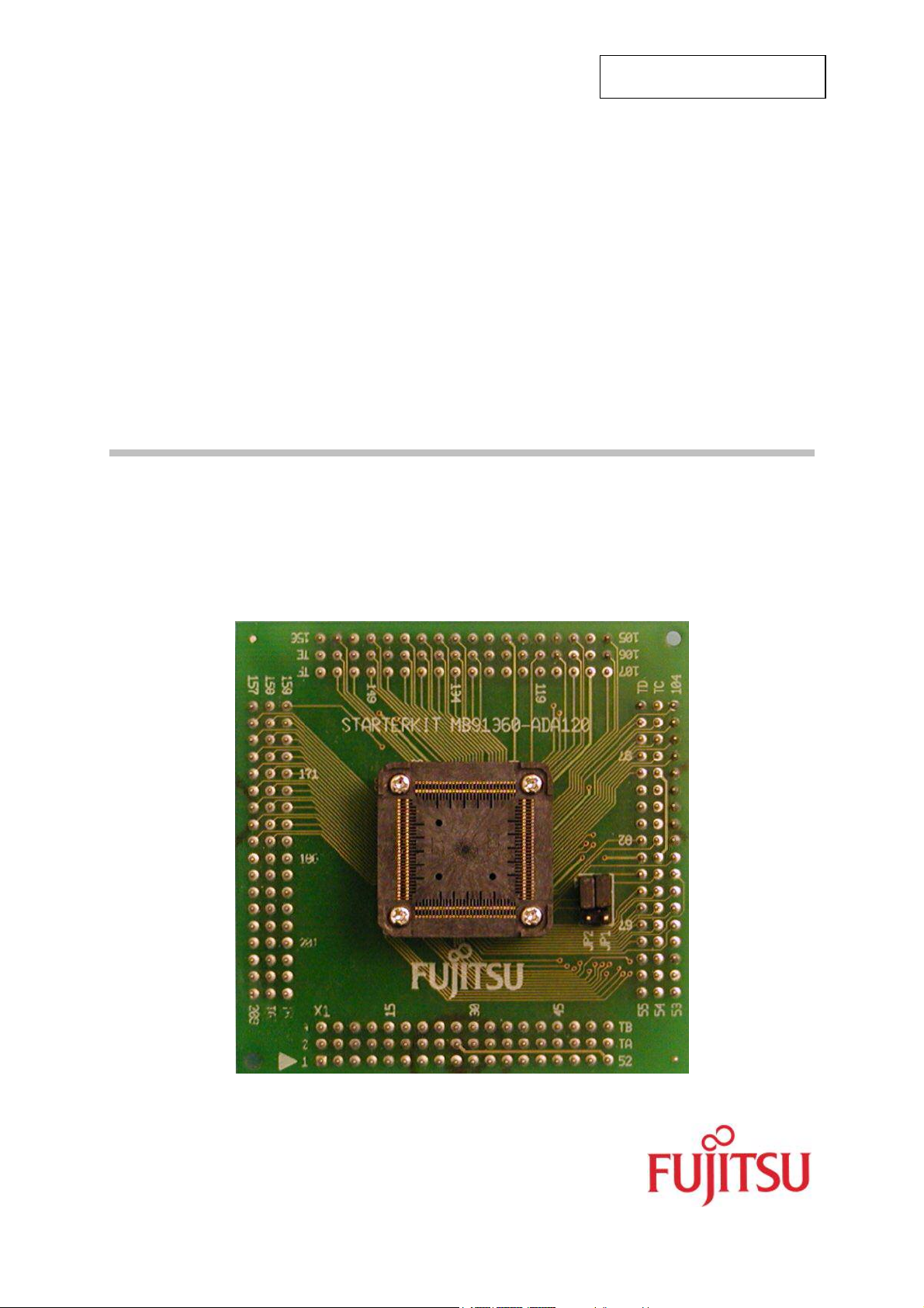
STARTERKIT ADAPTER
STARTERKITMB91360-ADA120
FMEMCU- UG-910002-15
MB91360 SERIES
USER GUIDE
Page 2
STARTERKITMB91360-ADA120
Revision History
Revision History
Date Issue
02.07.01 Ver. 1.0
First draft
10.07.01 Version 1.1
File compression settings changed
17.07.01 Version 1.2
Corrections
31.10.02 Version 1.3, MST
New format, MB91F365G/F366G series added
22/01/2003 Version 1.4
Typos corrected
06/02/2003 Version 1.5, MST
Typos corrected
This document contains 17 pages.
UG-910002-15 - 2 - © Fujitsu Microelectronics Europe GmbH
Page 3

STARTERKITMB91360-ADA120
Warranty and Disclaimer
Warranty and Disclaimer
To the maximum extent permitted by applicable law, Fujitsu Microelectronics Europe GmbH restricts
its warranties and its liability for STARTERKITMB91360-ADA120 and all its deliverables (eg.
software include or header files, application examples, target boards, evaluation boards, engineering
samples of IC’s etc.), its performance and any consequential damages, on the use of the Product in
accordance with (i) the terms of the License Agreement and the Sale and Purchase Agreement under
which agreements the Product has been delivered, (ii) the technical descriptions and (iii) all
accompanying written materials. In addition, to the maximum extent permitted by applicable law,
ujitsu Microelectronics Europe GmbH disclaims all warranties and liabilities for the performance of
F
the Product and any consequential damages in cases of unauthorised decompiling and/or reverse
engineering and/or disassembling. Note, the STARTERKITMB91360-ADA120 and all its
deliverables are intended and must only be used in an evaluation laboratory environment.
1. Fujitsu Microelectronics Europe GmbH warrants that the Product will perform substantially in
accordance with the accompanying written materials for a period of 90 days form the date of
receipt by the customer. Concerning the hardware components of the Product, Fujitsu
Microelectronics Europe GmbH warrants that the Product will be free from defects in material
and workmanship under use and service as specified in the accompanying written materials
for a duration of 1 year from the date of receipt by the customer.
2. Should a Product turn out to be defect, Fujitsu Microelectronics Europe GmbH´s entire liability
and the customer´s exclusive remedy shall be, at Fujitsu Microelectronics Europe GmbH´s
sole discretion, either return of the purchase price and the license fee, or replacement of the
Product or parts thereof, if the Product is returned to Fujitsu Microelectronics Europe GmbH in
original packing and without further defects resulting from the customer´s use or the transport.
However, this warranty is excluded if the defect has resulted from an accident not attributable
to Fujitsu Microelectronics Europe GmbH, or abuse or misapplication attributable to the
customer or any other third party not relating to Fujitsu Microelectronics Europe GmbH.
3. To the maximum extent permitted by applicable law Fujitsu Microelectronics Europe GmbH
disclaims all other warranties, whether expressed or implied, in particular, but not limited to,
warranties of merchantability and fitness for a particular purpose for which the Product is not
designated.
4. To the maximum extent permitted by applicable law, Fujitsu Microelectronics Europe GmbH´s
and its suppliers´ liability is restricted to intention and gross negligence.
NO LIABILITY FOR CONSEQUENTIAL DAMAGES
To the maximum extent permitted by applicable law, in no event shall Fujitsu
Microelectronics Europe GmbH and its suppliers be liable for any damages whatsoever
(including but without limitation, consequential and/or indirect damages for personal
injury, assets of substantial value, loss of profits, interruption of business operation,
loss of information, or any other monetary or pecuniary loss) arising from the use of
the Product.
Should one of the above stipulations be or become invalid and/or unenforceable, the remaining
stipulations shall stay in full effect
© Fujitsu Microelectronics Europe GmbH - 3 - UG-910002-15
Page 4

STARTERKITMB91360-ADA120
Contents
Contents
REVISION HISTORY............................................................................................................ 2
WARRANTY AND DISCLAIMER ......................................................................................... 3
CONTENTS .......................................................................................................................... 4
0 INTRODUCTION.............................................................................................................. 5
1 INTERFACING THE MB91360 STARTER KIT TO THE STARTERKITMB91360-ADA120
AND PROBE CABLE....................................................................................................... 6
2 APPENDIX....................................................................................................................... 8
2.1 Pin comparision....................................................................................................... 8
2.2 Figures.................................................................................................................. 15
3 RELATED PRODUCTS ................................................................................................. 16
4 INFORMATION IN THE WWW....................................................................................... 17
UG-910002-15 - 4 - © Fujitsu Microelectronics Europe GmbH
Page 5

STARTERKITMB91360-ADA120
Introduction
0 Introduction
The Starterkit91360 is the Evaluation board for MB91360G series.
It is equipped with MB91F362G series (208-pin).
When using a 120-pin derivate (MB91F365G/F366G/F367G/F368G) the adapter board
STARTERKITMB91360-ADA120 is mapping the pins to the functions on the Starterkit91360.
© Fujitsu Microelectronics Europe GmbH - 5 - UG-910002-15
Page 6
STARTERKITMB91360-ADA120
Chapter 1 Interfacing the MB91360 Starter Kit to the STARTERKITMB91360-ADA120 and probe Cable
1 Interfacing the MB91360 Starter Kit to the
STARTERKITMB91360-ADA120 and probe Cable
The MB91F367/8 is a 120-pin derivative of the MB91360 family processors. The
MB91F367/8 is packaged in the FTP-120P-M21.
In order to allow users to develop applications on the MB91360 Starter Kit, an adaptor board
and Probe Cable have been developed.
The Adapter Board (STARTERKITMB91360-ADA120), which converts the MB91F362 in out
to the MB91F365/6/7/8 pin out, can be fitted to the Starter Kit with the use of Pin Headers.
For the Adapter board to be fitted correctly, the MB91F362 MCU and socket cap must be
removed from the Starter kit.
The Adapter Board is fitted with an NQPACK120SD enabling the user to fit either an MCU or
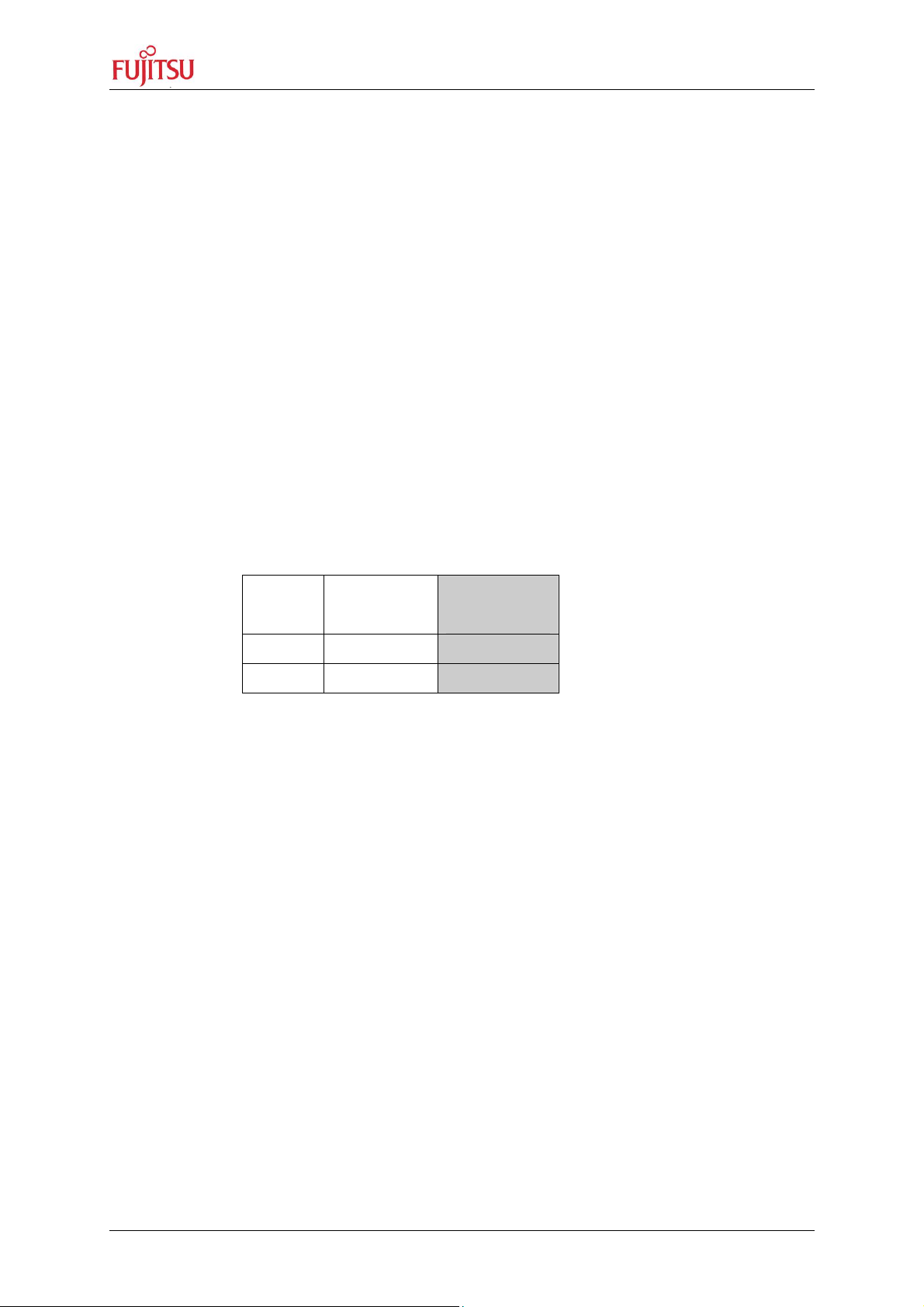
the Probe Cable. Jumpers J1 and J2 enable switching between sub clock and D/A Converter
on pins 27 and 28 – please see circuit diagram for details.
Jumper MB91F365G
MB91F367G
JP1 1-2 2-3
JP2 1-2 2-3
Note: Default Jumper Setting: MB91F368G JP1, JP2 = 2-3
The Probe cable interfaces between the Emulator MB2197-01 and the NQPACK120SD.
Please note the direction of the probe cable when fitted onto the Starter Kit. The probe cable
is offset by 90° compared to the MB91FV360G.
Also included is a pin cross-reference between the MB91FV360, MB91F365/6 and
MB91F367/8.
The following diagram shows the starter kit assembled with the STARTERKITMB91360ADA120 Adapter board and probe cable.
MB91F366G
MB91F368G
UG-910002-15 - 6 - © Fujitsu Microelectronics Europe GmbH
Page 7

STARTERKITMB91360-ADA120
Chapter 1 Interfacing the MB91360 Starter Kit to the STARTERKITMB91360-ADA120 and probe Cable
Figure 1 Diagram showing how to connect the STARTERKITMB91360-ADA120
Adapter board and Probe Cable to the MB91360 Starter Kit
© Fujitsu Microelectronics Europe GmbH - 7 - UG-910002-15
Page 8

2 Appendix
rter
2.1 Pin comparision
STARTERKITMB91360-ADA120
Chapter 2 Appendix
Pin Function
VDD 25 1 1
VSS 26 2 2
LED4 PJ4 88 3 3 LED
LED5 PJ5 89 4 4 LED
LED6 PJ6 90 5 5 LED
LED7 PJ7 91 6 6 LED
ATGX PI3 80 7 7 JP16
VDD 51 8 8
VSS 52 9 9
SGO PM0 126 10 10 JP16
SGA PM1 127 11 11 JP16
SDA PM2 128 12 12 JP20
SCL PM3 129 13 13 JP20
VDD 79 14 14
Port Function
Where specified)
(
MB91F362
Pin
Number
MB90F365/
F366 Pin
Number
MB90367/
F368 Pin
Number
MB91360 Sta
Kit Pin
Allocation
VSS 78 15 15
AVRH 65 16 16
AVCC 64 17 17
AVSS 74 18 18 JP16
AN0 PH0 66 19 19 JP16
AN1 PH1 67 20 20 JP16
AN2 PH2 68 21 21 JP16
AN3 PH3 69 22 22 JP16
AN4 PH4 70 23 23 JP16
AN5 PH5 71 24 24 JP16
AN6 PH6 72 25 25 JP16
AN7 PH7 73 26 26 JP16
DA0: (MB91F365G) 75
X0A: (MB91F366G) 121
N .C. (MB91F367G)
X0A: (MB91F368G) 121
DA1: (MB91F365G) 76
X1A: (MB91F366G) 122
27
JP16
27
JP16
28
UG-910002-15 - 8 - © Fujitsu Microelectronics Europe GmbH
Page 9

STARTERKITMB91360-ADA120
rter
Chapter 2 Appendix
Pin Function
N.C.: (MB91F367G)
Port Function
(Where specified)
MB91F362
Pin
Number
MB90F365/
F366 Pin
Number
MB90367/
F368 Pin
Number
MB91360 Sta
Kit Pin
Allocation
28
X1A: (MB91F368G) 122
ALARM 77 29 29
VSS 93 30 30
AH/BOOT P93 46 31 31 SW1
TESTX 81 32 32
CPUTESTX 82 33 33
VDD 92 34 34
X0 119 35 35
X1 120 36 36
VSS 110 37 37
MONCLK 116 38 38
INT0 PK0 94 39 39 JP20
INT1 PK1 95 40 40 JP20
INT2 PK2 96 41 41 JP20
INT3 PK3 97 42 42 JP20
INT4 PK4 98 43 43 JP20
INT5 PK5 99 44 44 JP20
INT6 PK6 100 45 45 JP20
INT7 PK7 101 46 46 JP20
VDD 144 47 47
VCC3/C 159 48 48
VSS 123 49 49
IN0 PL0 102 50 50 JP20
IN1 PL1 103 51 51 JP20
IN2 PL2 104 52 52 JP20
IN3 PL3 105 53 53 JP20
OUT0 PL4 106 54 54 JP20
OUT1 PL5 107 55 55 JP20
VDD 160 56 56
MD0 111 57 57 SW1
MD1 112 58 58 SW1
MD2 113 59 59 SW1
INITX 115 60 60 JP25
VDD 182 61 61
VSS 145 62 62
© Fujitsu Microelectronics Europe GmbH - 9 - UG-910002-15
Page 10

STARTERKITMB91360-ADA120
rter
Chapter 2 Appendix
Pin Function
Port Function
(Where specified)
MB91F362
Pin
Number
MB90F365/
F366 Pin
Number
MB90367/
F368 Pin
Number
MB91360 Sta
Kit Pin
Allocation
SOT4 PN0 130 63 63 JP14
SIN4 PN1 131 64 64 JP14
SCK4 PN2 132 65 65 JP14
SIN3 PN3 133 66 66 JP14
SOT3 PN4 134 67 67 JP14
SCK3 PN5 135 68 68 JP14
VSS 158 69 69
OCPA0 PO0 136 70 70 JP15
OCPA1 PO1 137 71 71 JP15
OCPA2 PO2 138 72 72 JP15
OCPA3 PO3 139 73 73 JP15
OCPA4 PO4 74
PO4 PO4
143
74
JP15
OCPA5 PO5 75
PO5 PO5
141
75
JP15
OCPA6 PO6 76
PO6 PO6
142
76
JP15
OCPA7 PO7 77
PO7 PO7
143
77
JP15
TX0 PP0 146 78 78 JP14
RX0 PP1 147 79 79 JP14
TX1 PP2 148 80 80 JP14
RX1 PP3 149 81 81 JP14
VDD 108 82 82
VSS 83 83
SIN0 PQ0 152 84 84 JP14
SOT0 PQ1 153 85 85 JP14
SIN1 PQ2 86
PQ2 PQ2
154
86
JP14
SOT1 PQ3 87
PQ3 PQ3
155
87
JP14
AN8 PG0 53 88 88 LCD
AN9 PG1 54 89 89 LCD
AN10 PG2 55 90 90 LCD
AN11 PG3 56 91 91 LCD
AN12 PG4 57 92 92 LCD
UG-910002-15 - 10 - © Fujitsu Microelectronics Europe GmbH
Page 11

STARTERKITMB91360-ADA120
rter
Chapter 2 Appendix
Pin Function
Port Function
(Where specified)
MB91F362
Pin
Number
MB90F365/
F366 Pin
Number
MB90367/
F368 Pin
Number
MB91360 Sta
Kit Pin
Allocation
AN13 PG5 58 93 93 LCD
VDD 94 94
HVSS 171 95
VSS 171 95
PWM1P0 PR0 96
PR0 PR0
162
96
JP15
PWM1M0 PR1 97
PR1 PR1
163
97
JP15
PWM2P0 PR2 98
PR2 PR2
164
98
JP15
PWM2M0 PR3 99
PR3 PR3
165
99
JP15
HVDD 166 100 100
PWM1P1 PR4 101
PR4 PR4
167
101
JP15
PWM1M1 PR5 102
PR5 PR5
168
102
JP15
PWM2P1 PR6 103
PR6 PR6
169
103
JP15
PWM2M1 PR7 104
PR7 PR7
170
104
JP15
HVSS 161 105 105
PWM1P2 PS0 106
PS0 PS0
172
106
JP15
PWM1M2 PS1 107
PS1 PS1
173
107
JP15
PWM2P2 PS2 108
PS2 PS2
174
108
JP15
PWM2M2 PS3 109
PS3 PS3
175
109
JP15
HVDD 176 110 110
PWM1P3 PS4 111
PS4 PS4
177
111
JP15
PWM1M3 PS5 112
PS5 PS5
178
112
JP15
PWM2P3 PS6 179 113 JP15
© Fujitsu Microelectronics Europe GmbH - 11 - UG-910002-15
Page 12

STARTERKITMB91360-ADA120
rter
Chapter 2 Appendix
Pin Function
Port Function
(Where specified)
MB91F362
Pin
Number
MB90F365/
F366 Pin
Number
MB90367/
F368 Pin
Number
MB91360 Sta
Kit Pin
Allocation
PS6 PS6 113
PWM2M3 PS7 114
PS7 PS7
180
114
JP15
HVSS 181 115 115
VDD 116 116
LED0 PJ0 84 117 117 LED
LED1 PJ1 85 118 118 LED
LED2 PJ2 86 119 119 LED
LED3 PJ3 87 120 120 LED
A0 9 JP25
A1 10 JP25
A10 19 JP25
A11 20 JP25
A12 21 JP25
A13 22 JP25
A14 23 JP25
A15 24 JP25
A16 27 JP25
A17 28 JP25
A18 29 JP25
A19 30 JP25
A2 11 JP25
A20 31 JP25
A3 12 JP25
A4 13 JP25
A5 14 JP25
A6 15 JP25
A7 16 JP25
A8 17 JP25
A9 18 JP25
ALE P91 44 JP25
AN14 PG6 59 LCD
AN15 PG7 60 LCD
AS P90 43 JP25
BGRNTX 36 JP25
BRQ 37 JP25
UG-910002-15 - 12 - © Fujitsu Microelectronics Europe GmbH
Page 13

STARTERKITMB91360-ADA120
rter
Chapter 2 Appendix
Pin Function
Port Function
(Where specified)
MB91F362
Pin
Number
MB90F365/
F366 Pin
Number
MB90367/
F368 Pin
Number
MB91360 Sta
Kit Pin
Allocation
CLK 45 JP25
CP0 124
CS0X P94 47 JP25
CS1X P95 48 JP25
CS2X P96 49 JP25
CS3X P97 50 JP25
CS4X 32 JP25
CS5X 33 JP25
CS6X 34 JP25
D0 183 JP24
D1 184 JP24
D10 193 JP24
D11 194 JP24
D12 195 JP24
D13 196 JP24
D14 107 JP24
D15 200 JP24
D16 201 JP24
D17 202 JP24
D18 203 JP24
D19 204 JP24
D2 185 JP24
D20 205 JP24
D21 206 JP24
D22 207 JP24
D23 208 JP24
D24 1 JP24
D25 2 JP24
D26 3 JP24
D27 4 JP24
D28 5 JP24
D29 6 JP24
D3 186 JP24
D30 7 JP24
D31 8 JP24
D4 187 JP24
© Fujitsu Microelectronics Europe GmbH - 13 - UG-910002-15
Page 14

STARTERKITMB91360-ADA120
rter
Chapter 2 Appendix
Pin Function
Port Function
(Where specified)
MB91F362
Pin
Number
MB90F365/
F366 Pin
Number
MB90367/
F368 Pin
Number
MB91360 Sta
Kit Pin
Allocation
D5 188 JP24
D6 189 JP24
D7 190 JP24
D8 191 JP24
D9 192 JP24
DACK0 PB1 62 JP25
DEOP0 PB2 63 JP25
DREQ PB0 61 JP25
HSTX 114
LTESTX 83
OUT2 PL6 108 JP20
OUT3 PL7 109 JP20
RDX 38 JP25
RDY 35 JP25
RX2 PP5 151 JP14
SELCLK 117
SIN2 PQ4 156 JP14
SOT2 PQ5 157 JP14
TX2 PP4 150 JP14
VCI 125
VDD35
VDD35
VDD35
VDD35
VDD35
VDD35
VDD35
VDDI
VDDI
VDDI
VDDI
VDDX 118
VSS 199
VSS
VSS
VSS
UG-910002-15 - 14 - © Fujitsu Microelectronics Europe GmbH
Page 15

STARTERKITMB91360-ADA120
rter
Chapter 2 Appendix
Pin Function
VSS
WR0X 39 JP25
WR1X 43 JP25
WR2X 41 JP25
WR3X 42 JP25
Port Function
(Where specified)
MB91F362
Pin
Number
MB90F365/
F366 Pin
Number
MB90367/
F368 Pin
Number
MB91360 Sta
Kit Pin
Allocation
Figure 2: Table comparing Pin and functions for the MB91FV360 series, MB91F369
and MB91F367/8
NOTE:
N.C. : Not connected
2.2 Figures
Figure 1 Diagram showing how to connect the MB91F367/8 Adapter board and Probe
Cable to the MB90F360 Starter Kit........................................................................... 7
Figure 2: Table comparing Pin and functions for the MB91FV360 series, MB91F369 and
MB91F367/8............................................................................................................. 8
© Fujitsu Microelectronics Europe GmbH - 15 - UG-910002-15
Page 16

STARTERKITMB91360-ADA120
Chapter 3 Related Products
3 Related Products
< Starterkit91360 Evaluation board for MB91360 series
< MB2197-01 Emulator debugger main unit
< MB2197-10 DSU Probe Cable
< MB2197-120 Adapter board for MB91FV360G Evaluation device
< MB2197-127 Probe cable for 208-pin socket (MB91F362G)
< FR360-PROBE-120 Probe Cable for 120 pin devices
(MB91F365G/366G/367G/368G/376G)
< FR360-PROBE-160 Probe Cable for 160 pin devices (MB91F369G)
< NQPACK120SD Socket for package FPT-120P-M21
(Tokyo Eletech Corp. www.tetc.co.jp/e_tet.htm
)
< HQPACK120Sd Header for NQPACK120SD
UG-910002-15 - 16 - © Fujitsu Microelectronics Europe GmbH
Page 17

STARTERKITMB91360-ADA120
Chapter 4 Information in the WWW
4 Information in the WWW
Information about FUJITSU MICROELECTRONICS Products
can be found on the following Internet pages:
Microcontrollers (8-, 16- and 32bit), Graphics Controllers
Datasheets and Hardware Manuals, Support Tools (Hard- and Software)
http://www.fme.gsdc.de/gsdc.htm
Memory products: Flash, SDRAM and FRAM
http://www.fme.fujitsu.com/products/memory/index1.html
Linear Products: Power Management, A/D and D/A Converters
http://www.fme.fujitsu.com/products/linear/start.html
Media Products: SAW filters, acoustic resonators and VCOs
http://www.fme.fujitsu.com/products/media/index1.html
For more information about FUJITUS MICROELECTRONICS
http://www.fme.fujitsu.com/products/start.html
© Fujitsu Microelectronics Europe GmbH - 17 - UG-910002-15
 Loading...