

Page 1
Copyright
Copyright
Fujitsu has made every effort to ensure the
accuracy and completeness of this document.
Because ongoing development efforts are
made to continually improve the capabilities of
our products, however, the data contained
herein represents Fujitsu design objectives and
is provided for comparative purposes; actual
results may vary based on a variety of f actors .
This product data does not constitute a
warranty. Specifications are subject to change
without knowledge.
Fujitsu and the Fujitsu logo are registered
trademarks of Fujitsu Limited; Stylistic is a
registered trademark of Fujitsu.
Microsoft and Windows are registered
trademarks of Microsoft Corporation.
DECLARATION OF CONFORMITY
PCMCIA and CardBus are registered
trademarks of the Personal Computer Memory
Card International Association.
Intel, Pentium, and SpeedStep are registered
trademarks of Intel Corporation.
Wi-Fi is a trademark of the Wireless Ethernet
Compatibility Alliance (WECA).
All other products are trademarks or registered
trademarks of their respective companies.
Copyright 2003 - Fujitsu. All rights reserved.
No part of this publication may be copied,
reproduced, or translated, without the prior
written consent of Fujitsu. No part of this
publication may be stored or transmitted in an y
electronic form without the prior consent of
Fujitsu.
according to FCC Part 15
This device complies with Part 15 of the FCC rules. Operation is subject to the following two
conditions:
(1) This device ma y not cause harmful interference, and, (2) This device must accept any
interference received, including interference that may cause undesired operation.
i
Page 2

Fujitsu Stylistic ST4120P/21P Tablet PC - User’s Guide
ii
Page 3

Table of Contents
Table of Content
PREFACE
About This Guide
1
GETTING STARTED
WITH Y OUR FUJITSU
STYLISTIC ST4120P/21P
TABLET PC
Getting Started with Your Fujitsu Stylistic
ST4120P/21P T ab let PC ...........................3
Fujitsu Stylistic ST4210P/21P Tablet PC
Features....................................................4
Status Display ................................................9
Application Buttons ........................................11
Navigation Buttons .........................................13
Tertiary Functions Of Application
and Navigation Buttons.............................14
Connectors And Peripheral Interfaces ...........15
2
USING Y OUR FUJITSU
STYLISTIC ST4120P/21P
3
CARE AND MAINTENANCE
Care and Maintenance................................... 31
Protecting the Display Screen........................31
Storing the Tablet PC .....................................32
Avoiding Overheating .....................................32
Cleaning the Display Screen..........................32
Troubleshooting ..............................................32
4
SPECIFICATIONS
Fujitsu Stylistic ST4120P/21P Hardware
Specifications............................................37
Physical Specifications...................................37
Processing Specifications ..............................37
Memory/Storage Specifications .....................37
Display Specifications ....................................37
Interface Specifications ..................................37
Power Specifications ......................................38
Environmental Specifications .........................38
Agency Approval Specifications..................... 38
Additional Specifications ................................38
TABLET PC
Using the Fujitsu Stylistic ST4120P/21P
Tablet PC ..................................................19
System States ................................................19
Powering Up the Pen Table PC ......................20
Shutting Down the System.............................20
Suspending System Operation ......................20
Resuming System Operation .........................22
Using the Pen.................................................22
Installing a Pen Tether ....................................23
Calibrating the Pen.........................................23
Using Hovering Mode.....................................24
Charging the Battery ......................................24
Removing and Installing
the Battery ................................................25
Tips for Conserving Battery Power ................25
Modem Connection ........................................26
PC Card Slot ..................................................26
Removing and Installing
Memory Modules ......................................26
5
AGENCY NOTICES
Regulatory Information................................... 41
Notice .............................................................41
APPENDIX
Wireless LAN User’s Guide
FCC Regulatory Information ..........................47
Before Using This Device...............................49
Connecting Windows 2000 Systems..............50
Network Connection: Windows 2000 .............53
Connecting Windows XP Systems................. 57
Troubleshooting ..............................................61
About IP Addresses .......................................66
Specifications .................................................67
iii
Page 4

Fujitsu Stylistic ST4120P/21P Tablet PC - User’s Guide
iv
Page 5

Preface
v
Page 6

Fujitsu Stylistic ST4120P/21P Tablet PC - User’s Guide
vi
Page 7
Preface
ABOUT THIS GUIDE
The Fujitsu Stylistic® ST4120P/21P Tablet PC
is a high performance, pen-based computer
that has been designed to support Microsoft
Windows® 2000 or Windows XP Professional.
This manual explains how to operate your
Fujitsu Stylistic ST4120P/21P Tablet PC’s
hardware and built-in system software.
Preface
®
The point icon highlights information that
will enhance your understanding of the
subject material.
The Fujitsu Stylistic ST4120P/21P Tablet PC is
a completely self-contained unit with a activematrix (TFT) color LCD display and an passive
Touch Panel. It has a powerful interface that
enables it to support a variety of optional
features.
Conventions Used in the Guide
Keyboard keys appear in brackets.
Example: [Fn], [F1], [ESC], [ENTER] and
[CTRL].
Pages with additional information about a
specific topic are cross-referenced within the
text.
Example: (See page xx.)
On screen buttons or menu items appear in
bold
Example: Click OK to restart your Tablet PC.
DOS commands you enter appear in Courier
type.
Example: Shut down the computer?
The caution icon highlights information that
is important to the safe operation of your
computer, or to the integrity of y our files .
Please read all caution information
carefully.
The warning icon highlights information
that can be hazardous to either you, your
Fujitsu Stylistic ST4120P/21P Tablet PC or
your files. Please read all warning
information carefully.
vii
vii
Page 8

Fujitsu Stylistic ST4120P/21P Tablet PC - User’s Guide
IMPORTANT SAFETY INSTRUCTIONS
1. Read these instructions carefully. Save these instructions for future reference.
2. Follow all warnings and instructions marked on the product.
3. Unplug this product from the wall outlet before cleaning. Do not use liquid cleaners or aerosol cleaners .
Use a damp cloth for cleaning.
4. Do not use this product near water.
5. Do not place this product on an unstable cart, stand, or table. The product may fall, causing serious
damage to the product.
6. Slots and openings in the cabinet and the back or bottom are provided f or ventilation; to ensure reliab le
operation of the product and to protect it from overheating, these openings must not be blocked or
covered. The openings should never be blocked by placing the product on a bed, sofa, rug, or other
similar surface. This product should ne ver be placed near or over a r adiator or heat register, or in a b uiltin installation unless proper ventilation is provided.
7. This product should be operated from the type of power indicated on the marking label. If you are not
sure of the type of power available, consult your dealer or local power company.
8. This product is equipped with a 3-wire grounding-type plug, a plug having a third (grounding) pin. This
will only plug into a grounding-type power outlet. This is a saf ety feature. If you are unable to insert the
plug into the outlet, contact your electrician to replace your obsolete outlet. Do not defeat the purpose
of the grounding-type plug.
9. Do not allow anything to rest on the power cord. Do not locate this product where persons will walk on
the cord.
10. If an extension cord is used with this product, make sure that the total ampere rating of the equipment
plugged into the extension cord does not exceed the extension cord ampere rating. Also, make sure
that the total rating of all products plugged into the wall outlet does not exceed 15 amperes.
11. Never push objects of any kind into this product through cabinet slots as they may touch dangerous
voltage points that could result in a fire or electric shock. Never spill liquid of any kind on the product.
12. Do not attempt to service this product yourself, as opening or removing covers may expose you to
dangerous voltage points or other risks. Refer all servicing to qualified service personnel.
13. Unplug this product from the wall outlet and refer servicing to qualified service personnel under the
following conditions:
a. When the power cord or plug is damaged or frayed.
b. If liquid has been spilled into the product.
c. If the product has been exposed to rain or water.
d. If the product does not operate normally when the operating instructions are followed. Adjust
only those controls that are covered by the operating instructions since improper adjustment of
other controls may result in damage and will often require extensive work by a qualified tech-
nician to restore the product to normal condition.
e. If the product has been dropped or the cabinet has been damaged.
f. If the product exhibits a distinct change in performance, indicating a need for service.
14. CAUTION. When replacing the battery, be sure to install it with the polarities in the correct posi-
tion. There is a danger of explosion if the battery is replaced with an incorrect type or is mistreated. Do not rechar ge, disassemble or dispose of in fire. Replace onl y with the same or equivalent type recommeded by the manufacturer . Dispose of the used battery according to the manufacturer’s instructions.
15. Use only the proper type of power supply cord set (provided in your accessories box) for this unit. It
should be a detachable type: UL listed/CSA certified, BS1363,ASTA,SS145 cer tified, rated 10A 250V
minimum, VDE approved or its equivalent. Maximum length is 15 feet (4.6 meters).
viii
Page 9

Preface
HIGH SAFETY REQUIRED USE
This Product is designed, developed and man ufactured as contemplated for general use, including without
limitation, general office use, personal use, household use and ordinary industrial use, but is not
designed,developed and manufactured as contemplated for use accompanying fatal risks or dangers that,
unless extremely high safety is secured, could lead directly to death, personal injury,severe physical damage or other loss (hereinafter ‘High Safety Required Use’), including without limitation, nuclear power
reactioncore control in nuclear atomic facility, air plane automatic aircraft flight control, air traffic control,
operation control in mass transport control system,medical instrument for life support system, missile launching control in weapon system. You shall not use this Product without securing the sufficient safety required
for the High Safety Required Use.
ix
ix
Page 10

Fujitsu Stylistic ST4120P/21P Tablet PC - User’s Guide
DATA STORAGE MEDIA AND CUSTOMER RESPONSIBILITIES
The only effective protection for the data stored in a computer,such as on a hard disk,is f or y ou, Purchaser
to regularly back up the data.Fujitsu and its affiliates,suppliers,service providers and resellers shall not be
responsible for an y software programs ,data or other information stored or used on any media or part of any
Product returned to Fujitsu or its service providers for Warranty Service or other repair,including but not
limited to the costs of recovering such programs,data or other information.It is solely your responsibility as
the Purchaser to back up any software programs, data,or information stored on any storage media or any
part of a Product returned for Warranty Service or repair to the designated service centers.
x
Page 11

1
Getting Started
with Your Fujitsu
Stylistic ST4120P/21P
Tablet PC
1
Page 12

Fujitsu Stylistic ST4120P/21P Tablet PC User’s Guide - Section One
2
Page 13

Getting Started
Getting Started with Your Fujitsu Stylistic
ST4120P/21P T ablet PC
Figure 1-1 Fujitsu Stylistic ST4120P/21P Tablet PC
Fujitsu Stylistic® ST4120P/21P Tablet PC is a
high performance, pen-based computer that
has been designed to support Microsoft
Windows® 2000 or Windows XP Professional.
This chapter provides an overview of the
Fujitsu Stylistic ST4120P/21P Tablet PC and its
features.
®
3
Page 14
Fujitsu Stylistic ST4120P/21P Tablet PC User’s Guide - Section One
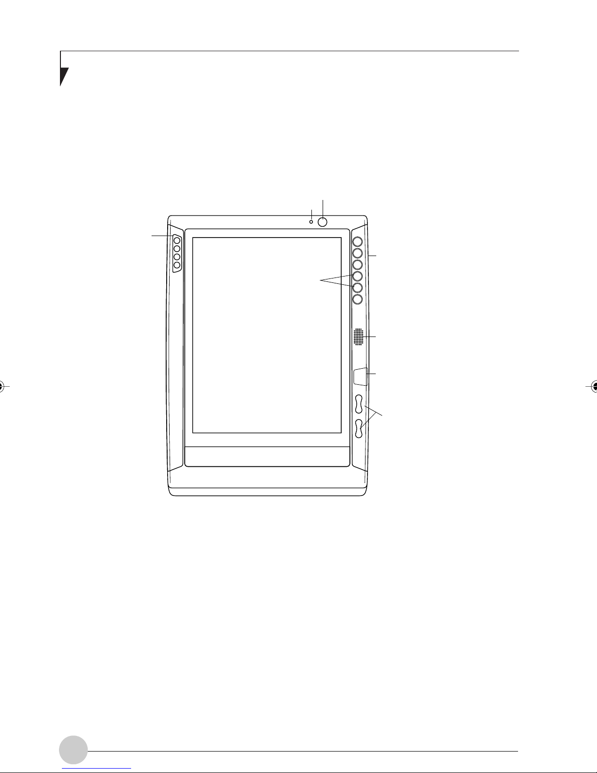
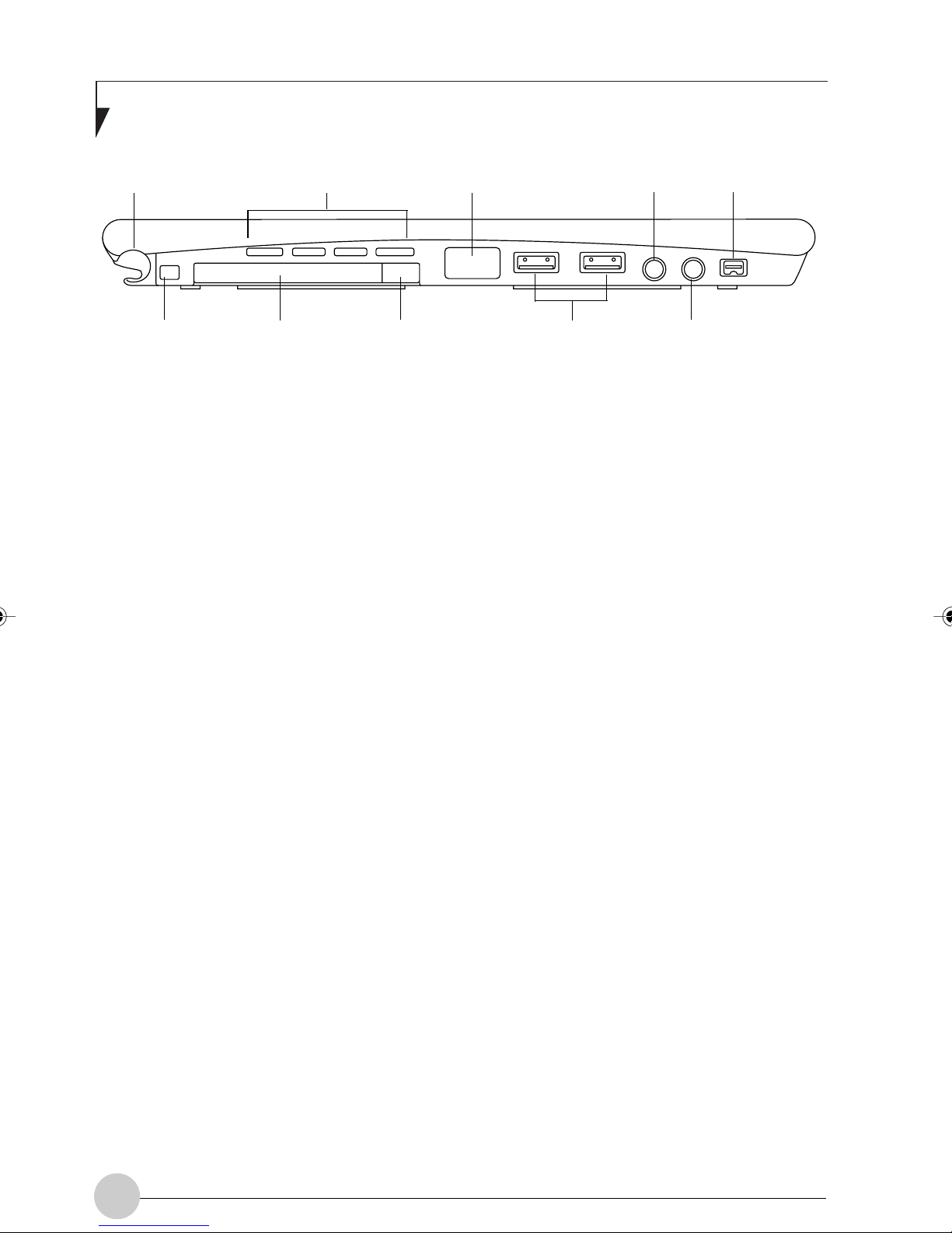
FUJITSU STYLISTIC ST4120P/21P TABLET PC FEATURES
Features and controls that you use to operate the Fujitsu Stylistic ST4120P/21P T ablet PC are
outlined below and illustrated in Figures 1-1 through 1-5. Details on using these features and
controls are provided later in this manual.
Power On/Suspend/
Resume Button
Built-in Microphone
System
Status
LEDs
User-Programmable
Application Buttons
Application
Buttons
Speaker
Figure 1-2 Fujitsu Stylistic ST4120P/21P Tablet PC Features (Front View)
Front Features:
• System status LEDs: Indicate the
operational status of the Pen Tablet PC and
hard disk drive, the charge level of the
battery, and the status of the hovering mode.
• Po wer On/Suspend/Resume button:
Allows you to turn on, off, suspend, resume,
hibernate or wake the Pen Tablet PC in order
to optimize battery life.
Infrared
Keyboard/
Mouse Port
Navigation
Buttons
• Application buttons: Allow you to quickly
launch pre-defined applications and utilities
by pressing a button.
• Navigation buttons: The navigation buttons
allow you to move: Page Up/Page Down,
Tab Right/Tab Left, Cursor Up/Cursor Down,
and Cursor Right/ Cursor Left.
• Speaker: Allows you to listen to mono audio
files.
• Infrared keyboard/mouse port: The
infrared port wraps around the front and
bottom of the display, and is used for
communicating with a proprietary infrared
keyboard or mouse .❖
4
• Built-in Microphone: The built-in
microphone allows you to input mono audio.
❖ These peripherals and accessories are sold
separately.
Page 15
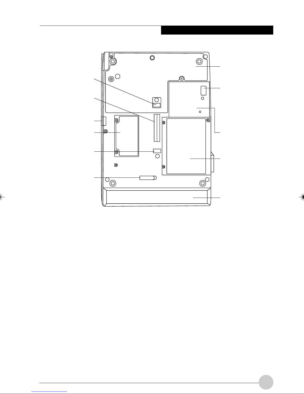
Table Dock
Latch Point
System
Interface
Connector
Latch Point
Getting Started
Thermal suede
Wireless
LAN On/OFF
Switch
Memory
Module
Cover
Tablet Dock
Latch Point
Battery
Release
Latch
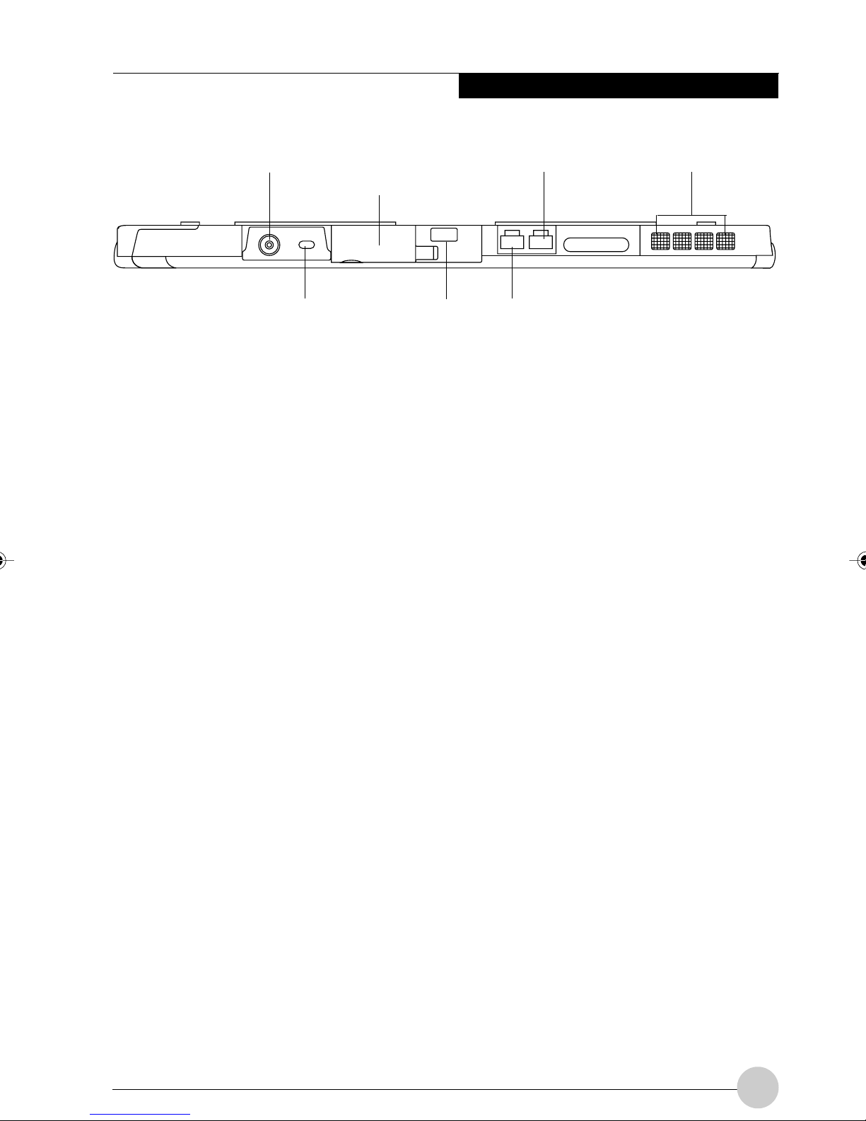
Figure 1-3 Fujitsu Stylistic ST4120P/21P Tablet PC Features (Back View)
Back Features:
• System interface connector: Allows you to
connect the optional Stylistic Tablet Dock.❖
• Removable battery: Can be removed and
replaced with a charged battery.❖
• Battery release latch: Used to release the
removable battery.
• Tablet Dock latch point: Allows you to
attach the system to an optional Tablet
Dock.❖
• Memory module cover: Removab le co ver
over the memory modules.
• Thermal Suede: Several areas of the
system back are covered with “thermal
suede”. This material should not be
removed. It is designed to minimize the
temperature of the system for the user when
a running system is carried for a period of
time.
Wireless LAN
and Modem
Module Cover
HardDisk
Drive Cover
Removeable
Battery
• Wireless LAN module cover: Provides
protection for wireless LAN radio solution.
• Wireless LAN On/Off switch: This switch
turns the device on and off. You should
switch the device off when it is not in use in
order to maximize battery life.
• Hard disk drive cover: Covers the hard disk
drive module.
❖ These peripherals and accessories are sold
separately.
5
Page 16
Fujitsu Stylistic ST4120P/21P Tablet PC User’s Guide - Section One
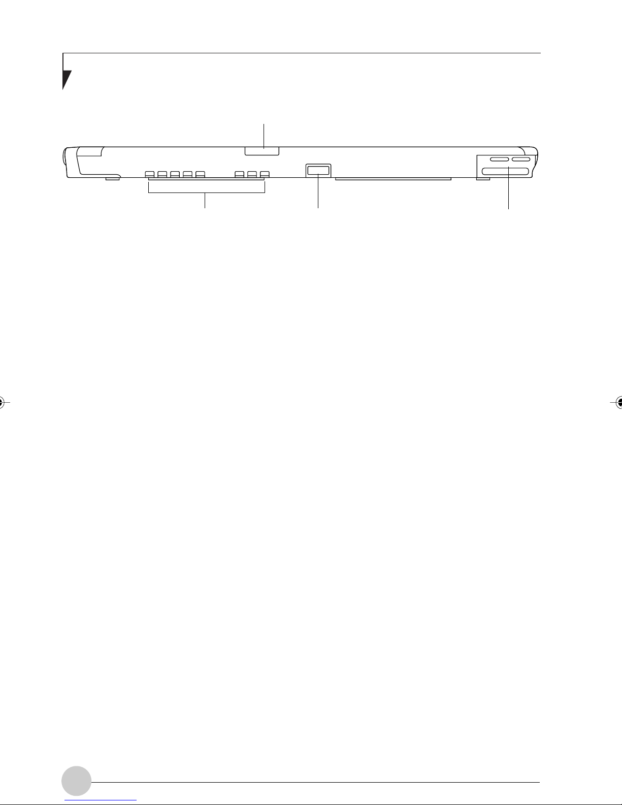
Pen Holder Air flow vents IrDA Port
Pen Tether
Attachment Point
PC Card Slot
PC Card
Eject Button
Figure 1-4 Fujitsu Stylistic ST4120P/21P Tablet PC Features (Top View)
T op Features:
• Pen: The main input device that you use to
execute programs and enter data. A pen
holder is built into the Pen Tablet PC to store
the pen when not in use.
• Microphone Jack: Allo ws y ou to connect to
an external microphone.
• Headphone Jack: Allows y ou to connect to
a set of headphones.
• PC Card slot: Allows you to install PCMCIA
cards in the system.
• USB ports: Allow you to connect Universal
Serial Bus-compliant devices (compliant with
USB Standard Revision 1.1) to the Tablet
PC. Additional USB ports are located on the
optional Tablet Dock.
• IEEE 1394 Jack: Allows y ou to connect
between your Pen Tablet PC and peripherals
such as a digital video camera.
• Air flow vents: Provides secondary cooling
for processor. (Do not obstruct the vents.)
Microphone
Jack
USB Ports Headphone
IEEE 1394 Jack
Jack
• IrDA/FIR port: Provides an infrared interface
for communication with devices compliant
with IrDA Standard Revision 1.1.
6
Page 17
Getting Started
DC Input Jack External Monitor Connector
(behind door)
Kensington ™ Lock Slot
Latch Point
Figure 1-5 Fujitsu Stylistic ST4120P/21P Tablet PC Features (Left Side View)
Left-Side Features:
• Modem jack: Note that the internal 56 Kbps
modem module installed in the Fujitsu
Stylistic ST4120P/21P Tablet PC.
• LAN jack: Allows you to connect a standard
RJ-45 connector to the P en Tablet PC’s
internal local area network (LAN).
• DC input connector: Allows you to connect
the AC adapter.
Modem Jack Air Flow Vents
LAN Jack
• Kensington™ lock slot: Allows y ou to
attach a Kensington MicroSaver
TM
compatible security cable.❖
• External Monitor Connector: The External
Monitor connector allows you to connect an
external monitor.
❖ These peripherals and accessories are sold
separately.
• Air flow vents: Provides secondary cooling
for processor. (Do not obstruct the vents.)
7
Page 18
Fujitsu Stylistic ST4120P/21P Tablet PC User’s Guide - Section One
Infrared Keyboard/Mouse Port
Air Flow Vents Latch Point Pen / Pen Holder
Figure 1-6 Fujitsu Stylistic ST4120P/21P Tablet PC Features (Right Side View)
Right-Side Features:
• Pen holder: A pen holder is built into the
Tablet PC to store the pen when not in use.
• Air flow vents: Provides secondary cooling
for processor. (Do not obstruct the vents.)
• Infrared keyboard/mouse port: The
infrared port wraps around the front and
bottom of the display, and is used for
communicating with an optional proprietary
infrared keyboard or mouse.
8
Page 19
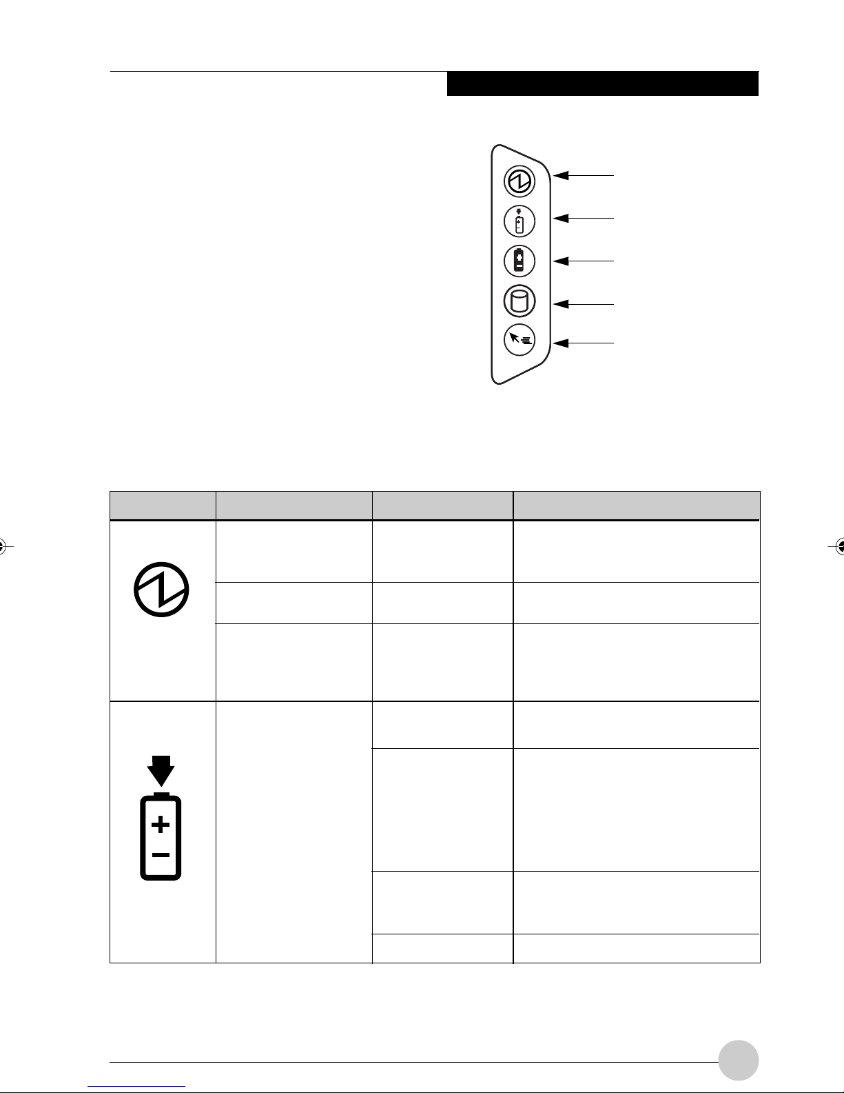
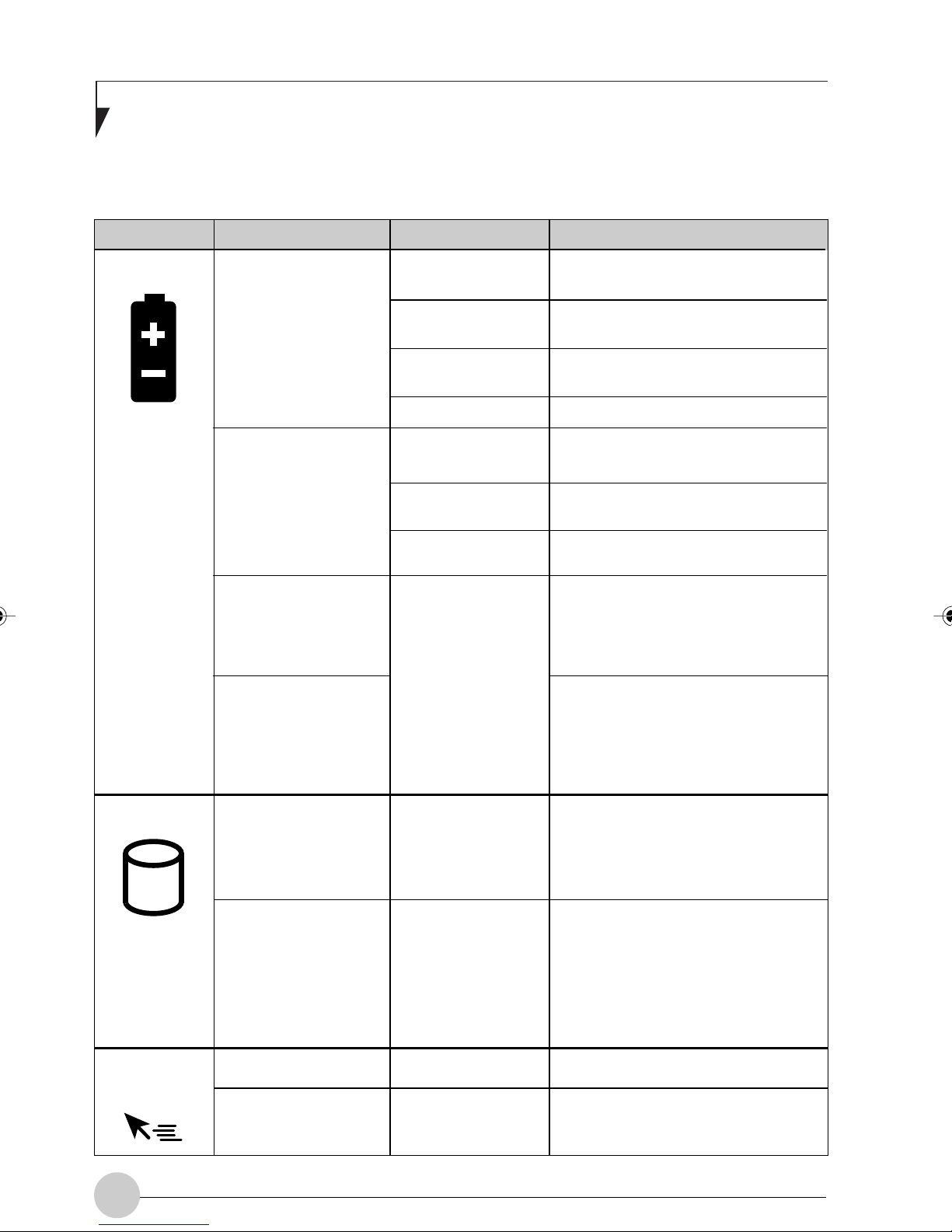
STATUS DISPLAY
Getting Started
Icons appear in the Status display indicating
the status of system functions such as system
power and battery charge level. The location of
icons in the Status display is shown in Figure
1-7.
Table 1-2 explains how individual icons are
displayed, and describes what the variations of
that display indicate. (If an icon is not
displayed, it indicates that the related system
function is off or inactive.
Power
Charge/DC In
Battery
HDD Access
Hovering Mode
Figure 1-7 Stylistic Display Icons
In the following table, a “blinking” LED flashes at the rate of once per second; an LED that is
“blinking, slow” flashes at the rate of one second on, five seconds off.
Icon Mode/State LED State Remarks
Power
• On State
• Idle Mode
Green, continuous
The system is powered on and
ready for use.
Charge/DC
In
• Suspend-to-RAM
• Off State
• Hibernate
(Save-to-Disk)
• On State
• Idle Mode
• Suspend-to-RAM
• Hibernate
(Save-to-Disk)
• Off State
Green, blinking
Off
Amber
Green
Amber , blinking
Off
The system has suspended and
saved active settings to RAM.
The system has suspended and
saved settings and data to the
hard disk drive.
AC adapter and battery are
available and system is charging.
• AC adapter and battery are
available and system is not
charging (battery fully
charged).
• AC adapter is available but
battery is not present.
AC adapter and battery are
available and w aiting to charge
(battery is out of thermal range).
AC adapter is not available.
9
Page 20
Fujitsu Stylistic ST4120P/21P Tablet PC User’s Guide - Section One
In the following tab le, a “blinking” LED flashes at the rate of once per second; an LED that is “blinking,
slow” flashes at the rate of one second on, five seconds off.
Icon Mode/State LED State Remarks
Battery
• On State
• Idle Mode
• Suspend-to-RAM,
without AC adapter
• Suspend-to-RAM,
with AC adapter
• Hibernate
(Save-to-Disk),
without AC adapter
• Off State
• Hibernate
(Save-to-Disk)
without AC adapter
• Off State
Green, continuous
Amber, continuous
Red, continuous
Red, blinking
Green, blinking
slow
Amber, blinking
slow
Red, blinking slow
Off
Battery charge is between 50% –
100%.
Battery charge is between 13% –
49%.
Battery charge is between 0% –
12%.
There is a battery error.
Battery charge is between 50% –
100%.
Battery charge is between 13% –
49%.
Battery charge is between 0% –
12%.
Battery is not installed, or system
is off or in Hibernate mode.
If battery is inserted during power
off, LED blinks amber for 4
seconds to detect battery. Battery
status is displayed for 5 seconds
after that.
HDD Access
Hovering
Mode
• On State
(or flasing)
• Idle Mode
• Suspend-to-RAM
• Hibernate
(Save-to-Disk)
• Off State
• Hovering mode
• Non-hovering
mode
10
Green
Off
Gree
Off
Displayed when hard disk driv e is
accessed.
Hard disk drive is not being
accessed.
Hovering mode is active.
Hovering mode is not active.
Table 1-2 System Status Indicators
Page 21
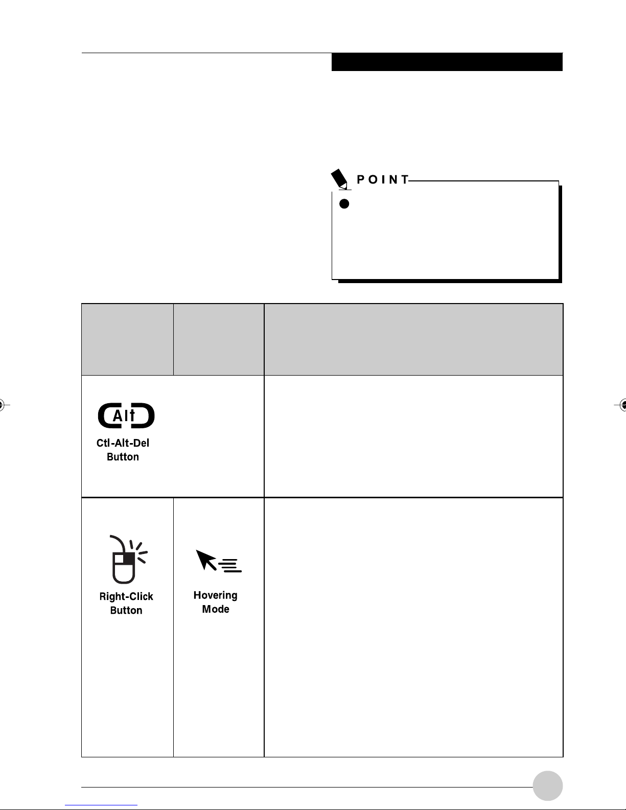
APPLICATION BUTTONS
Getting Started
The six application buttons are located on the
upper right-hand side of a vertically-oriented
system.
Four of the buttons ha ve secondary functions.
The secondary functions are activated by
pressing the Function (Fn) button while
pressing the application button.
The buttons also have separate tertiary
functions that can be used while the system is
(See figure 1-2 on page 4 for location)
Button Icon
and Name
(Primary)
Table Icon
(Fn +
Button)
(Secondary)
The Ctl-Alt-Del button performs two functions:
• Pressing the Ctl-Alt-Del button for two seconds al
booting up. For more information about the
tertiary functions, refer to Table 1-5 on page 14.
.
Ctl-Alt-Del is the only Application
button that can be used while the
system is logging on or when the
system is locked (i.e., when you have
the Logon or Computer Locked
window showing on your desktop).
Description
lows you to log on after boot, after locking the
workstation, or after resuming from power manage
ment.
• After log-on, pressing the Ctl-Alt-Del button for
two seconds launches the Windows Task Manager.
When you press the Right-click button, you pen switches its
function from left mouse button to right mouse button
emulation. To generate a right mouse button click, tap on the
application button once and then tap on the display.
When you press the Fn + Right-click buttons at the same
time, they provide a Hovering function. Hovering mode
provides you with better cursor control. When hovering is
enabled, the cursor can be positioned over an area of the
scree without activating it. This is useful when you are
attempting to read pop-up text associated with an icon,
simulating mouse rollover, selecting a small icon, or beginning
a paint session. Note that when Hovering Mode is active, the
Hovering Mode Status Display LED is lit (see Tab le 1-2).
Pressing the Fn + Right-click buttons at the same time again
exits the Hovering function.
11
Page 22

Fujitsu Stylistic ST4120P/21P Tablet PC User’s Guide - Section One
Button Icon
and Name
(Primary)
Table Icon
(Fn +
Button)
(Secondary)
Description
When you press the Orientation button, the system screen
orientation changes from portrait (vertical) to landscape
(horizontal) or from landscape to portrait. When you would like
to use the tablet as an eBook, for example, you would use the
portrait orientation, when accessing spreadsheets, you would
more typically use a landscape orientation.
The Escape application button acts the same way as an
Escape key on a keyboard.
When you press the Fn + Esc buttons at the same time*, they
act to invoke a pre-determined application or generate a
combination keystroke, as assigned the T ablet Button Settings
utility. (You can change the settings in Control Panel ->
Tablet Button Settings).
By default, pressing the Fn + Esc combination acts the same
as if you had pressed Ctl + Esc on a keyboard: the Start
menu is launched.
The Enter application button acts the same way as an Enter
key on a keyboard.
Pressing the Fn + Ent buttons at the same time*, acts to
invoke a pre-determined application or keystroke combination,
as assigned the Tablet Button Settings utility. (You can change
the settings in Control Panel -> Tablet Button Settings).
By default, pressing the Fn + Ent combination acts the same
as if you had pressed Alt on a keyboard: it selects a main
menu in the typical Windows application.
The Function button works in conjunction with the other
application buttons to provide additional functionality for the
buttons. Refer to specific details above.*
Pressing the Fn button twice in succession (within the “sticky”
time*), causes the Fujitsu menu to appear on your screen,
allowing you to modify certain system settings.
Table 1-3 Application Buttons - Primary and Secondary Functions
* The Fn button has a handy “sticky” feature that allows you to press the two buttons in immediate
succession, rather than at exactly the same time. After pressing the Fn button, you have a short
time (2 to 3 seconds) to press the second button. Note that this feature is not available with
the Right-Click/Hovering button.
12
Page 23
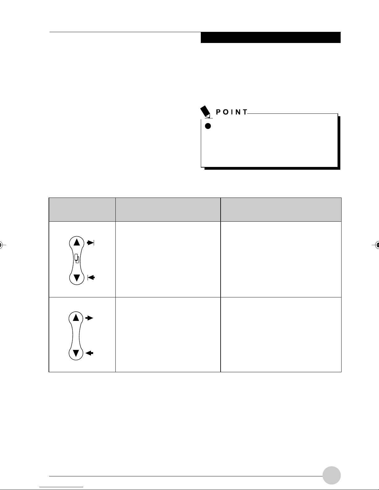
NAVIGATION BUTTONS
Getting Started
The two navigation buttons are located on the
lower right-hand side of a vertically-oriented
system.
Each of the buttons can be toggled by pressing
either end of the button.
The buttons have dual functions. The
secondary funtions are activated by pressing
the Function (Fn) button while pressing the
application button*.
The buttons also have separate tertiary
functions that can be used while the system is
(See figure 1-2 on page 4 for location)
Buttons/Icons Purpose (when pressed alone)
(“Primary” function)
This button consists of Up and
Down segments. When the Up
portion is pressed, you will scroll
up one page.
When the Down portion is
pressed, you will scroll down one
page.
.
booting up. For more information about the
tertiary functions, refer to Table 1- 5 on page 14.
Ctl-Alt-Del is the only Application
button that can be used while the
system is logging on or when the
system is locked (i.e., when you have
the Logon or Computer Locked
window showing on your desktop).
Purpose (when pressed with Fn button)
(“Secondary” function)
When pressed with the Function (Fn)
button*, the Up portion of this button
allows you to tab right.
When pressed with the Function (Fn)
button*, the Down portion of this
button allows you to tab left.
This button consists of Up and
Down segments. When the Up
portion is pressed, the cursor will
move up.
When the Down portion is
pressed, the cursor will move
down.
* The Fn button has a handy “sticky” feature that allows you to press the two buttons in immediate
succession, rather than at exactly the same time. After pressing the Fn button, you have a short
time (2 to 3 seconds) to press the second button. Note that this feature is not available with the
Right-Click/Hov ering button.
When pressed with the Function (Fn)
button*, the Up portion of this button
will move the cursor to the right.
When pressed with the Function (Fn)
button*, the Down portion of this
button will move the cursor to the left.
Table 1-4 Navigation Buttons
13
Page 24
Fujitsu Stylistic ST4120P/21P Tablet PC User’s Guide - Section One
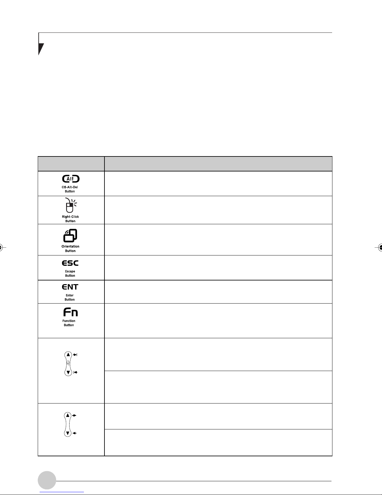
TERTIARY FUNCTIONS OF APPLICATION AND NAVIGATION BUTTONS
While you are booting up your system, the
Application Buttons and Navigation buttons can
be used for entering and navigating through the
Basic Input-Output System (BIOS), and for
invoking the Advanced Options Menu, where you
can enter different modes (such as Safe Mode).
The BIOS is a program and a set of parameters
that are stored in ROM which tests and operates
your Pen Tablet PC from when you turn it on until
it loads your installed operating system from disk.
Information from the BIOS is transferred to the
operating system to provide it with information on
the configuration and status of the hardware.
The system is booting up while the Fujitsu logo
is displayed immediately after turning on the
system. The table below indicates how the
buttons act while the system is booting up and
while you are in the BIOS.
Buttons/Icons
Purpose (when pressed while the system is booting up)
Pressing the Ctl-Alt-Del button while the system is booting up takes you
into BIOS setup. This is the same as if you had tapped [F2] on a ke yboard.
Pressing the Right-Click button while the system is booting up opens the
Boot Options menu. This is the same as if you had tapped [F12] on a
keyboard.
Pressing the Orientation button while the BIOS setup screen is open
causes the selected item (if applicable) to change to the next item. Pressing
this is the same as tapping the spacebar on a keyboard.
Pressing the Esc button while the BIOS is open acts to escape from the
BIOS. This is the same as if you had tapped [Esc] on a keyboard.
Pressing the Ent button while the BIOS is open acts the same as the [Ent]
button on a keyboard.
Pressing the Fn button while the system is displaying the operating system
boot menu opens the Advanced Operating System Options menu. This menu
allows you to enter different operating system modes (such as Safe Mode).
Pressing this button is the same as if you had tapped [F8] on a keyboard.
Pressing the top half of the upper navigation button while the BIOS setup
screen is open causes the cursor in the BIOS setup screen to move up.
This is the same as if you had tapped Arrow Up on a ke yboard. This f eature
is also functional in the operating system boot menu.
Pressing the bottom half of the upper navigation button while the BIOS
setup screen is open causes the cursor in the BIOS setup screen to move
down. This is the same as if you had tapped Arrow Down on a keyboard.
This feature is also functional in the operating system boot menu.
Pressing the top half of the lower navigation button while the BIOS setup
screen is open causes the cursor in the BIOS setup screen to move right.
This is the same as if you had tapped Arrow Right on a keyboard.
Pressing the bottom half of the lower navigation button while the BIOS
setup screen is open causes the cursor in the BIOS setup screen to move
left. This is the same as if you had tapped Arrow Left on a keyboard.
Table 1-5 Tertiary Functions of Application and Navigation Buttons
14
Page 25

Getting Started
CONNECTORS AND PERIPHERAL INTERFACES
Connectors and peripheral interfaces on the
Fujitsu Stylistic ST4120P/21P Tablet PC allow
connection of a variety of devices. Specific
locations are illustrated in Figures 1-2 through
1-5.
Connect/
Peripheral
DC input
connect
USB Port
PCMCIA
Card Slot
Microphone
jack
Headphone
jack
Tablet PC
Icon
Connect an external power source such as the AC adapter.
Connect Universal Serial Bus 1.1 compliant devices to the
Pen Tablet PC.
Install a Type I or Type II PC Card.
Connect an external microphone. The internal microphone
is disabled when you plug in an external microphone.
Connect stereo headphones or powered e xternal speakers.
The internal speaker is disabled when you plug in external
headphones or powered speakers.
Table 1-6 provides a description of each
peripheral connector on the Fujitsu Stylistic
ST4120P/21P Tablet PC. Each of the illustrated
icons is either molded into or printed on the
Tablet PC case.
Purpose
IrDA/FIR port
Modem
Tablet Dock
port
An infrared transceiver built into the Pen Tablet PC allows
you to communicate with other devices that are compliant
with the IrDA Standard Rev. 1.1. Effective range for infrared
communication is about 3 feet, and within 15 degrees off
center. A clear line-of-sight path must exist between the
IrDA port on the Pen Tablet PC and the IrDA transceiver on
the other device.
Connect a telephone line to the optional internal modem
using a standard RJ-11 telephone plug.
Connect the Fujitsu Stylistic ST4120P/21P Pen Tablet Dock
(optional device) or other approved docking device. Refer to
documentation accompanying the docking device for more
information.
15
Page 26

Fujitsu Stylistic ST4120P/21P Tablet PC User’s Guide - Section One
Connect/
Peripheral
Infrared
keyboard/
mouse port
Kensington
TM
Lock slot
IEEE 1394 jack
Suspend/
Resume button
Tablet PC
Icon
Purpose
An infrared receiver built into the Pen Tablet PC allows you
to communicate with a wireless infrared ke yboard or mouse.
The keyboard infrared port works optimally between 10 to
30 cm (approximately 4 in. to 12 in.) from the keyboard
infrared port, located on the bottom edge of the Pen Tablet
PC. Ensure that there is a clear line-of-sight path between
the infrared receiver on the Pen Tablet PC and the infrared
transmitter on the keyboard or mouse. (Optional device)
The Kensington™ Microsaver security slot allows you to
secure the Pen Tablet PC using Kensington-compatible
locking devices.
The IEEE 1394 jack allows you to connect between your
Pen Tablet PC and peripherals such as a digital video
camera.
The Suspend/Resume/Power On button allows you to
suspend Pen Tablet PC activity without powering off,
resume your Pen Tablet PC from suspend mode, and
power on the system when it has been shut down from
Windows.
Page Up/
Page Do wn
Local Area
Network (LAN)
Battery
Release
Latch
Wireless LAN
On-Off Switch
The Page Up/Page Down button allows y ou to navigate
quickly from page to page without scrolling.
The LAN (RJ-45) jack is used to connect the internal Fast
Ethernet (10/100 Base-T/Tx) to a Local Area Network
(LAN) in your office or home, or broadband devices such
as a cable modem, DSL, or satellite internet.
The battery release latch allows you to remove the battery
from your system for storage or replacement.
The wireless LAN switch allows you to turn power to the
wireless LAN device on and off.
Table 1-6 Peripheral Connectors/Interfaces
16
Page 27

22
2
22
Using Your
Fujitsu Stylistic
ST4120P/21P
Tablet PC
17
Page 28

Fujitsu Stylistic ST4120P/21P Tablet PC User’s Guide - Section One
18
Page 29

Using Your Stylistic ST4120P/21P
Using the Fujitsu Stylistic ST4120P/21P Tablet PC
This chapter covers the fundamental concepts,
basic system operation and use, and system
functions of the Fujitsu Stylistic ST4120P/21P
Tablet PC. You should familiarize yourself with
this information before you attempt to operate
the system.
Prior to using your system, be sure to
fully charge the battery if you plan to
run on battery power. Failure to do so
may result in erratic performance.
SYSTEM STATES
Before you begin using the Fujitsu Stylistic
ST4120P/21P Tablet PC, review the different
system states (or modes) that the system can
use. Being familiar with these states will help
you determine whether it is appropriate to turn
on, resume, suspend, hibernate or shut down
the system when you begin or end a session.
System behavior for each system state is
described briefly in the following, with each
system state listed in decreasing order of
power usage:
Suspend-to-RAM mode. Refer to the
“Resuming System Operation” section later
in this chapter for information on returning
the system to the On state.
• Hibernate mode (Save-to-Disk) (S4):
System operation is suspended. All system
functions are turned off to conserve power.
Active data in programs that were running
before suspending system operation is
stored on the hard disk drive. The system
does not respond to the pen or other input.
Refer to the “Resuming System Oper ation”
section later in this chapter for information
on returning the system to the On state.
• Off state: All system functions are turned off
to conserve power. The system does not
respond to the pen or other input. The
system boots at the next system power-on.
The system consumes the same
amount of power whether it is in
Hibernate (Save-to-Disk) mode or the
Off state.
• On state: The system is running and the
display screen is on.
• Idle state: Some system functions are
regulated or turned off to conserve power.
The display screen may be turned off. The
system returns to the On state when pen
activity or other input is detected.
• Suspend-to-RAM mode (S3): System
operation is suspended. Most system
functions are turned off to conserve power.
Power to memory is on, maintaining data in
programs that were running before system
operation was suspended. The system does
not respond to the pen or other input when in
Your system may be configured to enter some
of these states automatically after a period of
inactivity to conserve battery power.
When you use the Fujitsu Stylistic ST4120P/
21P Tablet PC, you can change the current
system state in a number of ways, depending
on the system’s current state. To determine the
current system state, observe the Power icon
in the Status display. Table 2-1 on page 20
gives the different system states represented
by the Power icon and describes how you can
change the system state from the current state.
19
Page 30

Fujitsu Stylistic ST4120P/21P Tablet PC User’s Guide - Section One
Icon Apperance
Power icon
displayed
continuously
Power icon
blinking
Power icon not
displayed
Current State
On State
or
Idle State
Suspend-toRAM❖
Off State, or,
Hibernate
(Save-to-Disk❖)
To enter the Off state, shut down the system using the
Start menu on your system.
To enter Suspend-to-RAM or Hibernate (Save-to-Disk) ❖
state, suspend system operation using either a hardware or
software suspend.
To enter the On state, resume system operation by
pressing the Suspend/Resume button.
To enter the Off state, resume system by pressing the
Suspend/Resume button, then shut down your system.
To enter the On state, start your system, or resume system
operation by pressing the Suspend/Resume button.
Purpose
Table 2-1 Changing System States
* Information in Table 2-1 on page 20 is supplied to help you understand which system states your
system can enter from the current system state. Refer to the procedures on starting the system,
shutting down the system, suspending system operation, and resuming system operation given
later in this chapter.
❖ Your system may be configured to use either Suspend-to-RAM mode or Hibernate mode.
POWERING UP THE PEN TABLET PC
Follow the procedure below to start the Fujitsu
Stylistic ST4120P/21P Tablet PC. Before you begin,
confirm that the system is in the Off state. To do so,
observe the Status display. If the Power icon is not
visible in the Status display, the system is in Off
state or in Hibernate (Save-to-Disk) mode and it is
safe to perform this procedure. If the Power icon is
visible (either blinking or on continuously), do not
perform this procedure. See “System States” earlier
in this chapter for details on modes represented by
the Power icon.
1. Ensure that the battery in your Pen Tablet PC is
sufficiently charged, or connect an external power
source such as the AC adapter to your Pen Tablet
PC.
2. Press the Power On/Suspend/Resume button to
start the system.
1. If system operation has been suspended, resume
system operation. See “Resuming System Operation” later in this chapter for details.
2. Save your work and close all running programs.
3. Choose Shut Down from the Windows Start
menu.
4. Carry out the Shut Down command.
The system is now in the Off state.
SUSPENDING SYSTEM OPERATION
The Pen Tablet PC allows you to suspend the
system operation without closing programs or
exiting the operating system. Use this feature to
conserve battery power when a system shutdown is
not practical or when the battery needs to be
changed.
After performing initialization, the system starts the
operating system installed on the hard disk drive.
Once the operating system is running, you can use
the system.
SHUTTING DOWN THE SYSTEM
Follow these steps to shut down and turn off your
system:
20
If you have set your system to turn power
off from the P ower Options utility in the
Control Panel, the following procedure will
not be possible, since pressing the button
shuts the system down rather than
suspending it. To change your power
options, go to Start -> Settings -> Control
Panel -> Power Options.
Page 31

Using Your Stylistic ST4120P/21P
To suspend system operation:
1.
Press the Suspend/Resume button, or carry out
the Standby command from your operating
system or power management progr am.
(If your system is configured to suspend
operation using Hibernate (Save-to-Disk)
mode, which is explained later in this
procedure, a message is displayed while data
is saved to your hard disk.)
If you are replacing the battery, wait until
system operation is suspended and the
power icon is flashing before you remove the
battery. Failure to do so could result in loss of
your unsaved data. (Note that if the Resume
On LAN function is enabled in the BIOS setup,
you should not remove the battery unless the
system is shut down. When Resume ON LAN
is enabled, the bridge battery is disabled in
order to optimize battery life.)
2. The Power icon either flashes (Suspend-toRAM) or is not displayed (Hibernate) when
system operation is suspended, depending
on how your system is configured. At this
point, programs that were running are
stopped, active data is saved, and the system
enters one of two different low-power states,
or suspend modes, as explained in the
following paragraphs.
Operation” later in this chapter to resume
system operation. Also, note the following
with regard to suspending system operation:
•
You can remove the battery while the system is
in Suspend-to-RAM or Hibernate modes in
order to install a charged battery. To prevent
losing unsaved data, wait until system operation
has suspended before you remove the battery.
Note that after you remove the battery, you have
approximately five minutes to replace it with a
new battery or to plug in a power supply before
the bridge battery is depleted.
• Your system may be configured to suspend
operation automatically after a period of
inactivity.
• Your system may be configured to enter
Hibernate mode automatically after a period
of time in Suspend-to-RAM mode.
• The system uses a small amount of battery
power when in Suspend-to-RAM mode.
Eventually, the battery will become fully
discharged.
If you will not be using the system for an
extended period of time, shut down the
system rather than using Suspend-toRAM mode.
3. Observe the Power icon in the Status display
to determine which suspend mode your
system is using.
•
Power icon is b linking: Suspend-to-RAM mode.
In this mode, active data is saved by
maintaining power to RAM while most other
system components are powered off. The
Battery Gauge icon in the Status display
indicates the battery charge level.
• Power icon is not displayed: Hibernate
(Save-to-Disk)
In this mode, active data is stored on the hard
disk drive and power usage is reduced to the
same level used in the Off state. When the
system is in Hibernate mode, the Battery
Gauge icon is not visible in the Status displa y.
In this mode, there is no danger of losing
data if battery power is lost.
If you have successfully performed this
procedure, system operation is now
suspended. Refer to “Resuming System
mode.
• If the battery charge drops to a Low-Battery
Warning level while the system is running, the
system will beep periodically. If this occurs,
suspend system operation, shut down the
system, or attach an external power source,
such as the AC adapter, to the Pen Tablet PC.
• If the battery charge drops to a Critically Low
level while the system is running, the system
is forced into a pre-selected mode (Suspendto-RAM or Hibernate). If this occurs, you must
either install a charged battery, or connect an
appropriate external power source such as
the AC adapter before you can resume
system operation. (If the battery charge drops
to a Critically Low level while the system is in
Suspend-to-RAM mode, the system stays in
Suspend-to- RAM mode until power is
restored or totally dissipated.)
• Suspending system operation interrupts data
communications; therefore, some programs
may b lock the system from suspending to
prevent an interruption.
21
Page 32

Fujitsu Stylistic ST4120P/21P Tablet PC User’s Guide - Section One
• The suspend action of the Suspend/Resume
button may be disabled to prevent accidental
interruption. If this is the case, pressing the
Suspend/Resume button will not suspend
system operation as described here. (In this
case, suspend mode can only be achieved
using the system software). Contact your
local help desk or reseller if your system
configuration is not suitable.
•
If your system is equipped with a PC Card that
allows you to connect to a wired or wireless
network, you may be logged off the network
after a period of inactivity while system
operation is suspended. Contact your network
administrator or help desk for details on log-off
parameters for your network.
RESUMING SYSTEM OPERATION
To resume system operation from either
Suspend-to-RAM or Hibernate modes, press the
Suspend/Resume button.
• From Suspend-to-RAM mode
Status lights indicate that the system state is
changing. It may take up to a minute before the
system returns to the On state and system
operation resumes. Note that the display turns on
shortly before the pen becomes active due to the
power-up sequences observed by the system.
• From Hibernate (Save-to-Disk) mode
Active data is read from the hard disk drive,
and the system returns to the On state after a
short time.
USING THE PEN
You can use the Fujitsu Stylistic ST4120P/21P
Pen to select items, and to navigate through
programs on the Pen Tablet PC. The pen can
be used like a two button mouse when used in
conjunction with the right-mouse button.
• Ensure that a screen protector is
installed on the Pen Tablet PC screen
before you use the pen. The warranty
does not cover a screen that is
scratched as a result of not using a
screen protector.
• Use only the pen provided with your Pen
Tablet PC. Do not use substitutes that
were not designed for the Fujitsu
Stylistic ST4120P/21P Tablet PC. (e.g.,
ball point pens, fingernail, or
screwdriver). Damage caused by using
an instrument other than the provided
pen is not covered by the system
warranty.
Here are some hints on using the pen similar to a
two-button mouse on a desktop system:
• To select an object, tap the pen tip on the
object once. This functions like a left mouse
button click.
Note that power to several system
components must be restored before
system operation resumes. Allow
sufficient time for system operation to
resume before attempting to use the
system. If your system uses Hibernate
mode, it will take longer to resume
operation as compared to using Suspendto-RAM mode. Time is needed to read
data from the hard disk drive.
• Use the system as you normally would once
system operation resumes.
All programs resume at the point where execution
stopped when system operation was suspended.
22
• To “double-click” an object, tap twice on
the object quickly. (The pen double-click
speed is in sync with the mouse double-click
speed, and can be changed by going to
Start -> Settings -> Control Panel -> Mouse.
• To generate a “right mouse button singleclick”, press the Right-Click Application
Button , then tap on the object once.
• To move, or “drag”, an object on the
screen, place the pen tip directly over the
object, then as you hold the pen tip against
the screen, move the pen.
Page 33

Using Your Stylistic ST4120P/21P
INSTALLING A PEN TETHER
To prevent dropping or losing your pen, you
should attach it to your system using the pen
tether. (Pen tether is not provided)
To attach the pen tether to your Tablet PC,
perform the following steps:
1. Attach the end of the pen tether with the
clasp to your pen. To do so push the end of
the tether through the hole in the pen, then
thread the opposite end of the tether through
the loop.
NOTE:
The figure below may not be an exact pictorial
representation of the Pen Tether and your Pen
Tablet PC.
(See Figure 2-4.)
Pen tether
attachment
point
Figure 2-4. Installing a Pen Tether
2.
Attach the other end of the pen tether to the
attachment point on your Pen Tablet PC. To do
so, insert the end of the pen tether through the
attachment point, then feed the pen through
the large loop in the tether.
CALIBRA TING THE PEN
Calibration of the pen adjusts the cursor
position on the screen relative to the position of
the pen tip. You calibrate the pen to adjust the
distance error between where the pen actually
touches the screen and where the system
“thinks” the pen is touching. If the event you
wish to invoke is not displayed under the pen
tip when you use the pen, you should calibrate
the pen.
Pen calibration may be required due to the
following situations:
• The pen is being used for the first time.
• The previous user of the Fujitsu Stylistic
ST4120P/21P Tablet PC writes with the
opposite hand or at a different pen angle.
• The system has been in use for some time
and the pen has not been recalibrated.
• The original system image has been
restored.
To Calibrate the Pen
1. Open the Control Panel from the Start |
Settings menu, and double-tap the Pen
Configuration icon. In the Setup Property
page, tap on [Calibrate] to start calibration.
2. Position the Fujitsu Stylistic ST4120P/21P
Tablet PC as you normally would during use.
Be sure to hold the pen at the angle that you
regulary use. Touch the screen only with the
pen tip; inadvertently touching the screen
with your finger or hand during the
calibration process, ma y result in faulty
calibration.
3. Perform the calibration steps according to
the instructions on the screen. The
calibration utility displays a cross-hair
symbol in the corners of the screen, one
corner at a time. Hold the pen as you
normally would while using the system and,
as accurately as possible, tap the center of
each crosshair as it is displayed.
4. When the Verify New Pen Calibration
Settings window appears, choose one of the
following steps.
• If you are satisfied that you tapped the
cross-hairs accurately, tap Yes. The taps
that you performed in step 3 are then used
to calibrate the screen.
• If you do not want to use the new
calibration, tap No.
• If you want to enter a new calibration, tap
Recalibrate. The calibration instructions
reappear.
• If you don’t tap the screen within 20
seconds, the default settings will be used.
If you have successfully performed the
procedure above, the pen is now recalibrated,
and can use the system as you normally
would.
23
Page 34

Fujitsu Stylistic ST4120P/21P Tablet PC User’s Guide - Section One
Replacing the Pen
With use, the pen tip may become worn or may
pick up foreign particles that can scratch the
screen. A damaged or worn tip may not move
freely, causing unpredictable results when
using the pen. If your pen exhibits these
problems, contact your reseller to purchase
replacements.
USING HOVERING MODE
Selecting the Pen Hovering application button
on the Fujitsu Stylistic ST4120P/21P Tablet PC
provides you with better cursor control. When
the hovering option is enabled, the cursor can
be positioned over an icon without activ ating it.
The is useful when you are performing
procedures that require accurate cursor
positioning, such as when simulating mouse
rollover, selecting a small icon, or beginning a
paint session.
• To enable hovering, press the Function
button and the Right-Click button
at the same time.
2. Look at the Battery Gauge icon in the Status
display to determine the percent of charge in
the battery. See “Status Display” in Chapter
1 of this manual for a description of the
Battery Gauge icon.
As long as DC power remains connected to the
Pen Tablet PC, the charging process continues
until the battery charge reaches 100%. Charge
times shown in Table 2-3, “Battery Charging
Time" are for a fully discharged battery
charging both while the Pen Tablet PC is and is
not in use.
Battery Charge
Level Reached
90%
100%
Approximate
Charge Time
(not in use)
3.5 hours
4.5 hours
Approximate
Charge Time
(in use)
7 hours*
8 hours
Table 2-3 Battery Charging Time
• To disable hovering, press the Function
button and the Right-Click button
again.
For help on Normal/Special Hover mode
settings in the Pen Configuration applet, press
[F1] to invoke help from within the applet.
CHARGING THE BA TTER Y
The Fujitsu Stylistic ST4120P/21P Tablet
battery can be charged while it is installed in
the Pen Tablet PC.
To do so:
1. Connect a DC power source, such as the AC
adapter, to the DC input connector on the
Pen Tablet PC. The DC Input icon appears in
the Status display. If the battery charge is
below 90%, the battery begins charging and
the Charging icon appears in the Status
display. If the battery charge is 90% or
higher when you connect DC power, the
battery will not charge, preventing battery
overcharging.
Also note the following with respect to charging
the battery:
• You can use the system, suspend system
operation, or shut down and turn off the
system without interrupting the charging
process; however, using the system while
the battery is charging will cause the battery
to charge at a slower rate, as noted in Table
2-3, “Battery Charging Time".
• As noted in the procedure above, the system
will not begin charging the battery if the
battery charge level is 90% or higher when
the system is initially connected to external
DC power. (This prevents the battery from
being overcharged.)
• The Fujitsu Stylistic ST4120P/21P Tablet
battery uses Lithium ion battery cells which
have no “memory effect.” You do not need to
discharge the battery before you begin
charging.
24
Page 35

Using Your Stylistic ST4120P/21P
REMOVING AND INSTALLING THE
BATTERY
The battery can be removed from the Pen
Tablet PC and swapped with a charged battery.
The battery can then be charged in an external
charger if one is available. To remove the
battery from the Pen Tablet PC:
1. Choose one of the following:
• If a charged battery is available, you can
suspend system operation. A built-in
“bridge” battery will maintain the system in
Suspend-to-RAM mode for about 5
minutes while the battery is removed; this
allows time for replacement with a
charged battery.
• If a charged battery is not available, save
your work and close all running programs,
then shut down the system or Hibernate
(Save-to-Disk).
• Plug in an external DC power source.
2. Slide the battery release latch in the
direction indicated.
for location)
3. Pull the battery away from the system, as
shown in the illustration and remove the
battery from the Pen Tablet PC.
If you are using an external battery charger,
refer to the instructions provided with the
battery charger.
To install the battery:
1. Orient the battery with the slides in the
empty battery tray. Slide the battery into the
tray and press it firmly until it is seated.
When it is properly seated, the battery
release latch should return to position and
lock the battery.
.
(See Figure on page 25
Once the battery is installed, you can resume
system operation or start and use your system
normally.
TIPS FOR CONSERVING BATTERY
POWER
You can extend the charge life of your battery
by conserving battery power. (Your results may
vary depending on your application and how
the system is configured.) Here are some
suggestions to help you conserve battery
power:
• Use an external power source such as the
AC adapter whenever the system is docked.
• Suspend system operation if you know that
you won’t be using the system for a while.
• Shut down the system if you won’t be using
the system for an extended period of time.
• Use power management (available on the
desktop) to help you conserve power
automatically.
• Battery life is dependent upon the operating
system, power settings, and applications in
use.
Operation of the Bridge Battery
When installed in the Pen Tablet PC, the
battery provides power to some system
components—even when the system is in the
Off state. When the battery is removed, power
is supplied to these components by a “bridge”
battery that is built into the Pen Tablet PC.
The bridge battery is not designed for longterm operation. To maintain the bridge battery
properly, observe the following measures:
Figure 2-2 Removing the Battery
The bridge battery function is disabled
if Wake On LAN is enabled in the BIOS.
The system arrives with the bridge
battery in a discharged state. Be sure to
charge it sufficiently before relying upon
it to support the system in the event of
battery removal.
25
Page 36

Fujitsu Stylistic ST4120P/21P Tablet PC User’s Guide - Section One
• To prevent draining the bridge battery,
always store the system with a charged
battery installed.
• If the bridge battery becomes drained, it
takes approximately 8 hours for it to be fully
recharged.
• The bridge battery charges when the AC
Adapter is connected and the system is in
On or Off states or Suspend mode. It
charges from the battery only when the
system is in the On state.
MODEM CONNECTION
The Fujitsu Stylistic ST4120P/21P Tablet PC is
designed to accept a standard RJ-11
telephone plug. Connect the plug to the
modem jack located on the left-hand side of
the Pen Tablet PC
for location)
installed whether or not the Pen Tablet PC has
power applied.
If you need assistance configuring the Fujitsu
Stylistic ST4120P/21P Tablet PC modem or
LAN, contact your local help desk or your
reseller.
. The telephone plug can be
(See Figure 1-4 on page 7
PC CARD SLOT
The Fujitsu Stylistic ST4120P/21P Tablet PC
Card slot allows you to install a Type I or Type
II PCMCIA Card.
Removing a PC Card
To remove a PC Card, press the PC Card eject
button so that it pops out. Once the button has
popped out, press it firmly to eject the card.
(See Figure 2-4 for location)
Figure 2-4 Removing a PC Card
REMOVING AND INSTALLING
MEMORY MODULES
There is one DIMM slot in your Pen Tablet PC
and 256MB on the motherboard. 256MB and
512MB modules are available, so you can
install a combination of up to 768MB in the
system.
Installing a PC Card
To install a PC card, position the side with the
arrow facing up (i.e., when looking at the
tablet’s display side, the arrow on the card
should be visible.) Slide the card into the PC
Card slot, and press it firmly to ensure proper
seating.
If you need assistance installing a PC Card in
the Fujitsu Stylistic ST4120P/21P Tablet PC,
contact your corporate help desk or your
reseller.
(See Figure 2-3 for location)
Figure 2-3 Installing a PC Card
26
DIMM replacement should only be
performed at a static-free workstation.
Avoid touching connector pins, circuit
boards, or other circuit components on the
drive or P en Tablet PC. Electrostatic
discharge caused by doing so can damage
sensitive components.
Page 37

Using Your Stylistic ST4120P/21P
Installing a Memory Module
To install a DIMM module in the Pen Tablet PC:
1. Ensure that the Pen Tablet PC is off. To do
so, carry out the Shut Down command in the
Start menu. (Do not attempt to remove or
install a DIMM module when the system is in
Suspend mode or running.)
2. Remove the two screws from the cover plate
on the back of the Pen Tablet PC and
remove the cover plate as shown in Figure
2-5.
Figure 2-5 Accessing the Memory Slot
Removing a Memory Module
To remove a DIMM module:
1. Ensure that the Pen Tablet PC is off. To do so,
carry out the Shut Down command in the Start
menu. (Do not attempt to remove or install a
DIMM module when the system is in Suspend
mode or running.)
2. Remove the screws from the cover plate on
the back of the P en Tablet PC and remove the
cover plate as shown in Figure 2-5.
3. Spread the fingers on the socket that lock the
DIMM module in place until the DIMM module
is loose.
4. Remove the DIMM module from the socket.
The DIMM module is now removed from the P en
T ab let PC. Refer to “Installing a Memory Module”
on page 27 to install a new DIMM module.
3. Insert the DIMM module in the socket at an
angle and push it down until it locks into place
as shown in Figure 2-6. Note that the DIMM
module is keyed to prevent it from being
inserted backwards.
Figure 2-6 Installing a DIMM Module
4. Reinstall the cover and screws that you
removed in step 2.
5. Confirm that the DIMM module is recognized
by the system. To do so, run BIOS Setup . The
size of the DIMM module should be displayed
in the Info menu in BIOS Setup.
The DIMM module is installed in the Pen Tablet
PC and you can now use the system.
27
Page 38

Fujitsu Stylistic ST4120P/21P Tablet PC User’s Guide - Section One
28
Page 39

33
3
33
Care and
Maintenance
29
Page 40

Fujitsu Stylistic ST4120P/21P Tablet PC User’s Guide - Section One
30
Page 41

Care and Maintenance
Care and Maintenance
This chapter gives you pointers on how to care
for and maintain your Fujitsu Stylistic
ST4120P/21P T ablet PC.
PROTECTING THE DISPLAY SCREEN
The Fujitsu Stylistic ST4120P/21P Tablet PC is
designed to provide you with years of service.
Using a screen protector will help ensure that
the screen remains as clear as possible. When
installed, the screen protector becomes a
durable, replaceable writing surface that
protects the display screen from abrasion.
NOTE:
The Screen Proctector is sold separately,
please check with your dealer.
During normal use of the Pen Tablet PC,
small particles from the environment can
become embedded in the pen tip and
scratch the screen. To prevent scratching
the screen, ensure that a screen protector
is installed before using your Pen Tablet
PC. The warranty does not cover a screen
that is scratched as a result of not using a
screen protector.
To install a new screen protector on your Pen Tablet
PC:
1. If a screen protector is already installed on
the display screen, remove it before installing
the new screen protector.
3. Remove the protective coating from the
adhesive side of the screen protector first,
as shown in Figure 3-1.
• The Fujitsu Stylistic ST4120P/21P Tablet
PC is not water- proof. Do not pour liquids
on the system or wash it with a heavily
soaked cloth.
• Do not place items on the top of the display,
or damage may occur.
Figure 3-1 Removing the Protective Sheet
4. Apply the screen protector to the display
screen surface. When doing so, orient the
screen protector with the adhesive side of
the screen protector facing the display
screen and the notched corner of the screen
protector oriented as shown in Figure 3-2.
The screen protector is held onto the display
screen surface by a thin strip of adhesive
around the edges. A notch in one corner of
the screen protector allows you to slide your
fingernail under the screen protector for easy
removal.
2. Clean the display by wiping the screen
gently using a soft cotton cloth dampened
with isopropyl alcohol. Ensure that all residue
has been removed from the screen before
applying a new screen protector.
Figure 3-2 Installing the screen protector
31
Page 42

Fujitsu Stylistic ST4120P/21P Tablet PC User’s Guide - Section One
5. Apply pressure to the screen protector with
your finger using a continuous wiping motion
along the edges. The adhesive sets
completely within 48 hours. To ensure a
good seal between the screen protector and
the display, do not lift the screen protector
from the display once it has been applied.
6. Remove the protective plastic cover from the
face of the screen protector, as shown in
Figure 3-3.
Figure 3-3 Installing the screen protector
7. Clean any residue left behind by the
protective coating from the exposed surface
of the screen protector by wiping gently with
a soft cotton cloth dampened with isopropyl
alcohol. Wipe the screen protector with a
soft dry cloth to remove any low-tack
adhesive; this will help prevent the pen tip
from squeaking.
The screen protector is now installed.
STORING THE T ABLET PC
Store the Fujitsu Stylistic ST4120P/21P Tablet
PC in the Off state with a fully charged battery
installed. You can store the Pen Tablet PC in
the Off state for about 30 days with a fully
charged battery installed. After this period, the
battery should be recharged or replaced with a
charged battery.
If you intend to store the Pen Tablet PC for a
longer period of time, the small battery that
maintains system time may need to be
replaced. Replacement of the clock battery
should only be performed by authorized
technicians.
AVOIDING OVERHEATING
The Pen Tablet PC monitors its internal
temperature. As the internal temperature
approaches the tolerable limits of heat-sensitive
components, system functions are
automatically limited or turned off to prevent
damage.
To avoid overheating the Pen Tablet PC, do not
obstruct the air vents on the top and bottom
edges of the Pen Tablet PC.
CLEANING THE DISPLAY SCREEN
To clean the Pen Tablet PC display screen,
wipe the screen surface gently using a soft
cotton cloth slightly dampened with water or
isopropyl alcohol.
The Fujitsu Stylistic ST4120P/21P Tablet
PC is not waterproof. Do not pour liquids
on the Pen Tablet PC or wash the Pen
Tablet PC with a heavily soaked cloth.
TROUBLESHOOTING
Solutions to some common problems are
described in the following sections. If you are
experiencing a problem with your Pen Tablet
PC that you cannot solve by taking the actions
described, contact your local help desk or your
reseller for further assistance.
System Will Not Resume Operation
If the system will not resume operation after
system operation has been suspended, check
the following possib le causes:
• The battery may either be defective, or
discharged to a critically low level. When the
battery reaches a critically low level, the
system is forced into Suspend-to-RAM mode
to avoid a total system power failure. To
correct this problem, either connect an
external power supply (such as the AC
adapter), or install a charged battery in the
T ab let PC.
• The system may be at the critical thermal
limit. To avoid damage to heat-sensitive
components, the system enters Suspend-toRAM mode when it gets too hot. System
operation cannot be resumed until the Pen
Tablet PC cools off to a tolerable
temperature. Move the Pen Tablet PC to a
cooler locatio
n.
32
Page 43

Care and Maintenance
Display Screen Blank or Difficult to Read
If the display screen on your Pen Tablet PC
appears blank
the system is running (the Power icon is
displayed continuously on the Status display),
and check the following:
• The system brightness may be set too low,
causing the screen to appear too dark. To
change system brightness, press the Fn
button twice to open the Fujitsu menu.
Brightness can be adjusted from the menu.
• The video timeout may have expired. Tap on
the display screen to reactiv ate the display.
Note that this is a normal, power-saving
feature.
Cursor Is Not Tracking Pen
If the cursor on the screen appears to be misaligned
with the pen or is not accurately tracking the pen,
calibrate the pen.
Infrared Data Transfer Is Not Working
or
is unreadable, confirm that
Pen Tablet PC is Not Responding to the Pen
If the Pen Tablet PC does not respond to the
pen, connect an external keyboard to the
system to see if it responds to keyboard
commands. If the system doesn’t respond to a
keyboard, the application or system may have
crashed, and it may be necessary to reset the
system. If the system responds to a keyboard
but not to a pen, contact your local help desk
or reseller for further assistance.
Speaker/Headphone V olume T oo Low
If the audio volume on your Pen Tablet PC
speaker or external headphones is too low,
check the follo wing:
• Ensure that the speaker (or headphone
output if using headphones) is enabled. To
do so, open the Control Panel and doubleclick on the Sounds and Audio Devices icon.
Select the proper tab, and increase the
volume using the slider bar. (If you aren’t
getting any sound, uncheck the Mute box if it
is checked.)
If you are experiencing problems transferring
data over the system’s infrared interface, note
the following:
• Can the IrDA port on the Pen Tablet PC
“see” the IrDA port on the other device? A
direct line-of- sight path must exist between
the IrDA port on the Pen Tablet PC and the
IrDA port on the other device.
• The distance between the two devices must
not be more than 3 feet.
• The viewing angle from the IrDA port on the
Tablet PC must not be more than 15
degrees from a center line between the IrDA
port on the Pen Tablet PC and the IrDA port
on the other device.
• The device with which you are trying to
communicate must be compliant with the
IrDA Standard Re vision 1.1 (or 1.0).
• It may be necessary for both computers to
be using the same network connection
protocols.
• Press the Fn button twice to open the Fujitsu
menu. Volume can be adjusted from the
menu.
• Ensure that the mute box in the system
volume control (accessible from the system
tray) is not set.
• Ensure that any volume control in your audio
software is set to an audible le vel.
Configuring Peripheral Interfaces
Certain peripheral devices can be disabled
during the BIOS Setup. If the peripheral
interface you want to use does not appear to
be working with your peripheral device, ensure
that it is enabled in the BIOS. Contact your
local help desk or reseller if you need
assistance using BIOS Setup.
33
Page 44

Fujitsu Stylistic ST4120P/21P Tablet PC User’s Guide - Section One
34
Page 45

44
4
44
Specifications
35
Page 46

Fujitsu Stylistic ST4120P/21P Tablet PC User’s Guide - Section One
36
Page 47

System Specifications
Fujitsu Stylistic ST4120P/21P Hardware Specifications
The following table provides general hardware
specifications of the Fujitsu Stylistic ST4120P/
21P Tablet PC by category.
Stylistic ST4120P/21P Specifications
Physical Specifications
Dimensions
Weight
Processing Specifications
CPU
Chip set
Processor
Speed
Memory/Storage Specifications
Main RAM
11.86" w x 8.66" d x 0.82" -88" h
301.3mm x 220mm x 20.9-22.3mm
The weight of a T ransmissive P assive
(ST4120P) is 1.45Kg (3.2lbs) and a
Reflective Passive (ST4121P) is
1.5kg (3.49lbs).
Ultra low voltage Mobile Intel P entium
III processor - M with SpeedStep
technology*
Intel 830MG - 133 MHz
933 MHz*
• 256MB SDRAM (on-board/PC133).
Stylistic ST4120P/21P Specifications (Continued)
Display Specifications
Display
VRAM
• Color LCD
• P assive Touch Panel
LCD Type :Transmissive
or Reflective w/ Frontlight*
• 16-bit color
• 10.4” TFT XGA (1024 x
768), 260K colors
• Brightness: 8 levels
• Viewing Angle:
Horizontal: 30 degrees (min.)
Vertical: 10 degrees (min.)
• Contrast Ratio:
Typ. 250, Min. 100
Intel 830MG chipset with 8MB
shared memory using Unified
Memory Architecture (UMA)
delivers low-power, highperformance 3D/2D graphics,
video, and displa y capabilities .
Dynamic Video Memory
Technology (DVMT) dynamically
responds to application
requirements and efficiently
allocates the proper amount of
memory (48MB max.) for optimal
graphics and system performance.
• 144-pin SO DIMM modules
256MB and 512MB module
configurations available, with a
system maximum of 768MB.
L1 cache
(CPU)
L2 cache
BIOS ROM
Hard disk
drive
32 KB on-die
512 KB on-die
1 MB (FWH)
• 2.5” HDD
• Minimum 30GB IDE HDD*
• Ultra DMA 100
• Shock-mounted
PC Card
Slots
Integrated
Interfaces
Infrared
Interface Specifications
• One Type I or Type II
• PCMCIA CardBus version 3.0
• Modem (RJ-11)
• LAN (RJ-45)
• IEEE 1394 (S400 4-pin)
• USB (Qty. 2)
• DC-In
• 15-pin D-SUB connector for
external VGA monitor
• Docking connector
IrDA v ersion 1.1 (FIR, 4Mbps)
37
Page 48

Fujitsu Stylistic ST4120P/21P Tablet PC User’s Guide - Section One
Stylistic ST4120P/21P Specifications (Continued)
Keyboard/
Mouse
support
Audio
User
Controls
Status
Indicators
(LEDs)
• Keyboard/Mouse IR Port
• System IR Port
• SigmaTel STAC9767 codec
• Internal mono microphone
and speaker
• Mono microphone and stereo
headphone jacks
• Application Buttons, each
with primary, secondary , and
tertiary functions
• Pow er On/Suspend/Resume
button
• Emergency Shutoff Button
(Power Off button)
• Two Navigation buttons
• Power
• Charge/DC-In
• Battery level
• HDD
• Hovering
Stylistic ST4120P/21P Specifications (Continued)
Bridge
Battery
AC Adapter
Environmental Specifications
Temperature
Humidity
Agency Approval Specifications
• 6-cell NiMH, 35 mAH
• Life (with Suspend-to-Ram
on bridge battery only):
5 minutes from full charge.
• Autosensing 100-240V,
supplying 16 VDC, with a
current of 3.75A.
• Mono microphone and stereo
headphone jacks
Operating: 41˚ - 95˚ F
(5˚ - 35˚ C)
Non-operational: 5˚ - 140˚ F
(-15˚ - 60˚ C)
Operating: 20 - 85% noncondensing
Non-operating: 8 - 85% noncondensing
* The specifications for your particular model
may vary. To determine the specifications for
your system, please visit our web site at:
www.fujitsu-pc-asia.com
Power Specifications
Main Battery
• 6-cell
• Removable, Lithium ion.
• 10.8 V @ 4000 mAh
• Warm-swappable
• Recharge Time:
Suspend/Off: 3.5 hours
(90%), 4.5 hours (100%).
• Life: Up to 4 hours. (Battery
life is dependent upon the
operating system, power
management, and
applications in use.)
• Suspend Life: Minimum 3
days.
• Off State: Approximately 20
days.
Emissions
Immunity
Safety
Telecom
Additional Specifications
Operating
systems
• EN55022 (CISPR22) Class B
• FCC 15, Class B
• FCC 15C, 15.247
• DOC Class B
•
ETSI EN 300-328
• ICES-003
• Canada RSS-210
• EN55024 (1998)
• ETSI EN 301-489-17 V.1.1.1
(2000-9)
• UL and cUL Listed, UL 1950,
3rd edition
• T uV T-Mark, EN60950
• FCC Part 68
• IC CS-03
• Microsoft Windows 2000
Professional
• Microsoft Windows XP
Professional
38
Page 49

55
5
55
Agency Notices
39
Page 50

Fujitsu Stylistic ST4120P/21P Tablet PC User’s Guide - Section One
40
Page 51

Agency Notices
Regulatory Information
Changes or modifications not expressly
approved by Fujitsu could void this user’s
authority to operate the equipment
NOTICE
Changes or modifications not expressly
approved by Fujitsu could void this user’s
authority to operate the equipment.
FCC NOTICES
Notice to Users of Radios and Television
These limits are designed to provide reasonable
protection against harmful interference in a
residential installation. This equipment generates,
uses, and can radiate radio frequency energy
and, if not installed and used in accordance with
the instructions, may cause harmful interference
to radio communications. However, there is no
guarantee that interference will not occur in a
particular installation. If this equipment does
cause harmful interference to radio or television
reception, which can be determined by turning
the equipment off and on, the user is encouraged
to try to correct the interference by one or more of
the following measures:
• Reorient or relocate the receiving antenna.
• Increase the separation between the
equipment and receiver.
• Connect the equipment into an outlet that is
on a different circuit than the receiver.
• Consult the dealer or an experienced radio/
TV technician for help.
Shielded interconnect cables must be
employed with this equipment to ensure
compliance with the pertinent RF emission
limits governing this device.
Notice to Users of the US Telephone Network
Your Tablet PC may be supplied with an
internal modem which complies with Part 68 of
the FCC rules. On the system is a label that
contains the FCC Registration Number and the
Ringer Equivalence Number (REN) for this
equipment among other information. If
requested, the user must provide their
telephone company with the following
information:
1. The telephone number to which the
computer is connected.
2. The Ringer Equivalence Number (REN) for
this equipment.
3. The equipment requires a standard modular
jack type USOC RJ-11C which is FCC Part
68 compliant.
4. The FCC Registration Number.
This equipment is designed to be connected to
the telephone network or premises wiring
using a standard modular jack type USOC RJ11C which is FCC Part 68 compliant and a line
cord between the modem and the telephone
network with a minimum of 26AWG.
The REN is used to determine the number of
devices that you may connect to your
telephone line and still have all of those
devices ring when your number is called. Too
many devices on one line may result in failure
to ring in response to an incoming call. In most,
but not all, areas the sum of the RENs of all of
the devices should not exceed five (5). To be
certain of the number of devices you may
connect to your line, as determined by the
RENs, contact your local telephone company.
If this equipment causes harm to the telephone
network, your telephone company may
discontinue your service temporarily. If
possible, they will notify you in advance. If
advance notice is not practical they will notify
you as soon as possible . You will also be
advised of your right to file a complaint with the
FCC.
This fax modem also complies with f ax
branding requirements per FCC Part 68.
Your telephone company will probably ask you
to disconnect this equipment from the
telephone network until the problem is
corrected and you are sure that the equipment
is not malfunctioning. This equipment may not
be used on coin-operated telephones provided
by your telephone company. Connection to
party lines is subject to state tariffs. Contact
your state’s public utility commission, public
service commission or corporation commission
for more inf ormation.
41
Page 52

Fujitsu Stylistic ST4120P/21P Tablet PC User’s Guide - Section One
This equipment includes automatic dialing
capability . When programming and/or making test
calls to emergency numbers:
• Remain on the line and briefly explain to the
dispatcher the reason for the call.
• Perform such activities in off-peak hours,
such as early morning or late evening.
FCC rules prohibit the use of non-hearing aid
compatible telephones in the following
locations or applications:
• All public or semi-public coin-operated or
credit card telephones.
• Elevators, highways, tunnels (automobile,
subway, railroad or pedestrian) where a
person with impaired hearing might be
isolated in an emergency.
•
Places where telephones are specifically
installed to alert emergency authorities such
as fire, police or medical assistance personnel.
• Hospital rooms, residential health care
facilities, convalescent homes and prisons.
• Stores where telephones are used by
patrons to order merchandise.
• Public transportation terminals where
telephones are used to call taxis or to
reserve lodging or rental cars.
• In hotel and motel rooms as at least ten
percent of the rooms must contain hearing
aid-compatible telephones or jacks for plugin hearing aid compatible telephones which
will be provided to hearing impaired
customers on request.
DOC (INDUSTRY CANADA) NOTICES
Notice to Users of Radios and Television
This Class B digital apparatus meets all
requirements of Canadian InterferenceCausing Equipment Regulations.
CET appareil numérique de la class B respecte
toutes les exigence du Réglement sur le
matérial brouilleur du Canada.
before the registration number signifies that
registration was performed based on a
Declaration of Conformity indicating that
Industry Canada technical specifications were
met. It does not imply that Industry Canada
approved the equipment.
Before connecting this equipment to a
telephone line the user should ensure that it is
permissible to connect this equipment to the
local telecommunication facilities. The user
should be aware that compliance with the
certification standards does not prevent service
degradation in some situations.
Repairs to telecommunication equipment
should be made by a Canadian authorized
maintenance facility. Any repairs or alterations
not expressly approved by Fujitsu or any
equipment failures may give the
telecommunication company cause to request
the user to disconnect the equipment from the
telephone line.
NOTICE: The Ringer Equivalence Number
(REN) for this terminal equipment is 0.0. The
REN assigned to each terminal equipment
provides an indication of the maximum number
of terminals allowed to be connected to a
telephone interface. The termination on an
interface may consist of any combination of
devices subject only to the requirement that
the sum of the Ringer Equivalence Numbers of
all the devices does not exceed five.
For safety, ensure that the electrical ground
of the power utility, the telephone lines and
the metallic water pipes are connected
together. Do NOT attempt to make such
connections themselves but should contact
the appropriate electric inspection authority
or electrician. This may be particularly
important in rural areas.
Notice to Users of the Canadian Telephone
Network
NOTICE: This equipment meets the applicable
Industry Canada Terminal Equipment Technical
Specifications. This is confirmed by the
registration number. The abbreviation, IC,
42
Page 53

UL Notice
This unit requires an AC adapter to operate. Use
only UL Listed Class 2 Adapters with an output
rating of 16 VDC, with a current of 3.75 A.
AC Adapter output polarity:
+
The modem-to-telephone network
connection must be a line cord using a
minimum #26 AWG wire.
For Authorized Repair Technicians Only
Agency Notices
For continued protection against risk of fire,
replace only with the same type and rating
fuse.
Danger of explosion if Lithium (clock)
battery is incorrectly replaced. Replace
only with the same or equivalent type
recommended by the manufacturer.
Dispose of used batteries according to the
manufacturer’s instruction.
43
Page 54

Fujitsu Stylistic ST4120P/21P Tablet PC User’s Guide - Section One
44
Page 55

Appendix
Wireless LAN User’ s Guide
45
Page 56

Fujitsu Stylistic ST4120P/21P Tablet PC User’s Guide - Section One
46
Page 57

Wireless LAN User’s Guide
FCC REGULATORY INFORMATION
Please note the following regulatory information
related to the optional wireless LAN device.
Regulatory Notes and Statements
Wireless LAN, Health and Authorization for use
Radio frequency electromagnetic energy is
emitted from Wireless LAN devices. The
energy levels of these emissions, however, are
far much less than the electromagnetic energy
emissions from wireless devices such as
mobile phones. Wireless LAN devices are safe
for use by consumers because they operate
within the guidelines found in radio frequency
safety standards and recommendations. The
use of Wireless LAN de vices may be restricted
in some situations or environments, such as:
• On board an airplane, or
• In an explosive environment, or
• In situations where the interference risk to
other devices or services is perceived or
identified as harmful.
In cases in which the policy regarding use of
Wireless LAN devices in specific environments
is not clear (e.g., airports, hospitals, chemical
oil/gas industrial plants, private buildings),
obtain authorization to use these devices prior
to operating the equipment.
Regulatory Information/Disclaimers
Installation and use of this Wireless LAN device
must be in strict accordance with the
instructions included in the user documentation
provided with the product. Any changes or
modifications made to this device that are not
expressly approved by the manufacturer may
void the user’s authority to operate the
equipment. The manufacturer is not responsible
for any radio or television interference caused
by unauthorized modification of this device, or
the substitution or attachment of connecting
cables and equipment other than those
specified by the manufacturer. It is the
responsibility of the user to correct any
interference caused by such unauthorized
modification, substitution or attachment. The
manufacturer and its authorized resellers or
distributors will assume no liability for any
damage or violation of government regulations
arising from failure to comply with these
guidelines.
Federal Communications Commission
statement
This device complies with Part 15 of FCC
Rules.
Operation is subject to the following two
conditions:
(1)
This device may not cause interf erence , and,
(2)
This device must accept an y interference,
including interference that may cause undesired
operation of this device.
FCC Interference Statement
This equipment has been tested and found to
comply with the limits for a Class B digital
device, pursuant to Part 15 of the FCC Rules.
These limits are designed to provide
reasonable protection against harmful
interference in a residential installation. This
equipment generates, uses, and can radiate
radio frequency energy. If not installed and
used in accordance with the instructions, it
may cause harmful interference to radio
communications. Howe ver, there is no
guarantee that interference will not occur in a
particular installation.
If this equipment does cause harmful
interference to radio or television reception,
which can be determined by turning the
equipment off and on, the user is encouraged
to try and correct the interference by one or
more of the following measures:
1. Reorient or relocate the receiving antenna.
2. Increase the distance between the
equipment and the receiver.
3. Connect the equipment to an outlet on a
circuit different from the one the receiver is
connected to.
4. Consult the dealer or an experienced radio/
TV technician for help.
47
Page 58

Fujitsu Stylistic ST4120P/21P Tablet PC User’s Guide - Section One
FCC Radio Frequency Exposure statement
This Wireless LAN radio device has been
evaluated under FCC Bulletin OET 65C and
found compliant with the requirements as set
forth in CFR 47 Sections 2.1091, 2.1093, and
15.247 (b) (4) addressing RF Exposure from
radio frequency devices. The radiated output
power of this Wireless LAN device is far below
the FCC radio frequency exposure limits.
Nevertheless, this device shall be used in such
a manner that the potential for human contact
during normal operation is minimized. When
using this device, a certain separation distance
between antenna and nearby persons must be
maintained to ensure RF exposure compliance.
In order to comply with RF exposure limits
established in the ANSI C95.1 standards, the
distance between the antennas and the user
should not be less than 20 cm (8 inches).
Export restrictions
This product or software contains encryption
code which may not be exported or transferred
from the US or Canada without an approved
US Department of Commerce export license.
This device complies with Part 15 of FCC
Rules., as well as ICES 003 B / NMB 003 B.
Operation is subject to the following two
conditions: (1) this device may not cause
harmful interference, and (2) this device must
accept any interference received, including
interference that may cause undesirable
operation. Modifications not expressly
authorized by Fujitsu PC Corporation may
invalidate the user's right to operate this
equipment.
48
Page 59

Wireless LAN User’s Guide
BEFORE USING THIS DEVICE
Thank you for purchasing a Fujitsu Stylistic
ST4120P/21P Tablet PC with the Integrated
Wireless LAN. This manual describes the basic
operating procedures for the Wireless LAN
(referred to as the “device” in this manual) and
how to set up a wireless LAN network. Before
using this device, read this manual carefully to
ensure correct operation of the device. Keep
this manual in a safe place for reference while
using the device.
Characteristics of the Device
This device consists of a wireless LAN card
that is attached to the computer via a mini-PCI
slot.
The main characteristics are as follows:
• It uses the power saving communications
system in the 2.4 GHz band, and does not
require any license for r adio communication.
and Print Sharing to exchange files and share
a printer or other peripheral devices.
To use the AdHoc Mode, you must set the
same SSID and the same encryption key for all
the computers that are connected. All
connected computers can communicate with
each other within the communication range.
Infrastructure Mode
If a number of computers are connected
simultaneously in the AdHoc mode, the
transfer rate may be reduced, communications
may become unstable, or the network
connection could fail. This is because all
wireless LAN cards are using the same radio
frequency in the network.
To improve this situation, you can use a
wireless LAN access point, which is sold
separately. The wireless LAN network is in the
“Infrastructure mode” when it uses an access
point, and such a connection is called the
“Infrastructure Network.”
• It uses Direct Sequence Spread Spectrum
(DS-SS), which is resistant to noise.
• This device complies with Wi-Fi, and is able
to communicate at the maximum transf er
rate of 11 Mbps.
• The maximum communication range is
approximately 120 feet (36.5 meters) inside
a building. The range may be shorter
depending upon the installation factors, such
as walls and columns.
• Unauthorized access can be prevented with
the use of SSID and encryption key.
Wireless LAN Modes Using this Device
AdHoc Mode
The “AdHoc Mode” refers to the network
connecting two computers using wireless LAN
cards. This connection is called an “AdHoc
network.”
Using an AdHoc network, you can obtain a
network connection easily and at a low cost.
In the AdHoc mode, you can use the function
supported by Microsoft Network, such as File
By using an access point, you can set and use
a different communication channel for each
network group. Each channel is given a
different radio frequency, and it eliminates the
collision of communications and provides a
more stable communications environment.
Infrastructure mode is most suitable when you
are configuring multiple wireless LAN
networks on the same floor.
To connect a wireless LAN network to a wired
LAN, you need an access point.
How to Handle This Device
The optional Integrated Wireless LAN device is
already installed in Fujitsu Stylistic ST4120P/
21P Tablet PC computers that have been so
configured. Under normal circumstances, it
should not be necessary for you to remove or
reinstall it. The LAN has been configured to
support the operating system with which your
system shipped.
The On/Off switch located on the Wireless LAN
cover turns the device on and off. You should
switch the device off when it is not in use in
order to maximize battery life.
49
Page 60

Fujitsu Stylistic ST4120P/21P Tablet PC User’s Guide - Section One
CONNECTING WINDO WS 2000
SYSTEMS
This chapter describes how to set the wireless
LAN connection for computers running
Windows 2000.
When you receive your Fujitsu Stylistic
ST4120P/21P Tablet PC, the integrated
wireless LAN device and drivers have
already been installed. This procedure
outlines the steps for setting the device
parameters.
Workflow
The proper setup of the wireless LAN
connection requires that several steps be
performed in the proper order. Following is a
general outline of the steps to be performed.
Each step is detailed later in this procedure.
1. Setting parameters
• Setting the profile
• Setting the encryption
2. Network settings
• Setting the protocol and checking the
network
• Setting file and printer sharing
• Checking the connection
Item
Profile
Mode
SSID
Transmit
Rate
Power
Save
Enabled
AdHoc
Channel
Description
Enter the system file name in which
the parameter information is to be
saved.
Ad Hoc Network:
arrow and select “802.11 AdHoc”.
Infrastructure Network:
down arrow and select
“Infrastructure”.
Enter the network name to
which you want to connect
Obtain the information from
your network administrator. If
you do not have a network
administrator, select “Fully
Automatic”.
Not supported.
AdHoc Network:
same channel, 1-11, for all
connected computers. If there is
more than one wireless LAN
nearby (such as on the same
floor), we recommend that the
channels for each LAN be 5
numbers apart (e.g., if there are
two other LANs nearby, the
channels used should be 1,
6, and 11).
Click the down
Click the
Select the
Setting Parameters
1.
Click [Start]-> [Settings] -> [Control Panel].
2. Double-click the [PRISM Settings] icon. The
[PRISM Wireless Settings] appears.
3. Set the profile as specified in Table 1. Ask
your network administrators to check the
setting.
4. When you finish your entry, click [Apply].
Table 1: Profile Parameters
50
Infrastructure Network:
option.
Table 1: Profile Parameters
Not an
Page 61

Wireless LAN User’s Guide
5. Click the [Encryption] tab.
6. Set the encryption items in accordance with
Table 2.
• AdHoc Network: Specify the same value for
all the computers for which the encryption
key is used for connection.
• Infrastructure Network: Specify the identical
encryption keys to the encryption keys set
for the access point. For instructions on
how to check the encryption keys set for
the access point, refer to the access point
manual.
Make sure that you specify the encryption
keys. If you do not specify the keys, any
computer with a wireless LAN card can be
connected. This presents a risk that your
data may be stolen or destroyed. Item
Description.
Item
Encryption
(WEP)
Create
Keys with
Passphrase
Description
Click the down arrow and
select an encryption option.
•
Disable:
encryption. In this case,
“Create keys with
Passphrase” and subsequent
items are greyed out, and
you cannot enter anything.
•
40 bit*:
Select either “Create keys
with Passphrase”, “Create
keys manually”, or “ASCII
Input”, and enter the
encryption keys.
•
104 bit*:
set. Select either “Create
keys with Passphrase”,
“Create keys manually”, or
“ASCII Input”, and enter the
encryption keys.
Not supported
Disables the
The encryption is set.
The encryption is
Passphrase
Create
Keys
Manually
(Hexadecimal Input)
Not supported
Select this to use hexadecimal
character codes to set the
encryption keys (Keys 1 - 4).
Enter a 10-digit value when you
have selected [40 bit]* for the
encryption.
Enter a 26-digit value when you
have selected [104 bit]* for
encryption.
Select if the network contains a
card that is set with the
encryption key using the
character code. Specify the
encryption keys with the same
value used for other wireless
LAN cards that are already set.
51
Page 62

Fujitsu Stylistic ST4120P/21P Tablet PC User’s Guide - Section One
Item
ASCII
Input
Default
Key
Description
Select to use the ASCII codes to
set encryption keys (Ke ys 1 - 4).
Select this if network does not
contain other wireless LAN cards
that are set with encryption key
using character codes.
Enter a 5-digit value when you
have selected [40 bit]* for the
encryption.
Enter a 13-digit value when you
have selected [104 bit]* for
encryption.
You can use the following
characters:
0 - 9, A - Z, a - z, _ (underscore).
For example, to set “ABC12” for
the encryption key, enter “ABC12.”
Click the down arrow, and select a
key from Keys 1 - 4.
* 40 bit and 104 bit encryption is the wireless
LAN equivalent of 64 bit and 128 bit
encryption, as set by Microsoft and wireless
LAN manufacturers. This is the same
encryption rate that is used by the Windows XP
operating system, and was selected in order to
align it closer to the wireless LAN standard. For
consistency, the Windows 2000 utilities reflect
the same modes.
Outside of wireless LAN environments,
encryption is generally set at either 64 bit or
128 bit. However, the wireless LAN standard
requires that 24 bits be reserved for fixed data.
As a result, the user can only use 40 bits (64
minus 24 ) or 104 bits (128 minus 24) for
encryption. This requirement also fixes the
number of characters used for 128 bit
encryption to 13 which is calculated as (13 x 8
bits = 104).
Table 2: Encryption Key Setup
7. When you finish your entry, click [Apply].
8. Click [OK]. [PRISM Wireless Settings] closes.
You have completed the parameter settings.
When using ADSL (PPPoE) with the
infrastructure network to connect to the
Internet, you must change the computer’s
MTU size set. To change MTU size, refer
to the manual that comes with the access
point.
52
Page 63

Wireless LAN User’s Guide
NETWORK CONNECTION: WINDOWS
2000
The section describes how to set the network
connection for a computer with Windows 2000.
Network Settings
In this section, you set “TCP/IP Settings,” and
complete “Checking Computer Name and
Workgroup,” required for the network
connection.
TCP/IP Settings
1. Click [Start] -> [Settings] -> [Control Panel].
2. Double-click the [Network and Dial-up
Connections] icon. The [Network and Dial-up
Connections] window appears.
3. Right click the [Local Area Connection], then
click [Properties] from the menu that appears.
The [Local Area Connection Properties]
window appears.
Item
For AdHoc
Network
For
Infrastructure
Network
Table 3: Setting an IP Address
Description
Set the IP address and subnet
mask:
Click [Use the following IP
address], and enter a value for [IP
address] and [Subnet mask].
Select [Obtain an IP address
automatically]:
For the DNS server, select [Obtain
DNS server address
automatically].
For the IP address, DNS server,
and default gateway, follo w the
network administrator’s
instructions, if any.
More than one network adapter is
installed in your system if more than one
[Local Area Connection] entry is
displayed. In this case, select the [Local
Area Connection] entry with [Intersil
PRISM Wireless LAN PCI Card] displayed
under [Device Name].
4. Perform the following steps.
•
Click [Internet Protocol (TCP/IP)].
•
Click [Properties]. The [Internet Protocol
(TCP/IP)
Properties] window appears.
5. Set an IP address as indicated in Table 3. Ask
your network administrator to check the
setting.
6. Click [OK]. The [Local Area Connection
Properties] window appears again.
7. Click [OK]. When a message appears
prompting you to restart the computer, click
[Yes].
Checking the full computer name and
workgroup
1. Click [Start] -> [Settings] -> [Control Panel].
2. Double-click the [System] icon. [System
Properties] appears.
3. Click the [Network Identification] tab.
4. Check [Full computer name] and
[Workgroup]. Ask your network administrator
and check the setting.
53
Page 64

Fujitsu Stylistic ST4120P/21P Tablet PC User’s Guide - Section One
Item
Full
Computer
Name
Workgroup
Table 4: Checking computer name and
5. Click [OK]. When a message appears
prompting you to restart the computer, click
[Yes].
Sharing
In this section, you set sharing of the drive,
folder, and printer.
A name to identify the computer on
the network. You can specify any
name to each computer.
For easier identification, use the
model name or user name.
A name for the network group:
•
AdHoc Network:
same name to all computers
within the same network.
•
Infrastructure Network:
Specify a workgroup name to
connect to.
To change the setting, click
[Properties], and follow the instructions on the screen. [System
Properties] appears again.
Description
Specify the
workgroup
3. Right click the [Local Area Connection], then
click [Properties] from the menu that appears.
[Local Area Connection Properties] appears.
More than one network adapter is
installed in your system if more than one
[Local Area Connection] entry is
displayed. In this case, select the [Local
Area Connection] entry with [Intersil
PRISM Wireless LAN PCI Card] displayed
under [Device Name].
4. If [File and Printer Sharing for Microsoft
Networks] is displayed in the list, make sure
that it is checked. If it is not checked, check it
and click [OK]. You do not have to perform the
following steps. Go to the next section,
entitled “Sharing Files.” If [File and Printer
Sharing for Microsoft Networks] is not found
in the list, click [Install], and perform Step 5
and subsequent steps. When you click
[Install], the [Select Network Component
Type] window appears.
5. Perform the following steps.
•
Click [Service].
•
Click [Add]. The [Select Network Service]
window appears.
You only need to set this when you are sharing
files or a printer with other computers on the
network.
When you share a drive, folder, or printer, you
can use them from any computer on the
network.
Setting [File and Printer Sharing for Microsoft
Networks]
1. Click [Start] -> [Settings] -> [Control Panel].
2. Double-click the [Network and Dial-up
Connections] icon. The [Network and Dial-up
Connections] windows appears.
54
6. Perform the following steps.
•
Click [File and Printer Sharing for Microsoft
Networks].
•
Click [OK]. You will go back to [Local Area
Connection Properties], and [File and Printer
Sharing for Microsoft Networks] is added to
the list.
7. Click [OK].
If you have changed the setting, [Close] is
shown instead. Click [Close].
Page 65

Wireless LAN User’s Guide
Sharing Files
The following example shows how to set
sharing the “Work” folder on the c: drive.
1. On the desktop, double-click [My Computer]->
C: drive.
2. Right-click the “Work” folder, then click
[Sharing] from the menu. The [Work
Properties] window appears.
3. Click [Share this folder] and set necessary
items, as indicated in the following table.
Item
Share
name
Comment
User limit
You can specify a share name for
the drive or folder that you want to
share.
You can enter the description for
the drive or folder that you want to
share.
Specifies the limit for the number
of sharing users.
Description
Item
Not
Shared
Shared As
Share
Name
Comment
Passwords
4. Click [OK]. The printer sharing is set, and the
icon changes.
Disables printer sharing.
Enables printer sharing.
Specifies a share name of the
printer to be shared.
Enter the description of the printer
to be shared.
If you specify a password, y ou
need to enter it when using the
printer.
Table 6: Printer Sharing
Description
Permissions
Caching
4. Click [OK]. The folder is set shared, and the
“Work” f older icon changes.
Printer Sharing
The following example shows how to set
sharing the “Work” folder on the c: drive.
1. Click [Start] -> [Settings] -> [Printers]. The
Printers window appears, showing the
printers that are sconnected.
2. Right click the printer that you want to share,
then click [Sharing] from the menu that
appears.
Specifies the folder access
privileges.
Specifies the caching for the folder.
Table 5: Sharing files
Checking the Connection
After the network setting is completed, access
the shared drive on another computer to check
the connectivity of the wireless LAN network.
Accessing Another Computer
The following example shows how to set
sharing the “Work” folder on the c: drive.
1. Double-click the [My Network Places] icon on
the desktop. [My Network Places] appears.
2. Double-click [Computers near me]. The
computers that are connected to the network
are displayed.
3. Double-click the computer that you want to
access. The drive that you set with “Sharing”
are displayed.
4. Double-click the drive that you want to
access. The drive is displayed showing its
contents and made available to you.
3. Click [Sharing], and select necessary items.
55
Page 66

Fujitsu Stylistic ST4120P/21P Tablet PC User’s Guide - Section One
Checking the Connectivity
1. Click [Start] -> [Settings] -> [Control Panel].
2. Double-click the [PRISM Settings] icon.
[PRISM Wireless Settings] appears.
3. Check the connectivity on the [Link] tab. The
current condition of connection is displayed.
Item
State
Current
Channel
Current Tx
Rate
[Radio
Off]/
[Radio On]
[Rescan]
button
Description
Shows the current condition of
connection.
The MAC address of the other
computer to which you are
connected is displayed when the
connection is successful. If you are
connected to more than one
computer, the computer that has
the best connectivity is displayed.
Shows the current channel used
for the connection.
Shows the current transfer rate in
Mbits/sec.
Click [Radio Off] to disconnect.
Click [Radio On] to connect to the
network.
Click this button to search for
others to connect to.
Throughput
(Bytes/
sec)
Link
Quality
Signal
Strength
Table 7: Checking connectivity
Shows the actual transfer rate of
the data transfer for send (Tx) and
receive (Rx).
Shows either [Excellent], [Good],
[Fair], [Poor], or [Not Connected],
depending on the link quality.
Not shown for AdHoc connection.
Shows either [Excellent], [Good],
[Fair], [Poor], or [Not Connected],
depending on the signal strength.
Not shown for AdHoc connection.
56
Page 67

Wireless LAN User’s Guide
CONNECTING WINDOWS XP SYSTEMS
This chapter describes how to set up the wireless
LAN connection for computers that are running
Windows XP.
If you purchased a Fujitsu Stylistic
ST4120P/21P Tablet PC with the optional
integrated wireless LAN device, the device
and drivers hav e already been installed.
This procedure outlines the steps for
setting the device parameters.
Updated drivers and/or utilities may
become available after this manual is
printed; see any addenda or fliers that
may be included in the system packaging.
Workflow
The proper setup of the wireless LAN
connection requires that several steps be
performed in the proper order. Following is a
general outline of the steps to be performed.
Each step is detailed later in this procedure.
1. Setting parameters
• Setting the profile
• Setting the encryption
2. Network settings
• Setting the protocol and checking the
network
• Setting file and printer sharing
• Checking the connection
Setting Parameters
1.
Click [Start] -> [Control Panel].
2.
Click [Network and Internet connections].
3.
Click [Network connection]. A list of networks
that are currently installed is displayed.
4.
Right click [Intersil PRISM Wireless LAN PCI
Card] in the list, and click [Properties] from
the menu that is displayed. [Wireless Network
Connection Properties] appears.
5.
Click the [Wireless Networks] tab. The
[Wireless Networks] tab appears.
6.
Perform the following steps.
• Make sure that [Use Windows to configure
my wireless network settings] is checked.
• Click [Add] under [Preferred networks].
[Wireless
7.
Set parameters in accordance with Table 8.
• For the AdHoc network, specify the same
value to all the computers, for which the
encryption key is used for connection.
• For the infrastructure network, specify the
encryption key (network key) with the same
value to the
point. For how to check the encryption keys
set for the access point, refer to the manual
supplied with the access point.
Be sure to specify the encryption keys. If
you do not specify the ke ys, any computer
with a wireless LAN card can be
connected. This presents a risk that other
users may steal or destroy your data.
Item
Network
Name
SSID
Key
Format
Network Properties] appears.
encryption key of the access
Description
Enter the network name to which
you want to connect. This is a
required item. For the network
name, ask your LAN administrator.
AdHoc network:
name for all of the computers
that are to be connected.
Infrastructure network:
the same name as that specified
on the access point that is to be
connected. For access point
instructions, refer to the manual
that comes with the access point.
Click the down arrow and select
the input for the Network key.
ASCII
characters
Set the same
Specify
Select this when
using ASCII
characters for the
Network Key.
Characters that
can be used follow:
0-9, A-Z, a-z, and
_ (underscore)
Example: To set
the key to
“ABC12”, input
“ABC12”.
57
Page 68

Fujitsu Stylistic ST4120P/21P Tablet PC User’s Guide - Section One
2.
Item
Hexa
decimal
characters
Description
Select this when
using hexadecimal
characters for the
Network Key.
Perform the following steps.
• Click [Internet Protocol (TCP/IP)].
• Click [Properties]. [Internet Protocol
(TCP/IP)
Properties] appears.
Use this if there is
a wireless LAN
card in the network
that has the
Network Key set to
a character code.
In ’Network Key’,
input the same
value as the other
wireless LAN card.
Table 8: Setting parameters
8.
When you finish your entry, click [OK].
[Wireless Network Connection 2 Properties]
appears again.
9.
Make sure the network name you specified
for the SSID in Step 7 is added under
[Preferred networks].
Network Connection
The section describes how to set the network
connection
for a computer running Windows XP.
3.
Set an IP address. Ask your network
administrator and check the setting.
Item
AdHoc
Network
For
Infrastructure
Network
Table 9: Setting an IP address
5.
Click [OK].
Set the IP address and subnet
mask. Click [Use the following IP
address]. Enter a value for [IP
address] and [Subnet mask]. See
“Setting IP Addresses” on page
65 to set IP address and subnet
mask.
Select [Obtain an IP address
automatically]. For the DNS
server, select [Obtain DNS server
address automatically]. F or the IP
address, DNS server, and def ault
gateway, follow the network
administrator's instructions, if any .
Description
Network Settings
In this section, you set “TCP/IP Settings,” and
complete
Workgroup” required for the network connection.
TCP/IP Settings
1.
If [Wireless Network Connection 2
Properties] is not displayed, click [Start] ->
[Settings] -> [Control Panel], and doubleclick the [Network Connection] icon.
Right click the [Wireless Network
Connection], and then click [Properties]
from the menu that appears.
“Checking Computer Name and
On [Wireless Network Connection
Properties], click [General].
58
If you have changed the setting, [Close] is
shown instead. Click [Close].
6.
Close [Network Connection].
Checking the Full Computer Name and
Workgroup
1.
Click [Start] -> [Control Panel]. Make sure the
Classic View is selected.
2.
Double-click the [System] icon. [System
Properties]
3.
Click the [Computer Name] tab.
4.
Check [Full computer name] and [Workgroup].
Ask
your network administrator and check the
setting.
appears.
Page 69

Wireless LAN User’s Guide
Item
Computer
Name
Workgroup
A name to identify the computer
on the network. You can specify
any name to each computer. Use
up to 15 single-byte characters.
For easier identification, use the
model name or user name.
A name of the network group. Use
up to 15 single-byte characters.
AdHoc Network:
same name to all computers
within the same network.
Description
Specify the
Infrastructure Network:
Specify workgroup name to
connect to.
Table 10: Setting computer name
and workgroup
To change the setting, click [Change], and
follow the instructions on the screen. [System
Properties] appears again.
Make sure that it is checked. If it is not
checked, check it, and click [OK]. You do
not have to perform the following steps. Go
to the next section, “Sharing Files.”
If [File and Printer Sharing for Microsoft
Networks] is not found in the list, click
[Install], and perform Step 5 and the
subsequent steps. When you click [Install],
[Select Network Component Type] appears.
5.
Perform the following steps.
• Click [Internet Protocol (TCP/IP)].
• Click [Properties]. [Internet Protocol
(TCP/IP)
6.
Perform the following steps.
• Click [File and Printer Sharing for
Microsoft Networks].
• Click [OK]. You will go back to
[Wireless Network Connection 2
Properties], and [File and Printer Sharing
for Microsoft Networks] is added to the list.
7.
Click [Close].
Sharing Files
The following example shows how to set
sharing the “Work” folder on the c: drive.
Properties] appears.
5.
Click [OK]. When a message appears
prompting you to restart the computer, click
[Yes].
Sharing
In this section, you set sharing of the drive,
folder, and printer.
You need to set this only when you are sharing
files or a printer with other computers on the
network.
When you share a drive, folder, or printer, you
can use these from any computer on the
network.
Setting [File and Printer Sharing for
Microsoft Networks]
1. Click [Start] -> [Control Panel]. Make sure
the Classic Vie w is selected.
2. Double-click the [Network Connection] icon.
3. Right click the [Wireless Network
Connection], and then click [Properties]
from the menu that appears. [Wireless
Network Connection Properties] appears.
4. If [File and Printer Sharing for Microsoft
Networks] is displayed in the list:
1. Click [Start] -> [My Computer].
2. Double-click the [Local Disk (c:)] icon.
3. Right click the “Work” folder, and then click
[Sharing and Security] from the menu that
appears. [Work Properties] appears.
4. Click [If you understand the security risks
but want to share files without running the
wizard, click here].
If you have already clicked [If you
understand the security risks but want to
share files without running the wizard, click
here], this window does not appear.
In the [Work Properties] window, the description
under
[Network Sharing and security] changes.
5.
Check [Share this folder on the network].
Uncheck [Allow network users to change my
files], if the shared folder is for read only.
6.
Click [OK]. The folder is set shared, and the
“Work” folder icon changes.
59
Page 70

Fujitsu Stylistic ST4120P/21P Tablet PC User’s Guide - Section One
Printer Sharing
1.
Press [Start]->[Control Panel] (or [Settings], if
viewing in Classic mode)-> [Printers and
Faxes]. The Printers and Faxes display will
appear and the connected printers will be
displayed.
2.
Right-click the printer to be shared, and click
[Sharing] from the menu that appears. The
properties of the printer to be shared will be
displayed. Set printer sharing.
On the display, the printer sharing setting is
recommended by the Network Setup Wizard,
but for the wireless LAN network, security is
maintained by network name (SSID) or
network key. The following steps allow you to
set up printer sharing without using the
Network Setup Wizard.
3.
Click 'If you understand the security risks but
want to share printers without running the
wizard, click here. 'Enable Printer Sharing' will
be displayed.
4.
Select 'Just enable printer sharing'.
5.
Click 'OK'. The printer properties will be
indicated.
6.
Select 'Share this printer'.
7.
Enter the sharing printer name in 'Share
name'.
8.
Click OK. The printer will be shared, and the
printer icon will become a sharing icon.
Checking the Connection
After the network setting is completed, access
the shared
the connectivity of the wireless LAN network.
drive on another computer to check
If you have a question or problem, refer to
“Troubleshooting Table” on page 61.
Checking the Connectivity
1.
Click [Start] -> [Control Panel].
2.
Double-click the [PRISM Settings] icon.
[PRISM Wireless Setting] appears.
3.
Check the connectivity on the [Link] tab. The
current condition of connection is displayed.
Item
State
Current
Channel
Current Tx
Rate
Radio Off/
Radio On
Rescan
Description
Shows the current condition of
connection.
The MAC address of the other
computer that you are
connected to is displayed, when
the connection is successfully
made. If you are connected to
more than one computer, the
computer that has the best
connectivity is displayed.
Shows the current channel used
for the connection.
Shows the current transfer rate
in Mbits/sec.
Click [Radio OFF] to disconnect.
Click [Radio On] to connect to
the network.
Click this button to search for
others to connect to.
Accessing Another Computer
1.
Click [Start] -> [My Computer].
2.
From the left menu in [Other Places], click
[My Network Places].
3.
From the left menu in [Network Tasks], click
[View workgroup computers]. The workgroup
in which you are participating will appear.
4.
Double click the computer to which you want
to connect. The drive that you set in
[Computer Sharing] appears.
5.
Double click the drive to which you want to
connect. The contents of the drive will appear,
and is available for use.
60
Throughput
(Bytes/sec)
Link
Quality
Signal
Strength
Table 11: Checking connectivity
Shows the actual transfer rate of
the transfer data for send (Tx)
and receive (Rx).
Shows the link quality. This is
not shown for the AdHoc
connection.
Shows the signal strength.
This is not shown for the AdHoc
connection.
Page 71

Wireless LAN User’s Guide
TROUBLESHOOTING
This section contains troubleshooting information, including causes and actions, f or problems you
may find while using this device.
T roubleshooting T able
Problem
An exclamation mark
(!) or cross (x) is
attached to [Intersil
PRISM Wireless
LAN PCI Card].
Other computers are
not displayed when
the [Network
Computer] icon is
double-clicked.
Possible Cause
A failure to
recognize the device.
A failure in installing
the driver.
The network has not
been set up
correctly.
It takes time before
the network is
searched and the
computer connected
is displayed.
Possible Solution
Restart the computer.
Restart the computer.
Check the setting for the protocol, workgroup, and
sharing.
To check this, you need a different procedure,
depending upon the operating system that you use.
Refer to the appropriate section of this chapter.
Perform the following steps to search for the
computer.
• Click [Start] -> [Search] -> [Other Computers].
• Enter the computer name that you are
connecting to in [Name], and click [Search].
• Double-click the icon of the computer that
has been searched.
A failure in installing
the driver.
The TCP/IP protocol
is not installed, or,
the IP address is not
set correctly.
The TCP/IP protocol
is not installed, or,
the IP address is not
set correctly.
Make sure that the driver is correctly installed.
Make sure that the TCP/IP protocol is installed. To
check this, you need a different procedure,
depending on the operating system that you use.
Refer to the appropriate section of this manual.
If the TCP/IP protocol is installed, do the following to
check the IP address:
1. Windows 2000:
Click [Start] -> [Programs] -> [Accessories] ->
[Command Prompt].
61
Page 72

Fujitsu Stylistic ST4120P/21P Tablet PC User’s Guide - Section One
Problem
IP packet isn’t
reaching its
destination
Possible Cause
No communication
due to poor radio
signal.
Run the PING
command to check
the connection
Possible Solution
2. Enter “IPCONFIG” command, and press [Enter].
(If your hard disk is C drive, enter C:\>ipconfig)
Check that the IP address is correctly displayed
under the IP Address.
Example:
IP address: 10.0.1.3
Subnet Mask: 255.255.255.0
Default Gateway: 10.0.1.1
Shorten the distance between computers or
remove visible obstacles between them, and retry
the connection.
Perform the following steps to run the PING
command to check if the IP packet is correctly
delivered to the destination.
To run the PING command, the TCP/IP protocol must
be installed. First you will determine your IP address,
then you will make sure your IP address can
respond, and then you will make sure other
computers can be addressed.
1. Windows XP: Click [Start] -> [All Programs] ->
[Accessories] -> [Command Prompt].
2.
Type: ipconfig > directory\filename
where directory and filename represent the
location at which you want to store the IP address.
3. Click [Enter], then go to the location you specified
above. The IP address for your system will be
contained in the file.
4. To check that your IP address is functioning
properly, go back to the DOS prompt and type:
ping <IP address>, then press [Enter]. You will
receive several replies, follo wed by the PING
statistics (similar to below).
62
Page 73

Wireless LAN User’s Guide
Problem
Possible Cause
Possible Solution
5. To check that your system is communicating with
other systems, go to the DOS prompt and type:
\>ping XXX.XXX.XXX.XXX. (With the destination IP
address in place of XXX.XXX.XXX.XXX).
Example: if the destination IP address is 10.0.1.3:
C:\>ping 10.0.1.3
A message similar to the following appears if the
connection is successful.
Pinging 10.0.1.3 with 32 bytes of data:
Reply from 10.0.1.3: bytes=32 time=1ms TTL=32
Reply from 10.0.1.3: bytes=32 time<10ms TTL=32
Reply from 10.0.1.3: bytes=32 time=4ms TTL=32
Reply from 10.0.1.3: bytes=32 time<10ms TTL=32
If the connection fails, [Request timed out],
[Destination host unreachable], or a similar message
appears. In this case, refer to the “Other computers
are not displayed” portion of this chapter.
Cannot connect to
the network
There are several
possible causes, as
listed to the right.
Refer to the specific
section of this
manual or your
user’s manual.
The following causes are possible. Check each one
of them.
• The network name or encryption key is not right.
• The driver has not correctly started.
• The destination computer is not turned on.
• You do not have the access privilege to the
destination computer.
• The card has failed.
• Hardware conflict.
63
Page 74

Fujitsu Stylistic ST4120P/21P Tablet PC User’s Guide - Section One
Problem
I want to remove
the driver
(Windows 2000)
Possible Cause
Possible Solution
Windows 2000:
When removing the driver, make sure that the device
is attached to the computer. If you try to remove the
driver while the device is detached from the
computer, the driver is not removed.
1. Right click the [My Computer] icon on the
desktop, and then click [Properties] from the
menu that appears. [System Proper-ties]
appears.
2. Click the [Hardware] tab.
3. Click [Device Manager...]. The [Device Manager]
window appears.
4. Click [+] beside [Network adapters].
5. Right click [Intersil PRISM Wireless LAN PCI
Card], and click [Uninstall] from the menu that is
displayed. [Confirm Device Removal] appears.
6. Click [OK].
7. Close [System Properties]. Make sure that the
icon has disap-peared from the task tray in the
lower right corner of the screen.
8. Click [Start] -> [Settings] -> [Control Panel].
9. Double-click [Add/Remove Programs]. [Add
Remove Pro-grams] appears.
10. Perform the following steps.
• Click [PRISM 11Mbps Wireless LAN for
Windows].
• Click [Change/Remove].
11. A window appears asking you if you really want
to remove the driver.
12. Click [Yes]. When the driver is removed, a
window appears showing that the driver has
been removed.
13. Click [OK].
14. Close [Add/Remove Programs] and [Control
Panel].
15. Shut down Windows, and turn off the computer.
64
Page 75

Wireless LAN User’s Guide
Problem
I want to remove
the driver
(Windows XP)
Possible Cause
Possible Solution
Windows XP:
When removing the driver, make sure that the device
is attached to the computer. If you try to remove the
driver while the device is detached from the
computer, the driver is not removed.
1. Click [Start], right click [My Computer], and then
click [Properties] from the menu that appears.
[System Properties] appears.
2. Click the [Hardware] tab.
3. Clic k [De vice Manager].
4. Click [+] beside [Network adapters].
5. Right click [Intersil PRISM Wireless LAN PCI
Card], and click [Uninstall] from the menu that is
displayed. [Confirm Device Removal] appears.
6. Click [OK].
7. Close [System Properties].
8.
Make sure that the icon has disappeared from the
task tray in the lower right corner of the screen.
9.
Click [Start] -> [Control Panel]. [Control Panel] appears.
10. Double-click [Add/Remove Programs]. [Add/
Remove Programs] appears.
11. Perform the following steps.
•
Click [PRISM 11Mbps Wireless LAN for Windows].
• Click [Change/Remov e].
A window appears asking you if you really
want to remove the driver.
12.
Click [Yes]. When the driver is removed, a window
appears showing that the driver has been removed.
13. Click [OK].
14.
Close [Add/Remove Programs] and [Control Panel].
15. Shut down Windows, and turn off the computer.
65
Page 76

Fujitsu Stylistic ST4120P/21P Tablet PC User’s Guide - Section One
ABOUT IP ADDRESSES
Setting IP Addresses
If you are not sure how to set the IP address,
refer to the f ollowing procedure.
If you have an access point (DHCP server) on
the network, set the IP address as follows:
Windows XP: [Obtain an IP address automatically]
A DHCP server is a server that automatically
assigns IP addresses to computers or other
devices in the network. There is no DHCP
server for the AdHoc network.
If the IP address is already assigned to the
computer in the network, ask the network
administrator to check the IP address to be set for
the computer.
If no access point is found in the network:
An IP address is expressed with four values in
the range between 1 and 255.
Set the each computer as follows: The value in
parentheses is a subnet mask.
<Example>
Computer A: 192.168.100.2 (255.255.255.0)
Computer B: 192.168.100.3 (255.255.255.0)
Computer C: 192.168.100.4 (255.255.255.0)
:
:
Computer X: 192.168.100.254 (255.255.255.0)
66
Page 77

Wireless LAN User’s Guide
SPECIFICATIONS
Technical Specifications for Integrated Wireless LAN Device
Item
Network T ype
Transfer Rate
Frequency Range
Channels
Card Type
VCC
Security
Supported Operating Systems
Power Current
Maximum number of units
recommended for wireless
LAN (AdHoc network)
Description
IEEE 802.11b
11/5.5/2/1Mbps (auto change)
2,400 - 2,483 MHz
One of 13 channels is used
Non-intelligent
Class B
Network name, encryption key
Windows 2000 Professional, Windows XP Professional
Max: 350mA
10 or less
67
 Loading...