

Page 1
Page 2

Page 3
Page 4

Fujitsu PC Corporation has made every effort to ensure the accuracy and completeness of this
document; however, because ongoing development efforts are made to continually improve the
capabilities of our prod uct s, we cannot guarantee th e a c cur acy of the contents of this doc um ent . We
disclaim liability for errors, omissions, or future changes herein.
Fujitsu and the Fujitsu logo are registered trademarks of Fujitsu Limited.
Stylistic 3500 is a trademark of Fuji tsu PC Corporation.
IBM, IBM PC AT, and IBM PS/2 are registered trademarks of IBM Corporation.
Kensington and MicroSaver are registered trademarks of the Kensington Technology Group.
PCMCIA and CardBus are registered trademarks of the Personal Computer Memory Card
International Association.
Intel, Celeron, and Pentium are registered trademarks of Intel Corporation.
Microsoft is a registered trademark of Microsoft Corporation. Windows 98, Windows NT, and
Windows 2000 are trademarks of Microsoft Corporation.
Sound Blaster is a registered trademark of Creative Technology Ltd.
All other products are trademarks or registered trademarks of their respective companies.
Copyright 2001 - Fujitsu PC Corporation. All rights reserved. No part of this publication may be
copied, reproduced, or translated, without the prior written consent of Fujitsu PC Corporation. No
part of this publication may be stored or transmitted in any electronic form without the prior
consent of Fujitsu PC Corporation
. FPC58-0472-01
DECLARATION OF CONFORMITY
according to FCC Part 15
Responsible Party Name: Fujitsu PC Corporation
Address: 5200 Patrick Henry Drive
Santa Clara, CA 95054
Telephone: 408-982-9500
Declares that product: Model Series: Stylistic 3500
Complies with Part 15 of the FCC Rules
This device complies with Part 15 of the FCC rules. Operation is subject to the
following two conditions: (1) This device may not cause harmful interference, and
(2) This device must acc ept a ny int erfer enc e r e ceiv ed, in c lu ding int er f eren ce th at may
cause undesired operation.
Note: For more detailed information about the FCC rules and their applicability to the
Stylistic 3500 pen tablet, refer to Appendix A of this document.
Page 5

Table of C ontents
Chapter 1
Getting Started
In-box Items for the Stylistic 3500 Pen Tablet......................................... 1
Optional Accessories.................................... ......................... .... ................. 2
Stylistic 3500 Pen Tablet Features............................................................. 3
Status Display.............................................................................................. 7
Hotpads....................................................................................................... 9
Connectors and Peripheral Interfaces...................................................... 11
Chapter 2
Using the Stylistic 3500 Pen Tablet
System States............................................................................................... 15
Powering Up the Pen Tablet...................................................................... 17
Shutting Down the System........................................................................ 17
Suspending System Operation.................................................................. 18
Resuming System Operation..................................................................... 20
Using the stylus........................................................................................... 20
Calibrating the stylus ..................................................................... 21
Replacing the Stylus....................................................................... 22
Charging the Battery Pack......................................................................... 23
Removing and Installing the Battery Pack.............................................. 24
Tips for Conserving Battery Power.......................................................... 25
Modem Connection.................................................................................... 26
PC Card Slot................................................................................................. 27
Chapter 3
Care and Maintenance
Protecting the Display Screen ................................................................... 29
Storing the Stylistic 3500 Pen Tab let....................................... ... .............. 30
Avoiding Overheating............................................................................... 31
Cleaning the Display Screen...................................................................... 31
Troubleshooting.......................................................................................... 32
System Will Not Resume Operation............................................ 32
Display Screen Is Blank or Difficult to Read............................... 32
Cursor Is Not Tracking Stylus....................................................... 32
Infrared Data Transfer Is Not Working....................................... 33
Pen Tablet Is Not Responding to the Stylus................................ 33
Audio Volume Too Low........................................... .... ... .............. 33
Configuring Peripherals In ter fac es................................ .... .......... 34
i
Page 6

Appendix A
Agency Notices
UL Notices ............................................................................................... 35
FCC Notices........................................ .......................... ... .......................... .. 35
Notice to Users of Radios and Television.................................... 36
Notice to Users of the US Telephone Network........................... 36
DOC (Industry Canada) Compliance Not ice s.................... ... .... .... ......... 38
Notice to Users of Radios and Television.................................... 38
Notice to Users of the Canadian Telephone Network............... 38
Avis Aux Utilisateurs Du Réseau Téléphonique Canadien...... 39
Appendix B
Stylistic 3500 Hardware Specifications
Physical Specifications ............................................................................... 41
Processing Specifications........................................................................... 41
Memory/Storage Specifications............................................................... 41
Input/Output Specifications.................................................... .... ............. 42
Interface Specifications............................................................................... 42
Power Specifications................................................................................... 43
Environmental Specificat ions........ ......................... .... ... .......................... .. 43
Agency Approval Specifications .............................................................. 44
Additional Specifications ........................................................................... 44
Appendix C
Digitizer Technology Notice
Additional Display Information............................................................... 45
ii
Page 7

Chapter 1
Getting Started
The Stylistic™ 3500 pen tablet is a high-performance, pen-based computer that has
been designed to support Microsoft
or Windows 2000. This chapter provides an overview of the Stylistic 3500 pen tablet
and its features.
Windows 98, Windows NT 4.0 Workstation,
In-box Items fo r the S tyli stic 35 00 Pen Tablet 1
Verify that the following items are included in the box wi th your Stylistic 3500 pen
tablet:
• Stylistic 3500 stylus
• Stylistic 3500 battery pack
• Power cord
• AC adapter
• Screen protectors (quantity: 2)
1
Page 8

Optional Accessories 1
The following optional accessories can be used with the Stylistic 3500 pen tablet.
Refer to the instructions provided with these accessories for details on their use.
Peripheral/Accessory Fujitsu Part Number
Stylistic 3500 port replicator FMW42PR1
Stylistic 3500 mini-dock FMW42DS1
Stylistic 3500 high-usage cradle FMW42CR1
Stylistic 3500 wall-mount cradle FMW42CR3
Stylistic 3500 portfolio case FMWCC42
Stylistic 3500 slip case FMWCC43
Stylistic 3500 Antenna Cover Kit FMW42RC1
External floppy disk drive FMWFD2
USB keyboard (US) FMWKB5A
(UK) FMWKB5B
(FR) FMWKB5F
(GR) FMWKB5D
(IT) FMWKB5E
Infrared keyboard (US) FMWKB4A
Auto adapter FPCAA02
Stylus tether FMWST2
Folding desk stand FMWDS3
AC adapter FPCAC14
Stylistic 3500 battery pack (spare) FMW45BP1
Stylistic external battery charger FMW42BC1
Screen protectors (package of 12) FMWSP10
Stylistic stylus (package of 5) FMW42PN1
Supplemental Battery System with 4900mAh Battery FMWJP02
AC Adapter for 2-Bay Supplemental Battery Charger FMWJP03
2-Bay Supplemental Battery Charger with Adapter and Cord FMWJP04
2 Getting Started
(UK) FMWKB4B
(FR) FMWKB4F
(GR) FMWKB4D
Page 9
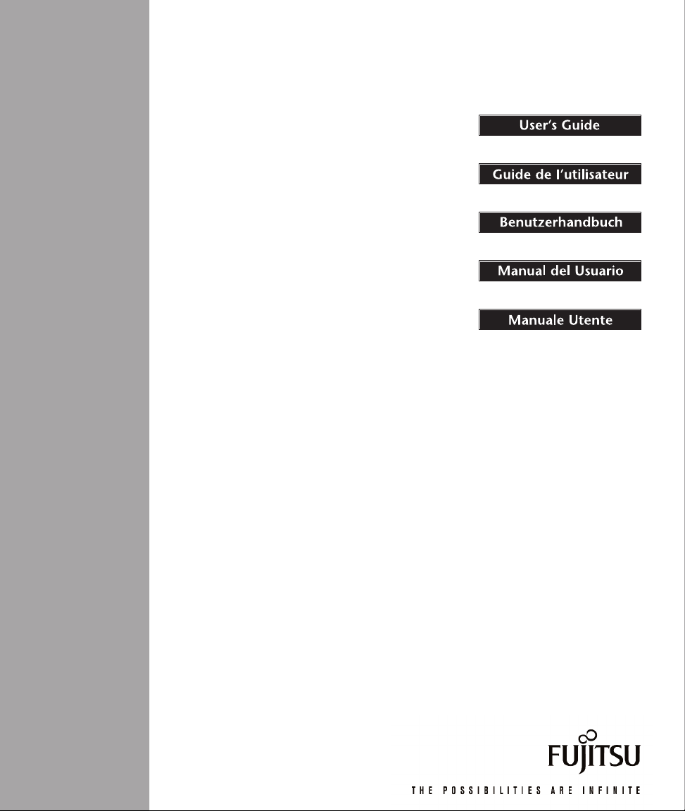
Stylistic 3500 Pe n Tablet Features 1
Features and controls that you use to operate the Stylistic 3500 pen tablet are
described briefly below and illustrated in Fig ures 1-1 and 1-2. Details on using these
features and controls are provided later in this ma nual.
Headphone Jack
Stylus Tether
Attachment Point
Stylus Holder
Air Flow Vents
Modem
Port
IrDA/FIR Port
Microphone Jack
Emergency
Shutoff Button
Power On/Suspend/
Resume Button
PCMCIA
CardBus slot
Floppy
Drive Port
USB (A)
Port
System
Status LEDs
Built-in
Microphone
Infrared
Keyboard
Port
Hotpad Area
Port Replicator
Latch Point
Figure 1-1 Stylistic 3500 Pen Tablet Features (Front/Top View)
Front / Top / Right Features: 1
• System status LEDs: Indicate the operational status of the pen tablet and hard
disk drive, the charge level of the battery, and the status of the hovering mode.
• Stylus: The main pointing device that you use to execute programs and enter
data. A stylus holder is built into the pen tablet to store the stylus when not in use.
• Power On/Suspend/Resume button: Allows you to turn on, suspend, and
resume pen tablet operation in order to optimize battery life.
Serial
Port
DC
Input
Stylistic 3500 Pen Tablet Features 3
Page 10

• Microphone Jack: Allows you to connect an external microphone.
• Headphone Jack: Allows you to connect a set of headphones.
• PCMCIA CardBus slot: Allows you to install PC Cards in the system.
†
• IrDA/FIR port: Provides an infrared interfa c e fo r com mu nication wit h de v ic es
compliant with IrDA Standard Revision 1.1.
• Infrared keyboard port: The infrared port wraps around the front and bottom of
the display, and is used for communicating with a proprietary infrared keyboard
or mouse.
†
• Hotpads: Allows you to change settings for the display, speaker, and mouse by
tapping with the stylus.
• USB port A: Allows you to connect Universal Serial Bus-compliant devices to the
†
pen tablet. USB port B is located on the optional mini-dock or port replicator.
• Modem port: Allows you to connect a standard RJ-11 connector to the pen tablet’s
internal 56 Kbps modem.
Note: The port for the LAN element of the internal LAN/Modem module is available on
the optional mini-dock and/or port replicator.
• DC input connector: Allows you to connect the AC adapter or auto adapter.
†
†
• Emergency shutoff button: Allows you to turn off the pen tablet in the event the
normal shutdo wn pr oced ur e cann ot be perfor med (i.e ., ch oosin g Shut D own fr om
the Windows Start menu). This button should not be used as the normal means of
system shutdown.
• Air flow vents: Provides secondary cooling for processor. (Do not obstruct the
vents.)
• Stylus tether attachment point: Allows you to attach a stylus tether.
†
• Port replicator latch point: Allows you to attach the system to a port replicator or
mini-dock.
†
• Floppy drive port: Allows you to attach a floppy disk drive to the system.
• Serial port: Allows you to connect an external serial device to the Stylistic 3500.
†
These peripherals and accessories are sold separately.
4 Getting Started
†
Page 11
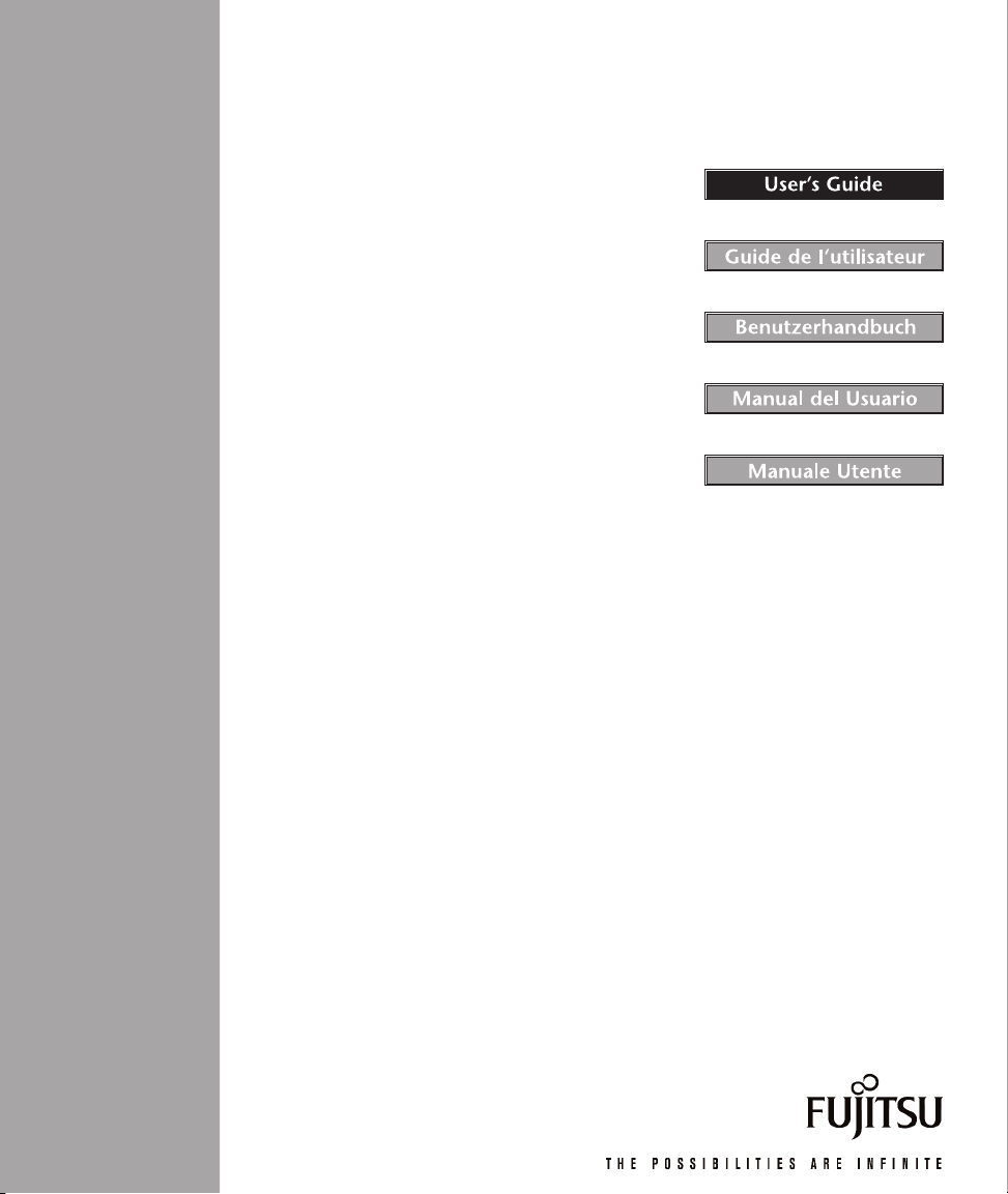
Radio Cover Guide
Memory
Module
Cover
Battery
Release
Button
1
Speaker Hard Disk Drive Cover
System
Interface
Connector
Metal Contacts
(Power and USB)
Air Flow Vents
Battery Pack
Kensington Lock Slot
Port Replicator Latch Point
Battery Latch
Stylus
Figure 1-2 Stylistic 3500 Pen Tablet Features (Rear/Bottom View)
Rear / Bottom / Left Features: 1
• System interface connector: Allows you to connect the Stylistic port replicator,
Stylistic mini-dock, or other approved docking device.
†
• Speaker: Allows you to listen to audio files.
• Metal contacts: Allows you to connect to the Stylistic high-usage dock ing station
with power and USB interface.
†
• Removable battery pack: Can be removed and charged in an opt ional external
†
charger.
1
• Battery latch/battery release button: Used in conjunction to release the
removable battery pack.
• Air flow vents: Provides cooling for processor. (Do not obstruct the vents.)
Stylistic 3500 Pen Tablet Features 5
Page 12

• Port replicator latch point: Allows you to attach the system to a port replicator.
• Memory module cover: Removable cover over the memory modules.
• Radio cover guide: Provides alignment guides and latch points for the third-party
LAN radio solution.
†
• Hard disk drive cover: Covers the hard disk drive module.
• Kensington™ lock slot: Allows you to attach a Kensington
MicroSaver
†
These peripherals and accessories are sold separately.
TM
-compatible security cable.
†
†
6 Getting Started
Page 13
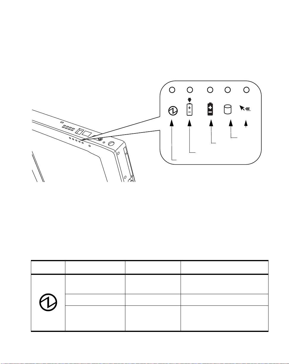
Status Display 1
Icons appear in the Status display indicating the status of system functions such as
system power and battery charge level. The location of icons in the Status display is
shown in Figure 1-3.
Hovering
Battery
Charge/DC In
Power
Figure 1-3 Status Display Icons
HDD
Table 1-1 explains how individual icons are displayed, and describes what the
variations of that display indicate. (If an icon is not displayed, it indicates that the
related system function is off or inactive.
Note: In the following table, a “blinking” LED flashes at the rate of once per second; an
LED that is “blinking, slow” flashes at the rate of one second on, five seconds off.
Table 1-1 System Status Indicators
Icon Mode/State LED State Remarks
Power
• On State
• Idle Mode
• Suspend-to-RAM Green, blinking
• Off State
• Save-to-Disk
Green, continuous
Off
Status Display 7
Page 14
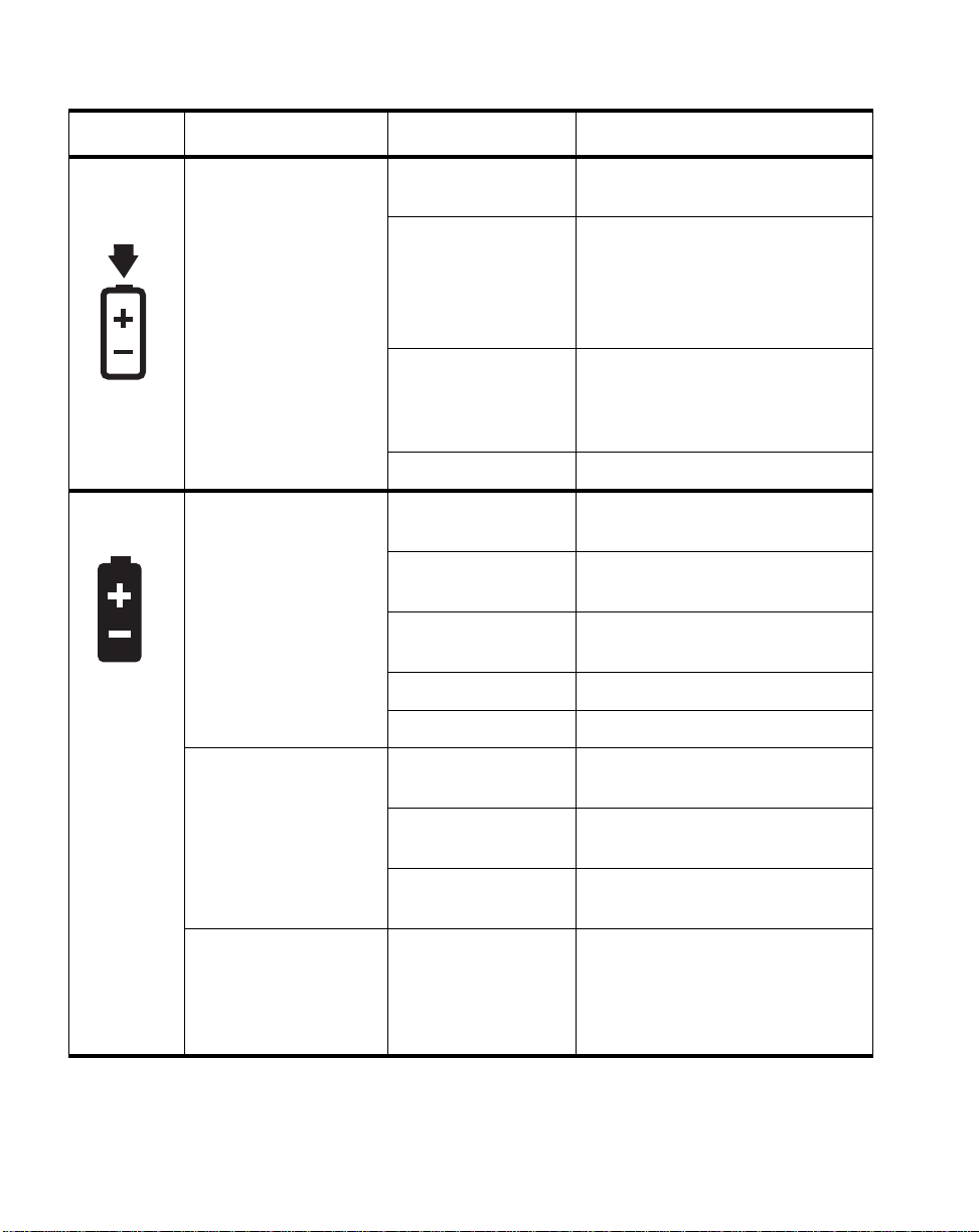
Table 1-1 System Status Indicators
Icon Mode/State LED State Remarks
Charge/
DC Input
Battery • On State
• On State
• Idle Mode
• Suspend-to-RAM
• Save-to-Disk
• Off State
• Idle Mode
• Suspend-to-RAM
with AC adapter
• Save-to-Disk,
with AC adapter
• Off State
Amber AC adapter and battery pack are
available and system is charging.
Green • AC adapter and battery pack
are available and system is not
charging (battery fully charged).
• AC adapter is available but
battery pack is not present.
Amber, blinking AC adapter and battery pack are
available and waiting to charge
(battery pack is out of thermal
range).
Off AC adapter is not available.
Green, continuous Battery pack charge is between
50%-100%
Amber, continuous Battery pack charge is between
13%-49%
Red, continuous Battery pack charge is between
0%-12%
Red, blinking There is a battery error.
Off Battery pack is not installed.
• Suspend-to-RAM,
without AC adapter
• Save-to-Disk,
without AC adapter
• Off State
8 Getting Started
Green, blinking slow Battery pack charge is between
50%-100%.
Amber, blinking slow Battery pack charge is between
13%-49%.
Red, blinking slow Battery pack charge is between
0%-12%.
Off If battery is inserted during power
off, LED blinks amber for 4
seconds to detect battery. Battery
status is displayed for 5 seconds
after that.
Page 15
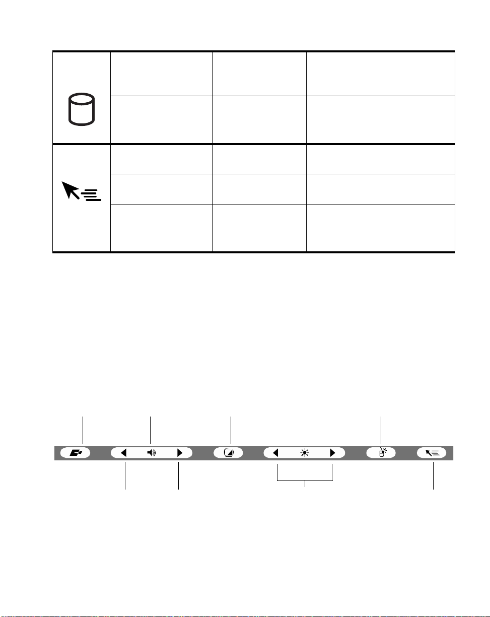
Table 1-1 System Status Indicators
HDD
Access
Hovering • On State
• On State (or
flashing)
• Idle Mode
• Suspend-to-RAM
• Save-to-Disk
• Off State
(Hovering enabled)
• On State
(Hovering disabled)
• Suspend-to-RAM
• Save-to-Disk
• Off State
Green Displayed when hard disk drive is
accessed.
Off Hard disk drive is not being
accessed.
Green Hovering mode is enabled
Off Hovering mode is disabled.
Off
Hotpads 1
Hotpads are stylus-active areas below th e s ystem display that you can use to adjust
the settings of the display and speak e r se ttings while the system is running. Separate
hotpads are available for enabling the right mouse button func tion and the pen
hovering mode.
To use a hotpad, tap directly on it with the stylus. You can also press and hold the
stylus tip against the Volume and Brightness hotpads to automatically repeat the
hotpad function. The location of each hotpad is shown in Figure 1-4.
Programmable Speaker
Icon
On/Off
Volume
Down
Volume
Up
Display
Select
Brightness
(8 levels)
Right
Mouse
Figure 1-4 Hotpads
Hotpads 9
Pen
Hovering
Page 16

A summary of each hotpad’s function is given below:
• Programmable hotpad
This hotpad can be programmed for application-specific functio ns. Contact your
local help desk or reseller if you need assistance using the Programmable hotpad.
• Volume hotpads
These hotpads set the volume of the pen tablet speaker or headphones, if used.
(Note that the internal speaker is disabled when headphones are plugged in.)
• Speaker On/Off hotpad
This hotpad turns the pen tablet speaker or headphones on or off. When you tap
this hotpad to turn on the speaker or headphones, the system beeps.
• Display Select hotpad
Note: This hotpad requires use of an optional VGA Port Replicator that allows
connection of an external display.
This hotpad allows you to choose the pen tablet display screen, an external video
monitor, or both, as the selected system display(s). The pen tablet display screen
appears blank when an external monitor alone is selected.
• Brightness hotpads
Note: These hotpads are not applicable to Stylistic 3500 systems with outdoor
reflective displays.
These hotpads allow you to adjust the display brightness. The brightness can be
adjusted to eight levels.
• Right Mouse hotpad
This icon is used to switch the stylus f unction from left mouse button to right
mouse button emulation. To generate a right mouse button single click, tap on the
hotpad icon once and then tap once on the display. To generate a right mouse
button double click, tap on the hotpad icon once and then double tap o n the
display.
• Pen Hovering hotpad
This hotpad switches the hovering mode on or off; throughout the hovering
mode, the hovering status indicator is lit. Pen Hovering mode provides the user
with better cursor control. When the hovering option is enabled, the cursor can be
positioned over an area of the screen without activating it. This is useful when
you are attempting to read pop-up text associated with an icon, simulating mouse
rollover, selecting a small icon, or beginning a paint session.
10 Getting Started
Page 17
Connectors and Pe riph eral Inter faces 1
Connectors and peripheral interfaces on the Stylistic 3500 pen tablet allow connection
of various devices. Specific locations are illustrated in Figure 1-1 and Figure 1-2.
Table 1-2 provides a description of each peripheral connector on the Stylistic 3500
pen tablet. Each of the illustrated icons is printed on the pen tablet case.
Table 1-2 Peripheral Connectors/Interfaces
Connector/
Peripheral
DC input
connector
Serial port
Floppy drive
port
USB (A) Port Connect Universal Seria l Bus-compliant d evices to the p en
PCMCIA
CardBus slot
Microphone
jack
†
Pen Tablet Icon Purpose
Connect an external power source such as the AC adapter
or auto adapter .
Connect an external serial device to your system.
The floppy disk drive connector uses a special interface
that can be mated on ly with a Fujitsu FMWFD2 floppy disk
drive. Do not attempt to connect any other type of unit to
this connector. Contact your reseller for more information.
tablet. USB (B) port is locat ed on the option al Stylistic 350 0
mini-dock.
Install a Type II PC Card
Connect an external mic rophon e. The in ternal m icrop hone
is disabled when you plug in an external microphone.
Headphone
jack
†
Open the connector door to access these connectors.
Connect stereo headphones or powered external
speakers. The internal speaker is disabled when you plug
in external headphones or speakers.
Connectors and Peripheral Interfaces 11
Page 18

Table 1-2 Peripheral Connectors/Interfaces
Connector/
Peripheral
Pen Tablet Icon Purpose
IrDA/FIR port An infrared transceiver built into the pen tablet allows you
to communicate with other devi ce s that are compliant with
the IrDA Standard Rev. 1.1. Effective range for infrared
communication is about 3 feet, an d within 1 5 degrees off of
center. A clear line-of-sight path must exist between the
IrDA port on the pen tablet and the IrDA tra nscei ver on the
other device.
Modem Connect a telephone line to the optional internal modem
using a standard RJ-11 telephone plug.
High-Usage
Metal Contacts
System
interface port
†
Install the pen tablet in an approved docking device. The
contacts provide DC input and USB interface.
Connect the Stylis tic 3500 port re plicator or o ther approved
docking device. Ref er to the documentati on accompan ying
the docking device for more information.
Infrared
keyboard port
An infrared receiver built into the pen tablet allows you to
communicate with a wireless infrare d keyboard. The
keyboard infrared port works optimally between 10 to 30
cm (approximately 4 in. to 12 in.) from the keyboard
infrared port, loca ted on the bottom edge of the p en tab let .
Ensure that there is a clear line-of-sight path between the
infrared receiver on the pen tablet and the infrared
transmitter on the keyboard.
TM
Kensington
Lock slot
†
Open the connector door to access these connectors.
12 Getting Started
The Kensington MicrosaverTM security slot allows you to
secure the pen tablet using Ken sington-com patible loc king
devices.
Page 19

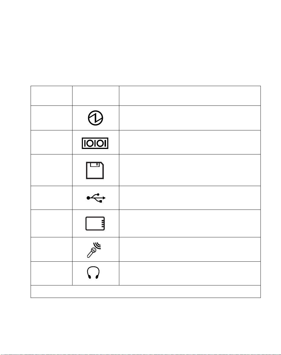
In addition to the connector and interface icons, there are a number of icons that illustrate
component orientation and buttons. These icons are illustrated in Table 1-3.
Table 1-3 Additional System Icons
Icon Description
Battery Indicates the location of the remova bl e
Battery Release Button Indicates the battery release button.
Battery Release Latch, Open Indicates the position of the battery latch
Battery Release Latch, Closed Indicates the position of the battery latch
Power On / Suspend /
Resume Button
Emergency Shutoff Button No icon Powers down the system in the event of
Icon
Illustration
Purpose
battery.
that releases the battery.
that secures the battery.
Indicates the Suspend/Res um e butt on.
system difficulty.
Connectors and Peripheral Interfaces 13
Page 20

14 Getting Started
Page 21

Chapter 2
Using the Stylistic 3500 Pen Tablet
This chapter covers the fundamental concepts, basic system operation and use, and
system functions of the Stylistic 3500 pen tablet. You should familiarize yourself with
this information before you attempt to operate the system.
System States 2
Before you begin using the Stylistic 3500 pen tablet, review the different system states
(or modes) that the pen tablet can use. Being familiar with these system states will
help you determine whether it is appropriate to turn on, resume, suspend, or shut
down the system when you be gin a new session or end you r curre nt session. System
behavior for each system state is described briefly in the following, with each system
state listed in decreasing order of power usage:
• On state
The system is running and the display screen is on.
• Idle state
Some system functions are regulated or turned off to conserve power. The display
screen may be turned off. The system returns to the On state when stylus activity
or other input is detected.
• Suspend-to-RAM mode
System operation is suspended. Most system functions are turned off to conserve
power. Power to memory is on, maintaining data in programs that were running
before system operation was suspended. The system does not respond to the
stylus or other input when in Suspend-to-RAM mode. Refer to the “Resuming
System Operation” section later in this chapter for information on returning the
system to the On state.
• Save-to-Disk mode
System operation is suspended. All system functions are turned off to conserve
power. Active data in programs that were running before suspending system
operation is stored on the hard disk drive. The system does not respond to the
stylus or other input. Refer to the “Resuming System Operation” section later in
this chapter for information on returning the system to the On state.
15
Page 22

• Off state
All system functions are turned off to conserve power. The system does not
respond to the stylus or other input. The system boots at the next system
power-on.
Note: The system consumes the same amount of power whether it is in Save-to-Disk
mode or the Off state.
Your system may be configured to enter some of these states automatically after a
period of inactivity to conserve battery power.
When you use the Stylistic 3500 pen tablet, you can change the current system state
in a number of ways, depending on the current state of the system. To determine the
current system state, observe the Power icon in the Status display. Table 2-1 gives the
different system states represented by the Power icon and describes how you can
change the system state from the current state.
Table 2-1 Changing System States
Power Icon
Appearance
Power icon displayed
continuously
Power icon blinking
Power icon not
displayed
* Information in Table 2-1 is supplied to help you understand which system states your system
can enter from the current system state. Refer to the procedures on starting the system,
shutting down the system, suspending system operation, and resuming system operation
given later in this chapter.
Current State
On State
or
Idle State
Suspend-to-RAM
Off State
or
Save-to-Disk
†
To Change State
To enter the Off state, shut down the system
using the Start menu on your system.
To enter Suspend-to-RAM or Save-to-Disk
state, suspend system operation using either
a hardware or software suspend.
†
To enter the On sta te, resume system
operation by pressing the Suspend/Resume
button.
To enter the Off state, resume system by
pressing the Suspend/Resume button, then
shut down your system.
To enter the On state, start your system, or
resume system operation by pressing the
Suspend/Resume button.
*
†
†
Your system may be configured to use either Suspend-to-RAM mode or Save-to-Disk mode.
16 Using the Stylistic 3500 Pen Tablet
Page 23

Powering Up the Pen Tablet 2
Follow the procedure below to start the Stylistic 3500 pen tablet. Before you begin,
confirm that the system is in the Off state. To do so, observe the Status display. If the
Power icon is not visible in the Status display, th e system is in the Off state or in
Save-to-Disk mode and it is safe to perform this procedure. If the Power icon is
visible (either blinking or on continuously), do not perform this procedure. See
“System States” earlier in this chapter for details on operational modes represented
by the Power icon.
1. Press the Power On/Suspend/Resume button to start the system.
2. Ensure that the battery pack in your pen tablet is sufficiently charged, or connect
an external power source such as the AC adapter or auto adapter to your pen
tablet. See “Status Display” in Chapter 1 to determine the percentage of charge
represented by the Battery Gauge icon in the Status display.
After performing system initialization, the system starts the operating system
installed on the hard disk drive. Once the operating system is running, you can use
the system.
Shutting Down the System 2
Follow these steps to shut down and turn off your system:
1. If system operation has been suspended, resume system operation. See
“Resuming System Operation” later in this chapter for details.
2. Save your work and close all running programs.
3. Choose Sh ut Down from the Windows (98, NT Workstation, or 2000) St art menu.
4. Carry out the Shut Down command.
The system is now in the Off state.
Powering Up the Pen Tablet 17
Page 24

Suspending Syste m Oper ation 2
The Stylistic 3500 pen tablet allows you to suspend the system operation without
closing programs or exiting the operating system. Use this feature to conserve battery
power when a system shutdown is not practical or wh en the battery needs to be
changed.
To suspend system operation:
1. Press the Suspend/Resume button, or carry out the Standby command from your
operating system or power management program. (If your system is configured
to suspend operation using Save-to-Disk mode, which is explained later in this
procedure, a message is displayed while data is saved to your hard disk.)
Caution
If you are replacing the battery pack, wait until system operation is
suspended and the power icon is flashing before you remove the battery
pack. Failure to do so could result in loss of your unsaved data.
The Power icon either flashes (Suspend-to-RA M) or is not displayed
(Save-to-Disk) when system operation is suspended, depending on how your
system is configured. At this point, programs that were running are stopped,
active data is saved, and the system enters one of two different low-power states,
or suspend modes, as explained in the following paragraphs.
2. Observe the Power icon in the Status display to determine which suspend mode
your system is using.
• Power icon is blinking: Suspend-to-RAM mode
In this mode, active data is saved by maintaining power to RAM while most
other system components are powered off. The Battery Gauge icon in the
Status display indicates the battery charge level.
• Power icon is not displayed: Save-to-Disk mode
In this mode, active data is stored on the hard disk drive and power usag e is
reduced to the same level used in the Off state. When the system is in
Save-to-Disk mode, the Battery Gauge icon is not visible in the Status display.
In this mode, there is no danger of losing data if battery power is lost.
If you have successfully performed this procedure, system operation is now
suspended. Refer to “Resuming System Operation” later in this chapter to resume
18 Using the Stylistic 3500 Pen Tablet
Page 25

system operation. Also, note the following with regard to suspending system
operation:
• You can remove the battery pack while the system is in Suspend-to-RAM or
Save-to-Disk modes in order to install a charged battery pack. To prevent losing
unsaved data, wait until system operation has suspended before you remove the
battery pack.
• Y our system may be configured to suspend operation automatically after a period
of inactivity.
• Your system may be configured to enter Save-to-Disk mode automatica lly after a
period of time in Suspend-to-RAM mode.
• The system uses a small amount of battery power when in Suspend-to-RAM
mode. Eventually, the ba ttery will become fully discharged.
Note: If you will not be using the system for an extended period of time, shut down the
system rather than using Suspend-to-RAM mode.
• If the battery pack charge drops to a Low-Battery Warning level wh ile the system
is running, the system will beep periodically. If this occurs, suspend system
operation, shut down the system, or attach an external power source, such as the
AC adapter, to the pen tablet.
• If the battery charge drops to a Critically Low level while the system is running,
the system is forced into a pre-selected mode (Suspend-to-RAM or Save-to-Disk).
If this occurs, you must either install a charged battery pack, or connect an
appropriate external power source such as the AC adapter before you can resume
system operation. (If the battery charge drops to a Critically Low level wh ile the
system is in Suspend-to-RAM mode, the system stays in Suspend-to-RAM mode
until power is restored or totally dissipated.)
• Suspending system operation interrupts data communications; therefore, some
programs may block the system from suspending to prevent an interruption.
• The suspend action of the Suspend/Resume button may be disabled to prevent
accidental interruption. If this is the case, pressing the Suspend/Resume button
will not suspend system operation as described her e. (In this case, suspend mode
can only be achieved using the system softwa re). Contact yo ur local help desk or
reseller if your system configuration is not suitable.
• If your system is equipped with a PC Card that allows you to connect to a wired
or wireless network, you may be logged off the network after a period of
inactivity while system operation is suspended. Contact your network
administrator or help desk for details on lo g-off parameters for your network.
Suspending System Operatio n 19
Page 26

Resuming System Operation 2
To resume system operation, (from either Suspend-to-RAM or Save-to-Disk modes),
press the Suspend/Resume button.
• From Suspend-to-RAM mode
Status lights indicate that the system state is changing. It may take up to a minute
before the system returns to the On state and system operation resumes. Note that
the display turns on shortly before the stylus becomes active due to the power-up
sequences observed by the system.
• From Save-to-Disk mode
Active data is read from the hard disk drive, and the system returns to the On
state after a short period of time.
Note that power to several system components must be restored before system
operation resumes. Allow sufficient time for system operation to resume before
attempting to use the system. If your system uses Save-to-Disk mode, it will take
longer to resume operation as compared to using Suspend-to-RAM mode. Time is
needed to read data from the hard disk drive.
• Use the system as you normally would once system operation resumes.
All programs resume at the point where execution stopped when system operation
was suspended.
Using the stylus 2
You can use the Stylistic 3500 stylus (also called a “pen”) to generate and create
electronic “ink”, to select items, and to navigate through programs on the pen tablet.
The stylus can be used like a two button mouse when used in conjunction with the
right-mouse button hotpad. Program s which support handwriting recognition allow
you to write characters directly on the screen with the stylus and then transla te your
printed text into keyboard-style input.
Caution
• Ensure that a screen protector is installed on the pen tablet
screen before you use the stylus. The warranty does not
cover a screen that is scratched as a result of not using a
screen protector.
• Use only the stylus provided with you r pen ta blet. Do n ot use
substitutes that were not designed for the Stylistic 3500.
20 Using the Stylistic 3500 Pen Tablet
Page 27

To toggle between using the stylus for inking and using it as a mouse, click on the
small pen icon in the system tray at the bottom right of the screen.
Here are some hints on using the stylus simi lar to a tw o-button mouse on a desktop
system:
• To select an object, tap the mouse tip on the object once. This functions like a
mouse button click with the left mouse butto n.
• To “double-click” an object, tap twice on the object quickly.
• To generate a “right mouse button single-click”, tap on the hotpad icon once and
then tap once on the display. To generate a “right mouse button double click”,
tap on the hotpad icon once and then double tap on the display.
• To move, or “drag”, an object on the screen, place the stylus tip directly over the
object, then as you hold the stylus tip against the screen, move the stylus.
Calibrating the stylus 2
Calibration of the stylus adjusts the cursor posit ion on the screen relative to the
position of the stylus tip. You calibrate the stylus to adjust the distance error between
where the stylus actually touches the screen and where the system “thinks” the
stylus is touching. If the event you wish to invoke is not displayed under the stylus
tip when you use the stylus, you should calibrate the stylus.
Stylus calibration may be required due to the follo wing situations:
• The stylus is being used for the first time.
• The previous user of the Stylistic 3500 pen tablet writes with the opposite hand or
at a different stylus angle.
• The system has been in use for some time and the stylus has not been recalibrated.
• The original system image has been restored.
Using the stylus 21
Page 28

To Calibrate the Stylus 2
1. Open the Control Panel from the Start|Settings menu, and double-tap the Pen
Configuration icon. Select the Calibration property sheet, then click on Pen
Calibration.
2. Position the Stylistic 3500 pen tablet as you normally would during use. Be sure to
hold the stylus at the angle that you regularly use. Touch the screen only with the
stylus tip; inadvertently touching the screen with your finger or hand during the
calibration process, may result in faulty calibration.
3. Perform the calibration steps according to the instructions on the screen. The
calibration utility displays a cross-hair symbol in the middle and corners of the
screen, one corner at a time. Hold the stylus as you normally would while using
the system and, as accurately as possible, tap the center of each cro sshair as it is
displayed.
A dialog box is displayed after you tap the last of the four cross-hair symbols. Tap
the screen within 20 seconds if you wish to save your new calibration settings. If
you don’t tap the screen within 20 seconds, the default calibration settings will be
used.
4. When the Verify New Pen Calibration Settings window appears, choose one of
the following steps.
• If you are satisfied that you tapped the cross-hairs accurately, tap Yes. The
taps that you performed in step 3 are then used to calibrate the screen.
• If you do not want to use the new calibration, tap No.
• If you want to enter a new calibration, tap Recalibrate. The calibration
instructions reappear.
If you have successfully performed the procedure above, the stylus is now
recalibrated, and you can use the system as you normally would.
Replacing the Stylus 2
With use, the stylus tip may become worn or may pick up foreign particles that can
scratch the screen. A damaged or worn tip may not move freely, causing
unpredictable results when using the stylus. If your stylus exhibits these problems,
contact your reseller to purchase replacements.
22 Using the Stylistic 3500 Pen Tablet
Page 29

Charging the Ba tte ry Pack 2
The Stylistic 3500 battery pack can be charged while it is installed in the pen tablet.
To do so:
1. Connect a DC power source, such as the AC adapter, to the DC input connector
on the pen tablet. The DC Input icon appears in the Status display. If the battery
pack charge level is below 90%, the battery pack begins charging and the
Charging icon appears in the Status display. If the battery pack charge is 90% or
higher when you connect DC power, the battery pack will not charge, preventing
overcharging the battery pack.
2. Look at the Battery Gauge icon in the Status display to determine the percent of
charge in the battery pack. See “Status Display” in Chapter 1 of this manual for a
description of the Battery Gauge icon.
As long as DC power remains connected to th e pen tabl et, the charging process
continues until the battery pack charge reaches 100%. Charge times shown in Table
2-2 are for a fully discharged battery pack charging both while the pen tablet is and is
not in use.
Table 2-2 Battery Pack Charging Time
Battery Pack Charge
Level Reached
90% 3 hours 6 hours*
100% 4 hours 8 hours*
Approximate Charge Time
(tablet not in use)
Approximate Charge Time
(tablet in use)
* Depends upon the applications in use.
Also note the following with respect to charging the battery pack:
• You can use the system, suspend system operation, or shut down and turn off the
system without interrupting the charging process; however, using the system
while the battery pack is charging will cause the battery pack to charge at a slower
rate, as noted in Table 2-2.
• As noted in the procedure above, the system will not begin charging the battery
pack if the battery pack charge level is 90% or higher when the syst em is initially
connected to external DC power. (This prevents the battery pack from being
overcharged.)
Charging the Battery Pack 23
Page 30

• The Stylistic 3500 battery pack uses Lithium ion battery cells which have no
“memory effect.” You do not need to discharge the battery pack before you begin
charging.
Removing and Instal ling the Batt ery Pack 2
The battery pack can be removed from the pen tablet and swapped with a charged
battery pack. The battery pack can then be charged in an external charger if one is
available. To remove the battery pack from the pen tablet:
1. Choose one of the following:
• If a charged battery pack is available, you can suspend system operation. A
built-in “bridge” battery will maintain the system in Suspend-to-RAM mode
for about 5 minutes while the battery pack is removed; this allows time for
replacement with a charged battery pack.
• If a charged battery pack is not available, save your work and close all
running programs, then shut down the system or Save-to-Disk.
• Plug in an external DC power source.
2. Press and hold the battery release button. (See Figure 2-1.)
3. While holding the button, slide the battery release latch in the direction indicated
in Figure 2-1. The edge of the battery pack lifts away from the surface of the
system.
4. Remove the battery pack from the pen tablet.
If you are using an external battery charger, refer to the instructions provided with
the battery charger.
To install the battery pack:
1. Orient the battery such that the battery connector is positioned over the connector
in the empty battery pack tray. Lay the battery pack into the tray and press it
firmly into the tray until it is seated. When it is properly seated, the battery release
latch should move towards the battery release button.
2. When the battery is firmly seated, press the battery release latch towards the
battery release button until the release button pops up to the level of the system.
Once the battery pack is installed, you can resume system operation or start your
system and use the system normally.
24 Using the Stylistic 3500 Pen Tablet
Page 31

Battery Release Button Battery Release Latch
Battery Cover
Figure 2-1 Removing the Battery Pack
Tips for Conserving Battery Power 2
You can extend the charge life of your battery pack by conserving battery power.
(Your results may vary depending on your applicatio n and how the system is
configured.) Here are some suggestions to help you conserve battery power:
• Use an external power source such as the AC adapter to power the system when
possible.
• Suspend system operation if you know that you won’t be using the system for a
while.
• Shut down the system if you won’t be using the system for an extended period of
time.
• Use power management (accessible through the BIOS setup) to help you conserve
power automatically. Contact your reseller before modifying the BIOS.
* Battery life is dependent upon the operating system, power settings, and
applications in use.
Tips for Conserving Battery Power 25
Page 32

Operation of the Bridge Batte ry
When installed in the pen tablet, the battery pack provides power to some system
components—even when the system is in the Off state. When the battery pack is
removed, power is supplied to these components by a “bridge” battery that is built
into the pen tablet.
The bridge battery is not designed for long-term operation. To maintain the bridge
battery properly, observe the following measures:
Note: The system arrives with the bridge bat tery in a discharged state.
• To prevent draining the bridge battery, always store the pen tablet with a charged
battery pack installed.
• If the bridge battery becomes drained, it takes approximately 11 hours for it to be
fully recharged.
• The bridge battery charges when the AC Adapter is connected and the system is
in On or Off states or Suspend mode. It charges from the battery only when the
system is in the On state.
Modem Connection 2
Note: • The internal 56 Kbps LAN/modem module installed in the Stylistic 3500 pen
tablet has actual maximum transfer rates of 53 Kbps (receive), 33.6 Kbps (send),
and 14.4 Kbps (fax). Download rates are limited to 53 Kbps in the United States
due to FCC restrict ions.
• The LAN portion of the internal LAN/modem module can only be used when the
system is used with th e o ptional mini-dock o r port replicator; there is no LAN
port on the system itse l f .
The Stylistic 3500 pen tablet is designed to accept a standard RJ-11 telephone plug.
Connect the plug to the modem jack located on the top of the pen tablet, to the left of
the IrDA port (reference Figure 1-1). The telephone plug can be installed whether or
not the pen tablet has power applied.
If you need assistance configuring the Stylistic 3500 pen tablet modem or LAN,
contact your local help desk or your reseller.
26 Using the Stylistic 3500 Pen Tablet
Page 33

PC Card Slot 2
The Stylistic 3500 pen tablet PC Card slot allows you to install a Type II PCMCIA
CardBus card.
To install a PC card, position the side with the arrow facing up (i.e., when looking at
the tablet’s display side, the arrow on the card should be visible.) Slide the card into
the PC Card slot, and press it firmly to ensure proper seating.
To install a radio PC card, refer to the documentation accompanying your radio PC
Card. The Antenna Cover Kit (FMW42RC1) is designed to cover the radio antenna to
protect it from damage.
If you need assistance installing a PC Card in the Stylistic 3500 pen tablet, contact
your corporate help desk or your reseller.
PC Card Slot 27
Page 34

28 Using the Stylistic 3500 Pen Tablet
Page 35

Chapter 3
Care and Maintenance
This chapter gives you pointers on how to care for and maintain your Stylistic 3500
pen tablet.
Protecting the Di splay S creen 3
The Stylistic 3500 pen tablet is designed to provide you with years of service. Using a
screen protector will help ensure that the screen remains as clear as possible. When
installed, the screen protector becomes a durable, replaceable writing surface that
protects the display screen from abrasion.
To obtain additional screen protectors use Fujitsu part number FMWSP10 (12-pack)
when ordering. Additional information about installation is inclu ded with the screen
protectors.
Caution
During normal use of the pen tablet, small particles from the
environment can become embedded in the stylus tip and
scratch the screen. To prevent scratching the screen, ensure
that a screen protector is installed before using your pen
tablet. The warranty do es n ot cover a sc reen th at is sc ratche d
as a result of not using a screen protector.
To install a new screen protector on your pen tablet:
1. If a screen protector is already installed on the display screen, remove it before
installing the new screen protector.
The screen protector is held onto the display screen surface by a thin strip of
adhesive around the edges. A notch in one corner of the screen protector allows
you to slide your fingernail under the screen protector for easy removal.
2. Clean the display by wiping the screen surface gently using a soft cotton cloth
dampened with isopropyl alcohol . Ensur e tha t all r esidue ha s been r emo ved fr om
the screen before applying a new screen protector.
29
Page 36

Caution
The Stylistic 3500 pen tablet is not waterproof. Do not pour
liquids on the system or wash it with a heavily soaked cloth.
3. Remove the protective coating from the adhesive side of the screen protector first.
4. Apply the screen protector to the display screen surface. When doing so, orient
the screen protector with the adhesive side of the screen protector facing the
display screen and the notched corner of the screen protector toward the lower
left corner of the display screen.
5. Apply pressure to the screen protector with your finger using a continuous
wiping motion along the edges. The adhesive sets completely within 48 hours. To
ensure a good seal between the screen protector and the display, do not lift the
screen protector from the display once it has been applied.
6. Remove the protective plastic cover from the face of the screen protector.
7. Clean any residue left behind by the protective coating from the exposed surface
of the screen protector by wiping gently with a soft cotton cloth dampened with
isopropyl alcohol. Wipe the screen protector with a soft dry cloth to remove any
low-tack adhesive; this will help prevent the stylus tip from squeaking.
The screen protector is now installed.
Storing the Styl isti c 3500 Pe n Tablet 3
Caution
Do not store your Stylistic 3500 with the screen side down,
otherwise damage to the display may occur.
Store the Stylistic 3500 pen tablet in the Off state with a fully charged battery pack
installed. You can store the pen tablet in the Off state for about 30 days with a fully
charged battery pack installed. After this period, the ba ttery pack should be
recharged or replaced with a charged battery pack.
If you intend to store the pen tablet for a longer period of time, the small battery that
maintains system time may need to be replaced. Replacement of the clock battery
should only be performed by authorized technicians.
30 Care and Maintenance
Page 37

Avoidi ng Overh eatin g 3
The Stylistic 3500 pen tablet monitors its internal temperature. As the internal
temperature approaches the tolerable limits of heat-sensitive components, system
functions are automatically limited or turned off to prevent damage.
To avoid overheating the pen tablet, do not obstruct the air vents on the top and
bottom edges of the pen tablet.
Cleaning the Disp lay Screen 3
To clean the pen tablet display screen, wipe the screen surface gently using a soft
cotton cloth slightly dampened with water or isopropyl alcohol.
Caution
The Stylistic 3500 pen tablet is not waterproof. Do not pour
liquids on the pen tablet or wash the pen tablet with a heavily
soaked cloth.
Avoiding Ov erheating 31
Page 38

Troubleshooting 3
Solutions to some common problems are described in the following sections. If you
are experiencing a problem with your Stylistic 3500 pen tablet tha t you cannot solve
by taking the actions described, contact your local help desk or your reseller for
further assistance.
System Will Not Resume Operation 3
If the system will not resume operation after system operation has been suspended,
check the following possible causes:
• The battery pack may either be defective, or discharged to the critically low level.
When the battery pack reaches the critically low level, the system is forced into
Suspend-to-RAM mode to avoid a total system power failure. To correct this
problem, either connect an external power supply (such as the AC adapter), or
install a charged battery pack in the pen tablet.
• The system may be at the critical thermal limit. To avoid damage to heat-sensitive
components, the system enters Suspend-to-RAM mode when it gets too hot.
System operation cannot be resumed until the pen tablet cools off to a tolerable
temperature. Move the pen tablet to a cooler location.
Display Screen Is Blank or Difficult to Read 3
If the display screen on your Stylistic 3500 pen tablet appears blank or is unreadable,
confirm that the system is running (th e P ower icon is displayed continuously on the
Status display), and check the following:
• The system brightness may be set too low, causing the screen to appear too dark.
Use the brightness hotpad to adjust the screen brightness.
• An external monitor may be selected. Tap on the Display Select hotpad to
determine whether the pen tablet display screen is selected.
• The video timeout may have expired. Tap on the display screen to reactivate the
display. Note that this is a normal, power-saving feature.
Cursor Is Not Tracking Stylus 3
If the cursor on the screen appears to be misaligned with the stylus or is not
accurately tracking the stylus, calibrate the stylus. See “Calibrating the Stylus” in
Chapter 2 for details.
32 Care and Maintenance
Page 39

Infrared Data T ransf er Is No t Working 3
If you are experiencing problems transferring data over the system’s infrared
interface, note the following:
• Can the IrDA port on the pen tablet “see” the IrDA port on the other device? A
direct line-of-sight path must exist between the IrDA port on the pen tablet and
the IrDA port on the other device.
• The distance between the two devices must not be more than approximately 3
feet.
• The viewing angle from the IrDA port on the pen tablet must not be more than 15
degrees from a center line between the IrDA port on the pen tablet and the IrDA
port on the other device.
• The device with which you are trying to communicate must be compliant with the
IrDA Stand ard Revision 1.1 (or 1.0).
Pen Tablet Is Not Responding to the Stylus 3
If your pen tablet is not responding to the stylus, connect an external keyboard to the
system to see if it responds to keyboard commands. If the system doesn’t respond to
the keyboard, the application or system may have crashed, and it may be necessary
to reset the system. If the system responds to the keyboard but not to the stylus,
contact your local help desk or reseller for further assistance.
Audio Volume Too Low 3
If the audio volume on your pen tablet speaker or external headphones is too low,
check the following:
• Ensure that the speaker (or headphone output if using headphones) is enabled. T o
do so, tap the Speaker Mute hotpad. The system beeps when the speaker or
headphone output is turned on using the hotpad.
• Ensure that the volume level set with the Volume hotpads is set to an audible
level.
• Ensure that the mute box in the system volume control (accessible from the
system tray) is not set.
• Ensure that any volume control in your audio software is set to an audible level.
Troubleshooting 33
Page 40

Configuring P eri ph er al s In ter fa c es 3
Certain peripheral devices can be disabled during the BIOS Setup. If the peripheral
interface you want to use does not appear to be working with your peripheral device,
ensure that it is enabled in the BIOS. Contact your local help desk or reseller if you
need assistance using BIOS Setup.
34 Care and Maintenance
Page 41

Appendix A
Agency Notic es
UL Notices 3
Cautions
• Changes or modifications not expressly approved by Fujitsu PC Corporation could
void this user’s authority to operate the equipment.
• This unit requires an AC Adapter to operate. Use only UL Listed “Class 2” adapters
with an output rating of 16 Vdc, 3.36 A. AC Adapter output polarity:
+
• To reduce the risk of fire, use only No. 26 or larger telecommunication line cord.
• To charge the battery pack FMW45BP1 externally, use only a Stylistic external battery
charger model FMW42BC1.
• There is a danger of explosion if the Lithium (CMOS) battery is incorrectly replaced.
Replace only with the same or equivalent type recommended by the manufacturer.
Dispose of used batteries according to manufacturer's instruction.
Warning
(For Authorized Repair Technicians only:)
• For continued protection against the risk of fire, replace fuse only with the same
type and rating of fuse..
FCC Notices 3
This equipment has been tested and found to comply with the limits for a Class B
digital device, pursuant to Part 15 of the FCC rules.
Changes or modifications not expressly approved by Fujitsu PC Corporation, could
void the user’s authority to operate the equipment.
Agency Notices 35
Page 42

Notice to Users of Radios and Television 3
These limits are designed to provide reasonable protection against harmful
interference in a residential installatio n. This equipment generates, uses, and can
radiate radio frequency energy and, if not installed and used in accordance with the
instructions, may cause harmful interferen ce to radio communications. However,
there is no guarantee that interference will not occur in a particular installation. If the
equipment does cause harmful interference to radio or television reception, which
can be determined by turning the equipment off and on, the user is encouraged to try
to correct the interference by one or more of the following measures:
• Reorient or relocate the receiving antenna.
• Increase the separation between the equipment and receiver.
• Connect the equipment into an outlet that is on a different circuit than the
receiver.
• Consult the dealer or an experienced radio/TV technician for help.
Shielded interconnect cables must be employed with this equipment to ensure
compliance with the pertinent RF emissions limits governing this device.
Notice to Users of the US Telephone Network 3
The Stylistic 3500 pen tablet is supplied with an internal modem which complies
with Part 68 of the FCC rules. On the pen tablet is a label that contains the FCC
Registration Number and Ringer Equivalence Number (REN) of this system, along
with other information. If requested, users must provide their telephone company
with the following info rmation:
• The telephone number to which the pen tablet is connected
• The Ringer Equivalence Number (REN) for this equipment
• The information that the system requires a standard modular jack type USOC
RJ-11C which is FCC Part 68-compliant
• The FCC Registration Number
This equipment is designed to be connected to the telephone network or premises
wiring using a standard mod ular jack type USOC RJ-11C which is FCC Part
68-compliant.
The REN is used to determine the number of devices you may connect to your
telephone line and still have all those devices ring when your number is called.Too
many devices on one line may result in failure to ring in response to an incoming call.
36 Appendix
Page 43

In most, but not all, areas, the sum of all of the devices should not exceed five (5). To
be certain of the number of devices you may connect to your line, as determined by
the RENs, contact your local telephone company .
If this equipment causes harm to the telephone network, your telephone company
may discontinue your service temporarily. If possible, they will notify you in
advance. If advance notice is not practical, they will notify you as soon as possible.
You will also be advised of your right to f ile a complaint with the FCC.
This fax modem also complies with fax branding requirements per FCC Part 68.
If you experience trouble with this equipment, please contact your support
representative.
Your telephone company will probably ask you to disconnect this equipment from
the telephone network until the problem is corrected and you are sure that the
equipment is not malfunctioning.
This equipment may not be used on coin service telephones provided by your
telephone company. Connection to party lines is subject to state tariffs. Contact your
state’s public utility commission , p ublic services commission, or corporation
commission for more information.
FCC rules prohibit the use of non-hearing aid compatible telephones in the following
locations or applications:
• All public or semipublic coin-operated or credit card telephones.
• Elevators, highways, tunnels, (automobile, subway, railroad, or pedestrian) where
a person with impaired hearing might be isolated in an emergency.
• Places where telephones are specifically installed to alert emergency authorities
such as fire, police, or medical assistance personnel.
• Hospital rooms, residential health care facilities, convalescent homes, and prisons.
• Workstations for the hearing impaired.
• Hotel, motel, or apartment lobbies.
• Stores where telephones are used by patrons to order merchandise.
• Public transportation terminals where telephones are used to call taxis or to
reserve lodging or rental cars.
• In hotel and motel rooms at least ten percent of the rooms must contain hearing
aid compatible telephones which will be provided to hearing impaired customers
on request.
Agency Notices 37
Page 44

DOC (Industry Canada) Compli ance Notice s 3
This digital apparatus does not exceed the Class B limits for radio noise emissions
from digital apparatus as set forth in the radio interference regulations of the
Canadian Department of Communications.
Le présent appareil numérique n’émet pas de bruits radioélectriques dépassant les
limites applicables aux appareils numériques de classe B prescrites dans le règlement
sur le brouillage radioélectrique édicté par le Ministère des Communications du
Canada.
Notice to Users of Radios and Television 3
This Class B digital apparatus meets all requirements of the Canadian
Interference-Causing Equipment regulations.
Cet appareil numérique de la classe B respecte toutes les exigences du règlement sur
le matériel brouilleur du Canada.
Notice to Users of th e C a na dian Telephone Network 3
The Canadian Industry Canada label identifies certified equipment. This certification
means that the equipment meets certain telecommunications network protective,
operational, and safety requirements. The Department does not guarantee the
equipment will operate to the user’s satisfaction.
Repairs to telecommunication equipment should be made by a Canadian authorized
maintenance facility. Any repairs or alterations not expressly approved by Fujitsu PC
Corporation or any equipment failures may give the telecommunication s company
cause to request the user to disconnect the equipment from the telephone line.
The connecting arrangement code for this equipment is CA11A.
The Load Number assigned to each telephone terminal device denotes the
percentage of the total load to be connected to a telephone loop or circuit to be used
by the device to prevent overloading. The termination on a loop may consist of any
combination of devices such that the total of the load numbers of all devices does not
exceed 100.
38 Appendix
Page 45

Caution
For safety, users should ensure that the electrical ground of the
power utility, the telephone lines, and the metallic water pipes are
connected together. Users should not attempt to make such
connections themselves but should contact the appropriate electric
inspection authority or electrician. This may be particularly
important in rural areas.
Avis Aux Utilisateurs Du Réseau Téléphonique Canadien 3
L’étiquette canadienne Industrie Canada identifie l’équipement certifié. Cette
certification signifie que l’équipement satisfait certaines normes de protection,
d’exploitation et de sécurité des réseaux de télécommunications. Le département ne
garantit pas le fonctionnement de l’équipement à la satisfaction de l’utilisateur.
Le Stylistic 3500 possede un modem interne conforme aux normes de certification
d’Industrie Canada pour protéger les réseaux de t éléc ommu nic at ions et s ati sfai re aux
normes de sécurité. Avant de connecter cet équipement à une ligne téléphonique,
l’utilisateur doit vérifier s’il est permis de connecter cet équipement aux installations
de télécommunications locales. L’utilisateur est averti que même la conformité aux
normes de certification ne peut dans certains cas empêcher la dégradation du service.
Les réparations de l’équipement de télécommunications doivent être effectuées par
un service de maintenance agréé au Canada. Toute réparation ou modification, qui
n’est pas expressement approuvée par Fujitsu PC Corporation, ou toute défaillance
de l’équipement peut entrainer la compagnie de télécommunications à exiger que
l’utlilisateur déconnecte l‘équipement de la ligne téléphonique.
Le code d’arrangement de connexion de cet équipement est CA11A.
Le numéro de charge assigné à chaque terminal téléphonique indique le pourcentage
de la charge totale pouvant être connecté à une boucle ou à un circuit téléphonique,
utilisé par ce périphérique afin de prévenir toute surcharge. La terminaison d’une
boucle peut être constituée de n’importe quelle combinaison de périphériques de
sorte que le total de numéros de charge de tous les périphériques n’excède pas 100.
Agency Notices 39
Page 46

Avertissement
Pour assurer la sécurité, les utilisateurs doivent vérifier que la
prise de terre du service d’électricité, les lignes
téléphoniques et les conduites d’eau métalliques sont
connectées ensemble. Les utilisateurs NE doivent PAS tenter
d’établir ces connexions eux-mêmes, mais doivent contacter
les service s d’inspection d’installations électriques
appropriés ou un électricien. Ceci peut être particulièrement
important en régions rurales.
40 Appendix
Page 47

Appendix B
Stylistic 3500 Hardware Specifications
The following table provides general hardware specifications of the Stylistic 3500 by
category.
Stylistic 3500 Specifications
Physical Specifications 3
Dimensions 11” w x 8.5” d x 1.1” h (280mm x 215mm x 27.4mm)
Weight 3.2 lbs. (1.45 Kg)
Processing Specifications 3
CPU Intel Celeron 500MHz, 1.1V
Chip set Intel 440MX - 100
Processor Speed 500 MHz
Memory/Storage Specifications 3
Main RAM 64MB, 128MB, and 256MB module con figu rati on s av ail abl e,
with a system maximum of 256MB.
L1 cache (CPU) 32 KB on die
L2 cache 128 KB on die
BIOS ROM
Hard disk drive • 2.5” HDD
512 KB (flash ROM upgradeable)
• 15GB IDE HDD
• Ultra DMA
• Shock-mounted
Stylistic 3500 Hardware Specifications 41
Page 48

Stylistic 3500 Specifications (Continued)
Input/Output Specifications 3
Display • Indoor Color LCD
Transmissive
10.4” TFT XGA (1024 x 768)
256K colors
Brightness: 8 levels
• Indoor/Outdoor Color LCD
Transmissive
10.4” TFT SVGA (800 x 600)
256K colors
Brightness: 8 levels
• Outdoor Color LCD
Reflective
10.4” TFT SVGA (800 x 600)
256K colors
VRAM 4MB RAM
Interface Specifications
PC Card Slots • One Type-II
• PCMCIA CardBus version 3.0
Integrated Interfaces • FDD
• RJ-11
• USB
• DC-In
• Serial connector
• Expansion connectors
Infrared IrDA version 1.1 (FIR, 4Mbps)
Audio • Sound Function + AC’97 codec (18-bit stereo codec)
• Internal microphone and speaker
• Microphone and headphone jacks
High-Usage Docking
Contacts
• DC-In
• USB Host
3
42 Appendix
Page 49

Stylistic 3500 Specifications (Continued)
User Controls • Hotpads: programmable, volume, display, brightness,
right button, hovering
• Power On/Suspend/Resume button
• Emergency Shutoff Button (Power Off button)
Status Indicators (LEDs) • Power
• Charge/DC-In
• Battery level
• HDD
• Hovering
Power Specifications 3
Main Battery • 6-cell
• Removable, Lithium ion
• 10.8 V @ 3100 mAh
• Warm-swappable
• Recharge Time:
Suspend/Off: 3 hours (90%), 4 hours (100%)
Operating: 8 hours (100%)
• Life: ~4 hours (Battery life is dependent upon the
operating system, power management, and applications
in use.)
• Suspend Life: Minimum 5 days
Off State: Approximately 30 days
Sub-Battery
Temperature
Humidity
• 6-cell NiMH, 35 mAh
• Life (with system running on sub-battery only):
~5 minutes from full charge
Environmental Specifications 3
o
o
- 40
Operating: 0
Non-operational: -20
C (32o - 104o F)
o
- 60o C (-4o - 140o F)
Operating: 20 - 80% non-condensin g
Non-operating: 20-80% non-condensing
Stylistic 3500 Hardware Specifications 43
Page 50

Emissions
Immunity
Stylistic 3500 Specifications (Continued)
Agency Approval Specifications 3
• EN55022 (CISPR22) Class B
• FCC 15, Class B
• DOC Class B
• EN61000-4-2:1995
• EN61000-4-3:1995
• EN61000-4-4:1995
Safety
Telecom
Operating systems
• UL and cUL Listed, UL 1950
• TuV T-Mark, EN60950
• FCC Part 68
• IC CS03
Additional Specifications 3
Microsoft
Windows 2000
Windows 98, Windows NT 4.0 Workstation,
44 Appendix
Page 51

Appendix C
Digitizer Technology Notice
Additional Display Information 3
The display for your pen tablet incorporates a breakthrough digitizer technology that
dramatically improves outdoor viewability. Compared to traditional outdoor
displays, the new display excels in providing superior visibility in full sunlight, and a
clear, bright picture indoors, in low light conditions, or at night.
This new technology involves the use of a liq uid between the digitizer layers to
minimize light refraction and reduce glare. As a resu lt of this technology, users may
notice the appearance of tiny air bubbles which are caused by changes in pressure
(such as that experienced in an airplane). These tiny bubbles are temporary and do
not affect system performance or usability. The digitizer functions normally when
the air bubbles are present.
The air bubbles are formed when the liquid vaporizes due to pressure change. When
the pen tablet is returned to normal use conditions, the tiny air bubbles are absorbed
back into the liquid after a short amount of time.
If these air bubbles are visually distracting, or if they form a larger bubble, gently rub
the screen with a soft cotton cloth in a circular motion, si milar to cleaning the screen
of fingerprint oil.
Additional Display Information 45
Page 52

46 Digitizer Technology Notice
Page 53

Index
A
air flow vents, 4, 5
antenna cover ki t, 2
audio volume too low, 33
auto adapter, 2
B
battery charger, external, 2
battery gauge, 23
battery gauge ic on, 18
battery icon, 8, 13
battery latch, 5
battery pack, 2
charging, 23
charging times, 23
critically low level, 19
low-battery warn ing, 19
no memory effect, 24
overcharge protection, 23
removing and installing, 24
will not begin charging, 23
battery power
conserving, 25
used in suspend-to-RAM mode, 19
battery release button, 13
battery release latch, 13
bridge battery, 26
brightness, 9
adjusting, 10
brightness hotpads, 10
C
calibrating the stylus, 21
care and maintenance, 29
Charge/DC input icon, 8
charging the batte ry pack, 23
cleaning the display screen, 31
configuring peripherals interface, 34
connectors and peripheral interfaces, 11
conserving battery power, 25
critically low battery level, 19
cursor
not tracking st ylus, 32
D
DC adapter, 2
DC input connector, 11
DC power connector, 4
display
brightness, adjusting, 10
screen is blank, 32
screen, cleaning, 31
display select hotpad, 10
E
Emergency shutoff button, 4
external battery charger, 2
external floppy disk drive, 2
external vid eo monitor, 10, 11
F
FCC, 35
floppy disk drive connector, 11
floppy drive port, 4, 11
folding deskstand, 2
H
hard disk drive access icon, 9
HDD cover, 6
headphone, 4
headphone j ack, 11
high-usage cradle, 2
high-usage m etal contacts, 12
hotpads, 4, 9
brightness, 10
display select, 10
programmable, 10
right mouse, 10
speaker mute, 10
volume, 10
hovering mode icon, 9
Index-1
Page 54

I
icons, 7
idle state, 15
infrared data transfer not working, 33
infrared keyboard, 2
infrared keyboard port, 4, 12
interfaces
connectors and peripherals, 11
IrDA port, 4, 12
power icon, 7, 16
blinking, 16, 18
not displayed, 16
Power On/Suspend/Resume
button, 3
power on/suspend/resume button, 13
power usage, 15
problems, solving, 32
programmable hotpad, 10
protecting the display screen, 29
K
Kensington lock, 6
Kensington lock slot, 12
L
low-battery warn ing, 19
M
memory cover, 6
metal contacts, 5
microphone, 4
microphone jack, 11
mini-dock, 2
Modem
connection, 26
port, 4
modem, 12
O
Off state, 16 , 17
optional, 2
optional accessories, 2
overheating, avoiding, 31
P
PC Card
slot, 4, 27
PC Card slot, 11
peripheral connectors, 11
port replicator, 2
connector, 12
port replicator latch point, 4
portfolio case, 2
R
removable battery pack, 5
resuming system operation, 20, 32
S
Save-to-Disk mode, 15, 18, 20
screen protectors, 2
serial port, 4, 11
shutting down the system, 17
slip case, 2
solving problems, 32
speaker, 5
speaker mute hotpad, 10
status display, 7
battery icon, 8
Charge/DC input icon, 8
hard disk drive access icon, 9
hovering mode icon, 9
power icon, blinking, 16
power icon, system states indicated by, 7,
16
storing the system unit, 30
Stylistic 3500
accessories, 2
care and maintenance, 29
features, 3, 5
items included with, 1
storing, 30
Stylistic 3500 Specifications
additional, 44
agency approval, 44
environmental, 43
input/output, 41, 45
interface, 42
memory/storage , 41, 45
Index-2
Page 55

physical, 41, 45
power, 43
processing, 41, 45
Stylistic stylus, 2
Stylus, 4
stylus
not responding, 33
replacing, 22
tether, 2
tether attachment points, 4
using, 20
suspend mode, determining, 18
Suspend/Resume
disabled, 19
suspending system operation, 18
Suspend-to-RA M, 15
mode, 18, 20
system interface port, 5, 12
system states, 15, 16
Idle state, 15
Off state, 16
On state, 15
Save-to-Disk, 15
Suspend-to-RA M, 15
system status LEDs, 3
system will not resume operation, 32
W
wall-mount cradle, 2
Windows, 1
Windows 2000, 1
Windows NT4.0 Workstation, 1
T
troubleshooting, 32
turning off the system, 17
U
Universal Serial Bus, 4
USB keyboard, 2
USB Port, 4, 11
Using, 15
using the stylus, 20
V
video port, 11
volume hotpads, 10
Index-3
Page 56

 Loading...