

Fujitsu SRS-9912-SP User Manual


Fujitsu NI / 5E Custom
Terminal Intro & Table of Contents
NI / 5E Custom
Terminal Overview
Using the
Terminal
Terminal Set-Up
SRS-9924-ABM
NI / 5E Custom
Terminal Installation
Terminal Accessories
NI / 5E Custom
Appendix
Terminal Testing
NI / 5E Custom
Appendix
Error Messages
Appendix
Ordering National ISDN Lines
USER GUIDE
1
2
3
4
5
6
A
B
C
D
Appendix
5E Custom
Terminal ICI Displays
SRS-9924/9912-SP
AND

Fujitsu NI / 5E Custom Terminal Intro & Table of Contents
1
Fujitsu Network Communications, Inc.
2800 Sumner Blvd., Suite 124
Raleigh, NC 27616
U.S.A.
Part Number P-UG-99VO-A
Revision 1.4
©
Copyright 2000 Fujitsu Network Communications, Inc. All rights reserved.
Printed in the United States of America.
This publication may be replaced by a revised edition. To find out if a revision
exists, or to order copies of publications, write to Fujitsu Network
Communications, Inc., 2800 Sumner Blvd., Suite 124, Raleigh, NC 27616,
or call 1-800-228-ISDN. Please direct all communications to End User Products.
No part of this publication may be reproduced or translated, stored in a
database or retrieval system, or transmitted in any form or by any means,
electronic, mechanical, photocopying, recording, or otherwise, without the
prior written permission of Fujitsu Network Communications, Inc.
The information contained in this document is subject to change without
notice.

2
Fujitsu NI / 5E Custom Terminal Intro & Table of Contents
Warning
This equipment has been tested and found to comply with the limits for a
Class B digital device, pursuant to Part 15 of the FCC rules. These limits are
designed to provide reasonable protection against harmful interference in a
residential installation. This equipment generates, uses, and can radiate
radio frequency energy and, if not installed and used in accordance with
the instructions, may cause harmful interference with radio communications.
However, there is no guarantee that interference will not occur in a particular
installation. If this equipment does cause harmful interference with radio or
television reception, which can be determined by unplugging the equipment
to turn it off, the user is encouraged to try to correct the interference by one
of the following measures:
•
Reorient or relocate the receiving antenna of the affected
receiver.
•
Increase the separation between the equipment and the
affected receiver.
•
Connect the equipment to an outlet on a circuit different from
the one to which the affected receiver is connected.
•
Consult a dealer or experienced radio or television technician
for help.
Changes or modifications not expressly approved by the party responsible
for compliance could void the user’s authority to operate the equipment.
FCC Notice
This telephone is hearing aid compatible.
This equipment complies with Part 68 of the FCC Rules. The FCC Part 68
Label is located on the bottom of the enclosure. This label contains the FCC
Registration Number for this equipment. If requested, this information must
be provided to your telephone company.
FCC Regulations require that connection of this telephone to the telephone
network be made via an FCC registered NT-1 interface device.
Connection to the telephone network should be made via the NT-1 interface
by using standard modular telephone jacks, type RJ-49. The plugs and/or
jacks used must comply with FCC Part 68 Rules.

Fujitsu NI / 5E Custom Terminal Intro & Table of Contents
3
System Port Identification
Facility Interface & Service Order Codes
Mfgrs Port
Identifier
Facilities
Interface Code
Service Order
Code
Network Jack
6.ON RJ-4902IS5ISDN Line
If this telephone equipment causes harm to the telephone network, the
telephone company will notify you in advance that temporary discontinuance
of service may be required. But, if advance notice isn’t practical, the telephone
company will notify the customer as soon as possible. Also, you will be
advised of your right to file a complaint with the FCC if you believe it is
necessary.
The telephone company may make changes in its facilities, equipment,
operations or procedures that could affect the proper functioning of your
equipment. If this occurs, you will be notified in advance in order to make
necessary modifications to maintain uninterrupted service.
Important Safety Information
The Fujitsu ISDN Terminal should be used according with all instructions
and precautions provided in this guide.
•
Read and understand all installation instructions.
•
Install cords where they cannot be a hazard to anyone walking
nearby.
•
Use only a Class 2 power source or communication circuit power
source. If you use a local power supply, use Model AD-3645U.
•
Use only the line cable included with the terminal.
•
Do not use this product near water, for example, near a bathtub,
wash bowl, kitchen sink, laundry tub, in a wet basement, or in a
swimming pool.
•
Avoid using the terminal during an electrical storm. There may
be a remote risk of electrical shock from lightning.
•
Do not use the terminal to report a gas leak in the vicinity of the
leak.
•
Do not overhaul or open this product.
•
Addition and exchanging of hardware options should be
performed by authorized personnel.
•
Use your one-touch numbers for storing emergency numbers.

4
Fujitsu NI / 5E Custom Terminal Intro & Table of Contents
Repairs
Repairs to this equipment can only be made by the manufacturer or its
authorized agents. If this equipment is causing harm to the telephone
network, the telephone company may request that it be unplugged from
the modular outlet until the problem has been corrected. To obtain repair
service or warranty information, contact:
Technical Assistance Center
Fujitsu Network Communications, Inc.
2800 Sumner Blvd., Suite 124
Raleigh, NC 27616
(919) 790-2211 or 1-800-228-4736
Electrical Safety Advisory
We recommend the installation of an AC surge arrestor in the AC outlet to
which this equipment is connected. Telephone companies report that
electrical surges, typically lightning transients, are very destructive to customer
terminal equipment connected to AC power sources.
Preface
This guide provides descriptions and procedures for using Fujitsu’s Digital
Feature Phones (SRS-9924 and SRS-9912-SP), when attached to a switch
supporting ISDN (National ISDN, referred to as NI or 5E Custom versions).
For assistance ordering National ISDN service from your local service provider,
see Appendix C.
The Fujitsu SRS-9924 and SRS-9912-SP are designed to optimize Centrex and
other ISDN voice services.
HOW TO USE THIS GUIDE
This section can help you make the most efficient use of this guide. The
section describes the overall organization, aids to finding information, and
conventions.

Fujitsu NI / 5E Custom Terminal Intro & Table of Contents
5
Conventions and Layout
•
In procedures, the required actions are noted, with the buttons you
press in capital letters, such as HOLD or REDIAL.
•
Other important words, such as messages that appear on the display,
also appear in CAPITAL LETTERS.
•
Some procedures use the following symbol to indicate which buttons
to press.
•
Call Appearance and Directory Number are abbreviated as CA and
DN.
Menus or screen displays appear as text in boxes.
12:05PM FRI JAN 15
UNA L-DIR CLEAR OPTIONS
Actions that pertain to only a specific type of ISDN (either National or
Custom) or to a particular phone system have the following format or
symbols inserted. These symbols appear in the section heading when
the information applies entirely to that system, or they appear adjacent
to a command where only a specific action applies to that system.
5E Custom Only
National ISDN Only
Instructions pertaining to either NI only or 5E Custom only appear in a
shaded area on the page.
For specific instructions for National ISDN, these symbols are used:
<5ESS> ................................... Required for Lucent Systems.
<DMS-100> ............................ Required for Nortel Systems.
<EWSD> ................................. Required for Siemens Systems.
Note: 5ESS, DMS-100, and EWSD are registered trademarks of Lucent,
Nortel, and Siemens Information and Communication Networks
respectively.
Features or instructions that pertain to only a specific terminal have the
following symbols inserted.
ENTER

6
Fujitsu NI / 5E Custom Terminal Intro & Table of Contents
Softkeys
The softkeys are the four keys located just below the display.
1234
Menu
OPTIONSCLEARL-DIRUNA
12:05PM FRI JAN 15
Standard Softkey Layout
ENTER NEXT CLEAR EXIT
1234
Menu
Other Softkey Functions
(For entering information as indicated in this User’s Guide.)
You can display the labels at any time without affecting the tasks you are
performing. The labels do not, however, have to be displayed for these keys
to work.
Timeouts
When you are setting up local features as described in Chapter 3, some of
the data entry displays have built-in timers. If you do not enter information
within six seconds, the display reverts to the menu for selecting the feature
you were setting up. You must reselect the feature and start again.
Starting Over
If for any reason you become confused while in menu mode, you can always
press OPTIONS, softkey number 4, to return to the setup menus and start
over.
Phone Operation
The following two features of ISDN phones may be different from what you
are used to:

Fujitsu NI / 5E Custom Terminal Intro & Table of Contents
7
Dialing 9. When you dial for an outside line (usually by pressing 9), you do
not hear a pause and a second dial tone. You can begin dialing the telephone
number immediately.
Onhook dialing. You can dial a number before you get a dial tone. The
number you dial appears on the display and remains there for three minutes.
When you lift the handset or press the SPEAKER button for handsfree mode,
the phone initiates the call automatically.
System Administrator
ISDN is very flexible in allowing businesses to customize how it works to
meet their specific needs. This User’s Guide refers you to your System
Administrator if a customized option may have been chosen during
installation.
Your System Administrator may be your phone company representative or a
member of your telecommunications department.
ISDN CONCEPTS
ISDN stands for Integrated Services Digital Network, which provides many
voice features.
The basic ISDN service provides two 64,000 bits per second “B” channels for
voice communications. There is also one “D” channel, at 16,000 bits per
second, for network signalling. The combination is often referred to as
“2B+D”, or the Basic Rate Interface (BRI).
Voice Features
The voice features of an ISDN telephone have several advantages (especially
in Centrex systems):
•
They allow your telephone to handle multiple calls simultaneously,
receiving calls while keeping others on hold.
•
They also permit a call coming in to a single directory number to ring
more than one physical telephone. This feature facilitates call handling
within a group.
•
They provide easy-to-use-access to powerful features such as call
conferencing and call transfer, to enhance your productivity.

8
Fujitsu NI / 5E Custom Terminal Intro & Table of Contents
•
They allow the incoming directory number and calling name to be
displayed if it is available from your service provider.
Multipoint Configurations
In multipoint configurations, ISDN lines are shared by two or more terminals.
Usually, two terminals will share a BRI, allowing one B-channel for each
terminal.
Multipoint operation goes on behind the scenes. The only time you would
be aware of it is if you get “blocked” from using a line. If more than two
users bid for the two B-channels at the same time, the message B-CHANNEL
BUSY appears. Talk to your System Administrator if you get this message
frequently.
SPID
For your terminal to work, it must have a valid Service Profile IDentifier (SPID).
The SPID number is usually selected and entered when the terminal is installed.
If your digital set already has a SPID number, you don’t have to reenter it.
For the procedure to enter a SPID, see Chapter 5.
CAUTION: Once the SPID number is entered, don’t change it unless your
System Administrator tells you to do so. Your terminal won’t work
without the correct SPID number. If the SPID number is wrong, the set
displays the message SPID NG. Enter the correct SPID number and
you’ll get the normal dial tone.

Fujitsu NI / 5E Custom Terminal Intro & Table of Contents
9
TABLE OF CONTENTS
Section Page
Chapter 1
GETTING ACQUAINTED WITH YOUR DIGITAL SET ............................. 1-1
Unique Components .................................................................... 1-6
Switches and Connectors ............................................................. 1-6
LED Indicators .............................................................................. 1-6
MIC-OFF Button ........................................................................... 1-7
Function Keys .............................................................................. 1-7
MULTIFUNCTION BUTTONS ............................................................. 1-8
CALL INFORMATION DISPLAYS ......................................................... 1-9
SOFTKEYS AND MENU ................................................................... 1-10
Chapter 2
USING THE FUJITSU TERMINAL ........................................................ 2-1
PLACING AND RECEIVING CALLS ...................................................... 2-2
Handset Calls ............................................................................... 2-3
Handsfree Calls ............................................................................ 2-3
Headset Calls ............................................................................... 2-4
PLACING A CALL TO A LEASED NETWORK (5E CUSTOM) .................. 2-5
FUNCTION BUTTONS ....................................................................... 2-6
REDIAL ............................................................................................ 2-7
HOLD .............................................................................................. 2-7
CONFERENCE .................................................................................. 2-7
DROP .............................................................................................. 2-8
TRANSFER ........................................................................................ 2-9
ONE-TOUCH CALLING ................................................................... 2-11
USING CALL ANNOUNCE INTERCOM ............................................. 2-11
UNANSWERED CALL LOGGING (UNA) ............................................ 2-13
PERSONAL DIRECTORY .................................................................. 2-14
Chapter 3
TERMINAL SET-UP ............................................................................. 3-1
MENU MODE OPERATIONS.............................................................. 3-1
PROGRAMMING A BUTTON FOR
ONE-TOUCH DIALING ...................................................................... 3-3
SETTING THE CALENDAR/CLOCK ..................................................... 3-8
REINITIALIZING THE PHONE ............................................................. 3-9
UNANSWERED CALL LOGGING (UNA) ............................................ 3-10

10
Fujitsu NI / 5E Custom Terminal Intro & Table of Contents
ENABLING/DISABLING THE SPEAKER FUNCTION ............................ 3-13
HANDSFREE, HANDSET, AND HEADSET MODES ............................. 3-13
CHANGING RINGER MODE ............................................................ 3-14
ASSIGNING A LEASED NETWORK ACCESS CODE DELIMITER (5E CUSTOM) ..
3-17
CALL ANNOUNCE INTERCOM ........................................................ 3-18
Call Announce Intercom on Selected Buttons.............................. 3-19
Specifying the Directory Number for Intercom ............................ 3-20
Specifying the Directory Numbers of Call Screeners..................... 3-21
CALL APPEARANCE PREFERENCE ................................................... 3-23
MIC-OFF ........................................................................................ 3-25
SETTING UP/EDITING THE PERSONAL DIRECTORY .......................... 3-26
Chapter 4
SRS-9924-ADD-ON BUTTON MODULE .............................................. 4-1
Chapter 5
INSTALLATION ................................................................................. 5-1
INSTALLING THE TERMINAL .............................................................. 5-2
CONNECTING TO THE NETWORK .................................................... 5-3
SETTING-UP SPIDS ............................................................................ 5-3
LOADING OR MODIFYING NETWORK DATA ..................................... 5-7
TERMINATION RESISTORS ............................................................... 5-23
Chapter 6
ACCESSORIES ................................................................................... 6-1
Labeling the Set ........................................................................... 6-1
Handset ....................................................................................... 6-2
Wall Kit ........................................................................................ 6-3
ROM Cartridge ............................................................................. 6-4
Appendix A Testing
Appendix B Error Messages
Appendix C ISDN Ordering
Appendix D ISDN Call Identification (ICI) Displays
1-1
NI / 5E Custom Terminal Overview
1
CHAPTER 1
GETTING ACQUAINTED WITH YOUR DIGITAL SET
This introductory chapter describes the set’s parts, connectors, switches, and
screen displays. It also explains how the functions and features operate.
The SRS-9924-ABM is described in Chapter 4.
*
0 #
9
WXYZ
TUV
8
7
PQRS
GHI
4
JKL
5
6
MNO
DEF
3
ABC
2
1
SRS-9924
MENU
MSG
Multifunction Buttons
Softkeys
Function Keys Optional ABM
Volume/Contrast Buttons
DROP CONF
TRAN REDIAL
HOLD SPKR
13 14 15 16 17
MIC-OFF
789101112
123456
1819
20
SRS-9924-ABM
21 22 23
24 25 26
27 28 29
30 31 32
33 34 35
36 37 38
39 40 41
42 43 44
45 46 47
48 49 50
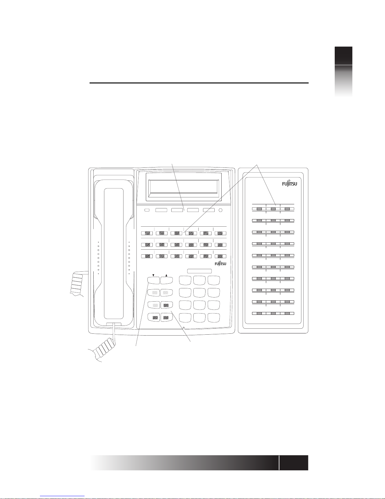
Figure 1-1: SRS-9924 National ISDN - Front Panel
1-2
NI / 5E Custom Terminal Overview
1
*
0 #
9
WXYZ
TUV
8
7
PQRS
GHI
4
JKL
5
6
MNO
DEF
3
ABC
2
1
SRS-9924
MENU
MSG
Multifunction Buttons
Softkeys
Function Keys Optional ABM
Volume/Contrast Buttons
DROP CONF
TRAN REDIAL
HOLD SPKR
13 14 15 16 17
MIC-OFF
789101112
123456
SRS-9924-ABM
21 22 23
24 25 26
27 28 29
30 31 32
33 34 35
36 37 38
39 40 41
42 43 44
45 46 47
18 19 20
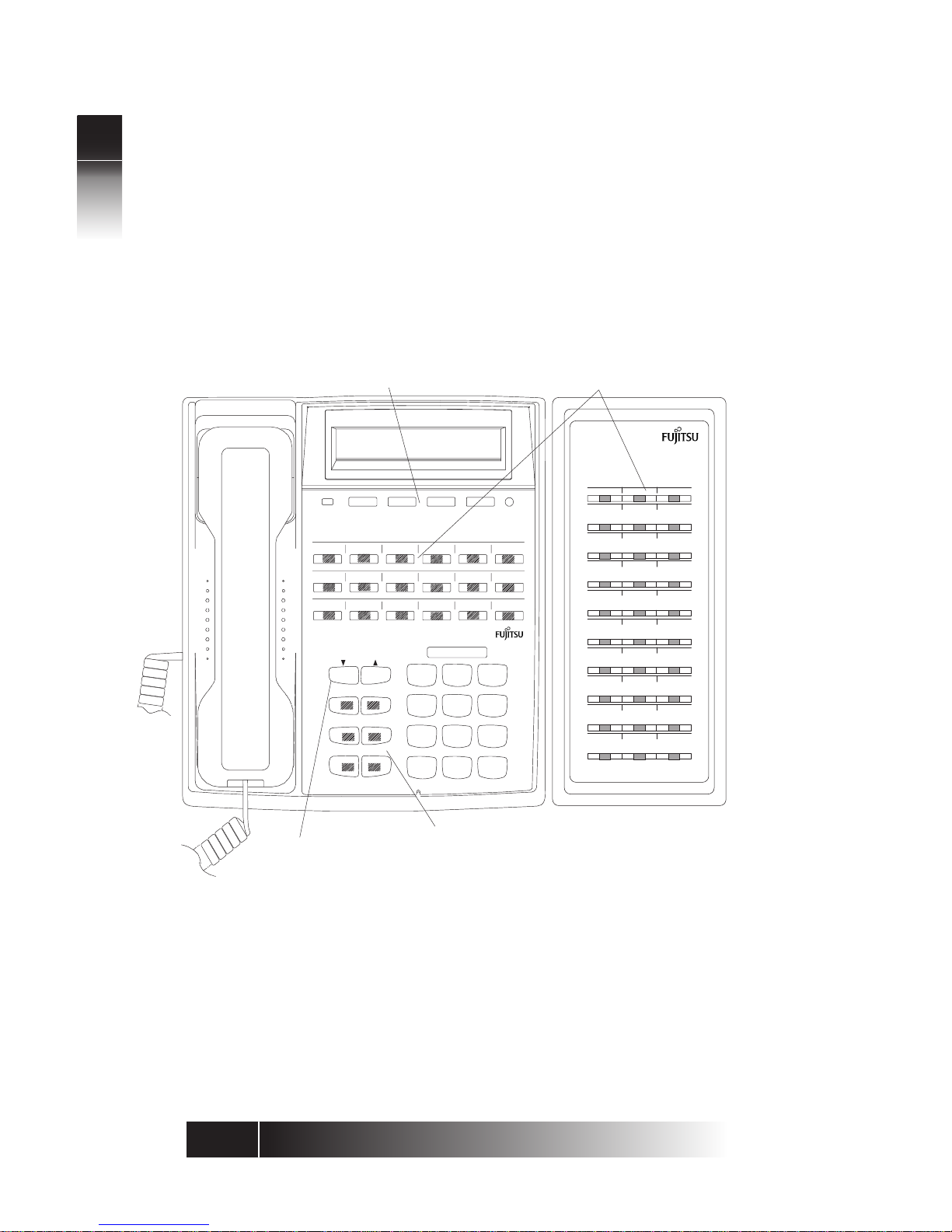
Figure 1-2: SRS-9924 5E Custom - Front Panel
1-3
NI / 5E Custom Terminal Overview
1
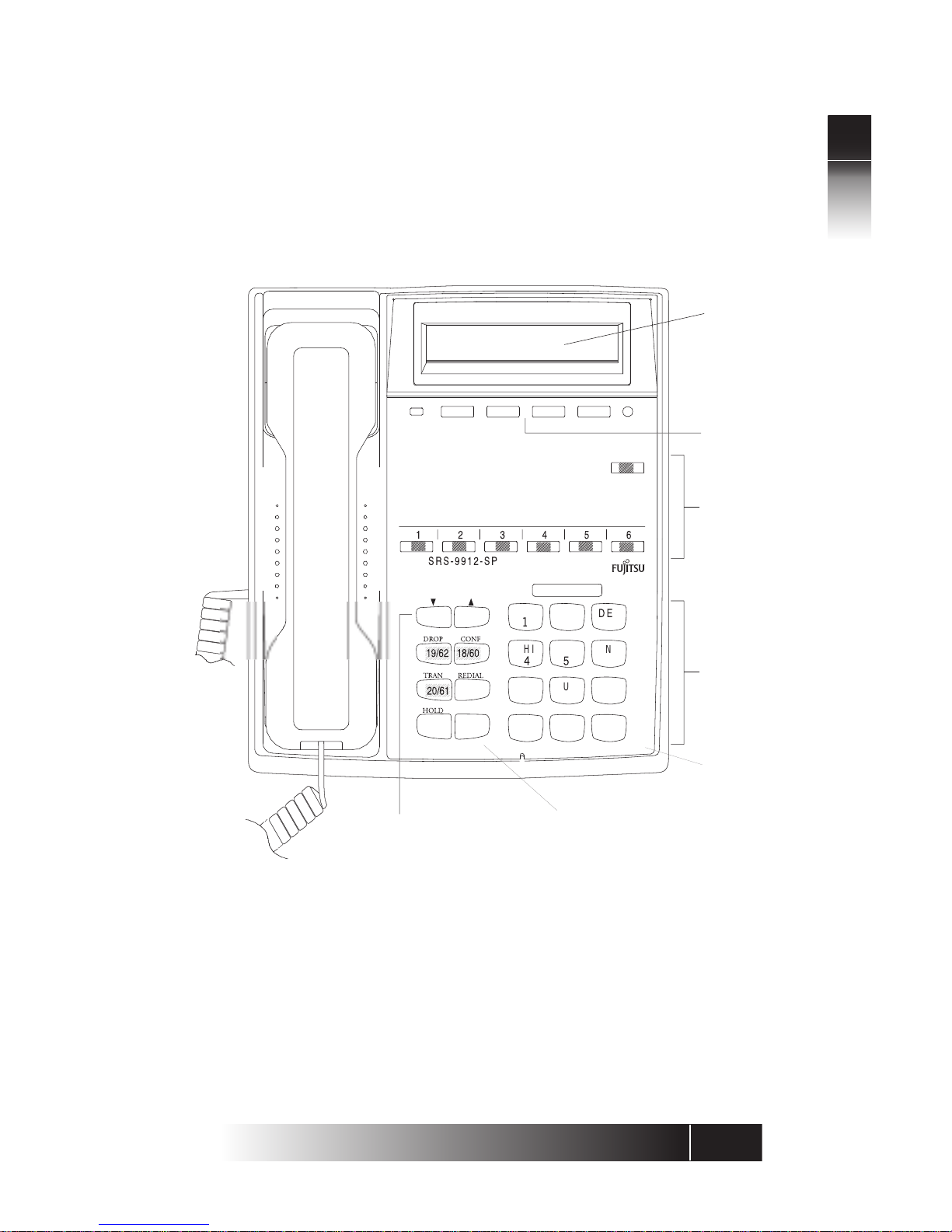
Figure 1-3: SRS-9912-SP National ISDN Front View
M
SG
63
Softke
ys
Multifuncti
on
B
uttons
Displa
y
Volume/Contras
t
B
uttons
Function Ke
ys
MENU
MIC-OFF
Numeri
c
Keypa
d
Microphon
e
0
9
WXY
U
V
8
PQR
S
G
J
6
O
3
C
SPKR
1-4
NI / 5E Custom Terminal Overview
1
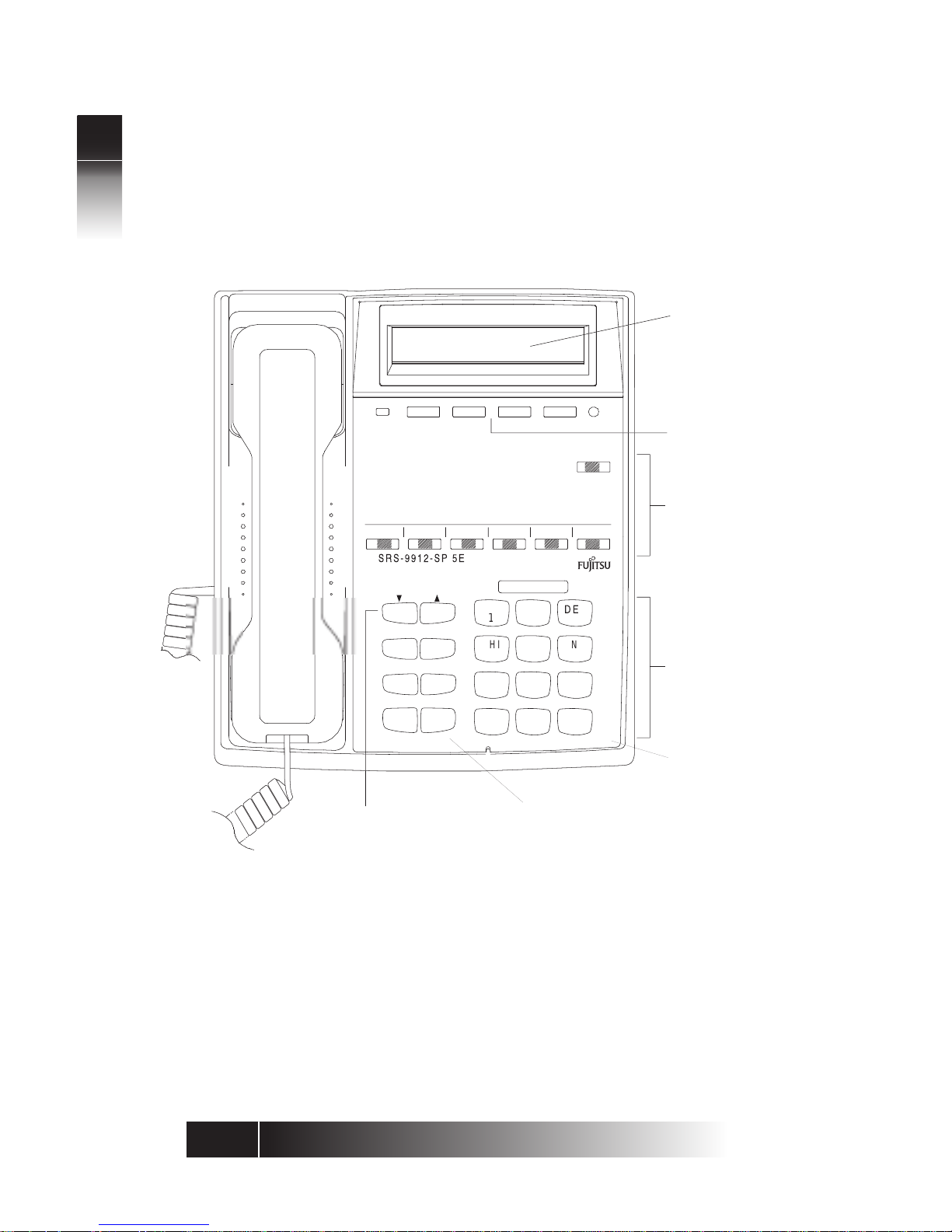
Figure 1-4: SRS-9912-SP 5E Custom National ISDN Front View
M
SG
63
Softke
ys
Multifuncti
on
B
uttons
Displa
y
Volume/Contras
t
B
uttons
Function Ke
ys
MENU
MIC-OFF
Numeri
c
Keypa
d
Microphon
e
0
9
WXY
TUV
8
7
PQRS
G
J
5
6
O
F
3
C
DR
OP
CONF
TRANREDIAL
HOLDSPKR
1-5
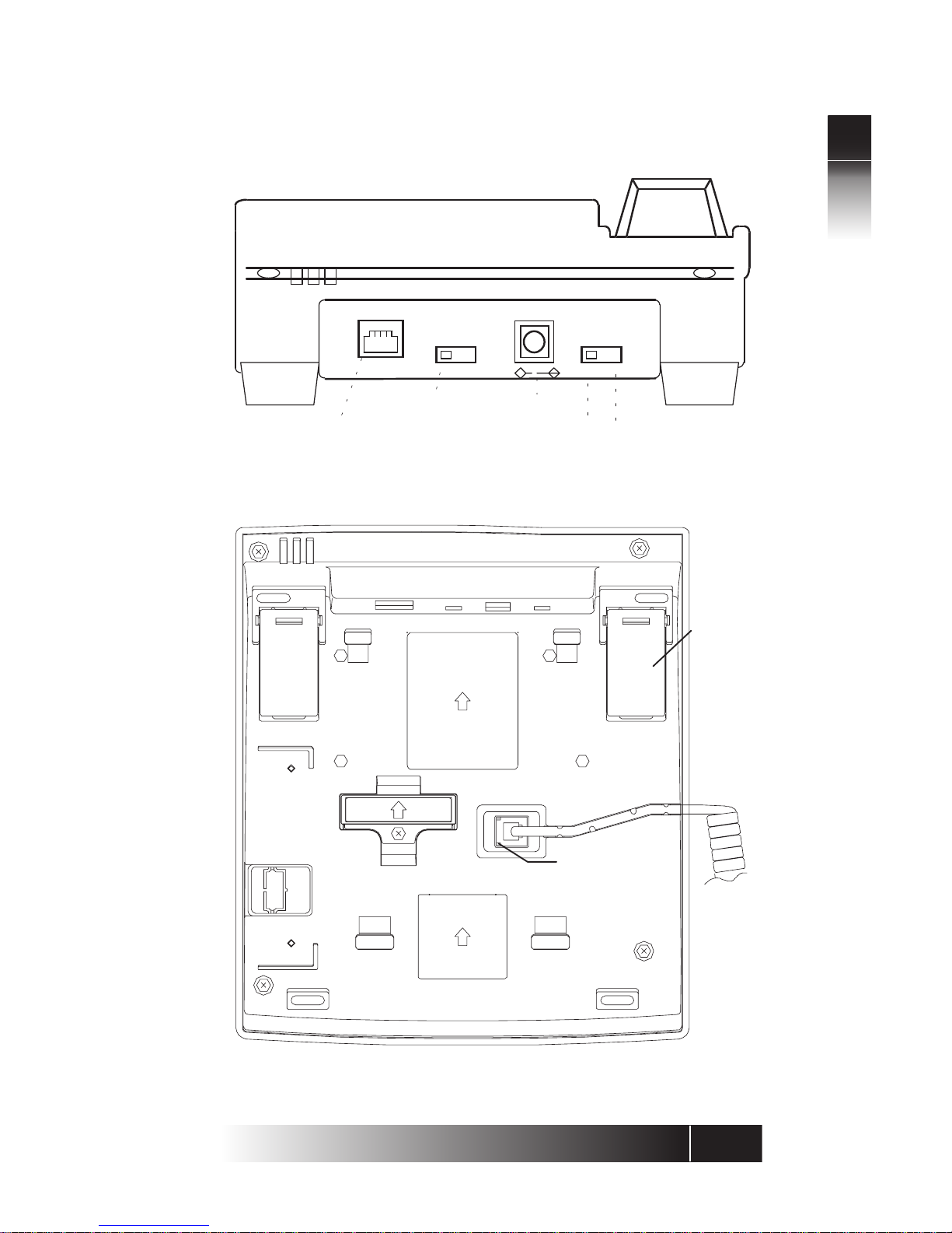
NI / 5E Custom Terminal Overview
1
Terminating
resistor
DC power connector
48V DC
OFF ON
PS
TR
OFF ON
LINE
Handset/Headset
connector located
beneath terminal
ISDN Line Connector
Power Source selection
C
Figure 1-5: Digital Set Rear View
Handset
/Headset
plug
Rear
stand
Figure 1-6: Digital Set Bottom View

1-6
NI / 5E Custom Terminal Overview
1
Switches and
Connectors
Unique Components
Softkeys/MENU. Four buttons below the display
with changeable functions. The MENU key displays
the current functions on line 2 of the display.
Multifunction buttons. These buttons are
assigned to CAs, DNs, one-touch numbers, or
network features. Dual assignments are not
supported. (For example: One-Touch and Call
Appearance)
Function keys. Single-touch keys for features,
consisting of DROP, CONF, TRAN, REDIAL, HOLD,
and SPKR.
Volume/Contrast buttons. Increase or decrease
display contrast (when no call is active), or speaker
volume (when a call is active).
T erminating r esistor. This built-in resistor, labeled
“TR”, provides a standard termination to the ISDN
line. The factory setting is OFF.
DC power connector . This connector, labeled “48
V DC”, provides an alternative to power delivered
through the ISDN line.
Power source selection. This switch may be used
in multiple terminal installations. ON = AC adapter
only; OFF = Power source 2 or AC adapter
ISDN line connector. Use this RJ-49 connector to
plug in the telephone line. Normally , the connector
also provides DC power for the set.
Handset/Headset connector. This jack, located
on the bottom of the set, allows you to connect
either a handset or a headset.
Message Waiting (labeled MSG)
Feature Activator 63 is utilized for Message W aiting.
The LED associated with each button may light
when a feature is activated. (Featur e dependent)
LED Indicators

1-7
NI / 5E Custom Terminal Overview
1
MIC-OFF Button
Function Keys
For Multifunction Keys:
An LED associated with each button slowly
flashes green for incoming calls, flashes red if a
call is on hold at your phone, and is steady red
when a call is active on your phone.
The upper right button on the array is used as a
MIC-OFF function key . When pressed, the MIC-OFF
key turns red and mutes the micr ophone, allowing
you to hold a private conversation.
MIC-OFF is de-activated by default when your digital
set is delivered. Set-up for the MIC-OFF buttons
described in Chapter 3.
The digital set has six function buttons. Three of
these are permanently assigned to local functions:
SPEAKER, HOLD, and REDIAL.
SPEAKER: (with LED indicator)
Enables/disables handsfree operation.
HOLD: Holds an active call
REDIAL: Redials the last number you dialed
CONFERENCE: (with LED indicator) Adds parties to
an existing call (Button 18)
NI utilizes Feature Activators 18 or 60
DROP: Disconnects last party added to a conference
call or disconnects a two-party call (Button 19)
NI utilizes Feature Activators 19 or 62
TRANSFER: (with LED indicator) Transfers a call to a
third party you dial or select (Button 20)
NI utilizes Feature Activators 20 or 61
Button assignments are identical between the
SRS-9924 and the SRS-9912-SP.
DROP CONF
TRAN REDIAL
HOLD SPKR
Figure 1-7:
Function Button
Layout
User-Assigned
Function Buttons
Permanent
Functions

1-8
NI / 5E Custom Terminal Overview
1
MULTIFUNCTION
BUTTONS
Multifunction buttons have three uses:
One-touch: Dial a stored number.
Network Feature: Activate or deactivate a special
network feature, such as call forwarding.
Call Appearance (CA) or Directory Number (DN):
Handles incoming or outgoing calls.
Use and set-up of the multi-function buttons is
covered in Chapters 2 and 3 respectively.
Special features such as call forwar ding are provided
by the ISDN network. These features are selected
by your System Administrator and assigned to
buttons on your phone during installation.
Appendix C describes frequently used
assignments and ordering codes for NI.
Each digital set associates its primary DN with
multifunction button 1. Multiple appearances of
the same DN are always on adjacent CA buttons.
(The button at the end of a row is “adjacent to” the
button beginning the next row up.)
Note: This guide uses the term directory number
appearances to refer to telephone numbers
that appear on more than one CA button.
The Nortel term for CAs that can handle more
than one call is Additional Functional Calls.
A telephone can also be assigned additional
DNs. Each such number can then be assigned
to adjacent buttons as well to allow multiple
call handling on that line.
Any DN assigned to one phone can also appear
on another phone, which can then share the use
of that line.
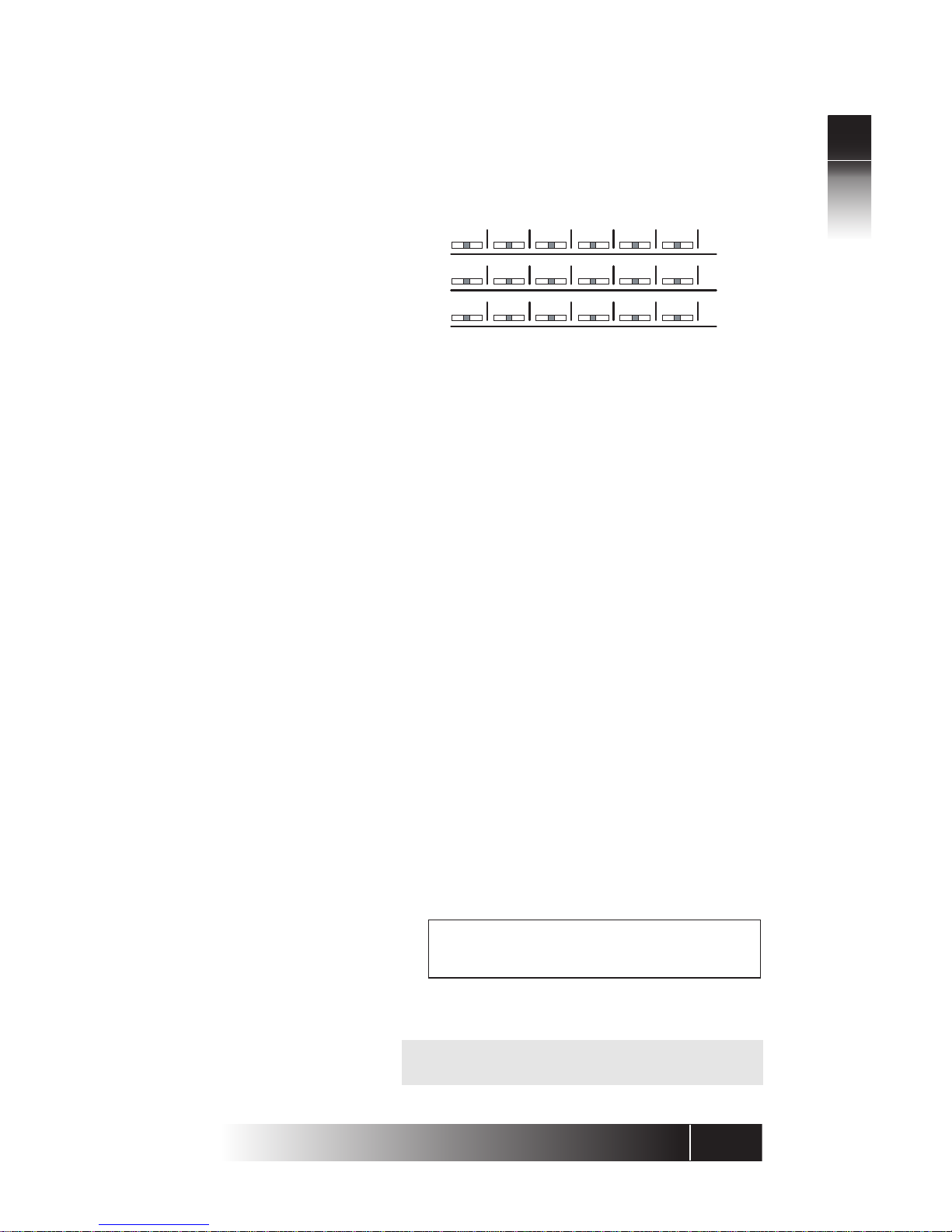
Figure 1-8 shows a digital set whose primary DN is
747-3456, with two additional CA buttons assigned
that same number. The telephone’ s secondary line
is 747-7890, which has two appearances.
Multiple Directory
Number
Appearances
Call Handling
Example with
Multifunction
Buttons
1-9
NI / 5E Custom Terminal Overview
1
In the illustration, this set also has a button assigned
to the number 747-3482. This could, for example,
be a shared line using someone else’s primary DN.
MIC-OFF
3456 3456 3456 7890 7890
3482
If your DN is 747-3456, and the first three
multifunction buttons on your digital set have been
assigned that number, you can have up to three
calls at the same time using that single DN, though
you can talk on only one at a time.
For example, if you have no calls in progress and
someone dials 747-3456, your telephone rings and
the LED for the first CA button associated with 747-
3456 flashes green. You can answer the call by
pressing that CA button and picking up the handset.
(The LED turns steady red.)
After answering the call, you can press the second
747-3456 CA button to originate another call. The
first call is automatically put on hold. If another
call comes in, you can press the third CA button
repr esenting 747-3456 to answer the third call. The
second call is also placed on hold.
Y ou would then have three calls on your 747-3456
DN. Only then is your 3456 number “busy”, that
is, when all three assigned CA buttons are in use.
747-3456
When you make a call, the number you dialed,
including any prefix, appears on line 1 of the display .
In 5E Custom ISDN, an ISDN Call identifier may
also appear. See Appendix D
CALL INFORMATION
DISPLAYS
Figure 1-8:
Example Line
Assignment SRS-9924
1-10
NI / 5E Custom Terminal Overview
1
For an incoming call, the calling party’s number
appears if the network supplies the digital set with
the Calling Line ID (CLID).
When your party answers, the call duration timing
is shown as minutes and seconds. This timer will
recor d for an hour , up to 59:59, and then it r estarts
at 00:00. If the call cannot go through, line 2 shows
a message such as “BUSY” or “NOT ANSWERED”.
15m
15s
777-1111
15:15
1=777-1111
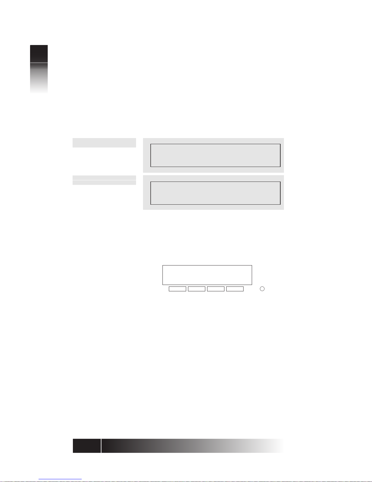
When you press MENU, line 2 of the display
changes to the names for the four keys directly
below the display (shown below). These keys are
called softkeys because the functions they control
change as you use the menus to set up different
features.
UNA L-DIR CLEAR OPTIONS
1234
Menu
Standard Softkey Layout
Note: Softkey 1 also serves as the ENTER key,
and Softkey 2 also serves as the NEXT key and
allows you to scroll thr ough the menu options.
These softkey functions are explained in the
following chapters:
UNA Chapter 2
L-DIR Chapter 2
CLEAR Chapter 3
OPTIONS Chapter 3
ENTER Chapter 3
Other names and functions for these keys are
explained in various contexts throughout the text.
NI ONLY
5E CUSTOM ONLY
SOFTKEYS AND
MENU

2-1
2
Using the Terminal
5E CUSTOM ONLY
Ringing Preference
LINE
PARAMETERS
Ringing
Preference
Choices
Menu Mode
Effects
When your line was installed, choices were made
on three important switch parameters that affect
your call handling and the LEDs associated with
your lines.
Ringing preference affects what happens when
you have at least one idle Call Appearance and an
incoming call flashing on another CA. When you
pick up the handset or press SPKR, the phone can
automatically connect you with an idle CA, giving
dial tone, or with the incoming call. Your phone
will consistently pick up an idle CA of the incoming
call based on the configuration choice recorded
with your telephone provider. When preference
is “yes”, the incoming call is chosen.
If the set is programmed at the switch to pick the
first ringing Call Appearance, picking up the
handset connects you immediately with the
incoming call. This preference setting is called
RING preference.
If the set is programmed to pick the first idle Call
Appearance, picking up the handset gives you a
dial tone. In this case, you must press the flashing
green Call Appearance button and pick up the
handset or press SPKR to answer an incoming call.
This setting is called IDLE preference.
During Menu Mode, you can answer any incoming
call by pressing the appropriate Call Appearance
button and picking up the handset. If your phone
was installed with “ringing preference” as RING,
then simply picking up the handset automatically
connects you to the first incoming call.
If the ringing preference is IDLE, then picking up
the handset or pressing SPKR connects you to an
idle line (if there is one). You can then make an
outgoing call or press a green-flashing Call
Appearance button to pick up an incoming call.
CHAPTER 2
USING THE FUJITSU TERMINAL

2-2
2
Using the Terminal
5E CUSTOM ONLY
(If your ringing prefer ence was set to IDLE and there
are no lines available, the terminal does not connect
to a line until you press a Call Appearance button.)
Autohold affects what happens when you are on
an active call on one CA and then press another
CA. The active call you were on can be dr opped or
held automatically. If it is dropped, the LED goes
dark. If it is held, the LED flashes red. Your phone
will consistently drop or hold your active call when
you press another CA based on the configuration
choice recorded with your telephone provider.
Onetouch affects whether handsfree operation is
automatically selected when you press an idle CA,
causing you to hear a dial tone through the speaker.
Your phone will consistently remain in handset
mode or automatically enter handsfree operation
based on the configuration choice recorded with
your telephone service provider. Please note this is
different fr om One-Touch buttons for placing calls,
which is described later in Chapter 2.
This guide assumes that handsfree operation is
automatic when you press an idle CA, that is
onetouch is “yes”. If your installation is different,
then to get dial tone after pressing an idle CA, you
must either press SPKR for handsfree operation or
lift the handset.
The SRS-9924 and SRS-9912-SP are equipped with
a speaker and microphone built-in to utilize
handsfree operation. In or der to place and receive
calls in the handsfree mode, you should be sure
that the MIC-OFF key feature is de-activated on the
button at the upper-right of the array.
AUTOHOLD
ONETOUCH
Guide
Assumptions
PLACING AND
RECEIVING CALLS

2-3
2
Using the Terminal
Placing
Handset Calls
If you are already
talking on another
call
1. Pick up the handset. This should automatically
give you a dial tone. If not, press the idle Call
Appearance (CA) you wish to use.
2. Dial the desired number.
3. Converse with the called party, then hang up.
1. End the call by pressing the button in the
handset cradle to get a dial tone. (Y ou can also
hang up the handset and pick it up again.) Or
Retain the call by pressing an idle CA button to
get a dial tone. (The call is automatically put on
hold.)
2. Converse with the called party, then hang up.
Or If you put your original call on hold, pick up
the call by pressing its red-flashing CA button.
Notes:
• The displayed call duration vanishes after about
three seconds after you hang up.
• Onhook dialing can be used to place calls.
Dial the number first, then pick up the handset.
The phone automatically dials the number. The
number entered remains available for dialing
for about three minutes.
1. Pick up the handset, and if necessary, press the
green flashing CA. The LED changes to steady r ed.
2. Converse with the calling party.
3. When your conversation ends, hang up by
replacing the handset in its cradle.
A handsfree call uses the integrated microphone
and speaker of the handset.
1. Press the SPKR button. Its LED will light red (if
not, press an idle CA) and you will hear a dial
tone.
2. Dial the desired number.
3. Converse with the called party.
4. Hang up by pressing the SPKR key.
(See also “Handsfree, Handset, and Headset
Modes”, in Chapter 3, “Local Features”.)
Receiving Handset
Calls
Placing
Handsfree Calls

2-4
2
Using the Terminal
Receiving
Handsfree Calls
1. Pr ess SPKR and, if necessary , the green-flashing
CA button.
2. Converse with the calling party.
3. Hang up by pressing SPKR.
Check that headset mode is activated on your
telephone. The handset, speaker, and microphone
will be disabled. All dialing tones and telephone
conversation will be audible only through the
headset. Your voice and any other transmitted
sounds will go through the headset microphone
only . Refer to Chapter 3 for instructions on how to
set-up headset mode.
1. Press SPKR. Its LED will light red and you will
hear a dial tone.
2. Dial the desired number.
3. Converse with the called party, then hang up
by pressing SPKR.
1. Press SPKR, and if necessar y, press the greenflashing CA button.
2. Converse with the calling party.
3. Hang up by pressing SPKR.
Note: These procedur es assume that the phone
is set to ringing line preference or primary
line preference.
Placing
Headset Calls
Receiving
Headset Calls

2-5
2
Using the Terminal
Switching
between Handset
and Handsfree
Modes
1. Press SPKR and then replace the handset in its
cradle. You now hear the other parties on the
call through the speaker.
2. If the MIC-OFF LED is r ed, the microphone has
been turned off. Press MIC-OFF to turn it back
on (the LED goes dark). The microphone now
picks up your voice.
3. Turn off the microphone by pressing MIC-OFF
again, to hold a private conversation with others
in the room. Pr essing MIC-OFF again turns the
microphone back on.
Note: If the MIC-OFF feature is not active on
the upper right corner multifunction button,
the microphone is always on.
Pick up the handset. Your call continues without
interruption. The handsfree speaker and
microphone are turned off.
5E CUSTOM ONLY
Placing a Call to a
Leased Network
Method 1
To call someone in a leased network from outside
the network, you must enter an access code. Also,
you must have some way of indicating to the ISDN
switch that the numbers you are entering represent
a leased network access code. You accomplish this
by entering a delimiter. See Chapter 3 regarding
how to assign one of your multifunction buttons
as the leased network access code delimiter key.
Enter all numbers before you pick up the handset
or press the SPKR button.
1. Dial the number of the person you want to call.
2. Press the access code delimiter button. A colon
appears on the screen after the number.
3. Dial the leased network access code. The access
code appears on the screen after the colon.
4. To start the call, pick up the handset or press
the SPKR button. Y our digital set automatically
sends the entered numbers and code to
connect to the leased network number.
If you are using
handsfree mode
and want to use
the handset
If you are using the
handset and want
to use handsfree
mode

2-6
2
Using the Terminal
5E CUSTOM ONLY
Method 2
Enter all numbers before you pick up the handset or
press the SPKR button.
1. Press the access code delimiter button. A colon
appears on the screen after the number.
2. Dial the leased network access code. The access
code appears on the screen after the colon.
3. Press the delimiter key again. Another colon
appears on the screen after the access code.
4. Dial the number of the person you want to call.
The number appears on the screen after the
second colon.
5. T o start the call, pick up the handset or press the
SPKR button. Y our digital set automatically sends
the entered numbers and code to connect to
the leased network number.
FUNCTION
BUTTONS
The terminal has six function buttons, located to
the left of the numeric keypad.
Three buttons are permanently assigned to local
functions (REDIAL, HOLD, and SPKR) and the other
three buttons ar e usually assigned to CONFerence,
DROP and TRANsfer.
On NI, Fujitsu supports two sets of telephone
company assignments for network based features.
On the labeled function buttons for CONF, DROP,
and TRAN, Fujitsu sets accept the following values
or feature activators:
CONFERENCE Button 18
Activator 18 or 60
DROP Button 19
Activator 19 or 62
TRANSFER Button 20
Activator 20 or 61
Note: The SRS-9924 and SRS-9912-SP use the
same button numbers and Feature
Activators for the user assigned function
keys.
NI ONLY

2-7
2
Using the Terminal
5E Custom
ONLY
These assignments are not used for 5E Custom
ISDN.
If there are no idle CA’s available, pressing REDIAL
brings the number to the screen but does not dial.
When an idle CA later becomes available, pressing
the CA button dials the number.
1. To use hold, press HOLD while you have an
active call in progress. The CA LED changes
from steady red to flashing red.
2. To reconnect with a call on hold, press its
flashing CA button. Its LED changes from
flashing red to steady red, and you are
reconnected.
The autohold feature automatically puts an active
call on hold whenever you press another CA.
Conference is a network-based feature that you
must subscribe to from your telephone company.
The number of conference call participants allowed
depends on the number specified when you
subscribe to the feature. Ask your System
Administrator how many participants are allowed.
After establishing the initial call, add participants
to the conference call by following these steps:
1. Press CONF.
The CONF button lights up. The initial call is
placed on hold, and the next available CA is
selected.
2. Dial the number of the person you want to add
to the conference.
or
Select any CA that is ringing or on hold.
REDIAL
Dials the last
number dialed
on this phone
HOLD
Retains
connection with
an existing call
until you can
return to it
CONFERENCE
Telephone
conferences
with multiple
participants
Setting Up a
Conference Call

2-8
2
Using the Terminal
• If the person answers, you can talk privately
before joining the conference.
• If the line is busy or the person does not
answer , pr ess DROP. Then press the flashing
CA button to return to the initial call.
• To retain the second party without having
a conference, press HOLD and then press
the flashing CA. This allows you to speak
to the initial caller while keeping the second
call on hold. T o make this a conference call,
press the CONF button and go to step 3.
3. Press CONF.
The CONF button stays lit to indicate that a
conference call is in progress.
If you have a conference featur e for more than three
parties, you may add more participants to the
conference by r epeating the preceding thr ee steps
as many times as required up to the maximum
number of participants.
Some installations leave the other conference
participants connected if you disconnect. Ask your
System Administrator whether your conference
feature works this way. Otherwise, when you
disconnect, all other conference participants are
disconnected also.
DROP is a network-based feature that you must
subscribe to from your telephone company.
Pressing DROP at the end of a regular two party
call does nothing. <DMS-100>
Pressing DROP at the end of a regular two-party
call disconnects the call or cancels the connection
with the last party added to a conference call.
<5ESS>
During a conference call, the DROP featur e allows
the originator of the call to drop the last participant
added. Other participants can drop out of the call
simply by hanging up.
Dropping Out of
the Conference
Call
DROP
 Loading...