

Page 1
Page 2

TABLE OF CONTENTS
CHAPTER 1 - PART NAMES AND FUNCTIONS ................................ 1-1
CHAPTER 2 –NETWORK SETTINGS ............................................... 2-1
DHCP SETTING (OPTION 13) ............................................................ 2-3
IP ADDRESS REGISTRATION (OPTION 14).......................................... 2-4
SUBNETMASK REGISTRATION (OPTION 15)....................................... 2-5
DEFAULT GATEWAY ADDRESS REGISTRATION (OPTION 17) ............... 2-6
FEATURE GATEWAY ADDRESS REGISTRATION (OPTION 16)............... 2-7
VLAN SETTING (OPTION 20) ............................................................ 2-8
CHAPTER 3 – SERVICE SETTINGS .................................................. 3-1
FEATURE GATEWAY ALIAS SETUP (OPTION 28) ................................. 3-1
SETTING-UP SPID (OPTION 8) ........................................................... 3-2
KEY ATTRIBUTES CONFIGURATION (OPTION 9) ................................ 3-6
DOWNLOAD ................................................................................... 3-7
MANUAL CONFIGURATION. ............................................................. 3-8
SNTP SERVER ADDRESS SETUP (OPTION 18) ................................... 3-18
DAYLIGHT SAVINGS SETTING (OPTION 21) ..................................... 3-19
TIME ZONE SETUP (OPTION 22) ..................................................... 3-20
JITTER BUFFER SIZE (OPTION 26) ................................................... 3-21
TOS / DIFFSERV SETUP (OPTION 23) .............................................. 3-22
RTP PORT REGISTRATION (OPTION 24) ........................................... 3-25
OPTIONAL FTP ADDRESS SETUP (OPTION 97)................................. 3-27
Fujitsu IP Centrex Telephone Table of Contents & Intro
CHAPTER 4 – PASSWORD SETTINGS ............................................. 4-1
USER PASSWORD REGISTRATION (OPTION 19) ................................. 4-1
ADMINISTRATOR PASSWORD REGISTRATION (OPTION 27) ................ 4-2
CHAPTER 5 – SOFTWARE DOWNLOAD ........................................ 5-1
OPTIONAL FTP ADDRESS SETUP (OPTION 97)................................... 5-1
CHAPTER 6 – MASTER CLEAR & PASSWORD RESET ....................... 6-1
MASTER CLEAR (OPTION 96) ............................................................ 6-1
PASSWORD RESET. ........................................................................... 6-1
1
Page 3

Fujitsu IP Centrex Telephone Table of Contents & Intro
APPENDIX A - ERROR MESSAGES. ................................................. A-1
TABLE A-1 CONNECTION STATUSMESSAGES ..................................... A-1
TABLE A-2 NATIONAL STANDARDIZED CAUSE VALUES ...................... A-2
TABLE A-3 NETWORK SPECIFIC CAUSE VALUES. ................................ A-3
TABLE A-4 UNIFORM CAUSE VALUES ................................................ A-3
TABLE A-5 LAN CONNECTION STATUSMESSAGES .............................. A-4
APPENDIX B – SELF-TESTING ........................................................ B-1
PERFORMING SELF-TEST................................................................... B-1
LED TEST ......................................................................................... B-2
KEY TEST (22) ................................................................................... B-2
TONE TEST (16) ............................................................................... B-4
RINGER TEST (17)............................................................................. B-4
LCD TEST (11) .................................................................................. B-5
HOLD TONE CHECK (18) ................................................................. B-6
KEY TOUCH TONE TEST (19) ............................................................ B-6
PING TEST (9) .................................................................................. B-7
DSP CODER LOOPBACK ................................................................... B-8
MAC ADDRESS DISPLAY (20) ........................................................... B-10
END OF SELF-TEST ......................................................................... B-10
APPENDIX C – MISCELLANEOUS AND GLOSSARY .......................... C-1
QoS SETTINGS (TOS AND DIFFSERV) ................................................ C-1
Drawing 1: Correlation between TOS and DSCP. ........................... C-1
Drawing 2 : Mapping of DSCP and TOS precedence ..................... C-2
JITTER BUFFER SETTING PARAMETER SETTING .................................. C-3
PORT NUMBER ................................................................................ C-3
AUTOMATIC ADJUST VOICE PACKET LENGTH ................................... C-3
RTP PORT. ........................................................................................ C-3
RTCP. ............................................................................................... C-3
GLOSSARY ....................................................................................... C-4
2
Page 4

WARNING
The Fujitsu SRS-12i / 24i IP Centrex Telephone(s) has been tested and found
to comply with the limits for a Class B digital device, pursuant to Part 15 of
the FCC rules. These limits are designed to provide reasonable protection
against harmful interference in a residential installation. This equipment
generates, uses, and can radiate radio frequency energy and, if not installed
and used in accordance with the instructions, may cause harmful interference
with radio communications. However, there is no guarantee that interference
will not occur in a particular installation. If this equipment does cause harmful
interference with radio or television reception, which can be determined by
unplugging the equipment to turn it off, the user is encouraged to try to
correct the interference by one of the following measures:
• Reorient or relocate the receiving antenna of the affected receiver.
• Increase the separation between the equipment and the affected
receiver.
• Consult a dealer or experienced radio or television technician for help.
Changes or modifications not expressly approved by the party responsible
for compliance could void the user’s authority to operate the equipment.
FCC REQUIREMENTS
The Fujitsu SRS-12i / 24i IP Centrex Telephone complies with Part 68 of the
FCC Rules. The FCC Part 68 Label is located on the bottom of the enclosure.
This label contains the FCC Registration Number for this equipment. If
requested, this information must be provided to your telephone company.
Fujitsu IP Centrex Telephone Table of Contents & Intro
Your telephone company may make changes in its facilities, equipment,
operations or procedures that could affect the proper functioning of your
equipment. If they do, you will be notified in advance to give you an
opportunity to maintain uninterrupted telephone service.
The Fujitsu SRS-12i / 24i IP Centrex Telephone handset is hearing-aid
compatible (HAC) per Section 68.316, FCC Rules and Regulations.
3
Page 5

Fujitsu IP Centrex Telephone Table of Contents & Intro
REPAIRS
Repairs to this equipment may only be made by the manufacturer or its
authorized agents. If this equipment is causing harm to the telephone
network, the telephone company may request that it be unplugged from
the modular outlet until the problem has been corrected. To obtain repair
service or warranty information, contact:
Repair Center
Fujitsu Network Communications, Inc.
1000 Saint Albans Drive,
Raleigh, NC 27609
1-800-298-9007
IMPORTANT SAFETY INFORMATION
The Fujitsu SRS-12i / 24i IP Centrex Telephone should be used in accordance
with all instructions and precautions provided in this guide.
• Read and understand all instructions.
• Install cords where they cannot be a hazard to anyone walking nearby.
•Use only the line cable included with the telephone.
• Do not use this product near water, for example, near a bathtub,
washbowl, kitchen sink, laundry tub, in a wet basement, or in a
swimming pool.
•Avoid using the telephone during an electrical storm. There may be a
remote risk of electrical shock from lightning.
•Do not use the telephone to report a gas leak in the vicinity of the leak.
•Do not open the telephone or the warranty will be voided.
•Only authorized personnel should perform service on hardware
components.
•Use your one-touch numbers for storing emergency numbers.
•Do not use liquid cleaners or aerosol cleaners on the telephone; use a
damp cloth with rubbing alcohol for cleaning.
•Do not place the telephone on an unstable cart, stand, or table. The
telephone may fall causing serious damage to the telephone.
•Never push objects of any kind into this telephone as they may touch
dangerous voltage points or short out parts that could result in a risk of
fire or electric shock. Never pour liquid of any kind on the telephone.
4
Page 6

GENERAL INFORMATION
The Fujitsu SRS-12i / 24i IP Centrex Telephone offers enhanced digital Centrex
features. Following is the list of some of the popular features (some of which
may need to be supported by your service provider as well):
• Auto SPID and parameter download Support
• Full key system functionality
• Call preferences
• Call appearance reservation
• Simplified conference and transfer
• Hold
• Address book function for 50 items
• Intercom voice announce/auto answer
•One-button access to advanced Centrex features
•Hearing aid compatible handset
•Headset/handset operation
•Handset volume control (ADA compliant)
• Speakerphone for hands-free operation
• Local one-touch speed dialing
• Fully automatic last number redial capability
•Unanswered/Incoming call logging (52 calls max.)
•Out going call logging (52 calls max.)
• Call duration display
•Programmable smart-pause feature
• LCD display of 2 lines by 24 characters
•Tilt set for improved viewing angle
•Out of bound signaling for DTMF
• Remote software update
•Message waiting indication
• Ringer volume options, including “extra high”
• Ringer mode options, including mute ring or one ring
Fujitsu IP Centrex Telephone Table of Contents & Intro
CONTENTS OF FUJITSU IP CENTREX TELEPHONE SHIPMENT
The Fujitsu SRS-12i / 24i IP Centrex Telephone comes with the following
parts necessary for operation of your telephone. Verify that all are included
prior to beginning installation.
1 – IP Centrex Telephone (SRS-12i / 24i), 1 – Handset, 1 – Handset Cord, 1 –
Category 5 Ethernet Line Cord, 1 – User Guide (CD), 1 – Quick Reference
Card, 1 – Telephone Clear Cover, and Paper Template(s). AC Adaptor (Power
Supply) is sold separately.
5
Page 7

CHAPTER 1 – PART NAMES AND FUNCTIONS
SRS-12i (front view)
1
Speaker
Speaker
Display
Softkeys
Multi-function
Buttons
Microphone
Function
Buttons
SRS-24i (front view)
Display
Softkeys
Multi-function
Buttons
Function
Buttons
Fujitsu IP Centrex Telephone Part Names and Functions
Microphone
1-1
Page 8
1
Fujitsu IP Centrex Telephone Part Names and Functions
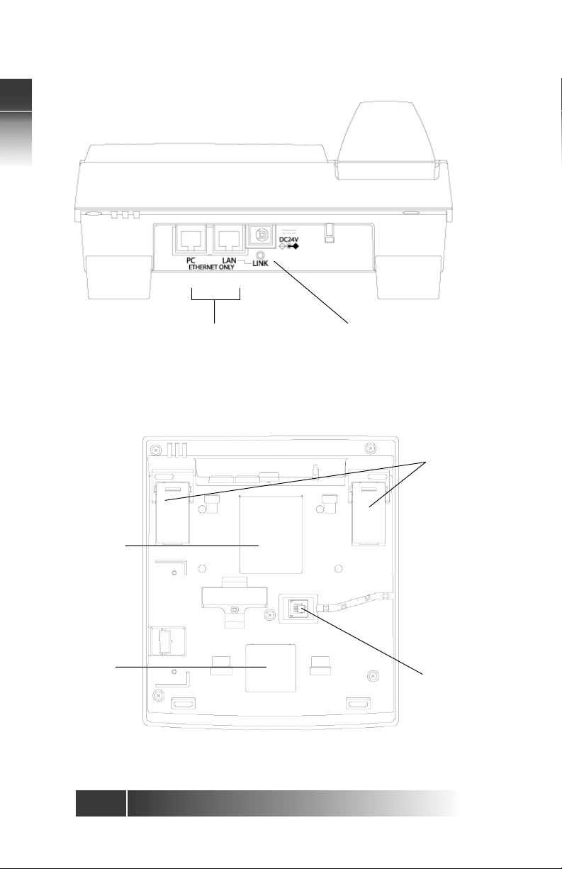
Product
Label
FCC
Label
LAN & PC Connection
(10/100 Ethernet)
SRS-12i / 24i (rear view)
DC Power
Connection
Rear
Leg
Hand/headset
Connection
1-2
SRS-12i / 24i (botom view)
Page 9

Display – Shows the call state, caller ID, dialed digits, network call control
messages, and elapsed time during calls. When not on a call, the date and
time of day are displayed.
Multifunction Buttons – These buttons are assigned to call appearances or
network features or one-touch numbers. Dual assignments such as OneTouch and Call Appearance are not supported.
Function Buttons – Single-touch buttons for features, consisting of ADR
BOOK, CALL LOG, DROP, CONF, TRAN, REDIAL, HOLD, and SPKR.
•ADR BOOK – Allows access to store/retrieve phone numbers stored in
the telephone.
• CALL LOG – Shows lists of calls for both unanswered / answered
incoming and outgoing calls.
• DROP – Disconnects the last party added to a conference call, or
disconnects from a call when not in conference mode on some C.O.
Switches.
•CONF – Enables multiple parties (3 typically) to be on one call.
• TRAN – Places the current call on hold, selects an idle call appearance
for dialing another number so a call can be transferred.
• REDIAL – Dials the last number dialed on the phone.
• HOLD – Places existing call on hold.
• SPKR – Enables / disables the hands-free mode. When the speaker is in
use, a red indicator on the key is lit
Volume/Contrast Buttons – Increase or decrease display contrast (when
no call is active), or speaker / handset volume (when a call is active).
Message Indicator – A bright red indicator is lit when messages are waiting;
controlled by the network.
Numeric Keypad – Allows the user to dial telephone numbers, and send
DTMF tones to external equipment such as voice mail systems.
MIC-OFF Button – When pressed, the MIC-OFF key turns red and mutes the
handset and speaker MIC, this allows user to hold a private conversation.
MIC-OFF is de-activated as the default state.
Buttons – Used for volume control, LCD contrast, and toggling
up and down the option menu.
LAN Connector – Connector for the LAN cable.
PC Connector – Connector for a cable to a PC.
Power Connector – Connector for the AC Adaptor. Listed AC Adaptor marked
“Class 2” and rated 24V DC, 500mA should be used for this product.
LAN Lamp – A green indicator is lit when the system is successfully connected.
Rear Legs – Adjusts height of the set.
Handset/Headset Connector – Connects the Handset/Headset cord to the
telephone.
1
Fujitsu IP Centrex Telephone Part Names and Functions
1-3
Page 10

1
Product Label – Product Model, Part Number, Serial Number, MAC Address,
and UL Certification information.
FCC Label – Information on FCC Part 68 and HAC compliance.
Fujitsu IP Centrex Telephone Part Names and Functions
1-4
Page 11
CHAPTER 2 – NETWORK SETTINGS
The following procedure will help a System Administrator, installer, or user to
easily set up a Fujitsu SRS-12i / SRS-24i IP Centrex Telephone.
2
2-1
Fujitsu IP Centrex Telephone Network Settings
Page 12

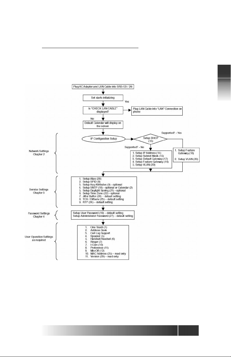
These instructions are intended mainly for System Administrators, service
personnel or end users who are installing the Fujitsu SRS 12i / 24i IP Centrex
Telephone. Please refer to the Initial Setup Procedure Diagram.
Required Installation Steps
2
Fujitsu IP Centrex Telephone Network Settings
Connecting a Fujitsu IP Centrex Telephone to the network
Use Category 5 Ethernet cable or better to connect the LAN jack on the
telephone to the LAN.
Upon receipt of the Fujitsu SRS-12i / 24i IP Centrex Telephone, plug the local
network line into the LAN jack on the back of the set. If the display shows a
date and time, the set is powered. Always make sure the connection is properly
installed. If the display does not light up, assistance from your System
Administrator to complete the installation may be required.
Warning:
Never try to use other types of cables on the set. This might cause damage
to the set. Do not work on the system or connect or disconnect cables during
periods of lightning activity.
Connecting a Fujitsu IP Centrex Telephone to PC
The Fujitsu SRS-12i / 24i Centrex Telephone has repeating Ethernet ports
that will allow a PC to be connected to it. Use Category 5 Ethernet cable or
better to connect the PC to the PC jack on the phone.
Power
Currently an AC/DC Adaptor must be used to operate the Fujitsu SRS-12i /
24i IP Centrex Telephone. The adaptor provides DC power at 24 Volts DC.
(The SRS-12i and SRS-24i are not yet compatible with the future IEEE 802.3af
standard for LAN-based power.) Plug the AC/DC Adaptor connecter into the
round power jack on the rear of the telephone. This product relies on the
building’s installation for short-circuit protection. Ensure that a fuse or circuit
breaker no larger than 120 Volts AC, 15A U.S. is used for the circuit.
2-2
Page 13

DHCP Setting (Option 13)
DHCP is a Dynamic Host Automatic Configuration Protocol that allows a
server to dynamically assign IP addresses to workstations.
1. Press OPTIONS, numeric key “1”, “3”, then ENTER.
DHCP SETTING
SUPPORTED
(If NON SUPPORTED was selected previously, the screen will show
“NON SUPPORTED.”)
2. Press ENTER.
ENTER USER PASSWORD
3. Enter 4 digits of numeric password (see User Password Registration in
chapter 4).
ENTER USER PASSWORD
****
* Factory Default User Password - 9999
4. Press ENTER.
1: SUPPORT 2: NO SUPPORT
(SELECT 1-2)
5. Press 1, then ENTER for support of DHCP. (Or press 2, then ENTER to
deactivate support of DHCP.)
SUPPORTED
COMPLETED
2
6. Press OPTIONS to exit the option menu. The telephone will reboot
automatically.
When 1: SUPPORT is selected, but the set could not obtain IP address, the
following error message will be shown:
DHCP Outage
User can manually enter the IP Address by going back to Menu by pressing
OPTIONS while DHCP ERROR message is displayed.
(See IP Address Registration Option 14 in this chapter).
Press either asterisk (*) to go back to sub-menu or OPTIONS to exit the option
menu.
2-3
Fujitsu IP Centrex Telephone Network Settings
Page 14

2
IP Address Registration (Option 14)
When the DHCP is not supported, the IP address registration is required in
order to operate the telephone. To register the IP Address, follow the steps
below:
1. Press OPTIONS, numeric key “1”, “4”, then ENTER.
IP ADDRESS REGISTRATION
IP=10.36.213.210
Fujitsu IP Centrex Telephone Network Settings
2. Press ENTER.
ENTER USER PASSWORD
3. Enter 4 digits of numeric password (see User Password Registration in
chapter 4). Then, ENTER.
ENTER USER PASSWORD
****
* Factory Default User Password - 9999
4. Enter IP Address.
ENTER IP ADDRESS
IP=10.36.213.210
If the IP address is already registered, the last saved address is displayed. In
order to input a new IP address, simply enter it. Press “#” key when the input
of a dot (.) is required.
ENTER IP ADDRESS
IP=10.36.213.170
Note:
If you don’t want to change the IP Address, just press ENTER.
5. Press ENTER.
COMPLETED
Press either asterisk (*) to go back to sub-menu or OPTIONS to exit the option
menu.
2-4
Page 15

Subnet Mask Registration (Option 15)
When the DHCP is not supported, the Subnet Mask registration is also required
in order to operate the telephone. To register the Subnet Mask address,
follow the steps below:
1. Press OPTIONS, numeric key “1”, “5”, then ENTER.
SUBNET MSK REGISTRATION
SN=10.36.213.210
2. Press ENTER.
ENTER USER PASSWORD
3. Enter 4 digits of numeric password (see User Password Registration in
chapter 4). Then ENTER.
ENTER USER PASSWORD
****
* Factory Default User Password - 9999
4. Enter Subnet Mask Address. If Subnet Mask address has been entered
already, the last address is displayed.
ENTER SUBNET MASK
SN=255.255.255.0
In order to input a new Subnet Mask, simply enter the new address. Press
“#” key when the input of a dot (.) is required
Note:
If you don’t want to change the Subnet Mask, just press ENTER.
5. Press ENTER.
2
COMPLETED
Press either asterisk (*) to go back to sub-menu or OPTIONS to exit the option
menu.
2-5
Fujitsu IP Centrex Telephone Network Settings
Page 16

2
Default Gateway Address Registration (Option 17)
When the DHCP is not supported, the Default Gateway Address is also
required in order to operate the telephone. To register theDefault Gateway
Address, follow the steps below:
1. Press OPTIONS, numeric key “1”, “7”, then ENTER.
GW ADR REGISTRATION
GW=10.36.213.210
Fujitsu IP Centrex Telephone Network Settings
2. Press ENTER.
ENTER USER PASSWORD
3. Enter 4 digits of numeric password (see User Password Registration in
chapter 4). Then ENTER.
ENTER USER PASSWORD
****
* Factory Default User Password - 9999
4. If the Gateway Address is already registered, the last saved address is
displayed. In order to input a new Gateway Address, simply enter it.
Press “#” key when the input of a dot (.) is required.
ENTER GW ADDRESS
GW=10.36.213.210
Note:
If you don’t want to change the Gateway Address, just press ENTER.
5. After inputting a new Gateway Address, press ENTER.
COMPLETED
Press either asterisk (*) to go back to sub-menu or OPTIONS to exit the
option menu.
2-6
Page 17

Feature Gateway Address Registration (Option 16)
The Feature Gateway Address is required in order to operate the telephone.
To register the Feature Gateway Address, follow the steps below:
1. Press OPTIONS, numeric key “1”, “6”, then ENTER.
FGA ADR REGISTRA TION
FG=10.36.213.210
2. Press ENTER.
ENTER USER PASSWORD
3. Enter 4 digits of numeric password (see User Password Registration in
chapter 4). Then ENTER.
ENTER USER PASSWORD
****
* Factory Default User Password - 9999
4. After inputting the password, the LCD displays as below. If Feature
Gateway Address is already registered, the last address will be displayed.
ENTER FGA ADDRESS
FG=10.36.213.210
In order to input a new Feature Gateway Address, simply enter the
new address.
5. Enter New Gateway Address.
ENTER FGA ADDRESS
FG=10.36.213.171
2
FGA is set up as a default upon shipment from manufacturer. To
overwrite, simply enter the new FG Address. Press “#” key when the
input of a dot (.) is required.
Note:
If you don’t want to change the Feature Gateway Address, just press ENTER.
6. Press ENTER.
COMPLETED
Press either asterisk (*) to go back to sub-menu or OPTIONS to exit the option
menu.
2-7
Fujitsu IP Centrex Telephone Network Settings
Page 18

VLAN Setting (Option 20)
The VLAN Setting is required in order to operate the telephone. To select
the VLAN Setting, follow the steps below:
2
1. Press OPTIONS, numeric key “2”, “0”, then ENTER.
2. Press ENTER.
Fujitsu IP Centrex Telephone Network Settings
3. Enter 8 digits of numeric password (see Administrator Password
Registration in chapter 4). Then ENTER.
* Factory Default Administrator Password - 99999999
4. LCD will display as below:
When you select 2: NO SUPPORT, and ENTER, the LCD will display as
below:
VLAN SETTING
NON SUPPORTED
ENTER ADM PASSWORD
ENTER ADM PASSWORD
********
1: SUPPORT 2: NO SUPPORT
(SELECT 1-2)
NON SUPPORTED
COMPLETED
After this message is displayed the telephone will reset and the options
selected above will be implemented
When you select 1: SUPPORT, go to step 5 below.
5. Press 1: SUPPORT, then ENTER.
VLAN ID REGISTRATION
ID=2 (SELECT 2-4094)
6. To overwrite, simply enter the new value between 2-4094. Then
ENTER.
VLAN ID REGISTRATION
ID=2000 (SELECT 2-4094)
2-8
Page 19

7. You now need to enter VLAN PRI value.
VLAN PRI REGISTRATION
PRI=7 (SELECT 1-7)
To overwrite, simply enter the new value between 0-7.
VLAN PRI REGISTRATION
PRI=2 (SELECT 1-7)
8. Press ENTER.
SUPPORTED ID=2000 PRI=2
COMPLETED
After this message is displayed the telephone will reset and the options
selected above will be implemented.
2
2-9
Fujitsu IP Centrex Telephone Network Settings
Page 20
CHAPTER 3 – SERVICE SETTINGS
Feature Gateway Alias Setup (Option 28)
The Feature Gateway Alias registration is necessary in order to operate the
telephone. Your service provider will provide the Alias. Contact your service
provider for more details.
1. Press OPTION, numeric key “2”, “8”, then ENTER.
FGA ALIAS REGISTRATION
AL=91979012340101
2. Press ENTER.
ENTER USER PASSWORD
3. Enter 4 digits of numeric User Password (see User Password Registration
in chapter 4). Then ENTER.
ENTER USER PASSWORD
****
* Factory Default User Password - 9999
4. The screen will display the last Alias entry saved.
FGA ALIAS REGISTRATION
AL=91979012340101
Start entering the new Alias address.
FGA ALIAS REGISTRATION
AL=9
3
Enter up to 20 characters for this address.
FGA ALIAS REGISTRATION
AL=91979012340101
Press CLEAR to re-enter the address in case of an entry error.
5. Press ENTER.
FGA ALIAS REGISTRATION
COMPLETED
Press either asterisk (*) to go back to sub-menu or OPTIONS to exit the option
menu.
3-1
Fujitsu IP Centrex Telephone Service Settings
Page 21
Setting-Up SPID (Option 8)
The Service Profile Identifier (SPID) identifies your set to the network. The
SPID for your phone may be given to you by your service provider, or it may
be downloaded automatically by the C.O. switch at installation.
Auto SPID
If your C.O. switch supports Auto SPID, this function starts when either the
telephone is powered-on and a SPID is not present, or when the SPID has
3
Fujitsu IP Centrex Telephone Service Settings
been manually cleared.
Auto-SPID displays the following screens:
If only one SPID is available, the SPID is assigned, and the following screen is
displayed:
If two or more SPIDs are available, select one as follows.
Scroll through the available SPIDs. Press (up) and (down) keys to scroll
through the SPID numbers.
Press ENTER when the “>” is pointing to the correct SPID.
AUTO SPID REQUESTING
01010101010101
SPID SELECTION COMPLETED
50555512120101
1>50555512120101 SP/AU/PB
50555512130101
SPID SELECTION COMPLETED
50555512120101
After SPID selection is completed, the telephone will automatically request a
parameter download from the C.O. switch. The set will be ready to use once
the download is complete.
3-2
Page 22

Manual SPID Entry
1. Press OPTIONS, numeric key “8”, then ENTER.
The message ENTER SPID appears, with the current SPID number (if any)
shown below it.
ENTER SPID
ID=01010101010101
2. Key your SPID number and press ENTER. The calendar display will be
shown.
12:59AM SUN APR30
3
3-3
Fujitsu IP Centrex Telephone Service Settings
Page 23

Note:
For first time installations, download will occur without unplugging and
plugging the AC adaptor from/into the telephone.
At initial installation, when ENTER is pressed to save the SPID, the telephone
automatically requests a download from the C.O. switch. This downloading
function will work on switches that support parameter downloading
(including Nortel’s proprietary version – SPM).
Although each service provider can decide the number of characters and
format of the SPID, most have agreed on a simple format.
3
Fujitsu IP Centrex Telephone Service Settings
This format, referred to as generic SPID format, is likely to be the format used
by your service provider.
The generic SPID format consists of 14 digits: (10 digit Directory Number) +
4 digits (usually “0101”).
The first component is the main telephone number of the telephone, including
the area code. For example, 919 796 2000.
The most frequently assigned SPID will be the following: NPA XXX XXXX
0101.
If your service provider has not supplied a SPID, try the format shown above.
If it does not work, contact your service provider or System Administrator.
Occasionally, if the switch is very busy, the download may be delayed for a
short time. The telephone will continue to request a download until it is
successful, or until it receives a message from the switch indicating that a
manual configuration is needed.
The telephone also supports two other functions associated with parameter
downloading.
Warning:
Do not change your SPID unless told to do so by your service provider. In
most cases, digital sets will not work without the correct SPID number. If the
SPID number is wrong, the set displays the message SPID NG. Enter the
correct SPID number, then manually request a download. See Menu OPTIONS
9 for a description of the manual download process.
1. Service Profile Change Notification. If a request is made to change your
service configuration, when that change is completed in the central
office, the switch typically notifies the telephone that a change has
occurred. The telephone then requests a download from the switch to
update its configuration. This occurs automatically. The switch will
automatically initiate a download to the telephone when it is idle.
If a manual configuration has been used to reassign features, the settings
that differ from the downloaded settings will be removed.
2. The telephone provides a manual download function that allows for a
“request a download” if the information in the telephone seems incorrect.
Instructions for manual download are in the Key Attribute section.
3-4
Page 24

Loading or Modifying Network Data (after entering the SPID)
This section explains how to use the KEY-ATTR feature in menu mode to load
or modify network data. Enter network assignments using KEY-ATTR if the
set is connected to a switch that does not support the telephone downloading
function.
If the switch has downloaded network data automatically, use these
procedures to modify the set configuration to conform to the desired personal
preferences. In these procedures, select a button on the telephone and assign
the button as a Directory Number, Call Appearance Number, Intercom or
Group Intercom Number, or a Feature Number recognized by the network.
In a power failure, data on a reconfigured telephone may be restored to the
original configuration.
Configuration Types: EKTS and CACH
National ISDN (NI) supports two configurations on multiple line sets. The
configurations are Electronic Key Telephone Systems (EKTS or ACO) and Call
Appearance Call Handling (CACH).
EKTS and ACO use Directory Numbers for telephone lines and feature numbers
for features. Enter these numbers with options 2 and 3 of the KEY-ATTR
manual process. CACH uses Call Appearances for telephone numbers and
feature numbers for features. Enter these numbers with options 1 and 2 of
the KEY-ATTR manual process.
3
3-5
Fujitsu IP Centrex Telephone Service Settings
Page 25

Key Attributes Configuration (Option 9)
Before attempting to load or modify network data, obtain the current
configuration from your service provider. This configuration information
should show the Directory Numbers / Call Appearances, the features (with
their feature numbers), and the telephone button to which each Directory
Number / Call Appearance or feature is assigned.
Central office Button assignments fall into three major categories: Directory
Numbers, Call Appearances, and Features. If a manual configuration of the
3
Fujitsu IP Centrex Telephone Service Settings
set is desired, or if a rearrangement of the button assignments is desired, the
following method must be used.
Warning:
If the Features and CA/DN are moved to different buttons the next time a
download is done the button configuration will go back to the original switch
configuration and the manual assignments will need to be entered again. It
is probably better to have your service provider change the assignments in
the Central office switch and avoid changing them in the phone.
If you want to change a button assignment from one category to another
(i.e. Call Appearance to Directory Number), first clear the current assignment
and then make the new assignment. For changes within a category (e.g. –
feature such as call forwarding to call pick-up), simply replace the old data
with the new data.
To load, modify, or update your set’s network data, begin with these steps:
1. Press OPTIONS, numeric key “9”, then ENTER.
KEY A TTRIBUTE MODE
2. Press ENTER.
1: DL 2:MANUAL
(SELECT 1-2)
Either download the configuration or setup each item manually. Each method
is described in the following sections.
Key Attribute selection 1, “Downloading” may be used to request a download
after initial installation.
3-6
Page 26

Download
To download the configuration, press 1, then ENTER. The following displays
are shown:
3:29PM THU SEP 12
DL EXECUTING
3:29PM THU SEP 12
DL COMPLETED
Manual Configuration
The menu items in the manual configuration mode serve the functions
listed below. If it is necessary to assign keys, please consult the instructions
in the following selections.
1. Assigns buttons to Call Appearances In CACH.
2. Assigns buttons to network-provided features in both CACH and
EKTS/ACO.
3. Re-assign CA button as Directory Numbers, ACO/AFC.
4. Assigns buttons to network-provided Intercom and Group Intercom.
5. Assigns the network conference feature button.
6. Assigns the transfer key.
7. Assigns the originating directory number key.
8. Assigns the reservation status to a call button.
9. Assigns the designated call appearances.
3
3-7
Fujitsu IP Centrex Telephone Service Settings
Page 27

Manual Configuration
The IP telephone’s first button is set at the factory as CA=1. There is no need
to change this when using the CACH mode of managing calls.
Your service provider will provide Call Appearance Numbers and associated
telephone Numbers. Example: Telephone Number 555-1212 is your Primary
Directory Number and occupies CA1, 2, and 3. Telephone Number 5553333 is a secondary or shared Telephone Number and occupies CA4, 5, and
6. Note that Call Appearance numbers are always distinctive.
3
Fujitsu IP Centrex Telephone Service Settings
1. Press OPTIONS, numeric key “9”, then ENTER.
KEY A TTRIBUTE MODE
Press ENTER.
1: DL 2:MANUAL
(SELECT 1-2)
2. Press 2 to display the options for manual download then ENTER.
1:CA 2:FA
3:DN (SELECT 1-9)
3. Press (down)
4:ICM/GIC 5:CONF
6:TRANS (SELECT 1-9)
4. Press (down)
7:ORIG DN 8:CA RESV
9:DSGN CA (SELECT 1-9)
3-8
Page 28

1. Assign buttons to Call Appearances In CACH
1. Press 1, then ENTER.
CALL APPEARANCE MODE
CA= (XX)
The multi function button LED shows the status assigned to it (usually by
the C.O. download process).
• Green indicates a button already assigned as a Call Appearance (CA.)
• Red indicates a button already assigned as a Directory Number (DN),
as a network feature, or as a set feature such as One-Touch or MICOFF.
• Unlit indicates an unassigned button.
2. Press the button you want to assign as a Call Appearance.
Press any unlit or green-lit multifunction button. (If a red button is pressed,
the display shows the message INVALID SELECTION, and the set waits for
a valid button to be pressed.)
• If a green button is pressed, the display shows the current “Call
Appearance” number assigned to that multifunction button. Enter a
new number to replace the current number or clear the current
number.
CA= (XX)
XX is the number of the multifunction button that was pressed. If a greenlit button was pressed, the current number appears after CA=.
3. Two choices are available:
To add or change the CA number, enter the new number and press ENTER.
Or to clear the CA number, press CLEAR and then ENTER.
CA=XX (XX)
COMPLETED
3
If the CA number is cleared, no numbers appear after CA= and the button
indicator goes dark.
4. With your Call Appearance assignment complete, you have these
choices:
• To assign another Call Appearance, press the desired button and
repeat steps 2 and 3.
• To return to normal operation, press OPTIONS.
• To make additional button assignments, press asterisk (*). This returns
you to the menu mode main menu.
3-9
Fujitsu IP Centrex Telephone Service Settings
Page 29

2. Assign buttons to network-provided features in both CACH and
3
Fujitsu IP Centrex Telephone Service Settings
EKTS/ACO
1. Press 2, then ENTER.
FEATURE ACTIVATOR MODE
SELECT ASSIGN KEY
The set’s indicators show button status as follows:
•Green indicates a button already assigned as a network feature.
• Red indicates a button already assigned as a DN, CA or Intercom or
Intercom Group, or as a local feature such as One-Touch or MIC-OFF.
•Unlit indicates an unassigned button.
2. Press the button you want to assign as a network feature.
Press any unlit or green-lit multifunction button. (If a red button is pressed,
the display shows the message INVALID SELECTION, and the set waits for
the pressing of a valid button.)
• If a green button is pressed, the display shows the current feature
number assigned to that multifunction button. Either enter a new
feature number to replace the current number or cancel the current
number.
• If an unlit button is selected, the screen displays the following:
FEATURE ACTIVATOR MODE
FA= (XX)
XX is the number of the multifunction button pressed. If a green-lit button
was pressed, the current feature number appears after FA=.
3. Two choices are available:
To add or change the feature assignment, enter the feature number
received from the telephone company and then press ENTER. Or to cancel
the feature assignment, press CLEAR and then press ENTER.
The final screen display appears as follows:
FA=XX (XX)
COMPLETED
If the current assignment is cleared, no numbers appear after FA= and the
button indicator goes dark.
Caution:
If the CONF button is manually reassigned, conference may not work in
all cases. If reassignment of this button is desired, consult your System
Administrator or service provider.
3-10
Page 30

3. Re-assign CA button as Directory Numbers, ACO/AFC.
1. Press 1, then ENTER.
CALL APPEARANCE MODE
SELECT ASSIGN KEY
The first button lower left, lights green. The factory default is CACH, CA=1.
2. Press multifunction button 1.
CALL APPEARANCE MODE
CA=1 (1)
3. Press, CLEAR then ENTER.
CA= (1)
COMPLETED
Now that CA=1 has been cleared from the first call button. You may now
re-program the first call button as a Directory Number.
4. Press OPTIONS twice to return to the menu options. Press numeric key
“9”, then ENTER twice. Press numeric key “2”, then ENTER. Press numeric
key “3”, then ENTER for the DN selection. The display will now show:
DIRECTORY NUMBER MODE
SELECT ASSIGN KEY
The telephone’s indicators show button status as follows:
• Green indicates a button already assigned as a Directory Number.
• Red indicates a button already assigned as a CA, or as a network
feature or as a local feature such as One-Touch or MIC-OFF.
• Unlit (off) indicates an unassigned button.
5. Press button to be assigned as a Directory Number. (In this case button
1) The following display appears:
DIRECTORY NUMBER MODE
DN= (1)
3
6. Now on the key pad, press the numbers for the Directory Number to
be entered to the button 1 with area code and 7 digit phone number.
DIRECTORY NUMBER MODE
DN=9198502222 (1)
7. Press ENTER.
DN=9198502222 (1)
COMPLETED
3-11
Fujitsu IP Centrex Telephone Service Settings
Page 31

3
Note:
The telephone primary Directory Number must be entered on button 1.
8. Press OPTIONS to go back to Time & Date display.
9. To re-assign all other Call Appearances on your telephone as Directory
Numbers, request a Down Load to the telephone from the switch.
Note:
You cannot have Call Appearances and Directory Numbers duplicated on
the call buttons.
10. Press OPTIONS, numeric key “9”, then ENTER twice.
1:DL 2:MANUAL
(SELECT 1-2)
Fujitsu IP Centrex Telephone Service Settings
11. Press 1 for DL, then ENTER.
All of your call buttons have been changed to Directory Numbers.
9:00 A.M. TUES APR 17
DL EXECUTING
9:00 A.M. TUES APR 17
DL COMPLETED
3-12
Page 32

4. Assign buttons to network-provided Intercom and Group Intercom
Press 4, then ENTER.
ICM/GIC MODE
SELECT ASSIGN KEY
From this point the Intercom and Group Intercom keys may be assigned
using the same process used to assign Call Appearances (selection 1 above).
5. Assign the network conference feature button
The CONF feature may be assigned to a key using the following process.
1. First assign CONF as a feature activator using the procedure outlined
above in section 2, Assign Buttons to network provided features.
2. Press 5, then press ENTER.
CONFERENCE MODE
SELECT ASSIGN KEY
3. Press Multi-function button designated as CONF. This screen appears:
CONFKEY = 18 FA=18 or 60
4. Press ENTER.
CONFKEY = 18 FA=18 or 60
COMPLETED
6. Assign the transfer key
1. Press 6, then press ENTER.
TRANSFER MODE
SELECT ASSIGN KEY
3
2. Press Multi-function button designated as TRAN, the following display
is shown.
TRANSFER MODE
TRANS KEY=(20) FA=20 or 61
3. Press ENTER.
TRANS KEY=(20) FA=20 or 61
COMPLETED
Note:
If the user selects a key that cannot be used for TRAN, the following display
is shown:
SELECT ASSIGN KEY
INVALID SELECTION
3-13
Fujitsu IP Centrex Telephone Service Settings
Page 33

7. Assign the originating directory number key
3
Fujitsu IP Centrex Telephone Service Settings
This feature works with a complementary switch feature that can be ordered
from your telephone company. This is also called Call Appearance
Reservation.
For these features to work properly, both the telephone
and the switch must be properly configured.
The categories, described as “Call Appearance Reservation” status, that
can be selected are listed below:
Originating only: allows certain Directory Numbers or Call Appearances
of Directory Numbers to be used for outgoing calls only.
Terminating only: allows certain Directory Numbers or Call Appearances
of Directory Numbers to be used for incoming calls only.
Originating only/Priority Incoming only: allows certain Directory
Numbers or Call Appearances of Directory Numbers to be used for outgoing
calls and for incoming priority calls only.
Non-reserved: may be assigned to lines that have no reservation status.
1. To manually assign the Originating Directory Number key, press 7,
and press ENTER.
ORIGINATING DN MODE
SELECT ASSIGN KEY
2. Press the selected Multi-assign key.
ORIGINATING DN MODE
ORIG DN=ON (1)
3. Press ENTER. The following display is shown. The option to turn the
selected key ON or OFF is available.
1:ON 2:OFF
(SELECT 1-2)
4. Press 1 or 2 to change the current status, then press ENTER. Or press
ENTER to accept the current status.
ORIG DN = ON (1)
COMPLETED
or
ORIG DN = OFF (1)
COMPLETED
Note:
If an invalid key is selected for the originating Directory Number, the
following display is shown:
ORIGINATING DN MODE (XX)
INVALID SELECTION
3-14
Page 34

8. Assign the reservation status to a call button
If Call Appearance Reservation has been subscribed to as a feature on
your line, this will be assigned in the automatic switch download. An
assignment in the telephone, without subscribing to the switch feature, is
not possible. For these features to work properly, both the telephone
and the switch must be properly configured. To confirm that Call
Appearance reservation has been included in subscribed features, follow
the procedure below:
1. To verify the Call Appearance Reservation key, press 8, then press
ENTER.
CA RESERVATION MODE
SELECT ASSIGN KEY
2. Press the selected Multi-assign key.
CA RESERVATION MODE
CA RESV = ORG (1)
3. Press ENTER. The following display is shown. The option to verify the
Call Appearance Reservation mode is available.
TRM = Terminating Only
ORG = Originating Only
ORGIP = Originating and Priority Incoming Only
OFF = Non reserved
1:TRM 2:ORG
3:ORGIP (SELECT 1-4)
Press scroll ( ) key.
4:OFF
(SELECT 1-4)
4. Select the option in No. 3 above and press ENTER.
3
3-15
Fujitsu IP Centrex Telephone Service Settings
Page 35

9. Assign the designated call appearances
3
Fujitsu IP Centrex Telephone Service Settings
In Selection 5 and Selection 6 above, CONF and TRAN were assigned.
The telephone automatically selects the call button to be used for the
additional connection for a conference or transfer. This button is called
the Designated Call Appearance (DCA).
If a DCA is not assigned, the telephone will automatically select a default
call button.
1. To manually assign the Designated Call Appearance key for your
telephone, press 9, then press ENTER.
DESIGNATED CA MODE
SELECT ASSIGN KEY
2. Press the selected Multi-assign key.
DESIGNATED CA MODE
DSGN CA=ON (1)
3. Press ENTER. The following display is shown. The option to turn the
selected key ON or OFF is available.
1:ON 2:OFF
(SELECT 1-2)
4. Press 1 or 2 to change the current status and press ENTER or just
press ENTER to accept the current status.
DSGN CA=ON (1)
COMPLETED
Note:
If an invalid key is selected for the Designated Call Appearance, the
following display is shown:
DESIGNATED CA MODE (XX)
INVALID SELECTION
3-16
Page 36

Feature Activator and Button Placement
Subscribed Feature Assigned FA SRS-12i SRS-24i
3 way conference FA 18 18 18
FA 6 0 18 18
Drop FA 19 19 19
FA 6 2 19 19
Transfer FA 2 0 20 20
FA 6 1 20 20
Message Waiting FA 63 MSG LED MSG LED
Call Exclusion FA 5 9 415
Privacy (Bridged Call FA 5 8 516
Exclusion)
Call Forwarding FA 57 617
Variable
FA: Feature Activator
FI: Feature Indicator
Assigned FI Assigned FI
3
3-17
Fujitsu IP Centrex Telephone Service Settings
Page 37

SNTP Server Address Setup (Option 18)
The default SNTP Server Address is set upon shipment from the manufacturer.
The SNTP server IP Address can be obtained from the DHCP server if that
option is provided. In order to change the address, follow the steps below:
1. Press OPTIONS, numeric key, “1”, “8”, then ENTER.
SNTP ADR REGISTRATION
3
Fujitsu IP Centrex Telephone Service Settings
Note:
If this option is used and the Telephone shows a “?” in the Date & Time
display, the SNTP Server and the Telephone have not established a
connection.
2. Press ENTER.
ENTER USER PASSWORD
3. Enter 4 digits of numeric password (see User Password Registration in
chapter 4). Then, ENTER.
Factory Default User Password - 9999
ENTER USER PASSWORD
****
4. To overwrite, enter the SNTP server IP address. Press “#” key when the
input of a period (.) is required. In case of no support, press CLEAR to
make this section blank.
ENTER SNTP ADDRESS
NT=10.36.213.210
5. Press ENTER.
COMPLETED
Press either asterisk (*) to go back to sub-menu or OPTIONS to exit the
option menu.
3-18
Page 38

Daylight Savings Setting (Option 21)
The Fujitsu SRS 12i / 24i IP Centrex Telephone allows the user to select Daylight
Saving Time Setup when utilizing SNTP.
1. Press OPTIONS, numeric key “2”, “1”, then ENTER.
DAYLIGHT SAVING SETTING
SUPPORT
2. Press ENTER.
1=SUPPORT 2=NO SUPPORT
(SELECT 1-2)
3. Enter 1 if Daylight Saving time is in effect.
1=SUPPORT 2=NO SUPPORT
(SELECT=1)
4. Press ENTER.
SUPPORTED
COMPLETED
Press either asterisk (*) to go back to sub-menu or OPTIONS to exit the option
menu.
3
3-19
Fujitsu IP Centrex Telephone Service Settings
Page 39

Time Zone Setup (Option 22)
The Fujitsu SRS 12i / 24i IP Centrex Telephone allows for many different time
zones. The Time Zone setup is necessary when utilizing SNTP.
3
Fujitsu IP Centrex Telephone Service Settings
Note:
Press either asterisk (*) to go back to sub-menu or OPTIONS to exit the option
menu.
1. Press OPTIONS, numeric key “2”, “2”, then ENTER.
TIME ZONE REGISTRATION
EASTERN
If Time Zone was already set up, the last time zone will be displayed. The
default Time Zone (Eastern – U.S. & Canada) is set upon shipment from
Fujitsu.
2. Press ENTER.
1: ET 2: CT
3: MT (SELECT 1-6)
Press (down)
4: PT 5: AK
6: HI (SELECT 1-6)
3. Key the number corresponding to your Time Zone and press ENTER.
Below example shows selection of 4: PT for Pacific Time.
PACIFIC TIME
COMPLETED
ET: Eastern Time (U.S. & Canada) – GMT - 5:00
CT: Central Time (U.S., Canada & Mexico) – GMT - 6:00
MT: Mountain Time (U.S., Canada & Mexico) – GMT - 7:00
PT: Pacific Time (U.S., Canada & Mexico) – GMT – 8:00
AK: Alaska – GMT – 9:00
HI: Hawaii – GMT – 10:00
3-20
Page 40

Jitter Buffer Size (Option 26)
This feature allows the user to setup how many packets of voice data are
buffered. The default setting has been set upon shipment from the
manufacturer. Refer to Appendix D, Jitter Buffer for more information about
this setting. To make changes, follow the steps below:
1. Press OPTIONS, numeric key, “2”, “6”, then ENTER.
JITTER BUFFER
G.711=0 G.729=2
2. Press ENTER.
ENTER ADM PASSWORD
3. Enter 8 digits of numeric administrator password (see Administrator
Password Registration in chapter 4). Then ENTER.
ENTER ADM PASSWORD
********
*Factory default Administrator Password – 99999999
4. The default Jitter Buffer has been already set upon shipment.
G.711 JITTER BUFFER
JITTER=0 (SELECT 0-7)
Enter buffer number in the range of 0 ~ 7 for G.711 buffer.
G.711 JITTER BUFFER
JITTER=3 (SELECT 0-7)
3
5. Press ENTER.
G.729 JITTER BUFFER
JITTER=2 (SELECT 0-2)
Enter buffer number the range of 0 ~ 2.
G.729 JITTER BUFFER
JITTER=1 (SELECT 0-2)
6. Press ENTER.
G.711=3 G.729=1
COMPLETED
Press either asterisk (*) to go back to sub-menu or OPTIONS to exit the option
menu.
3-21
Fujitsu IP Centrex Telephone Service Settings
Page 41

TOS / Diffserv Setup (Option 23)
The Type of Service (TOS) and Diffserv settings provide adjustable parameters
to modify the quality of service desired for voice traffic. Refer to Appendix A,
QoS Setting for more details. To make changes, follow the steps below:
To set-up TOS, follow the steps below:
3
Fujitsu IP Centrex Telephone Service Settings
1. Press OPTIONS, numeric key “2”, “3”, then ENTER.
TOS / DIFFSERV SETTING
TOS S=5 V=5
2. Press ENTER.
ENTER ADM PASSWORD
3. Enter 8 digits of numeric Administrator password (see Administrator
Password Registration in chapter 4). Then ENTER.
ENTER ADM PASSWORD
********
*Factory default Administrator Password – 99999999
4. Press 1 then ENTER.
1: TOS 2: DIFFSERV
(SELECT 1-2)
5. If TOS has been already set up, the last TOS level is displayed. The
default signaling value (5) is set upon the shipment from the
manufacturer.
TOS SETTING
SIGNALING=5 (SELECT 0-7)
6. Key selected TOS value from the range of 0 – 7, then press ENTER.
TOS SETTING
SIGNALING=7 (SELECT 0-7)
7. If Voice value has been already set up, the last Voice level is displayed.
The default voice value (5) is set upon the shipment from the
manufacturer.
TOS SETTING
VOICE=5 (SELECT 0-7)
Select the value from the range of 0-7.
TOS SETTING
VOICE=6 (SELECT 0-7)
3-22
Page 42

Then, press ENTER.
TOS S=7 V=6
COMPLETED
Press either asterisk (*) to go back to sub-menu or OPTIONS to exit the
option menu.
To set-up Diffserv, follow the steps below:
1. Press OPTIONS, numeric key “2”, “3”, then ENTER.
TOS / DIFFSERV SETTING
TOS S=4 V=0
2. Press ENTER.
ENTER ADM PASSWORD
3. Enter 8 digits of numeric Administrator password (see Administrator
Password Registration in chapter 4). Then ENTER.
ENTER ADM PASSWORD
********
*Factory default Administrator Password – 99999999
4. Press 2, then ENTER.
1: TOS 2: DIFFSERV
(SELECT 1-2)
5. If Diffserv has been already set up, the last Diffserv level is displayed.
The default signaling value (101110) is set upon the shipment from the
manufacturer.
DIFFSERV SETTING
SIGNALING=101110 (0-1)
3
6. Key 6 digits of Diffserv, then press ENTER.
DIFFSERV SETTING
SIGNALING=101010 (0-1)
You can clear and re-enter the value by pressing CLEAR before saving the
value.
3-23
Fujitsu IP Centrex Telephone Service Settings
Page 43

3
Fujitsu IP Centrex Telephone Service Settings
7. You will need to set-up a voice value.
DIFFSERV SETTING
VOICE=101110 (0-1)
Key 6 digits of voice value.
DIFFSERV SETTING
VOICE=111000 (0-1)
8. You can clear and re-enter the value by pressing CLEAR before saving
the value. Then, press ENTER.
DS S=101010 V=111000
COMPLETED
Press either asterisk (*) to go back to sub-menu or OPTIONS to exit the
option menu.
3-24
Page 44

RTP Port Registration (Option 24)
Real Time Transport Protocol (RTP) is a thin protocol providing support for
content identification, timing reconstruction, loss detection and security. To
change the value for the RTP port, follow the steps below:
1. Press OPTIONS, numeric key “2”, “4”, then ENTER.
RTP PORT REGISTRATION
PORT=16384
2. Press ENTER.
ENTER ADM PASSWORD
3. Enter 8 digits of numeric password (see Administrator Password
Registration in chapter 4). Then, ENTER.
ENTER ADM PASSWORD
********
*Factory default Administrator Password – 99999999
4. The default RTP Port has been set upon shipment from the manufacturer.
To overwrite, simply enter the new RTP Port address. The set will accept
an even number between 1024 - 65532. Factory Default - 16384.
RTP PORT REGISTRATION
PORT = 16384 (1024-65532
5. Press ENTER.
PORT=16400
COMPLETED
Press either asterisk (*) to go back to sub-menu or OPTIONS to exit the option
menu.
3
3-25
Fujitsu IP Centrex Telephone Service Settings
Page 45

Optional FTP Address Setup (Option 97)
This allows the System Administrator to change the FTP address for their
specific location. The default FTP address is setup upon the shipment from
the manufacturer.
1. Press OPTIONS, numeric key “9”, “7”, then ENTER.
FTP ADR REGISTRATION
FTP=10.36.213.210
3
Fujitsu IP Centrex Telephone Service Settings
Press either asterisk (*) to go back to sub-menu or OPTIONS to exit the option
menu.
2. Press ENTER.
ENTER ADM PASSWORD
3. Enter 8 digits of numeric password (see Administrator Password
Registration in chapter 4). Then, ENTER.
ENTER ADM PASSWORD
********
*Factory Default Administrator Password – 99999999
4. The default FTP address is already set up as shown below:
ENTER FTP ADDRESS
FTP=10.36.213.210
Enter a new FTP Address.
ENTER FTP ADDRESS
FTP=10.
Press “#” key when the input of a dot (.) is required.
ENTER FTP ADDRESS
FTP=10.36.215.155
5. Press ENTER.
10.36.215.155
COMPLETED
3-26
Page 46

CHAPTER 4 – PASSWORD SETTINGS
User Password Registration (Option 19)
The User Password registration is necessary in order to prevent unauthorized
entry into the telephone set. The User Password is used to access DHCP, IP
Address, Subnet Mask, Default Gateway Address, Feature Gateway Address,
and SNTP.
1. Press OPTIONS, numeric key “1”, “9”, then ENTER.
USER PW REGISTRATION
2. Press ENTER.
ENTER USR PASSWORD
3. Enter current 4 digits of numeric password. Then ENTER.
ENTER USR PASSWORD
****
* Factory Default User Password - 9999
4. Enter new 4 digits of numeric password. Then ENTER.
ENTER NEW PASSWORD
1234
The new password will be displayed on the screen.
1234
COMPLETED
4
Note:
Asterisk (*) and pound (#) keys cannot be used in the password.
Press either asterisk (*) to go back to sub-menu or OPTIONS to exit the option
menu.
4-1
Fujitsu IP Centrex Telephone Password Settings
Page 47

Administrator Password Registration (Option 27)
The Administrator Password registration is necessary in order to prevent
unauthorized entry into the telephone set. The Administrator Password is
used to access options menus such as Time Zone, TOS, RTP Port, MAC Address,
Jitter Buffer, and Alias.
1. Press OPTIONS, numeric key “2”, “7”, then ENTER.
ADMIN PW REGISTRATION
2. Press ENTER.
ENTER ADM PASSWORD
4
Fujitsu IP Centrex Telephone Password Settings
3. Enter current 8 digits of numeric password. Then, ENTER.
ENTER ADM PASSWORD
********
4. Enter new 8 digits of numeric password. Then, ENTER.
ENTER NEW PASSWORD
12345678
The new password will be displayed on the screen.
12345678
COMPLETED
Note:
Asterisk (*) and pound (#) keys cannot be used in the password.
Press either asterisk (*) to go back to sub-menu or OPTIONS to exit the option
menu.
4-2
Page 48

CHAPTER 5 – SOFTWARE DOWNLOAD
Optional FTP Address Setup (Option 97)
Updating the application software is a very easy process. The set can upgrade
from the assigned FTP server address specified in menu option, Optional
FTP Address Setup (Option 97).
WARNING:
While downloading the new software, DO NOT
REMOVE POWER OR NETWORK from the set. Contact
FNC TAC at 1-800-228-4736 if network connection or
power is lost.
1. Press OPTIONS, numeric key “9”, “8”, then ENTER.
APPLICATION UPGRADE
Software Download
2. Press ENTER.
ENTER ADM PASSWORD
3. Enter 8 digits of numeric password (see Administrator Password
Registration in chapter 4).
ENTER ADM PASSWORD
********
* Factory Default User Password - 99999999
4. Press ENTER.
APPLICATION UPGRADE
(1: YES 2: NO) (SELECT 1-2)
5-1
5
Fujitsu IP Centrex Telephone
Page 49

Fujitsu IP Centrex Telephone
When 1: YES is selected, the set will go to the FTP site and begin the
download, the following messages will be shown:
When complete the following message will be displayed:
5. Press 1, then ENTER for YES. Or press 2, for NO then ENTER to cancel
the operation.
FTP DOWNLOAD.....
NETWORK MONITOR
FTP D/L Rx xxxx
NETWORK MONITOR
FTP D/L Erasing
NETWORK MONITOR
FTP D/L Programming
FTP DOWNLOAD OK
5
The set will then restart and reconnect to the service.
Software Download
5-2
Page 50

CHAPTER 6 – MASTER CLEAR & PASSWORD RESET
Master Clear (Option 96)
WARNING:
Master Clear will remove all programmed numbers,
password, and settings
In order to invoke the Master Clear, follow the steps below:
1. Press OPTIONS, numeric key “9”, “6”, then ENTER.
MASTER CLEAR
2. Enter 8 digits of numeric password (see Administrator Password
Registration in chapter 4).
ENTER ADM PASSWORD
********
* Factory Default Administrator Password - 99999999
3. Press ENTER.
MASTER CLEAR
(1: YES 2: NO) ->
Master Clear & Paswword Reset
4. If you select 1 for YES, the set will start initializing then the following
screen will appear.
MASTER CLEAR
COMPLETED
If you select 2 for NO, the set will go back to the option menu screen.
1: ONE-TOUCH 2: CALENDAR
3: INITIAL (SELECT 1-29)
Press either asterisk (*) to go back to sub-menu or OPTIONS to exit the option
menu.
PASSWORD RESET
If you misplaced your password, but you do not wish to invoke a Master
Clear, contact your System Administrator or call Fujitsu Technical Assistance
at 800-228-4736.
6-1
6
Fujitsu IP Centrex Telephone
Page 51

APPENDIX A – ERROR MESSAGES
Various messages are displayed to describe connection or command status.
Table A-1 Connection Status Messages
Connection Status Messages BCS (Circuit-switched)
Cause
# Message Displayed Description
001 INVALID NUMBER Unassigned number
002 NO ROUTE No route to specific network
003 NO ROUTE No route to destination
006 CHANNEL UNACCEPTABLE Not acceptable for use by switch
007 Call awarded and being delivered in an
established protocol
016 Normal; clearing
017 BUSY Called user busy
018 NOT ASSIGNED Called user not responding
019 NOT ACCEPTED User alerted, no answer
021 CALL REJECTED Call rejected
022 NUMBER CHANGED Number called has been changed
026 Non-selected user clearing
027 NOT SELECTED Destination out of order
028 INVALID NUMBER Format invalid or number incomplete
029 FACILITY REJECTED Requested facility rejected
030 Response to station inquiry
031 Normal; unspecified
034 B-CHANNEL BUSY No B-channel available
035 Call queued
038 OUT OF ORDER Network Out of Order
041 Temporary failure
042 NETWORK BUSY Network congested
043 ACCESS INFORMATION User information discarded
DISCARDED
044 REQUESTED CHANNEL Exclusive channel cannot be used
NOT AVAILABLE
047 RESOURCE UNAVAILABLE, Downloading facility not available
UNSPECIFIED
050 FACILITY N/A Requested facility not subscribed
051 SERVICE NG Service request incompatible with service
request
052 OUTGOING CALL BARRED Outgoing calls barred
053 SERVICE NG Service operation violated
054 CALLED BARRED Incoming calls barred
057 BEARER TYPE NOT AUTHORIZED
058 BEARER TYPE Bearer capability not presently
NOT PRESENTLY AVAILABLE available; try again
Fujitsu IP Centrex Telephone Error Messages
A
A-1
Page 52

063 Service or option not available
065 BEARER TYPE NG Bearer service not implemented
066 Channel type not implemented
069 REQUESTED FACILITY NOT Network cannot support requested
Fujitsu IP Centrex Telephone Error Messages
A
079 Service or option not implemented,
081 INVALID CALL Call reference not currently in use
082 Identified channel does not exist
088 INCOMPATIBLE Incompatible destination
091 Transit network does not exist
096 MANDATORY INFORMATION
097 MESSAGE TYPE NON-EXISTENT Message not recognized by switch
099 INFORMATION ELEMENT Message not recognized by switch
100 INVALID INFORMATION
101 MESSAGE NOT COMPATIBLE WITH CALL STATE
102 RECOVERY ON TIMER EXPIRY Procedure underway due to timer
111 Protocol error, unspecified
127 INTERWORKING, Message meaning unknown to
Cause
# Message Displayed Description
004 VACANT CODE………….. Unused area or central office code
008 PREFIX 0 DIALED IN ERROR
009 PREFIX 1 DIALED IN ERROR
010 PREFIX 1 NOT DIALED
011 EXCESSIIVE DIGITS RECEIVED,……………...
26 MISROUTED CALL TO A PORTED NUMBER
051 CALL TYPE INCOMPATIBLE WITH SERVICE REQUEST
053 SERVICE OPERATION VIOLATED
101 PROTOCOL ERROR……. Call cleared due to excessive protocol
IMPLEMENTED facility
unspecified
OR NOT IMPLEMENTED
NON-EXISTENT OR NOT IMPLEMENTED
ELEMENT CONTENTS Coding structure not implemented
expiration
UNSPECIFIED switch
Table A-2 National Standardized Cause Values
Switch has truncated excessive digits and
call is proceeding
CALL IS PROCEEDING
THRESHOLD EXCEEDED errors
A-2
Page 53

Table A-3 Network Specific Cause Values
Cause
# Message Displayed Description
008 CALL IS PROCEEDING Call cannot be cleared due to other users
013 SERVICE DENIED
028 SPECIAL INTERCEPT ANNOUNCEMENT
029 SPECIAL INTERCEPT Announcement that access code is not
ANNOUNCEMENT: defined
UNDEFINED CODE
030 SPECIAL INTERCEPT Announcement that number is
ANNOUNCEMENT: unassigned
NUMBER UNASSIGNED
031 SPECIAL INTERCEPT Announcement that call is blocked due
ANNOUNCEMENT: CALL to group restriction
BLOCKED DUE TO GROUP
RESTRICTION
090 SEGMENTATION ERROR Parameter downloading message error
091 REASSEMBLY ERROR Parameter downloading error
101 PROTOCOL ERROR, THRESHOLD Call cleared due to excessive protocol
EXCEEDED errors
Table A-4 Uniform Cause Values
Cause # Message Displayed
003 NO ROUTE TO DESTINATION
016 NORMAL CLEARING
017 USER BUSY
018 NO USER RESPONDING
019 USER ALERTING, NO ANSWER
021 CALL REJECTED
022 NUMBER CHANGED
027 DESTINATION OUT OF ORDER
034 CIRCUIT/CHANNEL CONGESTION
057 BEARER CAPABILITY NOT AUTHORIZED
065 BEARER CAPABILITY NOT IMPLEMENTED
Fujitsu IP Centrex Telephone Error Messages
A
A-3
Page 54

Message Displayed Description
Check LAN cable LAN cable is missing or not connected to the
Fujitsu IP Centrex Telephone Error Messages
DHCP Outage The DHCP server is not responding
DHCP Reboot Telephone resets based on different IP address
DHCP Lease Expired DHCP Server has not issued an IP address to
Network Outage Setup data incorrect or connection failure with
Table A-5 LAN Connection Status Messages
network
assignment from DHCP Server
Telephone
Feature Gateway. (IP Address, Subnet Mask,
Default Gateway Address, Feature Gateway
Address, Feature Gateway Alias)
A
A-4
Page 55

APPENDIX B – SELF-TESTING
The telephone has a self-test mode that performs tests, which include the
following:
• LED test
• Key test (22)
•Tone test (16)
• Ringer test (17)
• LCD test (11)
•Hold Tone Check (18)
• Key Touch Tone test (19)
• Ping test (9)
•DSP Coder Loopback
•MAC Address test (20)
Performing Self-Test
Note:
The set cannot originate or receive calls during the self-test. Enter password
“12345678” then “*”. If a mistake is made entering the password, press “#”
key to return to a password input state.
1. Unplug the power cord from the DC power connector.
2. Press and hold down both “1” and “3” simultaneously on numeric keypad
as power is reapplied by plugging the DC jack into the telephone. Keep
them down until the automatic LED test begins.
Test Program V00L0040
When the LED test is complete, this screen appears:
Test Program V00L0040
Password:
Test Program V00L0040
Password: ********
Enter password “12345678” then “*”.
Test Program V00L0040
Password: ********
It is now ready to do the Self-Test
Test Program
Fujitsu IP Centrex Telephone Appendix B - Self-Testing
B
B-1
Page 56

LED Test
LED test is performed automatically when entering the self-test mode. It
turns all LEDs red for the duration of the test.
Fujitsu IP Centrex Telephone Appendix B - Self-Testing
Key Test (22)
1. In the self-test mode, press numeric key “2”, ”2”, then “*”.
Key Check
Checking...
2. Press the keys in the specified order. Refer to the chart below.
B
B-2
Page 57

Upon the completion of the Key Test, if there are no errors, LE12 will light
green. If there is an error, LE12 lights red. Consult your System Administrator
immediately.
3. Press “#” to go back to Test Program display.
Fujitsu IP Centrex Telephone Appendix B - Self-Testing
B
B-3
Page 58

Fujitsu IP Centrex Telephone Appendix B - Self-Testing
Tone Test (16)
1. In the self-test mode, press numeric key “1”, “6”, then “*”.
Tone Check
HS=1/SP=2
2. Press numeric key “1”, then “*”.
Tone Check
Handset
◆
You should be able to hear tone from the handset.
3. Press numeric key “2”, then “*”.
Tone Check
Speaker
◆
You should be able to hear a tone from the Speaker.
Checking the volume is possible by pressing K45 and K44 (Softkey
and ).
4. Press “#” to go back to Test Program display.
Ringer Test (17)
1. In the self-test mode, press numeric key “1”, “7”, then “*”.
Ringer Check
Ring=1/Melody=2
B
2. Press numeric key “1” then “*”.
Ringer Check
Ring
◆
You should be able to hear a ringing sound.
3. Press numeric key “2” then “*”.
Ringer Check
Melody
You should be able to hear a melody.
Checking the volume is possible by pressing K45 and K44 (Softkey
and ).
4. Press “#” to go back to Test Program display.
B-4
Page 59

LCD Test (11)
1. In the self-test mode, press numeric key “1”, “1”, then “*”.
LCD Check
ABD.=1/■=2/CLEAR=3
2. Press numeric key “1”, then “*”.
ABCDEFGHIJKLMNOPQRSTUVWX
abcdefghijklmnopqrstuvwx
3. Press “*”
LCD Check
ABD.=1/■=2/CLEAR=3
4. Press numeric key “2”, then “*”. All pixels will be turned on.
■■■■■■■■■■■■■■■■■■■■■■■■■
■■■■■■■■■■■■■■■■■■■■■■■■■
5. Press “*”.
LCD Check
ABD.=1/■=2/CLEAR=3
6. Press numeric key “3”, then “*”. A blank screen will be displayed.
7. Press “#” to go back to Test Program display.
B-5
Fujitsu IP Centrex Telephone Appendix B - Self-Testing
B
Page 60

Fujitsu IP Centrex Telephone Appendix B - Self-Testing
Hold Tone Check (18)
1. In the self-test mode, press numeric key “1”, “8”, then “*”.
Hold Tone Check
HS=1/SP=2
2. Press numeric key “1”, then “*”.
Hold Tone Check
Handset
You should be able to hear music from the handset.
3. Press numeric key “2”, then “*”.
Hold Tone Check
Speaker
You should be able to hear music from the speaker.
4. Press “#” to go back to Test Program display.
Key Touch Tone Test (19)
1. In the self-test mode, press numeric key “1”, “9”, then “*”.
Touch Tone Check
You should be able to hear continuous audible tone from speaker.
2. Press “#” to go back to Test Program display.
B
B-6
Page 61

Ping Test (9)
1. In the self-test mode, press numeric key “9”, then “*”.
Ping Transmission
09-
2. Press following IP address by using the numeric keys in order such as
192*100*.
09-192.168.1.100
pinging
3. When the check is complete and if no problems were found, the
following screens will be displayed as shown below:
PING:192.168.1.100
Reply...time=xxms
Reply...time=xxms
Reply...time=xxms
Reply...time=xxms
Ping Complete
Upon the successful completion of the Ping check, LED LE10 and the SPKR
LED will light green.
In case of error, the following screens will be shown:
PING:192.168.1.100
Requested time out
Requested time out
Requested time out
Requested time out
Ping Complete
At this time, LED LE10 will light red. Consult your System Administrator
immediately.
B-7
Fujitsu IP Centrex Telephone Appendix B - Self-Testing
B
Page 62

Fujitsu IP Centrex Telephone Appendix B - Self-Testing
DSP Coder Loopback
1. In the self-test mode, press K23(F) from the keypad diagram, then “*”.
DSP Coder Loopback CK
Test No.=1,2,3,4,5
2. Press numeric key “1”, then”*”.
DSP Coder Loopback CK
u-law Checking
LE6 will light green.
3. Press “*”.
DSP Coder Loopback CK
Test No.=1,2,3,4,5
4. Press numeric key “2”, then “*’.
DSP Coder Loopback CK
A-law Checking
LE7 will light green.
5. Press “*”.
DSP Coder Loopback CK
Test No.=1,2,3,4,5
6. Press numeric key “3”, then “*”.
DSP Coder Loopback CK
G723 5.3 Checking ...
B
LE4 will light green.
7. Press “*”.
DSP Coder Loopback CK
Test No.=1,2,3,4,5
8. Press numeric key “4”, then “*”.
DSP Coder Loopback CK
G723 6.3 Checking ...
LE5 will light green.
B-8
Page 63

9. Press “*”.
DSP Coder Loopback CK
Test No.=1,2,3,4,5
10. Press numeric key “5”, then “*”.
DSP Coder Loopback CK
G729A Checking ...
LE2 will light green.
11. Press “#” to go back to Test Program display.
Note:
If the LEDs light red instead of green, contact your System Administrator or
call Fujitsu Technical Assistance at 800-228-4736.
B-9
Fujitsu IP Centrex Telephone Appendix B - Self-Testing
B
Page 64

Fujitsu IP Centrex Telephone Appendix B - Self-Testing
MAC Address Display (20)
1. In the self-test mode, press numeric key “2”, “0”, then “*”.
MAC Address
00:00:0e:xx:xx:xx
2. Press “#” to return to the Test Program display.
Ending Self-Test
To end Self-Test, simply remove power and then reapply it.
B
B-10
Page 65

APPENDIX C – MISCELLANEOUS AND GLOSSARY
QoS Settings (TOS and Diffserv)
The SRS-12i / 24i supports both the TOS and Diffserv parameters as QoS
settings in the IP packet header. (Based on IEEE802.1p)
The Fujitsu IP Centrex Telephone sets can utilize and modify both of these
parameters to gain a desired level of QoS. This feature should be administered
by the System Administrator, and the type of QoS (TOS/Diffserv) is selected
based upon the System Administrator’s discretion.
Drawing 1 shows the relationship of those QoS parameters.
Drawing 1: Correlation between TOS and DSCP
The QoS parameters should be set up by the System Administrator. Drawing
2 shows how precedence value in TOS field and DSCP value in Diffserv
corresponds. Recommended QoS value with appropriate entry method be
shown.
C-1
Fujitsu IP Centrex Telephone Appendix C - Miscellaneous and Glossary
C
Page 66

Drawing 2 : Mapping of DSCP and TOS precedence
Fujitsu IP Centrex Telephone Appendix C - Miscellaneous and Glossary
C
Note: Shaded parts – default setting:
TOS Mode Diffserv Mode
(Precedence) (DSCP)
Voice 5 101110
Signaling(*): 5 101110
* RAS, Q931
C-2
Page 67

Jitter Buffer Setting Parameter Setting
*G.711 Default Value is 0
*G.729A Default Value is 0
Port Number
RAS: 1719, Q:931:1720
Automatic Adjust Voice Packet Length
SRS-12i / 24i automatically adjusts its voice packet length and type of CODEC
based on the preference list registered by Feature Gateway. Supported voice
packet lengths are as follows:
RTP Port
Variable Range: 1024 - 65532
Default: 16384
RTCP
Variable (RTP+1): 1025 - 65533
Default: 16385
Fujitsu IP Centrex Telephone Appendix C - Miscellaneous and Glossary
C
C-3
Page 68

Glossary
Fujitsu IP Centrex Telephone Appendix C - Miscellaneous and Glossary
CA Call appearance of a telephone number.
Call button A button available for a voice call.
CFD/CFB Call forwards incoming calls to a pre-assigned destination
number when you “don’t answer” or when your line is “busy”;
set up at service subscription .
CFV/CFU Call forwards incoming calls to a number you select; activated
by user when needed.
CNI Provides the incoming calling line number if available.
Conference Allow user to make conference call if subscribed.
DHCP Dynamic Host Configuration Protocol. A protocol which allows
a server to dynamically assign IP addresses to workstations.
Diffserv Differentiated Services (DiffServ or DS) is a protocol for specifying
and controlling network traffic by class so that certain types of
traffic get precedence.
DN Directory Number
G.711 An international standard encoding/decoding audio.
G.729 An international standard for encoding/decoding audio.
Gateway An entrance and exit into a communications network.
Hold Allows the user to place an active call on “hold”.
C
IP Internet Protocol. A DOD standard protocol designed for use
in interconnected systems of packet-switched computer
communication networks.
Jitter Buffer Packet delivery and disposition management.
LAN Local Area Network. A geographically localized network
consisting of both hardware and software.
MAC Media Access Control is an address that controls access to the
shared medium by LAN-attached devices.
MSG Message waiting in voice mail.
C-4
Page 69

RTP The Real-Time Transport Protocol (RTP) is an Internet protocol
standard that specifies a way for programs to manage the realtime transmission of multimedia data over either unicast or
multicast network services.
SNTP Simple Network Time Protocol. A simplified version of NTP –
standard protocol used to synchronize system clocks on routers
and computer systems throughout the Internet. The SNTP
Server can be installed as a service; once configured, it will
keep your telephone’s clock correct up to fractions of a second.
SPID Service Profile Identifier, The SPID is an eight to 14 digit number
that identifies the services ordered.
Subnet Mask A number that is used to identify a sub network so that IP
addresses can be shared on a LAN.
TOS Type of Service.
Transfer Allows for the redirection of an active call to another telephone
number.
VLAN Virtual Local Area Network (VLAN) allows LAN users on different
physical LAN segments priority access privileges across the LAN
backbone.
C-5
Fujitsu IP Centrex Telephone Appendix C - Miscellaneous and Glossary
C
 Loading...