

Page 1
UNIVERSAL TYPE - FLOOR / CEILING / WALL
SPLIT TYPE AIR CONDITIONER
IMPORTANT!
Please Read Before Starting
This air conditioning system meets strict safety and operating
standards. As the installer or service person, it is an important
part of your job to install or service the system so it operates
safely and efficiently.
For safe installation and trouble-free operation, you must:
• Carefully read this instruction booklet before beginning.
• Follow each installation or repair step exactly as shown.
• Observe all local, state, and national electrical codes.
• Pay close attention to all danger, warning, and caution notices
given in this instruction sheet.
This symbol refers to a hazard or
WARNING
:
unsafe practice which can result in
severe personal injury or death.
This symbol refers to a hazard or
CAUTION
:
unsafe practice which can result in
personal injury and the potential
for product or property damage.
• Hazard alerting symbols
Electrical
Safety/alert
If Necessary, Get Help
These instructions are all you need for most installation sites and
maintenance conditions. If you require help for a special problem, contact our sales / service outlet or your certified dealer for
additional instructions.
In Case of Improper Installation
The manufacturer shall in no way be responsible for improper
installation or maintenance service, including failure to follow the
instructions in this document.
SPECIAL PRECAUTIONS
When Wiring
ELECTRICAL SHOCK CAN CAUSE SEVERE PERSONAL
INJURY OR DEATH. ONLY A QUALIFIED, EXPERIENCED ELECTRICIAN SHOULD ATTEMPT TO WIRE THIS SYSTEM.
• Do not supply power to the unit until all wiring and tubing are
completed or reconnected and checked.
• Highly dangerous electrical voltages are used in this system.
Carefully refer to the wiring diagram and these instructions
when wiring. Improper connections and inadequate grounding can cause accidental injury or death.
• Ground the unit following local electrical codes.
• Connect all wiring tightly. Loose wiring may cause overheating at connection points and a possible fire hazard.
When Transporting
Be careful when picking up and moving the indoor and outdoor
units. Get a partner to help, and bend your knees when lifting to
reduce strain on your back. Sharp edges or thin aluminum fins
on the air conditioner can cut your fingers.
When Installing...
...In a Ceiling or Wall
Make sure the ceiling/wall is strong enough to hold the unit’s
weight. It may be necessary to construct a strong wood or metal
frame to provide added support.
...In a Room
Properly insulate any tubing run inside a room to prevent
“sweating” that can cause dripping and water damage to walls
and floors.
...In Moist or Uneven Locations
Use a raised concrete pad or concrete blocks to provide a solid,
level foundation for the outdoor unit. This prevents water damage and abnormal vibration.
...In an Area with High Winds
Securely anchor the outdoor unit down with bolts and a metal
frame. Provide a suitable air baffle.
...In a Snowy Area (for Heat Pump-type Systems)
Install the outdoor unit on a raised platform that is higher than
drifting snow. Provide snow vents.
When Connecting Refrigerant Tubing
• Keep all tubing runs as short as possible.
• Use the flare method for connecting tubing.
• Apply refrigerant lubricant to the matching surfaces of the flare
and union tubes before connecting them, then tighten the nut
with a torque wrench for a leak-free connection.
• Check carefully for leaks before starting the test run.
NOTE:
Depending on the system type, liquid and gas lines may be
either narrow or wide. Therefore, to avoid confusion the refrigerant tubing for your particular model is specified as either “small”
or “large” rather than as “liquid” or “gas”.
When Servicing
• Turn the power OFF at the main circuit breaker panel before
opening the unit to check or repair electrical parts and wiring.
• Keep your fingers and clothing away from any moving parts.
• Clean up the site after you finish, remembering to check that
no metal scraps or bits of wiring have been left inside the unit
being serviced.
• After installation, explain correct operation to the customer,
using the operating manual.
Page 2
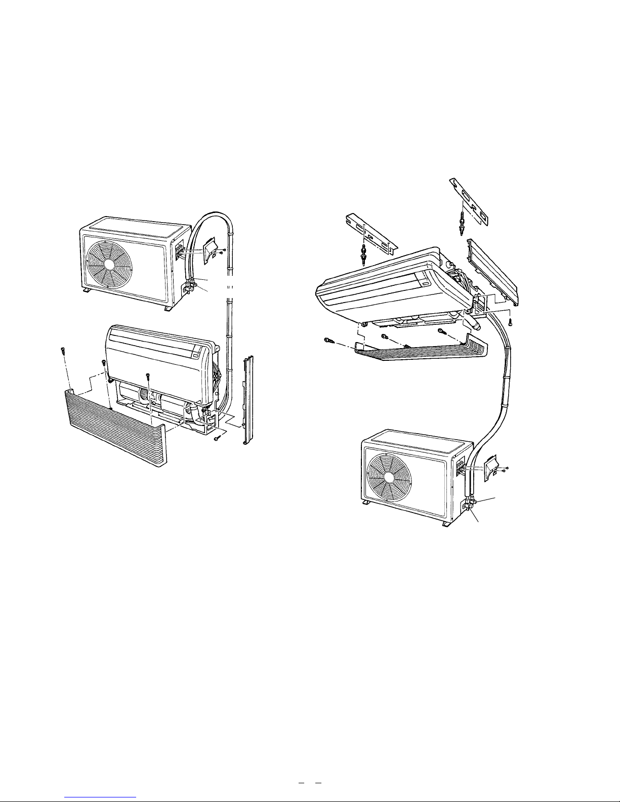
Fig. 1-A Fig. 1-B
Outdoor Unit
3/8” (9.53 mm) dia.
5/8” (15.88 mm) dia.
Indoor Unit
Under ceiling
Indoor Unit
Floor console
Outdoor Unit
3/8”
(9.53 mm) dia.
5/8”
(15.88 mm) dia.
1
Page 3
GENERAL
This INSTALLATION INSTRUCTION SHEET briefly
outlines where and how to install the air conditioning
system. Please read over the entire set of instructions
for the indoor and outdoor units and make sure all
accessory parts listed are with the system before
beginning.
1. TYPE OF COPPER PIPE AND INSULATION
MATERIAL
Copper tubing for connecting the outdoor unit to the
indoor unit and insulation material is available for purchase locally. When you purchase them, please specify the following.
(1)
Deoxidized annealed copper pipe for refrigerant piping as:
Table 1
Outer diameter Thickness
Small pipe 3/8” (9.52 mm) 1/32” (0.8 mm)
Large pipe 5/8” (15.88 mm) 3/64” (1.0 mm)
Cut each pipe to the appropriate length +12” (30 cm)
to 16” (40 cm) to dampen vibration between units.
2. ADDITIONAL MATERIALS REQUIRED FOR
INSTALLATION
(1) Refrigeration (armored) tape
(2) Insulated staples or clamps for connecting wire
(See your local electrical codes.)
(3) Putty
(4) Refrigeration lubricant
(5) Clamps or saddles to secure refrigerant piping
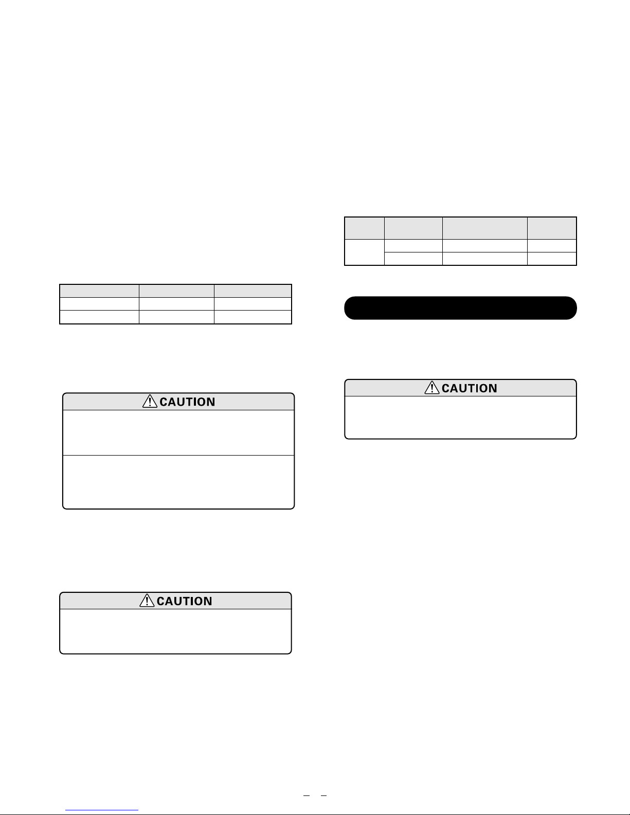
3. OPERATING RANGE
Table 2
Indoor Outdoor
air intake air intake
Cooling
Temperature
Maximum 90°F DB, 73°F WB 115°F DB
Minimum 65°F DB, 57°F WB 70°F DB
ELECTRICAL REQUIREMENT
Always make the air conditioner power supply a special branch circuit and provide a special switch and
receptacle. Do not extend the power cord.
(1) Limit the height difference between
the indoor and outdoor units to
within 26 ft. (8 m).
(2) The maximum length of the piping
is 66 ft. (20 m). If the units are further apart than this, correct operation can not be guaranteed.
(2)
Foamed polyethylene insulation for copper pipes as
required to precise length of piping. Wall thickness of
the insulation should not be less than 5/16” (8 mm).
(3) Use insulated copper wire for field wiring.
Check local electrical codes and regulations before obtaining wire. Also , check
any specified instructions or limitations.
MINIMUM CIRCUIT AMPACITY 15A
MAXIMUM OVERCURRENT PROTECTION 20A
(TIME DELAY FUSE OR HACR TYPE CIRCUIT BREAKER)
2
Page 4
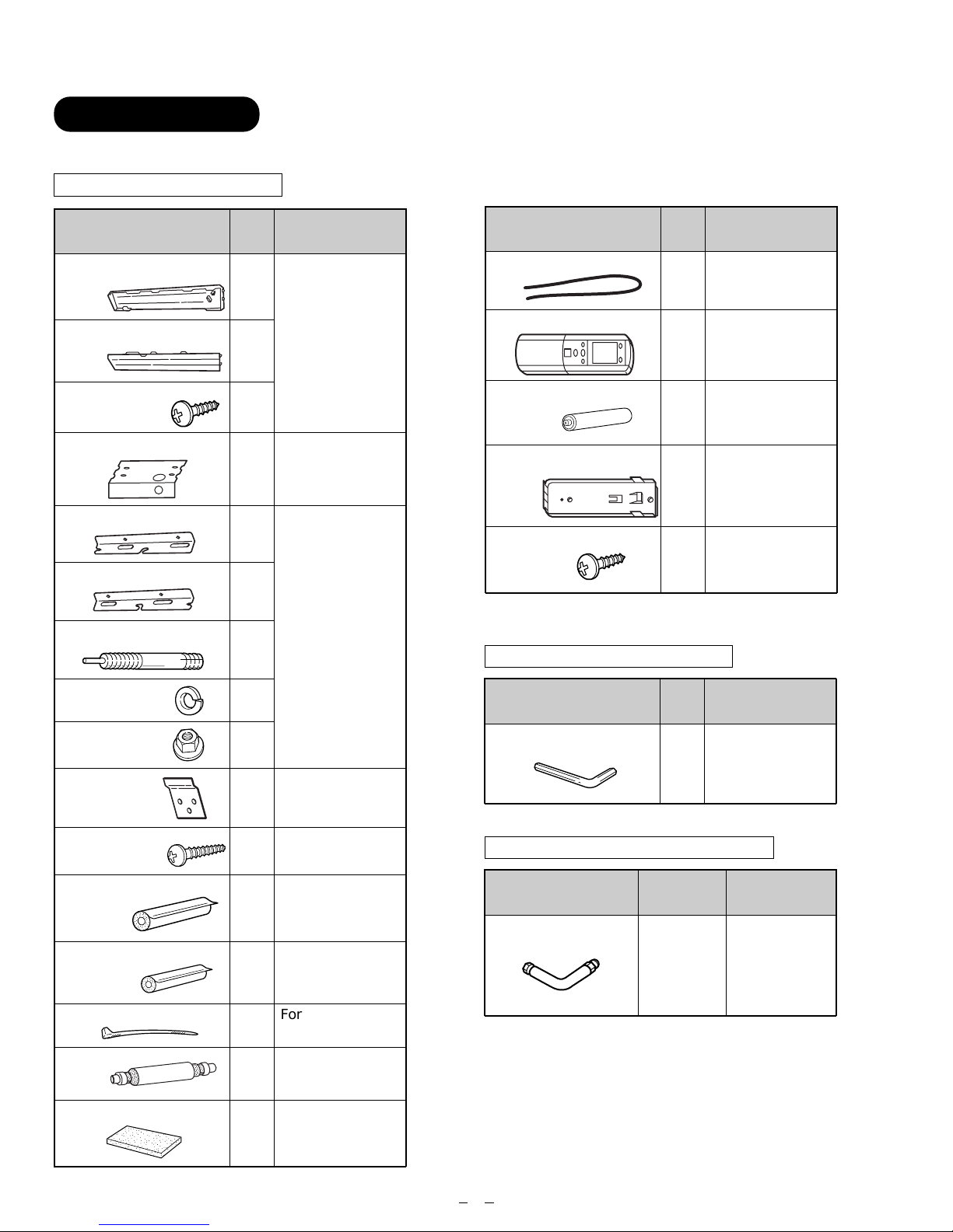
STANDARD PARTS
The following installation parts are furnished. Use them as required.
INDOOR UNIT ACCESSORIES
Name and Shape
Cover plate (left)
Cover plate (right)
Tapping screw
(ø4 x 10)
Installation template
Bracket (left)
Bracket (right)
Anchor bolt (M12)
Q’ty
1
1
2
1
1
1
4
Application
For positioning the
indoor unit
For under ceiling type.
For suspending
the indoor unit
from ceiling
Name and Shape
VT wire
Remote control unit
Battery (penlight)
Remote control unit
holder
Tapping screw
(ø3 x 12)
Q’ty
For fixing the drain
1
hose L 280 mm
Use for air conditioner operation
1
For remote
control unit
4
For mounting the
remote control
1
unit
For remote
control unit holder
2
installation
OUTDOOR UNIT ACCESSORIES
Application
Spring washer
Spring nut
Wall bracket
Tapping screw
(ø4 x 20)
Coupler heat insulator
(large)
Coupler heat insulator
(small)
Nylon fastener
Drain hose
Insulation (drain hose)
4
4
For suspending the
2
indoor unit on the
wall.
For fixing the wall
6
bracket.
For indoor side
pipe joint
1
(Large pipe)
For indoor side
1
pipe joint
(small pipe)
For fixing the
1
drain hose
1
Adhesive type
70 x 230
1
Name and Shape
Hexagon wrench
Q’ty
Application
For air purge
1
OPTIONAL PARTS FOR INDOOR UNIT
Name and Shape
Joint pipe-A For indoor
Part No.
9302812021
Application
side pipe joint
3
Page 5
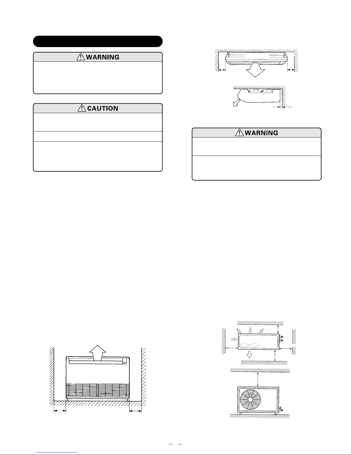
SELECTING THE MOUNTING POSITION
• Under ceiling
Ceiling
Install at a place that can withstand the
weight of the indoor and outdoor units
and install positively so that the units
will not topple or fall.
(1) Do not install where there is the
danger of combustible gas leakage.
(2) Do not install near heat sources.
(3) If children under 10 years old may
approach the unit, take preventive
measures so that they cannot reach
the unit.
Decide the mounting position with the customer as follows:
1. INDOOR UNIT
(1) Install the indoor unit level on a strong wall, floor,
ceiling which is not subject to vibration.
(2) The inlet and outlet ports should not be obstructed :
the air should be able to blow all over the room.
(3) Install the unit near an electric outlet or special
branch circuit.
(4) Do not install the unit where it will be exposed to
direct sunlight.
(5) Install the unit where connection to the outdoor unit
is easy.
(6) Install the unit where the drain pipe can be easily
installed.
(7) Take servicing, etc. into consideration and leave the
spaces shown in Fig.2. Also install the unit where
the filter can be removed.
Left
6” (15 cm)
or more
Indoor unit
Ceiling
12” (30 cm)
or more
3/4” (2 cm) or more
Right
2. OUTDOOR UNIT
(1) Install the unit where it will not be
tilted by more than 5˚
(2) When installing the outdoor unit
where it may be exposed to strong
wind, fasten it securely .
(1) If possible, do not install the unit where it will be
exposed to direct sunlight. (If necessary, install a
blind that does not interfere with the air flow.)
(2) Install the outdoor unit in a place where it will be
free from being dirty or getting wet by rain as much
as possible.
(3) Install the unit when connection to the indoor unit is
easy.
(4) Do not place animals and plants in the path of the
warm air.
(5) Take the air conditioner weight into account and
select a place where noise and vibration are small.
(6) Select a place so that the warm air and noise from
the air conditioner do not disturb neighbors.
(7)
Provide the space shown in Fig. 2 so that the air flow is
not blocked. Also for efficient operation, leave open
three of the four directions front, rear and both sides.
Fig. 2
• Floor console
Left Right
12” (30 cm)
or more
12” (30 cm)
or more
Fig. 3
1’ (30 cm)
or more
1’4” (40 cm) or more
1’ (30 cm)
or more
2’ (60 cm)
or more
4
2’ (60 cm)
or more
Page 6
INSTALLATION PROCEDURE
Install the room air conditioner as follows:
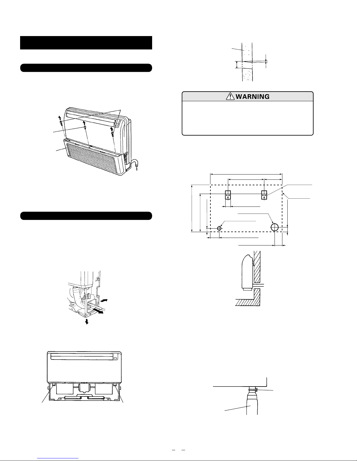
1.
PREPARING INDOOR UNIT INSTALLATION
1. REMOVE THE INTAKE GRILLE
Open the intake grille and remove the three screws.
(Fig. 4)
Fig. 7
Wall
4” (100 mm)
Indoor side
1/4” (6 mm)
Outdoor side
Fig. 4
Screw
Intake grille
Tapping screw
Remark : The main unit can be wired before
the indoor unit is installed. Select the
most appropriate installation order.
2. INDOOR UNIT INSTALLATION
A. FLOOR CONSOLE TYPE
1. DRILLING FOR PIPING
Select piping and drain directions. (Fig. 5)
The piping and drain can be made in three directions a
shown below.
Fig. 5
Avoid areas where electrical wiring or
conduits are located.
Accidentally cutting a live wire can cause
death or injury.
When installing the set to wall, install the accessory
wall bracket at the position shown in Fig. 8, and
mount the set to it.
Fig. 8
26" (65.5 cm)
21" (53 cm)
1-3/4" (4.5 cm)
39" (99 cm)
20" (50 cm)
2-1/2" (6.5 cm)
4" (10 cm) hole
2" (5 cm) hole
5" (12.5 cm)
4" (10 cm)
9-5/8"
(24.5 cm)
Wall bracket
Side of set
2-1/2" (6.5 cm)
The drain hose can be connected to either the left or
right side. (Fig. 6)
Fig. 6
Drain hose (Left side)
When the directions are selected, drill a 4” (10cm) dia.
hole on the wall so that the hole is tilted downward
toward the outdoor for smooth water flow. When the
pipe is led out from the rear, make a hole in Fig. 7, at
the position shown.
Drain hose (Right side)
2. INSTALLING DRAIN HOSE
INSTALL THE DRAIN HOSE
Select whether the drain hose will be connected to the
left or right side. (Fig. 6)
Insert the drain hose into drain pan, then secure the
drain hose with a nylon fastener. (Fig. 9)
Fig. 9
Drain pan
Nylon fastener
Drain hose
5
Page 7

Wrap the insulation(drain hose)around the drain hose
connection. (Fig. 10)
Fig. 10
Drain pan
Insulation
(Drain hose)
1. DRILLING FOR PIPING
Select piping and drain directions. (Fig.14)
Fig. 14
Top
Rear
(Install the drain hose
in this direction.)
Drain hose
Be sure to arrange the drain hose so that it is leveled
lower than the drain hose connecting port of the
indoor unit.
Fig. 11
Arrange the drain hose
lower than this portion
OK
NO
Drain hose
NO
Do not install the unit so that the drain
hose side is too high. Height A should
be less than 5 mm. (Fig. 12)
Fig. 12
Drain hose
A
BAD
A
BAD
Right
Install the drain hose at the rear; it
should not be installed on the top or
right side.
When the directions are selected, drill 3-1/8” (80 mm)
and 2”(50 mm) or 6”(150 mm) dia. hole on the wall so
that the hole is tilted downward toward the outdoor
for smooth water flow.
Fig. 15
2. DRILLING HOLES FOR ANCHOR BOLTS AND
INSTALLING THE ANCHOR BOLTS.
With a concrete drill, drill four 1/2 “(12.7 mm)dia
holes. (Fig. 16)
Fig. 16
Wall
Indoor side
1/4” (6 mm)
Outdoor side
B. UNDER CEILING TYPE
Using the installation template, drill holes for piping
and anchor bolts(for holes). (Fig. 13)
Fig.13
35.4” (900 mm)
7-7/8”
(200 mm)
Installation
template
Drilling position
for piping
Drilling position
for anchor bolt
Ceiling
Wall
2-3/8” to 2-3/4”
(60 to 70 mm)
ø1/2” (12.7 mm)
Insert the anchor bolts into the drilled holes, and drive
the pins completely into the anchor bolts with a hammer. (Fig. 17)
Fig. 17
6
Page 8

3. INSTALLING BRACKETS
Install the brackets with nuts, washers and spring
washers. (Fig. 18)
Fig. 18
Fig. 21
Arrange the drain hose
lower than this portion.
OK
Remove the hole cover.
Drain hose
NO
Spring washer
Special nut
Bracket (Left)
Bracket
Bracket (Right)
4. INSTALLING INDOOR UNIT
Reset the hex bolts as shown in Fig.19.
Fig. 19
Hex bolt
Indoor unit
5/16” to 1/2”
(8 to 1 3mm)
Apply the indoor unit to the brackets.(Fig. 20)
Fig. 20
When drain hose is arranged backward. Secure the
drain hose with the VT wire. (Fig. 22)
Fig. 22
Piping hole
VT wire
hole
Pass the drain hose
through here.
Base (Bottom)
Intake
grille
Cut the grille
Drain hose
VT wire
3. OUTDOOR UNIT INSTALLATION
• When the outdoor unit will be exposed to strong
wind, fasten it with bolts at the places indicated by
the arrows. (Fig. 23)
Fig. 23
Bolt
Indoor unit
Bracket
Now, securely tighten the hex bolts in both sides.
5. INSTALL THE DRAIN HOSE
Select whether the drain hose will be connected to the
left or right side. (Fig. 6)
Insert the drain hose into the drain pan, then secure
the drain hose with a nylon fastener. (Fig. 9)
Wrap the insulation (drain hose) around the drain
hose connection. (Fig. 10)
Be sure to arrange the drain hose so that it is leveled
lower than the drain hose connecting port to the
indoor unit. (Fig. 21)
Bottom
7
Page 9

4. CONNECTING THE PIPING
1. FLARE PROCESSING
(1) Cut the connection pipe with pipe cutters so that the
pipe is not deformed.
(2) Holding the pipe downward so that cuttings cannot
enter the pipe and remove the burrs.
(3) Remove the flare nut from the indoor unit pipe and
outdoor unit and assemble as shown in (Table 3)
and insert the flare nut onto the pipe, and flare with
a flaring tool.
(4) Check if the flared part “L”(Fig. 24) is spread uni-
formly and that there are no cracks.
Table 3
Pipe Flare nut
Small pipe Small (width across flats 7/8” (22mm))
Large pipe Large (width across flats 31/32” (24mm))
Do not bend the pipes in an angle more than 90°.
When pipes are repeatedly bent or stretched, the
material will harden, making it difficult to bend or
stretch them any more. Do not bend or stretch the
pipes more than three times.
When bending the pipe, do not bend it as is. The pipe
will be collapsed. In this case, cut the heat insulating
pipe with a sharp cutter as shown in Fig. 26, and bend
it after exposing the pipe. After bending the pipe as
you want, be sure to put the heat insulating pipe back
on the pipe, and secure it with tape.
Fig. 26
Heat insulating
pipe
Cutter
Cut line
Pipe
Fig. 24
Width across flats
L dimension
Small pipe 3/8”(9.53 mm) dia.
Large pipe 5/8” (15.88 mm) dia.
5/64” (1.8 to 2.0 mm)
3/32” (2.2 to 2.4 mm)
2. BENDING PIPES
The pipes are shaped by your hands. Be careful not to
collapse them.
Fig. 25
Extend the pipe
OK
by unwinding it.
NO
3. CONNECTION PIPES
(1) Indoor unit side
Centering the pipe against port on the indoor unit,
turn the flare nut with your hand. (Fig. 27)
Be sure that the small pipe is completely installed
before connecting the large the pipe.
Fig. 27
Indoor unit side
Optional parts
Be sure to apply the pipe against the
port on the indoor unit correctly. If the
centering is improper, the flare nut cannot be tightened smoothly. If the flare
nut is forced to turn, the threads will be
damaged.
8
Page 10

When the flare nut is tightened properly by your hand,
use a torque wrench to finally tighten it.
Fig. 28
Tighten with two wrenches.
Wrench (fixed)
Torque
wrench
Indoor unit
pipe
Flare nut
Connection pipe
To prevent gas leakage,
coat the flare surface with
refrigerator oil.
4. CHECKING THE PIPE CONNECTIONS FOR
GAS LEAKING
For both the indoor and outdoor unit sides, check the
joints for gas leaking by the use of a gas leakage
detector without fail when the pipes are connected.
5. HEAT INSULATION ON THE PIPE JOINTS
(INDOOR SIDE ONLY)
Put coupler heat insulator on the joints (indoor side
only) (Fig. 30).
Table 4 Flare nut tightening torque
Pipe Tightening torque
Small pipe
Large pipe
22.42 to 25.32 ft. lbs
(310 to 350 kgf •cm)
54.25 to 57.86 ft. lbs
•
(750 to 800 kgf
cm)
Do not remove the cap from the connection pipe
before connecting the pipe.
Be sure to connect the large pipe after
connecting the small pipe completely .
(2) Outdoor unit side
Tighten the flare nut of the connection pipe at the
outdoor unit valve connector. The tightening
method is the same as that as at the indoor side.
Fig. 29
Connection pipe
Fig. 30
No gap
Coupler heat
insulation (large)
Coupler heat
insulation
Indoor unit
Large pipe
Small pipe
Coupler heat
insulation
(small)
Be sure to overlap
the insulation
}
No gap
5. GAS LEAKAGE INSPECTION
After connecting the piping, check the
joints for gas leakage with gas leak
detector .
(Large pipe)
3-way valve
(Small pipe)
Flare nut
Pipe coupling
2-way valve
9
Page 11

6. VACUUM PROCESS
7.
HOW TO CONNECT WIRING TO THE TERMINALS
1. VACUUM
(1) Remove the cap, and connect the gauge manifold
and the vacuum pump to the charging valve by the
service hoses.
(2)
Vacuum the indoor unit and the connecting pipes until
the pressure in them lowers to below 1.5 mmHg.
(3) Disconnect the service hoses and fit the cap to the
charging valve (Tightening torque : 70 to 90 kgf
•
cm).
(4) Remove the blank caps, and fully open the spindles
of the 2-way and 3-way valves with a hexagon
wrench (Torque : 2-way valve : 70 to 90 kgf
3-way valve : 100 to 120 kgf
•
cm).
•
(5) Tighten the blank caps of the 2-way valve and 3-way
valve to the specified torque (200 to 250 kgf
•
cm).
Fig. 31
Outdoor
unit
Service hose
with valve
core
Refrigerant pipe
Cap
3-way valve
Blank cap
Charging
valve
Gauge
manifold
Service hose
Vacuum
pump
2. ADDITIONAL CHARGE
Refrigerant suitable for a piping length of 5 m is
charged in the outdoor unit at the factory.
When the piping is longer than 5 m, additional charging is necessary.
For the additional amount, see the table below.
Table 5
Pipe length
Additional
refrigerant
25 ft 33 ft 49 ft 66 ft
(7.5 m) (10 m) (15 m) (20 m)
None
2.1 oz 4.2 oz 6.3 oz
(60 g) (120 g) (180 g)
cm,
A. For solid core wiring (or F-cable)
(1) Cut the wire end with a wire cutter or wire cut-
ting pliers, then strip the insulation to about
15/16” (25 mm) to expose the solid wire.
(2) Using a screwdriver, remove the terminal screw
(s) on the terminal board.
(3) Using pliers, bend the solid wire to form a loop
suitable for the terminal screw.
(4) Shape the loop wire properly, place it on the ter-
minal board and tighten securely with the terminal screw using a screwdriver.
B. For strand wiring
(1) Cut the wire end with a wire cutter or wire cut-
ting pliers, then strip the insulation to about 3/8”
(10 mm) to expose the strand wiring.
(2) Using a screwdriver, remove the terminal screw
(s) on the terminal board.
(3)
Using a round terminal fastener or pliers, securely
clamp a round terminal to each stripped wire end.
(4)
Position the round terminal wire, and replace and
tighten the terminal screw with a screwdriver.
Fig. 32
Solid wire Strand wire
Round terminal
Loop
Strip 15/16”
(25 mm)
Insulation
Wire
Screw with
special washer
Round
terminal
Terminal block
Terminal
board
Strip 3/8”
(10 mm)
Screw with
special washer
Round
terminal
Wire
Between 5 m and 20 m, when using a connection pipe
other than that shown in the table, charge additional
refrigerant with 0.42 oz (12g) / 3.3 ft (1 m) as the criteria.
(1) Always pump down the piping
before use.
(2) Add refrigerant from the charging
valve after the completion of the
work.
10
Page 12

8. ELECTRICAL WIRING
(1) Match the terminal block numbers
and connection cord colors with
those of the outdoor unit. Erroneous
wiring may cause burning of the
electric parts.
(2) Connect the connection cords firmly
to the terminal block. Imperfect
installation may cause a fire.
(3) Always fasten the outside covering
of the connection cord with the cord
clamp. (If the insulator is chafed,
electric leakage may occur.)
(4) Always connect the ground wire.
1. INDOOR UNIT SIDE
(1) Remove the electric component box.
Fig. 33
2.
Pull out the electric component box.
Fig. 35
Electric component box
(3) Remove the electric component box cover.
Fig. 36
Fig. 34
Electric component box
Remove the four
tapping screws.
Base
Electric component box cover
Remove the three tapping screws.
Electric component box
Be careful not to pinch the lead wires
between the electric component box and
base.
Do not remove the screws. If the stays
are removed, the electric component box
will fall.
11
Page 13

(4) Wiring
q Process the end of the connection cords to the
dimensions shown in Fig. 37.
w Connect the end of the connection cord fully into the
terminal block.
Fig. 37
2. OUTDOOR UNIT SIDE
A. To take off the panel (top), remove the 2 screws.
B. Dismount the plugs on the conduit plate.
C. Temporarily mount the conduit tubes on the con-
duit plate.
D. Properly connect both the power supply and inter-
unit lines to the corresponding terminals on the terminal board.
Refer to the wiring system diagram in Fig. 41
[Which also appears on the panel (top)].
E. Ground the unit in accordance with local codes.
F. Be sure to size each wire allowing several inches
longer than the required length for wiring.
G. Use lock nuts to secure the conduit tube.
Fig. 39
Connection cord
e Fasten the end of the connection cord with the
screw.
(5) Floor console / Under ceiling select switch
q The electrical circuits for this were set for use as a
ceiling type at the factory.
w The following changes must be made to the set-
tings if the unit is to be used as a floor type.
e Changing the settings for the electrical circuits.
Switch 1 (SW1) on the printed circuit board inside
the electric component box must be set as follows.
Fig. 38
SW1
Lock nut
Panel (top)
Conduit plate
Power supply
Inter-unit line
Plug
■ EXAMPLE OF INCORRECT WIRING
(Cooling model)
The following are examples of improper
wiring that results in system misoperation. You should confirm that you have
wired the units correctly before beginning the test run.
Microcomputer
SW1
Under ceiling type
Floor console type
SW1
12
Page 14

Fig. 40
Problem 1
• Short circuit will occur after approx.
3 minutes and the power circuit fuse blows.
Disconnect
(A)
switch
Grounding line
Indoor unit
Outdoor unit
Problem 2
• Air conditioner will not operate.
Disconnect
(B)
switch
Grounding line
Indoor unit
Outdoor unit
Disconnect
(C)
switch
Grounding line
Indoor unit
Outdoor unit
Problem 3
•
Compressor will not start; only indoor unit will operate.
(D)
Disconnect
switch
(E)
Disconnect
switch
9. POWER
(1) The rated voltage of this product is
230/208V A.C. 60Hz.
(2) Before turning on the verify that the
voltage is within the 187V to 253 V
range.
(3) Always use a special branch circuit
and install a special receptacle to
supply power to the air conditioner.
(4) Use a circuit breaker and receptacle
matched to the capacity of the air
conditioner .
(5) The circuit breaker is installed in the
permanent wiring. Always use a circuit that can trip all the poles of the
wiring and has an isolation distance
of at least 3 mm between the contacts of each pole.
(6) Perform wiring work in accordance
with standards so that the room air
conditioner can be operated safely
and positively.
Grounding line
Indoor unit
Outdoor unit
Grounding line
Indoor unit
Outdoor unit
NOTE
• Connector trade size for this unit is 1/2”. The connector can be bought at a hardware store. Refer to
“How to connect wiring to the terminals” for
instructions on connecting depending on the wire
type you are using.
• The fuse located in the outdoor unit provides
power supply protection and may blow when
power is applied if the system has been incorrectly
wired.
Fig. 41 WIRING SYSTEM DIAGRAM
INDOOR
INDOOR UNIT
Terminal
Disconnect
switch
(Field supply)
14WG
(Inter-unit)
Power lines
230/208 V
230/208 V
230/208 V
OUTDOOR UNIT
Terminal
Fuse
Power supply line
Single-phase, 230/208 V
14AWG
(7) Install a leakage circuit breaker in
accordance with the related laws
and regulations and electric company standards.
(1) The power source capacity must be
the sum of the room air conditioner
current and the current of other electrical appliances. When the current
carrying capacity is insufficient,
change the circuit capacity .
(2) When the voltage is low and the air
conditioner is difficult to start, contact the power company to have the
voltage raised.
Grounding
line
13
Page 15

10.
JM1
JM2
JM3
JM1
JM2
JM3
AUTO RESTART
REMOTE CONTROL 2
REMOTE CONTROL 1
ABCD
REMOTE CONTROL UNIT INSTALLATION
(1) Check that the indoor unit correctly
receives the signal from the remote
control unit, then install the remote
control unit holder.
Select the remote control unit holder
(2)
selection site by paying careful attention
to the following: Avoid places in direct
sunlight. Select a place that will not be
affected by the heat from a stove, etc.
1. REMOTE CONTROL UNIT HOLDER
INSTALLATION
• Install the remote control unit so that the front is facing the photocell. (Fig. 42)
Fig. 42
2. REMOTE CONTROL UNIT CODE SWITCHING
Fig. 44
Indoor unit
Printed circuit board
Remote control unit
Photocell
Remote control unit
• Install the remote control unit with a distance of 7m
between the remote control unit and the photocell
as the criteria. However, when installing the remote
control unit, check that it operates positively.
• Install the remote control unit holder to a wall, pillar,
etc. with the tapping screw. (Fig. 43)
Fig. 43
For use as Handy Type
Insert
Screws
q Mount the Holder.
For use as Wall Fixing Type
Screws
q Mount the Holder.
w Set the Remote
Control Unit.
Insert
w Set the Remote
Control Unit.
Slide up
Screws
e To remove the
Remote Control
Unit (when use
at hand.)
Slide
e Attach the unit
to the holder as
shown.
14
ACL button
Remote control unit signal
selector switch
If the jumper wires (JM2 and JM3) are installed onto
the control panel, the signal can be adjusted using the
remote control unit signal selector switch.
Table 6
Jumper wire
JM 2 JM 3
Connect Connect
Remote control unit
signal selector switch
A (Primary setting)
Connect Disconnect B
Disconnect Connect C
Disconnect Disconnect D
After setting the remote control unit signal selector
switch, press the ACL button.
Page 16

11. TEST RUNNING
1. REMOTE CONTROL
• Press the remote control unit test run button while
the air conditioner is running.
• At the end of test running, press the remote control
unit start/stop button. (Fig. 45)
Fig. 45
START/STOP
button
TEST RUN
button
• Run the air conditioner in accordance with the operating manual.
Fig. 46
OPERATION lamp (Red)
TIMER lamp (Green)
SWING lamp (Orange)
SWING lamp (Orange)
Operation can be checked by lighting and flashing of
the display section OPETATION and TIMER lamps.
Perform judgement in accordance with the following.
Table 7
Error display Error contents
ON
OPERATION
LAMP
OFF
ON
TIMER
LAMP
OFF
ON
OPERATION
LAMP
OFF
ON
TIMER
LAMP
OFF
0.5 sec
0.1 sec
0.1 sec
0.5 sec
0.1 sec
0.1 sec
5 sec
5 sec
0.5 sec
Two quick
flashes
repeated
0.1sec
ON/OFF
repeated
0.5 sec
Three quick
flashes
repeated
0.1sec
ON/OFF
repeated
Room temperature
thermistor abnormal
temperature detected
Piping thermistor
abnormal
temperature detected
CHECK ITEMS
1. INDOOR UNIT
(1) Is operation of each button on the remote control
unit normal?
(2) Does each lamp light normally?
(3) Do not air flow direction louvers operate normally?
(4) Is the drain normal?
(5) Is there any abnormal noise and vibration during
operation?
2. OUTDOOR UNIT
(1) Is there any abnormal noise and vibration during
operation?
(2) Will noise, wind, or drain water from the unit disturb
the neighbors?
(3) Is there any gas leakage?
• Do not operate the air conditioner in the test running state for a long time.
• For the operation method, refer to the operating
manual and perform operation check.
• Test running
When the air conditioner is run by pressing the
remote control unit test run button, the OPERATION
and TIMER lamps flash slowly at the same time.
• Error
The OPERATION and TIMER lamps operate as follows (Table 7) according to the error contents.
15
Page 17

12. FRESH AIR INTAKE
• Open the hole and connect the duct. (Fig. 47)
Fig. 47
3. MOUNT THE INTAKE GRILLE
(1) Cut the right side of the intake grille. This is only
when the pipe exits from the right side. (Fig. 51)
Fig. 51
Rear side
Duct
13. MOUNT THE COVER PLATE AND
THE INTAKE GRILLE
1. MOUNT THE COVER PLATE (RIGHT)
(1)
Cut a pipe exit hole in the right plate. This is only when
the pipe exits from the right side. (This operation is not
required when the protrusion is on the top or rear.)
Fig. 48
(2) Join the cover plates (right) and mount with screws.
(Fig. 49)
Cover plate(Right)
Fig. 49
(2) Insert the hinges on the bottom of the intake grille
into the holes in the base assembly. Then mount the
arms to the three areas on the top of the intake
grille. (Fig. 52)
Fig. 52
2. MOUNT THE COVER PLATE (LEFT)
(1) Join the cover plates (left) and mount with screws.
Fig. 50
Cover plate (left)
16
Page 18

353 Rt. 46 W.
Fairfield, NJ 07004
888-888-FGAI
www.fujitsugeneral.com
June 2000
 Loading...