

Page 1
ServerView Resource Orchestrator
Virtual Edition V3.1.1
User's Guide
Windows/Linux
J2X1-7606-05ENZ0(01)
January 2013
Page 2
Preface
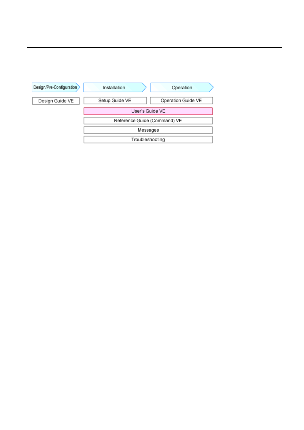
Resource Orchestrator Documentation Road Map
The documentation road map for Resource Orchestrator is as shown below.
Resource Orchestrator Documentation Road Map
For information about the documents for Resource Orchestrator, refer to "Chapter 1 Documentation Road Map" in the "Design Guide
VE".
Purpose
This manual provides an outline of the operation method of the ROR console provided by ServerView Resource Orchestrator (hereinafter
Resource Orchestrator).
Target Readers
This manual is written for people who will install Resource Orchestrator.
When setting up systems, it is assumed that readers have the basic knowledge required to configure the servers, storage, and network
devices to be installed.
Organization
This manual is composed as follows:
Chapter 1 Login and Logout
Explains how to log in and out of the ROR console.
Chapter 2 Home
Explains the ROR Console Home window display.
Chapter 3 Resource Management Overview
Provides an overview of the two views available in Resource Orchestrator.
Chapter 4 License Setup and Confirmation
Explains license setup.
Chapter 5 Managing User Accounts
Explains how to register, modify, and delete user accounts.
Chapter 6 BladeViewer
Provides an overview of BladeViewer and explains its features.
Chapter 7 Registering Resources
Explains how to register the resources used by Resource Orchestrator.
Chapter 8 Changing Admin Server Settings
Explains how to change the settings of the admin server.
- i -
Page 3

Chapter 9 Changing Resources
Explains how to change settings for the admin server or resources registered on the admin server.
Chapter 10 Configuring the Operating Environments of Managed Servers
Explains how to install software to the registered managed servers and set up their operating environment.
Chapter 11 Deleting Resources
Explains how to delete resources.
Chapter 12 Pre-configuration for Resource Registration and Modification
Provides an overview of the pre-configuration function and explains how to use system configuration files.
Chapter 13 Network Map
Provides an overview of the Network Map and explains its features.
Chapter 14 Power Control
Explains how to remotely control the power state of managed resources.
Chapter 15 Control of VM Environments
Explains the features specific to VM guests and VM hosts.
Chapter 16 Backup and Restore
Explains how to use the backup and restore functions provided in Resource Orchestrator.
Chapter 17 Cloning [Physical Servers]
Explains how to use the server cloning function.
Chapter 18 Server Switchover Settings
Explains the settings and usage of the server switchover function.
Chapter 19 Collecting Power Consumption Data and Displaying Graphs
Explains how to export the power consumption data collected from registered power monitoring targets and how to display it as graphs,
and also describes the exported data's format.
Appendix A User Interface
Provides an overview of the ROR console GUI.
Appendix B Format of CSV System Configuration Files
Explains the format of the CSV system configuration files used by Resource Orchestrator's pre-configuration function.
Appendix C Maintenance Mode
Explains the maintenance mode available in Resource Orchestrator and how to use it.
Glossary
Explains the terms used in this manual. Please refer to it when necessary.
Notational Conventions
The notation in this manual conforms to the following conventions.
- When using Resource Orchestrator and the functions necessary differ due to the necessary basic software (OS), it is indicated as
follows:
[Windows Manager]
Sections related to Windows manager
[Linux Manager] Sections related to Linux manager
[Windows] Sections related to Windows (When not using Hyper-V)
[Linux] Sections related to Linux
- ii -
Page 4

[Red Hat Enterprise Linux] Sections related to Red Hat Enterprise Linux
[Solaris] Sections related to Solaris
[VMware] Sections related to VMware
[Hyper-V] Sections related to Hyper-V
[Xen] Sections related to Xen
[KVM] Sections related to RHEL-KVM
[Solaris Zones] Sections related to Solaris zones
[OVM for x86] Sections related to Oracle VM Server for x86
[OVM for SPARC] Sections related to Oracle VM Server for SPARC
[Physical Servers] Sections related to physical servers
[VM host]
Sections related to VMware, Windows Server 2008 with Hyper-V enabled,
Xen, RHEL-KVM, Solaris zones, and OVM for SPARC
- Unless specified otherwise, the blade servers mentioned in this manual refer to PRIMERGY BX servers.
- Oracle Solaris may also be indicated as Solaris, Solaris Operating System, or Solaris OS.
- Oracle Solaris Zones may also be indicated as Solaris Containers or Solaris Container.
- Oracle VM Server for x86 may also be indicated as Oracle VM.
- In Resource Orchestrator the following servers are referred to as SPARC Servers/SPARC Enterprise.
- SPARC Enterprise M3000/M4000/M5000/M8000/M9000
- SPARC Enterprise T5120/T5140/T5220/T5240/T5440
- SPARC M10-1/M10-4/M10-4S
- References and character strings or values requiring emphasis are indicated using double quotes ( " ).
- Window names, dialog names, menu names, and tab names are shown enclosed by brackets ( [ ] ).
- Button names are shown enclosed by angle brackets (< >) or square brackets ([ ]).
- The order of selecting menus is indicated using [ ]-[ ].
- Text to be entered by the user is indicated using bold text.
- Variables are indicated using italic text and underscores.
- The ellipses ("...") in menu names, indicating settings and operation window startup, are not shown.
- The ">" used in Windows is included in usage examples. When using Linux, read ">" as meaning "#".
- The URLs in this manual were correct when the manual was written.
Menus in the ROR console
Operations on the ROR console can be performed using either the menu bar or pop-up menus.
By convention, procedures described in this manual only refer to pop-up menus.
Regarding Installation Folder Paths
The installation folder path may be given as C:\Fujitsu\ROR in this manual.
Replace it as shown below.
When using Windows 64-bit (x64)
C:\Program Files (x86)\Resource Orchestrator
- iii -
Page 5

When using Windows 32-bit (x86)
C:\Program Files\Resource Orchestrator
Abbreviations
The following abbreviations are used in this manual:
Abbreviation Products
Microsoft(R) Windows Server(R) 2012 Standard
Microsoft(R) Windows Server(R) 2012 Datacenter
Microsoft(R) Windows Server(R) 2008 Standard
Microsoft(R) Windows Server(R) 2008 Enterprise
Microsoft(R) Windows Server(R) 2008 R2 Standard
Microsoft(R) Windows Server(R) 2008 R2 Enterprise
Microsoft(R) Windows Server(R) 2008 R2 Datacenter
Microsoft(R) Windows Server(R) 2003 R2, Standard Edition
Microsoft(R) Windows Server(R) 2003 R2, Enterprise Edition
Windows
Microsoft(R) Windows Server(R) 2003 R2, Standard x64 Edition
Microsoft(R) Windows Server(R) 2003 R2, Enterprise x64 Edition
Windows(R) 8 Pro
Windows(R) 8 Enterprise
Windows(R) 7 Professional
Windows(R) 7 Ultimate
Windows Vista(R) Business
Windows Vista(R) Enterprise
Windows Vista(R) Ultimate
Microsoft(R) Windows(R) XP Professional operating system
Windows Server 2012
Windows Server 2008
Windows 2008 x86 Edition
Windows 2008 x64 Edition
Windows Server 2003
Windows 2003 x64 Edition
Windows 8
Windows 7
Microsoft(R) Windows Server(R) 2012 Standard
Microsoft(R) Windows Server(R) 2012 Datacenter
Microsoft(R) Windows Server(R) 2008 Standard
Microsoft(R) Windows Server(R) 2008 Enterprise
Microsoft(R) Windows Server(R) 2008 R2 Standard
Microsoft(R) Windows Server(R) 2008 R2 Enterprise
Microsoft(R) Windows Server(R) 2008 R2 Datacenter
Microsoft(R) Windows Server(R) 2008 Standard (x86)
Microsoft(R) Windows Server(R) 2008 Enterprise (x86)
Microsoft(R) Windows Server(R) 2008 Standard (x64)
Microsoft(R) Windows Server(R) 2008 Enterprise (x64)
Microsoft(R) Windows Server(R) 2003 R2, Standard Edition
Microsoft(R) Windows Server(R) 2003 R2, Enterprise Edition
Microsoft(R) Windows Server(R) 2003 R2, Standard x64 Edition
Microsoft(R) Windows Server(R) 2003 R2, Enterprise x64 Edition
Microsoft(R) Windows Server(R) 2003 R2, Standard x64 Edition
Microsoft(R) Windows Server(R) 2003 R2, Enterprise x64 Edition
Windows(R) 8 Pro
Windows(R) 8 Enterprise
Windows(R) 7 Professional
Windows(R) 7 Ultimate
Windows Vista
Windows XP
Windows Vista(R) Business
Windows Vista(R) Enterprise
Windows Vista(R) Ultimate
Microsoft(R) Windows(R) XP Professional operating system
- iv -
Page 6

Abbreviation Products
Windows PE Microsoft(R) Windows(R) Preinstallation Environment
Red Hat(R) Enterprise Linux(R) AS (v.4 for x86)
Red Hat(R) Enterprise Linux(R) ES (v.4 for x86)
Red Hat(R) Enterprise Linux(R) AS (v.4 for EM64T)
Red Hat(R) Enterprise Linux(R) ES (v.4 for EM64T)
Red Hat(R) Enterprise Linux(R) AS (4.5 for x86)
Red Hat(R) Enterprise Linux(R) ES (4.5 for x86)
Red Hat(R) Enterprise Linux(R) AS (4.5 for EM64T)
Red Hat(R) Enterprise Linux(R) ES (4.5 for EM64T)
Red Hat(R) Enterprise Linux(R) AS (4.6 for x86)
Red Hat(R) Enterprise Linux(R) ES (4.6 for x86)
Red Hat(R) Enterprise Linux(R) AS (4.6 for EM64T)
Red Hat(R) Enterprise Linux(R) ES (4.6 for EM64T)
Red Hat(R) Enterprise Linux(R) AS (4.7 for x86)
Red Hat(R) Enterprise Linux(R) ES (4.7 for x86)
Red Hat(R) Enterprise Linux(R) AS (4.7 for EM64T)
Red Hat(R) Enterprise Linux(R) ES (4.7 for EM64T)
Red Hat(R) Enterprise Linux(R) AS (4.8 for x86)
Red Hat(R) Enterprise Linux(R) ES (4.8 for x86)
Red Hat(R) Enterprise Linux(R) AS (4.8 for EM64T)
Red Hat(R) Enterprise Linux(R) ES (4.8 for EM64T)
Red Hat(R) Enterprise Linux(R) 5 (for x86)
Red Hat(R) Enterprise Linux(R) 5 (for Intel64)
Red Hat(R) Enterprise Linux(R) 5.1 (for x86)
Red Hat(R) Enterprise Linux(R) 5.1 (for Intel64)
Red Hat(R) Enterprise Linux(R) 5.2 (for x86)
Red Hat(R) Enterprise Linux(R) 5.2 (for Intel64)
Red Hat(R) Enterprise Linux(R) 5.3 (for x86)
Linux
Red Hat(R) Enterprise Linux(R) 5.3 (for Intel64)
Red Hat(R) Enterprise Linux(R) 5.4 (for x86)
Red Hat(R) Enterprise Linux(R) 5.4 (for Intel64)
Red Hat(R) Enterprise Linux(R) 5.5 (for x86)
Red Hat(R) Enterprise Linux(R) 5.5 (for Intel64)
Red Hat(R) Enterprise Linux(R) 5.6 (for x86)
Red Hat(R) Enterprise Linux(R) 5.6 (for Intel64)
Red Hat(R) Enterprise Linux(R) 5.7 (for x86)
Red Hat(R) Enterprise Linux(R) 5.7 (for Intel64)
Red Hat(R) Enterprise Linux(R) 5.8 (for x86)
Red Hat(R) Enterprise Linux(R) 5.8 (for Intel64)
Red Hat(R) Enterprise Linux(R) 6 (for x86)
Red Hat(R) Enterprise Linux(R) 6 (for Intel64)
Red Hat(R) Enterprise Linux(R) 6.1 (for x86)
Red Hat(R) Enterprise Linux(R) 6.1 (for Intel64)
Red Hat(R) Enterprise Linux(R) 6.2 (for x86)
Red Hat(R) Enterprise Linux(R) 6.2 (for Intel64)
Red Hat(R) Enterprise Linux(R) 6.3 (for x86)
Red Hat(R) Enterprise Linux(R) 6.3 (for Intel64)
SUSE(R) Linux Enterprise Server 10 Service Pack 2 for x86
SUSE(R) Linux Enterprise Server 10 Service Pack 2 for EM64T
SUSE(R) Linux Enterprise Server 10 Service Pack 3 for x86
SUSE(R) Linux Enterprise Server 10 Service Pack 3 for EM64T
SUSE(R) Linux Enterprise Server 11 for x86
SUSE(R) Linux Enterprise Server 11 for EM64T
SUSE(R) Linux Enterprise Server 11 Service Pack 1 for x86
SUSE(R) Linux Enterprise Server 11 Service Pack 1 for EM64T
Oracle Enterprise Linux Release 5 Update 4 for x86 (32 Bit)
- v -
Page 7

Abbreviation Products
Red Hat Enterprise Linux
Oracle Enterprise Linux Release 5 Update 4 for x86_64 (64 Bit)
Oracle Enterprise Linux Release 5 Update 5 for x86 (32 Bit)
Oracle Enterprise Linux Release 5 Update 5 for x86_64 (64 Bit)
Red Hat(R) Enterprise Linux(R) AS (v.4 for x86)
Red Hat(R) Enterprise Linux(R) ES (v.4 for x86)
Red Hat(R) Enterprise Linux(R) AS (v.4 for EM64T)
Red Hat(R) Enterprise Linux(R) ES (v.4 for EM64T)
Red Hat(R) Enterprise Linux(R) AS (4.5 for x86)
Red Hat(R) Enterprise Linux(R) ES (4.5 for x86)
Red Hat(R) Enterprise Linux(R) AS (4.5 for EM64T)
Red Hat(R) Enterprise Linux(R) ES (4.5 for EM64T)
Red Hat(R) Enterprise Linux(R) AS (4.6 for x86)
Red Hat(R) Enterprise Linux(R) ES (4.6 for x86)
Red Hat(R) Enterprise Linux(R) AS (4.6 for EM64T)
Red Hat(R) Enterprise Linux(R) ES (4.6 for EM64T)
Red Hat(R) Enterprise Linux(R) AS (4.7 for x86)
Red Hat(R) Enterprise Linux(R) ES (4.7 for x86)
Red Hat(R) Enterprise Linux(R) AS (4.7 for EM64T)
Red Hat(R) Enterprise Linux(R) ES (4.7 for EM64T)
Red Hat(R) Enterprise Linux(R) AS (4.8 for x86)
Red Hat(R) Enterprise Linux(R) ES (4.8 for x86)
Red Hat(R) Enterprise Linux(R) AS (4.8 for EM64T)
Red Hat(R) Enterprise Linux(R) ES (4.8 for EM64T)
Red Hat(R) Enterprise Linux(R) 5 (for x86)
Red Hat(R) Enterprise Linux(R) 5 (for Intel64)
Red Hat(R) Enterprise Linux(R) 5.1 (for x86)
Red Hat(R) Enterprise Linux(R) 5.1 (for Intel64)
Red Hat(R) Enterprise Linux(R) 5.2 (for x86)
Red Hat(R) Enterprise Linux(R) 5.2 (for Intel64)
Red Hat(R) Enterprise Linux(R) 5.3 (for x86)
Red Hat(R) Enterprise Linux(R) 5.3 (for Intel64)
Red Hat(R) Enterprise Linux(R) 5.4 (for x86)
Red Hat(R) Enterprise Linux(R) 5.4 (for Intel64)
Red Hat(R) Enterprise Linux(R) 5.5 (for x86)
Red Hat(R) Enterprise Linux(R) 5.5 (for Intel64)
Red Hat(R) Enterprise Linux(R) 5.6 (for x86)
Red Hat(R) Enterprise Linux(R) 5.6 (for Intel64)
Red Hat(R) Enterprise Linux(R) 5.7 (for x86)
Red Hat(R) Enterprise Linux(R) 5.7 (for Intel64)
Red Hat(R) Enterprise Linux(R) 5.8 (for x86)
Red Hat(R) Enterprise Linux(R) 5.8 (for Intel64)
Red Hat(R) Enterprise Linux(R) 6 (for x86)
Red Hat(R) Enterprise Linux(R) 6 (for Intel64)
Red Hat(R) Enterprise Linux(R) 6.1 (for x86)
Red Hat(R) Enterprise Linux(R) 6.1 (for Intel64)
Red Hat(R) Enterprise Linux(R) 6.2 (for x86)
Red Hat(R) Enterprise Linux(R) 6.2 (for Intel64)
Red Hat(R) Enterprise Linux(R) 6.3 (for x86)
Red Hat(R) Enterprise Linux(R) 6.3 (for Intel64)
Red Hat Enterprise Linux 5
Red Hat(R) Enterprise Linux(R) 5 (for x86)
Red Hat(R) Enterprise Linux(R) 5 (for Intel64)
Red Hat(R) Enterprise Linux(R) 5.1 (for x86)
Red Hat(R) Enterprise Linux(R) 5.1 (for Intel64)
Red Hat(R) Enterprise Linux(R) 5.2 (for x86)
Red Hat(R) Enterprise Linux(R) 5.2 (for Intel64)
Red Hat(R) Enterprise Linux(R) 5.3 (for x86)
- vi -
Page 8

Abbreviation Products
Red Hat Enterprise Linux 6
RHEL-KVM
Red Hat(R) Enterprise Linux(R) 5.3 (for Intel64)
Red Hat(R) Enterprise Linux(R) 5.4 (for x86)
Red Hat(R) Enterprise Linux(R) 5.4 (for Intel64)
Red Hat(R) Enterprise Linux(R) 5.5 (for x86)
Red Hat(R) Enterprise Linux(R) 5.5 (for Intel64)
Red Hat(R) Enterprise Linux(R) 5.6 (for x86)
Red Hat(R) Enterprise Linux(R) 5.6 (for Intel64)
Red Hat(R) Enterprise Linux(R) 5.7 (for x86)
Red Hat(R) Enterprise Linux(R) 5.7 (for Intel64)
Red Hat(R) Enterprise Linux(R) 5.8 (for x86)
Red Hat(R) Enterprise Linux(R) 5.8 (for Intel64)
Red Hat(R) Enterprise Linux(R) 6 (for x86)
Red Hat(R) Enterprise Linux(R) 6 (for Intel64)
Red Hat(R) Enterprise Linux(R) 6.1 (for x86)
Red Hat(R) Enterprise Linux(R) 6.1 (for Intel64)
Red Hat(R) Enterprise Linux(R) 6.2 (for x86)
Red Hat(R) Enterprise Linux(R) 6.2 (for Intel64)
Red Hat(R) Enterprise Linux(R) 6.3 (for x86)
Red Hat(R) Enterprise Linux(R) 6.3 (for Intel64)
Red Hat(R) Enterprise Linux(R) 6.1 (for x86) Virtual Machine Function
Red Hat(R) Enterprise Linux(R) 6.1 (for Intel64) Virtual Machine Function
Red Hat(R) Enterprise Linux(R) 6.2 (for x86) Virtual Machine Function
Red Hat(R) Enterprise Linux(R) 6.2 (for Intel64) Virtual Machine Function
Red Hat(R) Enterprise Linux(R) 6.3 (for x86) Virtual Machine Function
Red Hat(R) Enterprise Linux(R) 6.3 (for Intel64) Virtual Machine Function
Citrix XenServer(TM) 5.5
Citrix Essentials(TM) for XenServer 5.5, Enterprise Edition
Citrix XenServer(TM) 6.0
Citrix Essentials(TM) for XenServer 6.0, Enterprise Edition
Red Hat(R) Enterprise Linux(R) 5.3 (for x86) Linux Virtual Machine Function
Red Hat(R) Enterprise Linux(R) 5.3 (for Intel64) Linux Virtual Machine Function
Red Hat(R) Enterprise Linux(R) 5.4 (for x86) Linux Virtual Machine Function
Xen
XenServer 6
DOS Microsoft(R) MS-DOS(R) operating system, DR DOS(R)
SUSE Linux Enterprise Server
Red Hat(R) Enterprise Linux(R) 5.4 (for Intel64) Linux Virtual Machine Function
Red Hat(R) Enterprise Linux(R) 5.5 (for x86) Linux Virtual Machine Function
Red Hat(R) Enterprise Linux(R) 5.5 (for Intel64) Linux Virtual Machine Function
Red Hat(R) Enterprise Linux(R) 5.6 (for x86) Linux Virtual Machine Function
Red Hat(R) Enterprise Linux(R) 5.6 (for Intel64) Linux Virtual Machine Function
Red Hat(R) Enterprise Linux(R) 5.7 (for x86) Linux Virtual Machine Function
Red Hat(R) Enterprise Linux(R) 5.7 (for Intel64) Linux Virtual Machine Function
Red Hat(R) Enterprise Linux(R) 5.8 (for x86) Linux Virtual Machine Function
Red Hat(R) Enterprise Linux(R) 5.8 (for Intel64) Linux Virtual Machine Function
Citrix XenServer(TM) 6.0
Citrix Essentials(TM) for XenServer 6.0, Enterprise Edition
SUSE(R) Linux Enterprise Server 10 Service Pack 2 for x86
SUSE(R) Linux Enterprise Server 10 Service Pack 2 for EM64T
SUSE(R) Linux Enterprise Server 10 Service Pack 3 for x86
SUSE(R) Linux Enterprise Server 10 Service Pack 3 for EM64T
SUSE(R) Linux Enterprise Server 11 for x86
SUSE(R) Linux Enterprise Server 11 for EM64T
SUSE(R) Linux Enterprise Server 11 Service Pack 1 for x86
SUSE(R) Linux Enterprise Server 11 Service Pack 1 for EM64T
- vii -
Page 9

Abbreviation Products
Oracle Enterprise Linux
Solaris
Oracle Enterprise Linux Release 5 Update 4 for x86 (32 Bit)
Oracle Enterprise Linux Release 5 Update 4 for x86_64 (64 Bit)
Oracle Enterprise Linux Release 5 Update 5 for x86 (32 Bit)
Oracle Enterprise Linux Release 5 Update 5 for x86_64 (64 Bit)
Oracle Solaris10 05/09 (Update7) Media Pack
Oracle Solaris11 11/11 Media Pack
Oracle Solaris11.1 Media Pack
OVM for x86
OVM for SPARC Oracle VM Server for SPARC
SCVMM
VMware
VMware ESX
VMware ESX 4 VMware(R) ESX(R) 4
VMware ESXi VMware(R) ESXi(TM)
VMware ESXi 5.0 VMware(R) ESXi(TM) 5.0
VMware Infrastructure 3 VMware(R) Infrastructure 3
VMware Infrastructure Client VMware(R) Infrastructure Client
VMware vSphere 4.0 VMware vSphere(R) 4.0
VMware vSphere 4.1 VMware vSphere(R) 4.1
VMware vSphere 5 VMware vSphere(R) 5
VMware vSphere 5.1 VMware vSphere(R) 5.1
Oracle VM Server for x86
System Center Virtual Machine Manager 2008 R2
System Center 2012 Virtual Machine Manager
VMware(R) Infrastructure 3
VMware vSphere(R) 4
VMware vSphere(R) 4.1
VMware vSphere(R) 5
VMware vSphere(R) 5.1
VMware(R) ESX(R)
VMware vSphere Client VMware vSphere(R) Client
VMware vCenter Server VMware(R) vCenter(TM) Server
VMware vClient VMware(R) vClient(TM)
VIOM ServerView Virtual-IO Manager
BladeLogic BMC BladeLogic Server Automation
ServerView SNMP Agents for MS Windows (32bit-64bit)
ServerView Agent
Excel
Excel 2010
Excel 2007 Microsoft(R) Office Excel(R) 2007
Excel 2003 Microsoft(R) Office Excel(R) 2003
Internet Explorer
RCVE
ServerView Agents Linux
ServerView Agents VMware for VMware ESX Server
Microsoft(R) Office Excel(R) 2010
Microsoft(R) Office Excel(R) 2007
Microsoft(R) Office Excel(R) 2003
Microsoft(R) Office Excel(R) 2010
Windows(R) Internet Explorer(R) 8
Windows(R) Internet Explorer(R) 9
Windows(R) Internet Explorer(R) 10
ServerView Resource Coordinator VE
- viii -
Page 10

Abbreviation Products
ROR ServerView Resource Orchestrator
ROR VE ServerView Resource Orchestrator Virtual Edition
ROR CE ServerView Resource Orchestrator Cloud Edition
Resource Coordinator Systemwalker Resource Coordinator
Resource Coordinator VE
Resource Orchestrator ServerView Resource Orchestrator
ServerView Resource Coordinator VE
Systemwalker Resource Coordinator Virtual server Edition
Export Administration Regulation Declaration
Documents produced by FUJITSU may contain technology controlled under the Foreign Exchange and Foreign Trade Control Law of
Japan. Documents which contain such technology should not be exported from Japan or transferred to non-residents of Japan without first
obtaining authorization from the Ministry of Economy, Trade and Industry of Japan in accordance with the above law.
Trademark Information
- BMC, BMC Software, and the BMC Software logo are the exclusive properties of BMC Software, Inc., are registered with the U.S.
Patent and Trademark Office, and may be registered or pending registration in other countries.
- Citrix(R), Citrix XenServer(TM), Citrix Essentials(TM), and Citrix StorageLink(TM) are trademarks of Citrix Systems, Inc. and/or
one of its subsidiaries, and may be registered in the United States Patent and Trademark Office and in other countries.
- Dell is a registered trademark of Dell Computer Corp.
- HP is a registered trademark of Hewlett-Packard Company.
- IBM is a registered trademark or trademark of International Business Machines Corporation in the U.S.
- Linux is a trademark or registered trademark of Linus Torvalds in the United States and other countries.
- Microsoft, Windows, MS-DOS, Windows Server, Windows Vista, Excel, Active Directory, and Internet Explorer are either registered
trademarks or trademarks of Microsoft Corporation in the United States and other countries.
- Oracle and Java are registered trademarks of Oracle and/or its affiliates in the United States and other countries.
- Oracle is a registered trademark of Oracle Corporation and/or its affiliates.
- Red Hat, RPM and all Red Hat-based trademarks and logos are trademarks or registered trademarks of Red Hat, Inc. in the United
States and other countries.
- Spectrum is a trademark or registered trademark of Computer Associates International, Inc. and/or its subsidiaries.
- SUSE is a registered trademark of SUSE LINUX AG, a Novell business.
- VMware, the VMware "boxes" logo and design, Virtual SMP, and VMotion are registered trademarks or trademarks of VMware, Inc.
in the United States and/or other jurisdictions.
- ServerView and Systemwalker are registered trademarks of FUJITSU LIMITED.
- All other brand and product names are trademarks or registered trademarks of their respective owners.
Notices
- The contents of this manual shall not be reproduced without express written permission from FUJITSU LIMITED.
- The contents of this manual are subject to change without notice.
- ix -
Page 11

Month/Year Issued,
Edition
Manual Code
November 2011, First
Edition
December 2011, 1.1 J2X1-7606-01ENZ0(01)
December 2011, 1.2 J2X1-7606-01ENZ0(02)
February 2012, 1.3 J2X1-7606-01ENZ0(03)
March 2012, 1.4 J2X1-7606-01ENZ0(04)
April 2012, 1.5 J2X1-7606-01ENZ0(05)
July 2012, Second
Edition
October 2012, Third
Edition
December 2012, Fourth
Edition
January 2013, Fifth
Edition
January 2013, 5.1 J2X1-7606-05ENZ0(01)
Copyright 2010-2013 FUJITSU LIMITED
J2X1-7606-01ENZ0(00)
J2X1-7606-02ENZ0(00)
J2X1-7606-03ENZ0(00)
J2X1-7606-04ENZ0(00)
J2X1-7606-05ENZ0(00)
- x -
Page 12

Contents
Chapter 1 Login and Logout.....................................................................................................................................................1
Chapter 2 Home.......................................................................................................................................................................4
2.1 Editing the Home Messages................................................................................................................................................................4
Chapter 3 Resource Management Overview...........................................................................................................................6
Chapter 4 License Setup and Confirmation..............................................................................................................................7
Chapter 5 Managing User Accounts.........................................................................................................................................8
Chapter 6 BladeViewer...........................................................................................................................................................10
6.1 Overview............................................................................................................................................................................................10
6.2 Screen Layout....................................................................................................................................................................................11
6.3 Resource Status Monitoring...............................................................................................................................................................11
6.3.1 Status Panel.................................................................................................................................................................................12
6.3.2 Chassis Panel..............................................................................................................................................................................12
6.3.3 Blade Panel.................................................................................................................................................................................13
6.3.3.1 [Resource List] Tab.............................................................................................................................................................13
6.3.3.2 VM Guest List.....................................................................................................................................................................16
6.3.4 Resource Details.........................................................................................................................................................................18
6.4 Power Control....................................................................................................................................................................................18
6.4.1 Server Blade................................................................................................................................................................................18
6.4.2 VM Guest....................................................................................................................................................................................20
6.5 Status Panel Operations.....................................................................................................................................................................21
6.5.1 Listing and Editing of Labels and Comments............................................................................................................................22
6.5.2 Editing Contacts..........................................................................................................................................................................23
6.5.3 Changing Passwords...................................................................................................................................................................23
Chapter 7 Registering Resources..........................................................................................................................................25
7.1 Registering VIOM Coordination.......................................................................................................................................................25
7.1.1 Registering VIOM Server Profiles.............................................................................................................................................25
7.2 Registering VM Management Software............................................................................................................................................26
7.3 When Using Blade Servers................................................................................................................................................................27
7.3.1 Registering Chassis.....................................................................................................................................................................27
7.3.2 Registering Blade Servers...........................................................................................................................................................28
7.3.3 Registering LAN Switch Blades.................................................................................................................................................32
7.3.4 Configuring VLANs on LAN Switches......................................................................................................................................33
7.3.5 Configuring VLANs on External Ports......................................................................................................................................34
7.3.6 Configuring VLANs on Internal Ports........................................................................................................................................34
7.3.7 HBA address rename Settings....................................................................................................................................................35
7.4 When Using Rack Mount and Tower Servers...................................................................................................................................35
7.4.1 Registering Rack Mount or Tower Servers................................................................................................................................35
7.4.2 Registering LAN Switches.........................................................................................................................................................40
7.4.3 HBA address rename Settings....................................................................................................................................................41
7.5 When Using PRIMEQUEST Servers................................................................................................................................................44
7.5.1 Registering Chassis (For PRIMEQUEST Servers)....................................................................................................................44
7.5.2 Registering PRIMEQUEST Servers...........................................................................................................................................45
7.6 When Using SPARC Servers/SPARC Enterprise.............................................................................................................................45
7.6.1 Registering Chassis (SPARC Enterprise M4000/M5000/M8000/M9000) or SPARC M10-4S................................................45
7.6.2 Registering SPARC Enterprise (M3000/T Series) and SPARC M10-1/M10-4.........................................................................46
7.7 Registering Power Monitoring Devices.............................................................................................................................................49
7.8 Registering Admin LAN Subnets......................................................................................................................................................50
7.9 Registering ETERNUS SF Storage Cruiser.......................................................................................................................................56
Chapter 8 Changing Admin Server Settings...........................................................................................................................57
- xi -
Page 13

8.1 Changing Admin IP Addresses..........................................................................................................................................................57
8.2 Changing Port Numbers.....................................................................................................................................................................61
8.3 Changing the Maximum Number of System Image Versions...........................................................................................................64
8.4 Changing the Maximum Number of Cloning Image Versions .........................................................................................................65
8.5 Changing the Image Folder Location................................................................................................................................................65
8.6 Changing the Password for the Resource Orchestrator Database......................................................................................................66
Chapter 9 Changing Resources.............................................................................................................................................68
9.1 Changing Chassis and Managed Server Settings...............................................................................................................................68
9.1.1 Changing Chassis Names............................................................................................................................................................68
9.1.2 Changing Server Names.............................................................................................................................................................68
9.1.3 Changing Admin IP Addresses...................................................................................................................................................69
9.1.4 Changing SNMP Communities..................................................................................................................................................70
9.1.5 Changing Server Management Unit Configuration Settings......................................................................................................71
9.1.6 Changing Port Numbers..............................................................................................................................................................72
9.1.7 Changing VM Host Login Account Information........................................................................................................................72
9.1.8 Changing the VLAN Settings of LAN Switch Blades...............................................................................................................73
9.1.9 Changing HBA address rename Settings....................................................................................................................................73
9.1.10 Changing Boot Options............................................................................................................................................................73
9.1.11 Changing Admin LAN Subnets................................................................................................................................................74
9.1.12 Changing WWN Settings for ETERNUS SF Storage Cruiser Integration...............................................................................74
9.2 Changing Settings for the HBA address rename Setup Service........................................................................................................74
9.2.1 Changing the IP Address of the Admin Server...........................................................................................................................75
9.2.2 Changing the Port Number Used to Communicate with the Admin Server...............................................................................75
9.2.3 Changing the IP Address of the HBA address rename Server...................................................................................................75
9.3 Changing VIOM Registration Settings..............................................................................................................................................75
9.4 Changing LAN Switch Settings.........................................................................................................................................................76
9.4.1 Changing LAN Switch Basic Settings........................................................................................................................................76
9.4.2 Changing VLANs Set for External Ports of LAN Switch Blades..............................................................................................77
9.4.3 Re-discovering LAN Switches...................................................................................................................................................79
9.5 Changing VM Management Software Settings.................................................................................................................................79
9.6 Changing Power Monitoring Environment Settings..........................................................................................................................80
9.6.1 Changing Environmental Data Settings......................................................................................................................................80
9.6.2 Canceling Collection Settings for Power Monitoring Environments.........................................................................................81
9.6.3 Changing Power Monitoring Devices.........................................................................................................................................81
9.7 Changing Monitoring Information Settings.......................................................................................................................................82
9.7.1 Changing Monitoring Information Settings................................................................................................................................82
9.7.2 Canceling Monitoring Information Settings...............................................................................................................................82
9.8 Changing Storage...............................................................................................................................................................................82
9.8.1 Changing Storage Management Software Basic Information....................................................................................................82
9.8.2 Changing Storage Unit Basic Information..................................................................................................................................83
9.8.3 Changing Virtual Storage Resource Basic Information.............................................................................................................83
9.8.4 Changing Disk Resource Basic Information..............................................................................................................................84
Chapter 10 Configuring the Operating Environments of Managed Servers...........................................................................85
10.1 Configuring WWN Settings for ETERNUS SF Storage Cruiser Integration..................................................................................85
10.2 Deploying Cloning Images..............................................................................................................................................................87
Chapter 11 Deleting Resources.............................................................................................................................................88
11.1 Deleting Chassis..............................................................................................................................................................................88
11.2 Deleting Managed Servers...............................................................................................................................................................88
11.3 Canceling VIOM Integration...........................................................................................................................................................89
11.4 Deleting LAN Switches ..................................................................................................................................................................90
11.4.1 Deleting LAN Switch Blades...................................................................................................................................................90
11.4.2 Deleting LAN Switches ...........................................................................................................................................................90
11.5 Deleting VM Management Software...............................................................................................................................................90
11.6 Clearing the Power Monitoring Environment.................................................................................................................................90
11.6.1 Deleting Power Monitoring Devices........................................................................................................................................91
- xii -
Page 14

11.7 Deleting Admin LAN Subnets.........................................................................................................................................................91
11.8 Unregistering ETERNUS SF Storage Cruiser.................................................................................................................................91
Chapter 12 Pre-configuration for Resource Registration and Modification............................................................................92
12.1 Overview..........................................................................................................................................................................................92
12.2 Importing the System Configuration File........................................................................................................................................94
12.3 Exporting the System Configuration File........................................................................................................................................97
Chapter 13 Network Map........................................................................................................................................................98
13.1 Overview..........................................................................................................................................................................................98
13.2 Preparations.....................................................................................................................................................................................99
13.3 Screen Layout................................................................................................................................................................................100
13.3.1 Network Map Layout..............................................................................................................................................................100
13.3.2 Map Types..............................................................................................................................................................................101
13.4 Resource Icons...............................................................................................................................................................................102
13.4.1 Resource Statuses...................................................................................................................................................................102
13.4.2 VLAN Display........................................................................................................................................................................106
13.4.3 Other Icons..............................................................................................................................................................................107
13.5 Network Links...............................................................................................................................................................................108
13.5.1 Link Display...........................................................................................................................................................................108
13.5.2 Link Statuses...........................................................................................................................................................................108
13.5.3 Aggregate Display of Network Links.....................................................................................................................................109
13.6 Display Filters................................................................................................................................................................................110
Chapter 14 Power Control....................................................................................................................................................111
14.1 Server Power Control.....................................................................................................................................................................111
14.2 Chassis Power Control...................................................................................................................................................................112
Chapter 15 Control of VM Environments..............................................................................................................................113
15.1 Migration of VM Guests between Servers....................................................................................................................................113
15.2 VM Maintenance Mode of VM Hosts...........................................................................................................................................114
15.3 VM Home Position........................................................................................................................................................................114
15.3.1 Setting VM Home Position.....................................................................................................................................................114
15.3.2 Migrating to VM Home Position............................................................................................................................................115
15.3.3 Clearing VM Home Position..................................................................................................................................................115
15.4 External Software..........................................................................................................................................................................116
Chapter 16 Backup and Restore..........................................................................................................................................117
16.1 Overview........................................................................................................................................................................................117
16.2 Backup...........................................................................................................................................................................................118
16.3 Restore...........................................................................................................................................................................................121
16.4 Viewing..........................................................................................................................................................................................123
16.5 Deleting..........................................................................................................................................................................................123
Chapter 17 Cloning [Physical Servers].................................................................................................................................124
17.1 Overview........................................................................................................................................................................................124
17.2 Collecting.......................................................................................................................................................................................125
17.3 Deploying.......................................................................................................................................................................................131
17.4 Viewing..........................................................................................................................................................................................136
17.5 Deleting..........................................................................................................................................................................................137
17.6 Network Parameter Auto-Configuration for Cloning Images.......................................................................................................137
17.6.1 Operation Checks and Preparations........................................................................................................................................142
17.6.2 Maintenance............................................................................................................................................................................143
17.6.3 Clearing Settings.....................................................................................................................................................................144
17.6.4 Modifying the Operating Environment...................................................................................................................................144
Chapter 18 Server Switchover Settings................................................................................................................................146
18.1 Status Display................................................................................................................................................................................146
18.2 Settings for Server Switchover......................................................................................................................................................146
- xiii -
Page 15

18.3 Changing Server Switchover Settings...........................................................................................................................................150
18.4 Canceling Server Switchover Settings...........................................................................................................................................150
Chapter 19 Collecting Power Consumption Data and Displaying Graphs............................................................................152
19.1 Exporting Power Consumption Data.............................................................................................................................................152
19.2 Displaying Power Consumption Data Graphs...............................................................................................................................154
Appendix A User Interface....................................................................................................................................................157
A.1 ROR Console..................................................................................................................................................................................157
A.2 Menus..............................................................................................................................................................................................159
A.2.1 List of Menus...........................................................................................................................................................................159
A.2.2 Popup Menus...........................................................................................................................................................................162
A.3 Status Panel.....................................................................................................................................................................................168
A.4 Tree Panel.......................................................................................................................................................................................168
A.5 [Resource List] Tab.........................................................................................................................................................................171
A.6 [Resource Details] Tab...................................................................................................................................................................172
A.6.1 Chassis Attributes....................................................................................................................................................................173
A.6.2 Server Attributes......................................................................................................................................................................175
A.6.3 Physical OS, VM Host, and VM Guest Attributes..................................................................................................................178
A.6.4 Network Device Attributes......................................................................................................................................................182
A.6.5 Power Monitoring Devices (PDU or UPS) Attributes.............................................................................................................184
A.6.6 Management Software Attributes............................................................................................................................................185
A.7 [Recovery Settings] Tab.................................................................................................................................................................185
A.8 [Image List] Tab.............................................................................................................................................................................186
A.9 Network Map..................................................................................................................................................................................187
A.10 Recent Operations.........................................................................................................................................................................187
A.11 Event.............................................................................................................................................................................................188
A.12 Dialogs..........................................................................................................................................................................................189
Appendix B Format of CSV System Configuration Files......................................................................................................191
B.1 Obtaining the System Configuration File (CSV Format)...............................................................................................................191
B.2 File Format......................................................................................................................................................................................192
B.3 Resource Definitions.......................................................................................................................................................................196
B.4 Examples of CSV Format...............................................................................................................................................................216
Appendix C Maintenance Mode...........................................................................................................................................220
Glossary...............................................................................................................................................................................221
- xiv -
Page 16

Chapter 1 Login and Logout
This chapter describes how to open and close the ROR console.
Preparations
Before opening the ROR console, be sure to read the following instructions and restrictions.
- When accessing the ROR console, be sure to enable the Compatibility View in Internet Explorer. Select [View]-[Encoding] in Internet
Explorer, and check if [Auto-Select] is checked. If [Auto-Select] is not checked, select it.
- When downloading files using the ROR console, it is necessary to disable [Do not save encrypted pages to disk] in the Advanced
Settings of the browser.
- The ROR console uses the Web browser's standard fonts and is designed to be viewed in a window of 1024 by 768 pixels or larger.
When using a monitor with a higher resolution than this, it is recommended to enlarge the screen size. If the Web browser is resized
by a significant amount, the display quality may deteriorate.
- The ROR console uses JavaScript, Active Script, Cookies, and IFRAMEs. These must be enabled in the Web browser settings before
using the ROR console. Use SSL 3.0 and TLS 1.0.
- Specify either one of the following for the Web browser pop-up blocker:
- Disable the pop-up blocker
- Add the URL of the ROR Console to the Address of web site to allow setting.
Check with the system administrator for the URL of the ROR Console.
- Surrogate pair characters cannot be used on the ROR Console.
- When opening the ROR console right after launching a Web browser, a warning window concerning the site's security certificate will
be displayed.
The following message is displayed: "There is a problem with this web site's security certificate." This warns the user that Resource
Orchestrator uses a self-signed certificate to encrypt its HTTPS (SSL) communication with the Web browser.
Resource Orchestrator generates a unique, self-signed certificate for each admin server during manager installation.
Within a firewall-protected intranet, a network where the risk of identity theft is low, or where all correspondents are trusted, there is
no risk in using self-signature certificates for communications. Accept the warning to display the Resource Orchestrator login screen.
The login screen can be displayed by selecting the following option: "Continue to this web site (not recommended)."
- The background of the address bar will become red and the words "Certificate Error" will be displayed on the right side of the address
bar of the login screen, the ROR console, and BladeViewer.
Furthermore, the Phishing Filter may show a warning on the status bar. These warnings are referring to the same self-signed certificate
issue discussed in the previous bullet. It is safe to continue with the current browser settings.
- To stop displaying the security certificate warning screen and the certificate error icon, create a certificate associated with the IP
address or hostname of the admin server and add it to the Web browser.
A login window with a URL differing from the address bar's URL in which the IP address or host name (FQDN) may be displayed
depending on the OS configuration. There are no problems with using the displayed window.
Refer to "Appendix B HTTPS Communication" in the "Design Guide VE" for details.
Opening the ROR Console
This section explains how to access the ROR console.
Add the URL of the ROR console to the "Trusted sites" of the browser.
Start a Web browser from an admin client and specify the URL of the ROR console for connection.
If the port number was changed, specify the new port number.
When Single Sign-On has been configured, the login window for Single Sign-On will be displayed. However, when Single Sign-On
authentication has already been performed, the ROR console can be started without displaying the login window.
When Single Sign-On is not configured, the login window for Resource Orchestrator will be displayed.
Refer to "Chapter 10 Installing and Defining Single Sign-On" in the "Design Guide VE" for details on Single Sign-On.
- 1 -
Page 17

URL: https://
On a Windows admin server, the ROR console can also be opened by selecting [start]-[All Programs]-[Resource Orchestrator]-[ROR
console].
Admin_server_IP_address
:23461/
Note
- If the login screen is not displayed, confirm the following.
- URL entered in address bar of the Web browser.
- The proxy settings of the Web browser are correct.
- The firewall settings on the admin server are correct.
- If already logged in from another Web browser window, login may be performed automatically (without displaying the login screen).
Login
In the login screen, enter the following items, and click <Login>.
The ROR console or BladeViewer is displayed after a successful login.
- User ID
- Password
However, opening multiple Web browsers from an already opened browser window (e.g. using the [File]-[New Window] menu from a
Web browser) may disable logging in as a different user.
To log in as a different user, start up a new Web browser from the Windows start menu.
Information
- During installation, enter the following user account name and password.
- When Single Sign-On is configured
The name of the user account and password used for ServerView Operations Manager
- When Single Sign-On is not configured
The user name and password of the user account specified in "2.1 Installing the Manager" in the "Setup Guide VE".
- When logging in for the first time, the ROR console is displayed.
However, when Single Sign-On is configured, the ROR console is always displayed.
- Opening the ROR console in multiple Web browsers may not allow multi-user login.
To log in as a different user, start up a new Web browser from the Windows start menu.
- When logging in for the first time, the [Home] tab is displayed. When logging in for the second time and successive times, the tab
that was displayed at the last logout is displayed.
It is also possible for each user to set whether the [Home] tab is to be displayed at login. To change the option, click "Options" in the
upper right corner of the ROR Console.
Logout
To log out, select "Logout" in the global header, and click <OK> in the confirmation dialog.
- 2 -
Page 18

Note
- If the Web browser is closed without logging out first, user authentication may be skipped the next time Resource Orchestrator is
accessed. In that case, users will be automatically logged in using the previously used session.
It is advised that the users log out properly after using the ROR console or BladeViewer.
- If the ROR console or BladeViewer has been opened simultaneously in several Web browser windows, those login sessions may be
terminated.
- 3 -
Page 19

Chapter 2 Home
This chapter explains the ROR Console Home window.
When the ROR Console is started, the Home window is displayed. Refer to "Chapter 1 Login and Logout" for information on how to start
the ROR Console.
The elements of the Home window are explained below.
- Functions list
The functions list displays the items that can be operated using ROR Console tabs.
Click the triangle icon next to the Function list to toggle Display/Hide.
- Information
Information from the Special Administrator and Infrastructure Administrator is displayed.
2.1 Editing the Home Messages
This section explains how to edit the messages that are shown in the lower section of the home window of the ROR console.
Information can be edited from the ROR console using the following procedure:
1. Click [Edit] on the upper-right side of the table.
2. The [Edit - Information] window is displayed.
To add information, click [Add] on the [Edit - Information] window.
To perform other operations, select information from the list, and then click [Move up]/[Move down], [Edit], or [Delete].
Click [Save] to save the changes after operations have been completed.
Adding Information
This section explains how to add information.
Perform the following procedure to add information.
a. Click [Add] on the [Edit - Information] window.
The [Add entry] dialog is displayed.
b. Set the following items:
Schedule
There is no specified format.
When not displaying the date, leave this field blank.
Enter up to 30 alphanumeric characters or symbols. Commas (",") cannot be used.
Messages
Enter up to 250 alphanumeric characters or symbols.
c. Click [OK].
The entered information is added.
Editing Information
This section explains how to edit information.
Perform the following procedure to edit information:
a. Select the information to edit from the list.
b. Click [Edit].
The [Edit entry] dialog is displayed.
- 4 -
Page 20

c. Set the following items:
Schedule
There is no specified format.
When not displaying the date, leave this field blank.
Enter up to 30 alphanumeric characters or symbols. Commas (",") cannot be used.
Messages
Enter up to 250 alphanumeric characters or symbols.
d. Click [OK].
The information is updated.
Moving Information
This section explains how to move information in the list.
Perform the following procedure to move information:
a. Select the information to move from the list.
b. Click [Move up] or [Move down].
The selected information is moved up or down one line.
Deleting Information
This section explains how to delete information.
Perform the following procedure to delete information:
a. Select the information to delete from the list.
b. Click [Delete].
The [Delete entry] dialog is displayed.
c. Click [Yes].
The selected information is deleted.
3. Click [Save] to save the changes after operations have been completed.
Click [Cancel] to discard the changes and return to the [Information] window.
Point
These messages can be used to inform all users of contact and enquiry information.
- 5 -
Page 21

Chapter 3 Resource Management Overview
This chapter provides an overview of the two views available on the [Resource] tab in Resource Orchestrator.
Resource Orchestrator provides two different GUIs on the [Resource] tab: the default window and BladeViewer.
Choosing an appropriate GUI depends on the administrator's authority level, or the kind of operations to be performed.
- ROR console
The ROR console gives access to all functions of Resource Orchestrator.
- BladeViewer
BladeViewer offers a simplified, lifelike representation of blade servers and their statuses. While this enables intuitive operation, it
does not include the tree-based navigation or detailed menus available in the [Resource] tab of the ROR console.
BladeViewer makes it easier to monitor blade servers, visualize their hosted applications, and perform power operations. This makes
BladeViewer suitable for administrators who only need to monitor blades and perform basic operations.
To switch the view of the [Resource] tab from the default window to BladeViewer, click <BladeViewer>>>. To switch the view of the
[Resource] tab from BladeViewer to the default window, click <Advanced>>>.
Information
- All descriptions about the user interface other than those in "Chapter 6 BladeViewer" apply to the default window.
- For details on the [Resource] tab of the ROR console, refer to "Appendix A User Interface".
- For details on BladeViewer, refer to "Chapter 6 BladeViewer". This explains the BladeViewer screen and the functions that it provides.
- When logging in for the first time, the ROR console is displayed.
Otherwise, the last view used before logging out (either the ROR console or BladeViewer) is displayed.
- 6 -
Page 22

Chapter 4 License Setup and Confirmation
This chapter explains how to configure and confirm licenses.
License Setup
When using Resource Orchestrator, it is necessary to configure the license first.
Use the following procedure to configure the license:
1. After logging in to Resource Orchestrator, select [Tools]-[Licenses] from the menu, and click <Add> in the displayed dialog.
The [Register License] dialog is displayed.
2. In the [Register License] dialog, enter the license key to register.
3. Click <OK>.
The license will be registered.
When using a command, execute the rcxadm license command.
For details on the rcxadm license command, refer to "5.10 rcxadm license" in the "Reference Guide (Command) VE".
Confirming the License
Use the following procedure to confirm the registered license:
1. After logging in to Resource Orchestrator, select [Tools]-[Licenses] from the menu, and click the license name in the displayed
dialog.
The [Licenses] dialog is displayed.
When using a command, execute the rcxadm license command.
For details on the rcxadm license command, refer to "5.10 rcxadm license" in the "Reference Guide (Command) VE".
Note
When "-" is displayed for "NUMBER_OF_LICENSES", the same number of agents as purchased licenses can be used.
- 7 -
Page 23

Chapter 5 Managing User Accounts
This chapter explains how to register, modify, and delete user accounts.
Add User Account
Only privileged users can perform this operation.
When using Single-Sign-On, register user information in ServerView Operations Manager beforehand.
1. From the ROR console menu, select [Settings]-[User Accounts].
The [User Accounts] dialog is displayed.
2. Click <Add>.
The [Add User Account] dialog is displayed.
3. Set the following:
User ID
Enter a character string beginning with an alphabetic character and containing up to 16 alphanumeric characters, underscores
("_"), hyphens ("-"), and periods (".").
Please note that user names are case-sensitive.
Password (Confirm password)
- When using Single-Sign-On
Enter a string using alphanumeric characters or symbols in the range of 8 to 64 characters.
- When not using Single-Sign-On
Enter a string using up to 16 alphanumeric characters or symbols.
Authority level
Select either "Manage" or "Monitor". There must be at least one privileged user.
4. Click <OK>.
The user account is created.
Change User Account Settings
Both privileged users and general users can perform this operation.
Privileged users can modify any account information. General users can only modify their own password.
1. From the ROR console menu, select [Settings]-[User Accounts].
The [User Accounts] dialog is displayed.
2. Select the user account to modify, and click <Change>.
The [Change User Account] dialog is displayed.
3. Set the following:
Password
No change/Change
Select the appropriate action.
By default, the "No change" option is selected.
Current password
Enter a string using up to 16 alphanumeric characters or symbols.
This is displayed when general users modify their own passwords.
- 8 -
Page 24

New password (Confirm password)
Enter a string using up to 16 alphanumeric characters or symbols.
Authority Level
No change/Change
Select the appropriate action.
By default, the "No change" option is selected.
Authority level
Select either "Manage" or "Monitor".
By default, the current authority level is selected.
4. Click <OK>.
The password and authority level for the user account are changed.
Delete User Account
Only privileged users can perform this operation.
When using Single Sign-On, delete a user account on the directory service as necessary.
1. From the ROR console menu, select [Settings]-[User Accounts].
The [User Accounts] dialog is displayed.
2. Select the user account to delete, and click <Delete>.
The [Delete User Account] dialog is displayed.
3. Click <OK>.
The selected user account is deleted.
- 9 -
Page 25
Chapter 6 BladeViewer
This chapter provides an overview of BladeViewer and explains its features.
Please note that BladeViewer is only available for PRIMERGY BX servers.
For details on the ROR console, refer to "Appendix A User Interface".
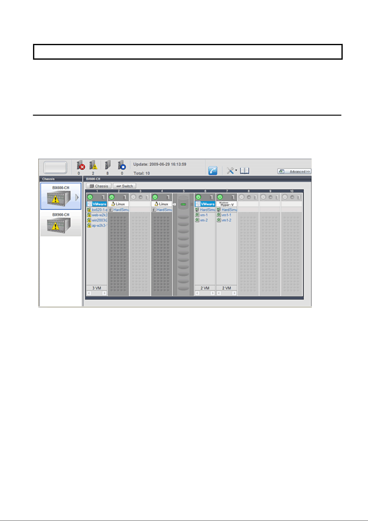
6.1 Overview
This section provides a functional overview of BladeViewer.
BladeViewer provides an intuitive representation of blade servers and their statuses. This makes it easier to monitor resource states or
perform basic operations on blade servers.
Figure 6.1 BladeViewer
BladeViewer allows the following operations:
- Monitoring of resource statuses
The statuses of chassis, servers, LAN switches, and physical OSs can be monitored from a view representative of the actual placement
and configuration of physical devices.
When using virtual servers, BladeViewer shows a list of VM guests for each VM host. This helps keeping track of relationships
between VM guests and VM hosts.
BladeViewer also makes it easy to confirm which operating systems (physical OS and guest OS) are affected by a hardware failure.
- Display and control of power status
The power status of each server blade, storage blade, and VM guest is represented by an intuitive power button.
Clicking this button provides quick access to power control operations (for both server blades and VM guests).
- Display of custom labels and comments
BladeViewer allows users to define custom labels and comments for each physical OS, VM host, and VM guest.
Once defined, labels are shown on top of each displayed physical OS, VM host, and VM guest. Using labels to display application
contents makes it easy to visualize what applications are running on each server blade and identify the applications affected by a server
failure.
Clicking on a label displays the comment defined for the related resource. Registering troubleshooting and recovery procedures
beforehand can speed up the recovery of affected applications when a problem occurs.
- 10 -
Page 26
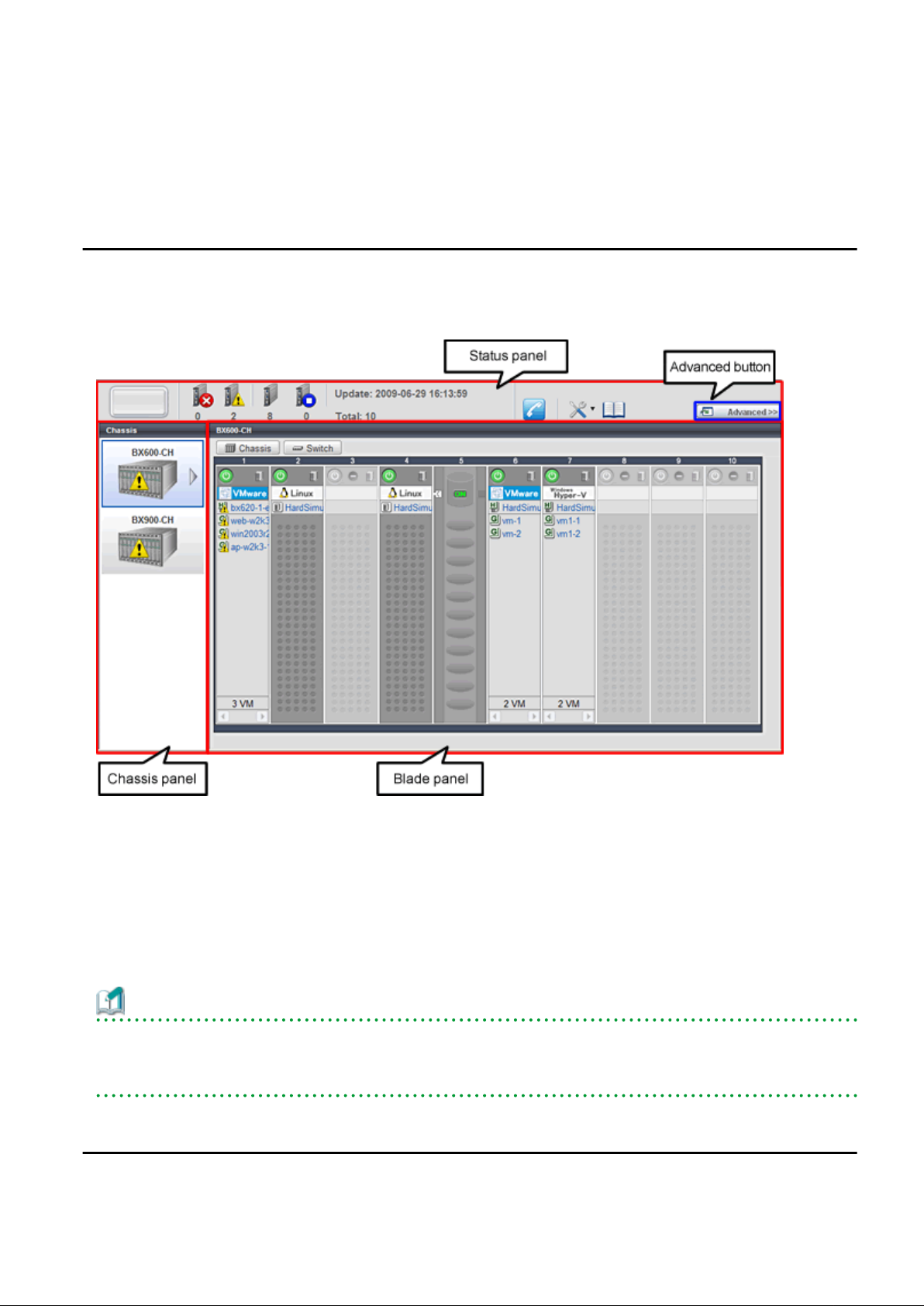
- Display of contact information
BladeViewer allows users to define technical (support) contact information for their entire IT system. This contact information can
be shown by clicking on the Contact icon.
Registering contact details of technical support staff beforehand can help streamline recovery procedures when problems occur.
6.2 Screen Layout
This section explains how the BladeViewer screen is organized.
The BladeViewer screen consists of a status panel, a chassis panel, and a blade panel.
Figure 6.2 BladeViewer: Screen Layout
Status panel
This panel displays a summary of resources statuses.
Chassis panel
This panel displays the statuses of each registered chassis.
Blade panel
This panel displays the status of all resources mounted within the selected chassis.
Information
To switch from BladeViewer to the ROR console, click <Advanced>>>, which is displayed in the upper-right of the BladeViewer screen.
Switch to the ROR console when necessary, for example to register servers and change various settings.
Otherwise, the last view used before logging out (either the ROR console or BladeViewer) is displayed.
6.3 Resource Status Monitoring
This section explains how to monitor resource statuses using BladeViewer.
- 11 -
Page 27
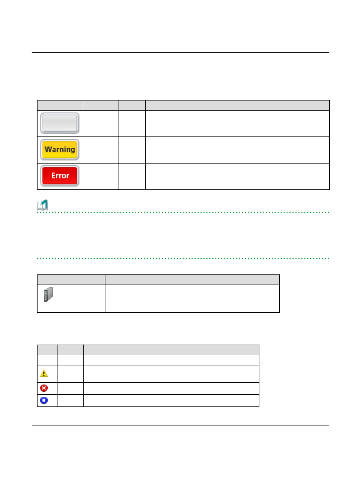
6.3.1 Status Panel
The status panel displays a summary of resources statuses (including resources other than PRIMERGY BX servers).
When a problem occurs in the system, a red or yellow light icon starts blinking on the left side of the status panel.
Clicking the light icon changes its color back to gray.
The table below shows the status and meaning associated with each light icon.
Table 6.1 Light Icons
Icon Color Status Meaning
Gray (not lit) Normal No errors or warnings have been detected in the system.
Yellow
(blinking)
Red
(blinking)
Warning A warning has been detected in the system.
Error An error has been detected in the system.
Information
When the light icon blinks, it means that a warning or an error has been detected. Check the location of the problem from the chassis or
blade panel.
If BladeViewer shows no resources with a warning or error status in either the chassis panel or blade panel, switch to the ROR console
and check the event log to identify the cause of the problem.
To the right of the light icon, BladeViewer shows the number of servers with an "error", "warning", "normal", and "stop" status.
Table 6.2 Displaying the Server Icon and the Number of Units
Icon and number of units Meaning
Server and number of units
N
(*)
* Note: N is the number of servers.
Table 6.3 Status Icons
Icon Status Meaning
None Normal The resource can be used normally.
Warning
Error A fault or error occurred, therefore the resource cannot be used.
Stop The resource is stopped, therefore it cannot be used.
An error occurred, however the resource can be used.
Alternatively, the status of some resources cannot be obtained.
6.3.2 Chassis Panel
The chassis panel displays the statuses of each registered chassis.
- 12 -
Page 28
Table 6.4 Chassis Icon
Icon Meaning
Chassis
See
For details on the different chassis statuses, refer to "Table 6.3 Status Icons" of "6.3.1 Status Panel".
If a chassis icon shows a warning or error status, it means that a problem occurred in a resource contained in the chassis.
For details on how to identify faulty resources, refer to "6.3.3 Blade Panel".
Information
Selecting a chassis icon from the chassis panel displays the contents of that chassis in the blade panel.
For details, refer to "6.3.3 Blade Panel".
6.3.3 Blade Panel
The blade panel displays the statuses of all the resources inserted into the selected chassis. Those resources are shown in a format
representative of their physical configuration (shape and position).
To display the contents of a specific chassis in the blade panel, click on its icon in the chassis panel.
In the blade panel, the selected chassis and its LAN switches are represented by the following icons. Those icons are displayed in the
upper-part of the blade panel.
Table 6.5 Chassis Icon
Icon Meaning
Chassis
Table 6.6 LAN Switch Icon
Icon Meaning
LAN switch
See
For details on the status icons that are displayed for the chassis and its LAN switches, refer to "Table 6.3 Status Icons" of "6.3.1 Status
Panel".
6.3.3.1 [Resource List] Tab
The blade panel graphically displays each slot within a chassis. Each server or storage blade is displayed according to its actual position
(slot) within the chassis.
Note that an unregistered server is shown in light gray while an empty slot is shown in white.
- 13 -
Page 29
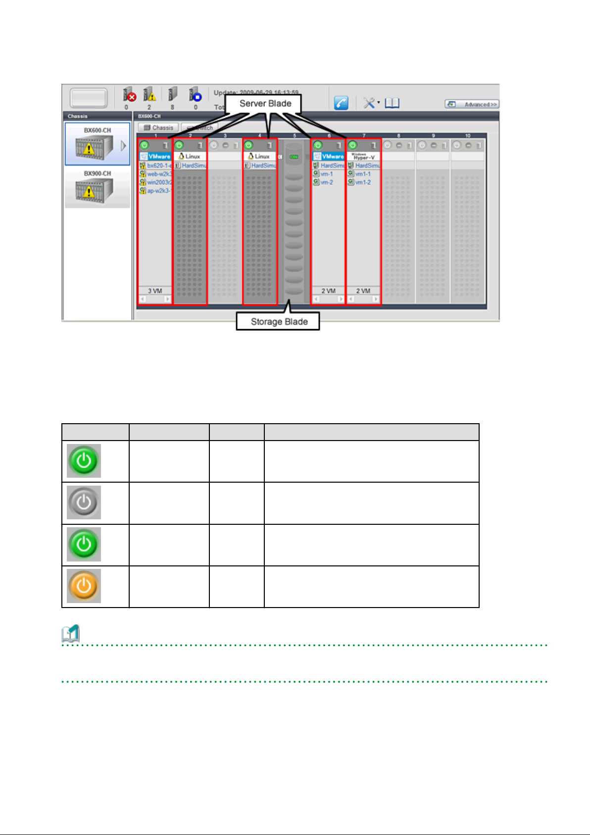
Figure 6.3 Blade Panel: Resource List
Server Blade
A power button is displayed in the upper-part of each server blade.
This power button is used to represent the power status of each server, as shown below.
Table 6.7 Server Blade Power Buttons
Power button Color Status Meaning
Green (lit) Power ON Power ON status.
Gray (not lit) Power OFF Power OFF status.
Green (blinking)
Orange (blinking)
Power ON
in progress
Power OFF
in progress
Power ON or reboot in progress.
Power OFF in progress.
Information
The power status of a server blade can be easily controlled by clicking on its power button.
For details, refer to "6.4.1 Server Blade".
A physical server icon is displayed on the right side of the server blade power button.
The table below shows the meanings associated with each physical server icon.
- 14 -
Page 30
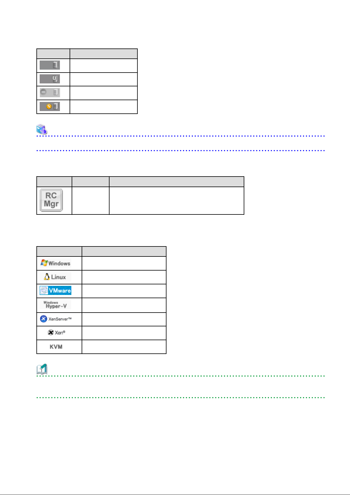
Table 6.8 Physical Server Icons
Icon Meaning
Server
Spare server
Unregistered server
Maintenance mode server
See
For details on the different physical server statuses, refer to "Table 6.3 Status Icons" in "6.3.1 Status Panel".
When a server blade is used as the admin server, the following admin server icon is displayed.
Table 6.9 Admin Server Icon
Icon Status Meaning
Admin server Indicates the server used as the admin server.
An OS icon is displayed below the physical server icon.
The table below shows the meaning of each OS icon.
Table 6.10 OS Icons
Icon Meaning
Windows OS
Linux OS
VMware host OS
Hyper-V host OS
Citrix XenServer host OS
Linux Xen host OS
KVM host OS
Information
Clicking on a VM host OS icon displays a detailed list of the VM guests operating on the selected VM host.
For details, refer to "6.3.3.2 VM Guest List".
A user-defined label is displayed with a resource icon below the OS icon.
- If no label is set
The OS name is displayed.
- 15 -
Page 31

- If the OS name cannot be acquired (because the OS has not been installed or for other reasons)
The server name (physical server name or VM guest name) is displayed.
The following table shows the resource icons used in BladeViewer and their associated meanings.
Table 6.11 Resource Icons
Icon Meaning
Physical OS
VM host
VM guest
See
For details on the resource status, refer to "Table 6.3 Status Icons" in "6.3.1 Status Panel".
Information
If a comment has been defined for a server, clicking on its label displays the [Server Properties] dialog.
The [Server Properties] dialog displays the comment and label set for the selected server, as well as its OS name, server name (for a
physical OS, the physical server name, for a VM guest, the VM guest name), and IP address.
For details on defining comments, refer to "6.5.1 Listing and Editing of Labels and Comments".
Storage Blade
A power lamp is displayed in the top part of each storage blade.
The table below shows the status and meaning associated with each power lamp.
Table 6.12 Storage Blade Power Lamps
Power lamp Color Status Meaning
Green (lit) Power ON Power ON status.
Gray (not lit) Power OFF Power OFF status.
6.3.3.2 VM Guest List
When a VM host is displayed in the blade panel, clicking the VM host OS icon displays a list of hosted VM guests with their statuses.
- 16 -
Page 32

Figure 6.4 Blade Panel: VM Guest List
A VM guest icon is shown on the left side of each VM guest displayed in the VM guest list.
Table 6.13 VM Guest Icon
Icon Meaning
VM guest
See
For details on the different VM guest statuses, refer to "Table 6.3 Status Icons" in "6.3.1 Status Panel".
A user-defined label is displayed on the upper-right side of the VM guest icon.
- If no label is set
The OS name is displayed.
- If the OS name cannot be acquired (because the OS has not been installed or for other reasons)
The VM guest name is displayed.
An OS icon is displayed below the label.
For details on the different OS icons, refer to "Table 6.10 OS Icons" in "6.3.3.1 [Resource List] Tab".
A power button is displayed on the lower-right side of each VM guest.
This power button represents the power status of each VM guest, as shown below.
Table 6.14 VM Guest Power Buttons
Power button Color Status Meaning
Green (lit) Power ON Power ON status.
Gray (not lit) Power OFF Power OFF status.
Green (blinking) Power ON in progress Power ON or reboot in progress.
- 17 -
Page 33

Power button Color Status Meaning
Orange (blinking)
Power OFF in
progress
Power OFF in progress.
Information
The power status of a VM guest can be easily controlled by clicking on its power button.
Refer to "6.4.2 VM Guest" for details.
6.3.4 Resource Details
To view a resource's details, click on its icon (chassis, LAN switch, or physical server icon) from the blade panel.
- Chassis
Clicking a chassis icon (from the blade panel) opens up its management blade's Web interface in a new window.
This Web interface provides more details on the chassis' status and contents.
For details on the chassis icon, refer to "6.3.3 Blade Panel".
- LAN switch
Clicking on a LAN switch icon opens up its LAN switch details screen.
This screen provides more details on the LAN switch's status and configuration.
For details on the LAN switch icon, refer to "6.3.3 Blade Panel".
- Physical server
Clicking on a physical server icon opens it up in the ServerView Operation Manager's Web interface.
This interface provides more details on the physical server's status and its internal components.
For details on the physical server icon, refer to "Table 6.8 Physical Server Icons" in "6.3.3.1 [Resource List] Tab".
6.4 Power Control
This section explains how to control the power status of server blades and VM guests from BladeViewer.
6.4.1 Server Blade
The power status of a server blade can be easily controlled by clicking its power button.
Table 6.15 Actions of Server Blade Power Buttons
Power button Color Status Action
Gray (not lit) Power OFF Powers on a server blade.
Green (lit) Power ON Shuts down or reboots a server blade.
Power On
Clicking on a power button that shows "Power OFF" status will power on the target server blade. A confirmation dialog is displayed first.
Clicking <OK> in the confirmation dialog powers on the server and starts its OS.
At this time, the power button changes to an intermediate "Power ON in progress" state (green - blinking). The power button finally
displays a "Power ON" state after confirming that the OS has started up correctly on the target server.
- 18 -
Page 34

Power Off and Reboot
Clicking on a power button that shows "Power ON" status will either shut down or reboot the target server blade. A [Power Operation]
dialog is displayed, in which the appropriate action can be selected.
Figure 6.5 Power Operation Dialog
- "Shutdown"
Selecting "Shutdown" will shut down the target server blade. A confirmation dialog is displayed first.
Clicking <OK> in the confirmation dialog shuts down the OS and powers off the managed server.
At this time, the power button changes to an intermediate "Power OFF in progress" state (orange - blinking). The power button finally
displays "Power OFF" status after confirming that the target server has been shut down correctly.
- "Reboot"
Selecting "Reboot" will reboot the target server blade. A confirmation dialog is displayed first.
Clicking <OK> in the confirmation dialog shuts down the OS and reboots the managed server.
At this time, the power button changes to an intermediate "Power ON in progress" state (green - blinking). The power button finally
displays "Power ON" status after confirming that the OS has started up correctly on the target server.
Forced Power Off and Reboot
Clicking on a power button that shows "Power ON" status, and selecting <Options >>> in the displayed [Power Operation] dialog enables
selection of the "Force Shutdown" and "Force Reboot" actions.
A forced shutdown (or reboot) will forcibly power off (or reboot) the managed server blade without waiting for its OS to shut down cleanly.
- 19 -
Page 35

Figure 6.6 Power Operation Dialog (with Additional Options)
- "Force Shutdown"
Selecting "Force Shutdown" will forcibly power off the target server blade. A confirmation dialog is displayed first.
Clicking <OK> in the confirmation dialog will power off the managed server without waiting for its OS to shut down cleanly.
At this time, the power button changes to an intermediate "Power OFF in progress" state (orange - blinking). The power button finally
displays "Power OFF" status after confirming that the target server has been shut down correctly.
- "Force Reboot"
Selecting "Force Reboot" will forcibly reboot the target server blade. A confirmation dialog is displayed first.
Clicking <OK> in the confirmation dialog will power off and reboot the managed server without waiting for its OS to shut down cleanly.
At this time, the power button changes to an intermediate "Power ON in progress" state (green - blinking). The power button finally
displays "Power ON" status after confirming that the OS has started up correctly on the target server.
Note
[VM Host]
Take caution regarding the following points when powering-off or rebooting a VM host.
- When using a server virtualization software's high-availability feature, confirm that the server is set to VM maintenance mode within
that virtualization software. This can be confirmed from the virtualization software client.
- Perform power operations only after setting VM maintenance mode (either from the VM management software client or using the
resource control command).
Refer to the server virtualization software manual, or to "3.2 rcxadm server" in the "Reference Guide (Command) VE" for details.
Depending on the server virtualization software used, some restrictions may apply to the use of VM maintenance mode settings. For
details about such restrictions, refer to "D.3 Functional Differences between Products" in the "Design Guide VE".
6.4.2 VM Guest
The power status of a VM guest can be controlled by clicking the OS icon of its VM host and then clicking its power button in the list of
VM guests that is displayed.
Clicking on the power button provides power controls similar to those provided for server blades.
Table 6.16 Actions of VM Guest Power Buttons
Power button Color Status Action
Gray (not lit) Power OFF Powers on a VM guest.
- 20 -
Page 36

Power button Color Status Action
Green (lit) Power ON Shuts down or reboots a VM guest.
Note
- VM guests need to be properly configured in order to use the shut down or reboot buttons.
Attempting to shut down or reboot a VM guest that is not properly configured will result in an error.
For details, refer to "D.2 Configuration Requirements" in the "Design Guide VE".
- Depending on the server virtualization environment, a VM guest may automatically migrate to another VM host when a power control
operation is performed. This may cause power control operations to fail and return an error when used on VM guests.
For details, refer to "D.3 Functional Differences between Products" in the "Design Guide VE".
- A VM guest can be configured to automatically start or stop whenever its VM host starts up or shuts down. This can be achieved by
configuring the VM guest's startup and shutdown options in the server virtualization software used.
For details, refer to the server virtualization software manual.
[Windows]
- Take caution regarding the following points when shutting down or rebooting a managed server running a Windows operating system.
- If Windows is not configured to shut down when the computer's power button is pressed, the power operations in Resource
Orchestrator may not function properly.
To check this option, access the Control Panel, open the [Power Options], and check the settings of the [Advanced] tab in the
[Power Options Properties] window.
- If a file is being edited by a logged-in user, a dialog prompting the user to save the file is displayed, and the system may not shut
down immediately.
In such cases, shutdown does not take place until the user takes the appropriate action or a specified time (approximately five
minutes) has elapsed.
6.5 Status Panel Operations
This section describes the operations that can be performed from the status panel.
Figure 6.7 BladeViewer: Tool Icons
- 21 -
Page 37

Contact icon
Displays the [Contact] dialog. This dialog shows the contact information that was set for the entire system.
Tools icon
Enables selection of the following menu options:
Display Label List
Displays the [Label List] dialog.
Displays a list of labels. This list also allows modification of labels and comments.
For details on editing labels and comments, refer to "6.5.1 Listing and Editing of Labels and Comments".
Set Contact Information
Displays the [Set Contact Information] dialog.
For details on modifying contact information, refer to "6.5.2 Editing Contacts".
Change Password
Displays the [Change Password] dialog.
For details on changing passwords, refer to "6.5.3 Changing Passwords".
Help icon
The Help is displayed.
6.5.1 Listing and Editing of Labels and Comments
Clicking on the Tools icon and selecting "Display Label List" from the drop-down list displays the [Label List] dialog shown below.
When applications are defined with labels, this list can provide a quick overview of the applications running on each server.
Figure 6.8 Label List
Contents of the Label List
The [Label List] dialog displays server names, OS names, labels, and comments for each server.
Clicking <Switch To> after selecting a server from the list will switch the view to the blade panel and display the selected server within
its enclosing chassis.
- 22 -
Page 38

Editing Labels and Comments
This function is only available to privileged users.
General users are only able to consult labels and comments.
- Privileged user
In the [Label List] dialog, select a server and click <Modify>. The [Modify Server Settings] dialog is displayed.
The label and comment of the selected server can be edited directly from the [Modify Server Settings] dialog.
Enter the following items:
Label
Enter up to 32 alphanumeric characters or symbols (ASCII characters 0x20 to 0x7e).
Comments
Enter up to 256 alphanumeric characters or symbols (ASCII characters 0x20 to 0x7e).
Note
New lines are counted as two characters.
Additional information such as OS name, server name (for a physical OS, the physical server name, for a VM guest, the VM guest
name), and IP address are displayed to help identify the selected server.
Clicking <Save> saves the modified label and comment into the manager's database. The saved content is then updated and displayed
in BladeViewer.
- General user
If logged in as a general user, <Show> is displayed in place of <Modify> in the [Label List] dialog.
Clicking <Show> displays the [Server Properties] dialog, but does not allow editing of labels or comments.
6.5.2 Editing Contacts
Clicking the Tools icon and selecting "Set Contact Information" from the drop-down list displays the [Set Contact Information] dialog.
This function is only available to privileged users. If logged in as a general user, the "Set Contact Information" menu item cannot be
selected.
Enter the following item.
Contact
The currently defined contact information is displayed.
Enter a maximum of 256 characters.
Note
New lines are counted as two characters.
Clicking <Save> saves the modified contact information into the manager's database. The saved content will be displayed the next time
the [Contact] dialog is opened.
6.5.3 Changing Passwords
Clicking the Tools icon and selecting "Change Password" from the drop-down list displays the [Change Password] dialog.
The required information varies according to the authority level of the logged in user, as described below. The password is changed after
entering the required information and clicking <Change>.
- 23 -
Page 39

- Privileged user
New password (Confirm password)
Enter a string using up to 16 alphanumeric characters or symbols.
- General user
Current password
Enter the password that is currently set.
Enter a string using up to 16 alphanumeric characters or symbols.
New password (Confirm password)
Enter a string using up to 16 alphanumeric characters or symbols.
- 24 -
Page 40

Chapter 7 Registering Resources
This chapter explains how to register, change, and delete resources used by Resource Orchestrator.
The Resource Orchestrator manager must be completely installed beforehand.
In addition to the usual method of registering each resource individually, it is also possible to register or change registered settings of
multiple resources in batches using the pre-configuration function.
- Registering or modifying resources individually
This method is used when the number of servers to be installed is small (from one to four), or when adding a similar number of servers
to an existing environment.
- Registering or modifying multiple resources collectively
This method is used when there are many (five or more) servers to be installed.
For information on how to register and modify multiple resources together, refer to "Chapter 12 Pre-configuration for Resource Registration
and Modification".
Information
- User Accounts
When creating new user accounts, changing passwords, or modifying permission levels during setup, refer to "Chapter 5 Managing
User Accounts".
- Backing up the Admin Server
The admin server should be backed up after the entire system has been completely set up, or after registering, changing, or deleting
resources.
For information about backing up the admin server, refer to "Chapter 9 Backup and Restoration of Admin Servers" in the "Operation
Guide VE".
7.1 Registering VIOM Coordination
Use the following procedure to configure management software settings:
1. From the ROR console menu, select [Settings]-[Register]-[Management Software (VIOM)].
The [Register Management Software(VIOM)] dialog is displayed.
2. To use this feature, the following settings must first be defined:
User ID
Enter the ID of a VIOM user account.
Password
Enter the password of the above VIOM user account.
3. Click <OK>.
7.1.1 Registering VIOM Server Profiles
Use the following procedure to configure VIOM server profiles:
1. Select Management Software (VIOM) from the ROR console, and then select the [Resource Details] tab.
2. In General of the [Resource Details] tab, click the link for the Management software.
The Web interface of ServerView Virtual-IO Manager starts up.
3. Refer to the ServerView Virtual-IO Manager manual to configure server profiles.
- 25 -
Page 41

Note
HBA address rename and VIOM cannot be used together within the same chassis.
When using backup and restore or cloning, prioritize the following two boot operations:
1. Boot from the first admin LAN network interface (NIC1 (Index1))
2. Boot from the network interface used by the admin LAN (NIC2 (Index2))
7.2 Registering VM Management Software
This section explains how to register VM management software.
Registration of VM management software (such as VMware vCenter Server) is necessary to enable VM guest migrations.
For details on the required VM management software settings, refer to "D.2 Configuration Requirements" in the "Design Guide VE".
Use the following procedure to register VM management software:
1. From the ROR console menu, select [Settings]-[Register], and then select the type of the VM management software to use.
The [Register Management Software(
name
, the type of the VM management software is displayed.
In
name
)] dialog is displayed.
2. To use this feature, the following settings must first be defined:
Management software name
Enter the name of the target VM management software.
Enter a character string beginning with an alphabetical character and containing up to 15 alphanumeric characters and hyphens
("-").
Location
Select the location where the VM management software to register is operating.
- If VM management software is installed on the admin server
Select [Admin Server].
- In other cases
Select [Other Server].
Selecting this option activates the IP address field. Enter the IP address of the server on which VM management software
is installed.
By default, [Admin Server] is selected.
IP address
Enter the IP address of VM management software. When specifying [Admin Server] for the location, entry is not possible, as
the IP address of admin server remains displayed.
Enter the IP address using periods ".".
Note
When receiving SNMP traps from VM management software (VMware vCenter Server), the configured IP address and the
SNMP trap source IP address of the VM management software (VMware vCenter Server) should be the same. The SNMP trap
source IP address is the IP address of the protocol with the highest priority of protocol binding. When changing the SNMP trap
source IP address, change the order of protocol binding.
User ID
Enter the user ID to use to control VM management software.
Enter up to 84 characters, including alphanumeric characters and symbols (ASCII characters 0x20 to 0x7e).
- 26 -
Page 42

Password
Enter the password for VM management software.
Enter up to 128 characters, including alphanumeric characters and symbols (ASCII characters 0x20 to 0x7e).
3. Click <OK>.
VM management software is registered with the entered information.
Information
Registration and management of multiple VM management software packages (VMware vCenter Server, etc) are possible.
It is also possible to register a single VM management product multiple times and use it for management.
The following VM management software can be registered in Resource Orchestrator.
- VMware vCenter Server
- System Center Virtual Machine Manager
7.3 When Using Blade Servers
This section explains how to register resources when using blade servers.
When using blade servers, use the following procedure to register resources:
- Register Chassis
- Register blade servers
- Register LAN switch blades
- Configure VLANs on LAN switch blades
7.3.1 Registering Chassis
This section explains how to register a chassis.
Registering chassis makes it possible to use the optional power monitoring settings.
When collecting power data, perform the power data collection settings according to "9.6.1 Changing Environmental Data Settings".
For details on devices supporting power monitoring, refer to "2.5 Hardware Environment" in the "Design Guide VE".
By registering a chassis, every server blade mounted in the chassis will be automatically detected and displayed as an unregistered server
in the server resource tree. Register these managed servers individually.
For details on registering servers to manage, refer to "7.3.2 Registering Blade Servers".
Use the following procedure to register a chassis:
1. In the ROR console server resource tree, right-click "Server Resources", and select [Register]-[Chassis] from the popup menu.
The [Register Chassis] dialog is displayed.
2. To use this feature, the following settings must first be defined:
Admin LAN (IP address)
Enter the IP address that was set on the chassis management blade.
Enter the IP address using periods ".".
Chassis name
Enter a name to assign to this chassis.
Enter a character string beginning with an alphabetical character and containing up to 10 alphanumeric characters and hyphens
("-").
- 27 -
Page 43

SNMP Community
Enter the SNMP community that was set on the chassis management blade.
Select either "public" or enter an arbitrary string.
Enter a string of up to 32 alphanumeric characters, underscores ("_"), and hyphens ("-").
3. Click <OK>.
The mounted chassis will be displayed under the server resource tree.
Any server blade mounted within this chassis will be detected automatically and shown as: [
Slot_number
The only operation available for those unregistered server blades is server registration, while the ROR console can only display
their hardware statuses and properties.
If the manager is installed on one of those server blades, this blade will be shown as: [
In that case, server registration will not be available for the admin server, but its hardware status and properties will be displayed
in the ROR console.
[Unregistered]].
chassis_name-Slot_number
chassis_name
[Admin Server]].
7.3.2 Registering Blade Servers
To register a blade server (PRIMERGY BX series), its enclosing chassis must be registered first.
When using VIOM for I/O virtualization, VIOM server profiles should be registered in advance according to the procedure described in
"7.1.1 Registering VIOM Server Profiles".
To register blade servers other than PRIMERGY BX servers, refer to "7.4 When Using Rack Mount and Tower Servers".
-
- 28 -
Page 44

Figure 7.1 Status Transition Diagram for Managed Servers
Use the following procedure to register blade servers.
1. In the ROR console server resource tree, right-click an unregistered server blade or partition in the target chassis, and select
[Register]-[Server] from the popup menu.
The [Register Server] dialog is displayed.
2. To use this feature, the following settings must first be defined:
Physical Server Name
Enter a name to assign to this physical server.
Enter a character string beginning with an alphabetical character and containing up to 15 alphanumeric characters and hyphens
("-").
Admin LAN (IP address)
Enter the IP address used by this server on the admin LAN.
When IP address is displayed
Entering an admin LAN (IP address) is not required.
Agents are automatically registered.
- 29 -
Page 45

Note
- If ServerView Agents (mandatory software) is not running, message number 67231 will be displayed. In this case, server
registration succeeds, but the agent is not registered.
For details on the appropriate corrective action, refer to "Message number 67231" in "Messages".
- If the admin LAN (IP address) of servers not running a physical OS or a VM host are displayed, old information may have
been being displayed. After cancelling registration of the server, right-click the chassis on the server resource tree and select
[Update] from the popup menu to request an update of hardware properties. The IP address is updated to the correct value
(it takes several seconds to obtain the information and to update).
When IP address is not displayed
Enter the IP address of this server's admin LAN network interface.
The Agent will not be registered automatically, but can be manually registered after server registration if necessary. After
registering servers, register agents as required.
Information
When a physical OS and VM host are running on this server, the admin LAN (IP address) may be obtained automatically.
After cancelling registration of the server, right-click the chassis on the server resource tree and select [Update] from the popup
menu to request an update of hardware properties.
If the IP address is not shown after going through the above procedure, set it by manually entering the IP address and registering
the server.
Server OS category
This option is displayed if the target server runs a physical OS or VM host.
Select the appropriate server OS category (Physical OS or VM host).
Selecting [VM Host] activates the user ID and password input fields. Those refer to the user name and password entered during
installation of this VM host.
Select the server OS category depending on whether the relevant server is used on a physical OS or a VM host.
- For a Physical OS
Select [Windows/Linux] or [Solaris].
- For a VM Host
Select [VM Host], and enter the VM host login account information.
This login account information will be used by Resource Orchestrator to control and communicate with the registered VM
host.
User ID
Enter the user ID to log in to the VM host. Specify a user ID that has VM host administrator authority.
Password
Enter the password of the user to log in to the VM host.
Boot option
Only set this when the targets of operations are PRIMEQUEST servers.
Specify the boot option configured from BIOS when installing the OS.
- For UEFI
Select [UEFI].
- For Legacy Boot
Select [Legacy boot].
By default, [UEFI] is selected.
- 30 -
Page 46

These settings can be changed after server registration.
For details on how to modify these settings, refer to "9.1.10 Changing Boot Options".
[Apply Admin LAN NIC settings] checkbox
The checkbox is displayed only for blade servers (PRIMERGY BX servers).
- When not changing the Admin LAN NIC settings
NIC1 (Index1) and NIC2 (Index2) are used, without changing the NICs used for the admin LAN, the HBA address rename
setup service, or for redundancy of the admin LAN.
- When changing the Admin LAN NIC settings
NIC1 (Index1) and NIC2 (Index2) are used as the NICs for the admin LAN, the HBA address rename setup service, and
redundancy of the admin LAN.
Select the NICs to use from Admin LAN (MAC address1) and Admin LAN (MAC address2).
Admin LAN (MAC address 1)
Displayed when the [Apply Admin LAN NIC settings] checkbox is selected.
Select the NIC to use for the admin LAN. The IP address allocated to the selected NIC is displayed in [Admin LAN (IP address)].
When an IP address is not allocated, specify the admin LAN (IP address) of the server to register.
Admin LAN (MAC address 2)
Displayed when the [Apply Admin LAN NIC settings] checkbox is selected.
Select the NICs used for the HBA address rename setup service or for admin LAN redundancy.
For the following cases, select the [Disable MAC address 2].
- When not using the HBA address rename setup service
- When not performing admin LAN redundancy
Note
- For details about the network interfaces used on the admin LAN, refer to "7.1 Network Configuration" in the "Design Guide VE".
If an incorrect network interface is used, Resource Orchestrator will use a wrong MAC address for the admin LAN.
An admin LAN IP address is required even when registering a spare server.
Enter an IP address that does not conflict with the IP address of any other managed server on the admin LAN.
- When using backup and restore, cloning, or HBA address rename, the NIC (or LAN expansion board) must support PXE boot.
- When registering a newly-mounted PRIMERGY BX900 server, as recognition of this server's admin LAN MAC address will
take time, error message number 61142 may be displayed.
In this case, after registration has been canceled, right-click the chassis on the server resource tree and select [Update] from the
popup menu to request an update of hardware properties. This will update the MAC address to the correct value. This may also
take a few minutes to obtain hardware information and update internal properties.
Confirm that the correct MAC address is displayed correctly before registering the server again.
For details on the appropriate corrective action, refer to "Message number 61142" in "Messages".
- A server running a VM host can still be registered as a physical OS if its [Server OS category] is set to [Windows/Linux]. (For
Windows Server 2008, etc.)
A VM host server that was mistakenly registered as a physical OS should be deleted and re-registered as a VM host.
- The same NIC cannot be selected for [Admin LAN (MAC address 1)] and [Admin LAN (MAC address 2)].
- For the following cases, after selecting [Disable MAC address 2] for [Admin LAN (MAC address 2)], the lowest numbered
NIC which is not used for [Admin LAN (MAC address 1)] is used for Admin LAN2.
- When using the HBA address rename setup service
- When performing admin LAN redundancy
- 31 -
Page 47

3. Click <OK>.
The registered server will be displayed in the server resource tree.
Note
- When an agent is registered on a VM host, all VM guests running on that VM host are also registered automatically. Whenever a VM
guest is created, modified, deleted, or moved on a registered VM host, the changes are automatically updated in the server resource
tree.
- The VM guest name displayed in the ROR console is either the VM name defined in its server virtualization software or the host name
defined in the guest OS.
The timing at which the host name of a guest OS is detected and displayed varies according its server virtualization software. For
details, refer to "D.3 Functional Differences between Products" in the "Design Guide VE".
- It is recommended not to use duplicate names for physical OSs, VM hosts, and VM guests. If duplicated names are used, those resources
cannot be managed from the command-line.
- When registering a server on which the agent was installed, it is necessary to either reboot the server or restart its related services
(explained in the "2.2 Starting and Stopping the Agent" in the "Operation Guide VE") after server registration. This step has to be
done before running any image operation (system image backup or cloning image collection).
For details on how to restart the agent, refer to "2.2 Starting and Stopping the Agent" in the "Operation Guide VE".
7.3.3 Registering LAN Switch Blades
To register a LAN switch blade, its enclosing chassis must be registered first.
Use the following procedure to register a LAN switch blade.
1. In the ROR console server resource tree, right-click an unregistered LAN switch blade from the target chassis, and select [Register]-
[LAN Switch] from the popup menu.
The [Register LAN Switch] dialog is displayed.
2. To use this feature, the following settings must first be defined:
LAN switch name
Enter the name to assign to this LAN switch blade.
Enter up to 15 characters, including alphanumeric characters (upper or lower case), underscores ("_"), and hyphens ("-").
Admin LAN (IP address)
Enter the admin LAN IP address that was set on this LAN switch blade.
Enter the IP address using periods ".".
User ID
Enter the name of a telnet or SSH user account that can log in to this LAN switch blade.
For a LAN switch blade PY CB DCB SW 10Gb 18/6/6, enter the name of the administrator account for the LAN switch blade.
Password
Enter the password of the above telnet or SSH user account.
Connection method
Select either [Telnet] or [SSH]. The default setting is as follows:
- LAN switch blade PY CB DCB SW 10Gb 18/6/6
[SSH]
- In other cases
[Telnet]
- 32 -
Page 48

Administrative password
Enter the password of this LAN switch blade's telnet or SSH administrator account.
If the user ID and the password of the administrator account for the LAN switch blade were set in [User ID] and [Password],
simply re-enter the same password in this field. In this case, Resource Orchestrator does not check whether the password entered
here matches the password set on the LAN switch blade.
SNMP Community
Enter the SNMP community that was set on this LAN switch blade.
Either select [public] or enter an arbitrary string.
Enter a string of up to 32 alphanumeric characters, underscores ("_"), and hyphens ("-").
3. Click <OK>.
The registered LAN switch blade will be displayed in the server resource tree.
Information
For a LAN switch blade PY CB DCB SW 10Gb 18/6/6, check that the following settings are displayed correctly in the resource details
of the LAN switch blade after it has been registered.
- Operation mode (VCS mode and other modes)
- VCS ID and RBridge ID
If a displayed value is incorrect, log in to the LAN switch blade and check that the settings of the VCS ID and RBridge ID are correct.
For the confirmation method, refer to the manual for the LAN switch.
If the settings of the VCS ID and RBridge ID are correct, delete the LAN switch blade and register it again.
Note
A telnet or SSH connection is made when registering a LAN switch blade.
When telnet or SSH (SSH version 2) connection is disabled, enable it.
Refer to the manual of the relevant product.
Some models may have restrictions regarding the number of simultaneous connections. In this case, log out from other connections.
If the connection is unavailable, the following features are also unavailable.
- Registration of LAN switch blades
- Changing of LAN switch blade settings
- Changing and setting the VLAN for LAN switch blades (internal and external connection ports)
- Restoration of LAN switch blades
- Server switchover (changing network settings while a server is switched over)
SSH connection (SSH version 2) can be selected for the following LAN switch blades.
- LAN switch blade PY CB Eth Switch/IBP 10Gb 18/8 (1.00 or later version)
- LAN switch blade PY CB Eth Switch/IBP 1Gb 36/8+2 (4.16 or later version)
- LAN switch blade PY CB Eth Switch/IBP 1Gb 36/12 (3.12 or later version)
- LAN switch blade PY CB Eth Switch/IBP 1Gb 18/6 (3.12 or later version)
- LAN switch blade PY CB DCB SW 10Gb 18/6/6 (2.1.1_fuj or later version)
7.3.4 Configuring VLANs on LAN Switches
On managed LAN switch blades, VLANs should be set on both internal ports (those connected to network interfaces on managed servers)
and external ports (those connected to external, adjacent LAN switches).
- 33 -
Page 49

Note
VLANs cannot be configured on PRIMERGY BX 900 and BX 400 LAN switch blades operating in IBP mode.
7.3.5 Configuring VLANs on External Ports
Use the following procedure to configure VLANs on a LAN switch blade's external ports.
1. In the ROR console server resource tree, right-click the target LAN switch blade and select [Modify]-[Network Settings] from the
popup menu.
The [VLAN Settings] dialog is displayed.
2. To use this feature, the following settings must first be defined:
VLAN
Specify the VLAN ID to assign to a LAN switch blade port.
Adding a new VLAN ID
a. Under VLAN, select [Create new].
b. Enter a VLAN ID number.
For details on VLAN IDs, refer to the manual of the LAN switch blade to be used.
Modifying an existing VLAN ID
a. Under VLAN, select [Change].
b. Select a VLAN ID.
Physical Port, Link Aggregation
Select port numbers to configure or VLAN types of link aggregation group names ([Untagged] or [Tagged]).
3. Click <OK>.
Check that the VLAN has been set.
4. Select the LAN switch blade in the server resource tree of the ROR console and display the [Resource Details] tab.
Confirm that the VLAN information is displayed in [VLAN Area] on [Resource Details].
Note
For a LAN switch blade PY CB DCB SW 10Gb 18/6/6, the VLAN settings of external ports cannot be configured.
7.3.6 Configuring VLANs on Internal Ports
Use the following procedure to configure VLANs on a LAN switch blade's internal ports.
1. In the ROR console server resource tree, right-click the target server (or the physical OS or VM host on the server), and select
[Modify]-[Network Settings] from the popup menu.
The [Network Settings] dialog is displayed.
2. Select the index of the network interface for which to assign a VLAN ID, and click <Setting>.
The [VLAN Configuration] dialog is displayed.
3. To use this feature, the following settings must first be defined:
Port VLAN
VLAN ID
Enter the VLAN ID to assign to the LAN switch blade port that is connected to the network interface selected in step 2.
- 34 -
Page 50

Tagged VLAN
VLAN ID
Enter the tagged VLAN ID(s) to assign to the LAN switch blade port that is connected to the network interface selected in
step 2.
Multiple VLAN IDs can be entered by separating them with commas (",").
4. Click <OK>
Note that the VLAN settings are not applied onto the LAN switch blade at this stage. To configure VLANs for multiple network
interfaces, repeat steps 2 to 4.
5. Confirm the configuration set in the [Network Settings] dialog.
6. Click <OK>.
VLAN settings are applied to the related LAN switch blade.
Note
When the VLAN configuration of a registered LAN switch blade is changed from the Web-based or command-based interface of the LAN
switch, it may take a while for that configuration to be reflected on Resource Orchestrator through periodic queries.
When performing server switchover before new VLAN information is reflected, the VLAN information previously set is configured in
LAN switch blades. Set the VLAN configuration from the ROR console instead of the LAN switch's own Web-based and command-based
interfaces.
If the Port VLAN ID field is left blank and a value is entered for Tagged VLAN ID in the [VLAN Configuration] dialog, the tagged LAN
only will be enabled. To enable a port VLAN, enter a value for Port VLAN ID.
When only a tagged VLAN is configured, the value for the port VLAN is not displayed on the ROR console even if it has been configured
on the switch. For the devices for which port VLANs cannot be deleted, it is necessary to limit the frames that let ports pass through to
the tagged frames only.
If the port VLAN ID is unspecified or 1, a tagged VLAN ID cannot be set to 1.
VLAN settings cannot be configured for ports with Automatic Migration of Port Profile (AMPP) configured.
7.3.7 HBA address rename Settings
For details, refer to "7.4.3 HBA address rename Settings".
7.4 When Using Rack Mount and Tower Servers
This section explains how to register resources when using rack mount or tower servers.
When using rack mount or tower servers, use the following procedure to register resources:
- Register Rack Mount or Tower Servers
- Register LAN Switches
7.4.1 Registering Rack Mount or Tower Servers
This section explains how to register a rack mount or tower server.
When using VIOM for I/O virtualization, VIOM server profiles should be registered in advance according to the procedure described in
"7.1.1 Registering VIOM Server Profiles".
- 35 -
Page 51

Figure 7.2 Status Transition Diagram for Managed Servers
Use the following procedure to register rack mount or tower servers.
1. In the ROR console server resource tree, right-click [Server Resources], and select [Register]-[Server] from the popup menu.
The [Register Server] dialog is displayed.
2. To use this feature, the following settings must first be defined:
Enter items differ depending on whether the [Register agent] checkbox is selected, as described below.
If this checkbox is checked, agents will be registered after server registration.
If this checkbox is not checked, registration of agents will not be performed, so register agents after server registration when
necessary.
Without Agent Registration
- Physical server name
- Remote management controller
- IP address
- User ID
- Password
- Association with server management software (ServerView)
- Enable/Disable
- SNMP Community
- 36 -
Page 52

- Admin LAN
- IP address
- MAC address (NIC1)
- SAN Boot/Admin LAN Redundancy
- MAC address (NIC2)
Automatic registration of agents is not performed after server registration. After registering servers, register agents as required.
If registering agents, register agents after checking the product name is displayed in the General Area of [Resource Details] tab.
Executing [Update] acquires the latest information.
With Agent Registration
- Physical server name
- Remote management controller
- IP address
- User ID
- Password
- Association with server management software (ServerView)
- Enable/Disable
- SNMP Community
- Admin LAN
- IP address
- Admin LAN Redundancy
- MAC address (NIC2)
- OS
- Type
Agents are automatically registered after server registration is completed.
Physical Server Name
Enter a name to assign to this physical server.
Enter a character string beginning with an alphabetical character and containing up to 15 alphanumeric characters and hyphens
("-").
Remote management controller
IP address
Enter the IP address of this server's remote management controller.
User ID
Enter the ID of a remote management controller user account with administrative authority over this server.
Enter up to 16 characters, including alphanumeric characters and symbols (ASCII characters 0x20 to 0x7e).
Password
Enter the password of the above remote management controller user account.
Enter up to 16 characters, including alphanumeric characters and symbols (ASCII characters 0x20 to 0x7e).
This field can be omitted if no password has been set for this user account.
- 37 -
Page 53

Association with server management software (ServerView)
Enable/Disable
For PRIMERGY BX servers
Select [Enable] and enter an [SNMP Community].
For servers other than PRIMERGY servers
Select [Disable].
By default, [Enable] is selected.
SNMP Community
Enter the SNMP community that was set on this server.
Select either "public" or enter an arbitrary string.
Enter a string of up to 32 alphanumeric characters, underscores ("_"), and hyphens ("-").
Admin LAN
IP address
Enter the IP address used by this server on the admin LAN.
MAC address (NIC1)
Enter the MAC address of this server's admin LAN network interface.
Enter a physical MAC address in either one of the following formats: hyphen-delimited ("xx-xx-xx-xx-xx-xx"), or colondelimited ("xx:xx:xx:xx:xx:xx").
MAC addresses will be automatically detected when the [Register agent] checkbox is selected.
SAN Boot/Admin LAN Redundancy
MAC address (NIC2)
Enter the MAC address of the second admin LAN network interface. This network interface is to be used by the HBA address
rename setup service, or to enable admin LAN redundancy on the registered server.
Enter a physical MAC address in either one of the following formats: hyphen-delimited ("xx-xx-xx-xx-xx-xx"), or colondelimited ("xx:xx:xx:xx:xx:xx").
This field can be omitted in the following cases.
- When not using the HBA address rename setup service
- When not using GLS for admin LAN redundancy on the managed server
- For a spare server whose primary servers are not using admin LAN redundancy
Admin LAN Redundancy
MAC address (NIC2)
Enter the MAC address of the second admin LAN network interface. This network interface will be used to enable admin
LAN redundancy on the registered server.
Enter a physical MAC address in either one of the following formats: hyphen-delimited ("xx-xx-xx-xx-xx-xx"), or colondelimited ("xx:xx:xx:xx:xx:xx").
This field can be omitted in the following cases.
- When not using GLS for admin LAN redundancy on the managed server
- For a spare server whose primary servers are not using admin LAN redundancy
OS
Type
This option is displayed if the target server runs a physical OS or VM host.
Select the appropriate server OS category (Physical OS or VM host).
Selecting [VM Host] activates the user ID and password input fields. Those refer to the user name and password entered
during installation of this VM host.
Select the server OS category depending on whether the relevant server is used on a physical OS or a VM host.
- 38 -
Page 54

For a Physical OS
Select [Windows/Linux].
For a VM Host
Select [VM Host], and enter the VM host login account information.
This login account information will be used by Resource Orchestrator to control and communicate with the registered VM
host.
User ID
Enter the user ID to log in to the VM host. Specify a user ID that has VM host administrator authority.
Password
Enter the password of the user to log in to the VM host.
Note
- For details about the network interfaces used on the admin LAN, refer to "7.1 Network Configuration" in the "Design Guide VE".
If an incorrect network interface is used, Resource Orchestrator will use a wrong MAC address for the admin LAN.
An admin LAN IP address is required even when registering a spare server.
Enter an IP address that does not conflict with the IP address of any other managed server on the admin LAN.
- When using backup and restore, cloning, or HBA address rename, the NIC (or LAN expansion board) must support PXE boot.
- A server running a VM host can still be registered as a physical OS if its [Category] of [Server OS] is set to [Windows/Linux].
(For Windows Server 2008, etc.)
A VM host server that was mistakenly registered as a physical OS should be deleted and re-registered as a VM host.
- When registering rack mount servers on which VMware ESXi is operating, select [Disable] for [Association with server
management software (ServerView)] even when using PRIMERGY servers.
After registering the server, clear the [Register agent] checkbox and register the agent after registration of the server is complete.
3. Click <OK>.
The registered server will be displayed in the server resource tree.
Note
- After registering the server, please verify that the information registered for the remote management controller is correct. This can be
verified by trying out power operations (from Resource Orchestrator) against that server. Refer to "Chapter 14 Power Control" for
power operations.
- When using HBA address rename setup service, please confirm that the registered server can boot properly using the HBA address
rename setup service.
If the server cannot be booted properly, ensure that the specified MAC address (NIC2) is correct.
- When an agent is registered on a VM host, all VM guests running on that VM host are also registered automatically. Whenever a VM
guest is created, modified, deleted, or moved on a registered VM host, the changes are automatically updated in the server resource
tree.
- The VM guest name displayed in the ROR console is either the VM name defined in its server virtualization software or the host name
defined in the guest OS.
The timing at which the hostname of a guest OS is detected and displayed varies according its server virtualization software. For
details, refer to "D.3 Functional Differences between Products" in the "Design Guide VE".
- It is recommended not to use duplicate names for physical OSs, VM hosts, and VM guests. If duplicated names are used, those resources
cannot be managed from the command-line.
- When registering a server on which the agent was installed, it is necessary to either reboot the server or restart its related services
(explained in the "2.2 Starting and Stopping the Agent" in the "Operation Guide VE") after server registration. This step has to be
done before running any image operation (system image backup or cloning image collection).
For details on how to restart the agent, refer to "2.2 Starting and Stopping the Agent" in the "Operation Guide VE".
- 39 -
Page 55

7.4.2 Registering LAN Switches
Use the following procedure to register LAN switches:
1. Discover LAN switches. For instructions, refer to "Discovery".
2. Register LAN switches displayed in the network device tree. For instructions, refer to "Registration".
Discovery
1. From the ROR console menu, select [Tools]-[Topology]-[Discover LAN switches].
The [Discover LAN Switches] dialog is displayed.
2. To use this feature, the following settings must first be defined:
Start address
Enter the start IP address of the network where to discover LAN switches.
Enter the IP address using periods ".".
Subnet mask
Enter the subnet mask of the network where to discover LAN switches.
Enter the IP address using periods ".".
Addresses in range
Enter the number of addresses to scan for LAN switches.
Enter a number greater than 1.
The maximum number of addresses is determined by the number of hosts allowed by the subnet mask.
Example
If subnet mask is "255.255.255.0", the number of addresses in the specified range could be any value between 1 and 256.
SNMP Community
Enter the SNMP community that was set on this LAN switch.
Either select [public] or enter an arbitrary string.
Enter a string of up to 32 alphanumeric characters, underscores ("_"), and hyphens ("-").
3. Click <OK>.
Resource Orchestrator starts scanning for LAN switches within the specified network range.
Discovered LAN switches will be displayed under the network device tree with the status [[Unregistered]].
Registration
1. In the ROR console network device tree, right-click a discovered LAN switch, and select [Register]-[LAN Switch] from the popup
menu.
The [Register LAN Switch] dialog is displayed.
2. To use this feature, the following settings must first be defined:
LAN switch name
Enter the name to assign to this LAN switch blade.
Enter up to 32 characters, including alphanumeric characters (upper or lower case), underscores ("_"), hyphens ("-"), or periods
(".").
By default, the name of a discovered LAN switch will be set to its system name or to its IP address if the system name could
not be detected.
- 40 -
Page 56

SNMP Community
Enter the SNMP community that was set on this LAN switch.
Either select [public] or enter an arbitrary string.
Enter a string of up to 32 alphanumeric characters, underscores ("_"), and hyphens ("-").
3. Click <OK>.
The registered LAN switch will be displayed in the network device tree.
Note
It is possible to set an automatically detected IP address to another unregistered LAN switch. However, this will result in the Resource
Orchestrator configuration being inconsistent with the actual network configuration.
If a LAN switch was registered with the IP address of another network device, delete the registered LAN switch following the instructions
given in "11.4.2 Deleting LAN Switches ", then perform Discover and Register again.
7.4.3 HBA address rename Settings
Use the following procedure to configure HBA address rename settings.
The HBA address rename function allows the admin server to control the WWNs set on a managed server's HBAs. Since the admin server
carried over these settings when performing maintenance on or switching managed servers, it is not necessary to set the storage side
configuration again.
Use of the HBA address rename function requires registering specific settings for each managed server in advance.
Note
- The HBA address rename function is not available if ServerView Deployment Manager is used on the admin LAN. For details, refer
to "Appendix B Co-Existence with ServerView Deployment Manager" in the "Setup Guide VE".
- For servers which already have server switchover configured, when configuring or changing HBA address rename, the following
conditions must be met:
- Primary servers with HBA address rename configured
- Spare servers with the server switchover method HBA address rename configured
For any servers that do not meet these conditions, cancel any existing recovery settings before enabling the HBA address rename
function on a server.
- HBA address rename and VIOM cannot be used together within the same chassis.
- When using PRIMEQUEST, FC cards set with HBA address rename cannot use the PHP function.
Restarting of a server is required after replacing the FC card.
1. Storage Settings
Refer to "8.2Configuring the Storage Environment" in the "Design Guide VE"to configure the storage.
When altering the configuration of a storage device already used by active servers, ensure those servers are powered off before performing
any configuration changes.
2. Settings for the HBA address rename Function
1. On the ROR console server resource tree, right-click the target server (or the physical OS or VM host on the server), and select
[Modify]-[HBA Address Rename Settings] from the popup menu.
The [HBA Address Rename Settings] dialog is displayed.
- 41 -
Page 57

2. Define the following settings:
WWNN
Specify the WWNN value provided by the "I/O virtualization Option".
The admin server generates WWPNs automatically from the values that are input into the WWNN and the number of HBA
ports.
HBA ports
Specify the following values according to the system configuration.
- To create a single-path configuration, specify "1".
For details, refer to "Figure 7.3 Procedures for Single-path Configurations".
- To create a multi-path configuration, specify "2".
However, it is necessary to specify "1" during installation of the operating system. Specify "2" and reconfigure HBA address
rename settings after setting up the multi-path driver.
For details, refer to "Figure 7.4 Procedures for Multi-path Configurations".
Figure 7.3 Procedures for Single-path Configurations
- 42 -
Page 58

Figure 7.4 Procedures for Multi-path Configurations
Example
For a server with two ports, WWNs could be configured as follows.
WWNN value provided by "I/O Virtualization Option": 20:00:00:17:42:51:00:00
Values to set in the [HBA address rename settings] dialog
"WWNN" value 20:00:00:17:42:51:00:00
"HBA port number" on board: 2
Values actually set by the admin server on the HBA (WWPNs are generated automatically)
WWNN value for ports 1 and 2 of the HBA : 20:00:00:17:42:51:00:00
WWPN value for HBA port 1 : 21:00:00:17:42:51:00:00
WWPN value for HBA port 2 : 22:00:00:17:42:51:00:00
Information
WWN settings are applied to managed servers during server startup.
3. Check the [Restart the server] checkbox if the server is to be restarted.
Information
Select server restart in the following cases.
- When installing an operating system immediately after performing the above settings
Insert the operating system installation CD in the target server and select server restart. Once the server has been restarted, its
WWN settings are applied and the operating system installation starts.
- When an operating system is already running (if changing storage settings)
Click <OK> to restart the target server and apply its WWN settings.
- 43 -
Page 59

The server restart is not required in other cases. The WWN that has been set is enabled at the next restart.
4. Click <OK>.
Information
When using a server without an OS, the resource name displayed on the server resource tree is the same as that of the physical
server.
5. Restart the HBA address rename setup service.
The HBA address rename setup service must be running to use the HBA address rename function.
For details on how to configure these settings, refer to "Chapter 6 Settings for the HBA address rename Setup Service" in the "Setup
Guide VE".
7.5 When Using PRIMEQUEST Servers
This section explains how to register resources when using PRIMEQUEST servers.
- Registering Chassis (For PRIMEQUEST Servers)
- Registering PRIMEQUEST Servers
7.5.1 Registering Chassis (For PRIMEQUEST Servers)
By registering a chassis, every partition mounted in the chassis will be automatically detected and displayed as an unregistered server in
the server resource tree. Register these managed servers individually.
For details on registering servers, refer to "7.5.2 Registering PRIMEQUEST Servers".
Use the following procedure to register a chassis:
1. In the ROR console server resource tree, right-click [Server Resources], and select [Register]-[PRIMEQUEST] from the popup
menu.
The [Register Chassis] dialog is displayed.
2. To use this feature, the following settings must first be defined:
Admin LAN (IP address)
Enter the virtual IP address that was set on the chassis management board.
Enter the IP address using periods ".".
Chassis name
Enter a name to assign to this chassis.
Enter a character string beginning with an alphabetical character and containing up to 10 alphanumeric characters and hyphens
("-").
SNMP Community
Enter the SNMP community that was set on the chassis management board.
Either select [public] or enter an arbitrary string.
Enter a string of up to 32 alphanumeric characters, underscores ("_"), and hyphens ("-").
Remote server management
User ID
Enter the ID of a remote server management user account with administrative authority over this managed server.
This user ID must be between 8 and 16 alphanumeric characters long.
A user ID with at least administrator privileges within the remote server management must be specified.
- 44 -
Page 60

Password
Enter the password of the above remote server management user account.
This password must be between 8 and 16 alphanumeric characters long.
Note
The [User ID] and [Password] of [Remote server management] are different from the user name and password used to log in on
the Web-UI for management board.
3. Click <OK>.
The mounted chassis will be displayed under the server resource tree.
Any partition mounted within this chassis will be detected automatically and shown as: [
partition_number
The only operation available for those unregistered partitions is server registration, while the ROR console can only display their
hardware statuses and properties.
If the manager is installed on one of those partitions, this partition will be shown as: [
Server]].
In that case, server registration will not be available for the admin server, but its hardware status and properties will be displayed
in the ROR console.
[Unregistered]].
7.5.2 Registering PRIMEQUEST Servers
For details on PRIMEQUEST server registration, refer to "7.3.2 Registering Blade Servers".
chassis_name
chassis_name-partition_number
-
[Admin
7.6 When Using SPARC Servers/SPARC Enterprise
This section explains how to register resources when using SPARC Servers/SPARC Enterprise.
- Registering chassis (SPARC Enterprise M4000/M5000/M8000/M9000 or SPARC M10-4S
- Registering SPARC Enterprise (M3000/T Series) servers or SPARC M10-1/M10-4
7.6.1 Registering Chassis (SPARC Enterprise M4000/M5000/M8000/M9000) or SPARC M10-4S
By registering a chassis, every partition mounted in the chassis will be automatically detected and displayed as an unregistered server in
the server resource tree. Register these managed servers individually.
For details on registering managed servers, refer to "7.6.2 Registering SPARC Enterprise (M3000/T Series) and SPARC M10-1/M10-4".
Use the following procedure to register a chassis:
1. In the ROR console server resource tree, right-click [Server Resources], and select as below.
- For SPARC Enterprise M4000/M5000/M8000/M9000 servers
Select [Register]-[SPARC Enterprise (Partition Model)] from the popup menu.
- For SPARC M10-4S
Select [Register]-[SPARC M10-4S] from the popup menu.
The [Register Chassis] dialog is displayed.
2. To use this feature, the following settings must first be defined:
Admin LAN (IP address)
Enter the IP address of the XSCF of the target chassis.
Enter the IP address using periods ".".
- 45 -
Page 61

Chassis name
Enter a name to assign to this chassis.
Enter a character string beginning with an alphabetical character and containing up to 10 alphanumeric characters and hyphens
("-").
SNMP Community
Enter the SNMP community of the XSCF used to manage the target chassis.
Either select [public] or enter an arbitrary string.
Enter a string of up to 32 alphanumeric characters, underscores ("_"), and hyphens ("-").
Remote management controller (XSCF)
User ID
Enter the ID of an XSCF user account with administrative authority over the target chassis.
Enter a string of up to 31 alphanumeric characters, hyphens ("-"), and underscores ("_"). This name must start with an alphabet
character.
This user should have "platadm" privileges for XSCF.
The user ID reserved for the system cannot be used. Create another user ID.
For details, refer to the XSCF manuals.
Password
Enter the password of an XSCF user account with administrative authority over the target chassis.
Enter up to 32 characters, including alphanumeric characters, blank spaces (" "), and any of the following symbols.
"!", "@", "#", "$", "%", "^", "&", "*", "[", "]", "{", "}", "(", ")", "-", "+", "=", "~", ",", ">", "<", "/", "'", "?", ";", ":"
3. Click <OK>.
The mounted chassis will be displayed under the server resource tree.
Any partition mounted within this chassis will be detected automatically and shown as: [
partition_number
The only operation available for those unregistered partitions is server registration, while the ROR console can only display their
hardware statuses and properties.
[Unregistered]].
chassis_name
7.6.2 Registering SPARC Enterprise (M3000/T Series) and SPARC M10-1/ M10-4
This section explains the methods for registering SPARC Enterprise (M3000/T series) and SPARC M10-1/M10-4.
This section also describes how to register servers in SPARC Enterprise M4000/M5000/M8000/M9000 and SPARC M10-4S chassis.
[Solaris Zones] [OVM for SPARC]
When the Logical Domains Manager daemon is enabled, VM hosts can be registered as Solaris Zones by configuring the definition files.
For details, refer to "D.4 Definition Files of Each Product" in the "Design Guide VE".
Use the following procedure to register servers:
1. The dialog is displayed.
- For SPARC Enterprise (M3000/T series)
In the ROR console server resource tree, right-click [Server Resources], and select as below.
Select [Register]-[SPARC Enterprise (M3000/T Series)] from the popup menu.
-
The [Register SPARC Enterprise] dialog is displayed.
- For SPARC M10-1/M10-4
In the ROR console server resource tree, right-click [Server Resources], and select as below.
Select [Register]-[SPARC M10-1/M10-4] from the popup menu.
The [Register SPARCM10-1/M10-4] dialog is displayed.
- 46 -
Page 62

- For SPARC Enterprise M4000/M5000/M8000/M9000 or SPARC M10-4S
Right-click the server in the chassis, and select as follows:
Select [Register]-[Server] from the popup menu.
The [Register Server] dialog is displayed.
2. To use this feature, the following settings must first be defined:
When using SPARC Enterprise M4000/M5000/M8000/M9000 or SPARC M10-4S, the items related to Remote Management
Controller are not displayed.
- Physical Server Name
- [Register agent] checkbox
- Remote management controller (ILOM/XSCF)
- Controller type
- IP address
- User ID
- Password
- SNMP Community
- Admin LAN
- IP address
With Agent Registration
- OS
- Type
- User ID
- Password
Physical Server Name
Enter a name to assign to this physical server.
Enter a character string beginning with an alphabetical character and containing up to 15 alphanumeric characters and hyphens
("-").
[Register agent] checkbox
- Without Agent Registration
Automatic registration of agents is not performed after server registration.
After registering servers, register agents as required.
If registering agents, register agents after checking the product name is displayed in the General Area of [Resource Details]
tab.
Executing [Update] acquires the latest information.
- With Agent Registration
Agents are automatically registered after server registration is completed.
Remote management controller (ILOM/XSCF)
For SPARC Enterprise M3000 or SPARC M10-1/M10-4
Controller type
Select [XSCF].
- 47 -
Page 63

IP address
Enter the IP address of this server's remote management controller (XSCF).
User ID
Enter the ID of a XSCF user account with administrative authority over this server.
Enter up to 31 characters, including alphanumeric characters, underscores ("_"), or hyphens ("-"). This name should start
with an alphabet character.
This user should have "platadm" privileges for XSCF.
The user ID reserved for the system cannot be used. Create another user ID.
For details, refer to the XSCF manuals.
Password
Enter the password of the above XSCF user account.
Enter up to 32 characters, including alphanumeric characters, blank spaces (" "), and any of the following symbols.
"!", "@", "#", "$", "%", "^", "&", "*", "[", "]", "{", "}", "(", ")", "-", "+", "=", "~", ",", ">", "<", "/", "'", "?", ";", ":"
SNMP Community
Enter the SNMP community that was set on this server's remote management controller (XSCF).
Either select [public] or enter an arbitrary string.
Enter a string of up to 32 alphanumeric characters, underscores ("_"), and hyphens ("-").
For SPARC Enterprise T series
Controller type
Select [ILOM].
IP address
Enter the IP address of this server's remote management controller (ILOM).
User ID
Enter the ID of an ILOM user account with administrative authority over this server.
Enter between 4 and 16 characters, including alphanumeric characters, underscores ("_"), or hyphens ("-"). This name should
start with an alphabet character.
This user ID should have "Admin" privileges for ILOM.
Password
Enter the password of the above ILOM user account.
Enter between 8 and 16 characters, including alphanumeric characters, blank spaces (" "), and any of the following symbols.
"!", "@", "#", "$", "%", "^", "&", "*", "[", "]", "{", "}", "(", ")", "-", "+", "=", "~", ",", ">", "<", "/", "'", "?", ";", ":"
SNMP Community
Enter the SNMP community name of this server's remote management controller (ILOM).
Either select [public] or enter an arbitrary string.
Enter a string of up to 32 alphanumeric characters, underscores ("_"), and hyphens ("-").
Admin LAN
IP address
Enter the IP address used by this server on the admin LAN.
Server OS
Category
Select the appropriate server OS category (Physical OS or VM host).
Selecting [Solaris Zone] activates the user name and password input fields.
Those refer to the user name and password entered during installation of this VM host.
For a Physical OS
Select [Solaris].
- 48 -
Page 64

For a VM Host
Select [VM Host], and enter the VM host login account information.
This login account information will be used by Resource Orchestrator to control and communicate with the registered VM
host.
User ID
Enter the user ID to log in to the VM host.
Specify the user ID "root" which has VM host administrator authority.
Note
When using Solaris 11, if user accounts are created during installation, root will be registered for the role. Therefore, the
root account cannot be used for login. Log in using the user account, and use the su command to become a root user.
When using Solaris 10 or earlier versions, execute the following as root in order to change to enable direct login using the
root account. In this case, the root role is recognized as a root user.
rolemod -K type=normal root <RETURN>
Use SSH connection with the root account, and check if communication with the VM host is possible.
If communication fails, modify the configuration. For details, refer to the manual of the basic software.
Password
Enter the password of the user to log in to the VM host.
Enter up to 256 characters, including alphanumeric characters, blank spaces (" "), and symbols.
3. Click <OK>.
The registered server will be displayed in the server resource tree.
Note
After registering the server, please verify that the information registered for the remote management controller is correct. This can be
verified by trying out power operations (from Resource Orchestrator) against that server. Refer to "Chapter 14 Power Control" for power
operations.
7.7 Registering Power Monitoring Devices
This section explains how to register power monitoring devices.
Registering power monitoring devices (PDU or UPS) enables monitoring of power consumption.
Use the following procedure to register power monitoring devices.
1. In the ROR console power monitoring device tree, right-click [Power Monitoring Devices] and select [Register]-[Power Monitoring
Device] from the popup menu.
The [Register Power Monitoring Device] dialog is displayed.
2. To use this feature, the following settings must first be defined:
Device name
Enter a name to assign to this power monitoring device. When exporting power consumption data, use this name to select power
monitoring devices for which to export data.
Enter a character string beginning with an alphabetical character and containing up to 15 alphanumeric characters and hyphens
("-").
- 49 -
Page 65

Admin LAN (IP address)
Enter the IP address that was set on this power monitoring device. This IP address will be used to collect power consumption
data from this power monitoring device.
SNMP Community
Enter the SNMP community that was set on this power monitoring device.
Either select [public] or enter an arbitrary string.
Enter a string of up to 32 alphanumeric characters, underscores ("_"), and hyphens ("-").
This SNMP community will be used to collect power consumption data from this power monitoring device (via SNMP protocol).
Voltage
Enter the voltage (V) supplied to this power monitoring device. Enter a number between 10 and 999. Power consumption data
is calculated using the electrical current value obtained from this power monitoring device and its specified voltage.
Comments
Enter a comment that describes this power monitoring device.
Enter up to 128 alphanumeric characters or symbols (ASCII characters 0x20 to 0x7e).
Note
A line break is counted as one character.
3. Click <OK>.
The registered power monitoring device will be displayed under the power monitoring devices tree.
If collection of power data is disabled in the option settings, data will not be collected even if power monitoring devices are registered.
Change power data collection settings according to "9.6.1 Changing Environmental Data Settings".
Note
Resource Orchestrator is not aware of the relationship between power monitoring devices and actual server resources. Make sure to register
the power monitoring devices that are connected to the server resources for which you want to monitor power consumption.
7.8 Registering Admin LAN Subnets
This section explains how to perform admin LAN subnet registration.
Registering admin LAN subnets enables management of managed servers belonging to subnets other than that of the admin LAN.
Use the following procedure to register an admin LAN subnet.
1. From the ROR console menu, select [Settings]-[Admin LAN Subnet].
The [Admin LAN Subnet] dialog is displayed.
2. Click <Add>.
The [Add Admin LAN Subnet] dialog is displayed.
3. To use this feature, the following settings must first be defined:
Subnet name
Set the subnet name for registration.
Enter a character string beginning with an alphabetic character and containing up to 16 alphanumeric characters, underscores
("_"), hyphens ("-"), and periods (".").
Network address
Configure the network address of the subnet used as the admin LAN.
Enter valid values for the network address.
- 50 -
Page 66

Subnet mask
Enter valid values for the subnet mask.
Gateway
Enter the settings for the gateway used for communication with the admin server on the admin LAN.
4. Click <OK>.
Information
When registering an admin LAN subnet for the first time, change the simplified DHCP service for Resource Orchestrator to the OS standard
DHCP Service.
Resource Orchestrator takes exclusive possession of the OS standard DHCP Service.
Note
- It is necessary to perform network settings for each admin LAN subnet so that managed servers belonging to subnets other than the
admin LAN can communicate with the admin server.
For details on how to configure the network settings, refer to "7.6 Configuring the Network Environment" in the "Design Guide VE".
- In a clustered manager configuration, when registering an admin LAN subnet for the first time, perform "Settings for Clustered Manager
Configurations".
Settings for Clustered Manager Configurations
The following configuration is necessary only when registering an admin LAN subnet for the first time.
[Windows Manager]
Information
When configuring a cluster system in an environment that already has an admin LAN registered, perform steps 5 to 10, and 13.
1. Allocate the shared disk to the primary node.
Right-click [Services and Applications]-[RC-manager] on the Failover Cluster Management tree, and select [Move this service or
application to another node]-[1 - Move to node
The name of the primary node is displayed for
2. Delete the registry replication settings from the following "Services and Applications" of the manager.
Based on the following table, delete registry replication for the resources.
- x64
Resources for
Deletion
node_name
node_name
] from the displayed menu.
.
Registry Key
Deployment Service
PXE Services
[HKEY_LOCAL_MACHINE\]SOFTWARE\Wow6432Node\Fujitsu
\SystemcastWizard\ResourceDepot
[HKEY_LOCAL_MACHINE\]SOFTWARE\Wow6432Node\Fujitsu
\SystemcastWizard\DatabaseBroker\Default
[HKEY_LOCAL_MACHINE\]SOFTWARE\Wow6432Node\Fujitsu
\SystemcastWizard\DHCP
- 51 -
Page 67

Resources for
Deletion
[HKEY_LOCAL_MACHINE\]SOFTWARE\Wow6432Node\Fujitsu
\SystemcastWizard\PXE\ClientBoot\
Registry Key
- x86
Resources for
Deletion
[HKEY_LOCAL_MACHINE\]SOFTWARE\Fujitsu\SystemcastWizard
Deployment Service
PXE Services
Perform the following procedure for each of the above resources:
\ResourceDepot
[HKEY_LOCAL_MACHINE\]SOFTWARE\Fujitsu\SystemcastWizard
\DatabaseBroker\Default
[HKEY_LOCAL_MACHINE\]SOFTWARE\Fujitsu\SystemcastWizard\DHCP
[HKEY_LOCAL_MACHINE\]SOFTWARE\Fujitsu\SystemcastWizard\PXE
\ClientBoot\
Registry Key
a. Right-click the target resource on [Other Resources] on the [Summary of RC-manager] displayed in the middle of the [Failover
Cluster Management] window, and select [Properties] from the displayed menu.
The [
target_resource
Properties] window will be displayed.
b. From the [Root Registry Key] displayed on the [Registry Replication] tab, select the above registry keys and click <Remove>.
The selected key is removed from [Root Registry Key].
When deleting the second registry key, repeat step b.
c. Click <Apply>.
The settings are applied.
d. Click <OK> to close the dialog.
3. Take the following services of the "Services and Applications" for the manager offline.
- Deployment Service
- TFTP Service
- PXE Services
4. Register the admin LAN subnet.
5. On the primary node, bring the shared disk of the manger online, and take all other cluster resources offline.
6. Open [Services] from [Administrative Tools] on the Windows Control Panel, and then configure the startup type of DHCP Server
service as "Manual" on the [Services] window.
7. From the [Services] window, stop the DHCP Server service.
8. Using Explorer, copy the following folder from the local disk of the primary node to the folder on the shared disk.
Local Disk (Source) Shared Disk (Target)
%SystemRoot%\System32\dhcp
Drive_name
:\Fujitsu\ROR\SVROR\dhcp
Example
When the OS has been installed on the C drive, it is %SystemRoot%C:\Windows.
- 52 -
Page 68

9. Configure access rights for the folder for the DHCP Server that was copied to the shared disk. Execute the following command
using the command prompt of the primary node:
>cacls
Drive_name
\Administrators:F" "NT SERVICE\DHCPServer:F" <RETURN>
:\Fujitsu\ROR\SVROR\dhcp /T /P "NT AUTHORITY\SYSTEM:F" "BUILTIN
10. Add the DHCP Server to "Services and Applications" for the manager.
a. Right-click [Services and Applications]-[RC-manager], and select [Add a resource]-[Other Resources]-[1 - Add a DHCP
Service] from the displayed menu.
A [New DHCP Service] will be created in the [DHCP Service] in [Summary of RC-manager].
b. Right-click the [New DHCP Service], and select [Properties] from the popup menu.
The [New DHCP Service Properties] window will be displayed.
c. Change the [Resource Name] on the [General] tab, and set the paths given in the following table.
Item Value to Specify
Database path
Monitoring file path
Backup path
After making the settings, click <Apply>.
From here, the explanation is made assuming that [Resource Name] was set as [DHCP Server].
Drive_name
Drive_name
Drive_name
:\Fujitsu\ROR\SVROR\dhcp\
:\Fujitsu\ROR\SVROR\dhcp\
:\Fujitsu\ROR\SVROR\dhcp\backup\
d. On the "Resource" of the [Dependencies] tab, select the following name, and select AND from "AND/OR".
- Shared Disks
- Network Name
- Admin LAN IP Address
e. Click <Apply>.
f. Click <OK>.
11. Configure the registry replication settings from the following "Services and Applications" of the manager.
Following the table in step 2, set replication of the registry of the resource.
Perform the following procedure for each resource.
a. Right-click the target resource on [Other Resources] on the [Summary of RC-manager] displayed in the middle of the [Failover
Cluster Management] window, and select [Properties] from the displayed menu.
target_resource
The [
Properties] window will be displayed.
b. Click <Add> on the [Registry Replication] tab.
The [Registry Key] window will be displayed.
c. Configure the above registry key in [Root registry key].
d. Click <OK>.
When configuring the second registry key as well, repeat steps b. to d.
e. After configuration of the registry keys is complete, click <Apply>.
f. Click <OK> to close the dialog.
12. Configure the dependencies of the resources of the manager "service or application".
Configure the dependencies of resources based on the following table.
If some resources have been configured, select AND from [AND/OR] and add the dependent resource.
- 53 -
Page 69

Resource for Configuration Dependent Resource
PXE Services DHCP Server
13. Restart the manager.
Right-click [Services and Applications]-[RC-manager] on the Failover Cluster Management tree, and select [Bring this service or
application online] from the displayed menu.
[Linux Manager]
Information
When configuring a cluster system in an environment that already has an admin LAN registered, in addition to the installation procedure
for the cluster system, perform steps 1 to 2 and 4 to 11.
In that case, set the manager that is operating now as the primary node of the cluster system.
1. Stop cluster applications.
Use the cluster system's operation management view (Cluster Admin) and stop the manager cluster service (cluster application).
2. Mount the shared disk (Primary node)
Mount the shared disk for managers on the primary node.
3. Stop automatic startup of the dhcpd service (Primary node and Secondary node)
Disable automatic startup of the dhcpd service by executing the following command.
# chkconfig dhcpd off <RETURN>
4. Copy dynamic disk files (Primary node)
a. Copy the files and directory on the local disk of the primary node to the shared disk for managers.
Execute the following command:
# tar cf -
copy_target
| tar xf - -C
Shared_disk_mount_point
/Fujitsu/ROR/SVROR <RETURN>
- Files and Directory to Copy
- /etc/dhcpd.conf (*1)
- /etc/dhcp/dhcpd.conf (*2)
- /var/lib/dhcpd
*1: When using Red Hat Enterprise Linux 5
*2: When using Red Hat Enterprise Linux 6
b. After copying the files, change source_file_name by executing the following command.
Make sure a name like "
source_file_name
_old" is specified for the
target_file_name
# mv -i
source_file_name target_file_name
<RETURN>
.
5. Configure symbolic links for the shared disk (Primary node)
Configure symbolic links from the files and directory on the local disk of the primary node for the files on the shared disk.
Execute the following command:
# ln -s
shared_disk local_disk
<RETURN>
- 54 -
Page 70

Table 7.1 Files to Link
Shared Disk Local Disk
Mount_destination_of_shared_disk
Mount_destination_of_shared_disk
Mount_destination_of_shared_disk
*1: When using Red Hat Enterprise Linux 5
*2: When using Red Hat Enterprise Linux 6
/Fujitsu/ROR/SVROR/etc/dhcpd.conf (*1) /etc/dhcpd.conf
/Fujitsu/ROR/SVROR/etc/dhcp/dhcpd.conf (*2) /etc/dhcp/dhcpd.conf
/Fujitsu/ROR/SVROR/var/lib/dhcpd /var/lib/dhcpd
6. Change the settings of the DHCP service (Primary node)
Change the following files when registering the admin LAN subnet, and set the takeover logical IP address after the change to the
DHCP server.
File name
- Red Hat Enterprise Linux 5
/etc/dhcpd.conf
- Red Hat Enterprise Linux 6
/etc/dhcp/dhcpd.conf
Add the following lines, and set the takeover logical IP address.
option dhcp-server-identifier
takeover logical IP address
;
Example
When the takeover logical IP address is 192.168.4.100
#
# DHCP Server Configuration file.
# see /usr/share/doc/dhcp*/dhcpd.conf.sample
#
ddns-update-style none;
option vendor-class-identifier "PXEClient";
option dhcp-server-identifier 192.168.4.100; # This line is added.
subnet 192.168.4.0 netmask 255.255.255.0 {
7. Unmount the shared disk. (Primary node)
Unmount the shared disk for managers from the primary node.
8. Mount the shared disk (Secondary node)
Mount the shared disk for managers on the secondary node.
9. Back up files and configure symbolic links for the shared disk (Secondary node)
a. Perform step b. of step 4 and back up the files on the local disk.
b. Perform step 5 and configure symbolic links for the shared disk.
10. Unmount the shared disk. (Secondary node)
Unmount the shared disk for managers from the secondary node.
11. Start cluster applications.
Use the cluster system's operation management view (Cluster Admin) and start the manager cluster service (cluster application).
12. Register the admin LAN subnet.
- 55 -
Page 71

7.9 Registering ETERNUS SF Storage Cruiser
This section explains how to register ETERNUS SF Storage Cruiser.
Registering ETERNUS SF Storage Cruiser enables server switchover integrated with Fibre Channel switch zoning using ESC and host
affinity reconfiguration on storage devices.
This operation is necessary when using server switchover (storage affinity switchover method) functions on managed servers (for Solaris)
in SAN boot environments.
ETERNUS SF Storage Cruiser can be registered using the rcxadm storagemgr register command.
For details on the rcxadm storagemgr register command, refer to "5.13 rcxadm storagemgr" in the "Reference Guide (Command) VE".
- 56 -
Page 72

Chapter 8 Changing Admin Server Settings
This chapter explains how to change the settings for the admin server.
8.1 Changing Admin IP Addresses
Use the following procedure to change the IP address used on the admin LAN by the admin server.
1. Log on to the admin server with OS administrative privileges.
2. Stop the manager.
Stop the manager, referring to "2.1 Starting and Stopping the Manager" in the "Operation Guide VE".
3. Change the SNMP trap destination set for the management blade and LAN switch blades.
Set the SNMP trap destination to the new IP address of the admin server.
Note
Depending on the LAN switch blade used, setting an SNMP trap destination may restrict SNMP access to that switch blade.
In a clustered manager configuration, set the physical IP addresses of both the primary and secondary nodes as SNMP trap
destinations.
If the LAN switch blade is set to only grant access from known IP addresses, be sure to give permissions to the physical IP addresses
of both the primary and secondary cluster nodes, as is done with trap destination settings.
For details, refer to the manual of the LAN switch blade to be used.
4. Change the IP address set within the operating system.
Change the IP address following the instructions given in the operating system's manual.
If the admin LAN has been made redundant, change the admin IP address set in the following tools or products.
- PRIMECLUSTER GLS
- BACS
- Intel PROSet
Refer to the manual of each product for usage details.
In a clustered manager configuration, change the cluster IP address according to the instructions given in "Changing the IP Address
of a Clustered Manager".
5. Change the IP address registered as the manager's admin IP address.
Use the rcxadm mgrctl modify command to set a new IP address.
[Windows Manager]
Installation_folder
>"
[Linux Manager]
\SVROR\Manager\bin\rcxadm" mgrctl modify -ip
IP_address
<RETURN>
# /opt/FJSVrcvmr/bin/rcxadm mgrctl modify -ip
In a clustered manager configuration, for details on how to change the admin IP address registered for the manager, refer to "Settings
for Clustered Manager Configurations".
IP_address
<RETURN>
6. Log in to the managed server with an OS administrator account.
7. Change ServerView Agents settings on the managed server.
Change the SNMP trap destination of the ServerView Agents. Refer to the ServerView Agent manual for details on changing SNMP
trap settings.
- 57 -
Page 73

8. Stop the agents on managed servers. [Windows] [Hyper-V] [Linux] [Xen] [KVM]
Stop the agent referring to "2.2 Starting and Stopping the Agent" in the "Operation Guide VE".
9. Change Agent settings. [Windows] [Hyper-V] [Linux] [Xen] [KVM]
Use the rcxadm agtctl modify command to set the new manager IP address.
[Windows] [Hyper-V]
Installation_folder
>"
[Linux] [Xen] [KVM]
\Agent\bin\rcxadm" agtctl modify -manager
IP_address
<RETURN>
# /opt/FJSVrcxat/bin/rcxadm agtctl modify -manager
IP_address
<RETURN>
10. Restart the agents on managed servers. [Windows] [Hyper-V] [Linux] [Xen] [KVM]
Start the agent referring to "2.2 Starting and Stopping the Agent" in the "Operation Guide VE".
11. Restart the manager.
Start the manager referring to "2.1 Starting and Stopping the Manager" in the "Operation Guide VE".
Repeat steps 6 to 11 for each managed server on which an agent is running.
12. Reconfigure the HBA address rename setup service.
When using the HBA address rename function, change the IP address of the admin server that is set for the HBA address rename
setup service according to "Chapter 6 Settings for the HBA address rename Setup Service" in the "Setup Guide VE".
13. Back up managed servers.
If system image backups have already been collected from managed servers, it is recommended to update those images in order to
reflect the changes made above. For details on system image backups, refer to "9.2 Backup" in the "Operation Guide VE".
System images backed up before changing the admin IP address of the admin server cannot be restored anymore after the change.
It is recommended to delete all system images collected before change, unless those images are specifically needed.
14. Collect a cloning image. [Physical Servers]
If cloning images have already been collected from managed servers, it is recommended to update those images to reflect the change
made above. For details on cloning image collection, refer to "17.2 Collecting".
Cloning images collected before changing the admin IP address of the admin server cannot be deployed anymore after the change.
It is recommended to delete all cloning images collected before change, unless those images are specifically needed.
Note
- IP addresses belonging to registered admin LAN subnets cannot be changed.
- When a managed server belongs to the same subnet as the admin server, either delete the managed server or manually change
the admin IP address of the managed server. Without changing the IP address of the managed server, it is not possible to register
the information of the subnet the managed server belongs to, or change the information of the subnet.
Changing the IP Address of a Clustered Manager
In a clustered manager configuration, use the following procedure to change the IP address set within the operating system.
[Windows Manager]
Change the IP address using the [Failover Cluster Management] window.
[Linux Manager]
1. Stop the manager's cluster service.
Stop the manager's cluster service from the cluster administration view (Cluster Admin).
- 58 -
Page 74

2. Log in to the admin server's primary node.
Log in to the operating system of the admin server's primary node with administration privileges.
3. Mount the shared disk on the primary node.
Mount the admin server's shared disk on the primary node.
4. Change takeover the logical IP address.
Release PRIMECLUSTER GLS virtual interface settings from the PRIMECLUSTER resource, then change the PRIMECLUSTER
GLS configuration.
For details, refer to the PRIMECLUSTER Global Link Services manual.
5. Activate the takeover logical IP address.
Use the PRIMECLUSTER GLS command-line to activate the takeover logical IP address.
For details, refer to the PRIMECLUSTER Global Link Services manual.
Settings for Clustered Manager Configurations
In a clustered manager configuration, use the following procedure to register an IP address as the manager's admin LAN IP address.
[Windows Manager]
1. Cancel registry replication settings.
On the primary node, bring online the shared disk and IP address, and take all other resources offline.
Next, remove the following registry key from the registry replication settings set for the [PXE Services] cluster resource.
- x64
SOFTWARE\Wow6432Node\Fujitsu\SystemcastWizard\DHCP
- x86
SOFTWARE\Fujitsu\SystemcastWizard\DHCP
Use the following procedure to remove the registry key.
a. In the [Failover Cluster Management] window, right-click the "PXE Services" resource in [Summary of RC-manager]-[Other
Resources], and select [Properties] from the popup menu.
The [PXE Services Properties] window will be displayed.
b. In the [Registry Replication] tab, select the above registry key.
c. Click <Remove>.
The selected key is removed from the [Root registry key] list.
d. After removing the registry key, click <Apply>.
e. Click <OK> to close the dialog.
2. Change the manager IP address on the primary node.
On the primary node, use the rcxadm mgrctl modify command to set the new IP address.
Installation_folder
>"
\SVROR\Manager\bin\rcxadm" mgrctl modify -ip
IP_address
<RETURN>
3. Restore registry replication settings.
Restore the registry key deleted in step 1 to the registry replication settings of the [PXE Services] resource.
Use the following procedure to restore the registry key.
a. In the [Failover Cluster Management] window, right-click the "PXE Services" resource in [Summary of RC-manager]-[Other
Resources], and select [Properties] from the popup menu.
The [PXE Services Properties] window will be displayed.
- 59 -
Page 75

b. Click <Add> on the [Registry Replication] tab.
The [Registry Key] window will be displayed.
c. Configure the above registry key in [Root registry key].
d. Click <OK>.
e. After configuration of the registry keys is complete, click <Apply>.
f. Click <OK> to close the dialog.
4. Assign the manager's shared disk and IP address to the secondary node.
Right-click [Services and Applications]-[RC-manager] on the Failover Cluster Management tree, and select [Move this service or
application to another node]-[1 - Move to node
The name of the secondary node is displayed for
node_name
node_name
] from the displayed menu.
.
5. Change the manager IP address on the secondary node.
On the secondary node, use the rcxadm mgrctl modify command to set the new IP address.
Use the same IP address as the one set in step 2.
6. Assign the manager's shared disk and IP address to the primary node.
Right-click [Services and Applications]-[RC-manager] on the Failover Cluster Management tree, and select [Move this service or
application to another node]-[1 - Move to node
The name of the primary node is displayed for
node_name
node_name
] from the displayed menu.
.
7. On the primary node, take the manager's shared disk and IP address offline.
[Linux Manager]
1. Change the IP address set for the admin LAN.
Set a new IP address on the primary node using the following command.
# /opt/FJSVrcvmr/bin/rcxadm mgrctl modify -ip
IP_address
<RETURN>
2. De-activate the admin server's takeover logical IP address.
Use the PRIMECLUSTER GLS command-line interface to de-activate the takeover logical IP address.
For details, refer to the PRIMECLUSTER Global Link Services manual.
3. Register the takeover logical IP address as a PRIMECLUSTER resource.
Use the PRIMECLUSTER GLS command-line interface to register the virtual interface as a PRIMECLUSTER resource.
For details, refer to the PRIMECLUSTER Global Link Services manual.
4. Mount the shared disk
Mount the shared disk for managers on the primary node.
5. Change the settings of the DHCP service (When registering the admin LAN subnet)
When registering an admin LAN subnet, change the file below and set the DHCP server for the takeover logical IP address.
- File name
- Red Hat Enterprise Linux 5
/etc/dhcpd.conf
- Red Hat Enterprise Linux 6
/etc/dhcp/dhcpd.conf
Change the takeover logical IP address in the following line to the new takeover logical IP address.
option dhcp-server-identifier
takeover logical IP address
;
- 60 -
Page 76

Example
When the takeover logical IP address is 192.168.4.100 before being changed
#
# DHCP Server Configuration file.
# see /usr/share/doc/dhcp*/dhcpd.conf.sample
#
ddns-update-style none;
option vendor-class-identifier "PXEClient";
option dhcp-server-identifier 192.168.4.100; (*)
subnet 192.168.4.0 netmask 255.255.255.0 {
* Note: Change the IP address in this line to the new takeover logical IP address.
6. Unmount the shared disk.
Un-mount the shared disk from the primary node.
7. Log in to the admin server's secondary node.
Log in to the operating system of the admin server's secondary node with administration privileges.
8. Change takeover the logical IP address.
Use the PRIMECLUSTER GLS command-line interface to remove virtual interface settings from the PRIMECLUSTER resource,
register the resource, and change the PRIMECLUSTER GLS configuration.
For details, refer to the PRIMECLUSTER Global Link Services manual.
9. Change the cluster configuration.
Use the cluster RMS Wizard to change the GLS resource set in the cluster service of either one of the cluster nodes.
After completing the configuration, save it and execute the following operations.
- Configuration-Generate
- Configuration-Activate
10. Start the Manager's cluster service.
Use the cluster administration view (Cluster Admin) to start the Manager's cluster service.
8.2 Changing Port Numbers
This section explains how to change the ports used by the Manager services and related services of Resource Orchestrator.
Resource Orchestrator requires the following services to be running. When starting these services, ensure that the ports they are using do
not conflict with the ports used by other applications or services. If necessary, change the ports used by Resource Orchestrator services.
[Windows Manager]
- Manager Services
- Resource Coordinator Manager
- Resource Coordinator Task Manager
- Resource Coordinator Web Server(Apache)
- Resource Coordinator Sub Web Server(Mongrel)
- Resource Coordinator Sub Web Server(Mongrel2)
- Resource Coordinator DB Server (PostgreSQL)
- 61 -
Page 77

- Related Services
- Deployment Service
- TFTP Service
- PXE Services
- DHCP Server (*)
[Linux Manager]
- Manager Services
- rcxmanager
- rcxtaskmgr
- rcxmongrel1
- rcxmongrel2
- rcxhttpd
- rcxdb
- Related Services
- scwdepsvd
- scwpxesvd
- scwtftpd
- dhcpd (*)
* Note: Necessary when managing a managed server in a separate subnet to the admin server.
Change the ports used by the above services if there is a possibility that they will conflict with other applications or services.
For Windows operating systems, an ephemeral port may conflict with a Resource Orchestrator service if the range allowed for ephemeral
ports is changed. In this case, change the port number to a value not included in the range for ephemeral ports.
For details, refer to "2.1.1.5 Checking Used Port Numbers" in the "Setup Guide VE".
For information on how to change the ports used by ServerView Operations Manager, refer to the ServerView Operations Manager manual.
The ports used for SNMP communication and server power control are defined by standard protocols and fixed at the hardware level, and
thus cannot be changed.
For the port numbers used by Resource Orchestrator, refer to "Appendix A Port List" in the "Design Guide VE".
When using a firewall on the network, firewall settings should be updated to match the new port definitions and allow communications
for any modified port.
Manager Services
Use the following procedure to change the admin server ports used by manager services:
1. Stop the manager.
Stop the manager, referring to "2.1 Starting and Stopping the Manager" in the "Operation Guide VE".
2. Change the port numbers.
Use the rcxadm mgrctl modify command to set a new port number for a given service name.
[Windows Manager]
>"
Installation_folder
<RETURN>
[Linux Manager]
\SVROR\Manager\bin\rcxadm" mgrctl modify -port
name=number
- 62 -
Page 78

# /opt/FJSVrcvmr/bin/rcxadm mgrctl modify -port
In a clustered manager configuration, bring offline all cluster resources except for the manager's shared disk and IP address, move
all cluster resources from the primary node to the secondary node, then execute the rcxadm mgrctl modify command on all the nodes
that are hosting cluster resources.
name=number
<RETURN>
3. Restart manager services.
Start the manager referring to "2.1 Starting and Stopping the Manager" in the "Operation Guide VE".
Note
- When changing the "rcxweb" port, the following ports should be set to the same value.
- Admin client
Enter the "rcxweb" port in the Web browser URL used to log into Resource Orchestrator.
If this URL is bookmarked in the Web browser "Favorites", change the port set in the bookmark's URL.
- HBA address rename setup service
If the HBA address rename setup service is running, change the port number used to communicate with the admin server to the
"rcxweb" port according to "9.2.2 Changing the Port Number Used to Communicate with the Admin Server".
[Windows Manager]
- Change the ROR console shortcut on the manager
1. Open the following folder on the admin server.
Installation_folder
\SVROR\Manager
2. Right-click the "ROR Console" icon, and select [Properties] from the popup menu.
3. In the [Web Document] tab, change the port number set in the "URL" field (as shown below).
URL: https://localhost:23461/
4. Click <OK>.
- When changing the "nfagent" port, the following ports on managed servers should be set to the same value.
Set the "nfagent" port set on each managed server to the same value, according to the instructions given in "9.1.6 Changing Port
Numbers".
The system image and cloning images collected before the change can no longer be used, and should be deleted.
If necessary, re-collect system images and cloning images.
Related Services
Use the following procedure to change the port numbers used for the related services: However, the port numbers of the DHCP server and
the dhcpd service cannot be changed.
[Windows Manager]
1. Change the port numbers.
a. Open the Windows Registry Editor, and search for the following subkey:
- When using a 32-bit version of Windows:
Key name: HKEY_LOCAL_MACHINE\SOFTWARE\Fujitsu\SystemcastWizard\CLONE
- When using a 64-bit version of Windows:
Key name: HKEY_LOCAL_MACHINE\SOFTWARE\Wow6432Node\Fujitsu\SystemcastWizard\CLONE
b. Select "PortBase" from the registry entries under this subkey.
- 63 -
Page 79

c. From the menu, select [Edit]-[Modify].
The [Edit DWORD Value] dialog is displayed.
d. Select [Decimal] and click <OK>.
This port value will define the first port of the range used by deployment services.
However, because the related services can use up to 16 port numbers, ensure that all ports included between "PortBase"
(defined here) and "PortBase+15" do not conflict with any other applications or services. Moreover, be sure to set a value
lower than 65519 for "PortBase" so that the highest port number ("PortBase+15") does not exceed the largest valid port
number (65534).
In a clustered manager configuration, change port numbers on both the primary and secondary node.
2. Restart the server on which the port number has been changed.
[Linux Manager]
1. Change the port numbers.
Edit the following file: /etc/opt/FJSVscw-common/scwconf.reg.
In PortBase (under HKEY_LOCAL_MACHINE\SOFTWARE\Fujitsu\SystemcastWizard\CLONE), set the first value of the port
number to be used by deployment services. This value should be entered in hexadecimal format. To avoid conflicts with ephemeral
ports, use a value not included in the ephemeral port range defined by "net.ipv4_local_port_range".
However, as a maximum of 16 port numbers are used for image file creation and deployment, ensure that the port numbers for
PortBase to PortBase +15 do not conflict with ephemeral or well-known ports.
This ensures that deployment services will use ports outside of the range defined by net.ipv4.ip_local_port_range for image
operations.
Moreover, be sure to set a value lower than 65519 for "PortBase" so that the highest port number ("PortBase+15") does not exceed
the largest valid port number (65534).
In a clustered manager configuration, change port numbers on both the primary and secondary node.
2. Restart the server on which the port number has been changed.
Information
The related services allow managed servers to boot from the network using a dedicated module stored on the admin server during backup,
restore or cloning.
Note that changing port numbers on the admin server alone is enough to support communication during the above image operations.
Therefore, no additional configuration is required on the managed servers.
8.3 Changing the Maximum Number of System Image Versions
Use the following procedure to change the maximum number of system image versions.
1. Change the maximum number of system image versions.
2. Confirm the maximum number of system image versions.
For details of the methods for changing and checking the generations of system images, refer to "5.8 rcxadm imagemgr" in the "Reference
Guide (Command) VE".
Note
If the specified limit is smaller than the number of existing system image versions, older versions will not be deleted automatically. In this
case, backing up a new system image, will only delete the oldest version.
Delete unused versions of system images manually if they are no longer necessary. For details, refer to "16.5 Deleting".
If the ROR console has been already opened, refresh the Web browser after changing the maximum number of system image versions.
- 64 -
Page 80

8.4 Changing the Maximum Number of Cloning Image Versions
Use the following procedure to change the maximum number of cloning image versions.
1. Change the maximum number of cloning image versions.
2. Check the maximum number of cloning image versions.
For details of the methods for changing and checking the generations of cloning images, refer to "5.8 rcxadm imagemgr" in the "Reference
Guide (Command) VE".
Note
If the specified limit is smaller than the number of existing cloning image versions, older versions will not be deleted automatically. In
this case, collecting a new cloning image version will require selecting a previous image version for deletion.
Delete unused image versions manually if they are no longer necessary. For details, refer to "17.5 Deleting".
If the ROR console has been already opened, refresh the Web browser after changing the maximum number of system image versions.
8.5 Changing the Image Folder Location
Use the following procedure to change the location (path) of the image files folder.
1. Select the [Image List] tab in the ROR console and confirm the current image list.
2. Log on to the admin server with OS administrative privileges.
3. Stop the manager.
Stop the manager, referring to "2.1 Starting and Stopping the Manager" in the "Operation Guide VE".
4. Change the location of the image file storage folder.
Change the location of the image file storage folder according to the instructions given in "5.8 rcxadm imagemgr" in the "Reference
Guide (Command) VE".
Because image files are actually copied over to the new location, this step may take some time to complete.
In a clustered manager configuration, for details on how to change the image file storage folder location, refer to "Settings for
Clustered Manager Configurations".
5. Restart the manager.
Start the manager referring to "2.1 Starting and Stopping the Manager" in the "Operation Guide VE".
6. Select the [Image List] tab in the ROR console and confirm the image list is same as before.
Settings for Clustered Manager Configurations
Settings differ depending on the operating system used for the manager.
[Windows Manager]
1. Cancel registry replication settings.
Bring the manager's shared disk online, and take all other resources offline.
Next, remove the following registry key from the registry replication settings set for the [Deployment Service] cluster resource.
- x64
SOFTWARE\Wow6432Node\Fujitsu\SystemcastWizard\ResourceDepot
- x86
SOFTWARE\Fujitsu\SystemcastWizard\ResourceDepot
Use the following procedure to remove the registry key.
- 65 -
Page 81

a. In the [Failover Cluster Management] window, right-click the [Deployment Service] resource in [Summary of RC-manager]-
[Other Resources], and select [Properties] from the popup menu.
The [Deployment Service Properties] window is displayed.
b. In the [Registry Replication] tab, select the above registry key.
c. Click <Remove>.
The selected key is removed from the "Root registry key" list.
d. After removing the registry key, click <Apply>.
e. Click <OK> to close the dialog.
2. Change the location of the image file storage folder.
Change the location of the image file storage folder according to the instructions given in "5.8 rcxadm imagemgr" in the "Reference
Guide (Command) VE".
Because image files are actually copied over to the new location, this step may take some time to complete.
Run the rcxadm imagemgr command from either node of the cluster resource.
The new location should be a folder on the shared disk.
3. Restore registry replication settings.
Restore the registry key deleted in step 1 to the registry replication settings of the [Deployment Service] resource.
Use the following procedure to restore the registry key.
a. In the [Failover Cluster Management] window, right-click the [Deployment Service] resource in [Summary of RC-manager]-
[Other Resources], and select [Properties] from the popup menu.
The [Deployment Service Properties] window is displayed.
b. Click <Add> on the [Registry Replication] tab.
The [Registry Key] window will be displayed.
c. Configure the above registry key in [Root registry key].
d. Click <OK>.
e. After configuration of the registry keys is complete, click <Apply>.
f. Click <OK> to close the dialog.
[Linux Manager]
1. Mount the shared disk on the primary node.
Log in to the primary node with OS administrator privileges and mount the admin server's shared disk.
2. Change the location of the image file storage directory.
Change the location of the image file storage directory according to the instructions given in "5.8 rcxadm imagemgr" in the
"Reference Guide (Command) VE".
Because image files are actually copied over to the new location, this step may take some time to complete.
Run the rcxadm imagemgr command on the primary node.
Also, specify a directory on the shared disk for the new image file storage directory.
3. Un-mount the shared disk from the primary node.
Un-mount the shared disk (for which settings were performed in step 1) from the primary node.
8.6 Changing the Password for the Resource Orchestrator Database
Use the following procedure to change the password for the Resource Orchestrator database:
- 66 -
Page 82

1. Log on to the admin server with OS administrative privileges.
2. Stop the manager.
Stop the manager, referring to "2.1 Starting and Stopping the Manager" in the "Operation Guide VE".
3. Change the password for the Resource Orchestrator database.
Execute the rcxadm dbctl modify command.
Enter the new password interactively.
[Windows Manager]
Installation_folder
>"
[Linux Manager]
\SVROR\Manager\bin\rcxadm" dbctl modify -passwd <RETURN>
# /opt/FJSVrcvmr/bin/rcxadm dbctl modify -passwd <RETURN>
In a clustered manager configuration, bring offline all manager resources except for the shared disk, move all cluster resources from
the primary node to the secondary node, then execute the rcxadm dbctl modify command on all the nodes that are hosting cluster
resources.
4. Restart the manager.
Start the manager referring to "2.1 Starting and Stopping the Manager" in the "Operation Guide VE".
- 67 -
Page 83

Chapter 9 Changing Resources
This chapter explains how to change settings for the admin server or resources registered on the admin server.
9.1 Changing Chassis and Managed Server Settings
This section explains how to change the settings for chassis and managed servers.
If collecting the system images and cloning images of managed servers, collect them after completing changes to managed server settings.
For details on backing up system images, refer to "16.2 Backup".
For details on how to collect cloning images, refer to "17.2 Collecting".
Note
- To change VM guest settings, use the management console of the server virtualization software used.
- A managed server that has already been registered cannot be moved to a different slot.
To move a managed server to a different slot, first delete the managed server, then move it to the new slot and register it again.
9.1.1 Changing Chassis Names
This section explains how to change chassis names.
Use the following procedure to change the name of a registered chassis.
1. In the ROR console server resource tree, right-click the target chassis and select [Modify]-[Registration Settings] from the popup
menu.
The [Modify Chassis Settings] dialog is displayed.
2. Modify the values for the following items:
Chassis name
Enter a character string beginning with an alphabetical character and containing up to 10 alphanumeric characters and hyphens
("-").
3. Click <OK>.
The chassis name is changed.
9.1.2 Changing Server Names
This section explains how to change physical server names.
Names of physical OSs, VM hosts, and VM guests can be changed by a user with administrative authority. Once changed, new names are
automatically reflected in the ROR console.
Use the following procedure to change the name of a physical server.
1. In the ROR console server resource tree, right-click the target server, and select [Modify]-[Registration Settings] from the popup
menu.
The [Modify Server Settings] dialog is displayed.
2. Modify the values for the following items:
Physical Server Name
Enter a character string beginning with an alphabetical character and containing up to 15 alphanumeric characters and hyphens
("-").
3. Click <OK>.
The server name is changed.
- 68 -
Page 84

4. If the network parameter auto-configuration function is used in the deployment of the cloning images, the "Physical Server Name"
set in the definition file must also be changed.
For details on the network parameter auto-configuration function, refer to "17.6 Network Parameter Auto-Configuration for Cloning
Images".
9.1.3 Changing Admin IP Addresses
This section explains how to change admin IP addresses.
To change the IP addresses of remote management controllers, refer to "9.1.5 Changing Server Management Unit Configuration
Settings".
Chassis
Use the following procedure to change the IP address of a chassis.
1. Change the IP address of the management blade.
2. In the ROR console server resource tree, right-click the target chassis and select [Modify]-[Registration Settings] from the popup
menu.
The [Modify Chassis Settings] dialog is displayed.
3. Change "Admin LAN (IP address)".
4. Click <OK>.
The chassis admin IP address is changed.
Managed Servers
Use the following procedure to change the IP address of a managed server.
However, it is still required when using the same address for both the admin and public IP address. This procedure is not required when
changing only the public IP address of a server.
1. Log in to the managed server with an OS administrator account.
2. Change the IP address set within the operating system.
Change the IP address according to the OS manual.
If the admin LAN has been made redundant, change the admin IP address set in the following tools or products.
Refer to the manual of each product for usage details.
[Windows]
PRIMECLUSTER GLS
BACS
Intel PROSet
[Linux] [Solaris]
PRIMECLUSTER GLS: "NIC switching mode (Physical IP address takeover function)"
Note
When BladeLogic is being used for server management software, remove the managed servers that have been added to BladeLogic,
and add them again. When adding managed servers, specify their admin IP address.
3. Restart the managed server.
4. In the ROR console server resource tree, right-click the target server, and select [Modify]-[Registration Settings] from the popup
menu.
The [Modify Server Settings] dialog is displayed.
- 69 -
Page 85

5. Change [Admin LAN (IP address)].
6. Click <OK>.
The admin IP address of the managed server is changed.
Note
It is not possible to change IP address settings of a managed server (primary server) with a spare server configured to a different subnet
from the spare server.
9.1.4 Changing SNMP Communities
This section explains how to change SNMP community settings.
- For blade servers, PRIMEQUEST servers, or SPARC Enterprise M4000/M5000/M8000/M9000 servers, or servers in SPARC M10-4S
Use the following procedure to change SNMP community used by chassis and managed servers.
1. Change the SNMP community set on the management blade, management board, or XSCF.
The new SNMP community should have Read-Write permission.
For details on changing SNMP communities, refer to the manual of the management blade, management board, or XSCF.
2. Change the SNMP community set on the managed server.
Use the same name for the SNMP community of the managed server on the management blade, the management board, and
the XSCF.
Follow the instructions in the ServerView Agents manual to change the SNMP community used by a managed server.
The new SNMP community should have Read-Write permission.
3. In the ROR console server resource tree, right-click the target chassis and select [Modify]-[Registration Settings] from the
popup menu.
The [Modify Chassis Settings] dialog is displayed.
4. Change [SNMP Community].
5. Click <OK>.
The SNMP community is changed.
- For Rack Mount and Tower Servers
Use the following procedure to change the SNMP community used by PRIMERGY servers.
For servers other than PRIMERGY servers, changing SNMP communities does not require any configuration change in Resource
Orchestrator.
1. Change the SNMP community set on the managed server.
Follow the instructions in the ServerView Agents manual to change the SNMP community used by a managed server.
2. In the ROR console server resource tree, right-click the target server, and select [Modify]-[Registration Settings] from the popup
menu.
The [Modify Server Settings] dialog is displayed.
3. Change [SNMP Community].
4. Click <OK>.
The SNMP community is changed.
- For SPARC Enterprise M3000 or SPARC M10-1/M10-4
Use the following procedure to change the SNMP community used by the Remote Management Controller.
1. Change the SNMP community set on the remote management controller (XSCF).
For details on changing SNMP communities, refer to the XSCF manuals.
- 70 -
Page 86

2. In the ROR console server resource tree, right-click the target chassis and select [Modify]-[Registration Settings] from the
popup menu.
The [Modify Chassis Settings] dialog is displayed.
3. Change [SNMP Community].
4. Click <OK>.
The SNMP community is changed.
9.1.5 Changing Server Management Unit Configuration Settings
This section explains how to modify server management unit settings.
- For rack mount or tower servers
Use the following procedure to change remote management controller settings.
1. Change settings on the remote management controller.
If the user account is changed, it should still have administrator authority.
2. In the ROR console server resource tree, right-click the target server, and select [Modify]-[Registration Settings] from the popup
menu.
The [Modify Server Settings] dialog is displayed.
3. Change the [Remote Management Controller IP address]. To modify user account information, select the [Modify remote
management controller login account] checkbox, and change the [User ID] and [Password] of the [Remote management
controller].
- For SPARC Enterprise M3000 or SPARC M10-1/M10-4
Use the following procedure to change remote management controller (XSCF) settings.
1. Change settings on the remote management controller (XSCF).
If the user account is changed, it should still have administrator authority ("platadm" privileges).
2. In the ROR console server resource tree, right-click the target server, and select [Modify]-[Registration Settings] from the popup
menu.
The [Modify Server Settings] dialog is displayed.
3. Change the [Remote Management Controller IP address (ILOM/XSCF)].
To modify user account settings, select the [Modify remote management controller login account] checkbox, and change the
[User ID] and [Password] fields under [Remote management controller (ILOM/XSCF)].
The user ID reserved for the system cannot be used. Create another user ID.
For details, refer to the XSCF manuals.
- For SPARC Enterprise T series
Use the following procedure to change remote management controller settings (ILOM).
1. Change settings on the remote management controller (ILOM).
If the user account is changed, it should still have administrator authority ("Admin" privileges).
2. In the ROR console server resource tree, right-click the target server, and select [Modify]-[Registration Settings] from the popup
menu.
The [Modify Server Settings] dialog is displayed.
3. Change the [Remote Management Controller IP address (ILOM/XSCF)].
To modify user account settings, select the [Modify remote management controller login account] checkbox, and change the
[User ID] and [Password] fields under [Remote management controller (ILOM/XSCF)].
- For PRIMEQUEST servers
Use the following procedure to change remote server management settings.
- 71 -
Page 87

1. Change the remote server management settings.
If the user account is changed, it should still have administrator authority.
2. In the ROR console server resource tree, right-click the target chassis and select [Modify]-[Registration Settings] from the
popup menu.
The [Modify Chassis Settings] dialog is displayed.
3. Select the [Modify remote server management login account] checkbox. Then, change the [User ID] and [Password] of [Remote
Server Management].
- For SPARC Enterprise M4000/M5000/M8000/M9000 or SPARC M10-4S
Use the following procedure to change remote management controller (XSCF) settings.
1. Change settings on the remote management controller (XSCF).
If the user account is changed, it should still have administrator authority ("platadm" privileges).
2. In the ROR console server resource tree, right-click the target chassis and select [Modify]-[Registration Settings] from the
popup menu.
The [Modify Chassis Settings] dialog is displayed.
3. Select the [Modify remote server management login account] checkbox. Then, change the [User ID] and [Password] of [Remote
Server Management (XSCF)].
The user ID reserved for the system cannot be used. Create another user ID.
For details, refer to the XSCF manuals.
9.1.6 Changing Port Numbers
This section explains how to change port numbers.
When changing port numbers of the agent, the "nfagent" port of the manager must also be changed. Change this according to information
in "8.2 Changing Port Numbers".
For details on port numbers, refer to "Appendix A Port List" in the "Design Guide VE".
Use the following procedure to change the port numbers for managed servers:
1. Change the port numbers.
[Windows] [Hyper-V]
Use a text editor (such as Notepad) to change the following line in the
# service name port number/protocol name
nfagent 23458/tcp
[Linux] [VMware] [Xen] [KVM]
Use a command such as vi to change the following line in the /etc/services file.
# service name port number/protocol name
nfagent 23458/tcp
[Solaris]
Use a command such as vi to change the following line in the /etc/services file.
# service name port number/protocol name
rcvat 23458/tcp
Windows_system_folder
\system32\drivers\etc\services file.
2. Restart the server on which the port number has been changed.
9.1.7 Changing VM Host Login Account Information
This section explains how to change VM host login account information.
- 72 -
Page 88

If the login account information (user ID and password) of the VM host entered when the VM host was registered is changed, change the
login account information of the VM host that was registered in Resource Orchestrator.
The method for changing the VM host login account is shown below.
1. In the ROR console server resource tree, right-click the target VM host, and select [Modify]-[VM Host Login Account] from the
popup menu.
The [Change Login Information] dialog is displayed.
2. Enter the new login account information that was changed on the VM host.
User ID
Enter the user ID to log in to the VM host. Specify a user ID that has VM host administrator authority.
Password
Enter the password of the user to log in to the VM host.
3. Click <OK>.
VM host login information is changed.
9.1.8 Changing the VLAN Settings of LAN Switch Blades
This section explains how to change LAN switch VLAN settings.
The VLAN settings of the LAN switch blade ports connected to the physical servers can be reconfigured normally within Resource
Orchestrator.
Refer to "7.3.6 Configuring VLANs on Internal Ports" for details on how to configure these settings.
9.1.9 Changing HBA address rename Settings
This section explains how to change the HBA address rename settings.
The WWNs and HBA ports that are set by HBA address rename can be reconfigured normally within Resource Orchestrator.
Refer to "7.4.3 HBA address rename Settings" for details on how to configure these settings.
9.1.10 Changing Boot Options
This section explains how to change boot option settings.
The boot options configured for PRIMEQUEST servers can be changed by reconfiguring them.
Use the following procedure to configure the boot option settings.
1. In the ROR console server resource tree, right-click the target server, and select [Modify]-[Registration Settings] from the popup
menu.
The [Modify Server Settings] dialog is displayed.
2. To use this feature, the following settings must first be defined:
Boot option
- For UEFI
Select [UEFI].
- For Legacy Boot
Select [Legacy boot].
Note
Changing the boot option changes the information registered with Resource Orchestrator.
As the actual boot option will not be changed, it is necessary to change the BIOS settings when performing the change.
- 73 -
Page 89

9.1.11 Changing Admin LAN Subnets
Use the following procedure to change an admin LAN subnet.
1. From the ROR console menu, select [Settings]-[Admin LAN Subnet].
The [Admin LAN Subnet] dialog is displayed.
2. Select the subnet to change.
The [Change Admin LAN Subnet] dialog is displayed.
3. In the [Change Admin LAN Subnet] dialog, set the following items.
Subnet name
Enter a character string beginning with an alphabetic character and containing up to 16 alphanumeric characters, underscores
("_"), hyphens ("-"), and periods (".").
Network address
Enter valid values for the network address.
Subnet mask
Enter valid values for the subnet mask.
Gateway
Enter the settings for the gateway used for communication with the admin server on the admin LAN.
4. Click <Change>.
5. Click <OK>.
Note
When changing the information for a subnet other than the one the admin server belongs to, if there is even 1 managed server belonging
to the target subnet, the "Network address" and "Subnet mask" cannot be changed.
When changing the "Network address" or "Subnet mask", refer to the "Modification Procedure when there are Managed Servers Belonging
to Different Subnets".
Modification Procedure when there are Managed Servers Belonging to Different Subnets
When there are managed servers in the target subnet, change the network address or the subnet mask using the following procedure.
1. Register the subnet information using the new network address or subnet mask.
2. Use the following procedure to change the admin LAN IP addresses of all managed servers belonging to the subnet before
modification.
For details on how to configure these settings, refer to "9.1.3 Changing Admin IP Addresses".
3. Delete the subnet used before modification.
9.1.12 Changing WWN Settings for ETERNUS SF Storage Cruiser Integration
This section explains how to change WWN settings for integration with ETERNUS SF Storage Cruiser.
The WWN settings for ETERNUS SF Storage Cruiser integration can be changed by reconfiguring them.
Refer to "10.1 Configuring WWN Settings for ETERNUS SF Storage Cruiser Integration" for details on how to configure these settings.
9.2 Changing Settings for the HBA address rename Setup Service
This section explains how to change settings for the HBA address rename setup service. Such settings include the admin server IP address,
the port used to communicate with the admin server, and the IP address of the HBA address rename server.
- 74 -
Page 90

9.2.1 Changing the IP Address of the Admin Server
This section explains how to change the IP address of the admin server.
When this setting is changed, the HBA address rename setup service automatically checks whether it can communicate with the new admin
server IP address.
Changing this setting also requires changing the port on the admin server side beforehand.
Change the IP address of the admin server according to "9.1.3 Changing Admin IP Addresses", and change the admin IP address for the
HBA address rename setup service according to step 12.
9.2.2 Changing the Port Number Used to Communicate with the Admin
Server
This section explains how to change the port used between the HBA address rename setup service and the admin server.
The HBA address rename setup service uses the "rcxweb" port to communicate with the admin server.
When this setting is changed, the HBA address rename setup service automatically checks whether it can communicate with the new admin
server IP address.
Changing this setting also requires changing the port on the admin server side beforehand.
Use the following procedure to change the port numbers used to communicate with the admin server:
1. Change the port number of the manager.
Change the "rcxweb" port number according to the instructions given in "8.2 Changing Port Numbers".
2. Change the port number of the HBA address rename setup service.
Refer to "Chapter 6 Settings for the HBA address rename Setup Service" in the "Setup Guide VE", and change the port to the same
port number.
9.2.3 Changing the IP Address of the HBA address rename Server
This section explains how to change the IP address of the HBA address rename server.
Use the following procedure to change the IP address of the HBA address rename server.
1. Log in to the HBA address rename server with administrator authority.
2. Stop the HBA address rename setup service.
Stop the HBA address rename setup service according to "Chapter 6 Settings for the HBA address rename Setup Service" in the
"Setup Guide VE".
3. Change the IP address set within the operating system.
Change the IP address according to the OS manual.
4. Restart the HBA address rename setup service.
Start the HBA address rename setup service according to "Chapter 6 Settings for the HBA address rename Setup Service" in the
"Setup Guide VE".
9.3 Changing VIOM Registration Settings
Use the following procedure to perform setting changes for management software (VIOM).
1. In the ROR console management software tree, right-click the management software (VIOM), and select [Modify]-[Registration
Settings] from the popup menu.
The [Modify Management Software(VIOM) Settings] dialog is displayed.
- 75 -
Page 91

2. To use this feature, the following settings must first be defined:
User ID
Enter the ID of a VIOM user account.
Password
Enter the password of the above VIOM user account.
3. Click <OK>.
To change registered VIOM server profiles, follow the procedure described in "7.1.1 Registering VIOM Server Profiles" to open
the Web interface of ServerView Virtual-IO Manager and change the settings. Changes made inside Virtual-IO Manager are
automatically reflected in Resource Orchestrator.
9.4 Changing LAN Switch Settings
This section explains how to change LAN switch settings.
9.4.1 Changing LAN Switch Basic Settings
This section explains how to change LAN switch basic settings.
The following settings can be changed.
- LAN switch name (node name for management purposes)
- Admin LAN (IP address)
- User ID (LAN switch blade only)
- Password (LAN switch blade only)
- Privileged password (LAN switch blade only)
- Connection method (LAN switch blade only)
- SNMP community name
Note
When changing LAN switch settings as follows due to a configuration change, delete the registered LAN switch blade and register it again.
- When changing from VCS to another mode, or vice versa
- When changing a VCS ID or RBridge ID
Complete the changes to the settings on the target LAN switch before performing this procedure.
Use the following procedure to change LAN switch settings:
1. In the ROR console server resource tree or network resource device tree, right-click the target LAN switch name and select [Modify]-
[Registration Settings] from the popup menu.
The [Modify LAN Switch] dialog is displayed.
2. Make changes to the values as needed.
3. Click <OK>.
The settings for the LAN switch are changed with the entered information.
Note
- It is possible to set the IP address of the target switch to another unregistered LAN switch. However, this will result in the Resource
Orchestrator configuration being inconsistent with the actual network configuration.
- 76 -
Page 92

If the IP address of the target switch is set to the same address as that of another unregistered LAN switch unintentionally, change
back the target LAN switch IP address to its original value according to the instructions given in this section.
If there are more than one LAN switch with inconsistent IP address configurations, delete all registered LAN switches according to
"11.4.2 Deleting LAN Switches " first, then perform discovery and registration according to "7.4.2 Registering LAN Switches".
- SSH connection (SSH version 2) can be selected for the following LAN switch blades.
- LAN switch blade PY CB Eth Switch/IBP 10Gb 18/8 (1.00 or later version)
- LAN switch blade PY CB Eth Switch/IBP 1Gb 36/8+2 (4.16 or later version)
- LAN switch blade PY CB Eth Switch/IBP 1Gb 36/12 (3.12 or later version)
- LAN switch blade PY CB Eth Switch/IBP 1Gb 18/6 (3.12 or later version)
- LAN switch blade PY CB DCB SW 10Gb 18/6/6 (2.1.1_fuj or later version)
9.4.2 Changing VLANs Set for External Ports of LAN Switch Blades
VLAN IDs and types (Port/Tagged VLAN) set on the external ports of a managed LAN switch blade can be changed.
Note
- VLANs cannot be changed on PRIMERGY BX900/BX400 LAN switch blades operating in IBP mode.
- If the port VLAN ID is unspecified or 1, a tagged VLAN ID cannot be set to 1.
- When using end host mode for the following LAN switch blades, it is not possible to modify the port VLAN ID, or remove a tag vlan
for the external ports which meet the following conditions.
When performing the operation, inactivate the target external port, or change the VLAN ID for internal ports which have the same
VLAN ID as the target external port.
LAN switch blade
- PY CB Eth Switch/IBP 1Gb 36/8+2
- PY CB Eth Switch/IBP 1Gb 36/12
- PY CB Eth Switch/IBP 1Gb 18/6
Conditions
- The port is selected as Selected Port
- The port is activated
- More than one internal port has the same VLAN.
Changing VLAN IDs
This section explains how to change VLAN IDs set on the external ports of a LAN switch.
- With Port VLANs
Use the following procedure to change VLAN IDs:
1. In the ROR console server resource tree, right-click the target LAN switch blade and select [Modify]-[Network Settings] from
the popup menu.
The [VLAN Settings] dialog is displayed.
2. To use this feature, the following settings must first be defined:
VLAN
Select "Change" and select the VLAN ID that has been changed.
- 77 -
Page 93

Physical Port, Link Aggregation
Select [Untagged] from the VLAN type of the port number to configure or link aggregation group name.
3. Click <OK>.
The VLAN ID is changed.
- With Tagged VLANs
First delete the VLAN ID was set on the desired LAN switch blade port before setting the new VLAN ID.
Use the following procedure to change VLAN IDs:
1. In the ROR console server resource tree, right-click the target LAN switch blade and select [Modify]-[Network Settings] from
the popup menu.
The [VLAN Settings] dialog is displayed.
2. To use this feature, the following settings must first be defined:
VLAN
Select "Change" and select the VLAN ID that has been changed.
Physical Port, Link Aggregation
Select [None] from the VLAN type of the port number to configure or link aggregation group name.
3. Click <OK>.
The VLAN ID set for the selected LAN switch blade port is released.
4. Repeat step 1 and set the new VLAN ID in the [VLAN Settings] dialog.
VLAN
Select "Create new" or "Change" in the VLAN information and select the VLAN ID to be changed.
Physical Port, Link Aggregation
Select [Tagged] from the VLAN type of the port number to configure or link aggregation group name.
5. Click <OK>.
The VLAN ID is changed.
Changing VLAN Types
This section explains how to change the types of VLAN (port or tagged VLAN) set on the external ports of a LAN switch.
Use the following procedure to change VLAN types:
1. In the ROR console server resource tree, right-click the target LAN switch blade and select [Modify]-[Network Settings] from the
popup menu.
The [VLAN Settings] dialog is displayed.
2. To use this feature, the following settings must first be defined:
VLAN
Select "Change" and select the VLAN ID that has been changed.
Physical Port, Link Aggregation
Change the VLAN type (Untagged] or [Tagged]) of the port number to configure or link aggregation group name.
3. Click <OK>.
The VLAN type is changed.
- 78 -
Page 94

Deleting VLAN IDs
This section explains how to delete VLAN IDs.
- Deleting VLAN IDs from LAN switch blades
Use the following procedure to delete VLAN IDs:
1. In the ROR console server resource tree, right-click the target LAN switch blade and select [Modify]-[Network Settings] from
the popup menu.
The [VLAN Settings] dialog is displayed.
2. To use this feature, the following settings must first be defined:
VLAN
Select "Change" and select the VLAN ID that has been changed.
3. Click <Delete>.
The VLAN ID is deleted.
- Deleting VLAN IDs from LAN switch ports
Use the following procedure to delete VLAN IDs:
1. In the ROR console server resource tree, right-click the target LAN switch blade and select [Modify]-[Network Settings] from
the popup menu.
The [VLAN Settings] dialog is displayed.
2. To use this feature, the following settings must first be defined:
VLAN
Select "Change" and select the VLAN ID that has been changed.
Physical Port, Link Aggregation
Select [None] from the VLAN type of the port number to delete VLANs or link aggregation group name.
3. Click <OK>.
The VLAN ID is deleted.
9.4.3 Re-discovering LAN Switches
Newly added LAN switches can be discovered by re-executing LAN switch discovery.
For details on LAN switch discovery, refer to "Discovery" in "7.4.2 Registering LAN Switches".
9.5 Changing VM Management Software Settings
This section explains how to change VM management software settings.
The following settings can be changed.
- Location
- IP address
- User ID
- Password
Here the method for changing settings registered with Resource Orchestrator is explained.
Complete reconfiguration within the VM management software admin console before performing this procedure.
Use the following procedure to change VM management software settings:
- 79 -
Page 95

1. In the ROR console management software tree, right-click the target management software, and select [Modify]-[Registration
Settings] from the popup menu.
The [Modify Management Software(
The name of the selected VM management software is displayed in
name
) Settings] dialog is displayed.
name
.
2. Enter the following items:
Location
Select the location of the VM management software registration to change.
- If VM management software is installed on the admin server
Select [Admin Server].
- In other cases
Select [Other Server].
IP address
If [Other Server] was selected, enter the IP address of the server on which VM management software is installed.
User ID
Enter the user ID to use to control VM management software.
Password
Enter the password for VM management software.
3. Click <OK>.
VM management software settings are changed.
9.6 Changing Power Monitoring Environment Settings
This section explains how to change power monitoring environment settings.
Power environment settings include environmental data settings, collection cancel settings, and power monitoring device settings.
9.6.1 Changing Environmental Data Settings
Use the following procedure to change environmental data settings:
1. Select [Tools]-[Options] from the ROR console menu.
The [Options] dialog is displayed.
2. Click the [Environmental Data] category title, and input the following items in the displayed area.
Data to collect
Select the [Power] checkbox to start collecting power consumption data.
Polling interval (in minutes)
Enter the time interval of the data collection (1-6 or 10).
The number of devices that can be monitored simultaneously depends on the value of this polling interval and the load put on
the admin server. The following values are guidelines.
Table 9.1 Polling Interval
Polling Interval Number of Devices that can be Monitored Simultaneously
5 minutes Up to 40 devices
10 minutes Up to 60 devices
Use a polling interval of 5 minutes or longer when monitoring chassis and servers. Use a polling interval of 10 minutes if
monitoring more than 40 devices.
- 80 -
Page 96

Data storage period
Enter storage periods for each collection rate. Data older than the configured storage period will be deleted every day.
Enlarging data storage periods reduces the number of devices that can be monitored simultaneously.
Use the default storage period values when monitoring chassis and servers.
3. Click <Apply>.
The new settings are applied.
Note
If the [Power] checkbox under [Data to collect] is cleared, the collection of power consumption data (including the calculation of hourly,
daily, and other summarized data) will not be performed anymore.
9.6.2 Canceling Collection Settings for Power Monitoring Environments
This section explains how to cancel the collection of power consumption data.
Use the following procedure to cancel the collection of power consumption data.
1. Select [Tools]-[Options] from the ROR console menu.
The [Options] dialog is displayed.
2. Click the [Environmental Data] category title, and modify the values for the following items in the displayed area.
Data to collect
Clear the [Power] checkbox.
3. Click <Apply>.
Collection of environmental data is canceled.
9.6.3 Changing Power Monitoring Devices
This section explains how to change power monitoring device settings.
The following settings can be changed.
- Device name
- Admin LAN (IP address)
- SNMP community name
- Voltage
- Comments
Complete setting modifications on the actual power monitoring device before performing this procedure.
Use the following procedure to change power monitoring device settings:
1. From the ROR console, right-click the power monitoring device tree, then select [Modify]-[Registration Settings] from the popup
menu.
The [Modify Power Monitoring Device] dialog is displayed.
2. Make changes to the values as needed.
3. Click <OK>.
The power monitoring device settings will be changed with the entered information.
- 81 -
Page 97

9.7 Changing Monitoring Information Settings
This section explains how to change and cancel monitoring information settings.
9.7.1 Changing Monitoring Information Settings
This section explains how to change monitoring information settings.
The following settings can be changed.
- Enabling or disabling of ping monitoring
- Time-out
- Recovery method
- Number of reboots
Use the following procedure to change settings:
1. In the ROR console server resource tree, right-click the target physical OS and the VM hosts, and select [Modify]-[Monitoring
Settings] from the popup menu.
The [Configuring monitoring settings] dialog is displayed.
2. Make changes to the values as needed.
3. Click <OK>.
The settings for the monitoring information are changed to the entered settings.
9.7.2 Canceling Monitoring Information Settings
This section explains how to cancel monitoring information settings.
Use the following procedure to cancel the monitoring information settings:
1. In the ROR console server resource tree, right-click the target physical OS and the VM hosts, and select [Modify]-[Monitoring
Settings] from the popup menu.
The [Configuring monitoring settings] dialog is displayed.
2. Uncheck the [Enable ping monitoring] checkbox.
3. Click <OK>.
The settings for the monitoring information are cancelled.
9.8 Changing Storage
This section explains how to change storage settings.
9.8.1 Changing Storage Management Software Basic Information
This section explains how to change the basic settings of storage management software.
The following settings can be changed.
- Label
- Comments
Use the following procedure to change the basic settings of storage management software:
1. In the ROR console storage tree, right-click the target storage management software, and select [Modify]-[Registration Settings]
from the displayed menu.
The [Resource Change Setting] dialog is displayed.
- 82 -
Page 98

2. Modify the values for the following items:
Label
Enter up to 32 alphanumeric characters or symbols.
Comments
Enter up to 256 alphanumeric characters or symbols.
3. Click <OK>.
Basic information for the storage management software is modified.
9.8.2 Changing Storage Unit Basic Information
This section explains how to change the basic information of storage units.
The following settings can be changed.
- Label
- Comments
Use the following procedure to change the basic information of storage units:
1. In the ROR console storage tree, right-click the target storage unit, and select [Modify]-[Registration Settings] from the displayed
menu.
The [Resource Change Setting] dialog is displayed.
2. Modify the values for the following items:
Label
Enter up to 32 alphanumeric characters or symbols.
Comments
Enter up to 256 alphanumeric characters or symbols.
3. Click <OK>.
Basic information for the storage unit is modified.
9.8.3 Changing Virtual Storage Resource Basic Information
This section explains how to change the basic settings of virtual storage resources.
The following settings can be changed.
- Label
- Comments
Use the following procedure to modify the basic information for virtual storage resources:
1. In the ROR console storage tree, right-click the target virtual storage resource, and select [Modify]-[Registration Settings] from the
popup menu.
The [Resource Change Setting] dialog is displayed.
2. Modify the values for the following items:
Label
Enter up to 32 alphanumeric characters or symbols.
Comments
Enter up to 256 alphanumeric characters or symbols.
- 83 -
Page 99

3. Click <OK>.
The basic information of the virtual storage resource is modified.
9.8.4 Changing Disk Resource Basic Information
This section explains how to modify the basic information for disk resources.
The following settings can be changed.
- Label
- Comments
Use the following procedure to modify the basic information for disk resources
1. Select the target virtual storage in the ROR console storage tree.
The disk resource list is displayed in the [Resource List] tab.
2. From the disk resource list, right-click the target disk resource, and select [Modify]-[Registration Settings] from the displayed menu.
The [Resource Change Setting] dialog is displayed.
3. Modify the values for the following items:
Label
Enter up to 32 alphanumeric characters or symbols.
Comments
Enter up to 256 alphanumeric characters or symbols.
4. Click <OK>.
The basic information for disk resources is modified.
- 84 -
Page 100

Chapter 10 Configuring the Operating Environments of
Managed Servers
This chapter explains how to install software to the registered managed servers and set up their operating environment.
Figure 10.1 Procedure for Setting up Operating Environments
*1: HBA address rename and VIOM cannot be used together within the same chassis. I/O virtualization settings for all the servers mounted
in one chassis must be made using either HBA address rename or VIOM.
*2: These settings can be omitted for resources that have already been installed or registered.
10.1 Configuring WWN Settings for ETERNUS SF Storage Cruiser
Integration
This section explains how to configure WWN settings for integration with ETERNUS SF Storage Cruiser.
Specifying HBA WWNs, storage WWNs, and AffinityGroup for ETERNUS SE Storage Cruiser enables configuration of the zoning
settings of Fibre Channel switches and storage unit host affinity. When performing switchover on managed servers, using the WWN
settings enables the admin server to automatically change settings of storage devices.
Use of this function requires registration of specific settings for ETERNUS SF Storage Cruiser in advance. Fibre Channel Switches and
storage units connected to managed servers must be registered on ESC.
Note
- WWN settings for servers and HBAs are not performed by this function.
- Configuration cannot be performed for managed servers which are configured as spare servers or are used as spare servers. Therefore,
perform this configuration before configuring spare servers.
Use the following procedure to configure the WWN settings.
When changing the current WWN information, configure the new WWN information after deleting Fibre Channel Switch zoning and
storage unit host affinity in the currently configured WWN information.
- 85 -
 Loading...