

Page 1

User Guide - English
ServerView Suite
Remote Management
iRMC S2/S3 - integrated Remote Management Controller
Edition July 2012
Page 2

Comments… Suggestions… Corrections…
The User Documentation Department would like to
know your opinion of this manual. Your feedback helps
us optimize our documentation to suit your individual
needs.
Feel free to send us your comments by e-mail to
manuals@fujitsu-siemens.com.
Certified documentation
according to DIN EN ISO 9001:2008
To ensure a consistently high quality standard and
user-friendliness, this documentation was created to
meet the regulations of a quality management system
which complies with the requirements of the standard
DIN EN ISO 9001:2008.
cognitas. Gesellschaft für Technik-Dokumentation mbH
www.cognitas.de
Copyright and Trademarks
Copyright © 2012 Fujitsu Technology Solutions GmbH.
All rights reserved.
Delivery subject to availability; right of technical modifications reserved.
All hardware and software names used are trademarks of their respective manufacturers.
Page 3

Contents
1 Preface . . . . . . . . . . . . . . . . . . . . . . . . . . . . . 11
1.1 Purpose and target groups of the manual . . . . . . . . . . 12
1.2 Functions of the iRMC S2/S3 (overview) . . . . . . . . . . . 13
1.3 Communication interfaces of the iRMC S2/S3 . . . . . . . . 19
1.4 Communication protocols used by the iRMC S2/S3 . . . . . 20
1.5 IPMI - technical background . . . . . . . . . . . . . . . . . . 21
1.6 DCMI (Data Center Management Interface) . . . . . . . . . 29
1.7 Changes since the previous versions of the manual . . . . 30
1.8 ServerView Suite link collection . . . . . . . . . . . . . . . . 33
1.9 Documentation for ServerView Suite . . . . . . . . . . . . . 34
1.10 Notational conventions . . . . . . . . . . . . . . . . . . . . 35
2 Logging on to the iRMC S2/S3 for the first time . . . . . . . 37
2.1 Requirements . . . . . . . . . . . . . . . . . . . . . . . . . . 37
2.2 iRMC S2/S3 factory defaults . . . . . . . . . . . . . . . . . . 38
2.3 Logging into the iRMC S2/S3 web interface . . . . . . . . . 39
3 Configuring the iRMC S2/S3 . . . . . . . . . . . . . . . . . . 41
3.1 Configuring the LAN interface of the iRMC S2/S3 . . . . . . 41
3.1.1 Prerequisites . . . . . . . . . . . . . . . . . . . . . . . . . . . 42
3.1.1.1 Connected to the correct LAN port? . . . . . . . . . . . . . 42
3.1.1.2 Interaction between the IP addresses of the iRMC S2/S3
and the system . . . . . . . . . . . . . . . . . . . . . . . . 43
3.1.1.3 Access from a different subnet . . . . . . . . . . . . . . . . 43
3.1.2 Configuring the LAN interface: Configuration tools . . . . . . . 43
3.1.3 Configuring the LAN interface using the BIOS / TrustedCore /
UEFI setup utility . . . . . . . . . . . . . . . . . . . . . . . . 44
3.1.3.1 Configuring the LAN interface of the iRMC S2 by using
the BIOS / TrustedCore setup utility . . . . . . . . . . . . . 44
iRMC S2/S3
Page 4

Contents
3.1.3.2 Configuring the LAN interface of the iRMC S3 by using
the UEFI setup Utility . . . . . . . . . . . . . . . . . . . . . 46
3.1.4 Testing the LAN interface . . . . . . . . . . . . . . . . . . . . . 47
3.2 Configuring text console redirection via LAN using the
BIOS / TrustedCore / UEFI setup utility . . . . . . . . . . . . 48
3.2.1 Configuring text console redirection for the iRMC S2 . . . . . . . 49
3.2.2 Configuring text console redirection for the iRMC S3 . . . . . . . 53
3.2.3 Using console redirection while the operating system is running . 55
3.3 Configuring and using the serial interface of the
iRMC S2/S3 . . . . . . . . . . . . . . . . . . . . . . . . . . . . 57
3.3.1 Configuring the serial interface of the iRMC S2 . . . . . . . . . 58
3.3.2 Configuring the serial interface using of the iRMC S3 . . . . . . 60
3.3.3 Using the Remote Manager (Serial) interface . . . . . . . . . . 62
3.4 Configuring the iRMC S2/S3 over the iRMC S2/S3
web interface . . . . . . . . . . . . . . . . . . . . . . . . . . . 63
3.4.1 Configuring the LAN parameters . . . . . . . . . . . . . . . . . 63
3.4.2 Configuring alerting . . . . . . . . . . . . . . . . . . . . . . . . 64
3.4.3 Configuring text console redirection . . . . . . . . . . . . . . . 64
4 User management for the iRMC S2/S3 . . . . . . . . . . . . . 65
4.1 User management concept for the iRMC S2/S3 . . . . . . . . 66
4.2 User permissions . . . . . . . . . . . . . . . . . . . . . . . . 68
4.3 Local user management for the iRMC S2/S3 . . . . . . . . . 70
4.3.1 Local user management using the iRMC S2/S3 web interface . . 70
4.3.2 Local user management via the Server Configuration Manager . 71
4.3.3 SSHv2 public key authentication for iRMC S2/S3 users . . . . . 72
4.3.3.1 reating public and private SSHv2 keys . . . . . . . . . . . . 73
4.3.3.2 Loading the public SSHv2 key onto the iRMC S2/S3
from a file . . . . . . . . . . . . . . . . . . . . . . . . . . . 77
4.3.3.3 Configuring PuTTY and the OpenSSH client for using
the public SSHv2 key . . . . . . . . . . . . . . . . . . . . . 79
4.3.3.4 Example: Public SSHv2 key . . . . . . . . . . . . . . . . . . 84
iRMC S2/S3
Page 5

Contents
5 Advanced Video Redirection (AVR) . . . . . . . . . . . . . . 85
5.1 Requirements: Check the AVR settings . . . . . . . . . . . 86
5.2 Using AVR . . . . . . . . . . . . . . . . . . . . . . . . . . . . 88
5.2.1 Using a low bandwidth . . . . . . . . . . . . . . . . . . . . . . 89
5.2.2 Parallel AVR sessions . . . . . . . . . . . . . . . . . . . . . . 89
5.2.3 Local Monitor Off" function . . . . . . . . . . . . . . . . . . . . 90
5.2.4 Redirecting the keyboard . . . . . . . . . . . . . . . . . . . . 91
5.2.5 Redirecting the mouse . . . . . . . . . . . . . . . . . . . . . . 93
5.2.5.1 Synchronizing the mouse pointer . . . . . . . . . . . . . . 93
5.2.5.2 Managed Windows server: Adjusting the settings for
synchronization of the mouse pointers . . . . . . . . . . . 95
5.2.5.3 Managed Linux server: Adjusting the settings for
synchronization of the mouse pointers . . . . . . . . . . . 98
5.3 Menus of the AVR window . . . . . . . . . . . . . . . . . . . 101
5.3.1 Extras menu . . . . . . . . . . . . . . . . . . . . . . . . . . . 102
5.3.2 Remote Storage menu . . . . . . . . . . . . . . . . . . . . . . 105
5.3.3 Power Control menu . . . . . . . . . . . . . . . . . . . . . . . 106
5.3.4 Languages menu . . . . . . . . . . . . . . . . . . . . . . . . 107
5.3.5 Preferences menu . . . . . . . . . . . . . . . . . . . . . . . . 108
6 Remote Storage . . . . . . . . . . . . . . . . . . . . . . . . 111
6.1 Providing remote storage at the remote workstation . . . . 113
6.1.1 Starting Remote Storage . . . . . . . . . . . . . . . . . . . . 114
6.1.2 Provision of storage media for emote Storage . . . . . . . . . . 117
6.1.3 Connecting storage media as remote storage . . . . . . . . . . 121
6.1.4 Clearing Remote Storage connections . . . . . . . . . . . . . 125
6.1.5 Removing the storage medium . . . . . . . . . . . . . . . . . 126
6.2 Providing remote storage via a Remote Storage server . . . 127
6.2.1 Installing the Remote Storage server . . . . . . . . . . . . . . 128
6.2.2 Remote Storage server execution modes . . . . . . . . . . . . 129
6.2.3 Configuring, starting and exiting the Remote Storage server . . 130
7 iRMC S2/S3 web interface . . . . . . . . . . . . . . . . . . . 135
7.1 Logging into the iRMC S2/S3 web interface . . . . . . . . . 136
7.2 Required user permissions . . . . . . . . . . . . . . . . . . 138
iRMC S2/S3
Page 6

Contents
7.3 Structure of the user interface . . . . . . . . . . . . . . . . 143
7.4 System Information - Information on the server . . . . . . . 146
7.4.1 System Overview - General information on the server . . . . . 147
7.4.2 System Component Information - Information on the server
components . . . . . . . . . . . . . . . . . . . . . . . . . . . 152
7.5 BIOS - Backing up/restore BIOS settings, flashing BIOS . . 155
7.5.1 Backup/Restoration - Saving/Restoring BIOS single parameter
settings to/from a file . . . . . . . . . . . . . . . . . . . . . . 155
7.5.1.1 Backing up single BIOS parameters in
ServerView® WinSCU XML format . . . . . . . . . . . . . 156
7.5.1.2 Restoring single BIOS parameters in
ServerView® WinSCU XML format . . . . . . . . . . . . . 157
7.5.2 BIOS - Updating BIOS via "upload from file" or via TFTP . . . 159
7.6 iRMC S2/S3 - Information, firmware and certificates . . . . 164
7.6.1 iRMC S2/S3 Information - Information on the iRMC S2/S3 . . . 165
7.6.2 Save iRMC S2/S3 Firmware Settings -
Save firmware settings . . . . . . . . . . . . . . . . . . . . . 169
7.6.3 Certificate Upload - Load the DSA/RSA certificate and
private DSA/RSA key . . . . . . . . . . . . . . . . . . . . . . 172
7.6.4 Generate a self-signed Certificate -Generate self-signed RSA
certificate . . . . . . . . . . . . . . . . . . . . . . . . . . . . 179
7.6.5 iRMC S2/S3 Firmware Update . . . . . . . . . . . . . . . . . 181
7.7 Power Management . . . . . . . . . . . . . . . . . . . . . . 186
7.7.1 Power On/Off - power the server up/down . . . . . . . . . . . 187
7.7.2 Power Options - Configuring power management for the server 191
7.7.3 Power Supply Info - Power supply and IDPROM data for the FRU
components . . . . . . . . . . . . . . . . . . . . . . . . . . 198
7.8 Power Consumption . . . . . . . . . . . . . . . . . . . . . 199
7.8.1 Power Consumption Configuration - Configure power
consumption of the server . . . . . . . . . . . . . . . . . . . 200
7.8.2 Current Power Consumption - Show the current power
consumption . . . . . . . . . . . . . . . . . . . . . . . . . . 206
7.8.3 Power Consumption History - Show server power consumption 207
7.9 Sensors - Check status of the sensors . . . . . . . . . . . 211
7.9.1 Fans - Check fans . . . . . . . . . . . . . . . . . . . . . . . . 212
7.9.2 Temperature - Report the temperature of the server
components . . . . . . . . . . . . . . . . . . . . . . . . . . . 215
7.9.3 Voltages - Report voltage sensor information . . . . . . . . . . 217
7.9.4 Power Supply - Check power supply . . . . . . . . . . . . . . 218
iRMC S2/S3
Page 7

Contents
7.9.5 Component Status - Check status of the server components . . 220
7.10 System Event Log and Internal Event Log . . . . . . . . . . 223
7.10.1 System Event Log Content -
Show information on the SEL and the SEL entries . . . . . . . 224
7.10.2 Internal Event Log Content Show information on the internal eventlog and the
associated entries . . . . . . . . . . . . . . . . . . . . . . . . 227
7.10.3 Event Log Configuration - Configure IPMI SEL and
internal event log . . . . . . . . . . . . . . . . . . . . . . . . . 230
7.11 Server Management Information - Configuring the server
settings . . . . . . . . . . . . . . . . . . . . . . . . . . . . . 233
7.12 Network Settings - Configure the LAN parameters . . . . . 238
7.12.1 Network Interface Settings -
Configure Ethernet settings on the iRMC S2/S3 . . . . . . . . 239
7.12.2 Ports and Network Services -
Configuring ports and network services . . . . . . . . . . . . . 245
7.12.3 DNS Configuration - Configuring DNS for the iRMC S2/S3 . . . 249
7.13 Alerting - Configure alerting . . . . . . . . . . . . . . . . . . 253
7.13.1 SNMP Trap Alerting - Configure SNMP trap alerting . . . . . . 254
7.13.2 Serial / Modem Alerting - Configure alerting via modem . . . . 255
7.13.3 Email Alerting - Configure email alerting . . . . . . . . . . . . 257
7.14 User Management . . . . . . . . . . . . . . . . . . . . . . . 263
7.14.1 iRMC S2/S3 User - local user management on
the iRMC S2/S3 . . . . . . . . . . . . . . . . . . . . . . . . . 263
7.14.1.1 New User Configuration - Configuring a new user . . . . . . 265
7.14.1.2 User “<name>” Configuration - User configuration (details) . 266
7.14.2 Directory Service Configuration (LDAP) -
Configuring the directory service at the iRMC S2/S3 . . . . . . 273
7.14.2.1 Configuring iRMC S2/S3 for Microsoft Active Directory . . . 276
7.14.2.2 Configuring iRMC S2/S3 for Novell eDirectory /
OpenLDAP / OpenDS . . . . . . . . . . . . . . . . . . . . 280
7.14.3 Centralized Authentication Service (CAS) Configuration -
Configuring the CAS Service . . . . . . . . . . . . . . . . . . 286
7.15 Console Redirection - Redirecting the console . . . . . . . 292
7.15.1 BIOS Text Console -
Configure and start text console redirection . . . . . . . . . . . 292
7.15.1.1 BIOS Console Redirection Options -
Configure text console redirection . . . . . . . . . . . . . . 293
iRMC S2/S3
Page 8

Contents
7.15.1.2 Text Console Redirection (via Serial over LAN) -
Start text console redirection . . . . . . . . . . . . . . . . 295
7.15.1.3 Text console redirection while the operating system
is running . . . . . . . . . . . . . . . . . . . . . . . . . . 300
7.15.2 Advanced Video Redirection -
Start Advanced Video Redirection (AVR) . . . . . . . . . . . . 302
7.16 Remote Storage . . . . . . . . . . . . . . . . . . . . . . . . 312
7.17 Operating iRMC S2/S3 via Telnet / SSH (Remote Manager) 315
8 iRMC S2/S3 via Telnet/SSH (Remote Manager) . . . . . . . 321
8.1 Requirements on the managed server . . . . . . . . . . . . 322
8.2 Operating Remote Manager . . . . . . . . . . . . . . . . . . 323
8.3 Overview of menus . . . . . . . . . . . . . . . . . . . . . . 324
8.4 Logging in . . . . . . . . . . . . . . . . . . . . . . . . . . . 326
8.5 Main menu of the Remote Manager . . . . . . . . . . . . . 328
8.6 Required user permissions . . . . . . . . . . . . . . . . . . 330
8.7 Change the password . . . . . . . . . . . . . . . . . . . . . 332
8.8 System Information - Information on the managed server . 332
8.9 Power Management . . . . . . . . . . . . . . . . . . . . . . 334
8.10 Enclosure Information - System event log and status
of the sensors . . . . . . . . . . . . . . . . . . . . . . . . . 335
8.11 Service processor - IP parameters, identification LED and
iRMC S2/S3 reset . . . . . . . . . . . . . . . . . . . . . . . 339
8.12 Console Redirection (EMS/SAC) - Start text console
redirection . . . . . . . . . . . . . . . . . . . . . . . . . . . 340
8.13 Start a Command Line shell... - Start a SMASH CLP shell . 340
8.14 Console Logging - Redirect message output to
the text console (serial) . . . . . . . . . . . . . . . . . . . . 341
8.15 Command Line Protocol (CLP) . . . . . . . . . . . . . . . . 343
iRMC S2/S3
Page 9

Contents
9 Configuring iRMC S2/S3 using the Server Configuration
Manager . . . . . . . . . . . . . . . . . . . . . . . . . . . . . 347
9.1 Calling the Server Configuration Manager from the
ServerView Installation Manager . . . . . . . . . . . . . . . 348
9.2 Calling the Server Configuration Manager from the
Windows Start menu . . . . . . . . . . . . . . . . . . . . . . 348
9.3 alling the Server Configuration Manager from the
Operations Manager . . . . . . . . . . . . . . . . . . . . . . 350
10 Firmware update . . . . . . . . . . . . . . . . . . . . . . . . 353
10.1 iRMC S2/S3 firmware (overview) . . . . . . . . . . . . . . . 354
10.2 Setting up the USB memory stick . . . . . . . . . . . . . . . 357
10.3 Updating firmware images . . . . . . . . . . . . . . . . . . . 360
10.3.1 Update via the iRMC S2/S3 web interface . . . . . . . . . . . . 360
10.3.2 Update using the ServerView Update Manager . . . . . . . . . 361
10.3.3 Online update using ServerView Update Manager Express
or ASP . . . . . . . . . . . . . . . . . . . . . . . . . . . . . . 362
10.3.4 Update using the operating system flash tools. . . . . . . . . . 363
10.3.5 Update via the lashDisk menu . . . . . . . . . . . . . . . . . . 365
10.4 Emergency flash . . . . . . . . . . . . . . . . . . . . . . . . 367
10.5 Flash tools . . . . . . . . . . . . . . . . . . . . . . . . . . . 368
11 Remote installation of the operating system via
iRMC S2/S3 . . . . . . . . . . . . . . . . . . . . . . . . . . . 371
11.1 Installing the operating system via iRMC S2/S3 - general
procedure . . . . . . . . . . . . . . . . . . . . . . . . . . . . 372
11.2 Connecting a storage medium as remote storage . . . . . . 374
11.3 Booting the managed server from ServerView Suite DVD 1
and configuring it with the Installation Manager . . . . . . . 377
11.4 Installing the operating system on the managed server
after configuration . . . . . . . . . . . . . . . . . . . . . . . 380
11.4.1 Installing Windows on the managed server after configuration . 380
11.4.2 Installing Linux on the managed server after configuration . . . 383
iRMC S2/S3
Page 10

Contents
12 Appendix . . . . . . . . . . . . . . . . . . . . . . . . . . . . 385
12.1 IPMI OEM Commands supported by the iRMC S2/S3 . . . . 385
12.1.1 Overview . . . . . . . . . . . . . . . . . . . . . . . . . . . . 385
12.1.2 Description of the IPMI OEM commands . . . . . . . . . . . . 387
12.1.2.1 Description format . . . . . . . . . . . . . . . . . . . . . . 387
12.1.2.2 SCCI-compliant Power On/Off commands . . . . . . . . . 388
12.1.2.3 SCCI-compliant communication commands . . . . . . . . 393
12.1.2.4 SCCI-compliant signaling command . . . . . . . . . . . . 395
12.1.2.5 Firmware-specific commands . . . . . . . . . . . . . . . . 396
12.1.2.6 BIOS-specific commands . . . . . . . . . . . . . . . . . . 400
12.1.2.7 iRMC S2/S3-specific commands . . . . . . . . . . . . . . 402
12.2 Configuring the iRMC S2/S3 via SCCI and scripted
configuration . . . . . . . . . . . . . . . . . . . . . . . . . . 412
12.2.1 iRMC S2/S3 configuration data . . . . . . . . . . . . . . . . . 412
12.2.1.1 Overview . . . . . . . . . . . . . . . . . . . . . . . . . . 412
12.2.1.2 SCCI file format . . . . . . . . . . . . . . . . . . . . . . . 414
12.2.1.3 Restrictions . . . . . . . . . . . . . . . . . . . . . . . . . 418
12.2.1.4 Exporting / importing configuration data from / on the
iRMC S2/S3 . . . . . . . . . . . . . . . . . . . . . . . . . 419
12.2.2 Scripted configuration of the iRMC S2/S3 . . . . . . . . . . . 420
12.2.2.1 List of SCCI commands supported by the iRMC S2/S3 . . . 420
12.2.2.2 Scripting with cURL . . . . . . . . . . . . . . . . . . . . . 421
12.2.2.3 Scripting with Visual Basic (VB) Script . . . . . . . . . . . 422
12.2.2.4 Scripting with Python . . . . . . . . . . . . . . . . . . . . 423
12.2.2.5 Generating encrypted passwords with iRMC_PWD.exe . . 424
iRMC S2/S3
Page 11

1 Preface
Modern server systems are becoming increasingly complex. The requirements
with respect to the management of such systems are growing accordingly.
In response to this development, a number of vendors founded the “Intelligent
Platform Management Interface” (IPMI) initiative with the objective of defining a
standardized, abstract, message-based interface between the central system
controller (Baseboard Management Controller - BMC) and intelligent hardware
for platform management. For further details on IPMI, please refer to section
"IPMI - technical background" on page 21.
The integrated Remote Management Controllers iRMC S2 and iRMC S3 (in the
following iRMC S2/S3 for short) each represent a BMC with integrated LAN
connection and extended functionality. In this way, the iRMC S2/S3 offers
comprehensive control over PRIMERGY servers, irrespective of the system
status. In particular, the iRMC S2/S3 allows for out-of-band management
(Lights Out Management, LOM) of PRIMERGY servers. Out-of-band
management uses of a dedicated management channel that enables a system
administrator to monitor and manage servers via remote control regardless of
whether the server is powered on.
Figure 1: iRMC S2 on the system board of a PRIMERGY server
iRMC S2/S3 11
Page 12

Purpose and target groups of the manual
As an autonomous system on the system board of a modern PRIMERGY
server, the iRMC S2/S3 has its own operating system, its own web server,
separate user management and independent alert management. The
iRMC S2/S3 remains powered up even when the server is in stand-by mode.
This manual describes how to configure the iRMC S2/S3 and the various user
interfaces available.
1.1 Purpose and target groups of the manual
This manual is aimed at system administrators, network administrators, and
service staff who have a sound knowledge of hardware and software. It provides
basic information on the technology behind IPMI and deals with the following
aspects in detail:
– Logging on to the iRMC S2/S3
– Configuring the iRMC S2/S3
– User management on the iRMC S2/S3
– Advanced Video Redirection via iRMC S2/S3
– Remote Storage via iRMC S2/S3
– iRMC S2/S3 web interface
– Telnet/SSH-based interface (Remote Manager) of the iRMC S2/S3
– Configuring the iRMC S2/S3 with the Server Configuration Manager
– Updating the firmware
– Remote installation of the operating system via iRMC S2/S3
– IPMI OEM Commands
Service
If you have any further questions on remote management for PRIMERGY
servers, contact the service and support partners responsible for you.
Other information
http://www.ts.fujitsu.com
12 iRMC S2/S3
Page 13

Functions of the iRMC S2/S3
1.2 Functions of the iRMC S2/S3 (overview)
The iRMC S2/S3 supports a wide range of functions that are provided by
default. With Advanced Video Redirection (AVR) and Remote Storage, the
iRMC S2/S3 also provides two additional advanced features for the remote
management of PRIMERGY servers. To use AVR and Remote Storage, you
require a valid license key, which can be purchased separately.
Standard functions of the iRMC S2/S3
● Browser access
The iRMC S2/S3 features its own web server which can be accessed by the
management station from a standard web browser.
● Security (SSL, SSH)
Secure access to the Web server and secure graphical console redirection
including mouse and keyboard can be provided over HTTPS/SSL. An
encrypted connection protected using SSH mechanisms can be set up to
access the iRMC S2/S3 using the Remote Manager. The Remote Manager
is an alphanumeric user interface for the iRMC S2/S3.
● ServerView Integration
The ServerView agents detect the iRMC S2/S3 and automatically assign it
to the relevant server. This means that it is possible to start the iRMC S2/S3
web interface and text console redirection using the ServerView Remote
Management Frontend directly from ServerView Operations Manager.
● Power management
Irrespective of the status of the system, you have the following options for
powering the managed server up or down from the remote workstation
– using the iRMC S2/S3 web interface
– using the Remote Manager and the command line interface (CLP)
– with a script.
iRMC S2/S3 13
Page 14

Functions of the iRMC S2/S3
● Power consumption control
The iRMC S2/S3 allows comprehensive power consumption control on the
managed server. In addition, you can specify the mode (minimum power
consumption or maximum performance) that the iRMC S2/S3 uses to control
power consumption on the managed server. You can switch between these
modes as required.
● Customer Self Service (CSS)
Summary tables for the server components, sensors and the power supply
on the iRMC S2/S3 web interface provide information in a separate column
as to whether the server component affected is a CSS component or not. In
addition, error list of the system event log (SEL) shows for every event
whether it has been triggered by a CSS component.
● Text console redirection
You can start a Telnet/SSH session to the iRMC S2/S3 from the ServerView
Remote Management Frontend. This calls the Remote Manager, via which
you can start a text console redirection session.
● Basic functions of a BMC
The iRMC S2/S3 supports the basic functions of a BMC such as voltage
monitoring, event logging and recovery control.
● “Headless” system operation
The managed server does not require a mouse, monitor or keyboard to be
connected. The benefits of this include lower costs, far simpler cabling in the
rack and increased security.
● Identification LED
To facilitate identification of the system, for instance if it is installed in a fully
populated rack, you can activate the identification LED from the iRMC S2/S3
web interface.
● Global error LED
A global error LED informs you of the status of the managed system at all
times and at the same time shows the CSS (Customer Self Service) status.
● Power LED
The power LED informs you whether the server is currently switched on or
off.
14 iRMC S2/S3
Page 15

Functions of the iRMC S2/S3
● LAN
On some systems, the LAN interface of the fitted system NIC (Network
Interface Card) on the server is reserved for the management LAN. On other
systems, you have the option of configuring this LAN interface to
– reserve it for the management LAN
– set it up for shared operation with the system or
– make it completely available to the system.
The ports marked with a wrench symbol are assigned to the iRMC S2/S3
(see figure 7 on page 42).
● Command line interface (CLP)
In addition to the Remote Manager, the iRMC S2/S3 also supports SMASH
CLP (System Management Architecture for Server Hardware Command
Line Protocol) as standardized by the DMTF (Distributed Management Task
Force).
● Simple configuration - interactive or script-based
The following tools are available for configuring the iRMC S2/S3:
– iRMC web interface
– Server Configuration Manager
– The server management tool IPMIVIEW
– BIOS Setup
It is also possible to carry out configuration with the Server Configuration
Manager or IPMIVIEW using scripts. This means that it is possible to
configure the iRMC S2/S3 when the server is first configured via ServerView
Installation Manager. It is also possible to configure a large number of
servers on the basis of scripts.
● Support for the LocalView service panel
If PRIMERGY servers are equipped with a ServerView local service panel,
this module allows you to determine what module is faulty and whether you
can replace the faulty module yourself.
● Local user management
The iRMC S2/S3 has its own user management function which allows up to
16 users to be created with passwords and to be assigned various rights
depending on the user groups they belong to.
iRMC S2/S3 15
Page 16

Functions of the iRMC S2/S3
● Global user management using a directory service
The global user IDs for the iRMC S2/S3 are stored centrally in the directory
service's directory. This makes it possible to manage the user identifications
on a central server. They can therefore be used by all the iRMC S2/S3s that
are connected to this server in the network.
The following directory services are currently supported for iRMC S2/S3
user management:
–Microsoft
–Novell
®
Active Directory
®
eDirectory
– OpenLDAP
– OpenDS
● CAS-based single sign-on (SSO) authentication
The iRMC S2/S3 supports Centralized Authentication Service (CAS)
configuration, which allows you to configure the iRMC S2/S3 web interface
for CAS-based single sign-on (SSO) authentication.
The first time a user logs in to an application (e.g. the iRMC S2/S3 web
interface) within the SSO domain of the CAS service, they are prompted for
their credentials by the CAS-specific login screen. Once they have been
successfully authenticated by the CAS service, the user is granted access
to the iRMC S2/S3 web interface as well as to any other service within the
SSO domain without being prompted for login credentials again.
● DNS / DHCP
The iRMC S2/S3 provides support for automatic network configuration. It
has a default name and DHCP support is set by default so that the
iRMC S2/S3 gets its IP address from the DHCP server. The iRMC S2/S3
name is registered by the Domain Name Service (DNS). Up to five DNS
servers are supported. If DNS/DHCP is not available, the iRMC S2/S3 also
supports static IP addresses.
● Power supply
The iRMC S2/S3 is powered by the standby supply of the system.
● Alert management
The alert management facility of the iRMC S2/S3 provides the following
options for forwarding alerts (alerting):
– Platform Event Traps (PET) are sent via SNMP.
– Direct alerting by email.
16 iRMC S2/S3
Page 17

Functions of the iRMC S2/S3
– A modem can be connected to the serial interface. This can then be used
to send alerts (e.g. to a mobile phone via SMS).
In addition, the iRMC S2/S3 provides the ServerView agents with all the
relevant information.
● Read, filter and save the system event log (SEL).
You can view, save and delete the contents of the SEL
– by using the iRMC S2/S3 web interface or
– by using the Telnet/SSH-based interface (Remote Manager) of the
iRMC S2/S3.
● Read, filter and save the internal event log (iEL).
You can view, save and delete the contents of the iEL
– by using the iRMC S2/S3 web interface or
– by using the Telnet/SSH-based interface (Remote Manager) of the
iRMC S2/S3.
Extended functionality of the iRMC S2/S3
Alongside the standard functionality, the iRMC S2/S3 also supports the
Advanced Video Redirection and Remote Storage functions.
● Advanced Video Redirection (AVR)
The iRMC S2/S3 supports Advanced Video Redirection which offers the
following benefits:
– Operation over a standard web browser. No additional software needs to
be installed in the management station other than the Java Runtime
Environment.
– System-independent graphical and text console redirection (including
mouse and keyboard).
– Remote access for boot monitoring, BIOS administration and operation
of the operating system.
– AVR supports up to two simultaneous “virtual connections” for working
on a server from a different location. It also reduces the load on the
network by using hardware and video compression.
iRMC S2/S3 17
Page 18

Functions of the iRMC S2/S3
– Local monitor-off support: It is possible to power down the local screen
of the managed PRIMERGY server during an AVR session in order to
prevent unauthorized persons from observing user input and actions
carried out on the local server screen during the AVR session.
– Low bandwidth
In the case of a reduced data transfer rate, you can configure a lower
bandwidth (bits per pixel, bpp) in terms of color depth for your current
AVR session.
● Remote Storage
Remote Storage makes a “virtual” drive available which is physically located
on a remote workstation or made available centrally on the network using a
Remote Storage server.
The “virtual” drives available with Remote Storage are simply managed in
much the same way as local drives and offer the following options:
– Read and write data.
– Boot from Remote Storage.
– Install drivers and small applications.
– Update BIOS from remote workstation.
(BIOS update via USB)
Remote Storage supports the following device types to provide a “virtual
drive” on the remote workstation:
– CD ROM
–DVD ROM
– Memory stick
– Floppy image
– CD ISO image
– DVD ISO image
A Remote Storage server provides an ISO image centrally on the network in
the form of a “virtual drive”.
Remote Storage permits either the simultaneous connection of up to two
“virtual” drives at the remote workstation or the provision of an ISO image
via a Remote Storage server.
18 iRMC S2/S3
Page 19

Communication interfaces of the iRMC S2/S3
1.3 Communication interfaces of the
iRMC S2/S3
The iRMC S2/S3 provides the following communication interfaces:
● iRMC S2/S3 web interface (web interface)
The connection to the iRMC S2/S3 web server is established over a
standard web browser (e.g. Microsoft Internet Explorer, Mozilla Firefox).
Among other things, the web interface of the iRMC S2/S3 provides you with
access to all system information and data from the sensors such as fan
speeds, voltages, etc. You can also configure text-based console redirection
and start graphical console redirection (Advanced Video Redirection, AVR).
In addition, administrators can fully configure the iRMC S2/S3 over the web
interface. Secure access to the iRMC S2/S3 web server can be provided
with HTTPS/SSL.
Operation of the iRMC S2/S3 over the web interface is described in chapter
"iRMC S2/S3 web interface" on page 135.
● Remote Manager: Text-based Telnet/SSH interface via LAN
You can call the Remote Manager
– from the ServerView Remote Management Frontend,
– directly from a Telnet/SSH client.
The alphanumeric user interface of the Remote Manager provides you with
access to system and sensor information, power management functions and
the error event log. In addition, you can launch text console redirection or a
SMASH CLP shell. If you call the Remote Manager over SSH (Secure Shell),
the connection between the Remote Manager and the managed server is
encrypted.
Operation of the iRMC S2/S3 using the Remote Manager is described in
chapter "iRMC S2/S3 via Telnet/SSH (Remote Manager)" on page 321.
● Remote Manager (Serial): Text-based serial interface over Serial 1
The Remote Manager (serial) interface is identical to the Remote Manager
interface.
iRMC S2/S3 19
Page 20

Communication protocols used by the iRMC S2/S3
1.4 Communication protocols used by the
iRMC S2/S3
The communication protocols and ports used by the iRMC S2/S3 are shown in
table 1.
Remote side of the
connection
RMCP → 623/UDP
HTTP port → 80/TCP
HTTPs port → 443/TCP
Telnet → 3172/TCP
SSH → 22/TCP
Tr a p → 162/UDP
Email → 25/TCP
Remote Storage → 5901/TCP
VNC ports
Standard port → 80/TCP
Secure port → 443/TCP
Table 1: Communication protocols and ports used by the iRMC S2/S3
Communication
direction
← 623/UDP
← 80/TCP
← 443/TCP
← 3172/TCP
← 22/TCP
← 25/TCP
← 5901/TCP
← 80/TCP
← 443/TCP
iRMC S2/S3 side of the connection
(port number / protocol)
I As of iRMC S2/S3 firmware version 5.00, the Remote Storage port is
used only for the Remote Storage server and client-internal
communications. For integrated Remote Storage (via the Java applet),
the http port is used.
20 iRMC S2/S3
Page 21

IPMI - technical background
1.5 IPMI - technical background
The iRMC S2/S3 makes the BMC functions available over the IPMI interface.
Intelligent Platform Management
The “Intelligent Platform Management” initiative is a response to the increasing
complexity of modern server systems. A number of manufacturers have joined
this initiative in order to come up with a new solution for monitoring these server
systems.
The term “Intelligent Platform Management” expresses the core aspect of this
approach to the solution: Functions for monitoring and recovery of systems are
implemented directly in the hardware and firmware for platform management.
Objective
The objective was to define a standardized, abstract and message-based
interface between the central system controller (Baseboard Management
Controller - BMC) and intelligent platform management hardware.
The standardization committees combined the central characteristics of various
platform management modules into standardized descriptions.
Definition
The IPMI specification defines:
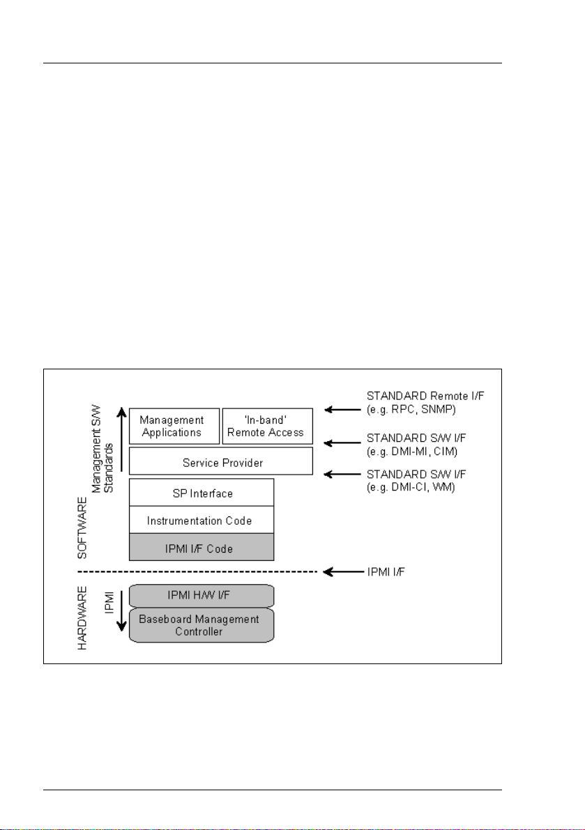
“IPMI is a hardware level interface specification that is ‘management
software neutral’ providing monitoring and control functions that can be
exposed through standard management software interfaces such as
DMI, WMI, CIM, SNMP, etc. As a hardware level interface, it sits at the
bottom of a typical management software stack” [see section "IPMI and
other management standards" on page 22].
iRMC S2/S3 21
Page 22
IPMI - technical background
Advantage
The IPMI specifications ensure the independence of functions for inventory,
logging, recovery and monitoring of a system by the system processor, BIOS or
operating system.
This means that a system can still be involved in platform management when it
is shut down and turned off.
IPMI and other management standards
IPMI is best used in conjunction with system management software running
under the relevant operating system. Integration of the IPMI functionality into the
management functionality offered by a management application and the
operating system results in a powerful platform management environment.
An overview of the relationship between IPMI and the management software
stack is shown by figure 2:
Figure 2: IPMI in the management software stack (source: IPMI specification, see section
"References" on page 29)
22 iRMC S2/S3
Page 23

IPMI - technical background
IPMI, IPMB and ICMB
The IPMI initiative resulted in three central standards:
– IPMI. Intelligent Platform Management Interface Specification
describes the higher-level architecture, the current commands, event
formats, data packets and properties that are used in IPMI-based systems.
– IPMB. Intelligent Platform Management Bus
2
is an I
C based (write only) bus, which provides a standardized connection
between various modules in a common housing.
IPMB can also be used as a standardized interface for remote management
modules.
– ICMB. Intelligent Chassis Management Bus
(Not currently implemented in the ServerView remote management
environment.)
provides a standardized interface for exchange of platform management
information and for control across systems. ICMB is designed in such a way
that it can be implemented with a device that is connected to the IPMB.
IPMI implementation
The core element of an IPMI implementation is the Baseboard Management
Controller (BMC).
The BMC performs the following tasks:
– The BMC organizes the interface between the system management
software and the platform management hardware.
– It provides autonomous functions for monitoring, event logging and recovery
control.
– The BMC acts as a gateway between the system management software and
IPMB.
IPMI allows platform management to be extended: Additional management
controllers can be connected via the IPMB. The IPMB is an I
2
C based serial
bus, which runs between the main modules of the system. It is used for
communication with and between the management controllers.
With the support of multiple management controllers, IPMI provides a scalable
architecture: A complex server system can use multiple controllers for
monitoring different subsystems, e.g. power supplies, hot swap RAID drive
modules etc.
iRMC S2/S3 23
Page 24

IPMI - technical background
In addition, IPMI provides ‘low level’ I2C commands, which can be accessed via
a management controller connected to the IPMB on 'unintelligent' I
2
C modules
that cannot process IPMI commands.
An overview of the fundamental elements of an IPMI implementation is available
in figure 3 on page 25.
24 iRMC S2/S3
Page 25

IPMI - technical background
Figure 3: IPMI block diagram (source: IPMI specification, see section
"References" on page 29)
iRMC S2/S3 25
Page 26

IPMI - technical background
IPMI and “in band” and “out of band” management
In the field of system management, a distinction is made between “in-band” and
“out-of-band” management:
– The term “in-band” management is used when the operating system is
running on the managed server.
– The term “out-of-band” management is used when the operating system is
not running on the managed server, for instance if the hardware is faulty.
As different interfaces are available in an environment with IPMI compatible
systems, you can manage IPMI compatible systems either “in band” or “out of
band”.
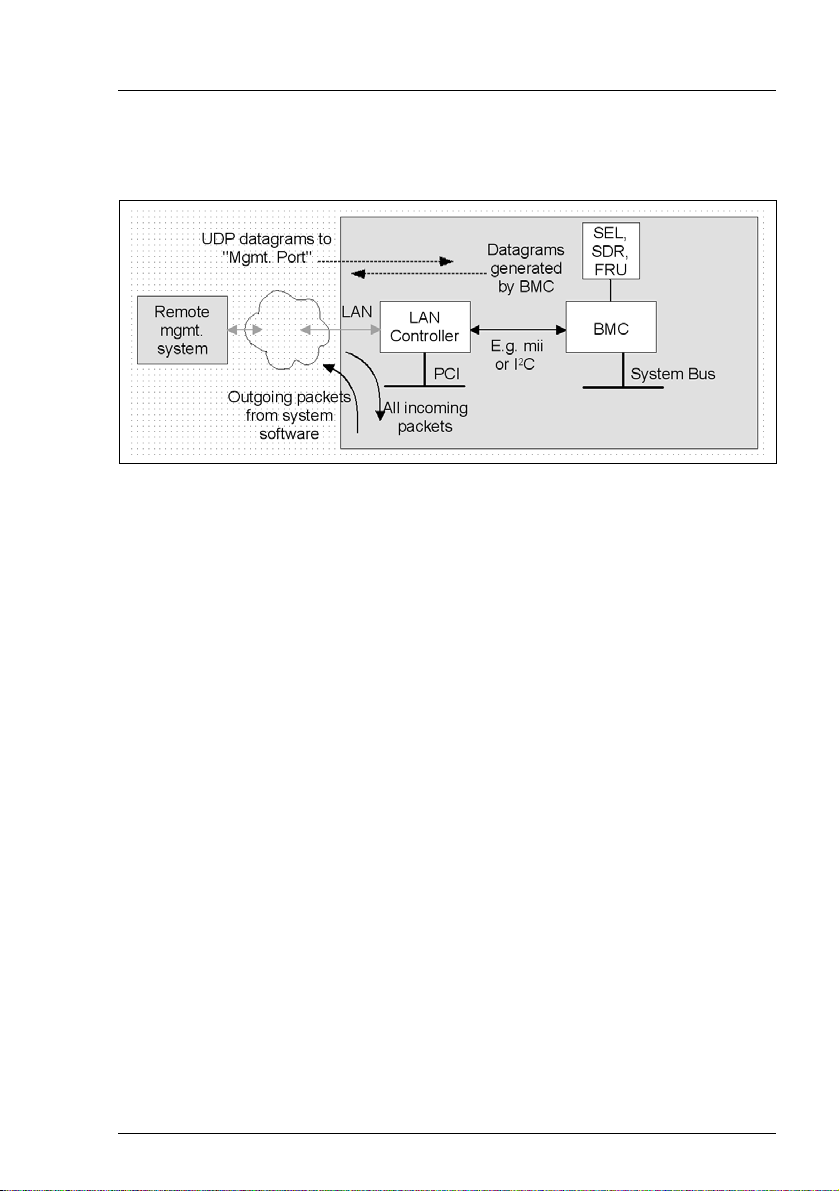
IPMI-over-LAN
“IPMI-over-LAN” is the current name for the specification of the LAN interface in
the IPMI standard. This specification stipulates how IPMI messages can be sent
to or from the BMC of a managed system - encapsulated in RMCP (Remote
Management Control Protocol) data packets. These RMCP data packets are
transferred via an Ethernet LAN connection using the UDP (User Datagram
Protocol) under IPv4 (Internet Protocol Version 4).
The RMCP protocol has been specified to support the management of system
statuses in which the operating system is not running. The RMCP is a simple
inquiry/response protocol.
The interface for such a connection is provided on an onboard LAN controller
assigned to the BMC.
I The interface can only be provided by an on-board LAN controller, not by
an inserted LAN card.
26 iRMC S2/S3
Page 27
IPMI - technical background
Of the two ports that RCMP uses under UDP, the BMC communicates with the
LAN controller via port 623 (primary RMCP Port).
Figure 4: BMC and LAN controller
Serial Over LAN interface (SOL)
“Serial Over LAN” is an interface compliant with the IPMI V2.0 standard, which
controls transfer of serial data over a LAN connection. In particular, SOL
specifies the packet formats and protocols for transferring serial data streams
over a LAN between the serial controller on the managed computer and a
remote workstation. SOL is based on the IPMI-over-LAN specification.
In order to establish an SOL connection, a remote management application first
initiates an IPMI-over-LAN session with the BMC. After this has been done, the
SOL services can be activated from the remote workstation. The data traffic
between the serial controller and the remote workstation is handled over the
same IPMI session as the IPMI commands.
As soon as an SOL connection has been established, data transfer between the
serial controller and the remote workstation is carried out as follows:
– Transfer from the serial controller to the remote workstation:
The data stream issued by the serial controller is partitioned by the BMC,
packaged and then sent to the remote workstation over the LAN.
– Transfer from the remote workstation to the serial controller:
BMC unpacks the characters contained in the packages sent by the remote
workstation and forwards them to the serial controller as a character stream.
iRMC S2/S3 27
Page 28
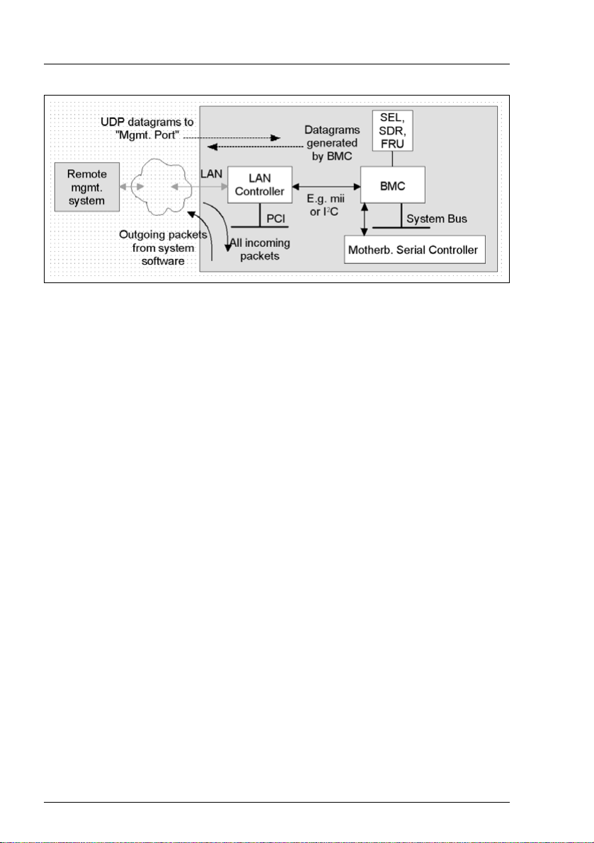
IPMI - technical background
Figure 5: BMC and SOL
The SOL character data is then exchanged between the BMC of the managed
system and the remote workstation as SOL messages. The SOL messages are
encapsulated in RMCP+ data packets and transferred in UDP datagrams over
an Ethernet LAN connection using IPv4 (Internet Protocol Version 4). The
RMCP+ protocol is based on the RMCP protocol, but includes extensions for
encryption, authentication, etc.
Serial over LAN permits “headless” management by console redirection by both
the BIOS and the operating system of the managed server. High-cost
concentrator solutions are not required.
Channel concept under IPMI
‘Channels’ provide the mechanisms with which IPMI messages are routed to
the BMC via various connection carriers. Up to nine channels can be supported.
The system interface and the primary IPMB are fixed. The other seven channels
are available for the implementation.
Channels can be either ‘session based’ or ‘sessionless’. The ‘session’ concept
has two meanings: It is either a concept for user authentication (see the section
"User identifications" on page 29) or a concept for routing multiple IPMI
message streams via a single channel.
Examples of ‘session based’ channels are LAN channels or serial / modem
channels. Examples of ‘sessionless’ channels are the system interface and the
IPMB.
28 iRMC S2/S3
Page 29

Data Center Management Interface (DCMI)
User identifications
For ‘session based’ channels (see the section "Channel concept under IPMI" on
page 28), a user login is necessary. By contrast, the ‘sessionless’ channels
have no user authentication.
Under IPMI, the user configuration is channel specific. Thus, users can have
different privileges depending on whether they are accessing the BMC via the
LAN channel or the serial channel.
References
Information about the IPMI standards can be found on the Internet:
http://developer.intel.com/design/servers/ipmi/index.htm
1.6 DCMI (Data Center Management Interface)
The iRMC S2/S3 supports the DCMI (Data Center Management Interface)
protocol, which is compliant with the IPMI V2.0 standard. DCMI has been
designed to improve manageability and energy efficiency of server systems that
are deployed in large data centers.
To meet the hardware management requirements of servers within data
centers, DCMI supports, among others, the following key features:
– Inventory functions (server identification)
– Power Management and power monitoring
– Power consumption monitoring and control
– Event logging
– Temperature monitoring
Detailed information about DCMI can be found on the DCMI home page:
http://www.intel.com/technology/product/DCMI
iRMC S2/S3 29
Page 30

Changes compared with the previous version
1.7 Changes since the previous versions of the manual
iRMC S2/S3 - integrated Remote Management Controller
(edition Ju
This manual refers to the iRMC S2/S3 firmware version 6.5x and replaces the
following online manual: “iRMC S2/S3 - integrated Remote Management
Controller”, May 2012 edition.
The manual includes the following updates:
● The "0 Watt Technology" feature is described in Chapter "7 iRMC S2/S3 web
interface".
● The former chapter "12 IPMI OEM Commands" has been expanded and is
now an Appendix ("12 Appendix") to the manual, containing the following
sections:
– "12.1 IPMI OEM Commands supported by the iRMC S2/S3" (former
– "12.2 Configuring the iRMC S2/S3 via SCCI and scripted configuration"
ly 2012)
chapter "12 IPMI OEM Commands")
(new section).
iRMC S2/S3 - integrated Remote Management Controller
(edition May 2012)
This manual refers to the iRMC S2/S3 firmware version 6.5x and replaces the
following online manual: “iRMC S2 - integrated Remote Management
Controller”, November 2011 edition.
New iRMC S2/S3 features (described in Chapter "7 iRMC S2/S3 web
interface"):
● Agentless HDD monitoring (iRMC S3 only)
If the managed server supports the "agentless HDD monitoring" feature, the
HDD<n> status of each individual HDD is directly read and reported to the
iRMC S2/S3 via a dedicated lightpath status sensor and thus can be
displayed even in the case no ServerView agents are running.
● Backing up/restoring BIOS settings, flashing BIOS
If the BIOS of the managed server meets the corresponding feature
requirements, the iRMC S2/S3 allows you to perform the following actions:
30 iRMC S2/S3
Page 31

Changes compared with the previous version
– Backing up several BIOS parameters in ServerView® WinSCU XML
format and restoring them in ServerView® WinSCU XML format from a
file.
– Updating BIOS via "upload from file" or via TFTP.
● For some server types, you can select the Low Noise mode under
Power Consumption Options (iRMC S3 only).
iRMC S2/S3 - integrated Remote Management Controller
(edition November 2011)
This manual refers to the iRMC S2/S3 firmware version 5.5x and replaces the
following online manual: “iRMC S2 - integrated Remote Management
Controller”, May 2011 edition.
The following topics are no longer part of this manual:
– Former section "4.4 Global user management for the iRMC S2/S3". As of
SVOM V5.50, this section will be integrated in the "User Management in
ServerView" manual.
– Description of the Server Configuration Manager dialog pages (former
sections 9.2 and the following). Instead, the reader is advised to use the
Online Help of the Server Configuration Manager.
iRMC S2/S3 - integrated Remote Management Controller
(edition May 2011)
This manual refers to the iRMC S2/S3 firmware version 5.5x and replaces the
following online manual: “iRMC S2 - integrated Remote Management
Controller”, April 2011 edition.
The manual applies to both iRMC S2 and iRMC S3. Functional differences in
between the iRMC S2 and the iRMC S3 are pointed out separately in the
manual.
iRMC S2 - integrated Remote Management Controller (edition April 2011)
The April 2011 edition of the iRMC S2 manual refers to the iRMC S2 firmware
version 5.5x and replaces the following online manual: “iRMC S2 - integrated
Remote Management Controller”, July 2010 edition.
● New iRMC S2 features:
iRMC S2/S3 31
Page 32

Changes compared with the previous version
– In addition to the system event log (IPMI SEL), the iRMC S2 now features
an internal event log.
– The iRMC S2 now supports both IPv4 and IPv6 addresses.
– The iRMC S2 now supports the Open DS directory service.
– iRMC S2 Configuration (iRMC S2 firmware settings) can be restored via
the iRMC S2 web interface.
– Email alerting is now also supported for global iRMCS2 user IDs.
● Chapter "5 Advanced Video Redirection (AVR)":
In addition to some minor changes, the menu of the AVR window has been
supplemented with the Power Cont rol entry, allowing you now to power on /
power down / reboot the server directly from the AVR window.
● Chapter "7 iRMC S2 web interface":
– Power Supply page: The Power Supply Redundancy Configuration feature is
available for some server types.
– System Event Log Content page:
GUI language "German":
Event description and resolutions are described in German.
GUI language "Japanese":
Resolutions are described in Japanese.
– The DNS Configuration page now additionally includes the functionality of
the former DHCP configuration page, which is no longer available.
– New / modified pages corresponding to the new iRMC S2 features
mentioned above.
● Chapter "8 Remote Manager":
New / modified menus corresponding to the new iRMC S2 features internal
event log and IPv6 addressing.
● Chapter "9 Server Configuration Manager":
New / modified menu pages corresponding to the new iRMC S2 features
IPv6 addressing and Open DS support.
32 iRMC S2/S3
Page 33

Changes compared with the previous version
1.8 ServerView Suite link collection
Via the link collection, Fujitsu Technology Solutions provides you with numerous
downloads and further information on the ServerView Suite and PRIMERGY
servers.
For ServerView Suite, links are offered on the following topics:
● Forum
● Service Desk
● Manuals
● Product information
● Security information
● Software downloads
● Training
I The downloads include the following:
– Current software versions for the ServerView Suite as well as
additional Readme files.
– Information files and update sets for system software components
(BIOS, firmware, drivers, ServerView agents and ServerView update
agents) for updating the PRIMERGY servers via ServerView Update
Manager or for locally updating individual servers via ServerView
Update Manager Express.
– The current versions of all documentation on the ServerView Suite.
You can retrieve the downloads free of charge from the Fujitsu
Technology Solutions Web server.
For PRIMERGY servers, links are offered on the following topics:
● Service Desk
● Manuals
● Product information
● Spare parts catalogue
Access to the link collection
You can reach the link collection of the ServerView Suite in various ways:
iRMC S2/S3 33
Page 34

Documentation for the ServerView Suite
1. Via ServerView Operations Manager.
Ê Select Help – Links on the start page or on the menu bar.
This opens the start page of the ServerView link collection.
2. Via the ServerView Suite DVD 2 or via the start page of the online
documentation for the ServerView Suite on the Fujitsu Technology Solutions
manual server.
I You access the start page of the online documentation via the
following link:
http://manuals.ts.fujitsu.com
Ê In the selection list on the left, select Industry standard servers.
Ê Click the menu item PRIMERGY ServerView Links.
This opens the start page of the ServerView link collection.
3. Via the ServerView Suite DVD 1.
Ê In the start window of the ServerView Suite DVD 1, select the option
Select ServerView Software Products.
Ê Click Start. This takes you to the page with the software products of the
ServerView Suite.
Ê On the menu bar select Links.
This opens the start page of the ServerView link collection.
1.9 Documentation for ServerView Suite
The documentation for the ServerView Suite can be found on the ServerView
Suite DVD 2 supplied with each server system.
The documentation can also be downloaded free of charge from the Internet.
You will find the online documentation at http://manuals.ts.fujitsu.com under the
link Industry standard servers.
34 iRMC S2/S3
Page 35

Notational conventions
1.10 Notational conventions
The meanings of the symbols used in this manual are as follows:
V Warning This symbol is used to draw attention to risks which
may represent a health hazard or which may lead
to data loss or damage to the hardware.
I This symbol is used to highlight important
information and tips.
Ê This symbol indicates an action which you must
carry out.
Text in italics In running text, commands, menu items, and the
names of buttons, options, files and paths are
shown in italics.
<text> Indicates variables which must be replaced by
current values.
Monospaced font Output from the system is shown in monospaced
font.
Monospaced font
Bold monospaced font
[square brackets] Indicate optional entries.
{braces} Indicate a list of alternatives separated by “|”.
[Keyboard] [symbols] Keys are shown as they appear on the keyboard. If
Commands to be entered at the keyboard are
shown in bold, monospaced font.
uppercase characters are to be entered explicitly,
this is indicated for instance by [SHIFT] - [A] for A.
If two keys are to be pressed simultaneously, this
is indicated by a hyphen between the two keyboard
symbols.
Table 2: Notational conventions
If reference is made to passages elsewhere in this manual, the title of the
chapter or section is named and the page number given refers to the start of the
section.
iRMC S2/S3 35
Page 36

Notational conventions
36 iRMC S2/S3
Page 37

2 Logging on to the iRMC S2/S3 for
the first time
The factory default settings of the iRMC S2/S3 allow you to log in to the
iRMC S2/S3 for the first time without the need for any configuration activities.
2.1 Requirements
On the remote workstation:
– Windows: Internet Explorer as of Version 7.x:
Linux: Mozilla Firefox 3.x.
– For console redirection:
Sun Java Virtual Machine Version 1.5.0_06 or higher.
In your network:
– You must have a DHCP server in your network.
– If you want to log in with a symbolic name rather than an IP address at the
iRMC S2/S3 web interface, the DHCP server in your network must be
configured for dynamic DNS.
– DNS must be configured. Otherwise you must ask for the IP address.
iRMC S2/S3 37
Page 38

iRMC S2/S3 factory defaults
2.2 iRMC S2/S3 factory defaults
The firmware of the iRMC S2/S3 provides a default administrator ID and a
default DHCP name for the iRMC S2/S3.
Default administrator ID:
Administrator ID: admin
Password: admin
I Both the administrator ID and the password are case-sensitive.
For reasons of security, it is recommended that you create a new
administrator account once you have logged in, and then delete the
default administrator account or at least change the password for the
account (see section "User Management" on page 263).
Default DHCP name of the iRMC S2/S3
The default DHCP name of the iRMC S2/S3 uses the following pattern:
IRMC<SerialNumber>
I The serial number corresponds to the last 3 bytes of the MAC address of
the iRMC S2/S3. You can take the MAC address of the iRMC S2/S3 from
the label on your PRIMERGY server.
After you have logged in, the MAC address of the iRMC S2/S3 can be
found as a read-only entry above the fields on the page Network Interface
(see page 239).
38 iRMC S2/S3
Page 39

Logging into the iRMC S2/S3 web interface
2.3 Logging into the iRMC S2/S3 web interface
Ê Open a web browser on the remote workstation and enter the DNS name or
IP address of the iRMC S2/S3.
I You can take the DNS name of the iRMC S2/S3 from the label on your
PRIMERGY server.
The following login prompt appears:
Figure 6: Login prompt for the iRMC S2/S3 web interface
I If the login prompt does not appear, check the LAN connection (see
section "Testing the LAN interface" on page 47).
Ê Type in the data for the default administrator account.
User name: admin
Password: admin
Ê Click OK to confirm your entries.
The iRMC S2/S3 web interface opens showing the System Information page (see
page 146).
iRMC S2/S3 39
Page 40

Page 41

3 Configuring the iRMC S2/S3
The following tools are available for configuring the iRMC S2/S3:
– BIOS / TrustedCore / UEFI setup utility (see page 44)
– iRMC S2/S3 web interface (see page 135)
– Server Configuration Manager (see page 347)
This chapter provides you with information about the following topics:
– Configuring the LAN interface of the iRMC S2/S3 using the BIOS /
TrustedCore / UEFI setup utility (see page 44).
– Configuring text console redirection via LAN using the BIOS / TrustedCore /
UEFI setup utility (see page 48).
– Configuring the serial interface of the iRMC S2/S3 using the BIOS /
TrustedCore / UEFI setup utility (see page 57).
– Configuring the iRMC S2/S3 over the web interface (for an overview, see
page 63).
3.1 Configuring the LAN interface of the iRMC S2/S3
This section describes:
– Requirements for configuring the LAN interface
– Configuring the LAN interface in the BIOS / TrustedCore
– Testing the LAN interface
®
/ UEFI setup utility
I "Spanning Tree" tree for the connection of the iRMC S2/S3 must be
deactivated (e.g. Port Fast=enabled; Fast Forwarding=enabled).
iRMC S2/S3 41
Page 42

Configuring the LAN interface of the iRMC S2/S3
3.1.1 Prerequisites
Note the following requirements with respect to configuring the IP address:
– The LAN cable must be connected to the correct port. (see section
"Connected to the correct LAN port?" on page 42).
– Interaction between the IP addresses of the iRMC S2/S3 and the system
(see the section "Interaction between the IP addresses of the iRMC S2/S3
and the system" on page 43).
3.1.1.1 Connected to the correct LAN port?
The interface for a LAN connection is provided on an onboard LAN controller
assigned to the iRMC S2/S3 (see also figure 4 on page 27).
Depending on the server type, the system board of a PRIMERGY server
provides two or three LAN interfaces. The ports marked with a wrench symbol
are assigned to the iRMC S2/S3 (in figure 7, for example, these are port 1 and
the top left-hand port).
I Check that the LAN cable is connected to the correct port.
Depending on the type of PRIMERGY server, different ports may be
marked with the wrench symbol.
Dedicated Service / Management LAN
(port exclusively for the
iRMC S2/S3; with the iRMC S3
a LAN speed up to 1000 MBit/s
is available, depending on the
server hardware.)
Figure 7: Ports for the iRMC S2/S3 (indicated by wrench symbol)
42 iRMC S2/S3
(1)
LAN (port exclusively
(2)
for the system)
Shared LAN
(iRMC S2/S3 and system)
Page 43

Configuring the LAN interface of the iRMC S2/S3
3.1.1.2 Interaction between the IP addresses of the iRMC S2/S3 and the system
The LAN controller of the PRIMERGY server requires a separate IP address for
the iRMC S2/S3 in order to ensure that data packets are reliably transferred to
the iRMC S2/S3 (and not to the operating system).
The IP address of the iRMC S2/S3 must be different from that of the system
(operating system).
3.1.1.3 Access from a different subnet
If the remote workstation accesses the iRMC S2/S3 of the managed server from
a different subnet and DHCP is not used, you must configure the gateway.
3.1.2 Configuring the LAN interface: Configuration tools
You can configure the iRMC S2/S3’s LAN interface in a number of ways:
Depending on the type of the PRIMERGY server
– using the BIOS / TrustedCore / UEFI setup utility (see page 44),
– iRMC S2/S3 web interface (see section "Network Settings - Configure the
LAN parameters" on page 238),
– using the Server Configuration Manager (see chapter "Configuring
iRMC S2/S3 using the Server Configuration Manager" on page 347).
iRMC S2/S3 43
Page 44

Configuring the LAN interface of the iRMC S2/S3
3.1.3 Configuring the LAN interface using the BIOS / TrustedCore / UEFI setup utility
You can configure the iRMC S2/S3’s LAN interface using the BIOS /
TrustedCore / UEFI setup utility:
– Use the BIOS / TrustedCore setup utility to configure the LAN interface of the
iRMC S2.
– Use the UEFI (Unified Extensible Firmware Interface) setup utility to
configure the LAN interface of the iRMC S3.
3.1.3.1 Configuring the LAN interface of the iRMC S2 by using the BIOS / TrustedCore setup utility
I IPv6 addresses are not supported in the BIOS / TrustedCore setup utility.
Ê Call the BIOS / TrustedCore setup utility of the managed server. Do this by
pressing [F2] while the server is booting.
Ê Call the LAN parameter configuration menu:
–BIOS: Advanced – IPMI – LAN Settings
– TrustedCore: Server – IPMI – LAN Settings
Figure 8: LAN Settings menu (shown here for the TrustedCore setup utility)
44 iRMC S2/S3
Page 45

Configuring the LAN interface of the iRMC S2/S3
Ê Configure the following settings:
Service LAN
Set the value to Enabled.
Service LAN Port
The Service setting is recommended.
I The Service setting is mandatory for the Type TX150 S6
PRIMERGY server.
DHCP
If you enable DHCP, the iRMC S2 gets its LAN settings autonomously
from a DHCP server on the network. In this case, the values for Local
IP Address, Subnet Mask, etc. are set automatically.
I Do not activate the DHCP option if no DHCP server is
available. If you activate the DHCP option and there is no
DHCP server available, the iRMC S2 goes into a search loop
(i.e. it constantly searches for a DHCP server).You can specify
that the DHCP and DNS services are to be used after initial
installation, using the iRMC S2 web interface, for instance (see
section "DNS Configuration - Configuring DNS for the
iRMC S2/S3" on page 249).
By default, the following name is passed to the DHCP server
on initial installation of the iRMC S3:
iRMC<last 3 bytes of the MAC address>.
Local IP Address
Enter the IP address you have determined for the iRMC S2 of the
managed system.
Subnet Mask
Enter the subnet mask for the network. the iRMC S2 is connected to.
Gateway Address
Specify the IP address of the gateway of the network the iRMC S2 is
connected to.
Ê Save the settings.
iRMC S2/S3 45
Page 46

Configuring the LAN interface of the iRMC S2/S3
Ê If you want to use console redirection on the iRMC S2 continue with section
"Configuring text console redirection for the iRMC S2" on page 49.
If you do not want to use text console redirection on the iRMC S2, exit the
BIOS/TrustedCore setup and continue with the next section "Testing the LAN
interface".
3.1.3.2 Configuring the LAN interface of the iRMC S3 by using the UEFI setup Utility
Ê Call the UEFI setup utility of the managed server. Do this by pressing [F2]
while the server is booting.
Ê Call the iRMC LAN parameter configuration menu:
Server Mgmt – iRMC LAN Parameters Configuration
Figure 9: iRMC LAN Parameters Configuration Menu
46 iRMC S2/S3
Page 47

Configuring the LAN interface of the iRMC S2/S3
Ê Configure the following settings:
Management LAN
Set the value to Enabled.
Management LAN Port
The Management setting is recommended.
I For details on configuring the remaining settings see section
"Network Settings - Configure the LAN parameters" on page 238
and/or refer to the manual "BIOS (Aptio) Setup Utility" manual
corresponding to your server.
Ê Save the settings.
Ê If you want to use console redirection on the iRMC S3, continue with section
"Configuring text console redirection for the iRMC S3" on page 53.
If you do not want to use text console redirection on the iRMC S3, exit the
UEFI setup and continue with the next section "Testing the LAN interface".
3.1.4 Testing the LAN interface
You can test the LAN interface as follows:
Ê Use a web browser to attempt to log into the iRMC S2/S3 web interface. If
no login prompt appears, it is probable that the LAN interface is not working.
Ê Test the connection to the iRMC S2/S3 with a ping command.
iRMC S2/S3 47
Page 48

Configuring text console redirection via LAN
3.2 Configuring text console redirection via LAN using the BIOS / TrustedCore / UEFI setup utility
Text console redirection will be available depending on the configuration of text
console redirection and on the operating system of the server
– either for the duration of the BIOS POST phase only or
– beyond the BIOS POST phase while the operating system is running.
This section describes:
– Configuration of text console redirection via LAN using the BIOS /
TrustedCore setup utility (for iRMC S2)
– Configuration of text console redirection via LAN using the UEFI setup utility
(for iRMC S3)
– Special requirements of the operating system used that you need to take
account of if you also want to use console redirection while the operating
system is running.
I You can also configure text console redirection via LAN using the
iRMC S2/S3 web interface (see section "BIOS Text Console - Configure
and start text console redirection" on page 292).
48 iRMC S2/S3
Page 49

Configuring text console redirection via LAN
3.2.1 Configuring text console redirection for the iRMC S2
Ê Call the BIOS / TrustedCore setup utility of the managed server. Do this by
pressing [F2] while the server is booting.
Settings in the Peripheral Configuration menu
Ê Call the Peripheral Configuration menu:
Advanced – Peripheral Configuration
Figure 10: Peripheral Configuration menu (as it appears in the TrustedCore setup utility)
Ê Configure the following settings:
Serial 1
Set the value to Enabled.
Serial 1 Address
Accept the first value pair proposed.
Serial Multiplexer
Set the value to iRMC.
iRMC S2/S3 49
Page 50

Configuring text console redirection via LAN
Settings in the Console Redirection menu
Ê Call the Console Redirection menu:
Server – Console Redirection
I The appearance of the Console Direction menu varies depending on
the setup utility (BIOS or TrustedCore) you are using.
Ê Make the following settings in the BIOS setup utility:
Figure 11: Console Redirection menu (as it appears in the BIOS setup utility)
Console Redirection
Set the value to Enabled.
Port
Set the value to Serial 1.
Baud Rate
Specify the baud rate.
Protocol
Leave this setting unchanged. (The setting depends on the terminal
type used.)
Flow Control
Leave this setting unchanged. (The setting depends on the terminal
type used.)
50 iRMC S2/S3
Page 51

Configuring text console redirection via LAN
Mode
This setting affects the behavior of console redirection while the
operating system is running (after the POST phase has completed) see section "Using console redirection while the operating system is
running" on page 55:
Standard
Console redirection is terminated after the BIOS POST phase.
Enhanced
Console redirection continues to be available after the BIOS
POST phase.
Ê Make the following settings in the TrustedCore setup utility:
Figure 12: Console Redirection menu (as it appears in the TrustedCore setup utility)
Com Port Address
Set the value to On-board COM A.
Baud Rate
Specify the baud rate.
Console Type
Leave this setting unchanged. (The setting depends on the terminal
type used.)
iRMC S2/S3 51
Page 52

Configuring text console redirection via LAN
Flow Control
The setting depends on the terminal type used. The settings must be
the same on both terminal and managed server.
Continue C.R. after POST:
This setting affects the behavior of console redirection while the
operating system is running (after the POST phase has completed) see section "Using console redirection while the operating system is
running" on page 55:
Off
Console redirection is terminated after the BIOS POST phase.
On
Console redirection continues to be available after the BIOS
POST phase.
Exiting the BIOS / TrustedCore setup utility
Ê Save your settings and exit the BIOS/TrustedCore setup utility.
Ê Continue with section "Testing the LAN interface" on page 47.
52 iRMC S2/S3
Page 53

Configuring text console redirection via LAN
3.2.2 Configuring text console redirection for the iRMC S3
Ê Call the UEFI setup utility of the managed server. Do this by pressing [F2]
while the server is booting.
Ê Call the Server Mgmt menu:
Figure 13: Server Mgmt Menu
Ê Make the following settings:
Serial Multiplexer
Set the value to iRMCS3.
iRMC S2/S3 53
Page 54

Configuring text console redirection via LAN
Ê Call the Console Redirection menu:
Figure 14: Console Redirection menu
Ê Make the following settings in the Console Redirection menu:
Console Redirection
Set the value to Serial 1. In this case, the terminal uses the first serial
interface.
Baud Rate
Specify the baud rate.
Protocol
Leave this setting unchanged. (The setting depends on the terminal
type used.)
Flow Control
The setting depends on the terminal type used. The settings must be
the same on both terminal and managed server.
Exiting the UEFI setup utility
Ê Save your settings and exit the UEFI setup utility.
Ê Continue with section "Testing the LAN interface" on page 47.
54 iRMC S2/S3
Page 55

Configuring text console redirection via LAN
3.2.3 Using console redirection while the operating system is running
Depending on the operating system used on the managed server, you can
continue to use console redirection after the BIOS POST phase.
DOS
The BIOS setting for console redirection mode must be set as follows (see
section "Settings in the Console Redirection menu" on page 50):
– BIOS setup utility: Mode: Enhanced
– TrustedCore setup utility: Continue C.R. after POST: On
Windows Server 2003 / 2008
I If activated during Windows installation, console redirection is thereby
automatically configured.
If console redirection is activated after Windows installation has
completed, you must configure console redirection manually.
Windows Server 2003 / 2008 handles console redirection automatically after the
POST phase. No further settings are necessary. While the operating system is
booting, the Windows Server 2003 SAC console is transferred:
Figure 15: Windows Server 2003 SAC console
iRMC S2/S3 55
Page 56

Configuring text console redirection via LAN
Linux
You must configure a Linux operating system in such a way that it handles
console redirection after the POST phase. Once it has been configured, you
have unrestricted access from the remote workstation.
Settings required
The settings may differ between program versions.
SuSe and RedHat
Add the following line to the end of the file /etc/inittab:
xx:12345:respawn:/sbin/agetty <baud-rate> ttyS0
RedHat
Insert the following kernel boot parameter in the file /etc/grub.conf:
console=ttyS0,<baud-rate> console=tty0
SuSE
Insert the following kernel boot parameter in the file /boot/grub/menu.lst :
console=ttyS0,<baud-rate> console=tty0
56 iRMC S2/S3
Page 57

Configuring and using the serial interface of the iRMC S2/S3
3.3 Configuring and using the serial interface
of the iRMC S2/S3
The serial interface of the iRMC S2/S3 offers you the following possibilities:
– You can use the terminal application Remote Manager (Serial) over a null
modem cable (see section "Using the Remote Manager (Serial) interface"
on page 62).
– In the case of an iRMC S2, you can forward alerts via modem. You can
configure alerting via modem using the web interface of the iRMC S2 (see
section "Serial / Modem Alerting - Configure alerting via modem" on
page 255).
iRMC S2/S3 57
Page 58

Configuring and using the serial interface of the iRMC S2/S3
3.3.1 Configuring the serial interface of the iRMC S2
Ê Call the BIOS / TrustedCore setup utility of the managed server. Do this by
pressing [F2] while the server is booting.
Ê Call the Peripheral Configuration menu to configure the serial port:
Advanced – Peripheral Configuration
Figure 16: Peripheral Configuration menu (as it appears in the TrustedCore setup utility)
Ê Configure the following settings:
Serial 1
Set the value to Enabled.
Serial 1 Address
Accept the first value pair proposed.
Serial Multiplexer
Set the value to iRMC.
58 iRMC S2/S3
Page 59

Configuring and using the serial interface of the iRMC S2/S3
The following values are not shown in the menu and are preset (see
page 62, “Terminal program (VT100+)”):
Bits per second
9600
Data bits
8
Parity
None.
Stop bits
1
Flow Control
None
Exiting the BIOS / TrustedCore setup utility
Ê Save your settings and exit the BIOS/TrustedCore setup utility.
Ê Continue with section "Testing the LAN interface" on page 47.
iRMC S2/S3 59
Page 60

Configuring and using the serial interface of the iRMC S2/S3
3.3.2 Configuring the serial interface using of the iRMC S3
Ê Call the UEFI setup utility of the managed server. Do this by pressing [F2]
while the server is booting.
Ê Call the Server Mgmt menu:
Figure 17: Server Mgmt menu
Ê Configure the following settings:
Serial Multiplexer
Set the value to iRMCS3.
Ê Call the Serial Port 1 Configuration menu to configure the serial port:
Advanced – Super IO Configuration – Serial Port 1 Configuration:
60 iRMC S2/S3
Page 61

Configuring and using the serial interface of the iRMC S2/S3
Figure 18: Serial Port 1 Configuration menu
Ê Configure the following settings:
Serial Port
Set the value to Enabled.
Device Settings
Displays the base I/O address and the interrupt used to access the
corresponding serial port, e.g. IO=3F8h; IRQ=4.
Accept the value pair proposed.
The following values are not shown in the menu and are preset (see
page 62, “Terminal program (VT100+)”):
Bits per second
9600
Data bits
8
Parity
None.
Stop bits
1
iRMC S2/S3 61
Page 62

Configuring and using the serial interface of the iRMC S2/S3
Flow Control
None
Exiting the UEFI setup utility
Ê Save your settings and exit the UEFI setup utility.
Ê Continue with section "Testing the LAN interface" on page 47.
3.3.3 Using the Remote Manager (Serial) interface
If you connect a computer over a null modem cable and start a terminal program
(VT100+) on this computer, you can access the Remote Manager (Serial)
terminal program. The Remote Manager (Serial) interface is identical to the
Remote Manager interface (see chapter "iRMC S2/S3 via Telnet/SSH (Remote
Manager)" on page 321).
Prerequisites
On the managed server:
The Serial Multiplexer BIOS setting must be configured on the iRMC (see
section "Configuring the serial interface of the iRMC S2" on page 58).
Terminal program (VT100+):
Configure the following port settings for the terminal program:
Bits per second
Set the value to 9600.
Data bits
Set the value to 8.
Parity
Set the value to None.
Stop bits
Set the value to 1.
Flow Control
Set the value to None.
62 iRMC S2/S3
Page 63

Configuring the iRMC S2/S3 over the iRMC S2/S3 web interface
3.4 Configuring the iRMC S2/S3 over the
iRMC S2/S3 web interface
Ê Start the iRMC S2/S3 web interface (see section "Logging into the
iRMC S2/S3 web interface" on page 136).
3.4.1 Configuring the LAN parameters
Ê In the navigation area, click Network Settings (see section "Network Settings
- Configure the LAN parameters" on page 238).
Configuring the LAN settings
Ê Configure the LAN settings on the Network Interface page. See the section
"Network Interface Settings - Configure Ethernet settings on the iRMC
S2/S3" on page 239 for the settings required.
Configuring ports and network services
Ê Configure the ports and network services on the Ports and Network Services
page. See the section "Ports and Network Services - Configuring ports and
network services" on page 245 for the settings required.
Configuring DHCP/DNS (Dynamic DNS)
Ê Configure the DHCP and DNS settings in the DNS Configuration page. See
the section "DNS Configuration - Configuring DNS for the iRMC S2/S3" on
page 249 for the settings required.
iRMC S2/S3 63
Page 64

Configuring the iRMC S2/S3 over the iRMC S2/S3 web interface
3.4.2 Configuring alerting
The pages for configuring alerting are grouped in the navigation area under
Alerting (see section "Alerting - Configure alerting" on page 253).
Configuring alert forwarding over SNMP
Ê In the navigation area, click SNMP Traps. The SNMP Traps page appears.
Ê Configure SNMP trap forwarding. See the section "SNMP Trap Alerting -
Configure SNMP trap alerting" on page 254 for the settings required.
Configuring alert forwarding to a mobile phone via modem
(only with the iRMC S2)
Ê In the navigation area, click Serial / Modem. The Serial / Modem Alerting page
appears.
Ê Configure alert forwarding via modem. See the section "Serial / Modem
Alerting - Configure alerting via modem" on page 255 for the settings
required.
Configuring email notification (email alerting)
Ê In the navigation area, click Email. The Email Alerting page appears.
Ê Configure email alerting. See the section "Email Alerting - Configure email
alerting" on page 257 for the settings required.
3.4.3 Configuring text console redirection
Ê Configure text console redirection in the BIOS Text Console window. See the
section "BIOS Text Console - Configure and start text console redirection"
on page 292 for the settings required.
64 iRMC S2/S3
Page 65

4 User management for the
iRMC S2/S3
User management for the iRMC S2/S3 uses two different types of user
identifications:
– Local user identifications are stored locally in the iRMC S2/S3’s non-
volatile storage and are managed via the iRMC S2/S3 user interfaces.
– Global user identifications are stored in the central data store of a
directory service and are managed via this directory service’s interfaces.
The following directory services are currently supported for global
iRMC S2/S3 user management:
–Microsoft
–Novell
– OpenLDAP
– OpenDS
This chapter provides information on the following topics:
– User management concept for the iRMC S2/S3
– User permissions
– Local user management on the iRMC S2/S3
®
Active Directory
®
eDirectory
I For detailed information on the global user management using the
individual directory services, please refer to the "User Management in
ServerView" manual.
iRMC S2/S3 65
Page 66

Concept
4.1 User management concept for the iRMC S2/S3
User management for the iRMC S2/S3 permits the parallel administration of
local and global user identifications.
When validating the authentication data (user name, password) which users
enter when logging in to one of the iRMC S2/S3 interfaces, iRMC S2/S3
proceeds as follows (see also figure 19 on page 67):
1. The iRMC S2/S3 compares the user name and password with the locally
stored user identifications:
● If the user is authenticated successfully by iRMC S2/S3 (user name and
password are valid) then the user can log in.
● Otherwise, the iRMC S2/S3 continues the verification with step 2.
2. The iRMC S2/S3 authenticates itself at the directory service via LDAP with
a user name and password, determines the user rights by means of an
LDAP query and checks whether the user is authorized to work with these
at the iRMC S2/S3.
66 iRMC S2/S3
Page 67

Concept
iRMC S2/S3 web
interface
Login
SSH
Login
SSHSSL
User name, password
SSL
SSH
iRMC S2/S3
local user identifications
SSL
User name, password
SSL
Te ln e t
Login
Serial
interface
Login
LDAP login
Bild 19: Login authentication via the iRMC S2/S3
Directory service
Global user identifications
I Although optional, the use of SSL for the LDAP connection between the
iRMC S2/S3 and directory service is recommended. An SSL-secured
LDAP connection between iRMC S2/S3 and the directory service
guarantees secure data exchange, and in particular the secure transfer
of the user name and password data.
SSL login via the iRMC S2/S3 web interface is only required if LDAP is
active (LDAP enable option, see page 274).
iRMC S2/S3 67
Page 68

User permissions
4.2 User permissions
The iRMC S2/S3 distinguishes between two mutually complementary types of
user permissions:
– Channel-specific privileges (via assignment to channel-specific permission
groups)
– Permissions to use special iRMC S2/S3 functions
I The privileges and permissions required for the use of the individual
iRMC S2/S3 functions are described
– for the iRMC S2/S3-web interface, on page 138,
– for the Remote Manager, on page 330.
Channel-specific privileges (channel-specific permission groups)
The iRMC S2/S3 assigns each user identification to one of the following four
channel-specific permission groups:
–users
– Operator
– Administrator
–OEM
Since iRMC S2/S3 assigns these permissions on a channel-specific basis,
users can have different permissions, depending on whether they access the
iRMC S2/S3 over the LAN interface or the serial interface.
The scope of permissions granted increases from User (lowest permission level)
through Operator and Administrator up to OEM (highest permission level).
I The permission groups correspond to the IPMI privilege level. Certain
permissions (e.g. for Power Management) are associated with these
groups or privilege levels.
68 iRMC S2/S3
Page 69

User permissions
Permissions to use special iRMC S2/S3 functions
In addition to the channel-specific permissions, you can also individually assign
users the following permissions:
– Configure User Accounts
Permission to configure local user identifications
– Configure iRMC S2/S3 Settings
Permission to configure the iRMC S2/S3 settings.
– Video Redirection Enabled
Permission to use Advanced Video Redirection (AVR) in “View Only” and
“Full Control” mode
– Remote Storage Enabled
Permission to use the Remote Storage functionality
Preconfigured user ID
The firmware of the iRMC S2/S3 provides a default administrator ID for the
iRMC S2/S3 which possesses all permissions:
Administrator ID: admin
Password: admin
I Both the administrator ID and the password are case-sensitive in the
case of local users.
It is urgently recommended that you create a new administrator account
as soon as possible once you have logged in, and then delete the default
administrator account or at least change the password for the account
(see section "User Management" on page 263).
iRMC S2/S3 69
Page 70

Local user management for the iRMC S2/S3
4.3 Local user management for the iRMC S2/S3
The iRMC S2/S3 possesses its own local user management. Up to 16 users to
be configured with passwords and be assigned various rights depending on the
user groups they belong to. The user identifications are stored in the
iRMC S2/S3’s local, non-volatile storage.
The following options are available for user management on the iRMC S2/S3:
– User management via the web interface
– User management via the Server Configuration Manager
4.3.1 Local user management using the iRMC S2/S3 web interface
I User management on the iRMC S2/S3 requires Configure User Accounts
permission.
You can view a list of configured users under the web interface. You can also
configure new users, change the configuration of existing users and remove
users from the list.
Ê Start the iRMC S2/S3 web interface (see section "Logging into the
iRMC S2/S3 web interface" on page 136).
Showing the list of configured users
Ê In the navigation area, click the User Management - iRMC S2/S3 User function.
The User Management page opens containing a list of configured users (see
page 264). Here, you can delete users and call the page for configuring new
users.
This page is described in section "User Management" on page 263.
70 iRMC S2/S3
Page 71

Local user management for the iRMC S2/S3
Configuring new users
Ê On the User Management page, click the New User button.
The New User Configuration page opens. This page allows you to configure
the basic settings for the new user. This page is described in section "New
User Configuration - Configuring a new user" on page 265.
Modifying the configuration of a user
Ê On the User Management page, click the name of the user whose
configuration parameters you want to change.
The User “<name>” Configuration page opens showing the settings for the
selected user. Here, you can change the configuration parameters for the
new user. This page is described in section "User “<name>” Configuration -
User configuration (details)" on page 266.
Deleting users
Ê On the User Management page, click on the Delete button in the same line as
the user to be deleted.
4.3.2 Local user management via the Server Configuration Manager
I Prerequisite:
The current ServerView agents must be installed on the managed server.
I User management on the iRMC S2/S3 requires Configure User Accounts
permission.
User management via the Server Configuration Manager largely conforms to
user management using the iRMC S2/S3 web interface.
In chapter "Configuring iRMC S2/S3 using the Server Configuration Manager"
on page 347 is described how to start the Server Configuration Manager.
For details on the individual Configuration Manager dialogs, please refer to the
online help of the Server Configuration Manager.
iRMC S2/S3 71
Page 72

Local user management for the iRMC S2/S3
4.3.3 SSHv2 public key authentication for iRMC S2/S3 users
In addition to authentication by means of a user name and password, the
iRMC S2/S3 also supports SSHv2-based public key authentication using pairs
of public and private keys for local users. To implement SSHv2 public key
authentication, the SSHv2 key of an iRMC S2/S3 user is uploaded to the
iRMC S2/S3 and the iRMC S2/S3 user uses their private key with the program
PuTTY or the OpenSSH client program ssh, for example.
The iRMC S2/S3 supports the following types of public keys:
– SSH DSS (minimum requirement)
– SSH RSA (recommended)
The public SSHv2 keys that you upload to the iRMC S2/S3 can be available
either in RFC4716 format or in OpenSSH format (see page 84).
Public key authentication
In outline, public key authentication of a user on the iRMC S2/S3 happens as
follows:
The user who wishes to log into the iRMC S2/S3 creates the key pair:
– The private key is read-protected and remains on the user's computer.
– The user (or administrator) uploads the public key to the iRMC S2/S3.
If the configuration allows this, the user can now log into the iRMC S2/S3
extremely securely and without the need to enter a password. The user is only
responsible for keeping their private key secret.
The following steps are necessary to set up private key authentication. They are
described in the subsequent sections:
1. Creating the public and private SSHv2 keys with the program PuTTYgen or
ssh-keygen and saving them in separate files (see page 73).
2. Loading the public SSHv2 key onto the iRMC S2/S3 from a file
(see page 77).
3. Configuring the program PuTTY or ssh for SSHv2 access to the iRMC S2/S3
(see page 79).
72 iRMC S2/S3
Page 73

Local user management for the iRMC S2/S3
4.3.3.1 reating public and private SSHv2 keys
You can create public and private SSHv2 keys
– with the program PuTTYgen or
– with the OpenSSH client program ssh-keygen.
Creating the public and private SSHv2 keys with PuTTYgen
Proceed as follows:
Ê Start PuTTYgen on your Windows computer.
The following window appears when PuTTYgen is started:
Bild 20: PuTTYgen: Creating new private and public SSHv2 keys
Ê Under Para me te rs , select the key type SSH-2RSA and click Generate to start
generation of the keys.
The progress of the generation operation is then displayed under Key (see
figure 21 on page 74).
iRMC S2/S3 73
Page 74

Local user management for the iRMC S2/S3
Bild 21: PuTTYgen: Creating a new key pair (progress bar).
Ê Move the mouse pointer over the blank area of the progress display to
increase the randomness of the generated keys.
When the keys have been generated, PuTTYgen displays the key and the
fingerprint of the public SSHv2 key:
Bild 22: PuTTYgen: Creating a new private SSHv2 key (progress bar).
Ê Click Save public key to save the public SSHv2 key to a file. You can upload
the public key to the iRMC S2/S3 from this file (see page 77).
Ê Click Save private key to save the private SSHv2 key to a file for use with
PuTTY (see page 79).
74 iRMC S2/S3
Page 75

Local user management for the iRMC S2/S3
Creating the public and private SSHv2 keys with ssh-keygen
I If it is not already pre-installed in the Linux distribution you are using, you
can obtain OpenSSH from http://www.openssh.org.
You will find a detailed description of the operands in the OpenSSH
OpenSSH manual pages under http://www.openssh.org/manual.html
Proceed as follows:
Ê Call ssh-keygen to generate an RSA key pair:
ssh-keygen -t rsa
ssh-keygen logs the progress of the key generation operation. ssh-keygen
queries the user for the file name under which the private key is to be stored
and for the passphrase for the private key. ssh-keygen stores the resulting
private and public SSHv2 keys in separate files and displays the fingerprint
of the public key.
Example: Generating an RSA key pair with ssh -keygen
1
2
3
4
5
iRMC S2/S3 75
Page 76

Local user management for the iRMC S2/S3
Explanation:
1. ssh-keygen requests the file name under which the SSHv2 key is to be
saved. If you press [Enter] to confirm without entering a file name,
ssh-keygen uses the default file name id_rsa.
2. ssh-keygen requests you to enter a passphrase (and to confirm it) that
is used to encrypt the private key. If you press [Enter] to confirm
without entering a passphrase, ssh-keygen does not use a passphrase.
3. ssh-keygen informs the user that the newly generated private SSHv2
key has been saved in the file /.ssh/id_rsa.
4. ssh-keygen informs the user that the newly generated public SSHv2
key has been saved in the file /.ssh/id_rsa.pub.
5. ssh-keygen displays the fingerprint of the public SSHv2 key and the
local login to which the public key belongs.
76 iRMC S2/S3
Page 77

Local user management for the iRMC S2/S3
4.3.3.2 Loading the public SSHv2 key onto the iRMC S2/S3 from a file
Proceed as follows:
Ê Under the iRMC S2/S3 web interface, open the detailed view for the required
browser (in this case user3) iRMC S2/S3 User Management page:
(1)
(2)
Bild 23: iRMC S2/S3 web interface: Loading the public SSHv2 key onto the iRMC S2/S3
Ê Click Browse in the group User SSHv2 public key upload from file (1) and
navigate to the file containing the required public key (2).
iRMC S2/S3 77
Page 78

Local user management for the iRMC S2/S3
Ê Click Upload to load the public key onto the iRMC S2/S3.
After the key has been successfully uploaded, the iRMC S2/S3 displays the
key fingerprint in the group User SSHv2 public key upload from file:
Key lengthKey type MD5 fingerprint of the saved key
Bild 24: Display of the key fingerprint
I For reasons of security, make sure that the fingerprint shown here
matches that shown in PuTTYgen (see figure 22 on page 74) under
Key fingerprint.
78 iRMC S2/S3
Page 79

Local user management for the iRMC S2/S3
4.3.3.3 Configuring PuTTY and the OpenSSH client for using the public
SSHv2 key
Configuring PuTTY for using the public SSHv2 key
The PuTTY program allows you to set up a public-key-authenticated connection
to the iRMC S2/S3 and log in either under your user name or using the autologin mechanism. PuTTY handles the authentication protocol automatically on
the basis of the public/private SSHv2 key pair previously generated.
Proceed as follows:
Ê Start PuTTY on your Windows computer.
The following window appears when PuTTY is started:
Bild 25: PuTTY: Selecting and loading an SSH session
Ê Select a saved SSH session or create a new SSH session for the
iRMC S2/S3 for which you want to use the SSHv2 key.
iRMC S2/S3 79
Page 80

Local user management for the iRMC S2/S3
Ê Click Load to load the selected SSH session.
This opens the following window:
Bild 26: PuTTY: Loading an SSH session
Ê Choose SSH - Auth to configure the SSH authentication options.
This opens the following window (see figure 27 on page 81).
80 iRMC S2/S3
Page 81

Local user management for the iRMC S2/S3
Bild 27: Configuring the SSH authentication options
Ê Select the file containing the private key that you want to use with the
iRMC S2/S3.
I Please note:
At this point, you require the private key (see page 74) and not the
public key that you loaded onto the iRMC S2/S3.
iRMC S2/S3 81
Page 82

Local user management for the iRMC S2/S3
I Under Connection - Data, you can additionally specify a user name for
automatic login onto the iRMC S2/S3.
Bild 28: PuTTY: Specifying the user name for automatically logging into the iRMC
S2/S3
Configuring the OpenSSH client program ssh for using the public SSHv2
key
You establish an SSHv2-protected connection to the iRMC S2/S3 using the
OpenSSH client program ssh. You can log in either under your current local login
or under a different login.
I The login must have been configured as a local login on the iRMC S2/S3
and the associated SSHv2 key must have been loaded on the
iRMC S2/S3.
ssh reads its configuration options in order from the following sources:
1. Command line arguments that you specify when calling ssh:
2. User-specific configuration file ($HOME/.ssh/config)
82 iRMC S2/S3
Page 83

Local user management for the iRMC S2/S3
I Although this file contains no security-critical information, read/write
permission should only be granted to the owner. Access should be
denied to all other users.
3. System-wide configuration file (/etc/ssh/ssh_config)
This file contains default values for configuration parameters
– if there is no user-specific configuration file or
– if the relevant parameters are not specified in the user-specific
configuration file.
The value found first applies for each option.
I You will find detailed information on the configuration of ssh and on its
operands on the manual pages for OpenSSH under
http://www.openssh.org/manual.html
Proceed as follows:
Ê Start ssh, to log in to the iRMC S2/S3 under SSHv2-authentication:
ssh -l [<user>] <iRMC_S2/S3>
or
ssh [<user>@]<iRMC_S2/S3>
<user>
User name under which you want to log into the iRMC S2/S3. If you
do not specify <user>, ssh uses the user name under which you are
logged into your local computer to log you in to iRMC S2/S3.
<iRMC_S2/S3>
iRMC S2/S3 name or IP address of the iRMC S2/S3 you want to log
into.
Example: SSHv2-authenticated login on the iRMC S2/S3
For the following ssh- call, it is assumed that ssh-keygen has been used to
generate a public/private RSA key pair as described under "Example:
Generating an RSA key pair with ssh -keygen" on page 75 and that the
public key User1/.ssh/id_rsa.pub has been loaded onto the iRMC S2/S3 for an
iRMC S2/S3 user user4 (see page 77).
You can then log in from your local computer under $HOME/User1 as follows
on the iRMC S2 "RX100_S52-iRMC" using the login user4:
iRMC S2/S3 83
Page 84

Local user management for the iRMC S2/S3
ssh user4@RX100_S52-iRMC
4.3.3.4 Example: Public SSHv2 key
The following shows the same public SSHv2 key in both RFC4716 format and
in OpenSSH format.
Public SSHv2 key in RFC4716 format
---- BEGIN SSH2 PUBLIC KEY ---Comment: "rsa-key-20090401"
AAAAB3NzaC1yc2EAAAABJQAAAIBScBsgP9B74qNa9+w8Ccv3kDVVu2boKCGLv4hx
v6+AUFrF6sYdGey1QQ7MkwSeax3NmoZBkvkR9hNfZSqxkPCkd//LyUil9US5/9Ar
JxjlhXUzlPPVzuBtPaRB7+bISTJVMUorNwrcN48b6AAoYBhKC4AOtOP1OGsfc+F
pGJ2iw==
---- END SSH2 PUBLIC KEY ----
Public SSHv2 key in OpenSSH format
ssh-rsa
AAAAB3NzaC1yc2EAAAABJQAAAIBScBsgP9B74qNa9+w8Ccv3kDVVu2boKCGLv4hx
v6+AUFrF6sYdGey1QQ7MkwSeax3NmoZBkvkR9hNfZSqxkPCkd//LyUil9US5/9Ar
JxjlhXUzlPPVzuBtPaRB7+bISTJVMUorNwrcN48b6AAoYBhKC4AOtOP1OGwsfc+F
pGJ2iw== rsa-key-20090401
84 iRMC S2/S3
Page 85

5 Advanced Video Redirection
(AVR)
I A valid license key is required to use the Advanced Video Redirection
function.
Advanced Video Redirection (AVR) allows you to control the mouse and
keyboard of the managed server from your remote workstation and to show the
current graphical and text output from the managed server.
I The AVR Java applet allows you to use the Remote Storage function
(see chapter "Remote Storage" on page 111).
This chapter provides information on the following topics:
– Checking the AVR settings
– Using AVR
– Menus of the AVR window
iRMC S2/S3 85
Page 86

Prerequisites
5.1 Requirements: Check the AVR settings
Check the following important settings before using AVR:
Graphics mode settings on the managed server
AVR supports the following graphics modes:
Resolution Refresh rates
[in Hz]
640 x 480 (VGA) 60; 75; 85 32
800 x 600 (SVGA) 56; 60; 72; 75; 85 32
1024 x 768 (XGA) 60; 70; 75; 85 32
1152 x 864 60; 70; 75 32
1280 x 1024 (UXGA) 60; 70; 75; 85 16
1280 x 1024 (UXGA) 60 24
1600 x 1200 (UXGA) 60; 65 16
1680 x 1050
1920 x 1080
1920 x 1200
Table 3: Supported display settings
1
iRMC S3 only
1
1
1
60 16
60 16
60 16
Maximum
color depth
[bits]
I If a high-resolution graphics mode is set on the server (shown on a gray
background in the table), this is shown on the iRMC S2/S3 web interface.
I Only VESA-compliant graphics modes are supported.
86 iRMC S2/S3
Page 87

Prerequisites
Supported text mode
The iRMC S2/S3 supports the following common text modes:
– 40 x 25
– 80 x 25
– 80 x 43
– 80 x 50
Refer to the Help system for your operating system for information on the display
settings.
Keyboard settings
I The keyboard settings must be identical:
– on the remote workstation,
– on the managed server,
– on the iRMC S2/S3.
iRMC S2/S3 87
Page 88

Using AVR
5.2 Using AVR
Ê To start AVR, click the Start Video Redirection or Start Video Redirection (Java
Web Start) button on the Advanced Video Redirection (AVR) page of the
iRMC S2/S3 web interface (see page 302).
The Advanced Video Redirection window (AVR window) opens, showing you
the display on the managed server.
The AVR window also contains the following elements:
– Menu bar: The Preferences and Extras menus allow you to configure the
AVR settings and to control the AVR (see page 101). Remote Storage is
used to call the remote storage function (see page 105).
Languages (see page 107) menu allows you to set the language
(German/English) in which the menus and dialog boxes of the AVR
window are to be shown.
– Integrated special keys (see page 91).
– The Local Monitor <status> indicator shows whether the local monitor of
the managed server is switched on (see section "Local Monitor Off"
function" on page 90).
Menu bar
Figure 29: Advanced Video Redirection (AVR) window
Integrated special keys
Local Monitor <status>
88 iRMC S2/S3
Page 89

Using AVR
5.2.1 Using a low bandwidth
In the case of a reduced data transfer rate, you can configure a lower bandwidth
(bits per pixel, bpp) in terms of color depth for your current AVR session (see
page 109).
5.2.2 Parallel AVR sessions
AVR can be used by two user sessions simultaneously. One user has full control
over the server (full-control mode) and the other can only passively observe
keyboard and mouse operation of the server (view only mode).
When AVR is first started, you are initially in view only mode. You will always be
asked if you want to switch to full-control mode. If you decide to switch to full-
control mode and another full-control mode session is already active, the
existing session is switched to view-only mode.
iRMC S2/S3 89
Page 90

Using AVR
5.2.3 Local Monitor Off" function
The Local Monitor Off function of the iRMC S2/S3 allows you to power down the
local monitor of the managed server for the duration of your AVR session. In this
way, you ensure that the inputs you make and the actions you perform on the
local monitor on the server using AVR cannot be seen. The identification LED
flashes to indicate "Local Monitor Off" mode on the server.
You configure the “Local Monitor Off” function on the Advanced Video Redirection
page of the iRMC S2/S3 web interface (see page 302). After you have
configured the system appropriately, you can switch the local monitor of the
server on and off from the remote workstation as follows:
– In Full Control mode in an AVR session using the Extras menu
– directly on the Advanced Video Redirection page with administrator or OEM
permissions
You can also configure that the local monitor is always switched off
automatically whenever a new AVR session is started.
The current status of the local monitor is shown in the AVR window in blue
letters to the top right of the integrated special keys:
The local monitor is always switched on and cannot be switched off, as
the Enable Local Monitor Off option (see page 307) is deactivated.
Local Monitor On
The local monitor is on, but can be switched off.
Local Monitor Off
The local monitor is off, but can be switched on.
Local Monitor always off
The local monitor is always switched off and cannot be switched on
because a high-resolution graphics mode has been set on the managed
server (see table 3 on page 86).
90 iRMC S2/S3
Page 91

Using AVR
5.2.4 Redirecting the keyboard
Keyboard redirection only works when the focus is on the AVR window.
Ê If keyboard redirection appears not to be working, simply click on the AVR
window.
Ê If the keyboard does not respond, check that the AVR window is not in view-
only mode. How to switch to full-control mode is described on page 103.
Special key combinations
AVR passes all normal key combinations to the server. Special keys such as
Windows keys are not sent. Some special key combinations suchas [ALT] +
[F4] cannot be sent, because they are interrupted by the client’s operating
system. In such cases, you should use the integrated special keys or the virtual
keyboard.
Integrated special keys
Below the menu bar of the AVR window, you will find a bar containing the special
keys. These keys are implemented as “sticky keys”, i.e. they remain pressed
when you click them and only return to their normal position when you click them
again.
Using the integrated special keys, you can, for instance, use Windows keys or
special key combinations which are not sent by AVR if you press them on your
own keyboard.
Figure 30: AVR window - integrated special keys
[Mouse Sync]
Press this key to synchronize the mouse pointers (see also section
"Synchronizing the mouse pointer" on page 93).
[Ctrl]
Left CTRL key (corresponds to the [Ctrl] key on your keyboard).
[Alt]
Alt(ernate) key (corresponds to the [Alt] key on your keyboard).
iRMC S2/S3 91
Page 92

Using AVR
[Win]
Left and right Windows keys (correspond to the keys on your keyboard
between the left and right [Ctrl] and [Alt ] keys).
[Alt Gr]
Alt(ernate) Gr(aphic) key (corresponds to the [Alt Gr] key on your
keyboard).
[Context]
Context menu for the selected object (corresponds to the key
combination [Shift] + [F10] on your keyboard).
[Lock]
Caps lock (corresponds to the [Caps Lock] key on your keyboard).
[Ctrl-Alt-Del]
Corresponds to the key combination [Ctrl]+ [Alt] + [Del] on your
keyboard.
Virtual keyboard
The virtual keyboard (see figure 31) provides you with a functional
representation of the keyboard. All key combinations are available when you
use the virtual keyboard. This means that you can use the virtual keyboard as
a fully functional replacement for a real keyboard.
You activate the virtual keyboard in the AVR window from the Extras menu (see
page 102).
Figure 31: Virtual Keyboard (keyboard layout: German (DE))
92 iRMC S2/S3
Page 93

Using AVR
Secure Keyboard
If you are connected to the iRMC S2/S3 web interface over an HTTPS
connection, entries at the keyboard are transferred over a secure SSL
connection.
5.2.5 Redirecting the mouse
The mouse pointer on the managed server is moved synchronously with the
mouse on the remote workstation. You configure the mouse redirection settings
in the AVR window under Mouse Mode in the Preferences menu (see page 108).
5.2.5.1 Synchronizing the mouse pointer
When the AVR window is first opened, it is possible that the mouse pointer on
the remote workstation (local mouse pointer) is not yet synchronized with the
mouse pointer on the managed server.
To synchronize the two mouse pointers, use one of the following alternatives
(see figure 32 on page 94):
Ê Click [Mouse Sync] in the menu bar of the AVR window.
Ê Move the local mouse pointer to the top left corner of the AVR window. The
mouse pointer on the managed server automatically follows this movement.
The pointers are synchronized when the two mouse pointers completely
overlap.
iRMC S2/S3 93
Page 94

Using AVR
(3)
(1)
(2)
Press the Mouse Sync key
or
(1)
(1) Drag the local mouse cursor to the top left corner.
(2) The server’s mouse pointer follows automatically.
(3) The mouse pointers are synchronized when they completely
overlap and e displayed as asinglemouse pointer.
Figure 32: Synchronizing the local mouse pointer and the mouse pointer of the managed
server
I Correct synchronization of the mouse pointers requires that certain
settings are made on the managed server. If the managed server has
been installed using the ServerView Installation Manager these settings
has been preconfigured automatically by the Matrox VGA installation.
If synchronization of the mouse pointers does not function correctly, for
instance because the preconfigured settings have been changed, you
can restore correct synchronization of the mouse pointers by making the
settings described below. The settings must be made on the managed
server.
94 iRMC S2/S3
Page 95

Using AVR
I The settings for the mouse pointer synchronization are supported only
for the operating system which runs the managed server.
If the software which controls the mouse is active, sometimes the mouse
pointer cannot be synchronized.
5.2.5.2 Managed Windows server: Adjusting the settings for synchronization of the mouse pointers
On a Windows server, you can either make the settings for mouse pointer
synchronization using a batch program or using the Windows Start menu and
the context menu.
You must adjust the following settings:
– Speed of the mouse pointer
– Hardware acceleration
I When you adjust the settings using a batch program, the Matrox graphics
driver is installed as well as the mouse pointer speed and hardware
acceleration being adjusted.
You can make all the settings for the managed server either directly at the
managed server or from the remote workstation over AVR.
Adjusting the settings on the managed server using a batch program
Proceed as follows:
Ê Open a DOS prompt window.
Ê Switch to the folder in which the batch program install_kronos2_vga.bat for
the relevant Matrox VGA driver installation (32-bit or 64-bit) is located.
I By default, you will find the install_kronos2_vga.bat programs under:
C:\Program Files\Fujitsu\ServerView Suite\Installation Manager\
Content\V10.09.12.00\DRV\VIDEO\MATROX\iRMC\W2K
and on your ServerView Suite DVD 1.
Ê Type setup.bat to start the batch program.
Ê Reboot the managed server when the batch program has executed.
iRMC S2/S3 95
Page 96

Using AVR
Adjusting the settings on the managed server using the Windows Start
menu and the context menu
Proceed as follows to adjust the mouse pointer:
Ê Choose
Start - Settings - Control Panel - Printers and Other Hardware - Mouse and
choose the Pointer Options tab.
This opens the following window:
Figure 33: Mouse Properties - Pointer Options
Ê Set the Pointer Speed to a medium value.
Ê Disable the Enhance Pointer Precision option.
Ê Click the [OK] button to save the settings.
96 iRMC S2/S3
Page 97

Proceed as follows to adjust the hardware acceleration:
Ê Right-click on the desktop background.
Ê In the context menu that appears, choose:
Properties - Settings tab, Advanced button, and the Troubleshooting tab.
This opens the following window:
Using AVR
Figure 34: Properties - ... - Troubleshooting: Hardware acceleration
Ê Set the Hardware Acceleration to a value as shown in figure 34.
Ê Click the [OK] button to save the settings.
iRMC S2/S3 97
Page 98

Using AVR
5.2.5.3 Managed Linux server: Adjusting the settings for synchronization of the mouse pointers
Prerequisite: The managed server is running under one of the following Linux
operating systems:
– Red Hat 4.x
– Red Hat 5.x
– Suse 9.x
– Suse 10.x
– Suse 11.x
Different graphical user interfaces (GUIs) are available for Suse Linux and
Redhat Linux. The most important GUIs are:
– Gnome
–KDE
You can adjust the mouse pointer synchronization settings on the managed
server either using commands or under menu guidance.
You must adjust the following settings:
– Mouse motion acceleration = 1
– Mouse motion threshold =1
You can make all the settings for the managed server either directly at the
managed server or from the remote workstation over AVR.
Adjusting temporary settings on the managed server using commands
Use the xset command to make the settings for Pointer acceleration and Pointer
threshold (recommended values: 1 in each case) for the duration of the current
session.
Command syntax:
xset m(ouse)][acceleration][threshold]
Proceed as follows:
Ê Call a command line tool.
Ê Run the command xset with the following arguments:
xset m 1 1
98 iRMC S2/S3
Page 99

Using AVR
Adjusting permanent settings on the managed server using a
configuration file (KDE)
You make permanent settings as follows for KDE:
Ê Change the settings in the text file /root/.kde/share/config/kcminputrc as
follows:
[Mouse]
Acceleration=1
Threshold=1
I It is not necessary to set the values again after rebooting the server.
Adjusting the permanent settings on the managed server under menu
guidance
I It is not necessary to set the values again after rebooting the server.
You make permanent settings as follows for KDE:
I The procedure for KDE described below only applies to Suse Linux.
Ê Choose
N - Control Center - Peripheral - Mouse - Advanced tab
The Mouse - Control Center window opens:
Figure 35: Mouse Control Center window
iRMC S2/S3 99
Page 100

Using AVR
Ê Set the following values in the Mouse Control Center window:
– Pointer acceleration: 1.0x (minimum value)
– Pointer threshold: 20 pixels (maximum value)
Ê Save the settings.
Ê Reboot the managed server.
I It is not necessary to set the values again after rebooting the server.
You make permanent settings as follows for Gnome:
Ê Call the gconf-editor editor under the shell.
Ê Choose: desktop - gnome - peripherals - mouse
Ê Modify the following attribute values:
motion_acceleration 1
motion_threshold 1
100 iRMC S2/S3
 Loading...