

Page 1

TM
12M MX
USER’S MANUAL
12 ppm page printer
Page 2

User’s Manual FM-1
Federal Communications Commission
Radio Frequency Interference Statement
Notice: This equipment has been tested and found to comply with the limits for a
Class B digital device, pursuant to Part 15 of the FCC Rules. These limits are
designed to provide reasonable protection against harmful interference in a
residential installation. This equipment generates, uses, and can radiate radio
frequency energy and, if not installed and used in accordance with the instructions,
may cause harmful interference to radio communications. However, there is no
guarantee that interference will not occur in a particular installation. If this
equipment does cause harmful interference to radio or television reception, which
can be determined by turning the equipment off and on, the user is encouraged to
try to correct the interference by one or more of the following measures:
• Reorient or relocate the receiving antenna.
• Increase the separation between the equipment and receiver.
• Connect the equipment to an outlet on a circuit different from that to which the
receiver is connected.
• Consult the dealer or an experienced radio / TV technician for help.
FCC warning: Changes or modifications not expressly approved by the party
responsible for compliance could void the user’s authority to operate the equipment.
Notes
• Testing of this equipment was performed on model number M33111A02.
• The use of a non-shielded interface cable with the referenced device is prohibited.
The length of the parallel interface cable must be 3meters (10 feet) or less. The
length of the serial interface cable must be 15meters (50feet) or less.
• The length of the power cord must be 3 meters (10 feet) or less.
Laser Safety Information
This printer has been designed and manufactured according to FDA regulations
“title 21, CFR, chapter 1, subchapter J, based on the Radiation Control for Health
and Safety Act of 1968”, and is classified as class I laser product.
Warning: Use of controls, adjustments or performance of procedures other than
those specified herein may result in hazardous radiation exposure.
This class B digital apparatus meets all requirements of the Canadian InterferenceCausing Equipment Regulations.
Cet appareil numérique de la Classe B respecte toutes les exigences du Règlement sur
le matériel brouilleur du Canada.
Bescheinigung des Herstellers/Importeurs
Hiermit wird bescheinigt, daß der
• M33111B01/02
in Übereinstimmung mit den Bestimmungen der
• EN 45014 (CE) funkenstört ist.
Der Deutschen Bundespost wurde das Inverkehrbringen dieses Gerätes angezeight
und die Berechtigung zur Überprüfung der Serie auf Einhaltung der Bestimmungen
eingeräumt.
• Maschinenlärminformationsverordnung 3. GSGV, 18.01.1991: Der höchste
Schalldruckpegel beträgt 70 dB (A) oder weniger gemäß EN27779-1991.
Notice to American
Users
Notice to Canadian
Users
Notice aux Utilisateurs
Canadiens
Hinweis für deutsche
Benutzer
Page 3
FM-2 User’s Manual
Class A Regulations
In case that an Ethernet interface board is installed, this equipment complies with
EMI regulations as follows:
Notice to American
Users
Federal Communications Commission
Radio Frequency Interference Statement
Notice: This equipment has been tested and found to comply with the limits for a
Class A digital device, pursuant to Part 15 of the FCC Rules. These limits are
designed to provide reasonable protection against harmful interference when the
equipment is operated in a commercial environment. This equipment generates,
uses, and can radiate radio frequency energy and, if not installed and used in
accordance with the instruction manual, may cause harmful interference to radio
communications. Operation of this equipment in a residential area is likely to cause
harmful interference in which case the user will be required to correct the
interference at his own expense.
FCC warning: Changes or modifications not expressly approved by the party
responsible for compliance could void the user’s authority to operate the equipment.
Notes
• The use of a non-shielded interface cable with the referenced device is prohibited.
The length of the parallel interface cable must be 3meters (10feet) or less. The
length of the Ethernet interface cable must be 100meters (328feet) or less for type
10BASE-2 and 185 meters (607 feet) or less for type 10BASE-T.
• The length of the power cord must be 3 meters (10 feet) or less.
This class A digital apparatus meets all requirements of the Canadian InterferenceCausing Equipment Regulations.
Cet appareil numérique de la Classe A respecte toutes les exigences du Règlement sur
le matériel brouilleur du Canada.
Warning: This is a product which meets Class A of EN55022 and AS/NZS3548.
In a domestic environment this product may cause radio interference in which case
the user may be required to take adequate measures.
Notice to European
and Oceanian Users
Notice to Canadian
Users
Notice aux Utilisateurs
Canadiens
Page 4

User’s Manual FM-3
As an ENERGY STAR® Partner, FUJITSU LIMITED has determined
that this product meets the E
NERGY STAR
®
guidelines for energy
efficiency.
The International ENERGY STAR® Office Equipment Program is an
international program that promotes energy saving through the use
of computers and other office equipments. The program backs the
development and dissemination of products with functions that
effectively reduce energy consumption. It is an open system in which
business proprietors can participate voluntarily. The targeted
products are office equipment such as computers, displays, printers,
facsimiles, and copiers. Their standards and logos are uniform among
participating nations.
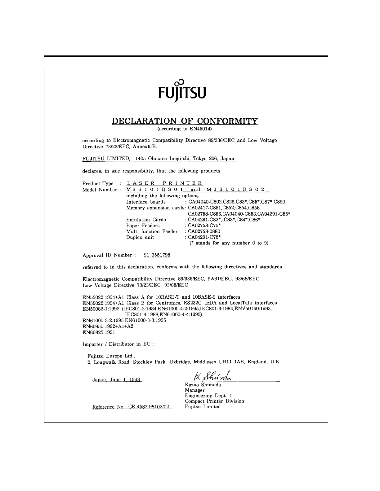
This product sold in Europe conforms to the standards in accordance
with EC Directives. The copy of “Declaration of Conformity” is
attached in the next page.
CE Declaration
Page 5
FM-4 User’s Manual
Page 6

User’s Manual FM-5
International Business Machines
Corporation: IBM, IBM PC/AT, IBM
PS/2, PC-DOS, Proprinter 4202
Microsoft Corporation: Microsoft, MSDOS, Windows
Lexmark International Inc.: MarkVision
Miles, Inc.: Intellifont
Novell, Inc.: Netware
Pipeline Associates, Inc.: PowerPage
Seiko Epson Corporation: EX-800
Xerox Corporation: 4024, Ethernet,
Xerox
FUJITSU is a registered trademark of
FUJITSU LIMITED. The following
companies own the other trademarks
used in this manual:
Adobe Systems, Inc.: PostScript
Apple Computer, Inc.: AppleTalk,
LocalTalk, Macintosh, TrueType
AT&T: UNIX
Centronics Data Computer
Corporation: Centronics
Hewlett-Packard Corporation: HewlettPackard, LaserJet, LaserJet 5, PCL
The contents of this manual may be revised without prior notice and
without obligation to incorporate changes and improvements into units
already shipped.
FUJITSU has made every effort to ensure that the information included
here is complete and accurate at the time of publication. The company
assumes no liability for errors and omissions.
Copyright © 1999 FUJITSU LIMITED
Printed in Japan. All rights reserved. No part of this manual may be
reproduced or translated, stored in a database or retrieval system, or
transmitted, in any form or by any means, electronic, mechanical,
photocopying, recording, or otherwise, without the prior written
permission of FUJITSU LIMITED.
C145-Exxx-01EN, April 1999
Trademark Acknowledgment
Page 7

FM-6 User’s Manual
Precautions
Read this section and remember these instructions to ensure your
safety and your printer’s correct performance. Follow the cautions
and notices labeled on the printer or marked with icons in the
manual. Save this manual for future reference.
• Use only the power cord furnished with the printer and a properly grounded
outlet. Do not use an extension power cord.
• Confirm that the rated voltage of your printer matches the voltage of your
power outlet. The maximum wattage of the printer is 600 watts.
• Turn off the printer and disconnect the power cord before beginning
maintenance operations.
• Disconnect the power cord from the outlet whenever you are not using the
printer for an extended period of time.
• Disconnect the power cord from the outlet whenever thunder storms are
nearby. Leaving the power cord connected may allow damage to the printer
or other property.
• Do not put the printer in direct sunlight, near a heater, or near water. Leave
adequate space around the printer.
• Do not touch any connector contacts. This could cause electrostatic damage
to the printer.
• Do not touch the heat roller and motors if you have been printing recently.
These parts may be hot.
• Do not touch or scratch the green drum surface, and do not expose it to light
for more than three minutes.
• Use only a shielded interface cable of 3 meters (10 feet) or less for the parallel
interface, 15 meters (50 feet) or less for the serial interface, 100 meters (328
feet) or less for Ethernet interface 10BASE-T/100BASE-TX connection, and
185 meters (607 feet) or less for the Ethernet interface 10BASE-2 connection.
• Be sure the printer is turned off before connecting the interface.
• Do not turn the printer off while it is printing.
• Do not disassemble or remove any components unless instructed in this
manual.
• Keep the print unit upright when removing or installing it.
• Do not use alcohol or other cleaning solutions on the drum surface or on any
interior parts of the printer.
• Clear paper jams quickly, especially when they occur in the heat roller unit.
• Do not drop small objects, such as paper clips, into the printer.
• Do not set page margins off the physically printable page area.
• Turn off the printer and disconnect the power cord immediately if an
abnormal condition occurs: for instance, if the printer smokes, prints
abnormally, becomes wet, or falls. Then consult your dealer.
Page 8

User’s Manual i
Contents
Preface ............................................................................................v
Manual and Software Set.................................................................vi
Operating Environments .................................................................vi
Conventions ...................................................................................vii
Control Panel..........................................................................viii
Changing Message Language.....................................................ix
Chapter 1 Getting Started ........................................................................... 1–1
Getting Acquainted ..................................................................... 1–1
Getting Ready ............................................................................. 1–4
Picking a Suitable Location................................................... 1–4
Unpacking and Checking Your Printer ................................. 1–5
Setting Up................................................................................... 1–7
Preparing the Print Unit ....................................................... 1–7
Loading Paper and Installing the Paper Tray....................... 1–10
Using the Multi-function Feeder......................................... 1–13
Connecting the Power Cord ............................................... 1–14
Connecting the Printer to Your Computer ................................ 1–15
About Interfacing................................................................ 1–15
Connecting to the Parallel Port ........................................... 1–16
Connecting to the Serial Port (12MX only) ........................ 1–16
Connecting the Serial Interface Cable........................... 1–17
Verifying Serial Parameter Settings............................... 1–17
Printing a Test Page Offline................................................ 1–19
Selecting an Emulation.............................................................. 1–20
Installing a Printer Driver.......................................................... 1–21
Get to Know Your Printer Driver ....................................... 1–22
Printer Drivers Supplied by the CD-ROM ......................... 1–23
Printer Drivers Supplied by the Floppy Disk....................... 1–23
Page 9

ii User’s Manual
Installing Other Software........................................................... 1–24
PPMENU .................................................................... 1–24
Lexmark’s MarkVision™............................................. 1–25
Printing Your First Document................................................... 1–26
Adjusting Print Density ...................................................... 1–27
If Something Goes Wrong .................................................. 1–28
Where To Go From Here.......................................................... 1–29
Chapter 2 Printing and Paper Handling ...................................................... 2–1
Control Panel Tutorial ................................................................ 2–1
The Control Panel ................................................................ 2–1
Indicators ....................................................................... 2–2
Message Display (LCD) ................................................. 2–3
Buttons........................................................................... 2–3
Control Panel Functions.............................................................. 2–5
Changing Message Language................................................. 2–5
Printing Data Remaining in the Buffer ................................. 2–5
Clearing an Error Condition to Continue Printing ............... 2–5
Clearing the Buffer and Reinitializing the Printer.................. 2–6
Clearing EEPROM............................................................... 2–6
Selecting the Self Test Menu................................................. 2–8
Selecting the Font Print Menu............................................ 2–10
Selecting Paper Tray, MFF, or Manual Feeder.................... 2–12
Setting MFF Paper Size....................................................... 2–15
Selecting the Thickness Control Menu ............................... 2–16
Selecting Menu Option and Resetting Menu ...................... 2–20
Menu Functions ........................................................................ 2–20
Menu Structure and How to Use Control Panel Buttons.... 2–20
Submenus, Items, and Options........................................... 2–21
Menu Items............................................................................... 2–25
Handling Paper ......................................................................... 2–34
Paper Types and Sizes ......................................................... 2–34
Adjusting for Paper Thickness ...................................... 2–37
General Tips................................................................. 2–38
Preprinted Sheets.......................................................... 2–39
Transparencies.............................................................. 2–39
Envelopes ..................................................................... 2–40
Labels ........................................................................... 2–41
Changing the Paper Tray Size ............................................. 2–41
Contents
Page 10

User’s Manual iii
Using the Multi-function Feeder or Manual Feeder ............ 2–44
Multi-function Feeder .................................................. 2–44
Manual Feeder.............................................................. 2–47
Setting Up the Rear Stacker ................................................ 2–47
Printing on Custom-Sized Paper......................................... 2–48
Page Orientation................................................................. 2–49
Chapter 3 Enhancing and Customizing the Printer ..................................... 3–1
Adding RAM............................................................................... 3–1
Installing an Alternate Emulation ................................................ 3–5
Installing an Interface Expansion Board....................................... 3–6
Installing an Interface Board ................................................. 3–6
Connecting to the LocalTalk Port......................................... 3–7
Connecting the LocalTalk Interface Cable...................... 3–7
Selecting the LocalTalk Interface.................................... 3–8
LocalTalk Specifications ................................................. 3–8
Connecting to the Ethernet Port........................................... 3–8
Connecting the Ethernet Interface Cable........................ 3–8
Selecting the Ethernet Interface ...................................... 3–9
Ethernet Specifications ................................................... 3–9
Adding Paper Sources................................................................ 3–10
Paper Feeder ....................................................................... 3–10
Changing the Paper Tray Size....................................... 3–11
Adding Duplex Unit.................................................................. 3–13
Chapter 4 Maintenance .............................................................................. 4–1
Preventive Maintenance............................................................... 4–1
Periodic Routine Maintenance .................................................... 4–2
Replacing the Developer Unit and Drum Unit ..................... 4–2
Developer Unit............................................................... 4–3
Drum Unit..................................................................... 4–5
Replacement................................................................... 4–6
Clearing a Service-life Counter ..................................... 4–10
Cleaning the Paper Path...................................................... 4–14
Repacking the Printer................................................................ 4–15
Contents
Page 11

iv User’s Manual
Contents
Chapter 5 Solving Problems ....................................................................... 5–1
Clearing Paper Jams .................................................................... 5–2
Recovery from Paper Jams .................................................... 5–3
Jam 0: from a Paper Tray to the Print Unit......................................
5–3
Jam 1: under the Print Unit or in the Fuser Unit.............................
5–5
Jam 2: under the Print Unit near the Paper Tray .............................
5–6
Jam 3: in the Fuser Unit ..................................................................
5–7
Jam 4 (12MX only): from the Eject Unit to the Duplex Unit ..........
5–9
Jam 5 (12MX only): from the Duplex Unit to the Print Unit........
5–11
Jam 6: at the Feed Roller of the Optional Paper Tray ....................
5–12
Cleaning the Paper Path...................................................... 5–13
Operational Problems................................................................ 5–16
Print Quality Problems.............................................................. 5–17
Error Indications ....................................................................... 5–20
Action-required Status Indications............................................. 5–23
Printer Status Indications .......................................................... 5–24
Warning Messages..................................................................... 5–25
Appendix A Font Samples ..............................................................................A–1
PCL Mode .................................................................................. A–1
FPS Mode ...................................................................................A–3
Appendix B Supplies and Accessories.......................................................... B–1
Supplies....................................................................................... B–1
Accessories...................................................................................B–1
Appendix C Specifications ............................................................................C–1
Appendix D Command Sets
(in IBM Proprinter 4202/EPSON EX-800 Emulation)............. D–1
Glossary................................................................................... GL–1
Index......................................................................................... IN–1
Fujitsu Offices.........................................................Inside back cover
Page 12

User’s Manual v
Preface
Thank you for purchasing the Fujitsu PrintPartner 12M/12MX Page
Printer. The PrintPartner 12M is a 12-ppm, 600-dpi, laser printer
with a Centronics parallel interface (type B connector). The
PrintPartner 12MX is a 12-ppm, 600-dpi or 6-ppm, 1200-dpi, laser
printer with two interfaces consisting of Centronics parallel (type B
connector) and RS-232C serial (DB9 connector). Both models are
compatible with the HP LaserJet 5 printers, IBM Proprinters 4202,
and EPSON EX-800 printers. The PrintPartner 12MX is also
compatible with PostScript level 2 printers by using the PowerPage®
Level 2 interpreter.
Options available for both 12M and 12MX are:
• 4-, 8-, 16-, and 32-megabyte memory expansion cards
• Interface expansion boards: Centronics parallel (type B connector),
LocalTalk, Ethernet C, D, F, or GXL, IrDA, and USB
• FLASH ROM card: 4-megabytes, for PCL5e or PCL-XL mode in
PCL emulation
• Barcode card: Barcodes and OCR fonts
• 500-sheet paper feeder: Base mechanism plus 500-sheet paper tray
(tray 2; A4, A5, JIS B5, letter, legal, and executive sizes)
Options available for 12M only are:
• FPS card: PostScript level 2 emulation
Options available for 12MX only are:
• Duplex unit: Two-sided printing mechanism
Page 13
vi User’s Manual
The PrintPartner 12M/12MX has a single user’s manual. This user’s
manual provides a summary of everything for from non-technical
users unfamiliar with page printers to highly experienced technical
users.
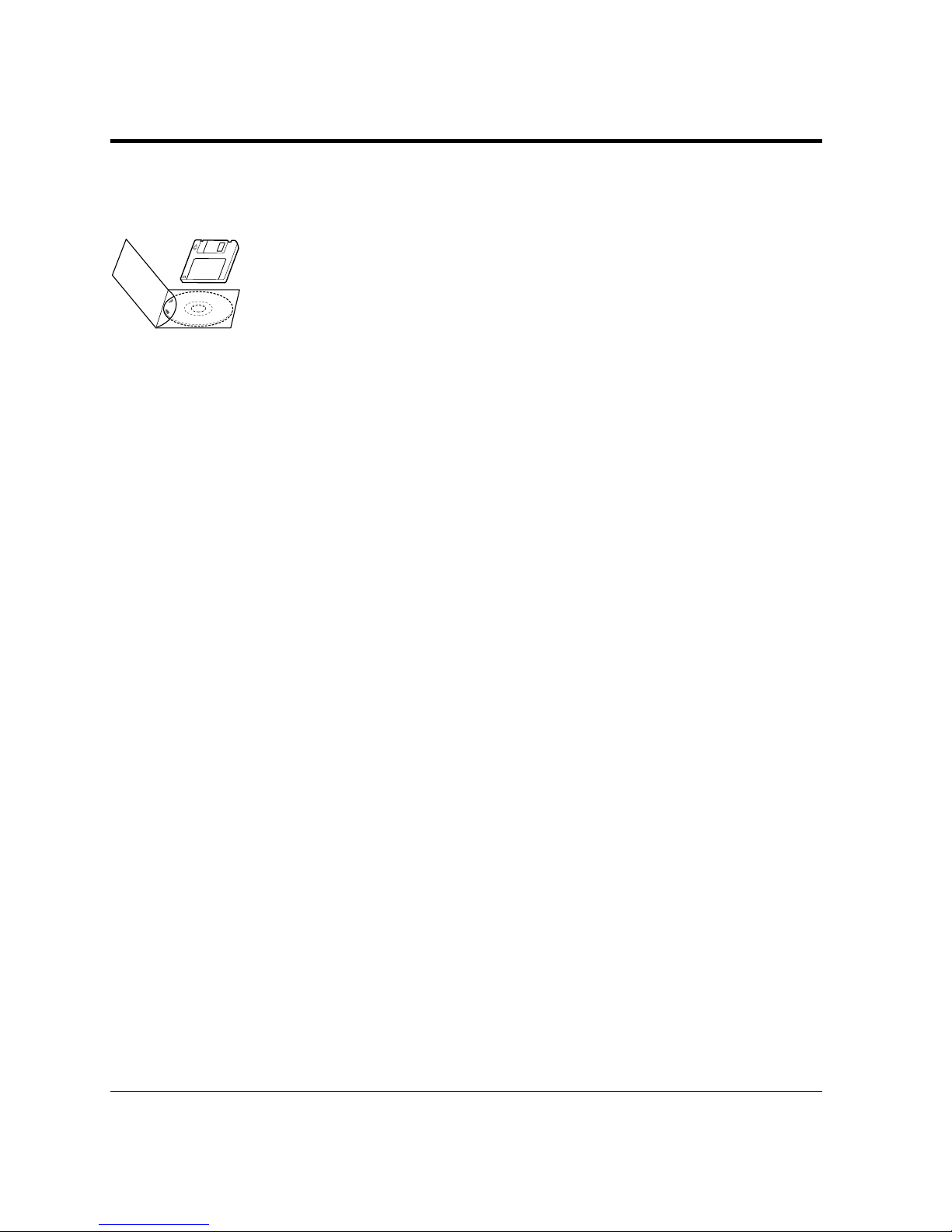
The PrintPartner 12M/12MX comes with a software set (a CDROM and a floppy disk) to supply you with the following items of
printer control software.
• Printer Drivers for Windows 95/98, NT 3.51, and NT 4.0, which
provide the computer’s operating system with the programs that
control this printer.
• MarkVision™ by Lexmark for Windows 95/98/NT 4.0, printer
management utility programs, which allow you to easily understand
the printer (status, statistics, or features) and displays the printer
control panel on your computer display to remotely operate the
printer.
• Network Printer Utility for Windows 3.x, which allows you to
remotely change or confirm settings of an Ethernet interface board
of the printer or locally check the printer.
• PPMENU for MS-DOS, printer remote setup utility program,
which allows you to easily customize and program your printer to
your computer and software environments, using your computer
keyboard and display
The CD-ROM contains all items of the software but the floppy disk
contains printer drivers for Windows 3.x only.
To run a Printer Driver, you need an IBM PC/AT or PS/2 computer
or compatible running MS-Windows 3.x, MS-Windows 95/98, MSWindows NT 3.51, or MS-Windows NT 4.0.
To run MarkVision™, you need an IBM PC/AT or PS/2 computer
or compatible running MS-Windows 95/98 or MS-Windows NT
4.0, with at least 9MB of memory available on a hard disk, a CD-
ROM drive or a 3.5" double-sided high density (2HD) floppy disk
drive, and a VGA (640 × 480 dots) or higher resolution display.
Operating
Environments
Manual and
Software Set
Page 14
User’s Manual vii
☞
✍
Conventions
To run the Network Printer Utility, you need an IBM PC/AT or PS/
2 computer or compatible running MS-Windows 3.1/3.11, with at
least 5MB of memory available on a hard disk, a CD-ROM drive or
a 3.5" double-sided high density (2HD) floppy disk drive, and a
VGA (640 × 480 dots) or higher resolution display.
To run PPMENU, you need an IBM PC/AT or PS/2 computer or
compatible running MS-DOS, with at least 1MB of memory
available on a hard disk, a CD-ROM drive or a 3.5" double-sided
high density (2HD) floppy disk drive, and a VGA (640 × 480 dots)
display. You must also be using PC-DOS version 5.02, MS-DOS
version 3.3, or higher version.
Icons draw your attention to advisory messages, as illustrated below.
A line precedes and follows the message to show where the message
begins and ends.
Warning:
Ignoring this information could result in personal injury.
Caution:
Ignoring this information could result in loss of data or harm to your
equipment.
Important:
These notes contain remarks, tips, and other useful supplementary
information.
!
Page 15
viii User’s Manual
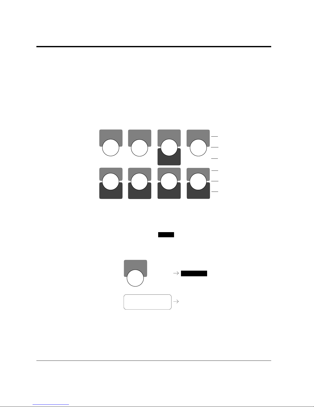
Control Panel
The printer’s control panel incorporates two rows of buttons, with
each button having one or two labels (see below). The physical
button is beneath the rectangular section of no-labeled space. The
top label represents the basic function, which is activated by a touch
of the button. The bottom label represents the second function,
which is activated when you release the button after holding it down
more than five seconds.
MFF
PAPER SIZE
PRINT
FONT
SELF
TEST
RESET
CONT.
ENTER
–
+
MENUREADY
FORM
FEED
RESET
MENU
SELECT
Basic functions
Second functions
Physical buttons
Basic functions
Second functions
Physical buttons
The control panel has a character display of 16 columns × 2 lines.
In text, the names of the control panel buttons appear as all capital
letters inside a box like
READY
and control panel display messages
appear in a fixed-spacing font like
READY. Button names or messages
occupying two lines are expressed in a single line shown below.
Buttons:
Display
messages:
<CLEAR WARNING> DEVELOPER UNIT*
<CLEAR WARNING>
DEVELOPER UNIT*
FORM
FEED
FORM FEED
The asterisk in the display column indicates that the displayed
option is currently selected in the selected menu.
Page 16

User’s Manual ix
Changing Message Language (
MENU
)
You can select a language used for control panel messages. Selectable
languages are English, French, German, Italian, Spanish, and
Swedish.
To select a language, follow these steps:
1. Turning the printer on while pressing
MENU
.
The message
C.P.LANGUAGE ENGLISH appears after printer
initialization.
2. Press the
+
or – button until the desired language appears.
Press the
ENTER
button.
The asterisk appears after the language, indicating the language is
selected.
3. Save the selection.
Pressing the
READY
button saves the new setting and returns the
printer to the ready state. The printer will display the selected
language for messages.
Page 17

x User’s Manual
Page 18

User’s Manual 1-1
GETTING
STARTED
1
CHAPTER
Getting Started
This chapter provides complete setup instructions in the following
sections:
• Getting Acquainted. Learning the printer’s main parts and its paper
paths.
• Getting Ready. Choosing a suitable location and unpacking the
printer.
• Setting Up. Assembling the printer.
• Connecting the Printer. Selecting an interface and connecting to the
computer.
• Installing a Printer Driver and other software.
• Printing Your First Document.
• Where to Go from Here.
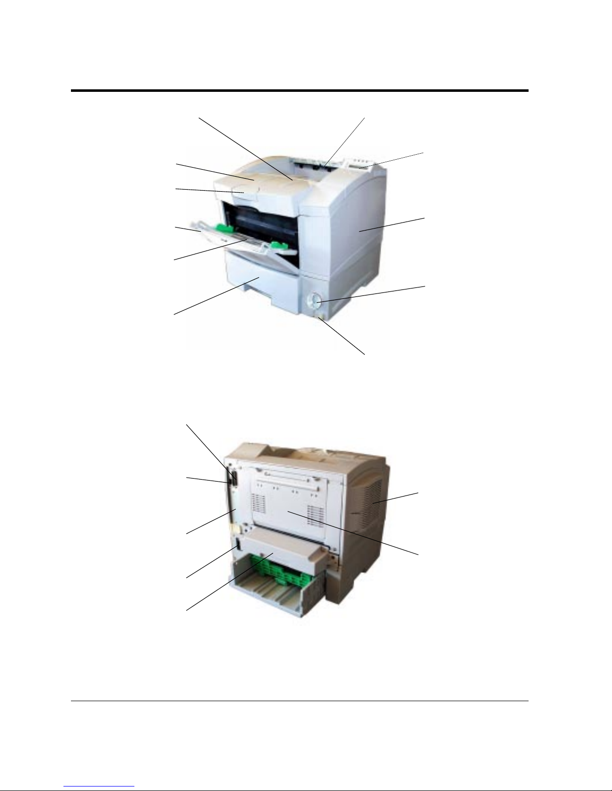
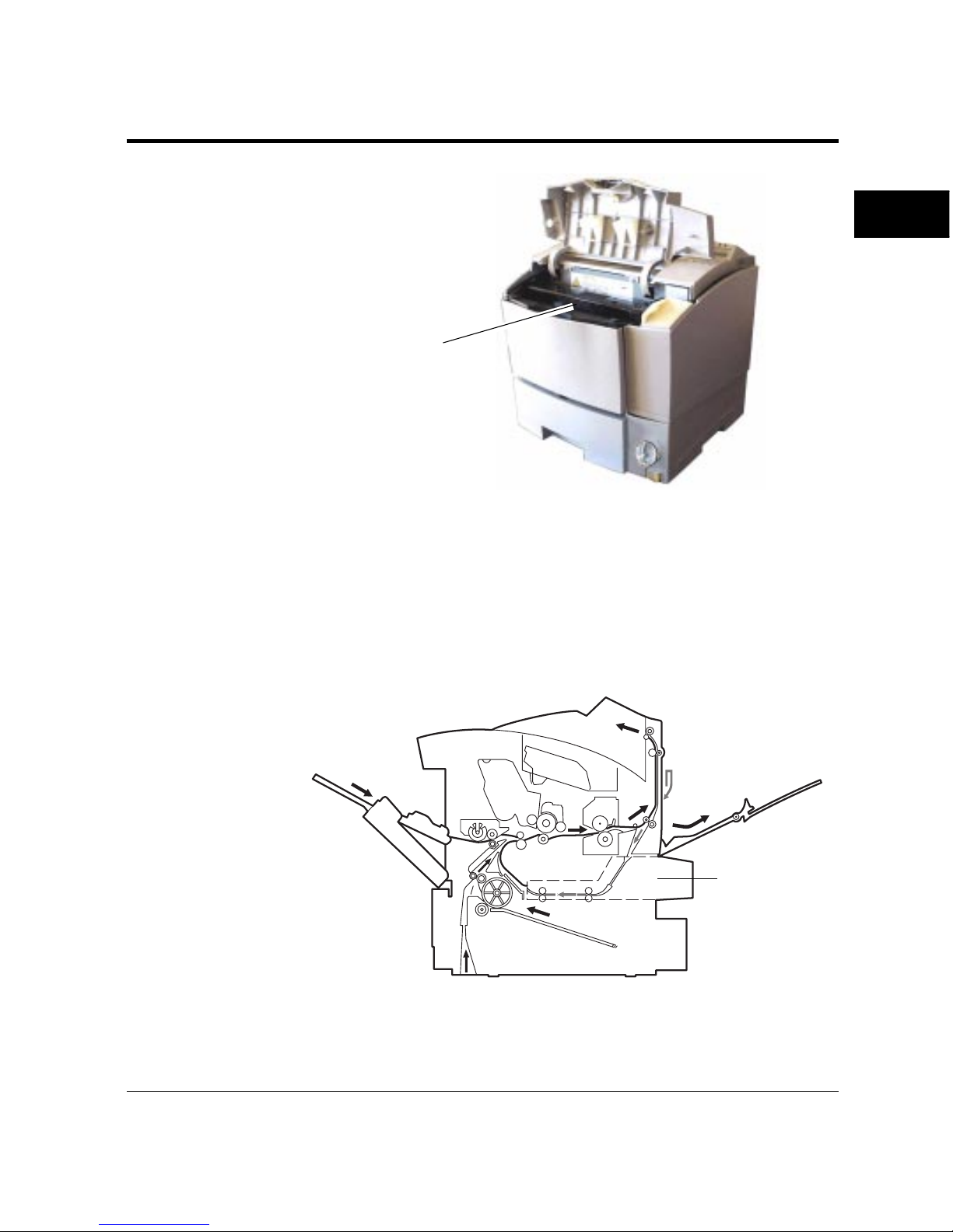
The photos and illustrations on the following pages identify the main
parts of the printer and two routes of paper feeding. These parts are
referred to throughout the manual, so take some time to become
familiar with them.
Getting
Acquainted
Page 19
1-2 User’s Manual
Figure 1–1 Front and right side view
Figure 1–2 Rear and left side view
Getting Acquainted
Power cord connector
Power switch
Top cover
(Face-down stacker)
Duplex unit
(option for PP12MX)
Centronics parallel
interface connector
(IEEE1284 type-B)
Interface board slot cover
Fan (outflow)
Control panel
Multi-function
feeder (MFF)
Paper tray
Paper stopper
Upper door
Side cover (Font/
emulation card slot
and RAM card slots
inside)
Paper size dial
Rear stacker
(Face-up stacker
when opened)
Front door
RS-232C serial interface
connector (D-SUB 9-pin)
(standard for PP12MX)
Stacker-full sensor
Page 20
User’s Manual 1-3
GETTING
STARTED
Getting Acquainted
From optional paper tray
Figure 1–3 Interior view
The path from the paper tray to the top cover is for ordinary paper.
The straight path from the multi-function feeder to the rear stacker
is for thick paper, transparencies, and envelopes.
Figure 1–4 Paper paths
Paper tray
Top cover
(main stacker)
Rear
stacker
Multi-function
feeder (MFF)
Print unit (developer unit
and drum unit)
Duplex unit
(option for 12MX
only)
Page 21
1-4 User’s Manual
Getting Ready
Caution:
The duplex unit restricts automatic double-sided printing as follows:
• Paper size must be longer than 210 mm.
• Paper thickness must be 60 g/cm
2
to 105 g/cm2.
• The rear stacker cannot be used.
If you do not observe these restrictions, paper jams may occur.
This section will help you:
• Choose a suitable location for the printer
• Inventory the parts of the printer as you unpack it
Picking a Suitable Location
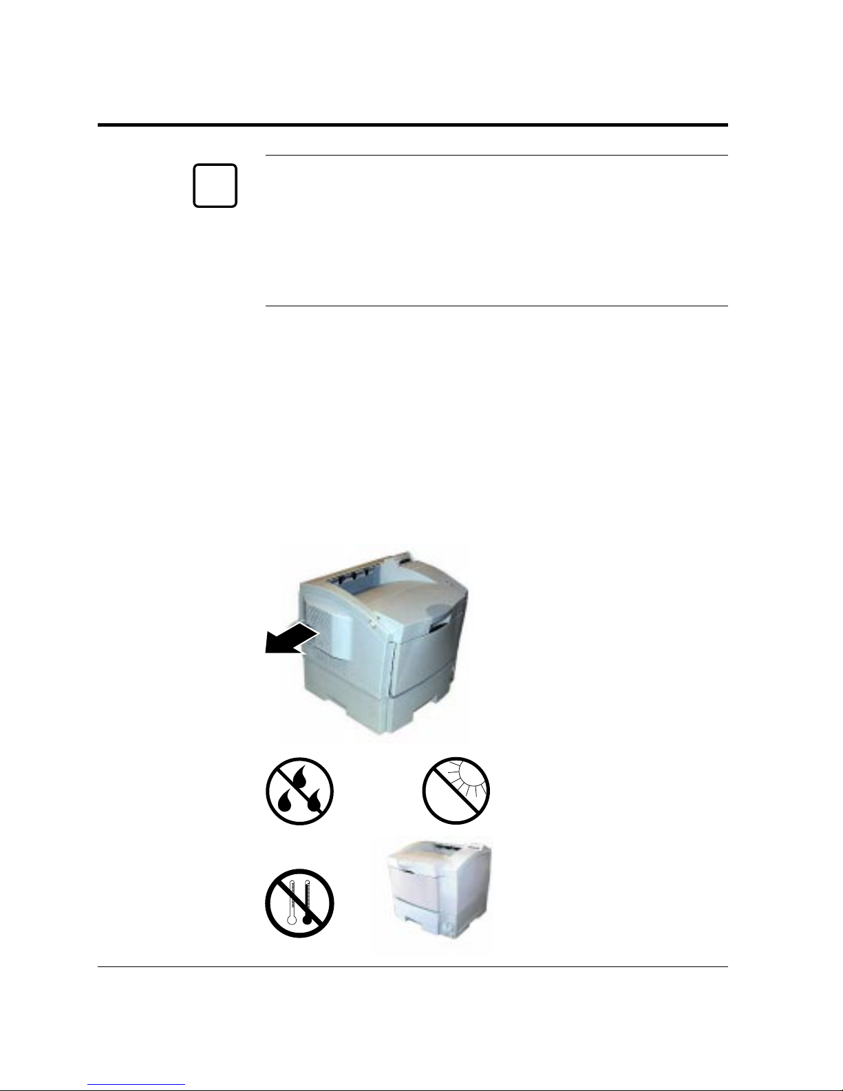
The first step is to pick a suitable location for your printer. For peak
performance and usability, follow these guidelines:
• Place the printer on a
sturdy, level surface.
• Choose a room that is well
ventilated and free of
excessive dust. Leave space
around the printer
especially on the left side for
proper ventilation.
• To avoid exposing the
printer to extremes of
temperature, do not put the
printer in direct sunlight or
near a heater. Ideal room
temperature is from 10°C
to 32°C (50°F to 90°F).
Humidity should be
between 20% and 80% RH
(no condensation).
Getting Ready
below
+10
°C
above
+32
°C
☞
Page 22
User’s Manual 1-5
GETTING
STARTED
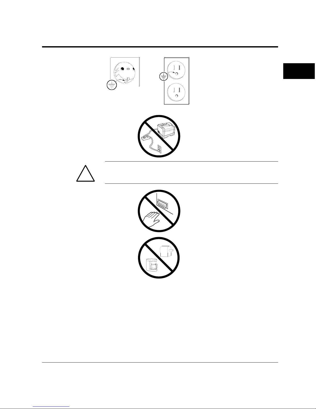
• Use a grounded AC power
outlet. Do not use a threepronged adapter in an
ungrounded outlet.
• Use only the power cord
furnished with the printer.
Do not use an extension
cord.
Warning:
For your safety from an electric shock, observe the above prohibition.
• Do not touch any
connector contacts to avoid
possible electrostatic
damage to the printer.
• Do not use a circuit shared
with equipment that causes
electrical noise, such as
motors.
• Do not use a circuit shared
with equipment that uses a
lot of power, such as a
copier or a coffee maker.
Unpacking and Checking Your Printer
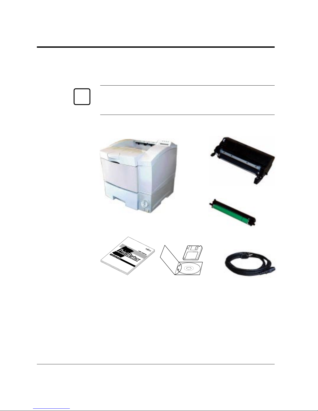
As you unpack the printer, check each item carefully for damage. If
you find damage, notify your dealer. Check also that you have
received all the items shown below.
Getting Ready
!
Page 23
1-6 User’s Manual
This printer comes with everything you need except an interface
cable. If you do not yet have a cable, you must purchase one before
you can connect the printer to your computer.
Important:
Save the original carton and packing materials in case you need to
store or transport your printer.
• An interface cable is not a standard accessory. Please purchase
an appropriate cable according to the interface you intend to
use.
• The power cord may differ slightly from this figure depending
on the country where you purchased the printer.
• The software set consists of:
- CD-ROM labeled PrintPartner Software
- Floppy disk labeled Printer Drivers for Windows 3.x.
Figure 1-5 Printer inventory
Drum unit
Printer
Getting Ready
Developer unit
Power cord
Quick installation
guide
Software set
(printer drivers and
other software)
✍
Page 24
User’s Manual 1-7
GETTING
STARTED
This section describes how to assemble the printer and connect the
power cord after choosing a suitable location for the printer and
checking that you received all the parts.
Preparing the Print Unit
The print unit is an assembly made up the developer unit and the
drum unit. You must assemble these two units into the print unit. Be
sure to remove the two protective materials from the developer unit
and drum unit. This operation must be done before connecting the
power cord.
Caution:
Be careful with the print unit’s drum (the green surface). The drum
is easily damaged by contamination or by exposure to light for more
than three minutes. Follow these guidelines:
• Never open the shutter under the drum unit before until you are
ready to install the print unit.
• Never touch or scratch the drum surface.
• When the print unit is not in the printer, close the shutter of the
drum unit and store the print unit in a dark place or cover it with a
clean sheet of paper.
• When the print unit is in the printer, keep the printer upper door
closed. If you must work inside the printer for more than three
minutes, remove the print unit and store it in a dark place.
•If you store the print unit out of the printer, it may be
contaminated by dust. This may cause a smudge on the page.
When storing the print unit out of the printer, wrap it with paper
or something.
To install the print unit, follow these steps:
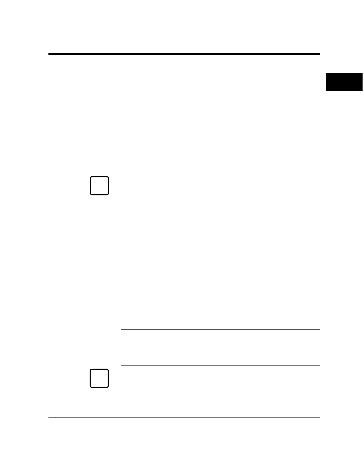
1. Remove the developer unit and the drum unit from the package.
Caution:
Never open the shutter of the drum unit to avoid scratching the
green surface of the drum.
Setting Up
Setting Up
☞
☞
Page 25

1-8 User’s Manual
Setting Up
2. Shake the developer unit
by rocking it from side to
side several times.
Place the developer unit on
a level, steady place.
3. Remove the plastic seal
from the developer unit.
Gently pull off the seal
being carefully not to spill
toner. Handle to seal
carefully to avoid staining
your hands or clothes.
4. Remove the drum
protecting sheet from the
drum unit.
5. Mount the drum unit on
the developer unit.
Holding the drum unit with
its shutter facing outside,
insert one end of the drum
unit shaft into the bearing
hole of the developer unit.
Page 26
User’s Manual 1-9
GETTING
STARTED
Setting Up
Put the other end of the
shaft on the other bearing
and close the ark-shaped
green lever to secure the
shaft.
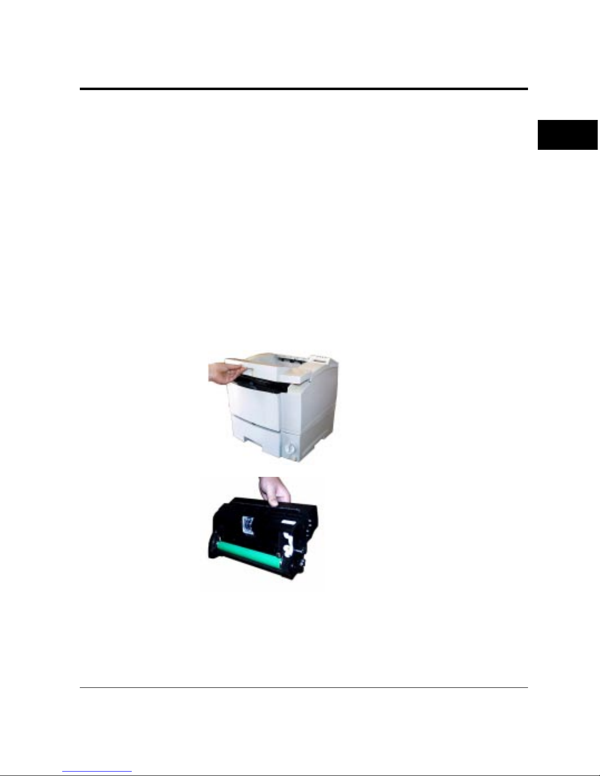
6. Open the shutter of the
drum. Holding the top
center of the print unit,
push up backwards the
green-labeled handle of the
shutter under the print unit
and fix the shutter on the
hook.
7. Open the upper door. lift
th center portion under the
stopper of the upper door to
open it.
8. Orient the print unit.
Hold the top center of the
print unit with the green
drum facing you and adjust
the ends of the drum shaft
to the grooves on the sides
of the printer.
Page 27
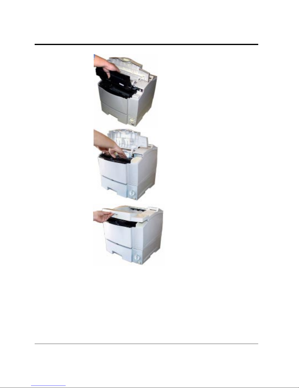
1-10 User’s Manual
9. Install the print unit.
Slide the print unit at a 45
degree angle along the
grooves and towards the
back of the printer.
10.Seat the print unit in
place. Press down gently on
the top left and right
portions of the print unit
until it clicks into place.
11.Close the printer’s upper
door. Press down firmly on
the front portion of the
upper door and make sure
the upper door is locked
completely.
Setting Up
Page 28
User’s Manual 1-11
GETTING
STARTED
Setting Up
Loading Paper and Installing the Paper Tray
This printer has a single paper tray that is preset for letter size (8.5 x
11.0 inches) paper for U.S. customers and to A4 size (210 x 297
mm) paper for European customers. (You can adjust the paper tray
to a different size paper. See Chapter 2. You can purchase an
optional paper tray. See Chapter 3 and Appendix B.) You should
load about 50 sheets of copier paper to test the printer.
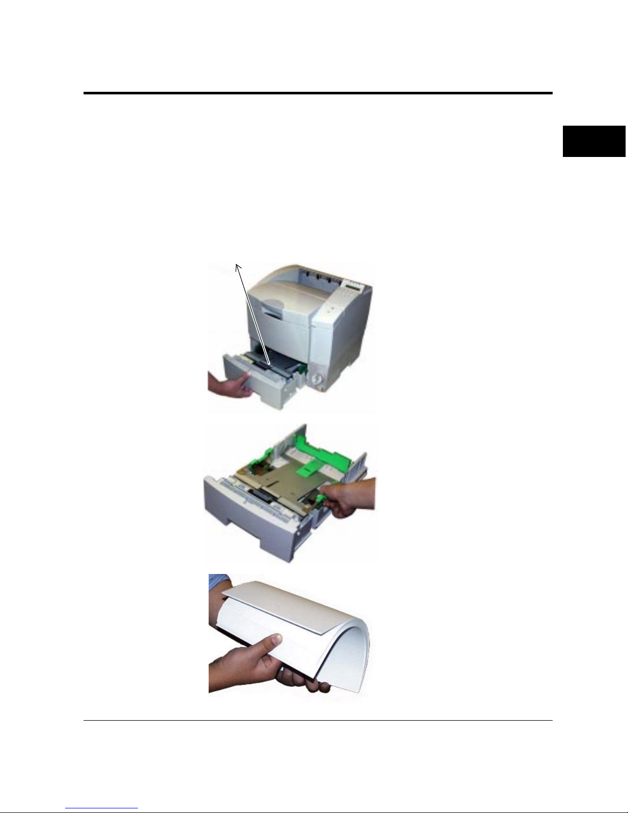
1. Pull the paper tray out of
the printer.
2. Prepare the paper tray.
Remove restraint card board
(1) and tapes securing the
rear paper guide.
3. Widen the side guides.
While holding right sideguide together with its lock
plate, push both guides
outwards.
4. Prepare a paper stack.
Prepare paper of the size
indicated by the paper size
dial (actually the paper size
scale where the rear guide of
the paper tray is set). Fan
the paper stack both ways to
prevent sheets from sticking
together.
(1)
Page 29
1-12 User’s Manual
Important:
Be sure to set the paper size dial correctly according to the loaded
paper. Improper setting may cause an error during printing.
Caution:
Put the paper stack in the paper tray with the printing side faced down.
If paper is curled, remove the curl.
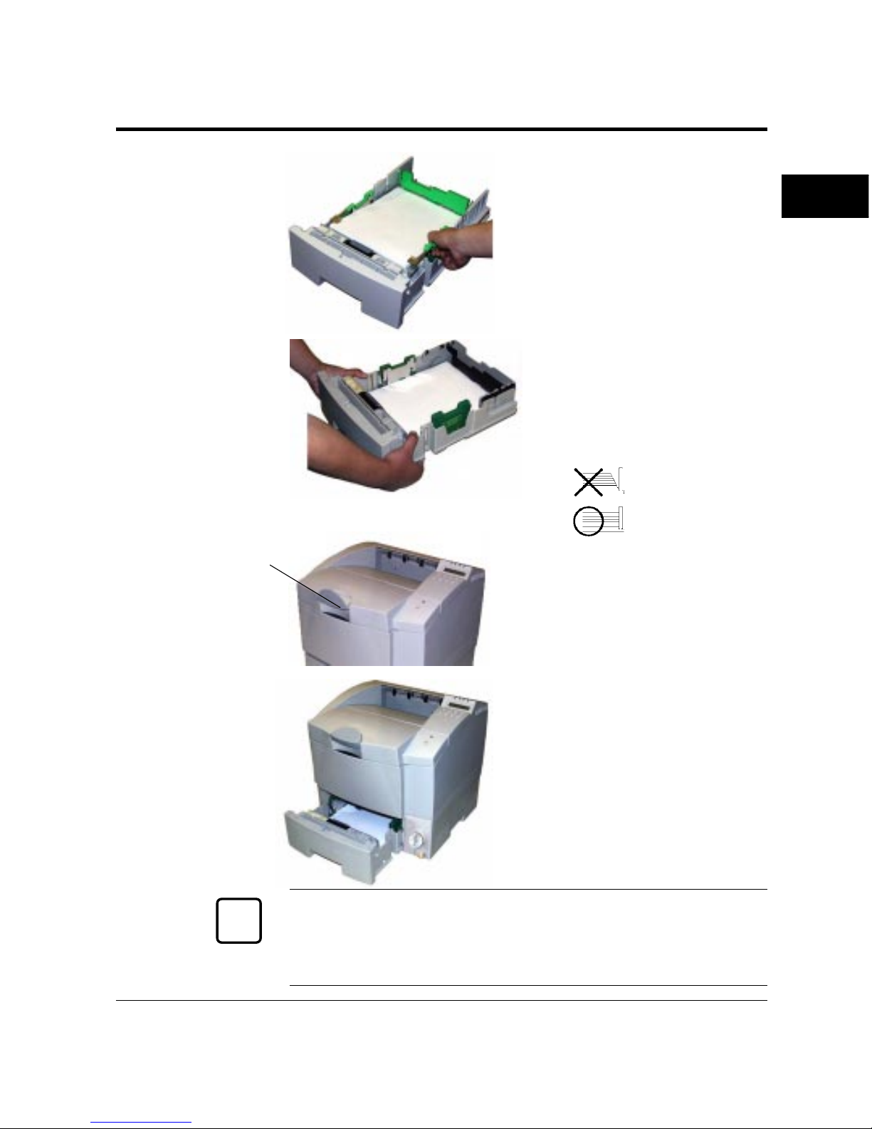
5. Load the paper. Place the
rear portion of the paper
stack on the tray and slide it
towards the rear of the tray
so that the front portion of
the stack is placed in
position at the front portion
of the tray.
Make sure the stack does
not exceed the limit marks
on either side guide.
6. Place the paper stack
under the paper holders.
Caution:
When additional sheets of paper are supplied to the tray which is not
empty, it may cause paper mispick, double-feed, skew at the
boundary between old paper and new paper.
Setting Up
Limit marks
▼▼▼
☞☞
✍
Paper
holder
Page 30
User’s Manual 1-13
GETTING
STARTED
Setting Up
7. Adjust the side guides.
Push the lock plate of the
right side-guide inwards to
fit the side guides to the
width of paper snugly.
Align the rear edges of the
paper stack.
8. Arrange paper edges. Rock
the paper tray to gather the
edges of the stack together
to ensure correct
positioning of paper in the
tray.
9. Raise the paper stopper.
10.Install the paper tray.
Align the sides of the tray
with the guide grooves of
the tray slot and firmly slide
the tray all the way into the
slot.
Important:
Do not turn the paper size dial after you have loaded paper.
Changing the dial setting causes a paper mismatch error when
printing the paper.
✍
Paper
stopper
Bad placement
Good placement
Page 31
1-14 User’s Manual
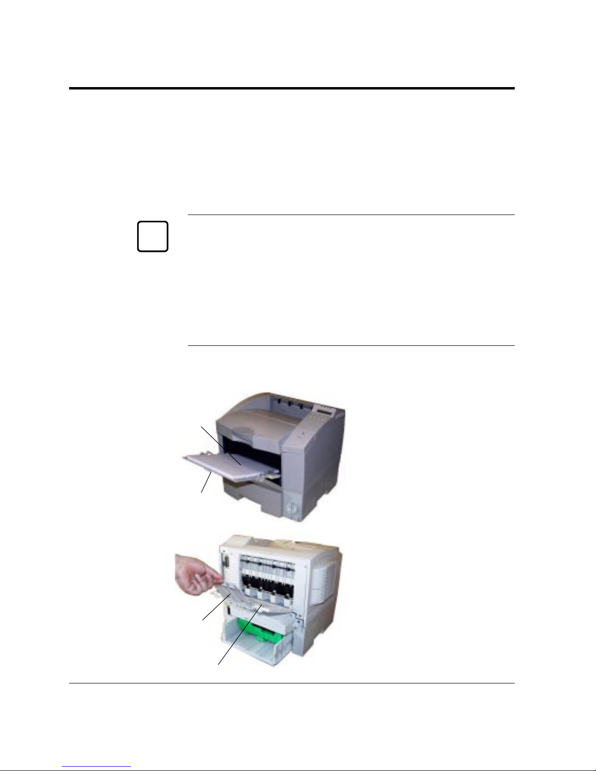
Using the Multi-function Feeder
The multi-function feeder (MFF) is built in this printer. It is useful
to print a lot of of thick paper, envelopes, or transparencies. It can
hold and deliver 100 sheets of 80 g/m
2
paper, 20 shetts of thick
paper, or 20 envelopes (this value may decrease depending on types
of envelopes).
Important:
When using paper, do not leave the paper in the multi-function
feeder for long time. It may cause waving of paper and dropouts in
printing.
Because the MFF does not have a mechanism that detects the
physical size of paper in use, you must inform the printer of the
paper size. Use the MFF paper size menu to select a paper size which
equals the size of paper loaded in the MFF. See Chapter 2.
To use the multi-function feeder, follow these steps. For details, see
Chapter 2.
1. Open the front cover.
2. Extend the paper support.
Pull the center top of the
paper support all the way.
3. Adjust the paper guides.
Slide the paper guides to fit
the width of the paper
snugly.
4. Load paper. Place the
paper stack on the MFF and
push it all the way until its
front portion is stopped.
5. Open the rear stacker. If
necessary, open the rear
stacker.
6. Extend the subguide.
Setting Up
✍
Rear stacker
Paper support
Subguide
MFF with
paper loaded
Page 32
User’s Manual 1-15
GETTING
STARTED
Setting Up
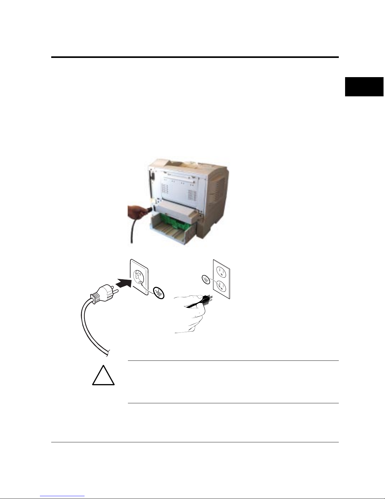
Connecting the Power Cord
This printer comes equipped with one of the two voltage ratings:
• 120 VAC (such as for the USA)
• 220 to 240 VAC (such as for Europe)
The manufacturer’s nameplate on the back of the printer indicates
this rating. Confirm that the rated voltage of your printer matches
the voltage of your power outlet.
1. Check that the printer is
turned off. The “O”marked side of the switch at
the right front of the printer
should be depressed.
2. Plug the female end of the
power cord into the
connector on the right
back of the printer.
3. Plug the male end into a
wall outlet.
Warning:
For your safety, use only a properly grounded outlet. To avoid
possible electromagnetic interference or power supply problems, do
not use an extension cord.
!
Page 33
1-16 User’s Manual
This section explains how to connect the printer to your computer
via the parallel or serial interface.
Important:
The following restrictions apply to interface cables:
• To comply with regulations for radio frequency emissions, use only
shielded cable for computer-to-printer communications.
• The length of the parallel interface cable must be 3 meters (10 feet)
or less.
• The length of the serial interface cable must be 15 meters (50 feet)
or less.
About Interfacing
Generally, you can connect the printer to your computer using a
standard parallel or serial interface. However, if your printer is used
as a network printer, use an optional LocalTalk or Ethernet interface.
An optional infrared interface is also provided.
• Parallel (Centronics) or serial (RS-232C, 12MX only)
Use a serial interface if the printer is not near the computer. Many
computers have both parallel and serial interface ports. Serial
communication can operate up to 15 meters (50 feet). Parallel
communication is normally limited to 3 meters (10 feet).
• LocalTalk (option)
Use the LocalTalk interface if the printer is connected to a
Macintosh network.
• Ethernet C, D, F, or GXL (option)
Use Ethernet C, D, F, or GXL if the printer is used in a NetWare
or TCP/IP corresponding.
• IrDA (option)
Use IrDA (infrared adapter) if the printer is used in an infrared
communications system.
• USB (option)
Use the universal serial bus if the printer is used in a Windows 98
system with a USB port.
Connecting the Printer to Your Computer
✍
Connecting the
Printer to Your
Computer
Page 34
User’s Manual 1-17
GETTING
STARTED
Whichever interface you use, the printer automatically detects the
interface that the computer is using.
For these options refer to Chapter 3.
Connecting to the Parallel Port
This printer does not come with a parallel interface cable. You can
use a Centronics cable with IEEE 1284 type B connector (sold
separately) at the printer side for this purpose. Your dealer can advise
you on the cable you require.
Caution:
Be sure the printer is turned off before connecting the interface.
Do not touch any connector contacts to avoid possible electrostatic
damage to the printer.
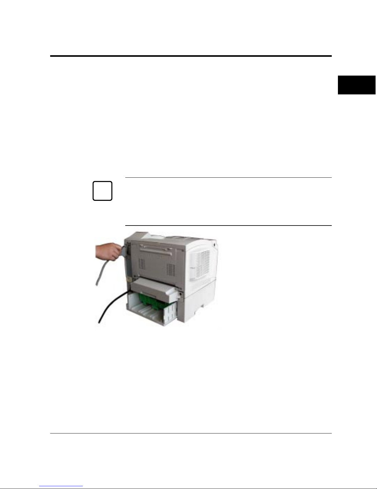
To make the connection,
plug the cable connector
into the parallel interface
port on the back of the
printer. Secure the
connector with the wire
clips. Plug the other
connector into your
computer’s parallel port.
Consult your computer
documentation if you need
help.
Connecting to the Serial Port (12MX only)
Connecting to the serial port involves the following tasks:
• Connect the interface cable to the printer and your computer.
• Print out the status report to check the serial parameter settings.
Connecting the Printer to Your Computer
☞
Page 35
1-18 User’s Manual
Connecting the Serial Interface Cable
To connect to the serial interface port, you need a cable correctly
wired for this printer and your computer. The cable must also have
the proper connectors. Your dealer or technical support person can
supply you with the proper cable.
The serial interface of this printer requires a null-modem cable with a
male D-SUB 9-pin connector at the printer side. Refer to your
computer documentation for the type of connector required by its
serial port.
Caution:
Be sure that the printer is turned off before connecting the interface
cable.
Do not touch any connector contacts to avoid possible electrostatic
damage to the printer.
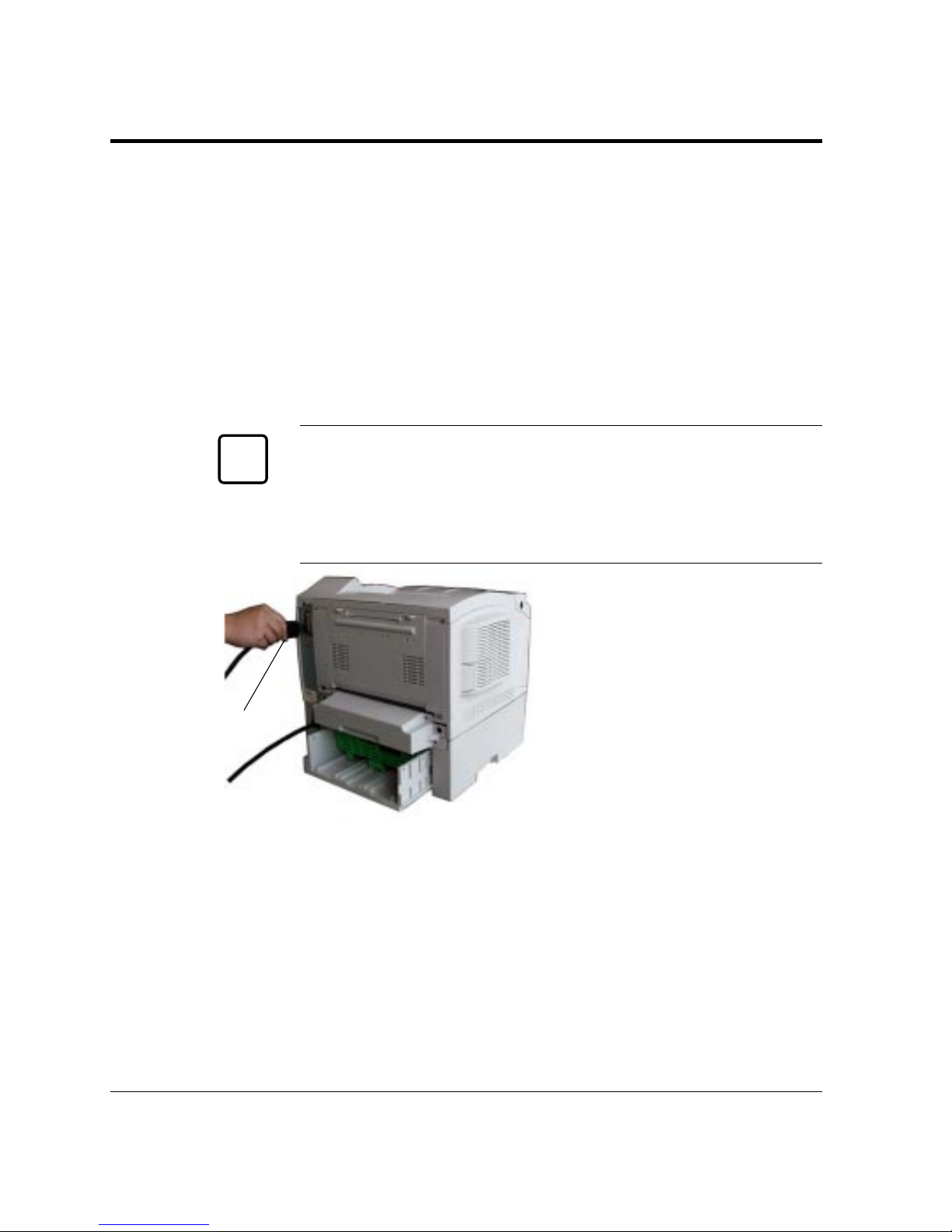
To make the connection,
plug the cable connector
into the serial interface port
at the back right of the
printer. Secure the
connector by tightening the
screws in the connector
hood. Plug the other
connector into your
computer’s serial port.
Consult your computer
documentation if you need
help.
Verifying Serial Parameter Settings
Next, you must make sure the serial parameter settings are the same
between the computer and the printer. Consult your computer and
software documentation to determine the settings your computer
uses. Then compare these to the printer’s settings in the following
table.
Connecting the Printer to Your Computer
☞
Secure
holding screws
Insert
connector
Page 36
User’s Manual 1-19
GETTING
STARTED
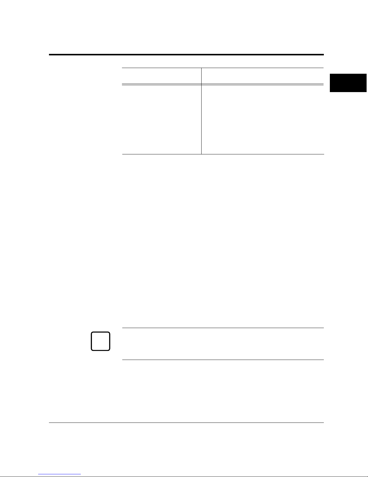
Item Parameter setting (printer side)
Baud rate 9600 (default)
Data bits 8 (fixed)
Stop bits 1 (fixed)
Parity None (fixed)
Pacing (protocol) DTR (default)
DTR polarity HI (default)
ROBUST (XON/XOFF) Off (default)
If the settings match, the installation is complete. If the interface
parameters of the printer and the computer do not match, the
message display indicates COMM.ERROR. The printer may not
respond at all or it may print wrong characters. Change the settings
in one of the two ways:
• Change options of the serial menu in setup mode.
• Set permanent defaults in your computer to match the printer’s
defaults.
On an IBM PC or compatible computer running MS-DOS, you can
set permanent defaults by placing the following commands in your
AUTOEXEC.BAT file:
MODE COM1:9600,N,8,1,P
MODE LPT1:=COM1:
Also make sure that the file MODE.COM is in your boot directory.
Then whenever you boot your computer, the computer will print
through the serial port using the printer’s settings.
Important:
For information on DOS files and commands, consult your DOS
manual or the manual supplied with your computer.
Note that you may also be able to specify serial parameters through
your software programs. Some software programs allow you to
specify the printer port and serial settings from within the program.
Consult the documentation supplied with the software.
✍
Connecting the Printer to Your Computer
Page 37
1-20 User’s Manual
POWER
ONLINE
DATA
ERROR
MFF
PAPER SIZEPAPER SIZE
PRINT
FONT
SELF
TEST
RESET
CONT.
ENTER
–
+
MENUREADY
FORM
FEED
RESET
MENU
SELECT
Printing a Test Page Offline
Printing a Test Page Offline
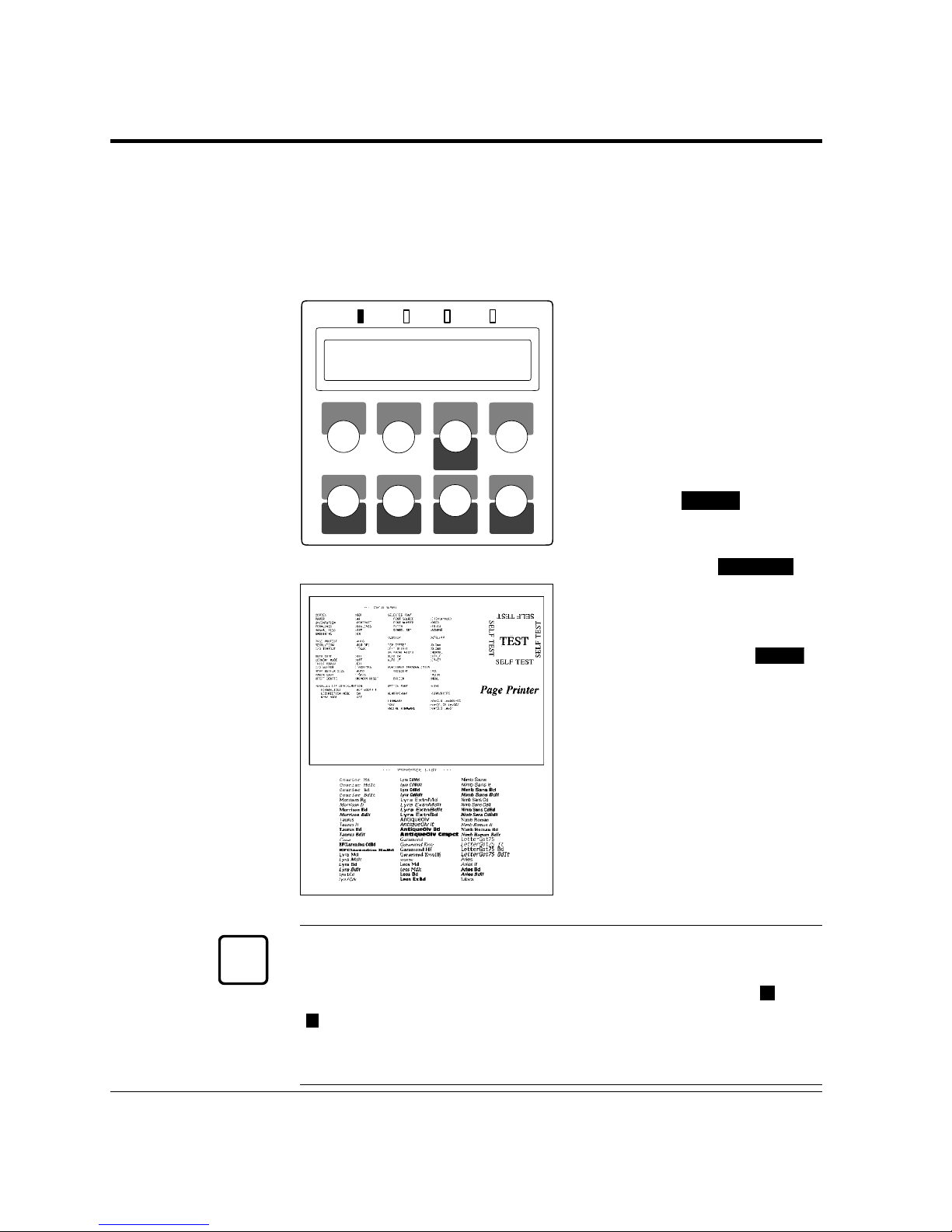
The printer has a status report function which prints a page
summarizing printer option settings and showing samples of resident
fonts. Use this function to check the printer performance offline.
1. Turn the printer on. The
printer initializes the
mechanism and then enters
the ready state. The message
display indicates
<<<INITIALIZE>>>,
WARMING UP, then READY.
2. Print a test page offline.
Press the
READY
button to
put the printer offline (the
ONLINE indicator turns
off). Press the
SELF TEST
button for more than five
seconds. The message
display indicates
PCL PAGE
CONFIG. Press the
ENTER
button to start printing.
The message display
indicates
SELF TEST and
the DATA indicator flashes.
A status report page is
printed.
Check that the printing is
successful.
Important:
You can select PP PAGE CONFIG or EX PAGE CONFIG for both
models or FPS PAGE CONFIG for PP12MX by pressing the
+
or
–
button while the message display indicates PCL PAGE CONFIG.
PP: IBM Proprinter 4202 emulation
EX: EPSON EX-800 emulation
READY
✍
Page 38
User’s Manual 1-21
GETTING
STARTED
POWER
ONLINE
DATA
ERROR
MFF
PAPER SIZEPAPER SIZE
PRINT
FONT
SELF
TEST
RESET
CONT.
ENTER
–
+
MENUREADY
FORM
FEED
RESET
MENU
SELECT
POWER
ONLINE
DATA
ERROR
Selecting an Emulation
PERSONALITY
AUTO*
READY
POWER
ONLINE
DATA
ERROR
SETUP MENU
CONFIG MENU
Selecting an
Emulation
The PrintPartner 12M has three emulations as a standard feature:
PCL6, IBMPRO, and EPSON. The PrintPartner 12MX has four
emulations: PCL6, FPS, IBMPRO, and EPSON. You can use these
emulations to connect your printer to different computers. PCL6
emulates HP LaserJet 5 printers, IBMPRO emulates IBM
Proprinters 4204, EPSON emulates EPSON EX-800 printers, and
FPS emulates PostScript Level 2 compatible printers by the
PowerPage® Level 2 interpreter.
The printer automatically selects the active emulation with default
settings. To specify an emulation, use the control panel in menu
mode and use the Personality menu of the Config menu as shown
below.
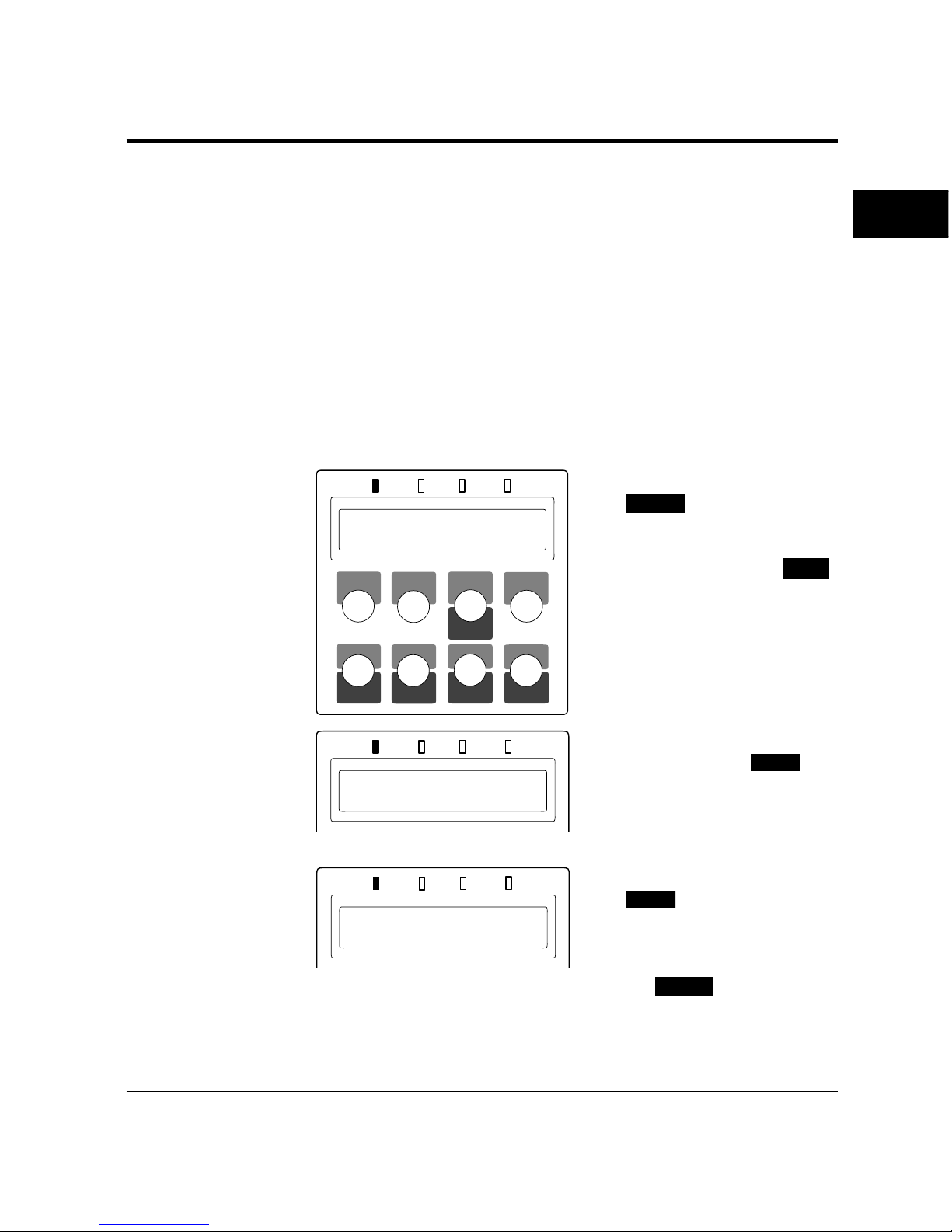
1. Enter setup mode. Press the
READY
button to put the
printer offline (the
ONLINE indicator turns
off). Then, press the
MENU
button briefly six times.
The message display
indicates
SETUP MENU
CONFIG MENU.
2. Select the Personality
menu. Press the
ENTER
button briefly. The message
display indicates
PERSONALITY AUTO*.
3. Select emulation. Press the
ENTER
button briefly. The
option
AUTO changes to
PCL, PS, IBMPRO, EPSON
then back to AUTO. Press
the
READY
button when
the desired option is
displayed.
Page 39

1-22 User’s Manual
The selected emulation is selected (an asterisk is followed). Once you
change the emulation, the other menus automatically change to
reflect the options and functions of the new emulation. For details of
the setup menu, see Chapter 2.
Now that you connected your printer to the parallel port of the
computer, you are ready to install a Windows printer driver into
your computer. The Windows printer driver is essential for
controlling your printer in Microsoft Windows environments.
Several printer drivers are contained in the attached software set
consisting of a CD-ROM and a floppy disk.
Printer drivers in the CD-ROM are:
• Standard drivers for Windows 95/98
• FPS drivers for Windows 95/98
• Standard driver for Windows NT 3.51
• Standard driver for Windows NT 4.0
• FPS driver for Windows NT 4.0
If your printer is 12M, note that the FPS drivers are only available
with an optional FPS card.
Printer drivers in the floppy disk are:
• Standard drivers for Windows 3.x
Standard drivers are to be installed when your printer is used as a
PCL printer and FPS drivers are to be installed when your printer is
used as a PostScript printer.
When you are using Windows 95/98 or Windows NT 4.0, it is
recommended that you should install a printer driver using
MarkVision™ because the printer driver is reinforced with
MarkVision™’s features such as remotely changing settings of a
network printer and checking status of a network printer. For
MarkVision™, see the next section.
Installing a Printer Driver
Installing a
Printer Driver
Page 40
User’s Manual 1-23
GETTING
STARTED
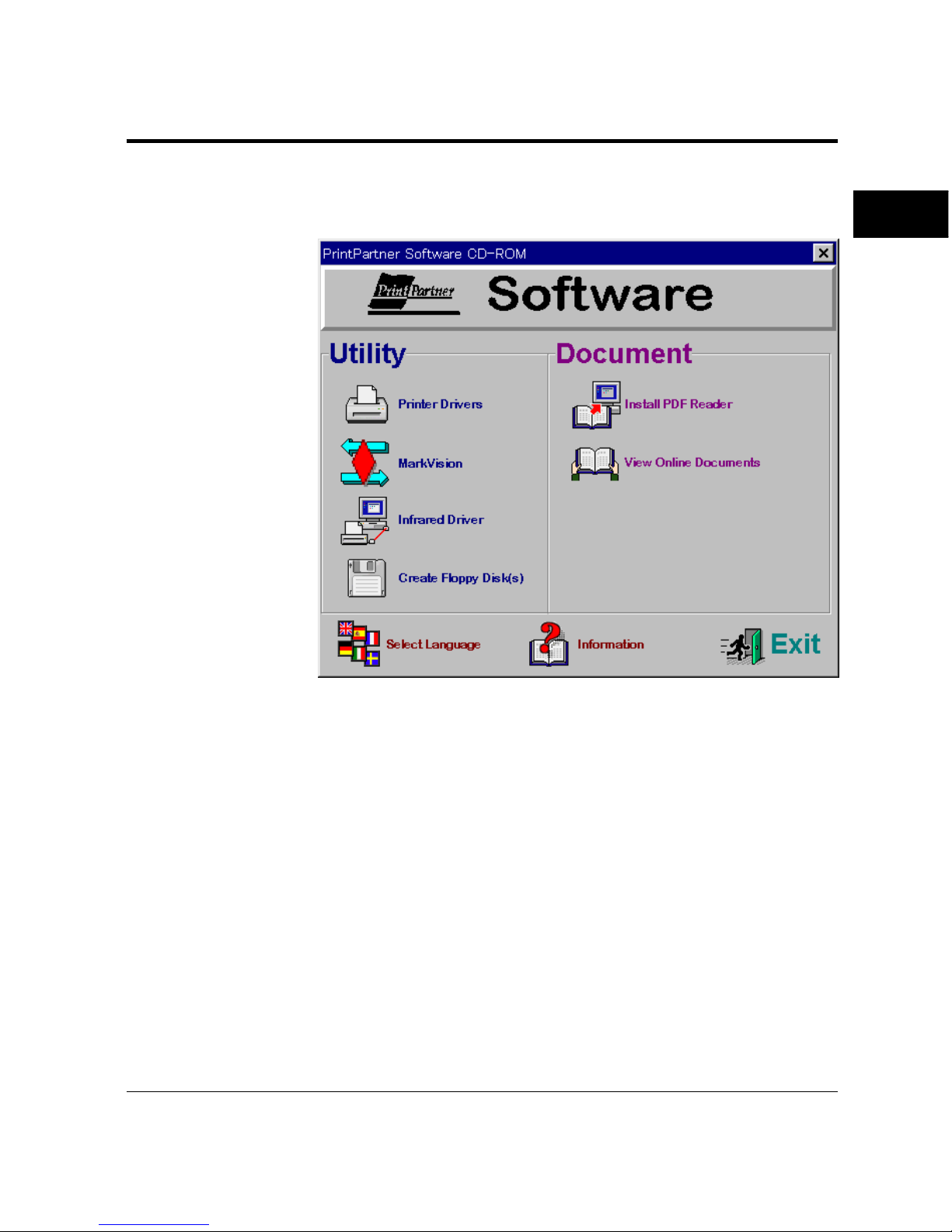
When the CD-ROM is installed, the following menu screen is
displayed in Windows 95/98 or Windows NT 4.0.
Installing a Printer Driver
Get to Know Your Printer Driver
The Printer Driver has two functions:
1. It automatically translates formatting choices, such as tab settings
or boldface type, into commands the printer understands.
2. It allows you to set up the printer according to your needs.
If you encounter problems with this installation, confirm that your
configuration corresponds to the minimum requirements listed on
page vi at the start of this manual. If the configuration corresponds
to these requirements and troubles persist, contact your dealer for
assistance.
Page 41

1-24 User’s Manual
When running application programs under Windows, you select the
printer type in the application program itself before you print a
document.
Important:
If you encounter conflicts with other already installed external drivers
that use bidirectional communication on the Centronics port or with
drivers of other dedicated Windows printers used in parallel with this
printer (conflicts like the failure to establish communication between
the Printer Driver and the printer), remove these from Windows and
reinstall the PrintPartner 12M or 12MX Printer Driver.
Printer Drivers Supplied by the CD-ROM
To install printer drivers contained in the CD-ROM, see the booklet
“Quick Start” enclosed in the CD-ROM envelope.
Printer Drivers Supplied by the Floppy Disk
The floppy disk of the software set contains the Windows 3.x Printer
Standard Driver only. To install it, follow these steps:
1. Start Microsoft Windows 3.x.
2. Insert the floppy disk into drive A.
3. Click “File” and choose “Run”.
4. Type A:INSTALL, then press ENTER.
5. From here, follow the instructions on the screen.
The FUJITSU PrintPartner 12M or 12MX Windows 3.x Standard
Printer Driver is now installed.
For further details, see the driver’s Readme file.
Installing a Printer Driver
✍
Page 42

User’s Manual 1-25
GETTING
STARTED
Installing Other Software
This section provides information about the two kinds of printer
management software contained in the CD-ROM supplied with this
printer. The topics are:
• PPMENU: Enables you to remotely control or configure your
printer’s features from your computer’s screen.
• MarkVision™: Monitors printer status (status is displayed with text
and graphics), displays optional printer’s features, and cooperates
with printer drivers. It also describes the printer control panel
function by which MarkVision™ allows you to remotely operate
your printer from the printer control panel displayed on your
computer’s screen.
Note that PPMENU is available in MS-DOS, PC-DOS, or
Windows DOS prompt environments and MarkVision™ is available
in Windows 95, Windows 98, or Windows NT4.0 environments.
PPMENU
Generally, the printer driver controls the printer. You can also
control the printer using the remote setup utility program called
PPMENU, stored in the attached CD-ROM.
PPMENU allows you to easily change your printer’s features directly
from your computer. You use it to configure your printer to suit the
requirements of your computer, software, and documents to be
printed.
The parameters you can change using PPMENU affect page layout,
font, and printer control. If your software programs have printer
drivers, those printer drivers control the parameters for you.
Therefore, it may not be necessary to change the settings using
PPMENU.
PPMENU needs to be installed only if you will print from DOS or
DOS based applications.
To install PPMENU, see the booklet “Quick Start” enclosed in the
CD-ROM envelope.
For more details and the latest modifications, refer to the
“ReadMe.txt” file concerning PPMENU.
Installing Other
Software
Page 43

1-26 User’s Manual
Lexmark’s MarkVision™
MarkVision™ by Lexmark is an integrated software for managing
printers, contained in the CD-ROM. It has the following main
functions:
• Monitoring the printer
• Displaying the printer status and features (including options) and
statistics
• Providing the printer control panel on the computer’s screen
(Remote control panel)
These functions are most effective and valuable for remote printers in
network environments.
MarkVision™ is automatically activated when an abnormal
condition occurs in the printer. It operates in Windows 95/98
environments only.
The remote control panel is quite a nice function that enables you to
easily and remotely operate the printer even if your printer is set up
remotely. MarkVision™ displays the printer control panel on the
computer’s screen and gives you the exactly same functions as
available with the control panel of the printer. You can perform a
function by clicking a button on the computer’s screen without
pushing a button of the printer’s control panel.
To install MarkVision™, see the booklet “Quick Start” enclosed in
the CD-ROM envelope.
For more details and the latest modifications, refer to the operation
guide PDF document file and the “ReadMe.txt” file concerning
MarkVision™ in the CD-ROM.
Installing Other Software
Page 44

User’s Manual 1-27
GETTING
STARTED
Printing Your First Document
Your printer should be set up and connected to your computer. This
section explains how to test your installation setup by printing a trial
document from an application program under Windows. To test the
printer alone, without your computer, you can use the status report
printing which does not require the use of a computer. See Printing
a Status Report in Chapter 2.
Turn on your printer and observe the initialization sequence. If no
RAM (extra memory) cards have been installed, the sequence lasts
about one minute, during which the following events occur:
• The printer conducts a number of self-checks.
• The main motor rotates to check mechanical functions and clean
the drum.
• The message display indicates READY, indicating the printer is
ready for printing.
The following procedures show you how to print your trial
document.
To print a trial document, follow these steps:
1. Start Windows and a Windows application.
2. Open your trial document.
Select an existing or start a new document. Choose a small
document for the first trial.
3. Select PP12M or PP12MX as the document printer.
In most programs, you make the selection in a print menu.
Consult your program documentation for the exact procedure.
4. If desired, change the font(s) in the document to one of the
fonts offered by your application.
5. Check the printer.
Look in the main window of the Print Manager to make sure the
printer is activated.
6. Print your document.
Start the program. The default paper size is fixed to A4 (for
Europe) or Letter (for the USA).
Printing Your First
Document
Page 45
1-28 User’s Manual
POWER
ONLINE
DATA
ERROR
Printing Your First Document
Adjusting Print Density
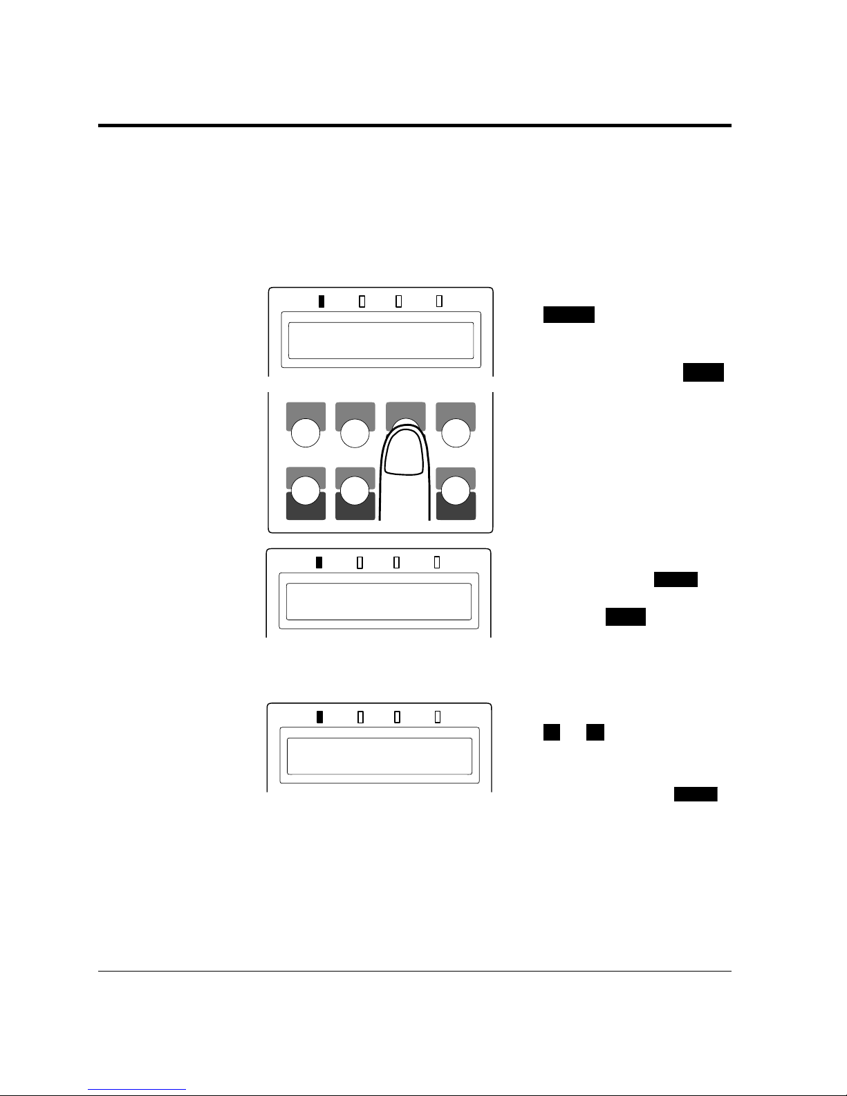
If you feel that the printout is too light or too dark, adjust the print
density from the control panel in setup mode. After making the
adjustment, print your trial document again and check the results.
Use the Toner density menu of the Quality menu as shown below.
1. Enter setup mode. Press the
READY
button to put the
printer offline (the
ONLINE indicator turns
off). Then, press the
MENU
button briefly two times.
The message display
indicates
SETUP MENU
QUALITY MENU.
2. Select the Toner density
menu. Press the
ENTER
button briefly once. Then,
press the
MENU
button
briefly three times. The
message display indicates
TONER DENSITY 5*.
3. Change density. Press the
+
or – button briefly.
The option changes
between
1 (lightest) and 10
(darkest). Press the
ENTER
button when the density
you estimate proper is
displayed.
The selected density is selected (an asterisk is followed). For details of
the setup menu, see Chapter 2.
POWER
ONLINE
DATA
ERROR
TONER DENSITY
5*
READY
POWER
ONLINE
DATA
ERROR
SETUP MENU
QUALITY
MENU
MFF
PAPER SIZEPAPER SIZE
PRINT
FONT
SELF
TEST
RESET
CONT.
ENTER
–
+
MENUREADY
FORM
FEED
RESET
MENU
SELECT
Page 46
User’s Manual 1-29
GETTING
STARTED
If you see a problem with the printed pages other than print density,
see Chapter 5 for possible causes and solutions.
If your document printed successfully, skip the next subsection If
Something Goes Wrong.
If Something Goes Wrong
This section briefly discusses the most common problems you might
encounter. For more complete troubleshooting information, see
Chapter 5. Chapter 5 also describes all printer error and status
indicators.
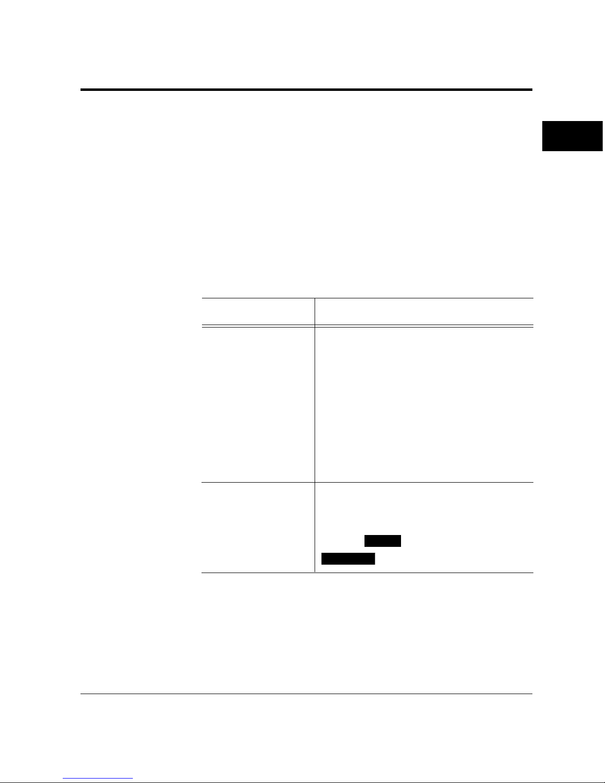
Problem Remedy
No response by printer Ensure that:
• The printer is turned on and online. The
ONLINE indicator should be lit.
• The cable from the computer to the
printer is properly connected at both
ends.
• Your software program has sent the print
data to the printer. Many programs have
a printer control function that shows
print
No printout; DATA The printer has received data from the
indicator on computer but has not printed the page. To
print the page, put the printer offline by
pressing
READY
briefly then press
FORM FEED
.
Printing Your First Document
Page 47

1-30 User’s Manual
Where To Go From Here
Where To Go
From Here
Problem Remedy
Unreadable printout Possible causes and solutions are:
• A wrong printer driver is selected. Select
the PrintPartner 12M or 12MX printer
driver as the document printer.
• The document contains unknown
printer commands. Remove any setup
strings or embedded commands, or print
the document with a Text only or ASCII
text print option.
To help you enhance or customize the printer, the user’s manual
contains the following additional information:
• To get information on how to use the control panel and on
handling various types of paper, see Chapter 2.
• To customize printer defaults, see Chapter 2.
• To install additional memory, see Chapter 3.
• To install an additional interface, see Chapter 3.
• To install an additional paper tray, see Chapter 3.
The FPS card is optional for the PrintPartner 12M and the duplex
unit is optional for the PrintPartner 12MX.
• To install a duplex unit, see Chapter 3.
• To install an FPS card, see Chapter 3.
Page 48

User’s Manual 2-1
PRINTING AND
PAPER HANDLING
2
CHAPTER
Printing and Paper Handling
This chapter provides information you may need for day-to-day
printing. The topics are:
• Control panel tutorial
The tutorial describes the indicators, message display, and buttons.
It includes an example of how to use the control panel.
• Control panel functions
This section describes the functions by buttons.
• Menu functions
This section describes how to use the control panel for customizing
printer defaults.
• Handling paper
This section describes how to print on various types of paper.
This section introduces the printer’s control panel, beginning with a
description of the indicators, message display, and buttons. The
tutorial describes the use of the buttons in some detail and follows
with an example.
The Control Panel
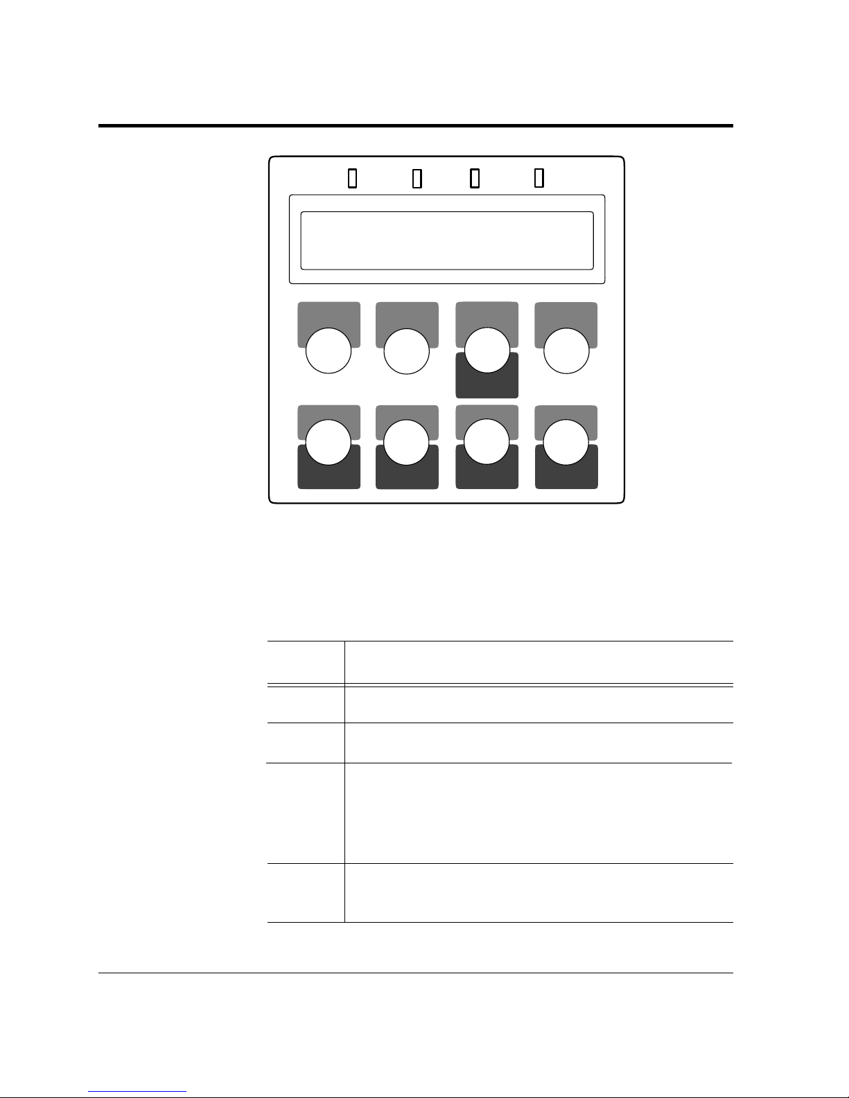
The control panel consists of four indicators, a message display, and
eight buttons. The physical buttons are beneath the LCD display.
The top row of labels represents basic functions. The bottom row of
labels represents secondary functions. See later in this section for a
list of functions.
Control Panel
Tutorial
Page 49
2-2 User’s Manual
Control Panel Tutorial
POWER
ONLINE
DATA
ERROR
MFF
PAPER SIZEPAPER SIZE
PRINT
FONT
SELF
TEST
RESET
CONT.
ENTER
–
+
MENUREADY
FORM
FEED
RESET
MENU
SELECT
Figure 2–1 Control panel
Indicators
The control panel has four labeled LED indicators across the top.
Indicator Meaning
POWER Indicates printer power is on.
ONLINE Indicates the printer is online and ready to print.
DATA Flashes when data is being sent from your computer.
Lights steadily to indicate the printer’s buffer contains
unprocessed data.
ERROR Indicates a printer error has occurred. Details are
indicated by the message display.
Page 50
User’s Manual 2-3
PRINTING AND
PAPER HANDLING
Control Panel Tutorial
Message Display (LCD)
The message display uses a liquid-crystal display representing status
and errors by two lines of sixteen characters. In operating mode, it
may show:
• What the printer is doing
• Whether the printer is ready to print
• When paper should be added
• When paper should be manually inserted
• When the developer unit needs to be replaced
• When the drum unit needs to be replaced
• An error message condition such as paper jam
Important:
A "Ready" message means the printer has no data to print without
any errors and the
READY
button is not pressed. "Not Ready" means
the printer detected an error or the
READY
button was pressed in the
Ready state.
Error messages inform you of conditions requiring your attention,
such as
TRAY
n
PAPER OUT, COVER OPEN, or PAPER JAM
n
.
They also warn you of hardware problems, such as
FUSER FAILURE
or BD CYCLE ERROR. The TONER LOW n message informs you
that the developer unit is short of toner. See Chapter 5 for a
complete list of messages and explanations.
In tray select mode or MFF paper size mode, the message display
shows the selected tray or the selected paper size respectively. In
menu mode, the message display shows menu items and option
selections. These modes are explained later in this chapter.
Buttons
One or two functions are assigned to a button. To use the functions
represented by the top labels, simply press the button. To use the
functions represented by the bottom labels, press and hold down the
button for five or more seconds. The following tables summarizes the
functions.
✍
Page 51
2-4 User’s Manual
Control Panel Tutorial
Pressing the button briefly
Except for the
READY
button, the following buttons are also valid
when the printer is offline.
Button (top label) Function
READY
Switches the printer between online and offline.
FORM FEED
Performs a form feed to print the remaining data.
CONT.
Clears a recoverable error and continues printing.
SELECT
Puts the printer in tray select mode which allows
you to select the paper tray to be used.
MENU
Puts the printer in setup mode.
ENTER
Selects the displayed option as the printer default.
This button and the two buttons below are valid
in setup, tray select, or MFF paper size mode.
+
Displays the next option.
–
Displays the previous option.
Pressing and holding down the button for five or more seconds
The following buttons are also valid when the printer is offline.
Button (bottom label) Function
RESET
Clears the buffer of any print data and puts the
printer through its initialization sequence.
RESET MENU
Besides the above reset function, resets all printer
operation options to their factory default values
except interface settings (parallel menu, serial
menu, and network menu).
MFF PAPER SIZE
Puts the printer in MFF paper size mode, which
allows you to select the paper size to be used.
SELF TEST
Selects the self test menu, which lists printer
operation options currently selected.
PRINT FONT
Selects the print font menu, which lists the fonts
currently available.
Page 52

User’s Manual 2-5
PRINTING AND
PAPER HANDLING
Control Panel Functions
Changing Message Language (
MENU
)
You can select a language used for control panel messages. Selectable
languages are English, French, German, Italian, Spanish, and Swedish.
To select a language, follow these steps:
1. Turning the printer on while pressing
MENU
.
The message
C.P.LANGUAGE ENGLISH appears after printer
initialization.
2. Press the + or – button until the desired language appears.
Press the
ENTER
button.
The asterisk appears after the language, indicating the language is
selected.
3. Save the selection.
Pressing the
READY
button saves the new setting and returns the
printer to the ready state. The printer will display the selected
language for messages.
Printing Data Remaining in the Buffer (
FORM FEED
)
Pressing
FORM FEED
tells the printer to advance to the next page.
The practical effect is to print any data remaining in the buffer. For
example, the buffer might contain data from an interrupted print
job. When the buffer contains residual data, the control panel DATA
indicator is steadily lit.
Clearing an Error Condition to Continue Printing (
CONT.
)
When a recoverable error occurred, pressing
CONT.
clears the error
condition and continues printing. For example, you can resume
printing after adding paper in response to a
TRAY1 PAPER OUT
message. You can use
CONT.
to ignore a message such as Load
TRAY1 A4. For example, you might want to print a page with A4-
size format on a letter-size sheet.
CONT.
also allows you to override
the INSERT A4 prompt when feeding paper manually. By pressing
CONT.
, the printer prints from tray1 instead.
Control Panel
Functions
Page 53

2-6 User’s Manual
Clearing the Buffer and Reinitializing the Printer (
RESET
)
Pressing and holding down
RESET
for five or more seconds clears the
print buffer and tells the printer to initialize itself. You might use
this function if you cancel a print job in the middle and want to clear
the printer and start over. In this case, permanently downloaded
fonts are removed by the initialization process. You must download
the fonts again.
Clearing EEPROM (
RESET
)
Turning the printer on while pressing and holding down
RESET
resets the menu settings of EEPROM to the factory default values.
The message display indicates
EEPROM CLEAR for a second,
WARMING UP, then READY (about a minute after). Unlike resetting
menu by
RESET MENU
, this function also resets the interface settings.
Use this function to return all menu settings to the original standard
conditions.
Control Panel Functions
Page 54
User’s Manual 2-7
PRINTING AND
PAPER HANDLING
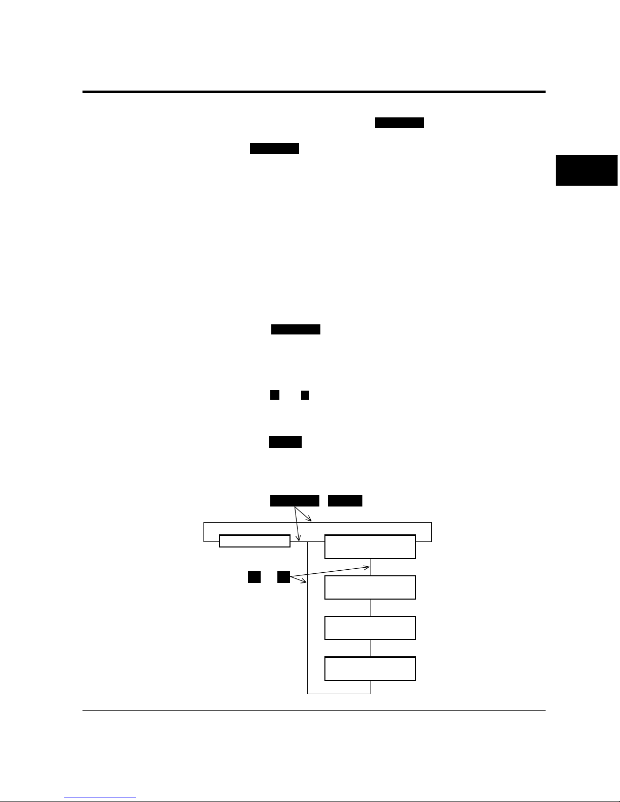
Selecting the Self Test Menu (
SELF TEST
)
Pressing
SELF TEST
puts the printer into the self test menu which
allows you to print a status report which lists printer operation
options currently selected in the selected emulation.
When the service life of the developer unit or the drum unit is
expired or when toner of the developer unit runs short, the status
report includes that information.
To select the self test menu and print a status report, follow these
steps:
1. Make sure that the message display indicates
READY with the
ONLINE and DATA indicators off.
2. Press the
SELF TEST
button for five or more seconds.
The message changes to
PCL PAGE CONFIG START.
3. Select a desired emulation.
Press the
+
or – buttons until the desired emulation appears.
4. Start printing.
Press the
ENTER
button. The message display indicates SELF
TEST and the DATA indicator flashes, then a status report page is
printed.
SELF TEST ( ENTER )
+ –
➤
➤
➤➤
➤
➤
➤
➤
➤
➤
READY
PCL PAGE CONFIG
START
FPS PAGE CONFIG
START
or
For PrintPartner 12MX,
this is displayed .
Control Panel Functions
EX PAGE CONFIG
START
PP PAGE CONFIG
START
Page 55
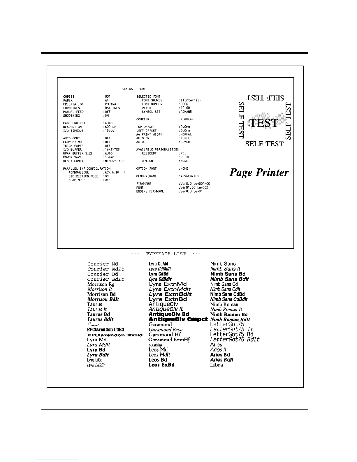
2-8 User’s Manual
Control Panel Functions
Figure 2–2 Status report (PCL emulation)
Page 56
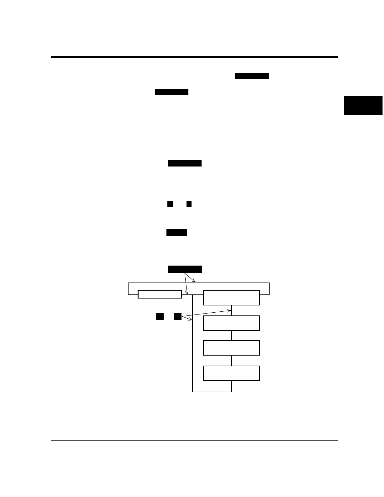
User’s Manual 2-9
PRINTING AND
PAPER HANDLING
PRINT FONT
+ –
➤
➤
➤➤
➤
➤
➤
➤➤
➤
Selecting the Font Print Menu (
PRINT FONT
)
Pressing
PRINT FONT
puts the printer into the print font menu which
allows you to list the fonts available in the selected emulation.
To select the print font menu and print the font list, follow these
steps:
1. Make sure that the message display indicates
READY with the
ONLINE and DATA indicators off.
2. Press the
PRINT FONT
button for five or more seconds.
The message changes to
PCL FONT LIST START.
3. Select a desired emulation.
Press the
+
or – buttons until the desired emulation appears.
4. Start printing.
Press the
ENTER
button. The message display indicates PRINT
FONT and the DATA indicator flashes, then a font report page is
printed.
Control Panel Functions
READY
PCL FONT LIST
START
FPS FONT LIST
START
or
For PrintPartner 12MX,
this is displayed .
EX FONT LIST
START
PP FONT LIST
START
Page 57
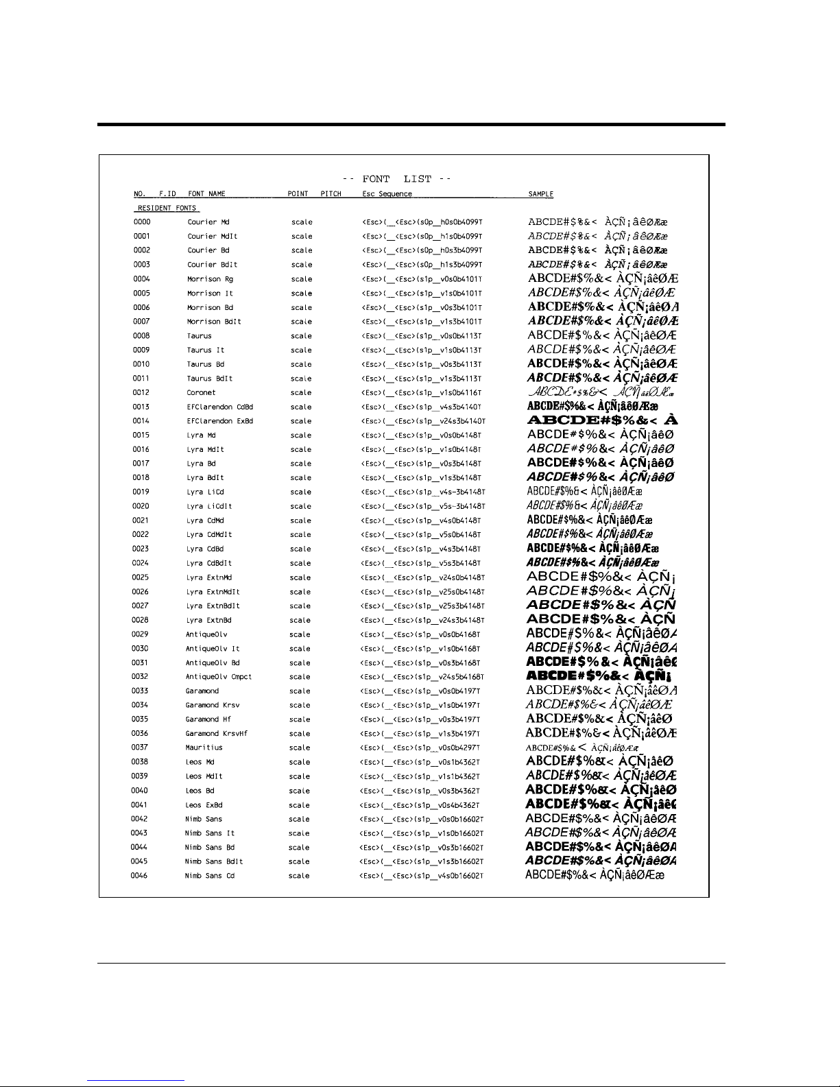
2-10 User’s Manual
Control Panel Functions
Figure 2–3 Font report-first page (PCL emulation)
Page 58

User’s Manual 2-11
PRINTING AND
PAPER HANDLING
Selecting Paper Tray, MFF, or Manual Feed Mode (
SELECT
)
Pressing
SELECT
puts the printer in tray select mode which allows
you to set paper sources in locked or unlocked status. In the locked
status, the paper source selection is fixed. In the unlocked status, the
paper source is automatically switched to another source in a certain
condition (auto tray selection). The paper sources are tray 1, tray 2
(if installed), MFF, and MFF in manual feed mode.
MFF
The MFF operation is controlled by MFF mode in which “first”
mode and “cassette” mode are provided.
First mode
The MFF has the highest priority and is selected first of all if
printing is requested. You do not need to set the paper size of the
MFF. (The MFF paper size menu is disabled.) The printer starts
printing assuming that the loaded paper has the job-specified size
of paper.
If you are printing using tray 1 or 2 with this mode set, you can
immediately switch the tray to the MFF just by putting paper on
the MFF. This is called on-demand printing.
Cassette mode (default)
The MFF is controlled in the same manner as for other paper
trays. However, it has the lowest priority as compared with trays 1
and 2. You must set the physical size of the paper loaded on the
MFF, using the MFF paper size menu. If the MFF paper size does
not match the job-specified size, a paper mismatch error occurs.
MFF in Manual Feed Mode
The MFF can also operate in manual feed mode in which you can
feed paper manually in response to a control panel message.
Operation slightly differs with the two modes of the MFF.
Control Panel Functions
Page 59

2-12 User’s Manual
In first mode
If paper is already loaded on the MFF, it is picked without the
paper insertion request message. If paper is not loaded on the
MFF, the paper insertion request message is displayed.
In cassette mode
Whether or not paper is loaded on the MFF, the paper insertion
request message is displayed. If paper is already loaded on the
MFF, printing starts after you press
CONT.
. If paper is not loaded
on the MFF, printing starts when you load paper.
You can select two or three paper sources at a time, but must select at
least one paper source. Tray 1, tray 2 (if installed), and MFF cassette
mode are all selected as factory default.
When two or three paper sources are selected for auto tray selection
(unlocked) and when a paper source runs out of paper or a paper
miss match error occurs, the printer switches the paper source for
another one.
To select a paper source for auto tray selection, follow these steps:
1. Make sure that the message display indicates
READY with the
ONLINE and DATA indicators off.
2. Press the
SELECT
button briefly.
The message changes to
TRAY TRAY1*. The asterisk means
that tray 1 is selected for auto tray selection (unlocked).
3. Select or deselect a paper source.
Tray 2 is valid if it is installed. Pressing the
ENTER
button in this
condition makes the asterisk disappear. Tray 1 is deselected.
Pressing the
ENTER
button again makes the asterisk reappear.
Tray 1 is selected.
Control Panel Functions
Page 60
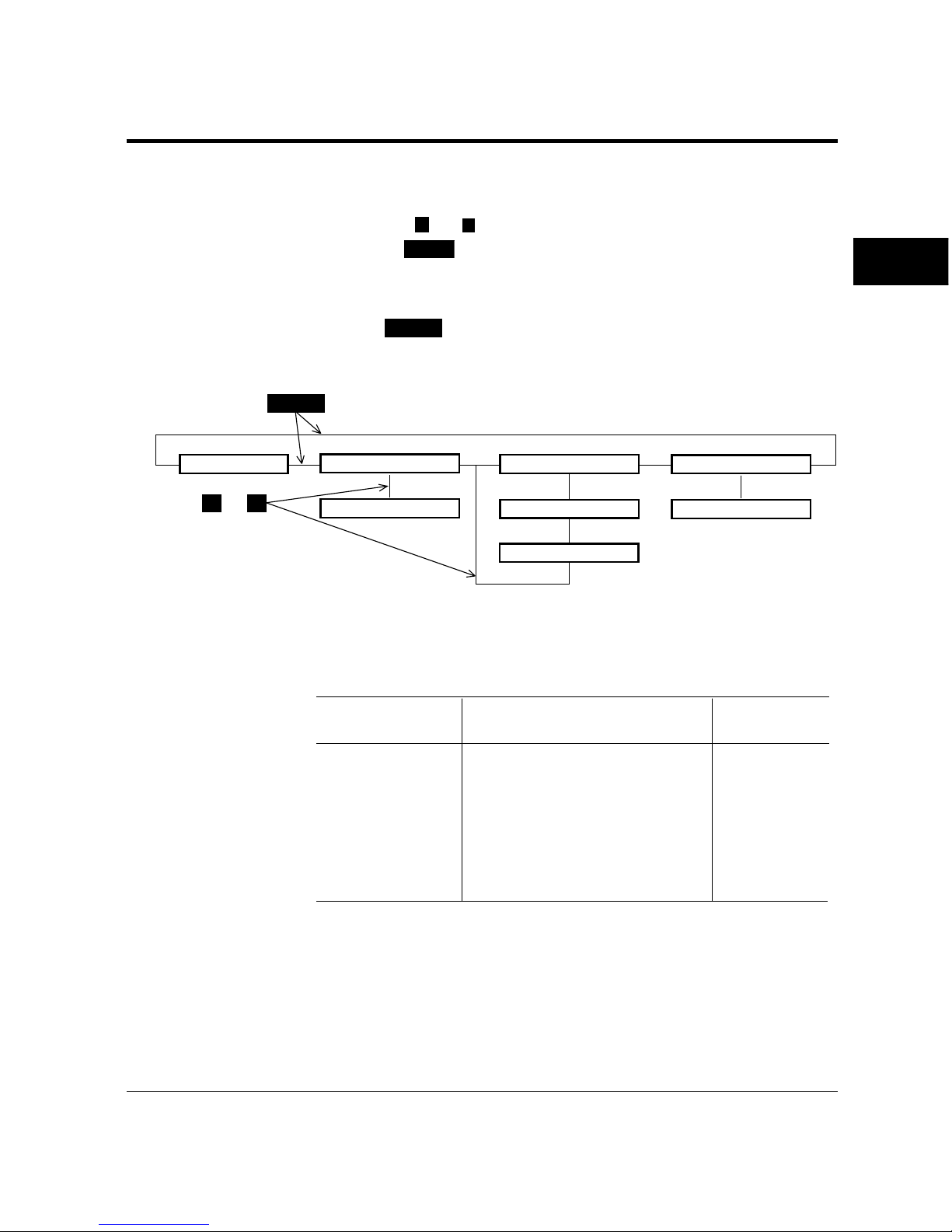
User’s Manual 2-13
PRINTING AND
PAPER HANDLING
4. Select or deselect other paper sources.
Press the
+
or – buttons briefly to display another paper source.
Use the
ENTER
button in the same way as described above.
5. Save the selections.
Press
READY
button to save the new settings and return to the
ready state.
SELECT
+ –
➤
➤
➤➤
➤
➤
➤
➤
➤
➤
➤
➤
➤
➤
Control Panel Functions
READY
MANUALFEED OFF*
TRAY TRAY1*
MANUALFEED ON
TRAY TRAY2*
TRAY MFF*
or
MFF MODE CASSETTE*
MFF MODE FIRST
(†)
According to tray selection, the INTRAY LOCK status printed in a
status report changes as follows:
Tray selection Intray lock status Remarks
TRAY TRAY1 INTRAY1: LOCKED
TRAY TRAY1* INTRAY1: UNLOCKED
TRAY TRAY2 INTRAY2: LOCKED
TRAY TRAY2* INTRAY2: UNLOCKED
TRAY MFF (†) INTRAYMFF: LOCKED
TRAY MFF* (†) INTRAYMFF: UNLOCKED
† When MFF MODE = FIRST, TRAY MFF is not displayed or
selected.
Page 61
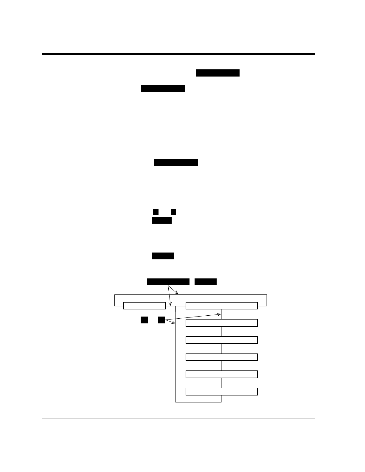
2-14 User’s Manual
MFF PAPER SIZE( SELECT
)
+ –
➤
➤
➤➤
➤
➤
➤
➤
➤
➤
➤
➤
➤
➤
Control Panel Functions
Setting MFF Paper Size (
MFF PAPER SIZE
)
Pressing
MFF PAPER SIZE
puts the printer in MFF paper size mode
which allows you to inform the controller of the physical paper size
used in the MFF. You must select the size of paper currently loaded
in the MFF. This menu is not available for the PrintPartner 12M.
To select a paper size, follow these steps:
1. Make sure that the message display indicates READY with the
ONLINE and DATA indicators off.
2. Press the
MFF PAPER SIZE
button for five or more seconds.
The message changes to MFF PAPER A4*. The asterisk
means that A4 size is selected for the MFF.
3. Select a desired paper size.
Press the
+
or – buttons until the desired paper size appears.
Press the
ENTER
button. The asterisk appears and the paper size is
selected.
4. Save the selection.
Press the
READY
button to save the new setting and return to the
ready state.
READY
MFF PAPER LETTER*
MFF PAPER XXXXX
or
MFF PAPER EXECUTIVE
MFF ENVELOPE COM10
MFF ENVELOPE XXXXX
MFF ENVELOPE B5
XXXXX: LEGAL
A4
A5
JISB5
XXXXX: MONARCH
C5
DL
Page 62

User’s Manual 2-15
PRINTING AND
PAPER HANDLING
Selecting the Thickness
Control
Menu
(
SELECT
)
This printer has the thickness control menu which allows you to
select one of the two thickness control modes for adjusting the
printer for paper thickness. One is the normal mode (factory default)
and the other is the extension mode.
The normal mode allows you to print thick paper, but has only one
choice between two options (ON for thick paper and OFF for
ordinary paper). This choice is common to all paper sources (tray 1,
tray 2 (if installed), and MFF.
The extension mode allows you to print several kinds of thin paper,
thick paper, and thick envelopes for every paper source (eight options
for every tray 1, tray 2 (if installed), or MFF.
When one mode is selected, you cannot use the other mode.
To select a thickness control mode, follow these steps:
1. Turning the printer on while pressing and holding down
SELECT
.
The message indicates
THICKNESS CONTRL NORMAL* after
printer initialization. The asterisk means that normal mode is
selected for paper thickness.
2. Select a desired mode.
Press the
+
or – button until the desired mode appears. Press
the
ENTER
button. The asterisk appears and the mode is selected.
3. Save the selection.
Press the
READY
button to save the new setting and return to the
ready state.
This selection remains even if you turn the printer off.
Control Panel Functions
Page 63
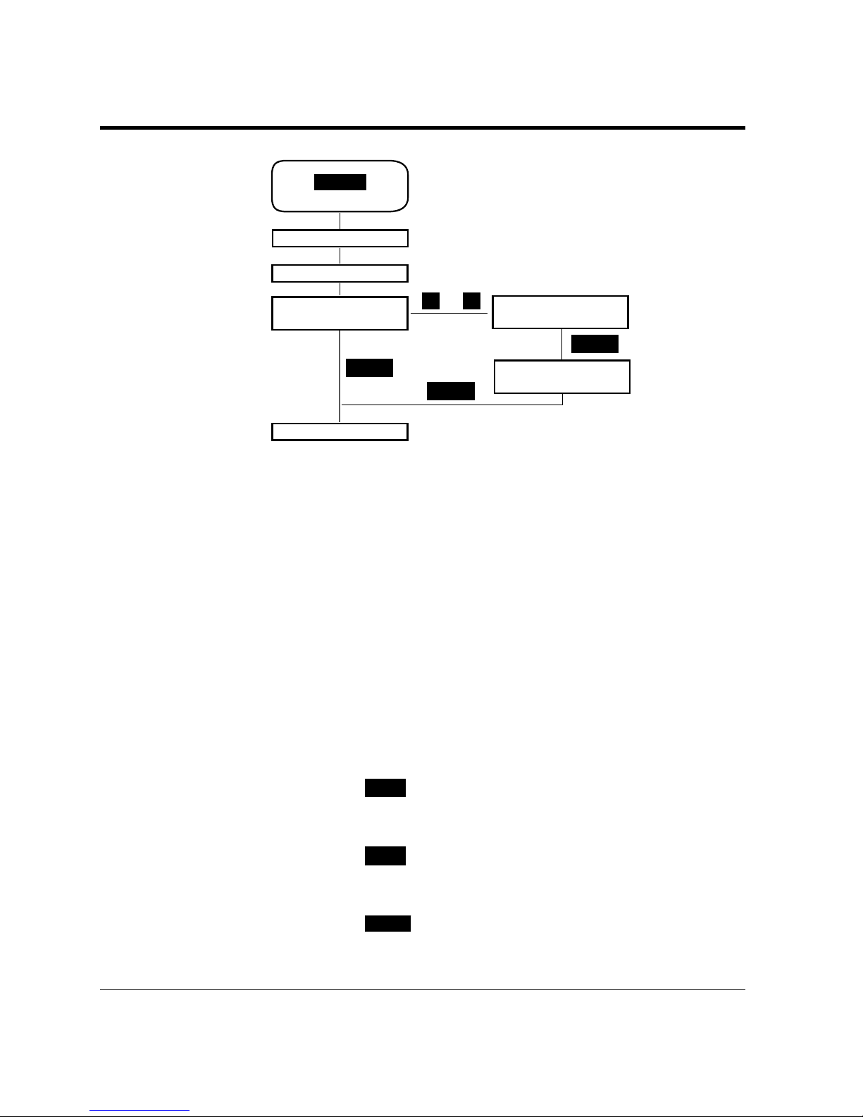
2-16 User’s Manual
When you select a mode, the contents of the Quality menu changes
according to the mode selected.
When the thickness control is normal, only the Thick Paper item
appears for paper thickness. This item has two options, OFF and
ON.
When the thickness control is extension, the Tray1 Media, Tray2
Media, and MFF Media items appear for paper thickness. Tray2
Media appears when tray 2 is installed. Each item has eight options
from -2 to 5.
To select an option in thickness control mode, follow these steps:
1. Make sure that the message display indicates READY with the
ONLINE and DATA indicators off.
2. Press the
MENU
button briefly.
The message changes to
SETUP MENU PAGE FORMAT MENU.
3. Press the
MENU
button.
The message changes to
SETUP MENU QUALITY MENU.
4. Press the
ENTER
button.
The message changes to
SMOOTHING ON*.
+–
➤
➤ ➤
➤
➤
➤
➤
➤
ENTER
READY
READY
or
Power on with
SELECT
pressed
READY
<<<INITIALIZE>>>
WARMING UP
THICKNESS CONTRL
NORMAL*
THICKNESS CONTRL
EXTENSION
THICKNESS CONTRL
EXTENSION*
Control Panel Functions
Page 64

User’s Manual 2-17
PRINTING AND
PAPER HANDLING
5. Press the
MENU
button three times.
The message changes to
THICK PAPER OFF* when the
thickness control is normal, or
TRAY1 MEDIA 0* when the
thickness control is extension.
6. When the thickness control is extension, press the
MENU
button until the desired item appears.
The message changes to
TRAY2 MEDIA 0*, or MFF MEDIA
0*.
7. Select a desired option.
Press the + or – button until the desired option appears. Press
the
ENTER
button. The asterisk appears and the option is selected.
When the thickness control is extension, repeat steps 6 and 7.
8. Save the selection.
Press the
READY
button to save the new setting and return to the
ready state.
This selection remains even if you turn the printer off.
Each option means as follows:
When the thickness control is normal:
Off: Ordinary paper
On: Thick paper
When the thickness control is extension:
-2: Thin paper when resulting in waving
-1: Thin paper when resulting in light printing with duplex unit
0: Ordinary paper
1: Thick paper
2: Thick envelope when resulting in toner easily coming off
3: Thick envelope when resulting in light printing
4: Thick rough paper when resulting in smudging
5: Thick rough paper when resulting in light printing
The mode number increases according to paper thickness and
roughness. Select one of the underlined numbers in the normal usage.
Control Panel Functions
Page 65
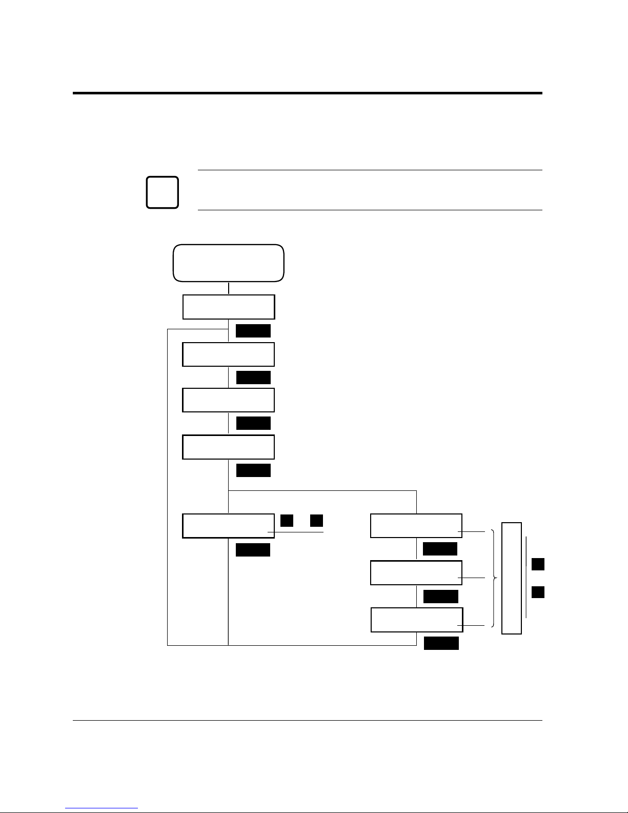
2-18 User’s Manual
Try several options and select an appropriate option that results in
the most satisfied print quality. However, use the normal mode
basically.
Caution:
Turn the mode off or reset it to 0 after printing thick or thin paper.
+
–
➤
➤ ➤
➤
➤
➤
➤
MENU
ENTER
MENU
➤
MENU
➤
MENU
➤
➤
MENU
➤
MENU
MENU
➤
➤
➤
+–
➤
➤
-2
-1
0
1
2
3
4
5
SETUP MENU
QUALITY MENU
SMOOTHING
ON*
RESOLUTION
600*
ECONOMY MODE
OFF*
THICK PAPER
OFF*
TRAY1 MEDIA
0*
TRAY2 MEDIA
0*
MFF MEDIA
0*
ON
or
or
Enter Menu mode
and
select Quality menu
When
THICKNESS
CONTRL is
EXTENSION.
When
THICKNESS
CONTRL is
NORMAL.
☞
Control Panel Functions
Page 66

User’s Manual 2-19
PRINTING AND
PAPER HANDLING
Menu Functions
Menu Functions
Selecting Menu Option (
MENU
) and Resetting Menu (
RESET MENU
)
Pressing
MENU
briefly puts the printer in menu mode which allows
you to set up the printer, for example, selecting a paper size,
changing a font, and adjusting serial interface parameters. You can
select options from the menu by using the four buttons,
MENU
, +,
–
, and
ENTER
.
Pressing
RESET MENU
for five or more seconds in menu mode resets
all parameters to the factory default values except interface settings
(parallel menu, serial menu, and network menu).
The following section briefly explains the menu mode and its operation.
The menu mode allows you to change your printer’s defaults using
the four buttons on the control panel. You can use the control
panel's menu mode to configure your printer to suit the
requirements of your computer, software, and documents.
Menu Structure and How to Use Control Panel Buttons
The menu mode is structured as a tree consisting of submenus,
items, and options. The following example shows a small portion of
the tree and illustrates how the four buttons work.
In the example:
Submenus are
PAGE FORMAT MENU and QUALITY MENU. Items
are C
OPIES, PAPER, and SMOOTHING. Options are 001, 002,
LETTER, LEGAL, ON, and OFF.
MENU
selects menu mode when the printer is ready and offline.
Once the printer is in menu mode,
MENU
selects the first submenu
and moves you right to the next submenu. If you are on the last
submenu, pressing
MENU
causes the printer to return offline ready.
When a submenu is selected,
ENTER
selects the first item of the
submenu. Once the first item is selected,
MENU
moves you right to the
next item, regardless of an option selected. If you are on the last item,
pressing
MENU
causes the printer to return to the original submenu.
Page 67
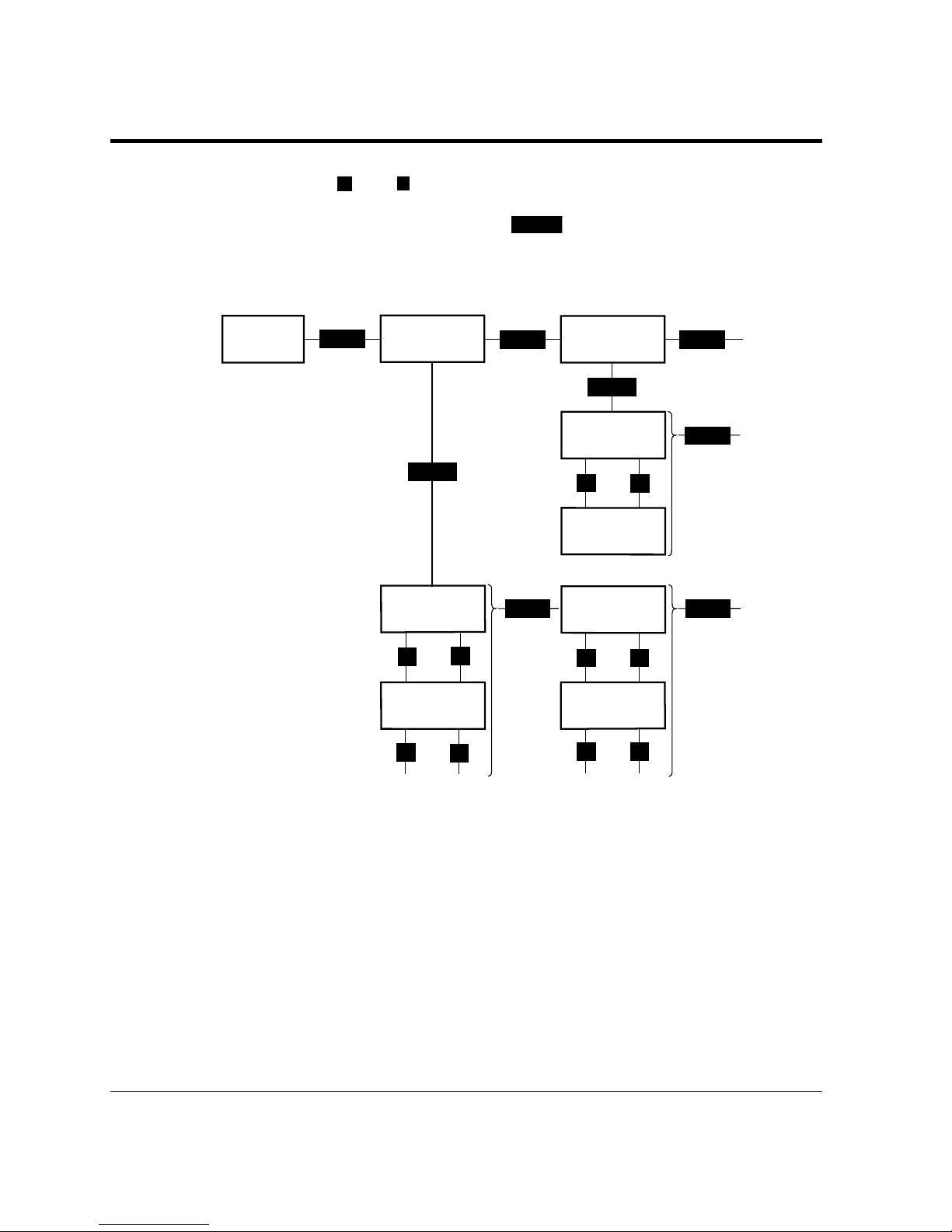
2-20 User’s Manual
ENTER
+
–
MENU
MENU MENU
➤➤➤
ENTER
➤
➤
MENU
+
+
+
+
–
–
–
–
➤
➤
➤➤➤
➤
➤
➤➤➤
➤
MENU
➤
MENU
➤
Menu Functions
SETUP MENU
QUALITY MENU
PAPER
LETTER*
PAPER
LEGAL
SMOOTHING
ON*
SETUP MENU
PAGE FORMAT MENU
COPIES
001*
COPIES
002
READY
SMOOTHING
OFF
Use + and – to move up and down the options list.
When an item is displayed,
ENTER
selects that option (adds an
asterisk after the option indicating that the option is stored in RAM).
Submenus, Items, and Options
The following table shows all of submenus and items and summary
of options displayed on the message display in menu mode. The
display initially shows the factory default option followed by an
asterisk (underlined in the table).
1st submenu
1st item
1st option
(Default )
2nd submenu
To 3rd
submenu
2nd item
2nd option
To or from
3rd option
To 3rd item
1st item
To 2nd item
1st option
(Default )
2nd option
To or from
3rd option
Page 68
User’s Manual 2-21
PRINTING AND
PAPER HANDLING
Menu Functions
Submenu (bold)/Item
Page format menu
Copies
Paper/Envelope
Custom size X
Custom size Y
Orientation
Form lines
Page protect
Duplex mode
Bind
Quality menu
Smoothing (*4)
Resolution (*5)
Economy mode
Toner density
Thick paper (*6)
Tray1 media (*7)
Tray2 media (*7)
MFF media (*7)
PCL font menu
Font source
Font number
Pitch size (*9)
Point size (*10)
Symbol set
Courier
PCL menu (*11)
Top offset
Left offset
A4 print width
Auto attach FF
Auto CR
Auto LF
Options
001, 002, 003, ..., 999 (pages)
A4, A5, JIS B5, Letter, Legal, Executive (*1)
A6, COM10, Monarch, C5, DL, B5
69 to 229 (mm)
127 to 356 (mm)
Portrait, Landscape
005, 006, 007, ..., 060, ..., 128 (lines/page) (*2)
Auto, On
Off, On (*3)
Long edge, Short edge (*3)
On, Off
600, 300, 1200 (dpi)
Off, On
1, 2, ..., 5, ..., 9, 10
Off, On
-2, -1, 0, 1, 2, 3, 4, 5
-2, -1, 0, 1, 2, 3, 4, 5
-2, -1, 0, 1, 2, 3, 4, 5
Internal, Soft, SIMM (*8)
000, 001, 002, 003, ..., N (depending on the font
source, max. 999)
0.44, 0.45, 0.46, ..., 99.99 (characters/inch)
4.00, 4.25, 4.50, 4.75, 5.00, ..., 999.75 (point)
Roman8, ISOL1, ISOL2, ISOL5, PC8, PC8-DN,
PC850, PC852, PC8TK, ..., WingDings
Regular, Dark
-25.0, -24.9, -24.8, ..., 00.0, ..., +24.9, +25.0 (mm)
-25.0, -24.9, -24.8, ..., 00.0, ..., +24.9, +25.0 (mm)
Normal, 80 columns/line
No, Yes
LF, LF+CR
CR, CR+LF
Page 69

2-22 User’s Manual
Menu Functions
Submenu (bold)/Item
IBM Pro. menu
Symbol set
Nation
Cpi
Lines per inch
Print attribute
Slashed zero
Line width
Auto LF on CR
Auto CR on LF/FF
Epson menu
Symbol set
Nation
Characters per inch
Lines per inch
Print attribute
Slashed zero
Line width
Auto LF on CR
Auto CR on LF/FF
FPS menu (*12)
Jam recovery
Print FPS errors
Job timeout
Wait timeout
Manual timeout
Mode selection
Config menu
Personality
Auto continue
I/O timeout (*14)
I/O buffers
Power save
Toner low
Pre pick
Soft switch
SW1-0 to SW1-7
SW2-0 to SW2-7
SW3-0 to SW3-7
SW4-0 to SW4-7
Options
IBM CS2, IBM CS1, Epson STD ITAL
USA, Portugal, Norway/Denmark, France/Canada,
PC850 Multilan, ISO 8859.1
10 cpi, 12 cpi, 17.1 cpi, 20 cpi
6 lpi, 8 lpi, 12 lpi
Normal, Emphasized, Italics
Normal, Slashed
80 characters, 78 characters
Disable, Enable
Disable, Enable
IBM CS2, IBM CS1
USA, France, Germany, England, Denmark,
Sweden, Italy, Spain1, Japan, Norway, Denmark2,
Spain2, Latin-America, ISO 8856.1
10 cpi, 12 cpi, 17.1 cpi, 20 cpi
6 lpi, 8 lpi, 12 lpi
Normal, Emphasized, Italics
Normal, Slashed
80 characters, 78 characters
Disable, Enable
Disable, Enable
Off, On
On, Off
0, 10, 11, 12, ..., 298, 299, 300 (0: no check)
0, 10, 11, 12, ..., 298, 299, 300 (0: no check)
0, 10, 11, 12, ..., 60, ..., 298, 299, 300 (0: no check)
Auto mode, Memory mode, Speed mode (*13)
Auto, PCL, PS, IBMPRO, EPSON (*12)
Off, On, Ext
5, 6, 7, ..., 15, ..., 298, 299, 300 (seconds)
Auto, 32K, 64K, 128K, 256K (bytes)
On after 15 min, 30 min, 60 min, 120 min, Off
Stop, Continue
Off, On
SW1, SW2, SW3, SW4
Off, On
Off, On
Off, On
Off, On
Page 70

User’s Manual 2-23
PRINTING AND
PAPER HANDLING
*1 Default is Letter or A4. For example, Letter for U.S. customers
and A4 for European customers. To print on legal-size paper at
600 dpi in FPS emulation, the total RAM capacity must be 12M
bytes or more.
*2 This is for Letter and portrait. It automatically changes
depending on paper size and page orientation.
*3 Valid when a duplex unit is installed (12MX only)
*4 Makes the contours of objects appear smoother than normally
possible with the printers standard resolution. Actual resolution
depends on emulations and resolutions selected in menu mode.
*5 Actual resolution depends on emulations selected in menu mode.
*6 Displayed when the thickness control is normal (factory default).
*7 Displayed when the thickness control is extension. Tray2 media
is displayed when tray 2 is installed.
*8 Displayed when soft fonts are downloaded or a font SIMM card
is installed
*9 Displayed when the selected font is a scalable and fixed-spacing
one. The default depends on a selected font.
*10 Displayed when the selected font is a scalable and proportional-
spacing one. The default depends on a selected font.
*11
Effective when PCL jobs are being executed. These values are
used as defaults of top and left offset specifications in PCL mode.
Menu Functions
Submenu (bold)/Item
Parallel menu
Acknowledge (*15)
Bi-direction
NPAP mode
Serial menu (*16)
Baud rate
Pacing
DTR polarity
ROBUST XON
Network menu (*17)
NPAP mode
Bootp
IP address
IP netmask
IP gateway
Clear warning
<Clear warning>
Options
Mode1, Mode2, Mode3
On, Off, ECP
Auto, On, Off
2400, 4800, 9600, 19200, 38400, 57600
DTR, Xon/Xoff
Hi, Low
On, Off
Auto, On
No, Yes
###. ###. ###. ### (### = 0, 1, 2, ..., 255) (*18)
###. ###. ###. ### (### = 0, 1, 2, ..., 255) (*18)
###. ###. ###. ### (### = 0, 1, 2, ..., 255) (*18)
Shows the printing component to be replaced.
Developer unit, Drum unit
Page 71

2-24 User’s Manual
*12 PS is displayed when the FPS (standard for 12MX and option
for 12M) is selected for personality. In FPS emulation, the total
RAM capacity must be:
• 12M bytes or more to print on legal-size paper at 600 dpi
• 16M bytes or more to print at 1200 dpi
*13 If the total capacity of memory is 11M bytes or less with
memory mode selected, duplex printing is restricted as follows:
• Printing is done on one side and paper is ejected to the facedown stacker with the printed side up.
• Setting “jam recovery = on” in FPS menu is ignored.
• The number of copies in page format menu is fixed to 1.
*14
This is essential for sharing the printer among multiple computers.
*15 This is for the parallel interface.
*16 Displayed when a serial interface board is installed
*17 Displayed when a network interface board is installed
*18 Consists of four parameters. The one followed by < can be
changed.
Menu Items
The following briefly explains each item of the menu mode.
Page format menu
Copies The number of copies the printer prints from
each page
Paper/Envelope A paper size or envelope size to be used by the
printer
Custom size X Length of irregular-sized paper to be used by
the printer
Custom size Y Width of irregular-sized paper to be used by
the printer
Orientation A printing direction
Form lines The number of lines printed per page
Page protect Whether a block of printer memory is reserved
exclusively for text and graphics data,
especially for printing dense text or complex
graphics, to prevent memory overflow errors.
However, it reduces the amount of printer
memory available for downloadable fonts.
Duplex mode Two-sided printing mode (12MX only)
Binding
Where an extra area for fastening pages is located,
short or long edge of a page (12MX only)
Menu Items
Page 72

User’s Manual 2-25
PRINTING AND
PAPER HANDLING
Menu Items
Quality menu
Smoothing Whether the edge smoothness and slant line
thickness correction technology is applied
(improves resolution to 1200 dpi class) Actual
resolution depends on emulations and
resolutions selected in menu mode.
On 1200 dpi with 1200 dpi resolution and PCL6
or PS emulation selected
600 dpi in other cases
Off Follows specifications of the next resolution.
Resolution The number of dots printed per inch. Actual
resolution depends on selected emulations.
300 dpi 300 dpi in all emulations
600 dpi 300 dpi in IBM or EPSON emulation
600 dpi in other emulations
1200 dpi 300 dpi in IBM or EPSON emulation
600 dpi in PCL5e emulation
1200 dpi in PCL6 or PS emulation
Economy mode Toner saving mode
Toner density Thickness adjustment of lines
Thick paper Mode for printing thick paper for all paper
input sources. Be sure to turn this off
whenever you are using paper of ordinary
thickness.
Tray1 media Mode for printing thick or thin paper for tray
1. Be sure to return to 0 whenever you are
using paper of ordinary thickness.
Tray2 media Mode for printing thick or thin paper for tray
2. Be sure to return to 0 whenever you are
using paper of ordinary thickness. (displayed
when tray 2 is installed)
MFF media Mode for printing thick or thin paper for
MFF. Be sure to return to 0 whenever you are
using paper of ordinary thickness.
Page 73

2-26 User’s Manual
Menu Items
PCL font menu
Font source Where the printer finds the font
Font number The internal number of a font to be selected
Pitch size Character width (characters per inch)
Point size Character height (multiple of 1/72 inch)
Symbol set A set of characters used in a font, consisting of
the standard letters, numbers, and
punctuation. It differs in the accented
characters, line drawing characters, and special
symbols by languages.
Courier Thickness of the strokes of the Courier font
PCL menu
Top offset Distance by which the page is virtually shifted
from the top edge of physical paper in PCL
emulation
Left offset Distance by which the page is virtually shifted
from the left edge of physical paper in PCL
emulation
A4 print width Setting the width of the printable area for A4
paper size
Normal PCL6 compatible
80 columns/line Expands the width of the printable area so that
80 characters of a 10-pitch font can be printed
within a line. This setting is available only for
A4 paper size in portrait orientation.
Auto attach FF FF code (paper ejection) issued at timeout
Auto CR CR code added to an LF code
Auto LF LF code added to a CR code
Page 74

User’s Manual 2-27
PRINTING AND
PAPER HANDLING
IBM Pro. menu
Symbol set
Selects a character set. Available character sets are
IBM Character Set 1 and IBM Character Set 2.
Nation Selects an International Character set.
Cpi Selects horizontal width in characters per inch.
Lines per inch Selects vertical spacing in lines per inch.
Print attribute Selects an attribute to add emphasis to your
documents.
Slashed zero Specifies whether to print the number zero
with a slash. This is useful to distinguish the
capital letter "O" from the number "0".
Line width Selects the maximum number of characters
that may be printed on one line at 10 cpi on
an A4 portrait page.
Auto LF on CR Adds or not a line feed each time the printer
received a carriage return.
Auto CR on LF/FF Adds or not a carriage return each time the
printer received a line feed and a form feed.
Epson menu
Symbol set Selects a character set. Character sets are IBM
Character Set 1, IBM Character Set 2, and
Epson Italic Character Set.
Nation Selects an International Character set.
Cpi Selects horizontal width in characters per inch.
Lines per inch Selects vertical spacing in lines per inch.
Print attribute Selects an attribute to add emphasis to your
documents.
Slashed zero Specifies whether to print the number zero
with a slash. This is useful to distinguish the
capital letter "O" from the number "0".
Line width Selects the maximum number of characters
that may be printed on one line at 10 cpi on
an A4 portrait page.
Auto LF on CR Adds or not a line feed each time the printer
received a carriage return.
Auto CR on LF/FF Adds or not a carriage return each time the
printer received a line feed and a form feed.
Menu Items
Page 75

2-28 User’s Manual
Menu Items
FPS menu
Jam recovery Whether the jammed page is reprinted
Print FPS errors Whether an error report is printed out
Job timeout Time interval to be allotted between jobs
Wait timeout Time interval to be allotted for waiting a job
end
Manual timeout Time interval to be allotted for manual
insertion
Mode selection Switching printing control (band/full page)
Auto mode Standard setting. Automatically switches the
following two modes depending on the total
RAM capacity.
Speed mode Attaches importance to speedup of printing
control, thus processing all pages per job.
Memory mode (Virtual) memory mode. Attaches importance
to reliable printing rather than speedup, thus
processing data per page.
If the total capacity of memory is 11M bytes
or less in this mode, duplex printing is
restricted as follows:
•Printing is done on one side and paper is
ejected to the face-down stacker with the
printed side up.
•Setting “jam recovery = on” in FPS menu is
ignored.
•The number of copies in page format menu
is fixed to 1.
Page 76
User’s Manual 2-29
PRINTING AND
PAPER HANDLING
Menu Items
Config menu
Personality Selecting an emulation (personality) without a
PJL command which clearly specifies the
emulation
Auto continue Automatic control of continuing recoverable
errors
On Automatically clears errors other than paper
mismatch 10 seconds after an error.
Ext Automatically clears errors including Paper
mismatch 10 seconds after an error.
I/O timeout
Time interval allowed for switching the interface
I/O buffers Size of interface buffer
Power save Setting the time interval during which the
printer remains idle state before entering sleep
mode after printing last
On after 15 min Power save mode on. The printer enters sleep
mode after remaining idle state for ## minutes
after printing last.
Off Power save mode off. (Even in this mode, the
printer enters sleep mode after remaining idle
state for 180 minutes.)
Toner low Whether the printer stops printing when it
detects near end of toner.
Pre pick Earlier start of paper picking
Soft switch Functions like conventional DIP switches.
SW1-0 Buzzer mode off or on
SW1-1
Dither mode 1 (off) or 2 (on) (PCL6 600 dpi only)
Other switches Reserved for future use.
Important:
The soft switches are invalid for this printer. Never change the settings.
✍
On after 30 min
On after 60 min
On after 120 min
Page 77
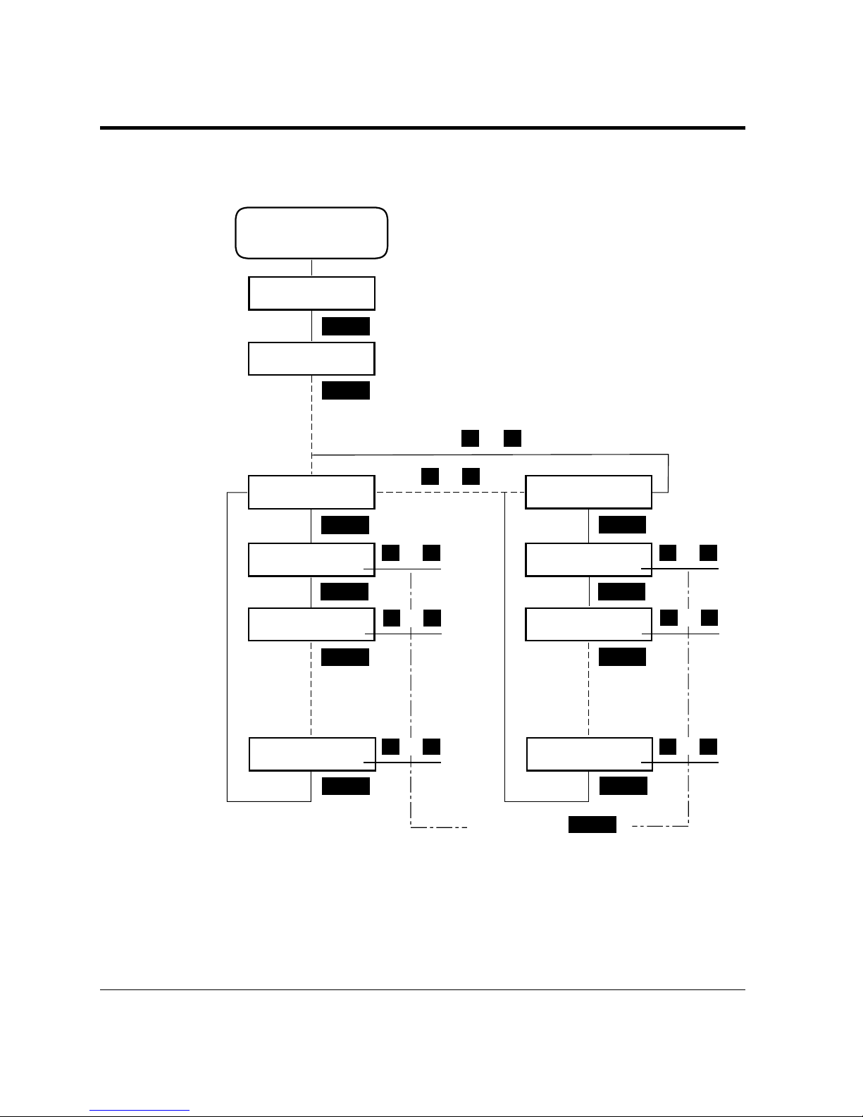
2-30 User’s Manual
➤
➤
➤
ENTER
MENU
➤
➤
➤
MENU
MENU
MENU
+–
➤
➤
+–
➤
➤
➤
+–
➤
➤
➤
➤
➤
MENU
MENU
MENU
+–
➤
➤
+–
➤
➤
➤
+–
➤
➤
➤
➤
➤
+–
–
+
ENTER
ENTER
➤
➤
➤
Enter Menu Mode
and
Select Config menu
SETUP MENU
CONFIG MENU
PERSONALITY
AUTO*
SOFT SWITCH
SW1
SOFT SWITCH
SW4
SOFT SW1-0
OFF*
SOFT SW1-1
OFF*
SOFT SW1-7
OFF*
SOFT SW4-0
OFF*
SOFT SW4-1
OFF*
SOFT SW4-7
OFF*
ON
ON
ON
ON
ON
ON
To decide, press
ENTER
.
or
or
or
or
or
or
or
or
Menu Items
Soft switch setting
Page 78

User’s Manual 2-31
PRINTING AND
PAPER HANDLING
Menu Items
Parallel menu
Acknowledge The pulse width of the ACK signal
Mode1 0.5 µs
Mode2 1.0 µs
Mode3 4.0 µs
Bi-direction Bi-directional Centronics interface mode
NPAP mode Whether the NPAP commands are used.
When using MarkVision™, the NPAP mode
must be Auto or On.
Serial menu
Baud rate Data transfer speed on the serial interface
Pacing Protocol of the serial interface
DTR polarity Level of the DTR signal in the DTR protocol
ROBUST XON ROBUST mode in the Xon/Xoff protocol
Network menu
NPAP mode Whether the NPAP commands are used.
When using MarkVision™, the NPAP mode
must be Auto or On.
BootP Whether the TCP/IP protocol that enables a
workstation to find its IP address is enabled or
disabled for the network adapter
IP address A unique address of the printer in the TCP/IP
network environment
IP netmask Bit mask that logically subdivides the network,
specifying a local network portion of the IP
address
IP gateway A unique address of the equipment for the
gateway to outside of the enclosed
environment
Important:
See the next page for setting IP address, IP netmask, and IP gateway.
Clear warning
<Clear warning> Clearing a consumables life counter (for the
developer unit or the drum unit)
✍
Page 79
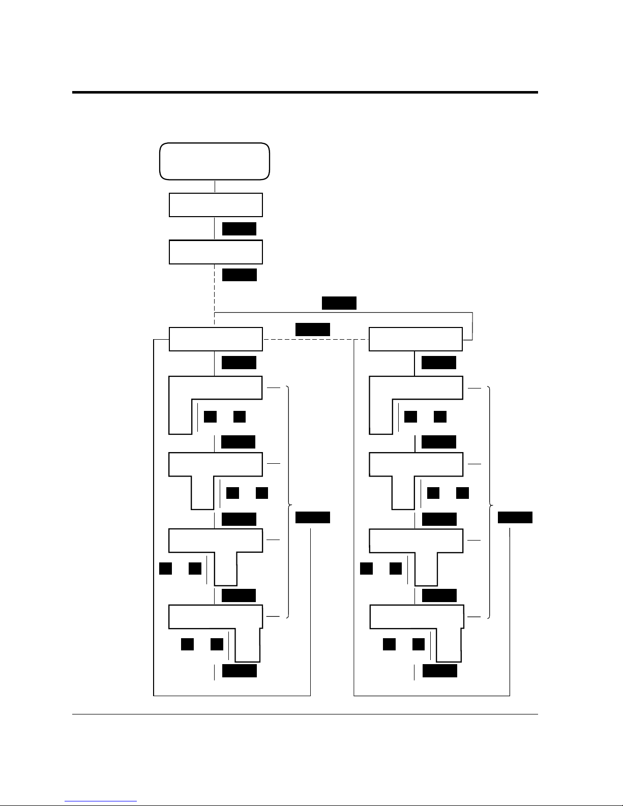
2-32 User’s Manual
Menu Items
Setting IP address, IP netmask, and IP gateway
➤
➤
➤
ENTER
MENU
➤
➤
➤
MENU
MENU
MENU
–
➤
➤
➤
➤
ENTER
ENTER
➤
MENU
MENU
➤
MENU
➤
➤
+
–
➤
➤
+
–
➤
➤
+
–
➤
➤
+
➤
MENU
MENU
MENU
–
➤➤
MENU
➤
➤
+
–
➤
➤
+
–
➤
➤
+
–
➤
➤
+
➤
➤
➤
➤
➤
➤
➤
➤
➤
➤
SETUP MENU
NETWORK MENU
NPAP MODE
AUTO*
IP ADDRESS
133.161.137.201*
or
Enter Menu mode
and
select Network menu
or
or
or
or
or
or
or
To decide,
press
ENTER
.
To decide,
press
ENTER
.
IP ADDRESS
133<161.137.201
134
135
:
:
IP ADDRESS
133.161<137.201
162
163
:
:
IP ADDRESS
133.161.137<201
138
139
:
:
IP ADDRESS
133.161.137.201<
202
203
:
:
IP GATEWAY
133.161.137.200*
IP GATEWAY
133<161.137.200
134
135
:
:
IP GATEWAY
133.161<137.200
162
163
:
:
IP GATEWAY
133.161.137<200
138
139
:
:
IP GATEWAY
133.161.137.200<
201
202
:
:
<: Indicates the preceeding
parameter can be changed.
*: Currently selected value
To the next menu
To the next menu
Page 80

User’s Manual 2-33
PRINTING AND
PAPER HANDLING
Handling Paper
Discusses paper selection and paper handling:
• Types and sizes of paper you can use with this printer, including
envelopes and transparencies
• Ensuring that both the software program and the printer have
compatible paper size settings
• Adjusting the printer for a variety of paper thickness
• Tips on handling print media
• Adjusting the paper tray to fit a different paper size
• Feeding paper manually
Paper Types and Sizes
This printer can print on a variety of common office papers in
addition to standard photocopier bond. Bond paper can range in
basic weight from 60 to 105 g/m
2
(16 to 28 pound) for the paper
tray and from 60 to 199 g/m
2
(16 to 53 pound) for the multifunction feeder (MFF). Smooth paper produces the best print
quality, but textured papers usually provide satisfactory results.
The following descriptions also apply to an optional paper tray.
Caution:
When you use thick paper, follow these guidelines:
• When you are using thick paper, thick envelopes, or special paper
and find improper adhering of toner to the paper, turn the thick
paper mode on using the control panel. This mode is invalid for
transparencies and labels.
• When you cannot be satisfied with the results of the thick paper
mode or want to print on thin paper, use the extension mode of
paper thickness.
• Turn the mode off or reset it to 0 when you print on regular paper.
Printing regular paper with this mode on or set to a value other
than 0 may cause a decrease in print quality or reliability of the
printer.
• With some kinds of paper, curling may happen. In this case, put
the paper face down.
• When printing thick paper of 199 g/m
2
(53 pound), the print
quality may be poor even in thick paper mode, depending on paper
types. We recommend you to make trial printing before using thick
paper. If the print quality is not improved in thick paper mode,
change paper types.
Handling Paper
☞
Page 81
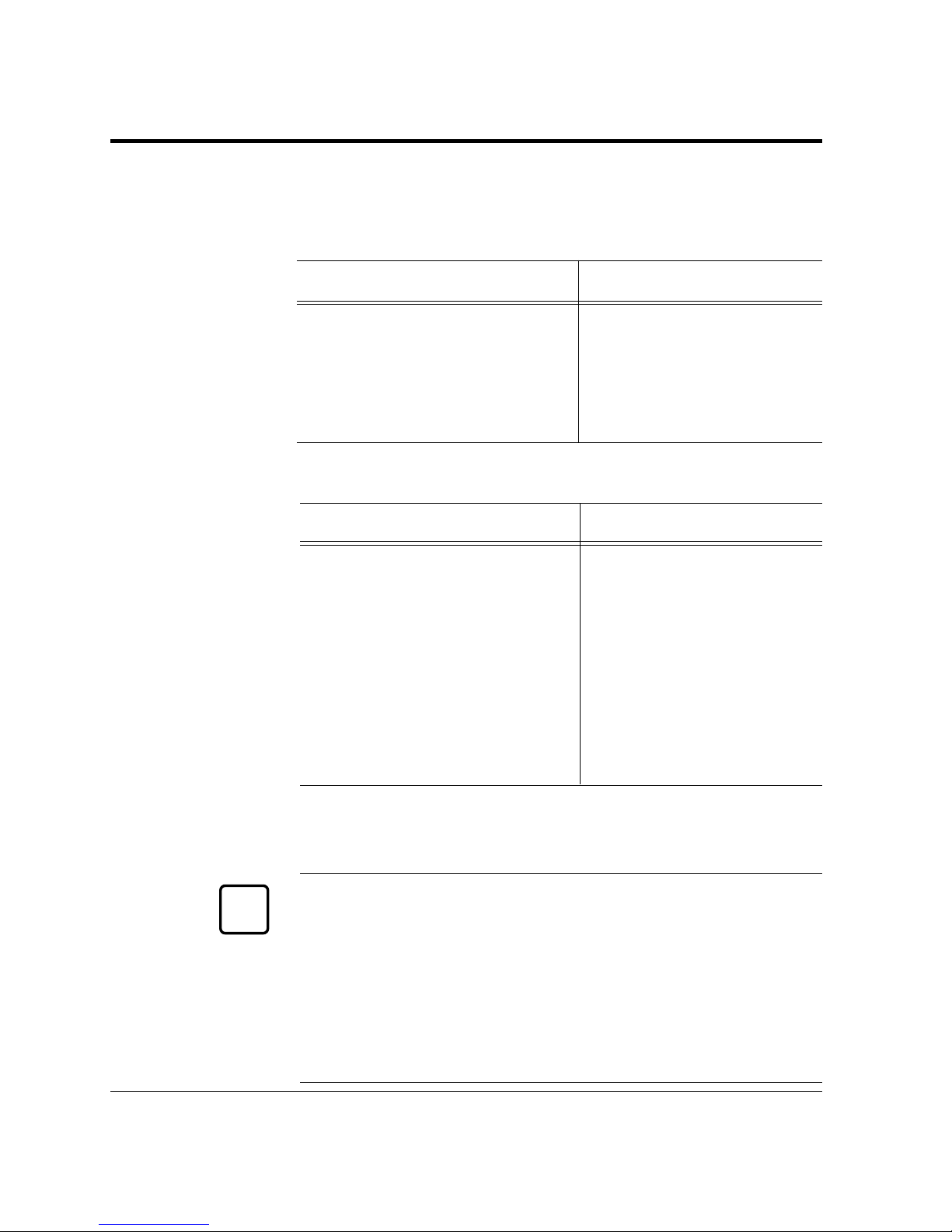
2-34 User’s Manual
Handling Paper
This printer can print on a wide range of paper sizes, but the size is
limited when using paper trays.
• When using a paper tray, the size is:
Paper size (physical) Dimensions
A4 (European letter size) 210 × 297 mm
A5 148 × 210 mm
JIS B5 (Japanese letter size) 182 × 257 mm
Letter (US letter size) 8.5 × 11 in
Legal (US legal size) 8.5 × 14 in
Executive 7.25 × 10.5 in
• When using the MFF, the size is:
Paper size (physical) Dimensions
A4, A5, JIS B5, Letter, Legal, Executive
Same as above
A6 105 ×148 mm
Envelope COM-10 4 1/8 × 9.5 inches
Envelope Monarch 3 7/8 × 7.5 inches
Envelope C5 162 × 229 mm
Envelope DL 110 × 220 mm
Envelope B5 176 × 250 mm
Custom size: Minimum (*) 69 mm wide × 127 mm long
(2.72 × 5 inches)
Maximum 229 mm wide × 356 mm long
(9.01 × 14.01 inches)
* Two-sided printing using an optional duplex unit cannot be done
for A6-size paper, custom-size paper and envelopes. If it is
specified, single-sided printing is automatically done.
Important:
When printing on legal-size paper in the FPS emulation, set the one
of the following:
• Add RAM extension cards of 8M bytes or more (12M bytes or
more in total)
• Select “memory model” in the FPS menu.
If a print job stops halfway with a certain error message printed, the
same measures above often recover the error.
✍
Page 82
User’s Manual 2-35
PRINTING AND
PAPER HANDLING
Handling Paper
Although this printer can print on any sheet within the limits stated
above, printing area and margin calculations are based on several
paper sizes as shown in the table below. Use the control panel to
change the supported paper size.
Paper size (logical) Dimensions Abbreviation
A4 210 × 297 mm A4
A5 148 × 210 mm A5
JIS B5 182 × 257 mm JB5
Letter 8.5 × 11 inches LT
Legal 8.5 × 14 inches LG
Executive 7.25 × 10.5 inches EX
A6 105 × 148 mm A6
Envelope COM-10 4 1/8 × 9.5 inches CO
Envelope Monarch 3 7/8 × 7.5 inches MO
Envelope C5 162 × 229 mm C5
Envelope DL 110 × 220 mm DL
Envelope B5 176 × 250 mm B5
When the PCL emulation is used and if the physical paper size (tray
size or MFF paper size) is different from the logical paper size (value
specified by setup menu of paper size), a paper mismatch error
occurs.
If a paper mismatch error occurs, the printer requests you to load the
correct size of paper on the tray or MFF by the following message:
LOAD MFF XXX or LOAD TRY
n
XXX
XXX means the abbreviation of paper size shown in the third
column of the above table. It is also used in the paper insertion
request message for a paper out error or manual feed mode.
However, you can load the correct size of paper in tray 1 or 2 to
clear the error.
Page 83

2-36 User’s Manual
Adjusting for Paper Thickness
When you are using thin paper, thick paper, or thick envelopes, you
may find improper adhering of toner to the paper, wavy paper, or
light printing. This printer can improve the above print quality
within the paper specifications by means of the thickness control
menu which has two modes, normal and extension. The printer is set
in normal mode as a factory default. To change the mode and select
an option, see Selecting the Thickness Control Menu described
earlier in this chapter.
In normal mode, you can use the thick paper mode, which allows
you to print on thick paper, from 90 to 199 g/m
2
(24 to 53 pound).
The setting is common to all paper sources. The thick paper mode is
automatically used regardless of its option setting when you select an
envelope for MFF paper size.
In extension mode, you can use media modes on tray 1, tray 2 (if
installed), and MFF, which allow you to print on thin paper, thick
paper, or thick envelopes. A different setting can be specified every
paper source. The media mode = 1 (thick paper) is automatically
used when you select an envelope for MFF paper size so long as the
media mode = 0 ( ordinary paper) is being selected.
Caution:
Turn the mode off or reset it to 0 when you print on regular paper.
Printing regular paper with this mode on or set to a value other than
0 may cause a decrease in print quality or reliability of the printer.
Use the following guidelines when printing on thin paper, thick
paper, or thick envelopes:
Basically use the thick paper mode (option: on or off) in the normal
mode:
Off: Ordinary paper
On: Thick paper, 90 to 199 g/m
2
(24 to 53 pound),
Rough surface of paper,
Toner easily scraped off by fingers, or
Printing or back side stained with toner
☞
Handling Paper
Page 84

User’s Manual 2-37
PRINTING AND
PAPER HANDLING
Use a media mode (option: -2 to 5) in the extension mode if you
cannot be satisfied with the normal mode and want to make fine
adjustment. Select an appropriate option as follows:
-2: Thin paper when resulting in waving
-1: Thin paper when resulting in light printing with duplex unit
0: Ordinary paper
1: Thick paper
2: Thick envelope when resulting in toner easily coming off
3: Thick envelope when resulting in light printing
4: Thick rough paper when resulting in smudging
5: Thick rough paper when resulting in light printing
For light printing, see the print quality problems at first. Media
mode for light printing affects only under the limited usage.
With mode number 2, 3, 4, or 5 selected, continuous printing is
allowed up to 30 minutes.
General Tips
Observe the following tips when handling print media.
• Do not use paper that is wrinkled or curled.
• Do not use paper with staples or metal parts.
• When printing both sides of sheets and your printer is a
PrintPartner 12MX, we recommend you to use an optional duplex
unit. If your printer is PrintPartner 12M, use the MFF (in this case,
remove curls after first printing). Use paper in 60 to 105 g/m
2
(16
to 28 pound) weight for the duplex unit and 60 to 199 g/m
2
(16 to
53 pound) weight for the MFF. Paper thinner than this weight may
be wrinkled thus causing decrease in print quality.
• Two-sided printing is not allowed for transparencies, envelopes,
and labels even if your printer has the duplex unit.
Handling Paper
Page 85
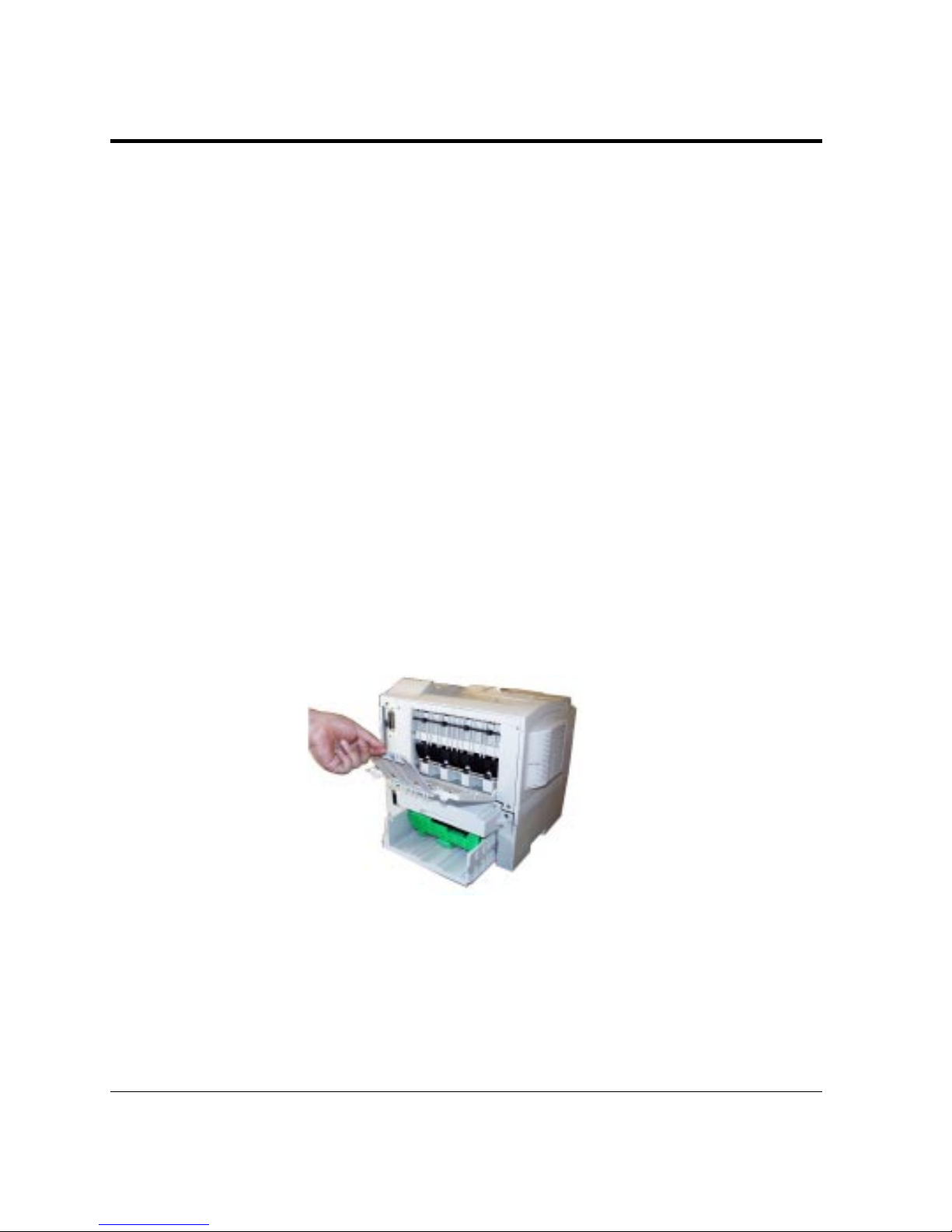
2-38 User’s Manual
Handling Paper
Preprinted Sheets
In general, you can safely print on preprinted sheets such as
letterhead. However, letterhead with thermographic (raised)
printing, embossing, or foil stamping may not work well. The forces
used to create these effects (heat and/or pressure) are also used in the
printer’s fuser unit. For this reason, the fuser unit may damage the
preprinted image.
Load preprinted paper with the printed side facing down in the
paper tray. When using the MFF, place paper with the printed side
facing up. For printing in portrait orientation, the letterhead should
be at the front of the tray. For landscape orientation, it should be at
the right of the tray. For more information on printing in different
orientations, see the later section of this chapter.
Transparencies
This printer can print on overhead transparency material.
• We recommend you to set up the rear stacker so that transparencies
are ejected straight out the back to minimize curl.
The capacity of the rear stacker is about 20 sheets.
• Use materials specially designed for laser printers or photocopiers.
Transparencies must be proof against 205°C (401°F), the
maximum temperature of the heat roller.
• Always feed transparency material from the multi-function feeder
(MFF).
Page 86

User’s Manual 2-39
PRINTING AND
PAPER HANDLING
Handling Paper
• To remove curls from printed transparency materials, use correct
frames or put a weight on them until they lay flat.
• Be sure to fan the transparency stack to prevent sheets from
sticking together.
Envelopes
This printer prints well on envelopes if you carefully follow these
guidelines:
• Use envelopes made of paper in 105 g/m
2
(28 pound) or less
weight. Printing with envelopes made of paper thinner than this
weight may produce wrinkles thus causing decrease in print quality.
• Be sure to set up the rear stacker so that envelopes are ejected
straight out the back to minimize curl.
The capacity of the rear stacker is about 20 sheets.
• Use the envelope sizes shown in the preceding table.
• To avoid damage to the printer, never use envelopes with clasps,
snaps, windows, or synthetic materials.
• Feed from the multi-function feeder (MFF) of the printer.
• Feed the envelopes with the gummed side of the flaps facing
downward.
• Do not use “encapsulated” adhesives, which seal by pressure alone.
• To avoid jamming, restrict the minimum paper weight to 64 g/m
2
(17 pound).
• To avoid creasing along the edges, use high-quality envelopes with
stiff edges.
• To avoid uneven printing, do not attempt to print on the gummed
overlap areas.
• Be sure to feed or load the envelopes with the envelope centered
against the MFF, using the paper guides.
• Before attempting large-scale printing on envelopes, consult with
your stationery dealer. Also, test the envelopes carefully for
consistent, trouble-free printing.
• If fusing is insufficient (toner is easily scraped off by fingers), use
the thick paper mode.
Page 87
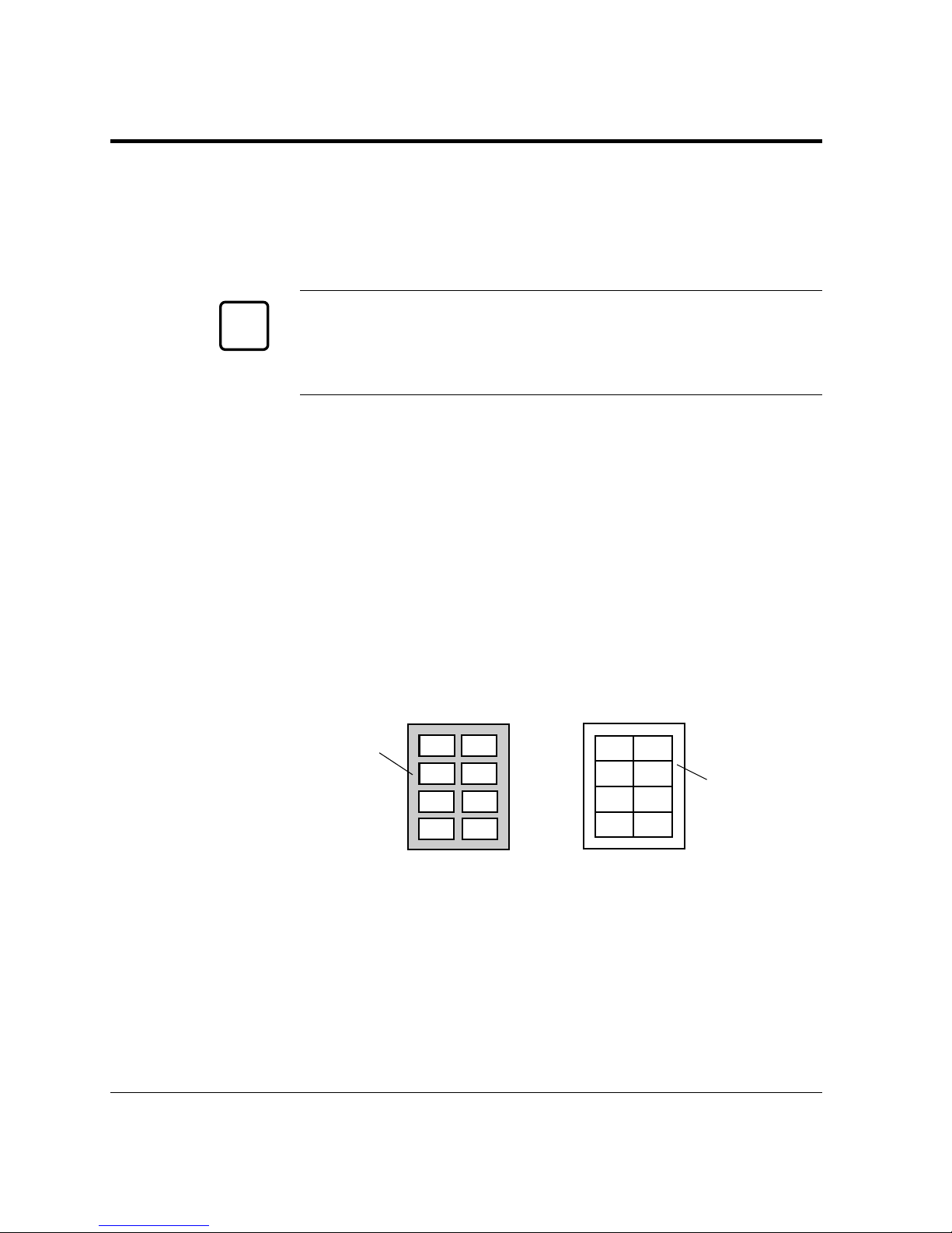
2-40 User’s Manual
• Moist envelopes are liable to wrinkle.
• When printing envelopes on which adhesive tape is used, use those
which resist the temperature and pressure in the fuser unit.
• Do not use envelopes for double-sided printing.
Caution:
Never use envelopes which are coated inside or those on which
adhesive portions are exposed. These types of envelopes may generate
harmful gas at high temperature.
Labels
This printer prints well on labels if you carefully follow these guidelines:
• Be careful to use labels under normal operating conditions. Labels
are sensitive to temperature and humidity.
• Use the rear stacker so that labels are ejected straight out the back
to minimize curl.
• Use only labels without backing sheets exposed in the printable
area. Labels mounted separately on a backing sheet tend to slip,
resulting in crocked print.
Handling Paper
Acceptable
Backing sheet
is not exposed.
Not acceptable
Backing
sheet is
exposed.
☞
• Test-print labels before using them. If jamming problems occur
and continue, try a different type of label.
• Use labels whose adhesive is proof against 205°C (401°F), the
maximum temperature of the heat roller.
• Do not use labels for double-sided printing.
Page 88
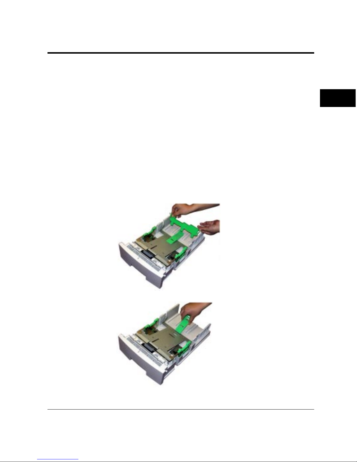
User’s Manual 2-41
PRINTING AND
PAPER HANDLING
Handling Paper
Changing the Paper Tray Size
The paper tray can be adjusted to one of the six paper sizes: A4, A5,
B5 (JIS B5), LTR (Letter), LGL (Legal), and EXE (Executive). To
change the size, follow these steps:
1. Remove the paper tray
from the printer.
Refer to the illustration for
the parts you adjust when
changing the size of the
tray.
2. Remove the rear paper
guide from the tray. Push
the two catches inward to
release the pins from the
holes and remove the rear
paper guide from the tray.
3. If you want to use the legal
size, move the center guide
one slot outwards. Lift the
rear end of the center guide
to detach it from the
pressure plate. Then, put
the front end of the center
guide into the adjacent slot.
Page 89
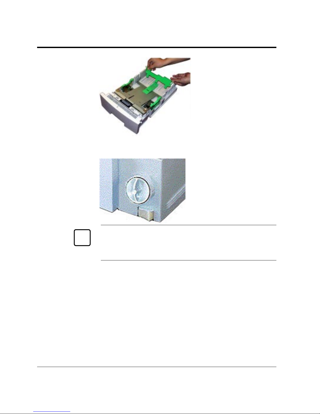
2-42 User’s Manual
Handling Paper
✍
4. Attach the rear paper guide
to the correct position.
Refer to the engraving on a
side guide to locate the
notch of the desired paper
size.
First push the bottom
center tab of the rear paper
guide into the notch, then
push the two catches inward
to put the two pins into the
corresponding side holes.
5. Change the setting of the
paper size dial. Turn the
dial to the correct position.
Important:
Set the paper size dial to the size of the loaded paper and select the
correct paper size on the print menu of your application program, or
a paper mismatch error will occur when printing.
6. Load paper and check that
the paper fits the tray.
Adjust the right side-guide
so that both side-guides fit
to the width of paper
snugly. Put the paper stack
under the paper holders.
7. Return the paper tray. Slide
the tray back into the
printer.
071
Page 90
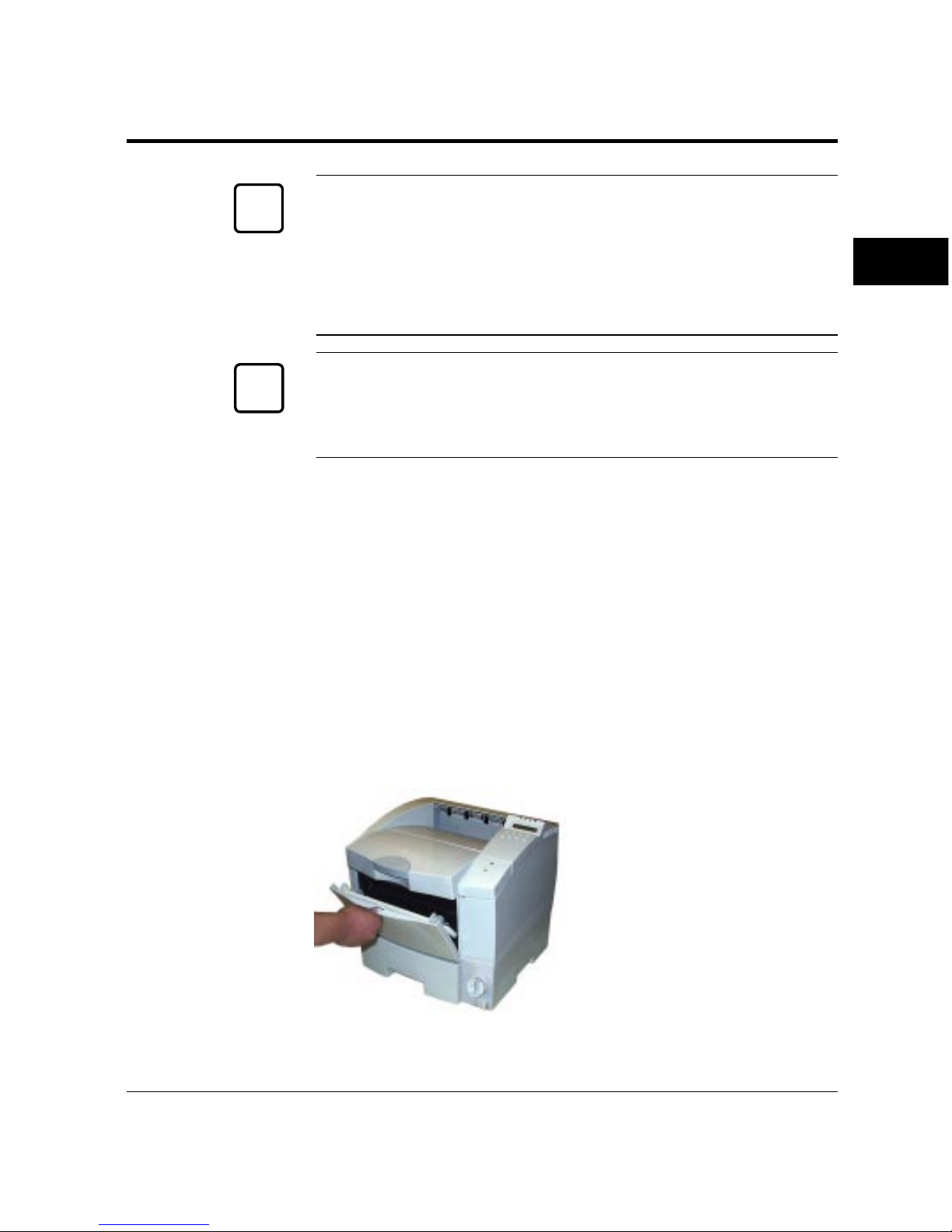
User’s Manual 2-43
PRINTING AND
PAPER HANDLING
Handling Paper
Caution:
Put the paper stack in the tray with the printing side faced down.
If paper is wavy or curled, remove waved or curled sheets of paper.
If paper is abnormally curled or becomes cylindrical after printing,
use the paper upside down. It may reduce a degree of curl.
Important:
Do not turn the paper size dial after you have loaded paper.
Changing the dial setting causes a paper mismatch error when
printing the paper.
Using the Multi-function Feeder (MFF)
This printer has a multi-function feeder (MFF), accessible with the
front door opened, to allow you to handle a stack of many types of
sheets. Use the MFF for printing, thick paper, envelopes, overhead
transparencies, and labels.
The MFF also allows you to feed a sheet manually in manual feed
mode. This mode is useful to print a document on a different type of
paper without unloading your regular paper from the paper tray.
MFF not in Manual Feed Mode
1. Open the front door. Pull
the depression at the top of
the front door.
☞
✍
Page 91
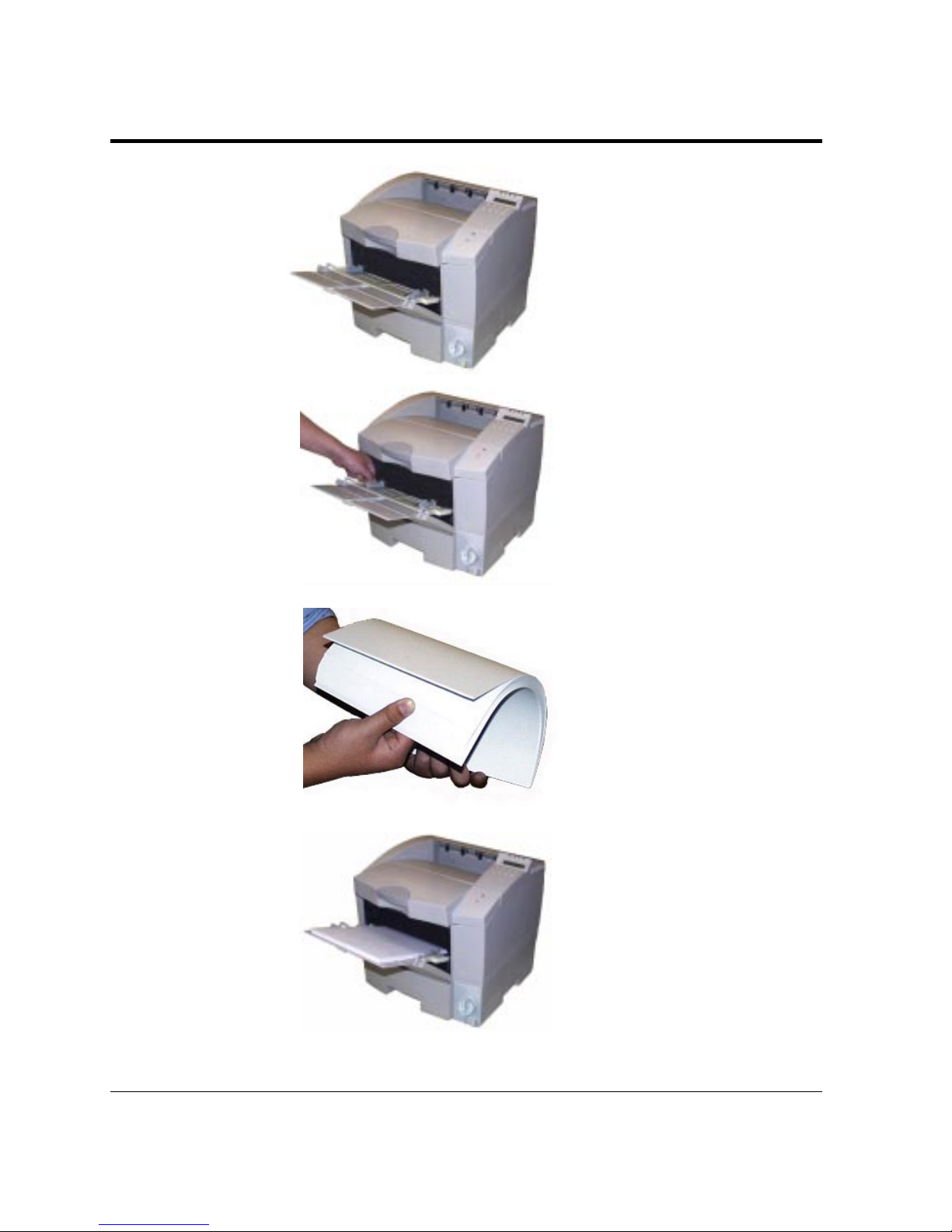
2-44 User’s Manual
Handling Paper
2. Extend the paper support.
Pull the center top of the
paper support all the way.
3. Adjust the paper guides.
Slide the paper guides to fit
the width of paper snugly.
4. Fan the paper stack. When
loading paper, be sure to
fan the paper stack to
prevent sheets from sticking
together.
5. Load paper. Place the paper
stack on the MFF and push
it all the way until its front
portion is stopped.
Page 92
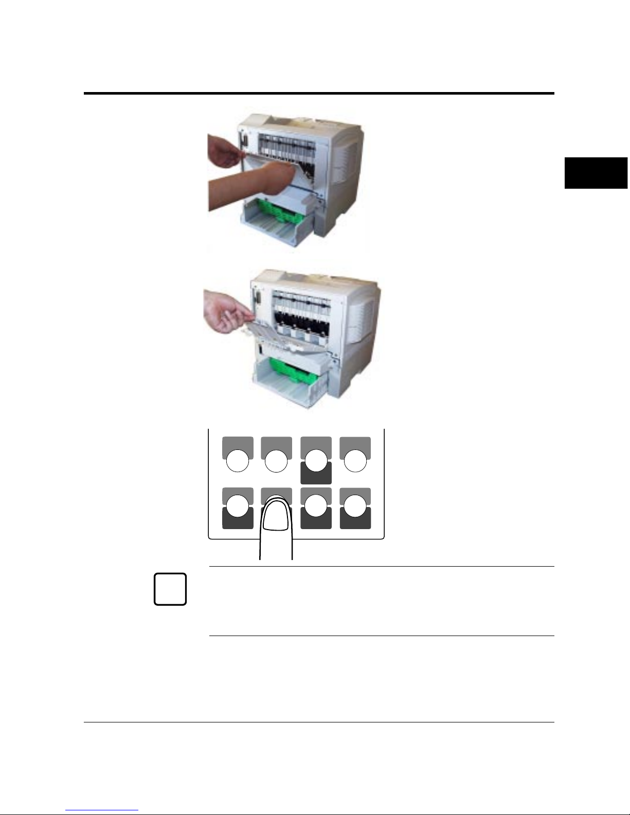
User’s Manual 2-45
PRINTING AND
PAPER HANDLING
MFF
PAPER SIZE
PRINT
FONT
SELF
TEST
RESET
CONT.
ENTER
–
+
MENUREADY
FORM
FEED
RESET
MENU
SELECT
6. Open the rear stacker. If
necessary, open the rear
stacker.
7. Extend the subguide. Raise
the top of the subguide to
open it.
8. Set the physical paper size
of the MFF. Use the MFF
paper size menu to select
the size of paper loaded in
the MFF. See the early
section, Setting MFF Paper
Size, in this chapter.
Important:
The MFF has two operation modes: First mode and Cassette mode.
When using it in Cassette mode (default), you must specify the
physical paper size of the MFF.
Handling Paper
✍
Page 93
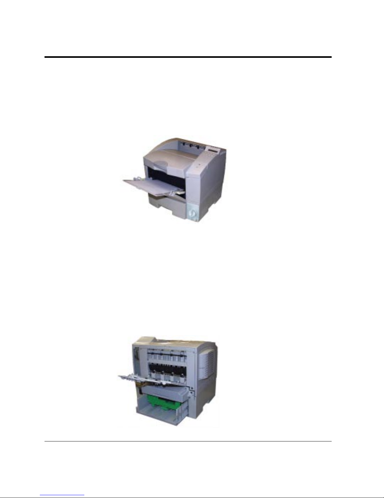
2-46 User’s Manual
MFF in Manual Feed Mode
To use the MFF in manual feed mode, first select MANUALFEED ON
using the tray select mode of the control panel. Next, start your
software program to print a file. Paper handling is similar to that of
the multi-function feeder. The following shows paper loading step
only:
Place a sheet with print
side face up. When the
printer is ready to print, it
displays the message
Insert
size
to prompt
you to prepare a sheet of
paper. Insert the sheet until
it is stopped. Insufficient
insertion prevents paper
from being fed or causes
skewed feeding.
If your file has additional pages, the printer prompts you for another
sheet.
Setting Up the Rear Stacker
This printer has a rear stacker that allows you to eject sheets straight
out the back to minimize curl. Use the rear stacker to print thick
paper, envelopes, overhead transparencies, and labels.
To use the rear stacker, follow these steps:
1. Open the rear stacker. Pull
the projections at the top of
the stacker.
2. Extend the subguide. Raise
the top of the subguide to
open it.
Handling Paper
Page 94
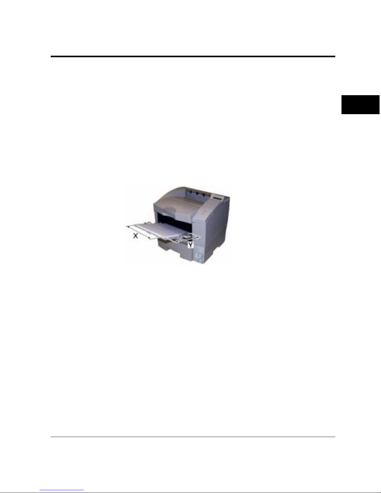
User’s Manual 2-47
PRINTING AND
PAPER HANDLING
Printing on Custom-Sized Paper
This printert can print on custom-sized paper (nonstandard size
paper) by using the multi-function feeder (MFF).
Note that you can also use the MFF in manual feed mode to print
custom-sized paper. You must load sheets one by one and the printer
does not check the paper size.
To print on custom-sized paper, follow these steps:
1. Specify the size of paper to be used. Set the printer in menu
mode using the control panel and select the Page Format menu.
a. Select Custom for Paper/
Envelope.
b. Adjust Custom X and
Custom Y to the size of
paper to be used.
To the paper feed direction,
length X is perpendicular
and length Y is parallel as
shown left.
When you specify the paper size from the printer driver, use a
property sheet screen.
2. Specify the physical paper size of the MFF. When the MFF
mode is “Cassette” (default), select the MFF Paper Size menu
from the control panel and select “Custom” in the menu. When
the MFF mode is “First”, you do not need to specify the paper
size.
Handling Paper
Page 95
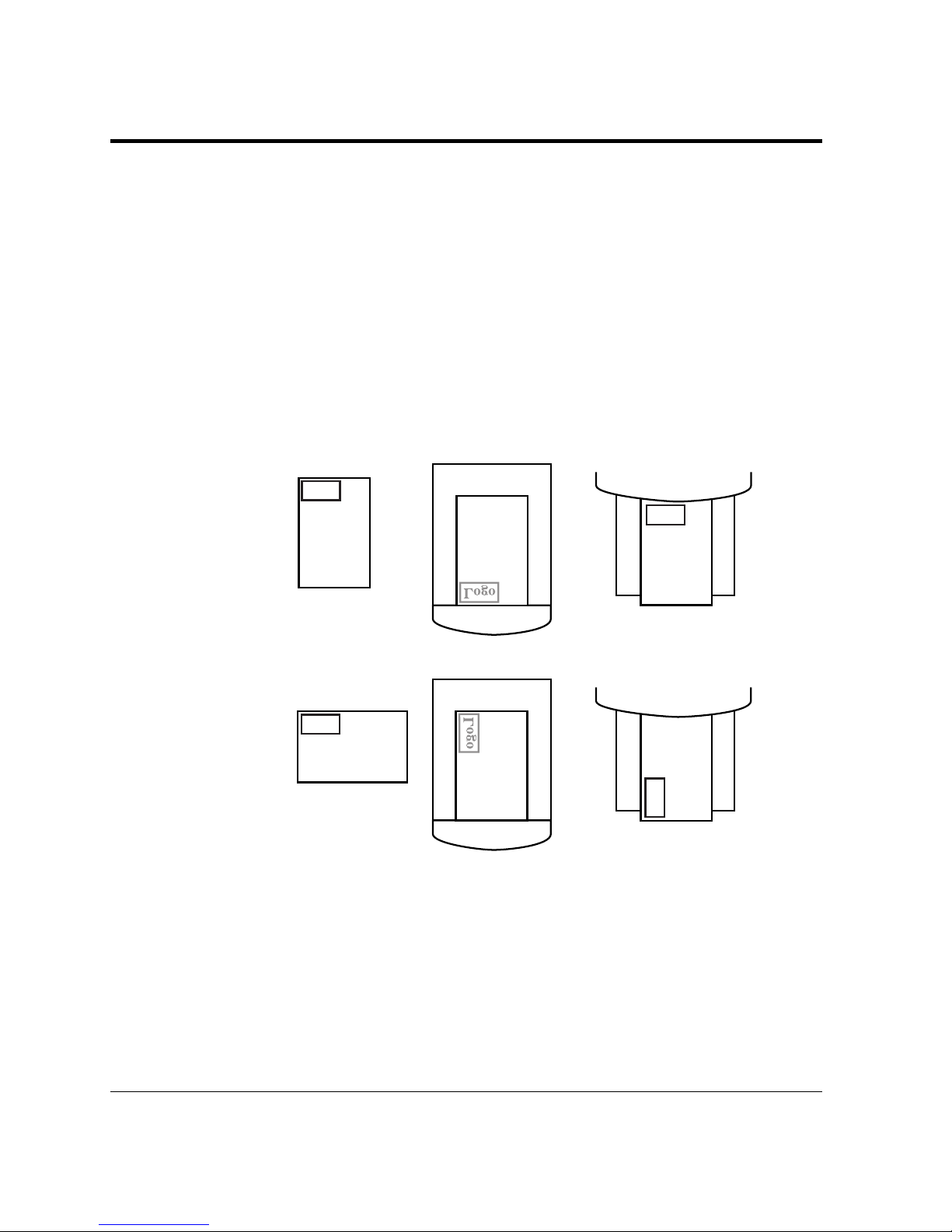
2-48 User’s Manual
Handling Paper
Logo
Logo
Logo
Logo
Portrait
Landscape
Tray
Tray
Page Orientation
When you want to print on preprinted paper like letterhead, it is
important to understand the relationship between the paper loading
direction (lengthwise feeding only) and the page orientation
(portrait/landscape).
When using a paper tray, place the paper with its letterhead facing
down. Insert the paper as shown below.
When using the MFF, place the paper with its letterhead facing up.
Insert the paper as shown below.
Figure 2–4 Loading letterhead in a paper tray or on the MFF
MFF
MFF
Page 96
User’s Manual 3-1
ENHANCING &
CUSTOMIZING
3
CHAPTER
Enhancing and Customizing the Printer
This chapter explains the following ways to enhance or customize
your printer:
• Add RAM up to a total of 64 megabytes except the resident RAM.
• Add an alternate emulation to the resident one.
• Add an additional interface to the parallel and/or serial interfaces.
• Add a paper feeder as the second paper source.
• Add a duplex unit as the two-sided printing mechanism (available
for 12MX only).
You can order these options separately. See Appendix B for ordering
information. Contact your dealer for information on other new
options that may be available.
The following gives you brief information and installation
instructions for each option.
Caution:
Be sure that the printer is turned off before installing an option.
Do not touch any connector contacts to avoid possible electrostatic
damage to the printer.
You may need to expand RAM to process more data for either of the
following reasons:
• You commonly download several fonts when printing a job
• You print files with complex graphics
• In FPS emulation (standard for 12MX and option for 12M), the
requirement for the total capacity of memory is as follows:
- For printing legal-size paper at 600 dpi: 12M bytes or more
- For printing at 1200 dpi: 16M bytes or more
Adding RAM
☞
Page 97
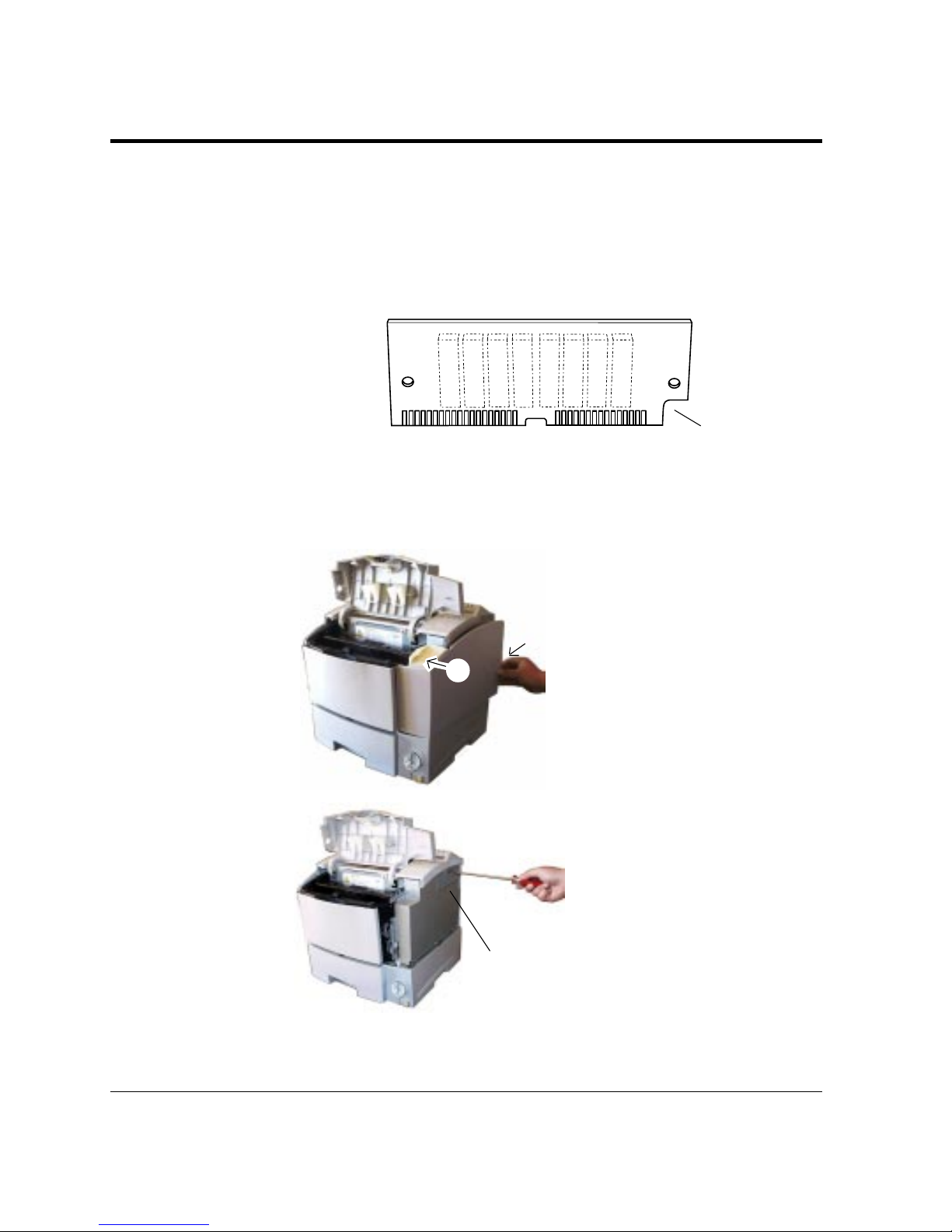
3-2 User’s Manual
To install the RAM card, first make sure the printer is turned off and
follow these steps:
1. Open the upper door and
remove the right side
cover of the printer. To
remove the right side cover,
remove screws ① and ≠ and
open the rear ➂ of the cover
while pulling it backwards.
You will see a connector
cover on the metal plate.
2. Remove the connector
cover. Remove the fastening
screw and the cover. You
can now see three
connectors (upper two ivory
ones for RAM cards).
You can install two memory expansion cards. The expansion card
can have 4, 8, 16, or 32 megabytes of RAM. Together with the
printer’s resident memory (4 megabytes for 12M and 8 megabytes
for 12MX), these expansion options offer a range of RAM from 4 to
68 (12M) or 72 (12MX) megabytes.
Adding RAM
Insert with cut
facing down and
to the right
(8MB card)
Connector
cover
①
≠
➂
Page 98
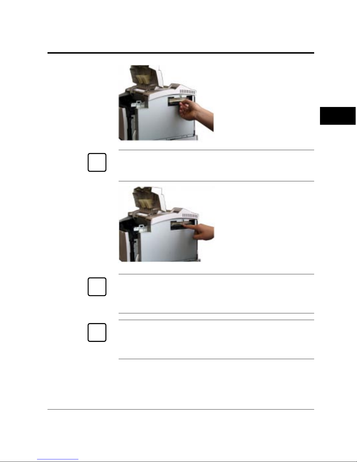
User’s Manual 3-3
ENHANCING &
CUSTOMIZING
3. Orient the RAM card.
Hold the card with the cut
corner down and facing
right and insert the card
aslant into connector.
Caution:
Do not touch any connector contacts to avoid possible electrostatic
damage to the printer.
4. Install the RAM card.
Push its top edge
downwards so that holes of
the card align with locating
pins of the connector and
the card is secured by
retaining clips.
Caution:
The expansion RAM card or font card is easily damaged by static
electricity. Hold it by its edges and do not touch the electric circuit
parts and wiring.
Important:
When installing two RAM cards, first install the lower one, and then
the upper one. If you install them in the opposite order, the upper
card prevents the lower card from being installed.
Adding RAM
✍
☞
Use upper two
ivory connectors
☞
Page 99
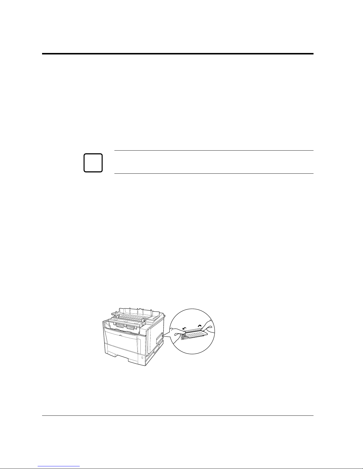
3-4 User’s Manual
Adding RAM
5. Secure the connector cover.
Secure the connector cover,
which was removed in step
2, with a screw.
Caution:
Be sure to secure the connector cover to avoid a fire hazard.
6. Close the side cover and
then upper door.
Turn power on. If necessary, change buffer memory assignment
(page protect or jam recovery) using the control panel.
Removal
To remove a RAM card
push out the retaining clips.
when the card slants
outwards, pull the card to
remove.
☞
Page 100
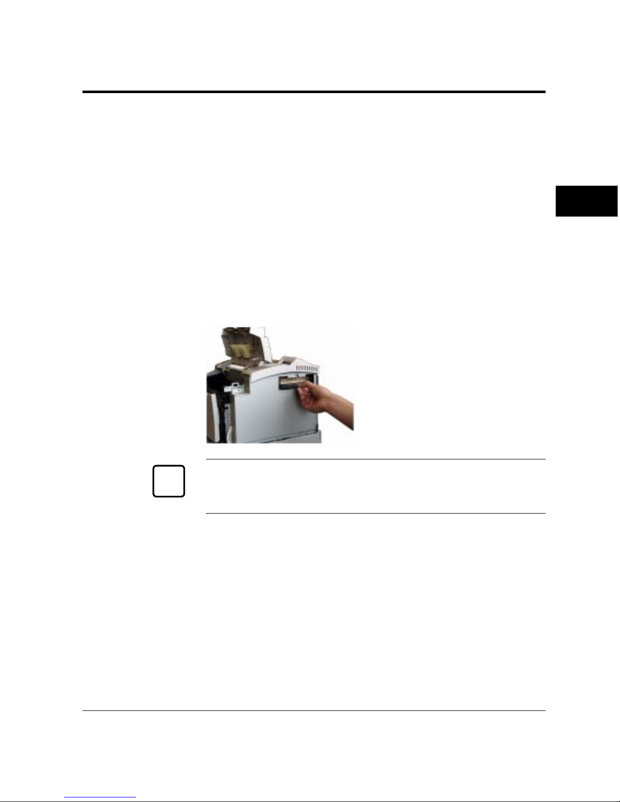
User’s Manual 3-5
ENHANCING &
CUSTOMIZING
Alternate emulations are offered with emulation cards. You can use
these emulations to connect your printer to different computers. The
FPS card (PostScript Level 2 compatible) is available. Note that the
FPS emulation is standard for 12MX.
The installation procedure is the same as that for the RAM card
except that the emulation card uses the bottom connector.
To install the FPS emulation card, follow these steps:
1. If RAM cards are already installed, remove them.
2. Insert the emulation card into the bottom black connector.
3. Reinstall the RAM cards.
Installing an Alternate Emulation
Caution:
After installing cards, be sure to secure the connector cover to avoid a
fire hazard. See the previous section for RAM cards.
With default settings, the printer automatically selects the active
emulation. To specify an emulation steadily, select the emulation
using the control panel. Use the Personality item of the Config
menu.
Once you change the emulation, the other menus change to reflect
the options and functions of the new emulation. Procedures for
working in the menus remain the same as for the PCL emulation.
Use the bottom
black connector
Installing an
Alternate
Emulation
☞
 Loading...