

Page 1
PRIMERGY 300 - Server
systems
Operating Manual
Page 2

Is there ...
... any technical problem or other
question you need clarified?
Please contact:
• one of our IT Service Shops
• your sales partner
• your sales office
The addresses of your service partners
are contained in the guarantee booklet
or in the service address booklet.
The latest information on our products,
tips, updates, etc., can be found on the
Internet under:
http://www.siemens.com/pc
... anything you want to tell us
about this manual?
Please send us your comments quoting
the order number of the manual.
Siemens AG
Redaktion OEC BS2 OS ID 4
Otto-Hahn-Ring 6
D-81730 München
Page 3

Page 4
Dieses Handbuch wurde auf Recycling-Papier gedruckt.
This manual has been printed on recycled paper.
Ce manuel est imprimé sur du papier recyclé.
Este manual ha sido impreso sobre papel reciclado.
Questo manuale è stato stampato su carta da riciclaggio.
Denna handbok är tryckt på recyclingpapper.
Dit handboek werd op recycling-papier gedrukt.
Herausgegeben von/Published by
Siemens AG
D-81730 München
Bestell-Nr./Order No.: A26361-K423-Z202-3-7619
Printed in the Federal Republic of Germany
AG 1198 11/98
A26361-K423-Z202-3-7619
A26361-K423-Z202-3-7619A26361-K423-Z202-3-7619
A26361-K423-Z202-1-7619
Page 5
Introduction
Important Notes
PRIMERGY 300 - Server
systems
Operating Manual
Preparation for use and
operation
Settings in BIOS Setup
Propertyand data
protection
Troubleshooting
and tips
System expansions
Technical data
November 1998 edition
Index
Page 6

Your training needs?
The Siemens Training Centers offer you a wide range of training courses in
information technology and on IT products and other subjects - onsite near to your
workplace or offsite at one of our training centers.
Contact us for information on consulting, course schedules and selfstudy material Either fax (which is the fastest way):
Fax: ..49 89 636-42945
Or write to:
Siemens AG
Training Center, Beratungsservice
D-81730 München
Intel and Pentium are registered trademarks of Intel Corporation, USA.
Copyright ã Siemens AG 1997.
All rights, including rights of translation, reproduction by printing, copying or similar methods,
even of parts are reserved.
Offenders will be liable for damages.
All rights, including rights created by patent grant or registration of a utility model or design,
are reserved.
Delivery subject to availability. Right of technical modification reserved.
Page 7

Contents
Introduction ........................................................................................................... 1
Notational conventions............................................................................................ 2
Important Notes.....................................................................................................3
Safety...................................................................................................................... 3
Manufacturer’s notes...............................................................................................6
Transporting the server.................................................................................... 6
CE certificate....................................................................................................6
Disposal and recycling ..................................................................................... 6
FCC Class A Compliance Statement ...................................................................... 7
Important notice concerning power cord selection .................................................. 8
For the United States and Canada...................................................................8
For the United Kingdom ................................................................................. 10
Preparation for use and operation.....................................................................11
Unpacking and checking the delivery.................................................................... 11
Preparing the PC for use.......................................................................................12
Setting up the server ............................................................................................. 12
Connecting external devices ................................................................................. 13
Ports for external devices............................................................................... 14
Connecting the keyboard ............................................................................... 14
Connecting the mouse ................................................................................... 15
Connecting devices with serial or parallel port ............................................... 15
Connecting the monitor.................................................................................. 15
Connecting the monitor to the power voltage........................................................ 16
Connecting the server to the power voltage.......................................................... 17
Unlocking/locking the server.................................................................................. 18
Switching the server on and off ............................................................................. 19
Displays on the server........................................................................................... 20
Switching on for the first time ................................................................................ 21
ServerStart..................................................................................................... 21
Saving the EISA configuration........................................................................ 22
ICU utility........................................................................................................ 23
Configuring the Disk Array Controller (EISA) ................................................. 23
Configuring the Disk Array Controller (PCI) ................................................... 25
Configuring the standard SCSI controller....................................................... 26
Configuring the onboard SCSI controller........................................................ 26
Installing the operating system....................................................................... 26
Working with floppy disks and CD-ROMs..............................................................27
Cleaning the server ............................................................................................... 27
A26361-K423-Z202-3-7619
Page 8

Contents
Settings in BIOS Setup........................................................................................29
Calling BIOS Setup................................................................................................29
Operating BIOS Setup...........................................................................................31
Exiting BIOS Setup................................................................................................32
Property and data protection..............................................................................33
BIOS Setup security functions...............................................................................33
Setting the Setup password............................................................................35
Setting the System password .........................................................................37
Troubleshooting and tips....................................................................................39
Power-on display remains dark after you have switched on your server ...............39
The screen stays blank..........................................................................................40
Flickering stripes on the monitor screen ................................................................41
No screen display or display drifts .........................................................................41
No mouse pointer displayed on the screen............................................................41
The floppy disk cannot be read or written..............................................................42
Time and/or date is not correct ..............................................................................42
The system cannot be started up...........................................................................43
Error messages on the screen...............................................................................45
System expansions .............................................................................................47
Opening the server ................................................................................................47
Assembling the server ...........................................................................................51
Installing and removing drives ...............................................................................54
Installing or removing the hard disk drive .......................................................55
Installing an accessible drive..........................................................................61
Removing an accessible drive........................................................................63
Changing the floppy disk drive........................................................................65
Installing and removing boards..............................................................................69
Installing a board ............................................................................................69
Removing a board ..........................................................................................71
Installing the RTDS hard disk drive........................................................................72
Extensions on the system board............................................................................73
Technical data......................................................................................................75
Index .....................................................................................................................77
A26361-K423-Z202-3-7619
Page 9

Introduction
Your PRIMERGY server is based on the latest Intel processor technology and has
space for installing four accessible drives (three 5 1/4 inch drives and one 3 1/2
inch drive) and either five non-accessible 3 1/2 inch drives of one inch height or
three of 1.6 inch height.
Of course, your PRIMERGY server has plug-and-play capability. It automatically
recognizes and installs boards, devices and drives that support this capability. If
however you want to make system settings by hand, you can do so in the easy-touse BIOS Setup.
Security functions in the BIOS Setup and on the system board protect the data on
the server against manipulation. Additional protection is offered by the lockable
server door and an anti-theft facility.
This Operating Manual tells you how to put your server into operation and how to
operate it in daily use.
Further information on this server is provided:
• in the manual „Safety and ergonomics“
• in the Operating Manual for the monitor
• in the Technical Manual for the system board
• in the documentation of your operating system
• in the information files of your operating system (e. g. *.TXT or *.HLP)
• in the Operating Manual of Server Management and Remote TDS
• in the documentation for the boards and drives
A26361-K423-Z202-3-7619 1
Page 10
Introduction Notational conventions
Notational conventions
The meanings of the symbols and fonts used in this manual are as follows:
Pay particular attention to texts marked with this symbol. Failure to
!
observe this warning endangers your life, destroys the system, or may
lead to loss of data.
This symbol is followed by supplementary information, remarks and tips.
i
Ê Texts which follow this symbol describe activities that must be performed.
Ë This symbol means that you must enter a blank space at this point.
Ú
Ú This symbol means that you must press the Enter key.
ÚÚ
Texts in this typeface are screen outputs from the system.
Texts in this bold typeface are the entries you make via the keyboard.
Texts in italics indicate commands or menu item.
"Quotation marks" indicate names of chapters and terms that are being
emphasized.
2 A26361-K423-Z202-3-7619
Page 11
Important Notes
In this chapter you will find information regarding safety which it is essential to take
note of when working with your server. The manufacturer's notes contain helpful
information on your server.
Safety
Pay attention to the information provided in the manual "Safety and
!
ergonomics".
• During installation and before operating the device, observe the instructions
on environmental conditions in the chapter entitled "Technical data" as well as
the instructions in the chapter "Preparation for use and operation".
• Please check whether the workstation is set to the local power supply (see
chapter "Preparation for use and operation").
• The main switch and the ON/OFF switch do not disconnect the server from the
line voltage. To disconnect the line voltage completely, remove the power plug
from the grounded power outlet.
• When cleaning the server observe the relevant notes in the chapter
"Preparation for use and operation".
• When connecting and disconnecting cables, observe the relevant notes in the
chapter „Preparation for use and operation“.
• Replace the lithium battery on the system board in accordance with the
instructions in the Technical Manual for the system board.
• The CD-ROM drive contains a light-emitting diode (LED), classified according
to IEC 825-1:1993:LASER CLASS 1.
• Keep this Operating Manual together with your device. If you pass on the
device to third parties, you should also pass on the Operating Manual.
Warning
The lithium battery of the device may only be replaced by one that is
identical or by a type recommended by the vendor. If the lithium battery
!
is not replaced in the proper manner, there is a danger of explosion (see
the Operating Manual for your device).
A26361-K423-Z202-3-7619 3
Page 12
Important Notes Safety
VARNING
Explosionsfara vid felaktigt batteribyte. Använd samma batterityp eller en
ekvivalent typ som rekommenderas av apparattillverkarenfabrikanten.
!
Kassera använt batteri enligt fabrikantens instruktion.
ADVARSEL
Lithiumbatteri - Eksplosionsfare ved fejlagtig håndtering. Udskiftning må
kun ske med batteri af samme fabrikat og type. Lever det brugte batteri
!
tilbage til leverandøren.
ADVARSEL
Eksplosjonsfare ved feilaktig skifte av batteri. Benytt samme batteritype
eller en tilsvarende type anbefalt av apparatfabrikanten. Brukte batterier
!
kasseres i henhold til fabrikantens instruksjoner.
VAROITUS
Paristo voi räjähtää, jos se on virheellisesti asennettu. Vaihda paristo
ainoastaan laitevalmistajan suosittelemaan tyyppiin. Hävitä käytetty
!
paristo valmistajan ohjeiden mukaisesti.
Note on the laser
If your device is equipped with a CD-ROM drive, the following condition applies:
The CD-ROM drive contains a light-emitting diode (LED), classified according to
IEC 825-1:1993:LASER CLASS 1; it must not be opened.
Laserhänvisning
Om din apparat är utrustad med en CD-ROM-enhet gäller följande:
CD-ROM-enheten innhåller en ljusemitterande diod (LED), klassificerad enligt IEC
825-1:1993: KLASS 1 LASER APPARAT, och får därför inte öppnas.
Laserinformation
Skal enheden forsynes med et CD-ROM drev gælder følgende:
CD-ROM drevet indeholder en lysdiode (LED), klassificering iflg. IEC 8251:1993:LASER KLASSE 1 og må derfor ikke åbnes.
4 A26361-K423-Z202-3-7619
Page 13
Safety Important Notes
Laserinformation
Følgende gjelder hvis maskinen er utstyrt med en CD-ROM stasjon:
CD-ROM stasjonen inneholder en lysutviklende diode (LED), som er klassifisert
etter IEC 825-1:1993:LASER KLASSE 1, og skal derfor ikke åpnes.
Laser-ohje
Jos laitteeseen on kytketty CD-ROM-asema:
CD-ROM-asema sisältää valoa säteilevän diodin (LED), joka on luokiteltu
määräyksen IEC 825-1:1993:LASER LUOKKA 1 mukaisesti. Tämän vuoksi
asemaa ei saa avata.
Modules with electrostatic sensitive devices (ESD) may be identified by labels.
When you handle modules fitted with ESDs, you must observe the following points
under all circumstances:
• You must always discharge yourself (e.g. by touching a grounded object)
before working.
• The equipment and tools you use must be free of static charges.
• Pull out the power plug before inserting or pulling out modules containing
ESDs.
• Always hold modules with ESDs by their edges.
Never touch pins or conductors on modules fitted with ESDs.
A26361-K423-Z202-3-7619 5
Page 14
Important Notes Manufacturer's notes
Manufacturer's notes
Please note the following.
Transporting the server
Transport the server only in its original packaging or in a packaging which
!
protects it from knocks and jolts, to the new site. Do the server until all
transport maneuvers are completed.
If you need to lift or transport the server, ask someone to help you.
CE certificate
This device complies with the requirements of the EEC directive
89/336/EEC "Electromagnetic compatibility“ and 73/23/EEC "Low
voltage directive".
Disposal and recycling
This device has been manufactured to the greatest possible degree from materials
which can be recycled or disposed of in a manner that is not environmentally
damaging. The device is taken back after use, so that it can be recycled, provided
that it is returned in a condition which is the result of normal use. Any components
not recuperated will be disposed of in an environmentally acceptable manner.
Do not throw lithium batteries or accumulators into the trashcan. They must be
disposed of in accordance with local regulations concerning special waste.
If you have any questions on disposal, please contact your local office, our service
department, or, directly:
Siemens AG
Recyclingcenter
D-33106 Paderborn
Tel.: ..49 5251 818010
Fax: ..49 5251 818015
6 A26361-K423-Z202-3-7619
Page 15

FCC Class A Compliance Statement Important Notes
FCC Class A Compliance Statement
If there is an FCC identifier on the device, then:
The following statement applies to the products covered in this manual, unless
otherwise specified herein. The statement for other products will appear in the
accompanying documentation.
NOTE:
This equipment has been tested and found to comply with the limits for a "Class A"
digital device, pursuant to Part 15 of the FCC rules. These limits are designed to
provide reasonable protection against harmful interference in a residential
installation. This equipment generates, uses and can radiate radio frequency
energy and, if not installed and used in strict accordance with the instructions, may
cause harmful interference to radio communications. However, there is no
guarantee that interference will not occur in a particular installation. If this
equipment does cause harmful interference to radio or television reception, which
can be determined by turning the equipment off and on, the user is encouraged to
try to correct the interference by one or more of the following measures:
• Reorient or relocate the receiving antenna.
• Increase the separation between equipment and the receiver.
• Connect the equipment into an outlet on a circuit different from that to which
the receiver is connected.
• Consult the dealer or an experienced radio/TV technician for help.
Siemens AG is not responsible for any radio or television interference caused by
unauthorized modifications of this equipment or the substitution or attachment of
connecting cables and equipment other than those specified by Siemens AG. The
correction of interferences caused by such unauthorized modification, substitution
or attachment will be the responsibility of the user.
The use of shielded I/O cables is required when connecting this equipment to any
and all optional peripheral or host devices. Failure to do so may violate FCC rules.
This Class A digital apparatus meets all requirements of the Canadian
Interference-Causing Equipment Regulations.
A26361-K423-Z202-3-7619 7
Page 16
Important Notes Important notice concerning power cord selection
Important notice concerning power cord selection
The power cord for this unit has been packed separately and has been selected
according to the country of destination. It must be used to prevent electric shock.
Use the following guidelines if it is necessary to replace the original cord set.
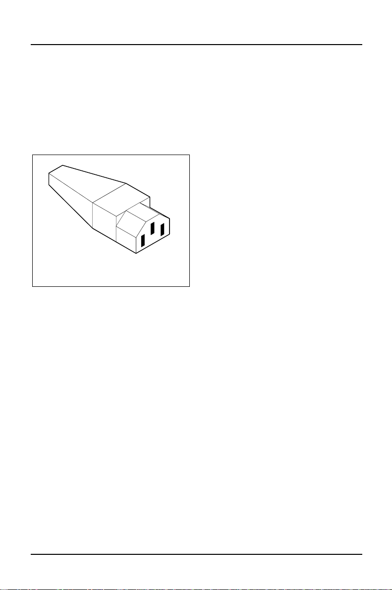
The female receptacle of the cord set
must meet CEE-22 requirements (see
Figure 1).
Figure 1
For the United States and Canada
Use a UL listed and CSA labeled cord set consisting of a three conductor cord with
a maximum length of 15 feet.
For units which stand on a desk or table, type SVT or SJT cord sets shall be used.
For units which stand on floor, only SJT type cord sets shall be used.
The cord set must be selected according to the current rating for your unit. Please
consult Table A for the selection criteria for power cords used in the United States
and Canada.
8 A26361-K423-Z202-3-7619
Page 17
Important notice concerning power cord selection Important Notes
Table A:
Cord Type Size of Conductors
in Cord
Maximum Current
Rating of Unit
SJT 18 AWG 10 Amps
16 AWG 12 Amps
14 AWG 12 Amps
SVT 18 AWG 10 Amps
17 AWG 12 Amps
For units set at 115 V:
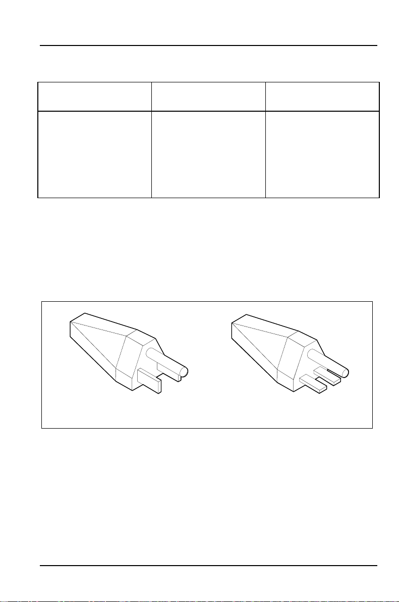
use a parallel blade, grounding type attachment plug rated 15 A, 125 V (Figure 2).
For units set at 230 V (domestic use):
use a tandem blade, grounding type attachment plug rated 15 A, 250 V
(Figure 3).
Figure 2
Figure 3
For units set at 230 V (outside of the United States and Canada):
use a cord set consisting of a minimum AWG according to Table A and a
grounding type attachment plug rated 15 A, 250 V. The cord set should have the
appropriate safety approvals for the country in which the equipment will be
installed and should be marked HAR.
A26361-K423-Z202-3-7619 9
Page 18

Important Notes Important notice concerning power cord selection
For the United Kingdom
Should the plug on the flexible cord not be of the type for your socket outlets, do
not use an adapter but remove the plug from the cord and discard. Carefully
prepare the end of the supply cord and fit a suitable plug.
WARNING
THIS APPLIANCE MUST BE EARTHED
IMPORTANT
The wires in this mains lead are coloured in accordance with the following code:
Green and Yellow: Earth
Blue: Neutral
Brown: Live
As the colours of the wires in the mains lead of this appliance may not correspond
with the coloured markings identifying the terminals in your plug, proceed as
follows:
• The wire which is coloured Green and Yellow must be connected to the
terminal in the plug which is marked with the letter E or by the earth symbol or
coloured Green or Green and Yellow.
• The wire which is coloured Blue must be connected to the terminal which is
marked with the letter N or coloured Black.
• The wire which is coloured Brown must be connected to the terminal which is
marked with the letter L or coloured Red.
10 A26361-K423-Z202-3-7619
Page 19
Preparation for use and operation
Please take note of the safety information in the chapter "Important
!
Notes".
Unpacking and checking the delivery
If you need to lift or transport the server, ask someone to help you.
!
It is recommended not to throw away the original packaging material! It may be
required for reshipment at some later date
Ê Unpack all the individual parts.
Ê Check the delivery for damage incurred during transport.
Ê Check whether the delivery agrees with the details in the delivery note.
Ê Check whether all necessary details have been entered on the first page of
the guarantee coupon booklet.
Should you discover that the delivery does not correspond to the delivery note,
notify your local sales office immediately.
If you have received drives or boards with your server, mount them before
i
installing the server. The chapter „System expansions“ will tell you how to
do this.
A26361-K423-Z202-3-7619 11
Page 20
Preparation for use and operation
Preparing the PC for use
When you set up the server for the first time, you should carry out the following
steps in the order shown. Unless otherwise specified, the steps are described in
this chapter.
1. Decide where you are going to install the server.
2. Connect the external devices to the server.
3. Check the rated voltage and connect the server to line voltage.
4. Switch the server on and follow the instructions on the screen.
Setting up the server
When installing your server, give consideration to the recommendations
!
about an ergonomic video workstation in the "Safety and ergonomics"
manual.
We recommend that you place your equipment on a surface with good
anti-slip qualities. In view of the multitude of different finishes and
varnishes used on furniture, it is possible that the rubber or aluminum feet
of the devices will mark the surface they stand on.
Do not expose the server to extreme environmental conditions (see
chapter "Technical data"). Protect it from dust, humidity and heat.
Provide at least 200 mm of clearance in front of and behind the ventilator
area of the server to ensure adequate ventilation. Do not cover the
ventilation areas of the monitor and the server.
12 A26361-K423-Z202-3-7619
Page 21

Preparation for use and operation
Connecting external devices
The power plug must be pulled out!
Read the documentation about the external device before connecting it.
!
Do not connect or disconnect cables during a thunderstorm.
Always take hold of the actual plug body. Never unplug a cable by pulling
the cable itself!
Connect and disconnect the cables in the order described below.
Connecting cables
• Turn off all power and equipment switches.
• Pull all power plugs out of the grounded-contact utility power sockets.
• Plug all cables into the server and peripherals. Please observe under all
circumstances the information provided in the chapter "Important Notes".
• Plug all data communication cables into the utility sockets.
• Position the power cable of the server in such a way that it cannot be
accidentally separated from the server.
• Plug all power cables into the grounded-contact utility power sockets.
Disconnecting cables
• Turn off all power and equipment switches.
• Pull all power plugs out of the grounded-contact utility power sockets.
• Unplug all data communication cables from the utility sockets.
• Disconnect all cables from the server and peripherals.
A26361-K423-Z202-3-7619 13
Page 22
Preparation for use and operation
Ports for external devices
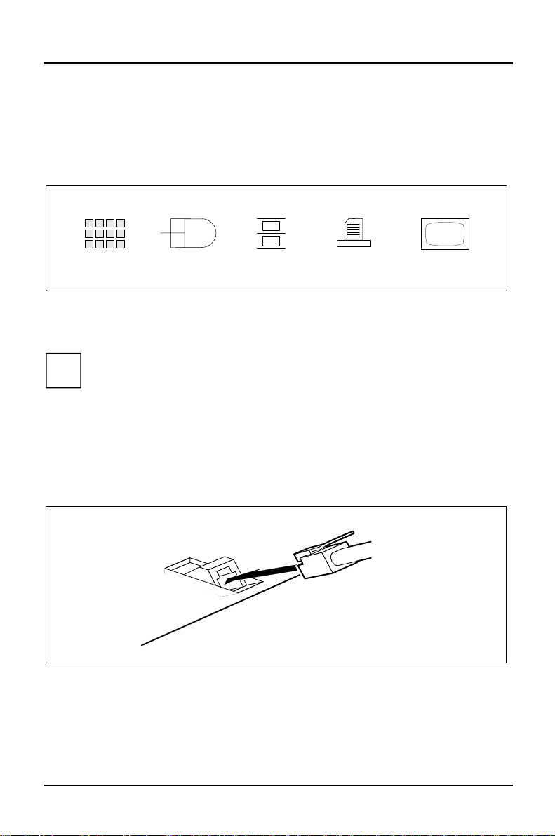
The ports for external devices are on the rear of the server. Which ports are
available on your server depend on the boards installed. The ports are indicated
by symbols. The following figure shows the symbols for the standard ports.
1
1 = Keyboard port
2 = PS/2 mouse interface
3 = Serial interface
Some of the devices that you connect require special drivers (see the
i
documentation for the connected device).
2
3 5
4 = Parallel interface
5 = Monitor interface
4
Connecting the keyboard
Ê Plug the round plug of the keyboard cable into the keyboard port on the
server.
Ê Plug the other connector of the keyboard cable into the socket on the
underside of the keyboard.
14 A26361-K423-Z202-3-7619
Page 23
Preparation for use and operation
Connecting the mouse
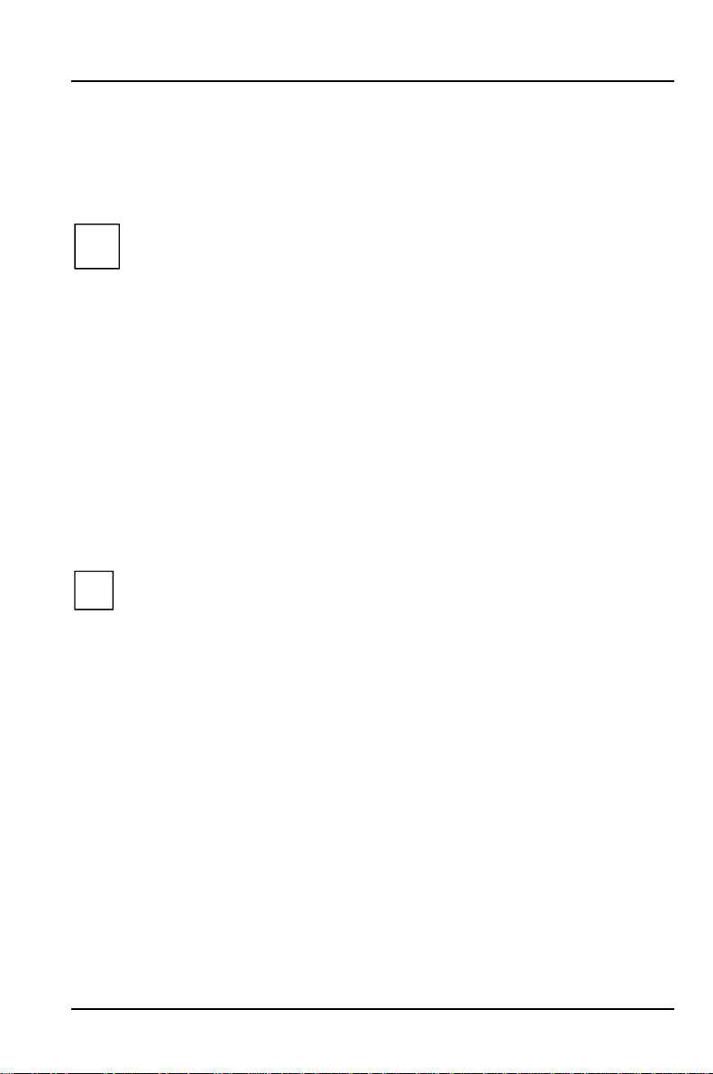
Ê Plug the connector of the mouse cable into the mouse port on the rear of the
server.
If you connect a mouse other than the one supplied, it may be necessary
i
to select a specific mouse driver in the operating system (see operating
system documentation).
If you attach a serial mouse, you can disable the mouse controller in the
BIOS Setup in order to free the IRQ12 for a different application. If the
mouse controller is disabled, you will not be able to operate a mouse
connected to the PS/2 mouse connector.
Connecting devices with serial or parallel port
Ê Connect the data cable to the external device.
Ê Connect the data cable of the external device to the appropriate port on the
server.
Most devices that you connect to the serial or parallel port require special
i
drivers. These drivers are either already integrated into the operating
system or must be installed from the floppy disk or CD supplied with the
device or application program.
If you need to change the default settings of the serial or parallel port
(e.g. address, interrupt), you can do so in the BIOS Setup. The default
settings of the ports (interfaces) are given in the Technical Manual for the
system board.
Connecting the monitor
Ê Plug the data cable of the monitor into the monitor port of the server.
A26361-K423-Z202-3-7619 15
Page 24
Preparation for use and operation
Connecting the monitor to the power voltage
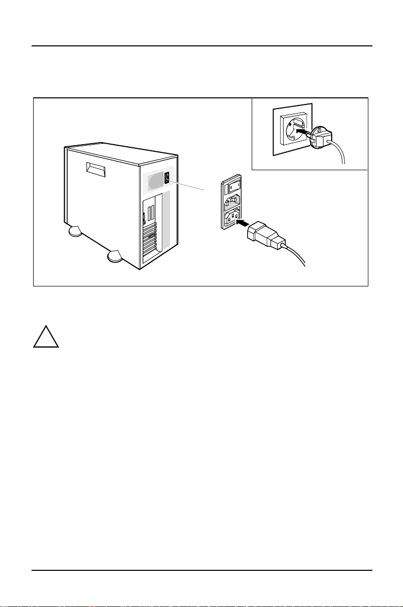
2
1
Ê Depending on the connector, plug the monitor's power cable into either the
server (1) or a power outlet (2).
If you attach a monitor other than a Siemens monitor, you must not plug
!
the monitor power cable into the monitor connector unless the rated
current of the monitor is less than 1.5 A (230 V) or 3 A (115 V). The rated
current for the monitor is also given on the monitor itself and in the
Operating Manual for the monitor.
16 A26361-K423-Z202-3-7619
Page 25
Preparation for use and operation
Connecting the server to the power voltage
230
115
1
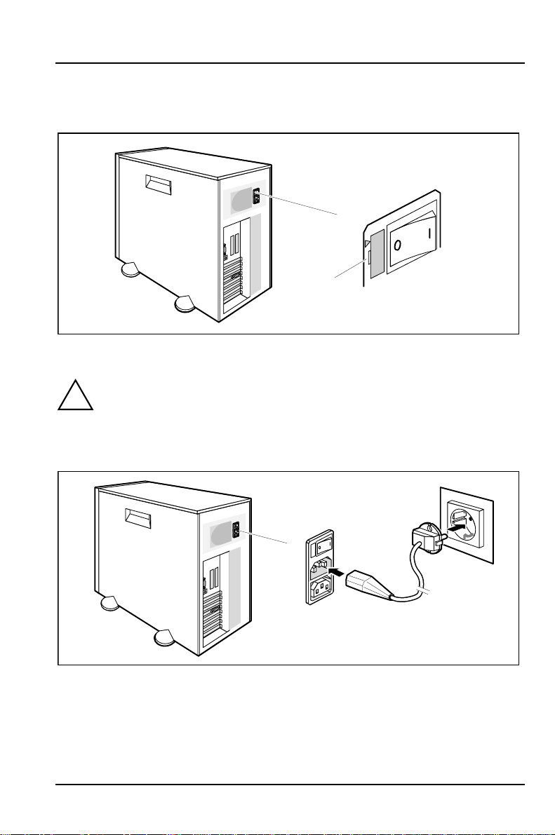
Ê Check the rated voltage.
The rated voltage must agree with the local line voltage:
!
115 = 100 V to 125 V 230 = 200V to 240V
Ê If the rated voltage does not agree with the local line voltage, lift out
the plug-in unit with a screwdriver (1), turn it and replace it.
2
1
Ê Plug the server's power cable into the server (1).
Ê Plug the server's power cable into the grounded power outlet (2).
A26361-K423-Z202-3-7619 17
Page 26
Preparation for use and operation
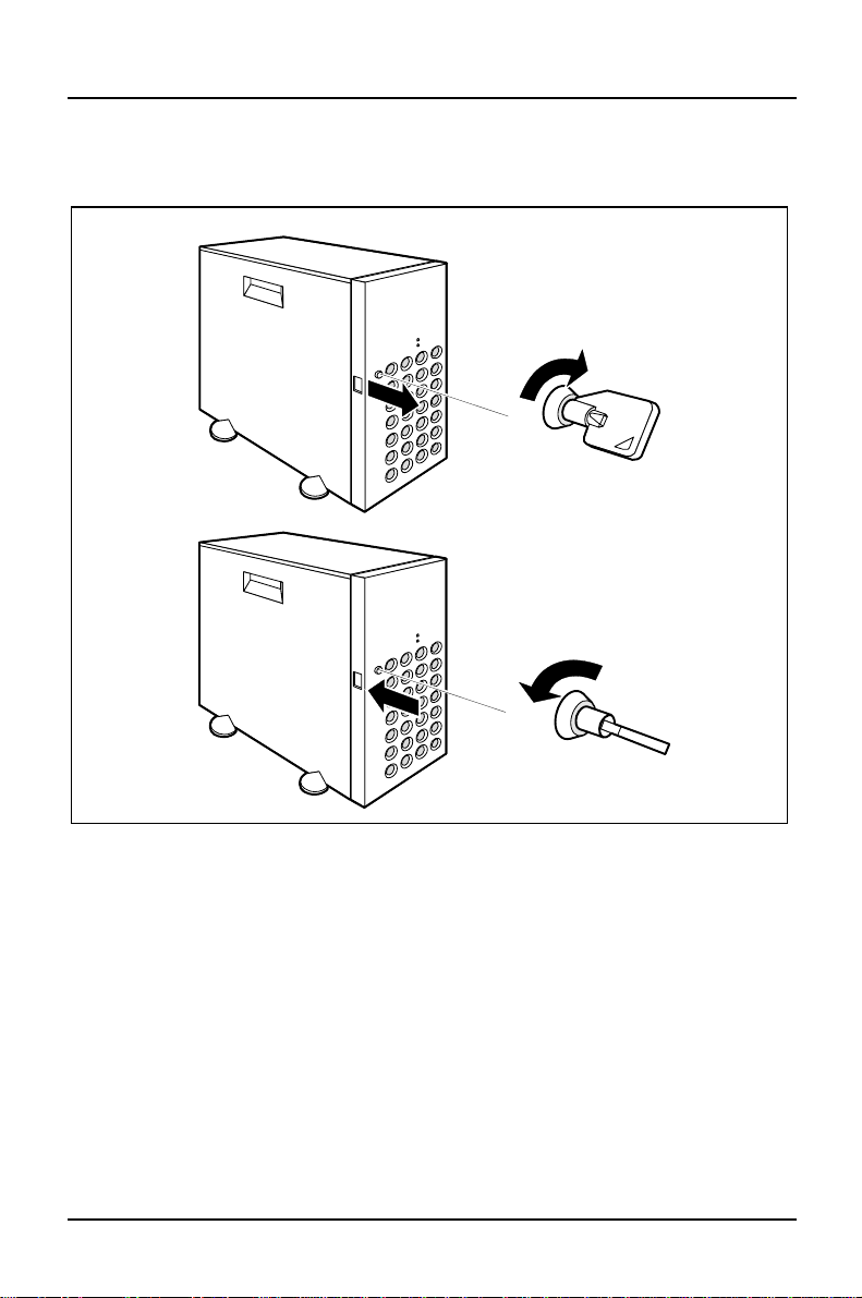
Unlocking/locking the server
2
3
1
4
Unlocking the server
Ê Turn the key clockwise (1).
Ê Open the door (2).
Locking the server
Ê Shut the door (3).
Ê Turn the key counterclockwise (4).
18 A26361-K423-Z202-3-7619
Page 27
Preparation for use and operation
Switching the server on and off
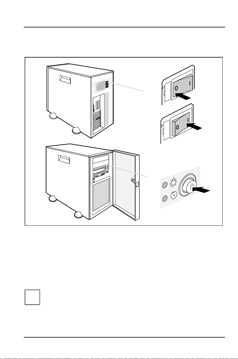
a = Main switch
b = ON/OFF switch
c = Power On display
a
0 = Server is switched off
1 = Server is ready-to-operate
115
115
230
c
230
0
1
b
With the main switch (a) you can switch the server off (position 0) or ready-tooperate (position 1). If the server is switched off, the ON/OFF switch (b) is
disabled. When the server is ready to operate, it can be switched on using the
ON/OFF switch or via a signal. If you press the ON/OFF switch again you reset the
server to ready mode.
The main switch and the ON/OFF switch do not disconnect the server
i
from the line voltage. To disconnect the line voltage completely, remove
the power plug from the grounded power outlet.
A26361-K423-Z202-3-7619 19
Page 28
Preparation for use and operation
Displays on the server
2
1
3
4
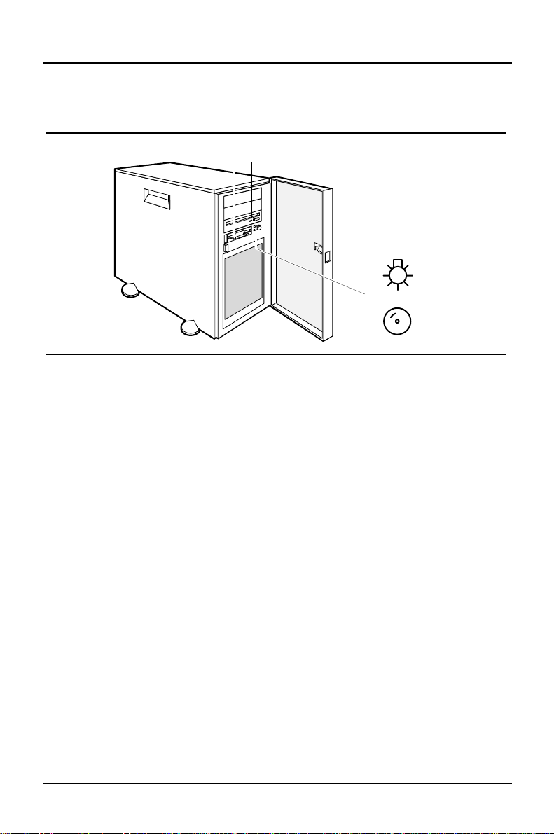
1 = Floppy disk display
2 = CD-ROM display
3 = Power On display
4 = Hard disk display
Floppy disk display
Lights up when the floppy disk drive of the server is accessed.
CD-ROM display
Lights up when the CD-ROM drive of the server is accessed.
Power On display
Lights green when the server is switched on.
Hard disk display
Lights up when the hard disk drive of the server is accessed.
20 A26361-K423-Z202-3-7619
Page 29
Preparation for use and operation
Switching on for the first time
Ê Set the monitor's brightness control to bright and switch on the monitor (see
monitor operating instructions).
Ê Open the door of the server.
Ê Switch the server on with the main switch at the rear of the server.
Ê Press the ON/OFF switch at the front of the server.
The Power ON indicator lights green.
When you switch on the server, it carries out a self-test.
If after switching on the server there is nothing but flickering stripes on the
!
screen, switch the server off immediately (see “Troubleshooting and tips -
Flickering stripes on the monitor screen“).
ServerStart
If you received the ServerStart CD for your server, you can use it to configure the
server and install the operating system. Server configuration consists of EISA
configuration using ECU, ISA configuration using ICU and disk array controller
configuration using DACCF. You will find information on operating ServerStart and
other details in the relevant description (booklet).
You can ignore the following description of server configuration and operating
system installation if you use ServerStart.
You need a CD-ROM drive for ServerStart.
A26361-K423-Z202-3-7619 21
Page 30
Preparation for use and operation
Saving the EISA configuration
If your server has a system board with EISA slots (EISA bus), you must save the
EISA configuration. You can skip this step if your server does not have a system
board with EISA slots.
The server is fully configured when it is supplied. This configuration data
!
must, however, be saved to the configuration program diskette supplied
using the EISA configuration program. Detailed information on the EISA
configuration program is provided in the associated User's Manual.
The following EISA configuration disks are supplied with your server:
• Configuration Utility Disk
• Configuration Library Disk with additional CFG files
Ê Insert the configuration utility disk in floppy disk drive. The disk must not be
write protected.
Ê Restart your server.
Having run through its self-test, the server starts the EISA configuration utility from
the floppy disk. A logo appears.
Ê Press any key to continue.
A welcome screen is displayed.
Ê Press any key to continue.
The main menu appears.
Ê Select the item Maintain system configuration diskette, and press the Enter key.
The Maintain System Configuration Diskette menu is displayed.
Press the Enter key to move forwards one menu level. Press [Esc]
i
move back one level or to Exit. Help texts are either displayed
automatically or can be called up by pressing the [F1]
22 A26361-K423-Z202-3-7619
[F1] key.
[F1][F1]
[Esc] to
[Esc][Esc]
Page 31

Preparation for use and operation
Ê Select the item Create a backup SCI file, and press the Enter key.
The Save System Configuration Information (SCI) File Descriptionwindow appears.
Ê Enter the file name and press the Enter key.
The Save System Configuration Information (SCI) File Descriptionwindow appears.
Ê Enter a description of the contents of the file, e.g., factory configuration, and
press the Enter key.
The system reports that an SCI file was created successfully.
Ê Press the Enter key to confirm the message.
The Maintain System Configuration Diskette menu is displayed.
Ê Select the item Exit and press the Enter key.
The main menu appears.
Ê Select the item Exit from this utility and press the Enter key twice.
This exits the EISA configuration program.
ICU utility
You can use the ICU utility (ISA Configuration Utility) to configure Plug&Play or
standard ISA boards. You can also use ICU to check the server system resources
(e.g. interrupts used). Using the ICU program is described in the User Guide.
Configuring the Disk Array Controller (EISA)
If your server is fitted with a Disk Array Controller (DAC) for the EISA-Bus, you
must perform the following steps:
• perform the EISA configuration for the DAC
• create a DOS system disk for the DAC configuration
• Performing DAC configuration
A26361-K423-Z202-3-7619 23
Page 32
Preparation for use and operation
Performing the EISA configuration for the DAC
Detailed information on the EISA configuration program is provided in the
i
associated User's Manual.
Ê Start the EISA configuration program.
Ê You should make the following settings:
− delayed drive switch on with six second spacing
− Fast SCSI bus
− You will find further settings in the User's Manual for the DAC.
Ê Save the new settings.
Ê Exit the EISA configuration program.
Creating a DOS system diskette for the DAC configuration
Ê Create a DOS system disk with a minimum of system files.
Ê Copy all the files from the DACCFG directory on the original disk Configuration
and Utilities onto the DOS system disk.
Ê Keep the original disk in a safe place.
Performing DAC configuration
The procedure described only roughly in places below is described in
i
detail in the User's Manual for the Disk Array Controller.
Ê Insert the newly created DOS system disk in the floppy disk drive and reboot
the server.
Ê Start the DAC configuration program DACCF from the disk.
Ê Set the Fault Management to Enabled.
(Main menu --> Advance Functions --> Hardware Parameters).
Ê Divide the hard disks into physical packs.
Ê Create one or more system drives.
Ê Initialize the system drives.
24 A26361-K423-Z202-3-7619
Page 33
Preparation for use and operation
The following steps (storing the DAC configuration on diskette) are
!
essential to enable you to restore the original configuration when a Disk
Array Controller is replaced. Data security!
Ê In the main menu select the Tools option.
Ê In the Tools menu select the Backup/Restore Config option, and then the Backup
Configuration option.
Ê Enter a file name. The file name and drive designation together may be up to
10 characters long (for example: a:\backup1).
Ê Select YES. The configuration will then be stored on the system disk.
Ê Quit the DACCF program.
Ê Restart the server.
Configuring the Disk Array Controller (PCI)
If you have a PCI bus disk array controller fitted in your server, you must configure
the disk array controller as described in this section. A DOS system disk is
supplied to the system.
Ê Start the server with the inserted DOS system disk.
Ê Remove the DOS system disk from the drive and insert the utility disk of the
DAC into the drive.
Ê In the directory DACCFG start the DAC utility DACCF and perform a DAC
configuration.
You should also make the following settings:
− delayed power-on of the drives
− Fast-SCSI bus (20 Mbyte/s)
Ê Note the information contained in the DAC manual in order to achieve optimal
system utilization and maximum performance.
Ê Be sure to save the configuration on the utility disk so that the configuration
data is available in the event of an error.
A26361-K423-Z202-3-7619 25
Page 34
Preparation for use and operation
If the current configuration data of the Disk Array Controller is lost, data
!
loss results.
Ê Quit the DACCF program.
Ê Reboot the server.
How to save the standard configuration or how to set up and then save your own
configuration is described in the Disk Array Controller manual.
Configuring the standard SCSI controller
If your server is equipped with a Fast-Wide or an Ultra-Wide SCSI-2 controller, you
must make the following settings in the configuration of the controller:
• Send start unit command = yes (delayed power-on of the drives)
• Fast-SCSI bus (20 Mbyte/s)
• Support for Ultra SCSI Speed = enabled (for Ultra-Wide-SCSI controller)
Configuring the onboard SCSI controller
If the server system board has an onboard SCSI controller, you will find a detailed
description of it in the system board Technical Manual. Further information can be
found on the supplied driver floppy disk.
Installing the operating system
Ê Insert the installation disk (boot disk) and the CD of the operating system you
want to install.
Ê Reboot the server.
Ê Follow the instructions on the screen and in the manual for the operating
system.
26 A26361-K423-Z202-3-7619
Page 35
Preparation for use and operation
Working with floppy disks and CD-ROMs
Follow the instructions supplied by the vendor of the floppy disks.
!
Never clean the server's floppy disk drives with cleaning disks. Even just
one attempt would destroy the read/write head in the disk drive within 20
seconds.
Avoid touching the surface of a CD. Handle CDs only by their edges!
!
Always store CDs in their cases. You avoid dust contamination,
scratches, bending or other damage.
Protect your CDs from dust, mechanical vibration and direct sunlight!
Avoid storing a CD in areas subject to high temperatures or humidity.
Cleaning the server
Turn off all power and equipment switches and pull the power plug out of
!
the utility power socket.
Do not clean any interior parts yourself, leave this job to a service
technician.
Do not use any cleaning agents that contain abrasives or may corrode
plastic.
Ensure that no liquid enters the system.
Ensure that the ventilation areas of the server and the monitor are free.
Wipe the server and monitor housing with a dry cloth, or if particularly dirty, use a
cloth which has been moistened in mild domestic detergent and then carefully
wrung out. If particularly dirty, use a cloth which has been moistened in mild
domestic detergent and then carefully wrung out.
Use a cloth for disinfection to clean the keyboard and the mouse.
A26361-K423-Z202-3-7619 27
Page 36

Page 37
Settings in BIOS Setup
In BIOS Setup you can set the system functions and the hardware configuration of
the server. When the server is delivered, the default entries are valid (see
Technical Manual for the system board). You can customize these settings to your
requirements in BIOS Setup.
If the Power menu is available in the BIOS setup, you must ensure that
i
the power saving functions are disabled in server operation.
If you want to change settings in BIOS Setup, you must:
• call BIOS Setup
• select the relevant menu
• select the field for the entry you want to change
• change the entry
• make other settings, if required
• save the settings and exit BIOS Setup
This chapter shows you how to call and operate BIOS Setup. The menus and
setting options provided by BIOS-Setup are described in detail in the Technical
Manual for the system board.
Calling BIOS Setup
Ê Reboot the server.
One of the following messages will be displayed at the bottom of the screen:
Press <F2> to enter Setup
Press <F1> to resume, <F2> to Setup
Ê Press the function key [F2]
If you have assigned a setup password, you must now enter this
i
password and confirm it with the Enter key.
The Main menu of BIOS Setup is displayed on the screen.
A26361-K423-Z202-3-7619 29
[F2].
[F2][F2]
Page 38
Settings in BIOS Setup Calling BIOS Setup
Phoenix BIOS Setup Copyright 1985-95 Phoenix Technologies Ltd.
Main Advanced Security Power Exit
1
System Time: [19:47:37]
System Date: [02/01/1997]
2
Diskette A: [1.4M]
Diskette B: [None]
Hard Disk 1: 850 Mbyte
Hard Disk 2: None
Hard Disk 3: None
Hard Disk 4: None
Boot Options
Video Display: [EGA/VGA]
Base Memory: 640K
Extended Memory: 15M
↑↓
4
F1 Help
ESC Exit
Select Item -/+ Change Values F9 Setup Defaults
←→
Select Menu Enter Select Sub-Menu F7 Previous Values
Item Specific Help
3
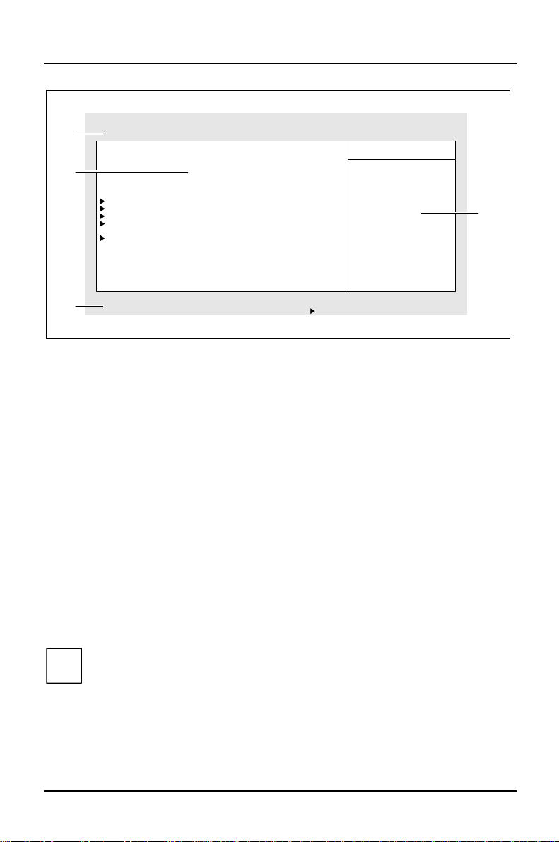
Example of the Main menu of the BIOS Setup
1 = Menu bar
2 = Working area
3 = Information area
4 = Operations bar
The BIOS Setup screen is divided into the following areas:
• Menu bar (1)
In the menu bar, you can select the different BIOS Setup menus.
• Working area (2)
The working area displays the setting options (fields) of the selected menus.
You can set the entries in the displayed fields according to your requirements.
Ê indicates fields which open further submenus. You can change entries in
these submenus.
• Information area (3)
The information area displays brief information on the selected field.
• Operations bar (4)
The operations bar indicates which keys you can use to operate BIOS Setup.
You can display more information on the functions of the keys by pressing
i
[F1]
[F1].
[F1][F1]
30 A26361-K423-Z202-3-7619
Page 39

Operating BIOS Setup Settings in BIOS Setup
Operating BIOS Setup
If you change entries in BIOS Setup, make a note of the changed entries (e g. in the
technical manual for the system board), or print out the changed screen page. To
do so, the printer must be connected to the server through the parallel interface.
Selecting menus
Use the key åååå or çççç.
Selecting fields or submenus
Use the key ÊÊÊÊ or ËËËË. The field selected is highlighted.
Selecting a submenu (marked with Ê )
Select the corresponding field, and press the Enter key. Press the [Esc]
from the submenu to its superior menu.
Changing fields
Use the key [+]
To set the default entries for the selected menu
Use the function key [F9]
Reverting the fields of the selected menu to the entries that were in effect
when BIOS Setup was called
Use the function key [F7]
Printing a screen page
Use the key combination Shift + [Print]
[+] or [-]
[-] of the numeric bloc.
[+][+]
[-][-]
[F9].
[F9][F9]
[F7].
[F7][F7]
[Print].
[Print][Print]
[Esc] to return
[Esc][Esc]
A26361-K423-Z202-3-7619 31
Page 40

Settings in BIOS Setup Exiting BIOS Setup
Exiting BIOS Setup
To exit BIOS Setup, select the Exit menu from the menu bar. You can then decide
which settings you want to save. The Exit menu offers the following options. You
must mark the required option and activate it with the Enter key.
Save Changes & Exit
Select Save Changes & Exit to save the current settings and exit the BIOS Setup. The
server is rebooted and the new settings come into effect.
Discard Changes & Exit
Select Discard Changes & Exit to discard the changes you have made. The settings
which were in force when BIOS Setup was called remain effective. BIOS Setup is
terminated and the server is rebooted.
Get Default Values
To revert all the menus of BIOS Setup to the default entries, select Get Default
Values. If you want to exit BIOS Setup with these settings, select Save Changes & Exit.
Load Previous Values
To load the values of all the menus of BIOS Setup that were in effect when BIOS
Setup was called, select Load Previous Values. If you want to exit BIOS Setup with
these settings, select Save Changes & Exit.
Save Changes
To save settings without exiting BIOS Setup, select Save Changes.
32 A26361-K423-Z202-3-7619
Page 41
Property and data protection
For protecting your system and personal data from unauthorized access, you can
use the BIOS Setup security functions.
The lockable server door also offers protection against unauthorized access and
operation of the server power switch.
The server has an anti-theft feature. At the bottom right on the rear there are two
holes through which you can feed a steel cable for securing the server to an
immovable object.
BIOS Setup security functions
The Security menu in BIOS Setup offers you various options for protecting your
system and personal data from unauthorized access. By combining these options,
you can achieve optimum protection for your system.
Detailed information of the Security menu can be found in the Technical
i
Manual for the system board. The sections "Setting the Setup password"
and "Setting the System password " describe how you set up passwords.
Preventing unauthorized BIOS Setup calls
You can activate this protection by setting a setup password in the Security menu.
In addition, you can suppress the Press F2 for Setup message in the Security
menu. This message is then no longer displayed while the server's startup routine
is in progress.
Preventing unauthorized system access
You can activate this protection by setting a system password in the Security menu.
Under System Password Mode you can also define the scope of the system
password.
Preventing unauthorized access to the settings of boards with their own
BIOS
You can activate this protection by selecting the value Extended for Setup Password
Lock field in the Security menu.
A26361-K423-Z202-3-7619 33
Page 42

Property and data protection BIOS Setup security functions
Preventing system boots from the diskette drive
You can activate this protection by selecting the value Diskette Lock for the System
Load field in the Security menu.
Activating virus warnings
You can have a warning output if the boot sector has been modified. To activate
this warning, select the value Enabled for the Virus Warning field in the Security
menu.
Preventing unauthorized writing of diskettes
To activate this protection, select the value Disabled for the Diskette Write field in
the Security menu.
Protecting BIOS from overwriting
To activate this protection, select the value Disabled for the Flash Write field in the
Security menu.
Protecting server from being switched off by a program
To activate this protection select the value Disabled for the Soft Power Off field in the
Security menu.
Protecting server from being switched on by an external device
To activate this protection select the value Disabled for the Remote Power On field in
the Security menu.
34 A26361-K423-Z202-3-7619
Page 43

BIOS Setup security functions Property and data protection
Setting the Setup password
The Setup password prevents unauthorized callup of BIOS Setup. BIOS Setup can be
called only by those who know the Setup password.
The password must be four to eight characters in length. All
i
alphanumerical characters can be used; no differentiation is made
between upper case and lower case.
Passwords are not displayed as they are entered.
If you have forgotten your passwords, please contact your technical
customer service.
To set or change the Setup password, proceed as follows:
Ê Call BIOS Setup and select the Security menu (see "Settings in BIOS Setup").
Ê Mark the Set Setup Password field and press the Enter key.
You are asked to enter a password:
Enter new Password:
Ê Enter the Setup password and press the Enter key.
You are asked to confirm the password:
Re-enter new Password:
Ê Enter the Setup password again and press the Enter key.
The new password is saved.
Changes have been saved [Continue]
You can now choose whether you want the Setup password to prevent calling of
the BIOS Setup only or in addition lock the settings of installed boards with their own
BIOS.
Ê To prevent calling of the BIOS Setup only, mark the Setup Password Lock field
and select the value Standard.
Ê To lock the settings of installed boards with their own BIOS in addition to
prevent calling of the BIOS Setup, mark the Setup Password Lock field and select
the value Extended.
If you do not want to change any other settings, you can exit BIOS Setup.
Ê Select option Save Changes & Exit in the Exit menu.
The server is rebooted and the new Setup password is effective.
A26361-K423-Z202-3-7619 35
Page 44
Property and data protection BIOS Setup security functions
Canceling Setup password
If you cancel the Setup password, you automatically deactivate the
i
system password.
To cancel the Setup password (without setting a new password):
Ê Call BIOS Setup and select the Security menu (see "Settings in BIOS Setup").
Ê Mark the Set Setup Password field and press the Enter key.
You are asked to enter a password:
Enter new Password:
Ê Press the Enter key twice.
Ê Select option Save Changes & Exit in the Exit menu.
The server is rebooted and the Setup password is canceled.
36 A26361-K423-Z202-3-7619
Page 45

BIOS Setup security functions Property and data protection
Setting the System password
The system password prevents unauthorized access to your server. With the
system password you can either prevent booting of the operating system or lock
the keyboard. The system can be accessed only by those who know the system
password.
You must also set a Setup password to make the system password effective.
The password must be four to eight characters in length. All
i
alphanumerical characters can be used; no differentiation is made
between upper case and lower case.
Passwords are not displayed as they are entered.
If you have forgotten your passwords, please contact your technical
customer service.
To set or change the system password, proceed as follows:
Ê Call BIOS Setup and select the Security menu (see "Settings in BIOS Setup").
Ê Mark the Set System Password field and press the Enter key.
You are asked to enter a password:
Enter new Password:
Ê Enter the system password and press the Enter key.
You are asked to confirm the password:
Re-enter new Password:
Ê Enter the system password again and press the Enter key.
The new password is saved.
Changes have been saved [Continue]
You can now choose whether you want the system password to prevent booting of
the operating system or lock the keyboard.
Ê To prevent booting of the operating system, mark the System Password Mode
field and select the value System.
Ê To lock the keyboard, mark the System Password Mode and select the value
Keyboard.
A26361-K423-Z202-3-7619 37
Page 46

Property and data protection BIOS Setup security functions
If you do not want to change any other settings, you can exit BIOS Setup.
Ê Select option Save Changes & Exit in the Exit menu.
The server is rebooted and the new system password is effective.
Canceling system password
To cancel the system password (without setting a new password):
Ê Call BIOS Setup and select the Security menu (see "Settings in BIOS Setup").
Ê Mark the Set System Password field and press the Enter key.
You are asked to enter a password:
Enter new Password:
Ê Press the Enter key twice.
Ê Select option Save Changes & Exit in the Exit menu.
The server is rebooted and the system password is canceled.
38 A26361-K423-Z202-3-7619
Page 47
Troubleshooting and tips
Take note of the safety hints in the manual "Safety and Ergonomics" and
!
in the chapter "Preparation for use and operation", when you connect or
disconnect cables.
If a fault occurs, try to correct it as described:
• in this chapter
• in the documentation of the connected devices
• in the help systems of the software used.
If you fail to correct the problem, proceed as follows:
Ê Switch the server off.
Ê Make a note of the steps and the circumstances that led to the fault. Also
make a note of any error messages displayed.
Ê Contact your sales office or customer service.
Power-on display remains dark after you have switched on your server
This may have the following reasons:
There is a defect in the ac power supply
Ê Check whether the power cable is plugged properly into the server and power
outlet.
Ê Switch your server on.
Internal power supply overloaded
Ê Remove the server power plug from the power outlet and wait until the power
indicator goes off.
Ê Plug the power plug into the power outlet again.
Ê Switch your server on.
A26361-K423-Z202-3-7619 39
Page 48

Troubleshooting and tips The screen stays blank
The screen stays blank
If your screen remains blank this may have the following reasons:
Monitor is switched off
Ê Switch your monitor on.
Screen has been blanked
Ê Press any key on the keyboard.
or
Ê Deactivate screen blanking (screen saver). Entering the relevant password.
Brightness control is set to dark
Ê Set the brightness control to light. For detailed information, please refer to the
Operating Manual supplied with your monitor.
Power cable or monitor cable not connected
Ê Switch off the monitor and the server.
Ê Check whether the power cable is properly connected to the monitor and
server or to the power outlet.
Ê Check whether the monitor cable is properly connected to the server and
monitor (if it is plugged in with a connector).
Ê Switch on the monitor and the server.
Wrong monitor has been set
Ê Refer to the documentation for the operating system for how to set the correct
monitor, and follow the procedure accordingly.
40 A26361-K423-Z202-3-7619
Page 49
Flickering stripes on the monitor screen Troubleshooting and tips
Flickering stripes on the monitor screen
Switch off the server immediately!
!
The flickering stripes are probably caused by an old-type screen that does not
support the horizontal frequency.
Ê Find out the horizontal frequency of your monitor screen. You will find the
horizontal frequency (also known as line frequency or horizontal deflection
frequency) in the documentation of your monitor.
Ê Refer to the documentation for your operating system for how to set the
correct horizontal frequency for your monitor, and follow the procedure
accordingly.
No screen display or display drifts
The wrong frequency and/or resolution has been selected for the screen or for the
application program.
Ê Refer to the documentation for your operating system for how to set the
correct monitor, and follow the procedure accordingly.
No mouse pointer displayed on the screen
If no mouse pointer is displayed, this may have the following causes:
Mouse driver not loaded
Ê Check whether the mouse driver is properly installed and is present when the
application program is started. Detailed information can be found in the User
Guides of the mouse, the operating system or the application program.
Mouse controller disabled
The mouse controller must be enabled, if you use the supplied mouse or a PS/2
mouse.
Ê Check in the BIOS Setup whether the mouse controller is enabled.
A26361-K423-Z202-3-7619 41
Page 50
Troubleshooting and tips The floppy disk cannot be read or written
Mouse not connected
Ê Switch the server off.
Ê Check whether the mouse cable is properly connected to the system unit.
Ê Switch your server on.
The floppy disk cannot be read or written
Ê Check whether the write protection of the floppy disk is activated.
Ê In the BIOS-Setup check the entry for the floppy disk drive.
Ê Check in the BIOS Setup whether the diskette drive controller and write
permission are enabled (see the Technical Manual for the system board).
Ê Check whether the lines of the floppy disk drive are properly connected (refer
to chapter "System expansions").
Time and/or date is not correct
Ê Set the time and/or date. You can set the time and date in the BIOS Setup.
If the time and date are repeatedly wrong when you switch on your
i
Server, the battery is flat. Change the lithium battery as described in the
Technical Manual of the system board.
42 A26361-K423-Z202-3-7619
Page 51

The system cannot be started up Troubleshooting and tips
The system cannot be started up
The system reports one of the following error messages:
Invalid configuration information
Invalid EISA configuration storage
If you receive one of these messages after system startup, the configuration
information for your EISA system has been deleted. In this case you must restore
the EISA configuration. There are two possibilities to procede: You can either
repeat the configuration procedure in its entirety (see user manual for EISA
configuration), or better still, you can reload the configuration data (SCI file) that
you saved on floppy disk back onto your system. This possibility is described
below.
EISA configuration restoring (Load SCI file)
Ê Insert the configuration utility disk in floppy disk drive. The disk must not be
write protected.
Ê Restart the server.
Having run through its power-on self-test, the system starts the EISA configuration
utility from the floppy disk.
Ê Confirm the logo screen by pressing the Enter key.
The welcome screen contains a CMOS error message. Attempt to correct the error
by running through the following two configuration procedures which are described
in detail below:
• Start by running through the EISA configuration procedure and selecting the
menu items Add or remove boards and View or edit details in order to write valid
setup information to the CMOS RAM.
• Run through the EISA configuration procedure a second time and load an SCI
file from the EISA configuration utility floppy disk.
If these measures do not help, consult your supplier or our service
i
technicians.
A26361-K423-Z202-3-7619 43
Page 52

Troubleshooting and tips The system cannot be started up
Starting at the welcome screen and the error message, proceed as follows:
Ê Press the Enter key.
The main menu appears.
Ê Select the item Configure computer and press the Enter key.
The system loads the configuration files and the Steps in configuring your computer
menu appears.
Ê Select the item Step 2: Add or remove boards and press the Enter key.
The Step 2: Add or Remove Boards screen appears.
Ê Press the function key [F10]
The Steps in configuring your computer menu appears again.
Ê Select the item Step 3: View or Edit Details and press the Enter key.
Ê Check to ensure that the following settings are correct.
− memory size
− floppy disk drives
− hard disk drives
− Video mode
Ê Press the Enter key.
The Save and exit screen appears.
Ê Select the item Save the configuration and restart the computer and press the
Enter key (if necessary, more than once) to bring up the Reboot screen.
Ê Press the Enter key to restart the system.
Having run through its self-test, the server starts the EISA configuration utility from
the floppy disk.
Ê Confirm the Logo and welcome screens by pressing the return key.
The main menu appears.
Ê Select the item Maintain system configuration diskette and press the Enter key.
The Maintain System Configuration Diskette menu is displayed.
[F10].
[F10][F10]
Ê Select the item Load SCI file and press the Enter key.
The Open System Configuration Information (SCI) filemenu appears.
44 A26361-K423-Z202-3-7619
Page 53

Error messages on the screen Troubleshooting and tips
Ê Select the factory configuration file SNICONF.SCI (or another SCI file of your
choice) and press the Enter key.
The system loads the configuration file and the Step 5: Save and exit menu appears.
Ê Select the item Save the configuration and restart the Computerand press the
Enter key.
The Reboot screen appears.
Ê Remove the floppy disk from the drive.
Ê Press the Enter key to restart the system.
Error messages on the screen
Error messages are listed in the Technical Manual of the system board and in the
documentation of the installed software.
A26361-K423-Z202-3-7619 45
Page 54

Page 55
System expansions
This chapter describes all the activities required to modify your server hardware
(e.g. installing boards or drives).
Memory and processor upgrading as well as replacement of the lithium battery are
described in the Technical Manual for the system board.
You will find a brief description of the system board on the server side
i
panel. Detailed information can be found in the system board Technical
Manual.
Opening the server
Please take note of the safety information in the chapter "Important
!
Notes".
Ê Switch the server off.
Pull the power plug out of the power outlet!
Ê If any cables attached to the server are obstructing you, pull out the
connectors on the server.
Ê Place the server in a convenient working position.
Ê Unlock the server and open the door.
Ê Read the supplied documentation before installing new drives and/or boards.
Ê Refer to the Technical Manual for the system board before making any
extensions on the system board.
A26361-K423-Z202-3-7619 47
Page 56
System expansions Opening the server
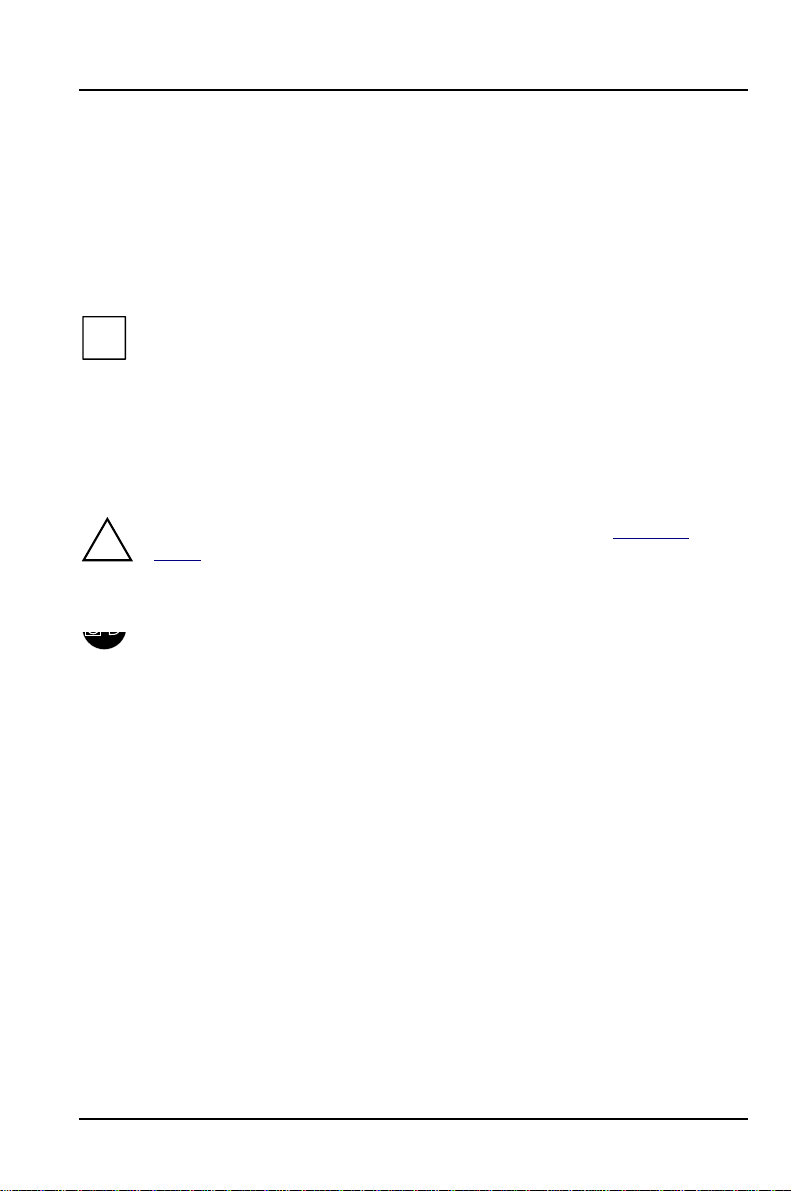
2
1
Ê Push the top panel to the right (1) as far as the stop and lift it off (2).
2
3
1
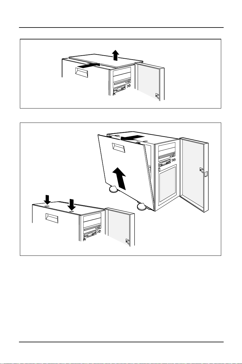
Ê Press down the two retaining clips on the left-hand side panel (1) and pull the
side panel out (2).
Ê Remove the side panel by pulling it up at an angle (3).
Ê To install or remove an accessible drive, follow the same procedure to remove
the right-hand side panel.
48 A26361-K423-Z202-3-7619
Page 57

Opening the server System expansions
To insert or remove accessible drives or to exchange the floppy disk drive, you
must also remove the front panel.
1
2
Ê Lift the door slightly (1) and remove it sideways (2).
Ê Remove the four screws.
A26361-K423-Z202-3-7619 49
Page 58
System expansions Opening the server
3
1
2
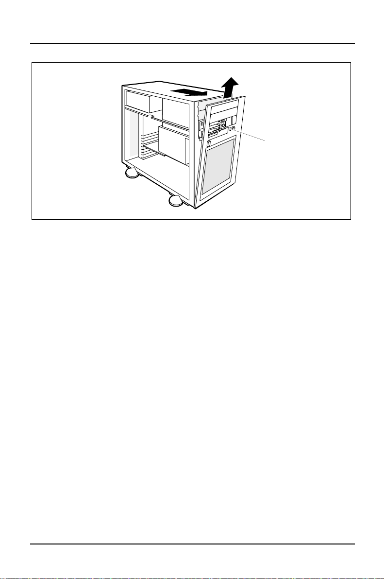
Ê Pull the front panel out at an angle (1).
Ê Carefully remove the two LEDs from the mounts on the back of the front panel
(2).
Ê Lift the front panel off at an angle (3).
50 A26361-K423-Z202-3-7619
Page 59
Assembling the server System expansions
Assembling the server
Once you have inserted or removed accessible drives or have exchanged the
floppy disk drive, first replace the front panel.
1
3
2
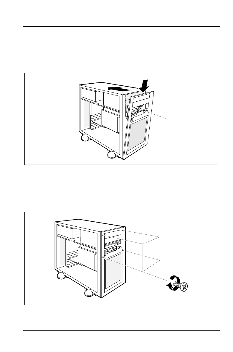
Ê Place the front panel in the depressions provided at the bottom of the server
(1).
Ê Insert the LEDs into the front panel from behind (2).
Ê Push the front panel onto the server (3). Ensure that the fan mounting is
positioned correctly in the front panel.
Ê Screw the front panel back on using the four screws.
A26361-K423-Z202-3-7619 51
Page 60
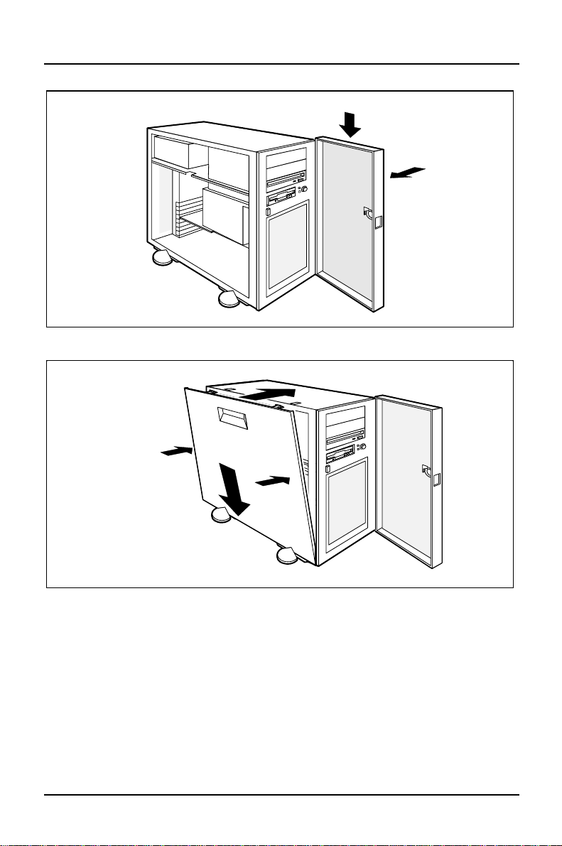
System expansions Assembling the server
2
1
Ê Replace the door (1 + 2).
2
3
1
3
Ê Place the side panel down onto the housing at an angle (1).
Ê Push the side panel onto the server (2), until the two retaining clips at the top
engage. Press the side panels firmly onto the sides (3).
Ê If you have also removed the second side panel, replace it by following the
same procedure.
52 A26361-K423-Z202-3-7619
Page 61
Assembling the server System expansions
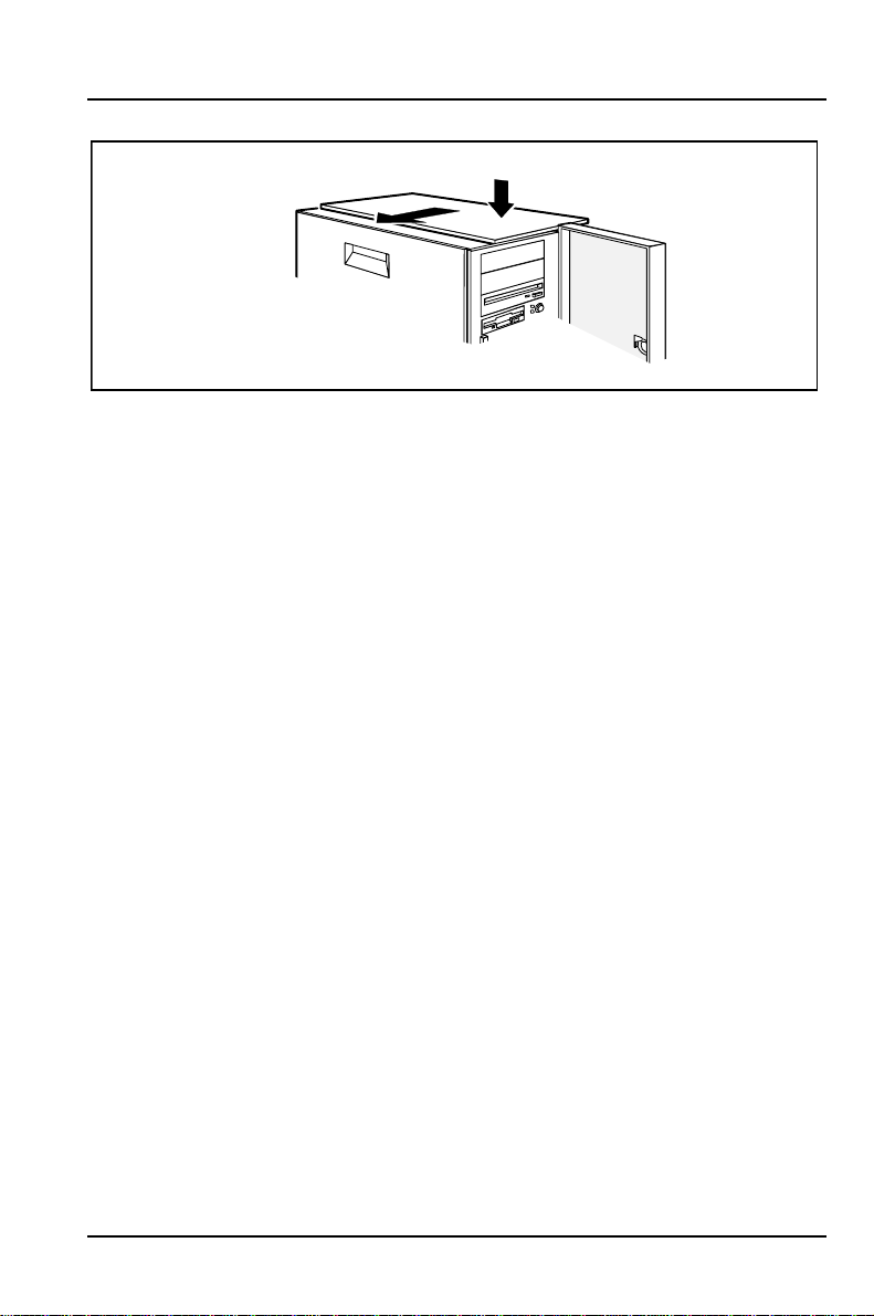
1
2
Ê Replace the top panel sideways into the guides provided on the server (1) and
push the top panel to the left as far as the stop (2).
Ê Put the server back where it is to be used and plug in the cables to the units
which were connected to the server.
Ê Plug in at the mains.
A26361-K423-Z202-3-7619 53
Page 62

System expansions Installing and removing drives
Installing and removing drives
In the server there is space for a total of four accessible drives (three 5 1/4-inch
drives and one 3 1/2-inch drive) and five non-accessible 3 1/2-inch drives with a
bay height of one inch, or three non-accessible 3 1/2-inch drives with a bay height
of 1.6 inches. A 3 1/2 inch floppy disk drive is fitted as standard.
SCSI drives
Depending on the SCSI controller used, ultra SCSI or ultra-wide SCSI hard disk
drives can be employed. However, you should always use the SCSI controller type
suitable for the particular SCSI controller.
Note that:
• Each SCSI device must be assigned its own SCSI-ID.
• A device with activated or connected terminating resistors must always be
connected at the end of an SCSI line.
• The terminating resistor may not be activated or attached on any of the
devices connected to the middle of a SCSI cable.
IDE drives
The system BIOS supports four IDE drives, regardless of whether the system
board has one or two IDE connectors.
If the system board only has one IDE connector, you can only operate the server
with two IDE drives.
If you install or remove an IDE drive, you must amend the relevant entry for the
drive in the BIOS Setup.
54 A26361-K423-Z202-3-7619
Page 63
Installing and removing drives System expansions
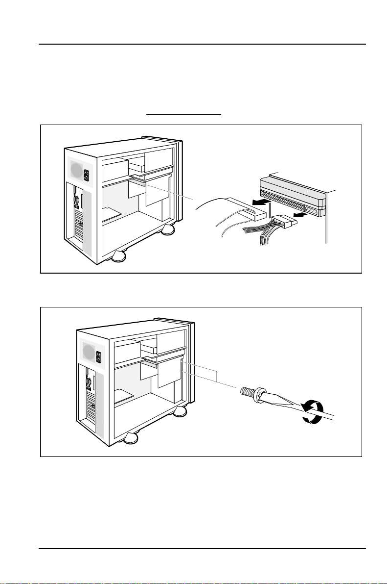
Installing or removing the hard disk drive
Ê Read the documentation supplied with the drive.
Ê Open the server (see "Opening the server").
Ê Pull the data and power connectors from the hard disk drive you want to
remove.
Ê Remove the two screws.
A26361-K423-Z202-3-7619 55
Page 64
System expansions Installing and removing drives
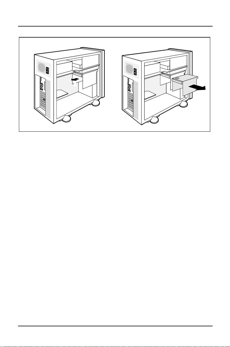
1
Ê Take the drive carrier out of the housing (1 + 2).
Ê Make the necessary settings on the hard disk drives you want to install.
2
56 A26361-K423-Z202-3-7619
Page 65
Installing and removing drives System expansions
Installing a new hard disk drive
3
1
2
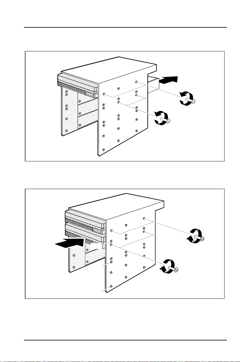
Ê Loosen the screws of installed drives (1) to prevent damage to the sealing
tape around the drives. Remove the mounting screws of the dummy drive (2)
in the required bay and remove the dummy drive (3).
1
1,6"
1,6"
2
1,6"
3
Ê Place the new drive in the drive carrier (1) and fasten it on both sides with two
screws (2). Retighten the screws of the other drives too (3).
A26361-K423-Z202-3-7619 57
Page 66
System expansions Installing and removing drives
Removing a hard disk drive
1
3
2
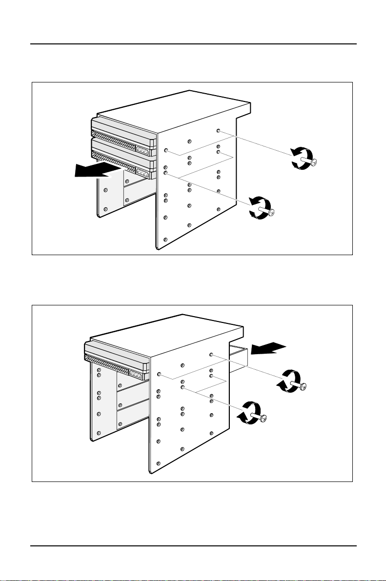
Ê Loosen the mounting screws of the drives you do not want to remove (1).
Ê Remove the screws of the drive to be removed (2) and take the drive out of
the drive carrier (3).
1
3
2
Ê Replace the drive with a dummy insert (1) and secure it with screws on both
sides (2). Retighten the mounting screws of the remaining drives (3).
58 A26361-K423-Z202-3-7619
Page 67

Installing and removing drives System expansions
1
2
Ê Put the drive carrier back in the housing (1 + 2). It is held by a retaining clip on
the drive cage.
Ê Fasten the drive carrier with the two screws removed earlier (3).
A26361-K423-Z202-3-7619 59
Page 68
System expansions Installing and removing drives
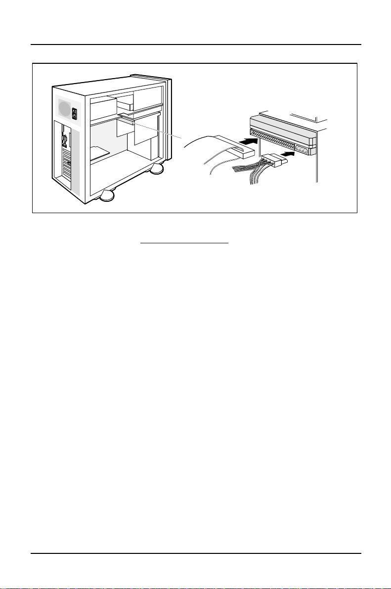
Ê Plug the data and the power supply connectors into the hard disk drives.
Ê Close the server (see "Assembling the server").
60 A26361-K423-Z202-3-7619
Page 69

Installing and removing drives System expansions
Installing an accessible drive
Ê Open the server (see "Opening the server").
2
1
Ê Remove the corresponding metal plate (1 + 2).
Ê Make the required settings on the drive.
2
1
2
1
Ê Slide the drive into its bay (1).
Ê Fasten the drive with the four screws (2).
A26361-K423-Z202-3-7619 61
Page 70
System expansions Installing and removing drives
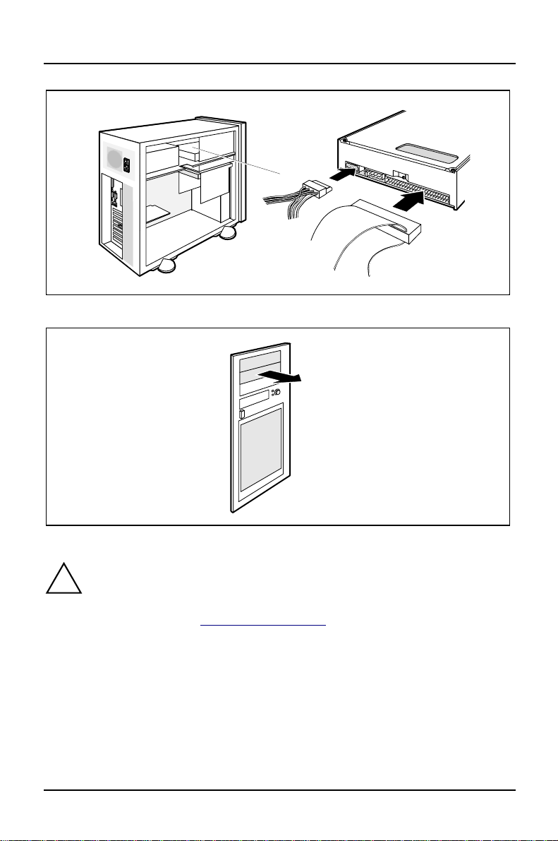
Ê Plug the connectors of the data and the power line into the drive.
Ê Remove the plastic drive cover from the front cover.
Do not throw away the two covers (plastic cover and metal plate). If you
!
remove the drive again later, you will have to reinstall the covers.
Ê Close the server (see "Assembling the server").
62 A26361-K423-Z202-3-7619
Page 71
Installing and removing drives System expansions
Removing an accessible drive
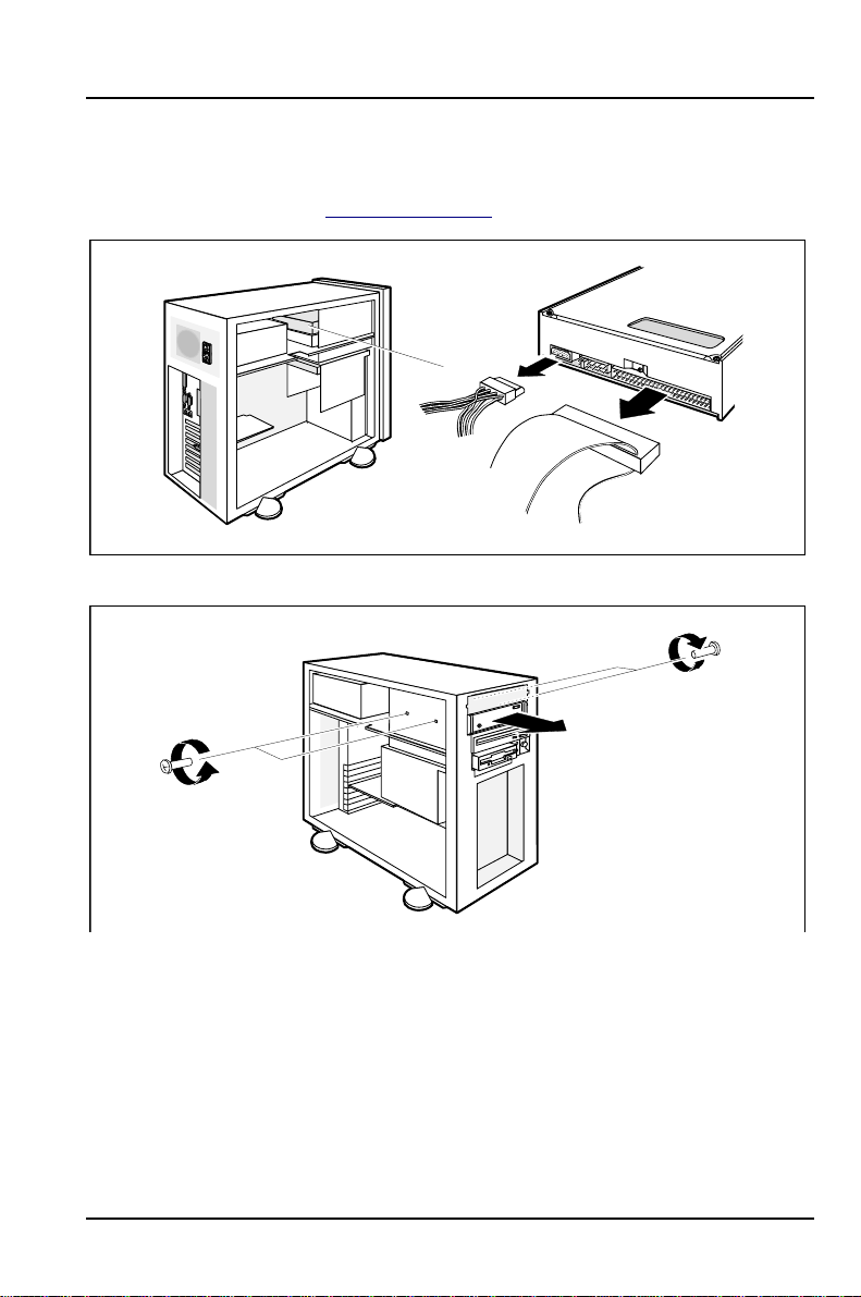
Ê Open the server (see "Opening the server").
Ê Pull the lines from the drive.
1
1
Ê Remove the four screws (1).
Ê Slide the drive out of its bay (2).
A26361-K423-Z202-3-7619 63
2
Page 72
System expansions Installing and removing drives
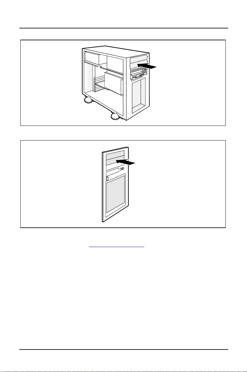
Ê Press the metal plate into place.
Ê Press the plastic drive cover into place. You must feel it engage.
Ê Close the server (see "Assembling the server").
64 A26361-K423-Z202-3-7619
Page 73
Installing and removing drives System expansions
Changing the floppy disk drive
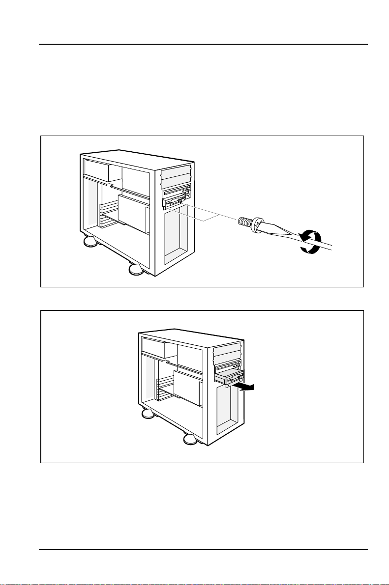
Ê Open the server (see "Opening the server").
Ê Pull the data line of the floppy disk drive from the system board (see Technical
Manual of the system board).
Ê Remove the two screws.
Ê Pull the floppy disk drive and the carrier a little way out of the housing.
A26361-K423-Z202-3-7619 65
Page 74

System expansions Installing and removing drives
Ê Pull all line connectors from the floppy disk drive.
Ê Remove the four screws that fix the floppy disk drive to the carrier.
66 A26361-K423-Z202-3-7619
Page 75

Installing and removing drives System expansions
Ê Fasten the new floppy disk drive to the carrier using the screws you removed
earlier.
Ê Plug the connectors of the data and power line into the floppy disk drive.
A26361-K423-Z202-3-7619 67
Page 76
System expansions Installing and removing drives
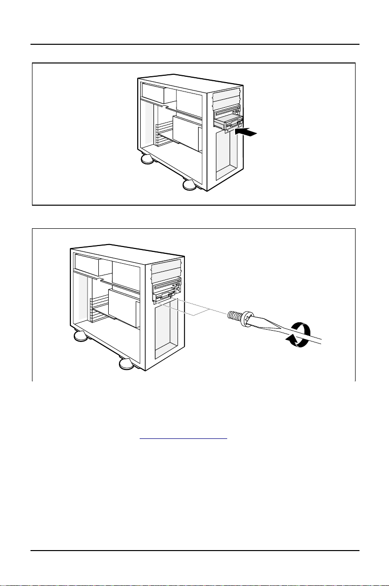
Ê Put the floppy disk drive and the carrier back into the housing.
Ê Fasten the carrier with the screws removed earlier.
Ê Plug the data line to the corresponding connector on the system board (see
Technical Manual of the system board).
Ê Close the server (see "Assembling the server").
Ê If the new floppy disk drive has different parameters from the old one, amend
the corresponding entry in the BIOS Setup.
68 A26361-K423-Z202-3-7619
Page 77
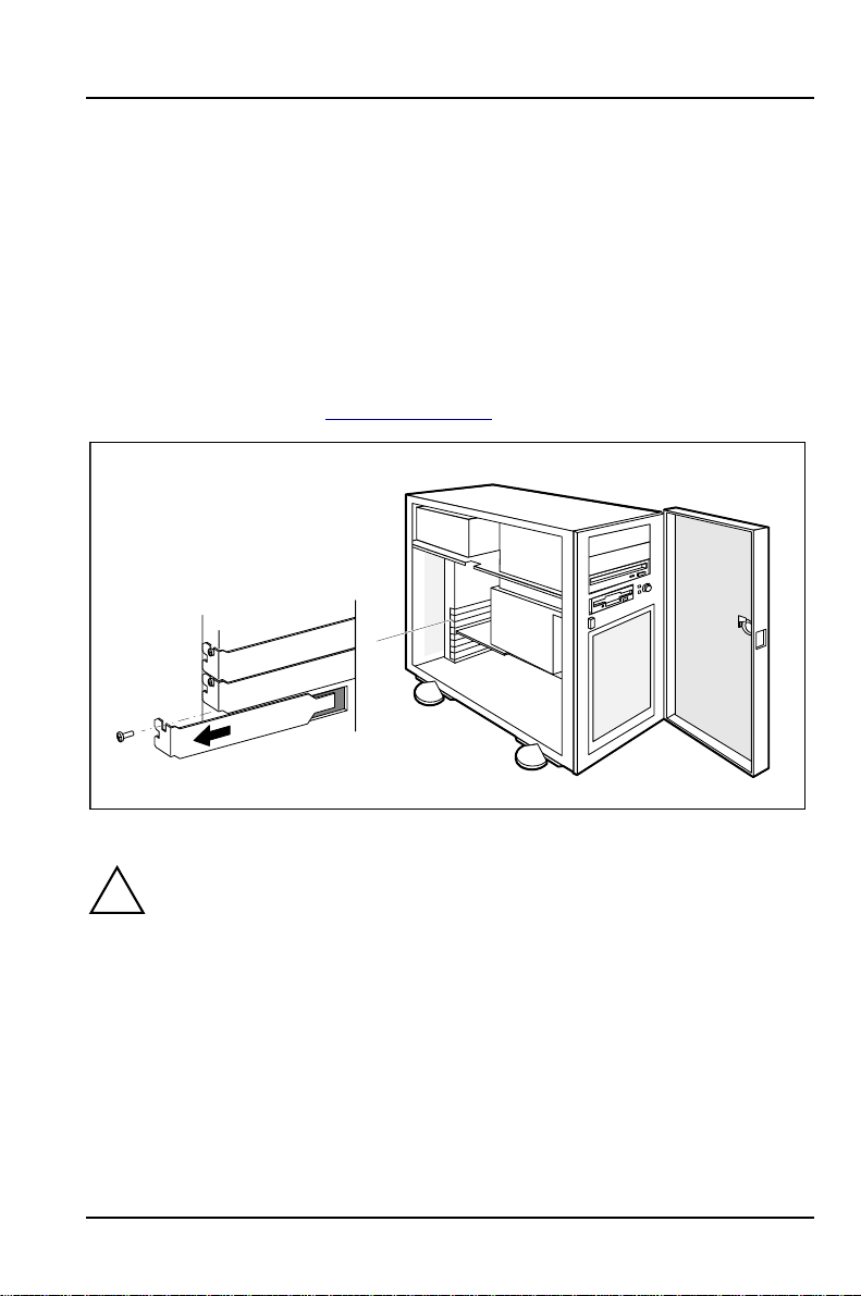
Installing and removing boards System expansions
Installing and removing boards
The server can be extended with ISA, EISA and PCI boards, depending on the
slots available on the system board.
Installing a board
Ê Read carefully the documentation supplied with the board.
Ê Open the server (see "Opening the server").
1
2
Ê Remove the screw (1) and take out the rear slot cover plate (2).
Do not dispose of the rear slot cover plate. For cooling, protection against
!
fire and in order to comply with EMC regulations, you must refit the rear
slot cover plate if you remove the board.
A26361-K423-Z202-3-7619 69
Page 78
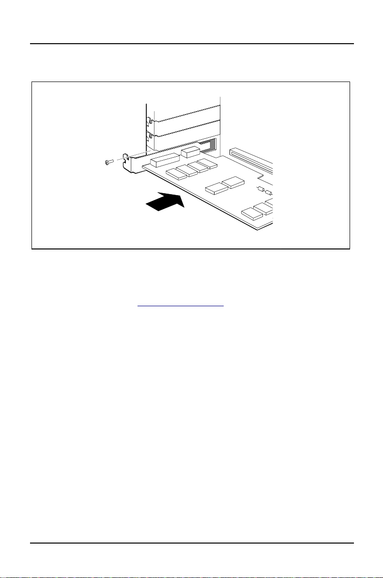
System expansions Installing and removing boards
Ê Take your board out of its packaging.
2
1
Ê Put the board in the required slot and push it carefully in place (1). Ensure that
the board is then fully in place.
Ê Fix the board using the screw removed previously (2).
Ê Close the server (see "Assembling the server").
Ê If the system board has EISA slots, reconfigure the server with the EISA
configuration program.
70 A26361-K423-Z202-3-7619
Page 79
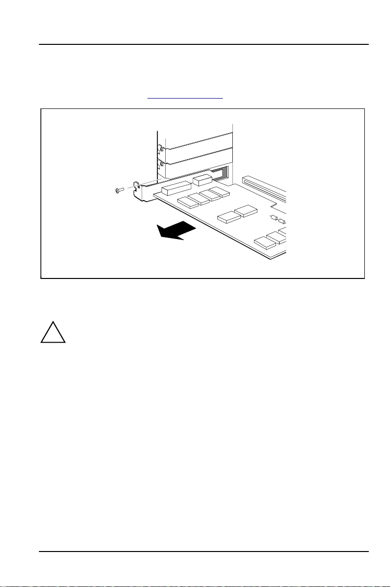
Installing and removing boards System expansions
Removing a board
Ê Open the server (see "Opening the server").
1
2
Ê Remove the screw (1) and pull the board out of the slot (2).
Ê Place the board into an appropriate packaging.
For cooling, protection against fire and in order to comply with EMC
!
regulations, you must refit the rear slot cover plate.
A26361-K423-Z202-3-7619 71
Page 80
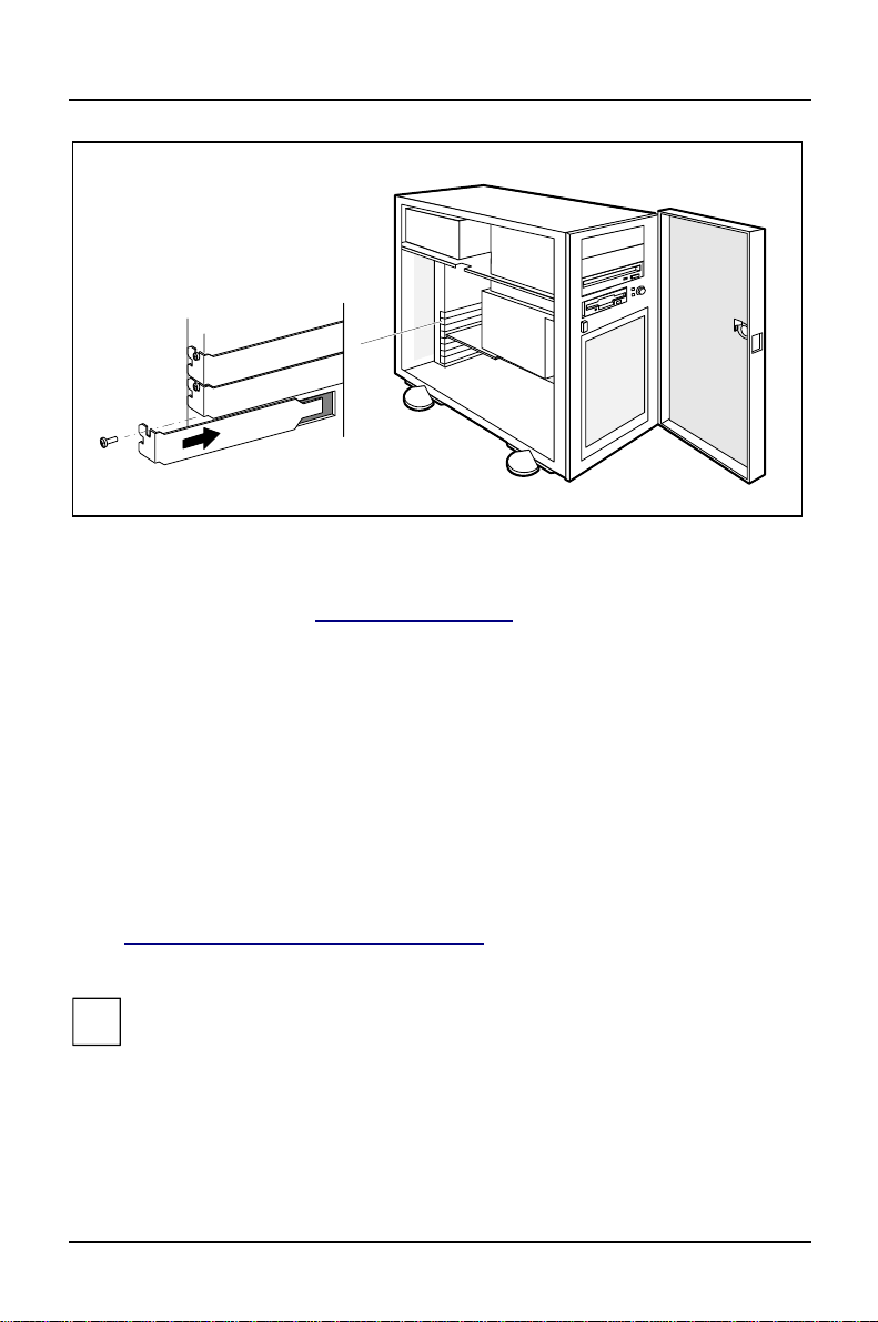
System expansions Installing the RTDS hard disk drive
2
1
Ê Put the rear slot cover plate carefully into place (1).
Ê Fasten the rear slot cover plate with the screw you removed earlier (2).
Ê Close the server (see "Assembling the server").
Ê If the system board has EISA slots, reconfigure the server with the EISA
configuration program.
Installing the RTDS hard disk drive
In order to use the Remote Test and Diagnosis System (RTDS) on the server, you
must install the optional RTDS hard disk drive which contains the RTDS. The
RTDS hard disk has an IDE interface.
The RTDS hard disk drive can be mounted in the server in a hard disk drive carrier
(see "Installing or removing the hard disk drive") or installed in a mounting frame
and mounted in a bay for accessible drives by a service technician.
You may also retro-install the RTDS software on an IDE hard disk. Refer
i
to the documentation of Server Management and Remote TDS for further
information.
72 A26361-K423-Z202-3-7619
Page 81

Extensions on the system board System expansions
Extensions on the system board
Ê Open the server (see "Opening the server").
Ê If you want to upgrade the main memory and the main memory slots are
obstructed by the hard disk drive carrier, remove the hard disk drive carrier
(see "Installing or removing the hard disk drive").
Ê If you want to upgrade (exchange) the processor and the processor socket is
obstructed by the cage for accessible drives, please contact our service
department.
Ê Make the desired expansions or settings.
Details of how you upgrade the main memory or video memory of your server,
replace the lithium battery or processor or make certain settings are provided in
the Technical Manual for the system board.
Ê If you have removed the slot board, insert it again (see "Installing or removing
the hard disk drive").
Ê Close the server (see "Assembling the server").
A26361-K423-Z202-3-7619 73
Page 82

Page 83

Technical data
Electrical data (server)
Rated voltage range: (selectable) 100V-125V/200V-240V
Frequency: 50 Hz - 60 Hz
Rated current in basic configuration:
• Server without monitor socket
Max. rated current:
• Server without monitor socket
• Server with monitor socket
• Monitor socket
Protection class: I
Regulations complied with: EN 60950 / VDE 0805
Dimensions
Width:
Depth:
Height:
Weight:
Environmental conditions
PRIMERGY 351 360
100 V - 125 V / 0.7 A 1.8 A
200 V - 240 V / 0.4 A 1.0 A
PRIMERGY 351 360
100 V - 125 V / 3.5 A 6.0 A
200 V - 240 V / 2.0 A 3.5 A
100 V - 125 V / 6.5 A 9.0 A
200 V - 240 V / 3.5 A 5.0 A
100 V - 125 V / 3.0 A 3.0 A
200 V - 240 V / 1.5 A 1.5 A
220 mm / 302 mm including feet
472 mm
484 mm including feet
appr. 14 kg (137 N) in basic
configuration
Environment class 3K2
Environment class 2K2
Temperature:
• Operating (3K2)
• Transport (2K2)
Condensation in operating must be avoided.
A26361-K423-Z202-3-7619 75
DIN IEC 721 part 3-3
DIN IEC 721 part 3-2
15 °C .... 32 °C
-25 °C .... 60 °C
Page 84

Technical data
Clearance required to ensure adequate ventilation:
• front
• rear
Noise level
min. 200 mm
min. 200 mm
Sound power level L
(ISO 9296): ≤ 5.6 B
WAd
Sound pressure level
at bystander position LpAm (ISO 9296): ≤ 40 dB
76 A26361-K423-Z202-3-7619
Page 85

Index
19
3
3 1/2 inch floppy drive
replacing 65
A
Accessible drive
installing 61
removing 63
B
Batteri 3
Battery 3, 42, 47
BIOS 54
protecting boards with own BIOS 33
BIOS Setup 29
activating write-protection 34
calling 29
exiting 32
Main menu 30
operating 31
preventing calling 33
saving 32
security functions 33
write protection 33
Board
installing 69
removing 69, 71
safety 5
Boot disk 26
C
Cable
connecting 13
disconnecting 13
CD-ROM
working with 27
A26361-K423-Z202-3-7619 77
Page 86

Index
CD-ROM display 20
CE certificate 6
CFG Library Disk 22
CMOS error message 43
CMOS-RAM 43
Configuration Utility Disk 22
Configuration, BIOS Setup 29
Contents of delivery 11
Cover 62, 64
Current draw, monitor 15
D
DAC configuration 23, 25
DACCF 21, 25
Dark screen 40
Data protection 33
Date, not correct 42
Device
connecting 13
interface 14
Dimensions 75
Disk Array Controller
configuring 23, 25
Disk Array Controller Configuration 21
Display
on server 20
power-on display fails to light 39
Disposal 6
DOS
creating system disk 23
Drifting screen display 41
Drive 54
changing a 3 ½ inch floppy disk drive 65
installing 54
installing an accessible drive 61
removing 54
removing an accessible 63
Drive carrier
installing 59
removing 55
E
ECU 21, 22
78 A26361-K423-Z202-3-7619
Page 87

EISA configuration 21, 22, 23, 43, 70, 72
restoring 43
saving 22
EISA configuration program 22
EISA Configuration Utility 22
EISA Disk Array Controller
configuring 23
Electrical data 75
Electromagnetic compatibility 6
EMC 6
regulations 69
EMC regulations 71
Ergonomic
video workstation 12
Error
date not correct 42
drifting screen display 41
flickering stripes on the monitor screen 41
floppy disk cannot be read or written 42
message on the screen 45
no mouse pointer 41
power-on display fails to light 39
screen stays blank 40
system cannot be started up 43
time not correct 42
ESD 5
Extensions, on the system board 73
External devices, ports 14
Index
F
Fast SCSI 54
Fast-Wide SCSI 54
Fast-Wide SCSI 2 Controller
configuring 26
Flickering stripes on the monitor screen 41
Floppy disk
cannot be read or written 42
working with 27
Floppy disk controller 42
Floppy disk display 20
Floppy disk drive
activating write-protection 34
changing 65
A26361-K423-Z202-3-7619 79
Page 88

Index
G
Guarantee coupon booklet 11
H
Hard disk display 20
Hard disk drive
installing 55, 57
removing 55, 58
I
ICU 21, 23
ICU utility 23
IDE
drive 54
hard disk drive 72
interface 72
port 54
Important notes 3
Information
further 1
general 1
Installation disk 26
Installing, TDS hard disk drive 72
Interfaces 14
Interrupt 12 15
Introduction 1
IRQ12 15
ISA
configuration 21, 23
Configuration Utility 23
K
Keyboard
cleaning 27
connecting 14
locking 37
symbol 14
L
Laser 4
Laserhänvisning 4
Laserinformation 4, 5
Laser-ohje 5
80 A26361-K423-Z202-3-7619
Page 89

Lithium battery 3, 42, 47, 73
M
Main memory 73
Main menu
BIOS Setup 30
Main switch 19
Message
error 45
Metal cover
inserting 64
removing 62
Monitor
cleaning 27
connecting 15
flickering stripes on the screen 41
symbol 14
Monitor screen
error message 45
Mouse
cleaning 27
connecting 15
controller 15
no mouse pointer 41
symbol 14
Mouse pointer, not displayed 41
Index
N
No mouse pointer 41
No screen display 40, 41
Noise level 76
Notational conventions 2
Notes
CD-ROM 27
CE certificate 6
disposal and recycling 6
floppy disk 27
important 3
laser 4
safety 3
O
ON/OFF switch 19
A26361-K423-Z202-3-7619 81
Page 90

Index
Operating system
installing 26
preventing startup 33
Overview 1
preparing for use 12
P
Packing material 11
Parallel port
connecting devices 15
symbol 14
Password
canceling Setup password 36
canceling system password 38
changing Setup password 35
setting system password 37
setting the Setup password 35
Plastic cover
inserting 64
removing 62
Plug&Play 23
Ports, external devices 14
Power-on display 19, 20
fails to light 39
Preparing for use, overview 12
Processor 73
Property protection 33
Protection
against remote power off 34
against remote power on 34
PS/2 mouse
symbol 14
R
Rated voltage
checking 17
setting 17
Recycling 6
Remote power off
activating protection against 34
Remote power on
activating protection against 34
Remote Test and Diagnosis System 72
82 A26361-K423-Z202-3-7619
Page 91

RTDS 72
S
Safety 3
board 5
SCI file 43
loading 43
Screen
stays blank 40
SCSI
controller 54
drives 54
ID 54
Security function 33
BIOS Setup 33
Serial port
connecting devices 15
symbol 14
Server
assembling 51
cleaning 27
connecting 13
connecting to power voltage 17
display 20
locking 18
opening 47
ports 14
setting up 12
switching off 19
switching on 19, 21
transporting 6
unlocking 18
ServerStart, CD 21
Settings
BIOS Setup 29
protecting boards with own BIOS 33
Setup 29 see BIOS Setup
Setup Password
canceling 36
changing 35
setting 35
Sound pressure level 76
Standard SCSI Controller
Index
A26361-K423-Z202-3-7619 83
Page 92

Index
configuring 26
Summer time 42
Surface 75
Switching on for the first time 21
Symbols 14
Symbols, explanation of 2
System BIOS 54
System board
extensions 73
System boot
from diskette drive preventing 34
locking 37
System disk
creating 23
System expansions 47
System Password
canceling 38
setting 37
System settings
BIOS Setup 29
System startup
preventing 33
T
Technical data 75
Terminating resistor 54
Time, not correct 42
Tips 39
Trouble
date not correct 42
drifting screen display 41
flickering stripes on the monitor screen 41
floppy disk cannot be read or written 42
message on the screen 45
no mouse pointer 41
power On display fails to light 39
screen stays blank 40
system cannot be started up 43
time not correct 42
Troubleshooting 39
U
Utility ICU 23
84 A26361-K423-Z202-3-7619
Page 93

V
Video memory 73
Video workstation
setting up 12
Virus warning
activating 34
W
Wide-SCSI 54
Winter time 42
Write protection
BIOS Setup 33, 34
floppy disk drive 34
Wrong date 42
Wrong time 42
Index
A26361-K423-Z202-3-7619 85
Page 94

Information on this document
On April 1, 2009, Fujitsu became the sole owner of Fujitsu Siemens Computers. This new subsidiary of Fujitsu has been renamed Fujitsu Technology Solutions.
This document from the document archive refers to a product version which
was released a considerable time ago or which is no longer marketed.
Please note that all company references and copyrights in this document have
been legally transferred to Fujitsu Technology Solutions.
Contact and support addresses will now be offered by Fujitsu Technology Solutions and have the format …@ts.fujitsu.com.
The Internet pages of Fujitsu Technology Solutions are available at
http://ts.fujitsu.com/...
and the user documentation at http://manuals.ts.fujitsu.com.
Copyright Fujitsu Technology Solutions, 2009
Hinweise zum vorliegenden Dokument
Zum 1. April 2009 ist Fujitsu Siemens Computers in den alleinigen Besitz von
Fujitsu übergegangen. Diese neue Tochtergesellschaft von Fujitsu trägt seitdem den Namen Fujitsu Technology Solutions.
Das vorliegende Dokument aus dem Dokumentenarchiv bezieht sich auf eine
bereits vor längerer Zeit freigegebene oder nicht mehr im Vertrieb befindliche
Produktversion.
Bitte beachten Sie, dass alle Firmenbezüge und Copyrights im vorliegenden
Dokument rechtlich auf Fujitsu Technology Solutions übergegangen sind.
Kontakt- und Supportadressen werden nun von Fujitsu Technology Solutions
angeboten und haben die Form …@ts.fujitsu.com.
Die Internetseiten von Fujitsu Technology Solutions finden Sie unter
http://de.ts.fujitsu.com/..., und unter http://manuals.ts.fujitsu.com finden Sie die
Benutzerdokumentation.
Copyright Fujitsu Technology Solutions, 2009
 Loading...