

Page 1
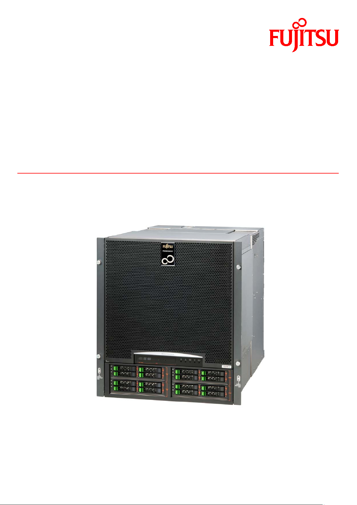
FUJITSU Server
PRIMEQUEST 1000
Tool Reference
Series
C122-E110-10EN
Page 2

Page 3

PRIMEQUEST 1000 Series Tool Reference
Preface
Preface
This manual provides information on operation methods and settings, including details on the MMB, PSA, and EFI
functions. The manual is intended for system administrators.
For details on the regulatory compliance statements and safety precautions, see the PRIMEQUEST 1000 Series
Safety and Regulatory Information (C122-E115XA).
Errata and addenda for the manual
The PRIMEQUEST 1000 Series Errata and Addenda (C122-E119EN) provides errata and addenda for the manual.
Read the PRIMEQUEST 1000 Series Errata and Addenda (C122-E119EN) thoroughly in reference to the manual.
For Safe Operation
How to use this manual
This manual contains important information about the safe use of this product. Read the manual thoroughly to
understand the information in it before using this product. Be sure to keep this manual in a safe and convenient
location for quick reference.
Fujitsu makes every effort to prevent users and bystanders from being injured and to prevent property damage. Be
sure to use the product according to the instructions in the manual.
About this product
This product is designed and manufactured for standard applications. Such applications include, but are not limited
to, general office work, personal and home use, and general industrial use. The product is not intended for
applications that require extremely high levels of safety to be guaranteed (referred to below as "safety-critical"
applications). Use of the product for a safety-critical application may present a significant risk of personal injury
and/or death. Such applications include, but are not limited to, nuclear reactor control, aircraft flight control, air
traffic control, mass transit control, medical life support, and missile launch control. Customers shall not use the
product for a safety-critical application without guaranteeing the required level of safety. Customers who plan to
use the product in a safety-critical system are requested to consult the Fujitsu sales representatives in charge.
Storage of accessories
Keep the accessories in a safe place because they are required for server operations.
Organization and Notation of This Manual
This section describes the following topics:
- Organization of this manual
- Manuals for the PRIMEQUEST 1000 series
- Related manuals
- Abbreviations
- Notation
- Notation for the CLI (command line interface)
- Notes on notations
- Alert messages
- Product operating environment
- Trademarks
i C122-E110-10EN
Page 4

PRIMEQUEST 1000 Series Tool Reference
Preface
Organization of this manual
This manual is organized as follows.
CHAPTER 1 MMB Web-UI (Web User Interface) Operations
Chapter 1 describes the menus used to manage and operate the PRIMEQUEST 1000 series server with the
MMB Web-UI. It also describes how to use the MMB Web-UI.
CHAPTER 2 MMB CLI (Command Line Interface) Operations
Chapter 2 describes the CLI (command line interface) provided by the MMB.
CHAPTER 3 PSA Web-UI (Web User Interface) Operations
Chapter 3 lists the menus used to operate PSA with the MMB Web-UI. It also describes the window and
menu operations for PSA operations.
CHAPTER 4 PSA CLI (Command Line Interface) Operations
Chapter 4 describes the commands for operating PSA from the CLI.
CHAPTER 5 UEFI Menu Operations
Chapter 5 describes the menu operations of the UEFI.
CHAPTER 6 UEFI Command Operations
Chapter 6 describes the command operations of the UEFI.
APPENDIX A Lists of Settings
Appendix A lists the setting items for each window.
Index
The index lists keywords and the pages that they refer to, helping readers quickly find the necessary
information in the manual.
Manuals for the PRIMEQUEST 1000 series
The following manuals have been prepared to provide you with the information necessary to use the PRIMEQUEST
1000 series.
You can access HTML versions of these manuals at the following sites:
Japanese-language site: http://jp.fujitsu.com/platform/server/primequest/manual/
Global site: http://jp.fujitsu.com/platform/server/primequest/manual-e/
Title Description Manual code
PRIMEQUEST 1000 Series
Getting Started Guide
PRIMEQUEST 1000 Series
Safety and Regulatory
Information
PRIMEQUEST 1000 Series
Errata and Addenda
Describes what manuals you should read and how to
access important information after unpacking the
PRIMEQUEST 1000 series server. (This manual comes
with the product.)
Contains important information required for using the
PRIMEQUEST 1000 series safely.
Provides errata and addenda for the PRIMEQUEST
1000 series manuals. This manual will be updated as
needed.
ii C122-E110-10EN
C122-E114XA
C122-E115XA
C122-E119EN
Page 5

PRIMEQUEST 1000 Series Tool Reference
Preface
Title Description Manual code
PRIMEQUEST 1000 Series
General Description
Fujitsu M10/SPARC M10
Systems/SPARC Enterprise/
PRIMEQUEST Common
Installation Planning
Manual
PRIMEQUEST 1000 Series
Hardware Installation
Manual
PRIMEQUEST 1000 Series
Installation Manual
PRIMEQUEST 1000 Series
User Interface Operating
Instructions
PRIMEQUEST 1000 Series
Administration Manual
Describes the functions and features of the
PRIMEQUEST 1000 series.
Provides the necessary information and concepts you
should understand for installation and facility planning
for SPARC M10 Systems, SPARC Enterprise, and
PRIMEQUEST installations.
Includes the specifications of and the installation
location requirements for the PRIMEQUEST 1000
series.
Describes how to set up the PRIMEQUEST 1000 series
server, including the steps for installation preparation,
initialization, and software installation.
Describes how to use the Web-UI and UEFI to assure
proper operation of the PRIMEQUEST 1000 series
server.
Describes how to use tools and software for system
administration and how to maintain the system
(component replacement and error notification).
C122-B022EN
C120-H007EN
C122-H004EN
C122-E107EN
C122-E109EN
C122-E108EN
PRIMEQUEST 1000 Series
Tool Reference
PRIMEQUEST 1000 Series
Message Reference
PRIMEQUEST 1000 Series
REMCS Installation Manual
PRIMEQUEST 1000 Series
Glossary
PRIMEQUEST 1000 Series
SAN Boot Environment
Configuration Manual
Provides information on operation methods and settings,
C122-E110EN
including details on the MMB, PSA, and UEFI
functions.
Lists the messages that may be displayed when a
C122-E111EN
problem occurs during operation and describes how to
respond to them.
Describes REMCS service installation and operation. C122-E120EN
Defines the PRIMEQUEST 1000 series related terms
C122-E116EN
and abbreviations.
Gives a revised version of APPENDIX D Configuring
C122-E155EN
the SAN Boot Environment in the PRIMEQUEST 1000
Series Installation Manual (C122-E107EN). This
manual describes procedures for installing the SAN boot
environment and provides the latest information
including notes on design.
Related manuals
The following manuals relate to the PRIMEQUEST 1000 series.
You can access these manuals at the following site:
http://jp.fujitsu.com/platform/server/primequest/manual-e/
Contact your sales representative for inquiries about the ServerView manuals.
iii C122-E110-10EN
Page 6

PRIMEQUEST 1000 Series Tool Reference
Preface
Title Description Manual code
ServerView Suite
ServerView Operations
Manager Quick Installation
(Windows)
ServerView Suite
ServerView Operations
Manager Quick Installation
(Linux)
ServerView Suite
ServerView Installation
Manager
ServerView Suite
ServerView Operations
Manager Server
Management
ServerView Suite
ServerView RAID
Management User Manual
Describes how to install and start ServerView
Operations Manager in a Windows environment.
Describes how to install and start ServerView
Operations Manager in a Linux environment.
Describes the installation procedure using
ServerView Installation Manager.
Provides an overview of server monitoring using
ServerView Operations Manager, and describes
the user interface of ServerView Operations
Manager.
Describes RAID management using ServerView
RAID Manager.
None
None
None
None
None
ServerView Suite
Basic Concepts
ServerView Operations
Manager
Installation ServerView
Agents for Linux
ServerView Operations
Manager
Installation ServerView
Agents for Windows
ServerView Mission
Critical Option User
Manual
ServerView RAID Manager
VMware vSphere ESXi 5
Installation Guide
Describes basic concepts about ServerView
Suite.
Describes installation and update installation of
ServerView Linux Agent.
Describes installation and update installation of
ServerView Windows Agent.
Describes the necessary functions unique to
PRIMEQUEST (notification via the MMB, hot
replacement command) and ServerView Mission
Critical Option (SVmco), which is required for
supporting these functions.
Also includes explanation of ServerView
Mission Critical Option for VM (SVmcovm)
required for VMware vSphere 5 server monitor.
Describes the installation and settings required to
use ServerView RAID Manager on the VMware
vSphere ESXi 5 server.
None
None
None
None
None
iv C122-E110-10EN
Page 7
PRIMEQUEST 1000 Series Tool Reference
Preface
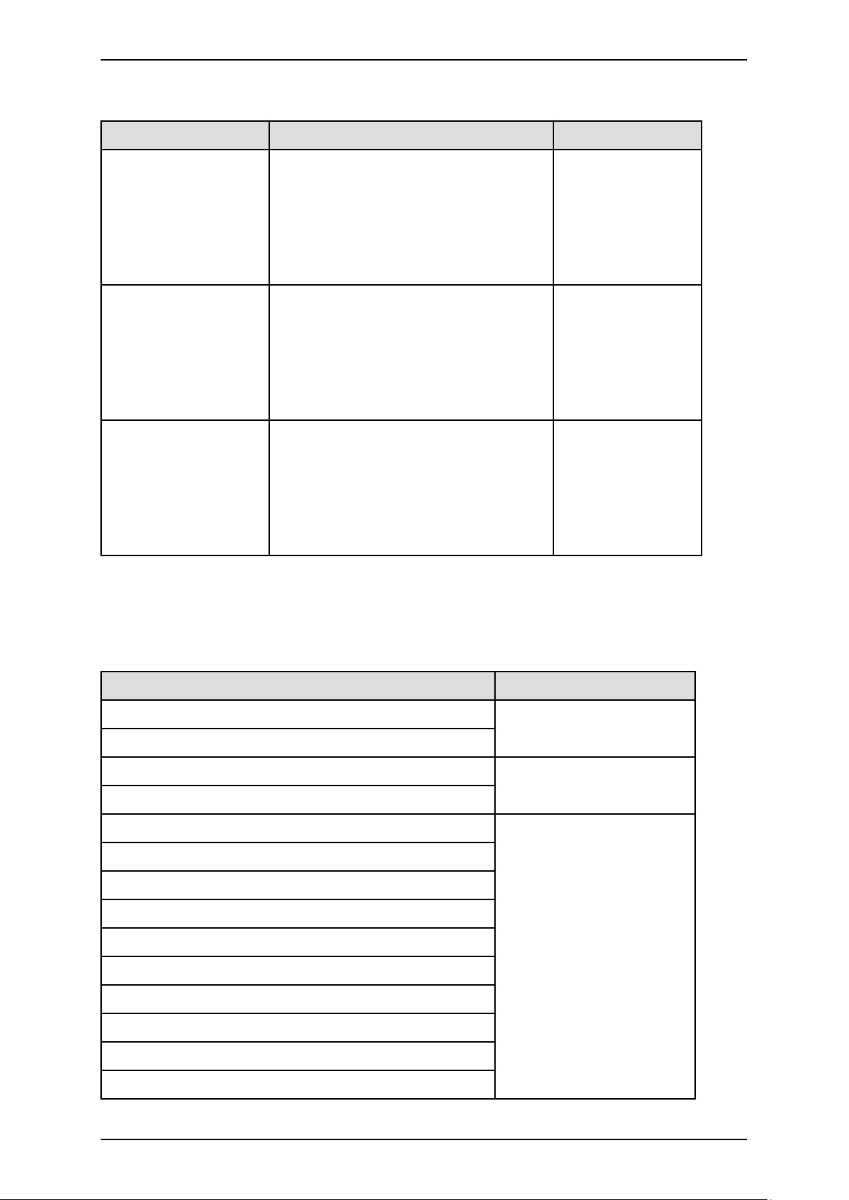
Title Description Manual code
MegaRAID SAS Software Provides technical information on using array
controllers. Refer to the manual from the SVSDVD2 supplied with the product or from the
following URL:
The Fujitsu Technology Solutions manuals server
http://manuals.ts.fujitsu.com
MegaRAID SAS Device
Driver Installation
Provides technical information on using array
controllers. Refer to the manual from the SVSDVD2 supplied with the product or from the
following URL:
The Fujitsu Technology Solutions manuals server
http://manuals.ts.fujitsu.com
Modular RAID Controller
Installation Guide
Provides technical information on using array
controllers. Refer to the manual from the SVSDVD2 supplied with the product or from the
following URL:
The Fujitsu Technology Solutions manuals server
http://manuals.ts.fujitsu.com
None
None
None
Abbreviations
This manual uses the following product name abbreviations.
Formal product name Abbreviation
Red Hat® Enterprise Linux® 5 (for Intel 64) Linux
Red Hat® Enterprise Linux® 5 (for x86)
Red Hat® Enterprise Linux® 6 (for Intel 64) Linux
Red Hat® Enterprise Linux® 6 (for x86)
Microsoft® Windows Server® 2003, Standard Edition Windows
Microsoft® Windows Server® 2003, Enterprise Edition
Microsoft® Windows Server® 2003, Datacenter Edition
Microsoft® Windows Server® 2003, Standard x64 Edition
Microsoft® Windows Server® 2003, Enterprise x64 Edition
Microsoft® Windows Server® 2003, Datacenter x64 Edition
RHEL5, RHEL
RHEL6, RHEL
Windows Server 2003
Microsoft® Windows Server® 2003 R2, Standard Edition
Microsoft® Windows Server® 2003 R2, Enterprise Edition
Microsoft® Windows Server® 2003 R2, Datacenter Edition
Microsoft® Windows Server® 2003 R2, Standard x64 Edition
v C122-E110-10EN
Page 8
PRIMEQUEST 1000 Series Tool Reference
Preface
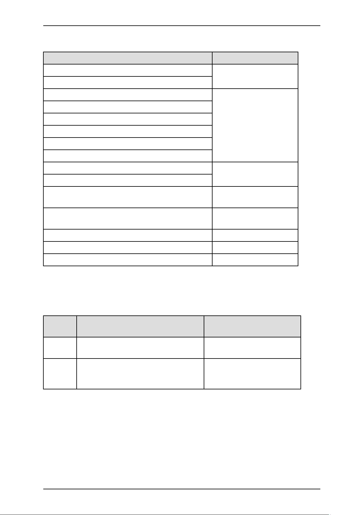
Formal product name Abbreviation
Microsoft® Windows Server® 2003 R2, Enterprise x64 Edition
Microsoft® Windows Server® 2003 R2, Datacenter x64 Edition
Microsoft® Windows Server® 2008 Standard Windows
Microsoft® Windows Server® 2008 Enterprise
Microsoft® Windows Server® 2008 Datacenter
Microsoft® Windows Server® 2008 R2 Standard
Microsoft® Windows Server® 2008 R2 Enterprise
Microsoft® Windows Server® 2008 R2 Datacenter
Microsoft(R) Windows Server(R) 2012 Datacenter Windows
Microsoft(R) Windows Server(R) 2012 Standard
Windows Server 2008
Windows Server 2012
VMware vSphere(R) 4
VMware vSphere(R) 5
VMware(R) ESX(R) 4 ESX, ESX 4.x
VMware(R) ESXi(TM) 5 ESXi, ESXi 5.x
Novell(R) SUSE(R) LINUX Enterprise Server 11 Service Pack 2 SLES11 SP2
VMware, vSphere 4.x, VMware
4.x
VMware, vSphere 5.x, VMware
5.x
Notation
This manual uses the following fonts and symbols to express specific types of information.
Font or
symbol
italics Title of a manual that you should refer to See the PRIMEQUEST 1000 Series
[ ] Window names as well as the names of buttons,
tabs, and drop-down menus in windows are
enclosed in brackets.
Meaning Example
Installation Manual (C122-E107EN).
Click the [OK] button.
Notation for the CLI (command line interface)
The following notation is used for commands.
Command syntax
Command syntax is represented as follows.
- Variables requiring the entry of a value are enclosed in angle brackets < >.
- Optional elements are enclosed in brackets [ ].
- Options for optional keywords are grouped in | (stroke) separated lists enclosed in brackets [ ].
vi C122-E110-10EN
Page 9
PRIMEQUEST 1000 Series Tool Reference
Preface
- Options for required keywords are grouped in | (stroke) separated lists enclosed in braces { }.
Command syntax is written in a box.
Remarks
The command output shown in the PDF manuals may include line feeds at places where there is no line feed symbol
(\ at the end of the line).
Notes on notations
- In this manual, the Management Board and MMB firmware are abbreviated as "MMB."
- In this manual, IOBs and GSPBs (LIOBs and LGSPBs within partitions) are collectively referred to as IO
Units.
- Screenshots contained in this manual may differ from the actual product screen displays.
- The IP addresses, configuration information, and other such information contained in this manual are display
examples and differ from that for actual operation.
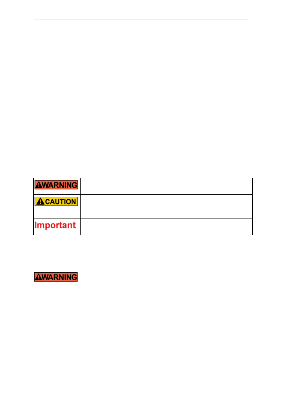
Alert messages
This manual uses the following alert messages to prevent users and bystanders from being injured and to prevent
property damage.
This indicates a hazardous situation that is likely to result in death or serious personal injury
if the user does not perform the procedure correctly.
This indicates a hazardous situation that could result in minor or moderate personal injury
if the user does not perform the procedure correctly. This also indicates that damage to the
product or other property may occur if the user does not perform the procedure correctly.
This indicates information that could help the user use the product more efficiently.
Alert messages in the text
An alert statement follows an alert symbol. An alert statement is indented on both ends to distinguish it from regular
text. Similarly, one space line is inserted before and after the alert statement.
Only Fujitsu certified service engineers should perform the following tasks on this product
and the options provided by Fujitsu. Customers must not perform these tasks under any
circumstances. Otherwise, electric shock, injury, or fire may result.
- Newly installing or moving equipment
- Removing the front, rear, and side covers
- Installing and removing built-in options
- Connecting and disconnecting external interface cables
- Maintenance (repair and periodic diagnosis and maintenance)
The List of important alert items table lists important alert items.
vii C122-E110-10EN
Page 10

PRIMEQUEST 1000 Series Tool Reference
Preface
Product operating environment
This product is a computer intended for use in a computer room environment. For details on the product operating
environment, see the following manual:
PRIMEQUEST 1000 Series Hardware Installation Manual (C122-H004EN)
Note
- If you have a comment or request regarding this manual, or if you find any part of this manual unclear, please
take a moment to share it with us by filling in the form at the following webpage, stating your points
specifically, and sending the form to us:
https://www-s.fujitsu.com/global/contact/computing/PRMQST_feedback.html
- The contents of this manual may be revised without prior notice.
- The PDF file of this manual is intended for display using Adobe® Reader® in single page viewing mode at
100% zoom.
- The PRIMEQUEST 1800E2/1800E model supports only 200 V power supply.
Trademarks
- Microsoft, Windows, and Windows Server are trademarks or registered trademarks of Microsoft Corporation
in the United States and/or other countries.
- Linux is a registered trademark of Linus Torvalds.
- Red Hat, the Shadowman logo and JBoss are registered trademarks of Red Hat, Inc. in the U.S. and other
countries.
- Intel and Xeon are trademarks or registered trademarks of Intel Corporation.
- Ethernet is a registered trademark of Fuji Xerox Co., Ltd. in Japan and is a registered trademark of Xerox
Corp. in the United States and other countries.
- VMware is a trademark or registered trademark of VMware, Inc. in the United States and other countries.
- Novell and SUSE Linux Enterprise Server are trademarks of Novell, Inc.
- Xen is a trademark or registered trademark of Citrix Systems, Inc. or its subsidiaries in the United States and
other countries.
- Other company names and product names are the trademarks or registered trademarks of their respective
owners.
- Trademark indications are omitted for some system and product names in this manual.
Safety Precautions
List of important alert items
This manual does not contain important alert items.
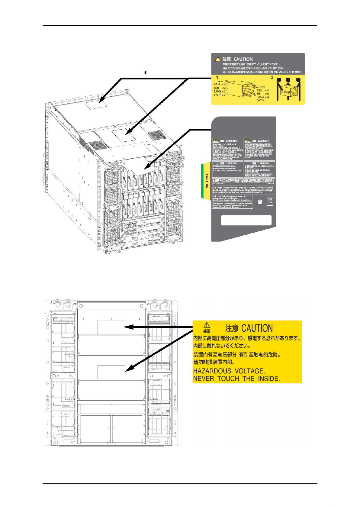
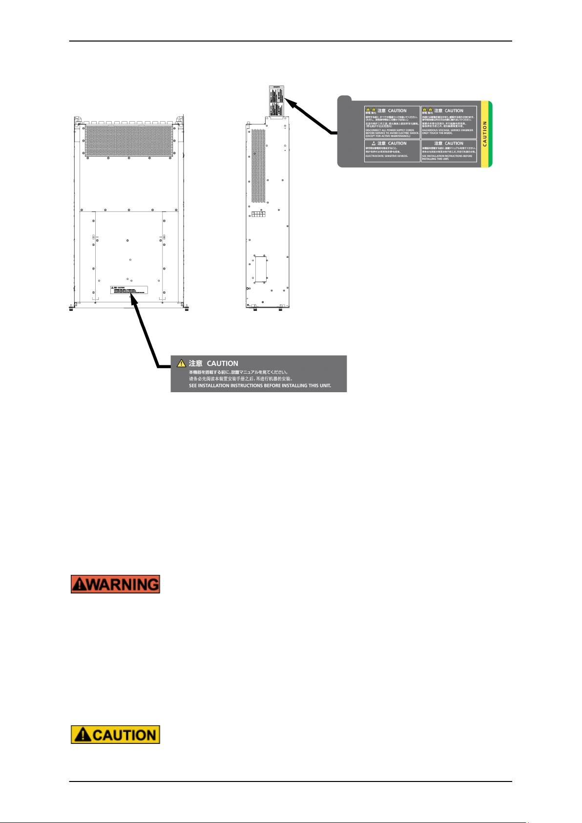
Warning labels
The following warning labels are affixed to this product. These labels are intended for the users of this product.
Never remove the warning labels.
viii C122-E110-10EN
Page 11
PRIMEQUEST 1000 Series Tool Reference
Preface
* The label is affixed at either location.
Warning label location (PRIMEQUEST 1800E2/1800E rear)
Warning label location (PRIMEQUEST 1800E2/1800E rear) (IOBs removed)
ix C122-E110-10EN
Page 12
PRIMEQUEST 1000 Series Tool Reference
Preface
Warning label location (PCI_Box)
Notes on Handling the Product
Adding optional products
For stable operation of the PRIMEQUEST 1000 series server, use only a Fujitsu certified product as an added
option.
Note that the PRIMEQUEST 1000 series server is not guaranteed to operate with any optional product not certified
by Fujitsu.
Maintenance
Only Fujitsu certified service engineers should perform the following tasks on this
product and the options provided by Fujitsu. Customers must not perform these tasks
under any circumstances. Otherwise, electric shock, injury, or fire may result.
- Newly installing or moving equipment
- Removing the front, rear, and side covers
- Installing and removing built-in options
- Connecting and disconnecting external interface cables
- Maintenance (repair and periodic diagnosis and maintenance)
Only Fujitsu certified service engineers should perform the following tasks on this
product and the options provided by Fujitsu. Customers must not perform these tasks
under any circumstances. Otherwise, product failure may result.
x C122-E110-10EN
Page 13

PRIMEQUEST 1000 Series Tool Reference
Preface
- Unpacking an optional Fujitsu product, such as an optional adapter, delivered to
the customer
Modifying or recycling the product
Modifying this product or recycling a secondhand product by overhauling it without prior
approval may result in personal injury to users and/or bystanders or damage to the product
and/or other property.
Note on erasing data from hard disks when disposing of the product or transferring
it
Disposing of this product or transferring it as is may enable third parties to access the data on the hard disk and use
it for unforeseen purposes. To prevent the leakage of confidential information and important data, all of the data
on the hard disk must be erased before disposal or transfer of the product.
However, it can be difficult to completely erase all of the data from the hard disk. Simply initializing (reformatting)
the hard disk or deleting files on the operating system is insufficient to erase the data, even though the data appears
at a glance to have been erased. This type of operation only makes it impossible to access the data from the operating
system. Malicious third parties can restore this data.
If you save your confidential information or other important data on the hard disk, you should completely erase the
data, instead of simply carrying out the aforementioned operation, to prevent the data from being restored.
To prevent important data on the hard disk from being leaked when the product is disposed of or transferred, you
will need to take care to erase all the data recorded on the hard disk on your own responsibility.
Furthermore, if a software license agreement restricts the transfer of the software (operating system and application
software) on the hard disk in the server or other product to a third party, transferring the product without deleting
the software from the hard disk may violate the agreement. Adequate verification from this point of view is also
necessary.
Support and service
SupportDesk (available only in Japan, for a fee)
For stable system operation, we recommend concluding our SupportDesk agreement, which provides a maintenance
and operation support service. SupportDesk agreement customers receive a same-day response service for hardware
problems. They are eligible for regular checkups, remote notification of potential-failure predictions, and
information on system problems. Moreover, they can avail themselves of other services such as troubleshooting
support by phone for hardware and software problems, and access to operation support information from a dedicated
website for our customers. For details, see "Product support" on the SupportDesk homepage (http://jp.fujitsu.com/
solutions/support/sdk/index.html).
Product and service inquiries
For all product use and technical inquiries, contact the distributor where you purchased your product, or a Fujitsu
sales representative or systems engineer (SE). If you do not know the appropriate contact address for inquiries about
the PRIMEQUEST 1000 series, use the Fujitsu contact line.
Fujitsu contact line
We accept Web inquiries. For details, visit our website:
xi C122-E110-10EN
Page 14

PRIMEQUEST 1000 Series Tool Reference
Preface
https://www-s.fujitsu.com/global/contact/computing/PRMQST_feedback.html
Warranty
If a component failure occurs during the warranty period, we will repair it free of charge in accordance with the
terms of the warranty agreement. For details, see the warranty.
Before requesting a repair
If a problem occurs with the product, confirm the problem by referring to 11.2 Troubleshooting in the
PRIMEQUEST 1000 Series Administration Manual (C122-E108EN). If the error recurs, contact your sales
representative or a field engineer. Confirm the model name and serial number shown on the label affixed to the
right front of the device and report it. Also check any other required items beforehand according to 11.2
Troubleshooting in the PRIMEQUEST 1000 Series Administration Manual (C122-E108EN). The system settings
saved by the customer will be used during maintenance.
Revision History
Edition Date Revised location (type) (*) Description
01 2010-02-09 - -
02 2010-03-12 All pages
03 2010-08-20 All pages
04 2011-04-28 All pages
05 2011-05-31 All pages
06 2011-12-20 All pages
07 2012-04-03 Chapter 5 Added items about SR-IOV
Incorporated differences in Errata and
Addenda (C122-E119-01EN)
Incorporated differences in Errata and
Addenda (C122-E119-02EN to C122E119-10EN)
- Added items about 1800E2
- Incorporated differences in
Errata and Addenda (C122E119-11EN to C122E119-18EN)
Incorporated differences in Errata and
Addenda (C122- E119-19EN)
Incorporated differences in Errata and
Addenda (C122- E119-20EN to C122E119-24EN)
08 2013-01-25 All pages
- Incorporated differences in
Errata and Addenda (C122E119-27EN to C122E119-30EN)
- Added items about Windows
Server 2012
- Applied changes to DIMM
capacity
xii C122-E110-10EN
Page 15

PRIMEQUEST 1000 Series Tool Reference
Preface
Edition Date Revised location (type) (*) Description
- Updated descriptions about
09 2013-07-02 Chapter 5
[Configure Memory] menu
- Added Boot order after GSPB
replacement
10 2013-11-19 Chapter 1
Updated descriptions about [Schedule
List] window
* Chapter, section, and item numbers in the "Revised location" column refer to those in the latest edition of the
document. However, a number marked with an asterisk (*) denotes a chapter, section, or item in a previous edition
of the document.
This manual shall not be reproduced or copied without the permission of Fujitsu Limited.
Copyright 2010 - 2013 FUJITSU LIMITED
xiii C122-E110-10EN
Page 16

PRIMEQUEST 1000 Series Tool Reference
Preface
xiv C122-E110-10EN
Page 17

PRIMEQUEST 1000 Series Tool Reference
Contents
Contents
CHAPTER 1 MMB Web-UI (Web User Interface) Operations ........................................................................... 1
1.1 Web-UI Menus .......................................................................................................................................... 2
1.1.1 Web-UI menus (Administrator) ............................................................................................................ 2
1.1.2 Web-UI menus (Operator) ................................................................................................................... 8
1.1.3 Web-UI menus (Partition Operator) ................................................................................................... 14
1.1.4 Web-UI menus (User) ........................................................................................................................ 22
1.1.5 Web-UI menus (CE) .......................................................................................................................... 28
1.1.6 Web-UI menus in maintenance mode ............................................................................................... 34
1.1.7 Web-UI menus in maintenance mode (Administrator) ....................................................................... 35
1.1.8 Web-UI menus in maintenance mode (Operator) .............................................................................. 38
1.1.9 Web-UI menus in maintenance mode (Partition Operator) ............................................................... 42
1.1.10 Web-UI menus in maintenance mode (User) .................................................................................. 46
1.1.11 Web-UI menus in maintenance mode (CE) ..................................................................................... 49
1.1.12 Web-UI menus in maintenance mode (maintenance personnel) .................................................... 53
1.2 [System] Menu ........................................................................................................................................ 58
1.2.1 [System Status] window .................................................................................................................... 58
1.2.2 [System Event Log] window .............................................................................................................. 60
1.2.3 [Operation Log] window ..................................................................................................................... 65
1.2.4 [Partition Event Log] window ............................................................................................................. 69
1.2.5 [System Information] window ............................................................................................................. 73
1.2.6 [Firmware Information] window .......................................................................................................... 75
1.2.7 [System Setup] window ..................................................................................................................... 77
1.2.8 [System Power Control] window ........................................................................................................ 79
1.2.9 [LEDs] window ................................................................................................................................... 81
1.2.10 [Power Supply] window ................................................................................................................... 82
1.2.11 [Fans] window .................................................................................................................................. 84
1.2.12 [Temperature] window ..................................................................................................................... 86
1.2.13 [SB] menu ........................................................................................................................................ 87
1.2.14 [IOB] menu ...................................................................................................................................... 96
1.2.15 [GSPB] menu ................................................................................................................................. 100
1.2.16 [SASU] menu ................................................................................................................................. 103
1.2.17 [PCI_Box] menu ............................................................................................................................ 106
1.2.18 [Other Boards] menu ..................................................................................................................... 112
1.2.19 [MMB] menu .................................................................................................................................. 114
1.3 [Partition] Menu ..................................................................................................................................... 117
1.3.1 [Power Control] window ................................................................................................................... 117
1.3.2 [Schedule] menu .............................................................................................................................. 122
1.3.3 [DVD Switch] window ...................................................................................................................... 129
1.3.4 [Partition Configuration] window ...................................................................................................... 132
1.3.5 [Reserved SB Configuration] window .............................................................................................. 139
1.3.6 [Console Redirection Setup] window ............................................................................................... 141
1.3.7 [Partition#x] menu ............................................................................................................................ 145
1.4 [User Administration] Menu .................................................................................................................. 153
1.4.1 [User List] window ........................................................................................................................... 153
1.4.2 [Change Password] window ............................................................................................................ 158
1.4.3 [Who] window .................................................................................................................................. 159
1.5 [Network Configuration] Menu .............................................................................................................. 161
1.5.1 [Date/Time] window ......................................................................................................................... 161
1.5.2 [Network Interface] window ............................................................................................................. 164
1.5.3 [Management LAN Port Configuration] window .............................................................................. 171
1.5.4 [Network Protocols] window ............................................................................................................ 173
1.5.5 [Refresh Rate] window .................................................................................................................... 176
1.5.6 [SNMP Configuration] menu ............................................................................................................ 177
1.5.7 [SSL] menu ...................................................................................................................................... 183
1.5.8 [SSH] menu ..................................................................................................................................... 190
1.5.9 [Remote Server Management] window ........................................................................................... 192
xv C122-E110-10EN
Page 18

PRIMEQUEST 1000 Series Tool Reference
Contents
1.5.10 [Access Control] window ............................................................................................................... 195
1.5.11 [Alarm E-Mail] window ................................................................................................................... 199
1.6 [Maintenance] Menu ............................................................................................................................. 204
1.6.1 [Firmware Update] menu ................................................................................................................. 204
1.6.2 [Backup/Restore Configuration] menu ............................................................................................ 205
1.6.3 [Maintenance Wizard] window ......................................................................................................... 209
1.6.4 [REMCS] menu ................................................................................................................................ 209
CHAPTER 2 MMB CLI (Command Line Interface) Operations ..................................................................... 211
2.1 Basic Operations with the CLI .............................................................................................................. 212
2.1.1 Access to the CLI via the serial interface ........................................................................................ 212
2.1.2 Access via the management LAN interface .................................................................................... 212
2.1.3 CLI command list ............................................................................................................................. 212
2.2 Setting Commands ............................................................................................................................... 227
2.2.1 add partition ..................................................................................................................................... 227
2.2.2 clear access_control ........................................................................................................................ 229
2.2.3 clear ssh_key ................................................................................................................................... 229
2.2.4 download ssh_key ........................................................................................................................... 230
2.2.5 power off .......................................................................................................................................... 230
2.2.6 power on .......................................................................................................................................... 232
2.2.7 reset ................................................................................................................................................. 233
2.2.8 nmi ................................................................................................................................................... 234
2.2.9 remove partition ............................................................................................................................... 235
2.2.10 set active_mmb ............................................................................................................................. 236
2.2.11 set date .......................................................................................................................................... 237
2.2.12 set gateway ................................................................................................................................... 238
2.2.13 set gateway_ipv6 ........................................................................................................................... 238
2.2.14 set hostname ................................................................................................................................. 239
2.2.15 set http ........................................................................................................................................... 240
2.2.16 set http_port ................................................................................................................................... 240
2.2.17 set https ......................................................................................................................................... 241
2.2.18 set https_port ................................................................................................................................. 241
2.2.19 set ip .............................................................................................................................................. 242
2.2.20 set ipv6 .......................................................................................................................................... 242
2.2.21 set maintenance_ip ....................................................................................................................... 243
2.2.22 set partition home .......................................................................................................................... 244
2.2.23 set partition mirror_mode ............................................................................................................... 245
2.2.24 set partition name .......................................................................................................................... 247
2.2.25 set ssh ........................................................................................................................................... 248
2.2.26 set ssh_port ................................................................................................................................... 249
2.2.27 set telnet ........................................................................................................................................ 249
2.2.28 set telnet_port ................................................................................................................................ 250
2.2.29 set timezone .................................................................................................................................. 250
2.3 Display Commands ............................................................................................................................... 252
2.3.1 show access_control ....................................................................................................................... 252
2.3.2 show active_mmb ............................................................................................................................ 253
2.3.3 show date ........................................................................................................................................ 253
2.3.4 show exit_code ................................................................................................................................ 254
2.3.5 show partition configuration ............................................................................................................. 254
2.3.6 show partition home ........................................................................................................................ 256
2.3.7 show partition name ........................................................................................................................ 257
2.3.8 show partition mirror_mode ............................................................................................................. 257
2.3.9 show timezone ................................................................................................................................. 258
2.3.10 show gateway ................................................................................................................................ 258
2.3.11 showgateway_ipv6 ........................................................................................................................ 259
2.3.12 show http ....................................................................................................................................... 259
2.3.13 show http_port ............................................................................................................................... 260
2.3.14 show https ..................................................................................................................................... 260
xvi C122-E110-10EN
Page 19

PRIMEQUEST 1000 Series Tool Reference
Contents
2.3.15 show https_port ............................................................................................................................. 260
2.3.16 show ip .......................................................................................................................................... 261
2.3.17 showipv6 ........................................................................................................................................ 261
2.3.18 show hostname ............................................................................................................................. 262
2.3.19 show maintenance_ip .................................................................................................................... 262
2.3.20 show ssh ........................................................................................................................................ 263
2.3.21 show ssh_port ............................................................................................................................... 263
2.3.22 show telnet .................................................................................................................................... 263
2.3.23 show telnet_port ............................................................................................................................ 264
2.3.24 show network ................................................................................................................................. 264
2.3.25 show ntpq ...................................................................................................................................... 265
2.3.26 who ................................................................................................................................................ 267
2.3.27 help ................................................................................................................................................ 268
2.3.28 netck traceroute ............................................................................................................................. 273
2.3.29 netck arptbl .................................................................................................................................... 273
2.3.30 netck arping ................................................................................................................................... 274
2.3.31 netck ifconfig .................................................................................................................................. 275
2.3.32 netck stat ....................................................................................................................................... 275
2.4 Update Commands ............................................................................................................................... 277
2.4.1 update ALL ...................................................................................................................................... 277
2.4.2 show update_status ......................................................................................................................... 278
2.5 Other Commands ................................................................................................................................. 280
2.5.1 exit ................................................................................................................................................... 280
2.5.2 passwd ............................................................................................................................................ 280
2.5.3 ping .................................................................................................................................................. 281
CHAPTER 3 PSA Web-UI (Web User Interface) Operations ........................................................................ 283
3.1 Basic PSA Operations .......................................................................................................................... 284
3.2 PSA Web-UI Menus .............................................................................................................................. 286
3.2.1 PSA Web-UI menus (Administrator) ................................................................................................ 286
3.2.2 PSA Web-UI menus (Operator) ....................................................................................................... 287
3.2.3 PSA Web-UI menus (Partition Operator) ......................................................................................... 288
3.2.4 PSA Web-UI menus (User) ............................................................................................................. 290
3.2.5 PSA Web-UI menus (CE) ................................................................................................................ 291
3.3 [Partition Information] Window .............................................................................................................. 293
3.4 [CPUs] Window ..................................................................................................................................... 295
3.5 [DIMMs] Window ................................................................................................................................... 296
3.6 [PCI Devices] Window .......................................................................................................................... 297
3.6.1 [Ethernet Controller] window ........................................................................................................... 298
3.6.2 [Storage Controller] window ............................................................................................................ 303
3.6.3 [RAID Controller] window ................................................................................................................ 307
3.6.4 [Fibre Channel] window ................................................................................................................... 309
3.7 [Network] Menu ..................................................................................................................................... 315
3.7.1 [IPv4 Interfaces] window .................................................................................................................. 315
3.7.2 [IPv6 Interfaces] window .................................................................................................................. 317
3.8 [Hard Disks] Window ............................................................................................................................ 320
3.9 [Hardware Inventory] Window ............................................................................................................... 322
3.10 [Agent Log] Window ............................................................................................................................ 324
3.10.1 [Agent Log Filtering Condition] window ......................................................................................... 326
3.11 [Export List] Window ........................................................................................................................... 330
3.11.1 [Export] window ............................................................................................................................. 332
3.12 [PSA Logs Download] Window ........................................................................................................... 335
3.12.1 [PSA Logs Download] window ..................................................................................................... 336
3.12.2 [PSA Logs Download -Status-] window ......................................................................................... 337
3.12.3 [PSA Logs Download -Result-] window ......................................................................................... 339
CHAPTER 4 PSA CLI (Command Line Interface) Operations ....................................................................... 341
4.1 Basic Operations with the CLI .............................................................................................................. 342
xvii C122-E110-10EN
Page 20

PRIMEQUEST 1000 Series Tool Reference
Contents
4.1.1 CLI command list ............................................................................................................................. 342
4.2 Disk Management Command (diskctrl) ................................................................................................. 344
4.3 PSA Start/Stop Command (y30FJSVpsa) ............................................................................................ 349
4.4 Command for Collecting PSA Data for Investigation (getopsa) ............................................................ 351
4.5 Filter Definition Update Commands (fltcpy, fltupdate) .......................................................................... 352
4.6 Local Partition Number Acquisition Command (getpartid) .................................................................... 355
4.7 Serial Number Acquisition Command (getserialno) .............................................................................. 356
4.8 SNMP Security Setting Command (setsnmpsec) ................................................................................. 357
4.9 Firmware Information Acquisition Command (getfwinfo) ...................................................................... 358
4.10 PCI Card Operation Command (fjpciswap) ........................................................................................ 360
4.11 Firewall Setting Command for the Management LAN Interface (setmlanfw.sh) ................................. 363
4.12 PSA-MMB Communication LAN Setting Command (setpsalan) ......................................................... 367
CHAPTER 5 UEFI Menu Operations ............................................................................................................. 369
5.1 Screen Transitions (from the Boot Manager Front Page) ..................................................................... 370
5.2 Boot Manager Front Page .................................................................................................................... 375
5.2.1 Screen areas ................................................................................................................................... 375
5.3 [Continue] Menu ................................................................................................................................... 378
5.4 [Boot Manager] Menu ........................................................................................................................... 379
5.4.1 Boot options ..................................................................................................................................... 379
5.4.2 Overview of UEFI boot specifications .............................................................................................. 381
5.4.3 Overview of legacy BIOS boot specifications .................................................................................. 387
5.4.4 Boot process .................................................................................................................................... 392
5.5 [Device Manager] Menu ........................................................................................................................ 398
5.5.1 [Configure I/O Space Assignment] menu ........................................................................................ 400
5.5.2 [Configure LAN Remote Boot] menu ............................................................................................... 405
5.5.3 [Configure CPU] menu .................................................................................................................... 413
5.5.4 [Configure PCI Bus Padding] menu ................................................................................................ 418
5.5.5 [iSCSI Configuration] menu ............................................................................................................. 422
5.5.6 [Configure Memory] menu .............................................................................................................. 428
5.5.7 [Configure SR-IOV] menu ................................................................................................................ 431
5.6 [Boot Maintenance Manager] Menu ...................................................................................................... 436
5.6.1 [Boot Options] menu ........................................................................................................................ 437
5.6.2 [Boot From File] menu ..................................................................................................................... 490
5.6.3 [Set Boot Delay Time] menu ............................................................................................................ 494
5.7 Device Path .......................................................................................................................................... 499
5.7.1 Device path parameters .................................................................................................................. 499
5.7.2 Identifying the device path ............................................................................................................... 500
CHAPTER 6 UEFI Command Operations ..................................................................................................... 507
6.1 UEFI Shell and UEFI Commands ......................................................................................................... 508
6.1.1 Automatic startup file ....................................................................................................................... 508
6.1.2 UEFI shell command syntax ............................................................................................................ 508
6.1.3 Output redirection ............................................................................................................................ 509
6.1.4 UEFI shell command list .................................................................................................................. 510
APPENDIX A Lists of Settings ....................................................................................................................... 513
A.1 MMB Web-UI Settings .......................................................................................................................... 514
A.1.1 Setting items in the [System Event Log Filtering Condition] window .............................................. 514
A.1.2 Setting items in the [Operation Log Filtering Condition] window ..................................................... 515
A.1.3 Setting items in the [System Information] window ........................................................................... 516
A.1.4 Setting items in the [System Setup] window ................................................................................... 517
A.1.5 Setting items in the [System Power Control] window ...................................................................... 517
A.1.6 Setting items in the [Power Control] window ................................................................................... 518
A.1.7 Setting items in the [Schedule Control] window .............................................................................. 518
A.1.8 Setting items in the [Add Schedule]/[Edit Schedule] window .......................................................... 519
A.1.9 Setting items in the [Partition Configuration] window ...................................................................... 519
A.1.10 Setting items in the [Console Redirection Setup] window ............................................................. 520
A.1.11 Setting items in the [ASR Control] window .................................................................................... 520
xviii C122-E110-10EN
Page 21

PRIMEQUEST 1000 Series Tool Reference
Contents
A.1.12 Setting items in the [Console Redirection] window ....................................................................... 521
A.1.13 Setting items in the [Mode] window ............................................................................................... 521
A.1.14 Setting items in the [Add User]/[Edit User] window ....................................................................... 521
A.1.15 Setting items in the [Date/Time] window ....................................................................................... 522
A.1.16 Setting items in the [Network Interface] window ........................................................................... 523
A.1.17 Setting items in the [Management LAN Port Configuration] window ............................................ 525
A.1.18 Setting items in the [Network Protocols] window .......................................................................... 525
A.1.19 Setting items in the [Refresh Rate] window .................................................................................. 526
A.1.20 Setting items in the [SNMP Community] window .......................................................................... 527
A.1.21 Setting items in the [SNMP Trap] window ..................................................................................... 527
A.1.22 Setting items in the [SNMP v3 Configuration] window .................................................................. 528
A.1.23 Setting items in the [Create CSR] window .................................................................................... 529
A.1.24 Setting items in the [Create Selfsigned Certificate] window .......................................................... 529
A.1.25 Setting items in the [Edit User] window ......................................................................................... 530
A.1.26 Setting items in the [Add Filter]/[Edit Filter] window ...................................................................... 531
A.1.27 Setting items in the [Alarm E-Mail] window ................................................................................... 531
A.1.28 Setting items in the [Alarm E-Mail Filtering Condition] window ..................................................... 532
A.2 PSA settings ......................................................................................................................................... 533
A.2.1 Setting items in the [Agent Log Filtering Condition] window ........................................................... 533
A.3 UEFI settings ........................................................................................................................................ 534
A.3.1 Setting items in the [Configure I/O Space Assignment] window ..................................................... 534
A.3.2 Setting items in the [Configure LAN Remote Boot] window ............................................................ 534
A.3.3 Setting items in the [Configure CPU] window ................................................................................. 534
A.4 BMC settings ........................................................................................................................................ 536
A.4.1 Setting items in the [Languages] window ........................................................................................ 536
A.4.2 Setting items in the [Preferences] window ...................................................................................... 536
Index ............................................................................................................................................................... 539
xix C122-E110-10EN
Page 22

PRIMEQUEST 1000 Series Tool Reference
Figures
Figures
Warning label location (PRIMEQUEST 1800E2/1800E rear) ............................................................................. ix
Warning label location (PRIMEQUEST 1800E2/1800E rear) (IOBs removed) .................................................. ix
Warning label location (PCI_Box) ....................................................................................................................... x
FIGURE 1.1 [System Status] window .............................................................................................................. 58
FIGURE 1.2 [System Event Log] window ........................................................................................................ 60
FIGURE 1.3 [System Event Log (Collect)] window .......................................................................................... 62
FIGURE 1.4 [System Event Log Filtering Condition] window .......................................................................... 63
FIGURE 1.5 [Operation Log] window ............................................................................................................... 66
FIGURE 1.6 [Operation Log Filtering Condition] window ................................................................................. 68
FIGURE 1.7 [Partition Event Log] window ....................................................................................................... 70
FIGURE 1.8 [Partition Event Log Filtering Condition] window ......................................................................... 72
FIGURE 1.9 [System Information] window ...................................................................................................... 73
FIGURE 1.10 [Firmware Information] window ................................................................................................. 75
FIGURE 1.11 [System Setup] window ............................................................................................................. 77
FIGURE 1.12 [System Power Control] window ................................................................................................ 79
FIGURE 1.13 [LEDs] window ........................................................................................................................... 81
FIGURE 1.14 [Power Supply] window ............................................................................................................. 83
FIGURE 1.15 [Fans] window ........................................................................................................................... 85
FIGURE 1.16 [Temperature] window ............................................................................................................... 87
FIGURE 1.17 [SB#x] window (1) ..................................................................................................................... 88
FIGURE 1.18 [SB#x] window (2) ..................................................................................................................... 89
FIGURE 1.19 [SB#x] window (3) ..................................................................................................................... 89
FIGURE 1.20 [SB#x Status Clear] window (Message display) ........................................................................ 95
FIGURE 1.21 [SB#x] window (when no CPUs or DIMMs are mounted) .......................................................... 96
FIGURE 1.22 [IOB#x] window (1) .................................................................................................................... 97
FIGURE 1.23 [IOB#x] window (2) .................................................................................................................... 97
FIGURE 1.24 [GSPB#x] window (1) .............................................................................................................. 100
FIGURE 1.25 [GSPB#x] window (2) .............................................................................................................. 101
FIGURE 1.26 [SASU#x] window .................................................................................................................... 104
FIGURE 1.27 [PCI_Box#x] window (1) .......................................................................................................... 107
FIGURE 1.28 [PCI_Box#x] window (2) .......................................................................................................... 107
FIGURE 1.29 [PCI_Box#x] window (3) .......................................................................................................... 108
FIGURE 1.30 [DVDB] window ....................................................................................................................... 112
FIGURE 1.31 [MMB#x] window ..................................................................................................................... 114
FIGURE 1.32 [Power Control] window ........................................................................................................... 117
FIGURE 1.33 [Power Control] window (grayed out) ...................................................................................... 118
FIGURE 1.34 Error display in the [Power Control] window ............................................................................ 121
FIGURE 1.35 [Schedule Control] window ...................................................................................................... 123
FIGURE 1.36 [Schedule List] window ............................................................................................................ 124
FIGURE 1.37 [Add Schedule] window ........................................................................................................... 127
FIGURE 1.38 [DVD Switch] window .............................................................................................................. 129
FIGURE 1.39 [Partition Configuration] window .............................................................................................. 132
FIGURE 1.40 [Add SB/IOB/GSPB to Partition] window ................................................................................. 134
FIGURE 1.41 [Remove SB/IOB/GSPB from Partition] window ...................................................................... 136
FIGURE 1.42 [Partition Home] window .......................................................................................................... 138
FIGURE 1.43 [Reserved SB Configuration] window ...................................................................................... 139
FIGURE 1.44 [IPv4 Console Redirection Setup] window .............................................................................. 142
FIGURE 1.45 [IPv6 Console Redirection Setup] window .............................................................................. 144
FIGURE 1.46 [Information] window ............................................................................................................... 146
FIGURE 1.47 [ASR (Automatic Server Restart) Control] window .................................................................. 147
FIGURE 1.48 [Console Redirection] window ................................................................................................. 149
FIGURE 1.49 [Mode] window ........................................................................................................................ 150
FIGURE 1.50 [User List] window ................................................................................................................... 153
FIGURE 1.51 [Add User] window .................................................................................................................. 155
FIGURE 1.52 [Edit User] window ................................................................................................................... 156
FIGURE 1.53 [Change Password] window .................................................................................................... 158
xx C122-E110-10EN
Page 23

PRIMEQUEST 1000 Series Tool Reference
Figures
FIGURE 1.54 [Who] window .......................................................................................................................... 159
FIGURE 1.55 [Date/Time] window ................................................................................................................. 161
FIGURE 1.56 [IPv4 Interface] window (1) ...................................................................................................... 165
FIGURE 1.57 [IPv4 Interface] window (2) ...................................................................................................... 165
FIGURE 1.58 [IPv6 Interface] window (1) ...................................................................................................... 168
FIGURE 1.59 [IPv6 Interface] window (2) ...................................................................................................... 169
FIGURE 1.60 [Management LAN Port Configuration] window ...................................................................... 172
FIGURE 1.61 [Network Protocols] window .................................................................................................... 173
FIGURE 1.62 [Refresh Rate] window ............................................................................................................ 176
FIGURE 1.63 [SNMP Community] window .................................................................................................... 178
FIGURE 1.64 [SNMP Trap] window ............................................................................................................... 180
FIGURE 1.65 [SNMP v3 Configuration] window ............................................................................................ 182
FIGURE 1.66 [Create CSR] window .............................................................................................................. 184
FIGURE 1.67 Confirmation dialog box ........................................................................................................... 185
FIGURE 1.68 [Export Key/CSR] window ....................................................................................................... 186
FIGURE 1.69 [Import Certificate] window ...................................................................................................... 188
FIGURE 1.70 [Create Selfsigned Certificate] window .................................................................................... 189
FIGURE 1.71 [Create SSH Server Key] window ........................................................................................... 191
FIGURE 1.72 [Remote Server Management] window ................................................................................... 192
FIGURE 1.73 [Edit User] window ................................................................................................................... 194
FIGURE 1.74 [Access Control] window ......................................................................................................... 196
FIGURE 1.75 [Add Filter] window .................................................................................................................. 198
FIGURE 1.76 [Alarm E-Mail] window ............................................................................................................. 200
FIGURE 1.77 [Alarm E-Mail Filtering Condition] window ............................................................................... 202
FIGURE 1.78 [Unified Firmware Update] window .......................................................................................... 204
FIGURE 1.79 Backup/Restore MMB Configuration window .......................................................................... 205
FIGURE 1.80 [Backup BIOS Configuration] window ..................................................................................... 207
FIGURE 1.81 [Restore BIOS Configuration] window (1) ............................................................................... 208
FIGURE 1.82 [Restore BIOS Configuration] window (2) ............................................................................... 208
FIGURE 3.1 [Partition Information] window (Linux) ....................................................................................... 293
FIGURE 3.2 [Partition Information] window (Windows) ................................................................................. 293
FIGURE 3.3 [CPUs] window .......................................................................................................................... 295
FIGURE 3.4 [DIMMs] window ........................................................................................................................ 296
FIGURE 3.5 [PCI Devices] window ................................................................................................................ 297
FIGURE 3.6 [Ethernet Controller] window ..................................................................................................... 298
FIGURE 3.7 [Ethernet Controller] window (progress bar displayed) ............................................................. 299
FIGURE 3.8 [Storage Controller] window ...................................................................................................... 304
FIGURE 3.9 [RAID Controller] window .......................................................................................................... 308
FIGURE 3.10 [Fibre Channel] window ........................................................................................................... 310
FIGURE 3.11 [IPv4 Interfaces] window ......................................................................................................... 315
FIGURE 3.12 [IPv4 Interfaces] window (progress bar displayed) .................................................................. 316
FIGURE 3.13 [IPv6 Interfaces] window ......................................................................................................... 317
FIGURE 3.14 [IPv6 Interfaces] window (progress bar displayed) .................................................................. 318
FIGURE 3.15 [Hard Disks] window ................................................................................................................ 321
FIGURE 3.16 [Hardware Inventory] window .................................................................................................. 322
FIGURE 3.17 [Agent Log] window ................................................................................................................. 324
FIGURE 3.18 [Agent Log Filtering Condition] window ................................................................................... 327
FIGURE 3.19 [Export List] window ................................................................................................................ 330
FIGURE 3.20 [Export] window ....................................................................................................................... 333
FIGURE 3.21 [PSA Logs Download] window (Linux) .................................................................................... 336
FIGURE 3.22 [PSA Logs Download] window (Windows) .............................................................................. 337
FIGURE 3.23 [PSA Logs Download -Status-] window (Linux) ....................................................................... 338
FIGURE 3.24 [PSA Logs Download -Result-] window (Linux) ....................................................................... 339
FIGURE 4.1 Output file format ....................................................................................................................... 359
FIGURE 5.1 Transitions from the Boot Manager front page .......................................................................... 370
FIGURE 5.2 Transitions from the [Boot Maintenance Manager] menu ......................................................... 371
FIGURE 5.3 Transitions from the [Boot Options] menu (1/3) ........................................................................ 372
FIGURE 5.4 Transitions from the [Boot Options] menu (2/3) ........................................................................ 373
xxi C122-E110-10EN
Page 24

PRIMEQUEST 1000 Series Tool Reference
Figures
FIGURE 5.5 Transitions from the [Boot Options] menu (3/3) ........................................................................ 374
FIGURE 5.6 Example of display of the Boot Manager front page ................................................................. 375
FIGURE 5.7 Screen areas on the Boot Manager front page ......................................................................... 376
FIGURE 5.8 Example of display of the [Boot Manager] menu ....................................................................... 379
FIGURE 5.9 Boot options in Boot Manager ................................................................................................... 382
FIGURE 5.10 Boot Manager after a change in the boot order ....................................................................... 383
FIGURE 5.11 Boot Manager after a boot option is added ............................................................................. 384
FIGURE 5.12 Boot Manager after a boot option is deleted ........................................................................... 385
FIGURE 5.13 Boot order before GSPB replacement ..................................................................................... 386
FIGURE 5.14 Boot order after GSPB replacement ........................................................................................ 387
FIGURE 5.15 Executing the [Legacy Boot] option ......................................................................................... 388
FIGURE 5.16 Example of display of the [Change Legacy Boot Order] menu ............................................... 389
FIGURE 5.17 Example of display of the [Change Legacy HDD Boot Priority] menu ..................................... 390
FIGURE 5.18 Example of display of the [Change Legacy DVD/CD Boot Priority] menu ............................... 391
FIGURE 5.19 Example of display of the [Change Legacy PXE Boot Priority] menu ..................................... 392
FIGURE 5.20 Example of display of the [Boot Manager] menu ..................................................................... 396
FIGURE 5.21 Example of display of the [Device Manager] menu ................................................................. 398
FIGURE 5.22 Example of display of the [Configure I/O Space Assignment] menu ....................................... 401
FIGURE 5.23 Operation screen for I/O space assignment (1) ...................................................................... 403
FIGURE 5.24 Operation screen for I/O space assignment (2) ...................................................................... 404
FIGURE 5.25 Operation screen for I/O space assignment (3) ...................................................................... 405
FIGURE 5.26 Example of display of the [Configure LAN Remote Boot] menu .............................................. 406
FIGURE 5.27 Operation screen for the PXE boot Enable setting (1) ............................................................ 408
FIGURE 5.28 Operation screen for the PXE boot Enable setting (2) ............................................................ 409
FIGURE 5.29 Operation screen for the PXE boot Enable setting (3) ............................................................ 410
FIGURE 5.30 Example of display of the [Boot Manager] menu ..................................................................... 411
FIGURE 5.31 Example of display of the [iSCSI Configuration] ...................................................................... 412
FIGURE 5.32 Example of display of the [Change Legacy PXE boot Priority] menu ...................................... 413
FIGURE 5.33 Example of display of the [Configure CPU] menu ................................................................... 414
FIGURE 5.34 Display example of the [Configure PCI Bus Padding] menu ................................................... 419
FIGURE 5.35 Screen for operation to allocate the number of buses to the PCI Express slot (1) .................. 420
FIGURE 5.36 Screen for operation to allocate the number of buses to the PCI Express slot (2) .................. 421
FIGURE 5.37 Screen for operation to allocate the number of buses to the PCI Express slot (3) .................. 422
FIGURE 5.38 Example of display of the [iSCSI Configuration] menu ............................................................ 423
FIGURE 5.39 Operation screen for iSCSI environment configuration (1) ...................................................... 424
FIGURE 5.40 Operation screen for iSCSI environment configuration (2) ...................................................... 425
FIGURE 5.41 Example of display of the [Configure Memory] menu .............................................................. 428
FIGURE 5.42 Screen for operation to set the DIMM Self Refresh function (1) .............................................. 430
FIGURE 5.43 Screen for operation to set the DIMM Self Refresh function (2) .............................................. 430
FIGURE 5.44 Screen for operation to set the DIMM Self Refresh function (3) .............................................. 431
FIGURE 5.45 Example of display of the [Configure SR-IOV] menu .............................................................. 432
FIGURE 5.46 Screen for operation to set SR-IOV (1) ................................................................................... 433
FIGURE 5.47 Screen for operation to set SR-IOV (2) ................................................................................... 434
FIGURE 5.48 Screen for operation to set SR-IOV (3) ................................................................................... 435
FIGURE 5.49 [Boot Maintenance Manager] menu ........................................................................................ 436
FIGURE 5.50 [Boot Options] menu ................................................................................................................ 438
FIGURE 5.51 Example of display of the Boot Manager menu ....................................................................... 440
FIGURE 5.52 Example of display of the [Add Boot Option] menu ................................................................. 441
FIGURE 5.53 Device list ................................................................................................................................ 442
FIGURE 5.54 Example of display of the file selection screen ........................................................................ 443
FIGURE 5.55 Screen of the disk where Windows Server 2008 is installed ................................................... 444
FIGURE 5.56 Screen display example of a boot option name change (1) .................................................... 445
FIGURE 5.57 Screen display example of a boot option name change (2) .................................................... 446
FIGURE 5.58 Screen display example of a boot option name change (3) .................................................... 447
FIGURE 5.59 Screen display example of a boot option name change (4) .................................................... 448
FIGURE 5.60 Example of display of the [Boot Manager] menu ..................................................................... 449
FIGURE 5.61 Window that appears when not enough characters were entered .......................................... 450
FIGURE 5.62 Example of display of the [Delete Boot Option] menu ............................................................. 451
xxii C122-E110-10EN
Page 25

PRIMEQUEST 1000 Series Tool Reference
Figures
FIGURE 5.63 [Delete Boot Option] screen (1) ............................................................................................... 452
FIGURE 5.64 [Delete Boot Option] screen (2) ............................................................................................... 453
FIGURE 5.65 [Delete Boot Option] screen (3) ............................................................................................... 454
FIGURE 5.66 [Delete Boot Option] screen (4) ............................................................................................... 455
FIGURE 5.67 [Delete Boot Option] screen (5) ............................................................................................... 456
FIGURE 5.68 [Change Boot Order] menu ..................................................................................................... 457
FIGURE 5.69 Changing the order of priority on the [Change Boot Order] screen (1) ................................... 459
FIGURE 5.70 Changing the order of priority on the [Change Boot Order] screen (2) ................................... 460
FIGURE 5.71 [Change Boot Order] screen after a priority order setting change ........................................... 461
FIGURE 5.72 Example of display of the [Change Legacy Boot Order] menu ............................................... 462
FIGURE 5.73 Changing the order of priority on the [Change Legacy Boot Order] screen (1) ....................... 464
FIGURE 5.74 Changing the order of priority on the [Change Legacy Boot Order] screen (2) ....................... 465
FIGURE 5.75 Changing the order of priority on the [Change Legacy Boot Order] screen (3) ....................... 466
FIGURE 5.76 Changing the order of priority on the [Change Legacy Boot Order] screen (4) ....................... 467
FIGURE 5.77 Example of the [Change Legacy Boot Order] screen display after a setting change .............. 468
FIGURE 5.78 Example of display of the [Change Legacy HDD Boot Priority] menu ..................................... 469
FIGURE 5.79 Changing the order of priority (Change Legacy HDD Boot Priority) (1) .................................. 471
FIGURE 5.80 Changing the order of priority (Change Legacy HDD Boot Priority) (2) .................................. 472
FIGURE 5.81 Changing the order of priority (Change Legacy HDD Boot Priority) (3) .................................. 473
FIGURE 5.82 Changing the order of priority (Change Legacy HDD Boot Priority) (4) .................................. 474
FIGURE 5.83 Example of the [Change Legacy HDD Boot Priority] screen display after a setting change ....
475
FIGURE 5.84 Example of display of the [Change Legacy DVD/CD Boot Priority] menu ............................... 477
FIGURE 5.85 Changing the order of priority (Change Legacy DVD/CD Boot Priority) (1) ............................ 479
FIGURE 5.86 Changing the order of priority (Change Legacy DVD/CD Boot Priority) (2) ............................ 480
FIGURE 5.87 Changing the order of priority (Change Legacy DVD/CD Boot Priority) (3) ............................ 481
FIGURE 5.88 Changing the order of priority (Change Legacy DVD/CD Boot Priority) (4) ............................ 482
FIGURE 5.89 Example of the [Change Legacy DVD/CD Boot Priority] screen display after a setting change ....
483
FIGURE 5.90 Example of display of the [Change Legacy PXE Boot Priority] menu ..................................... 484
FIGURE 5.91 Changing the order of priority (Change Legacy PXE Boot Priority) (1) ................................... 486
FIGURE 5.92 Changing the order of priority (Change Legacy PXE Boot Priority) (2) ................................... 487
FIGURE 5.93 Changing the order of priority (Change Legacy PXE Boot Priority) (3) ................................... 488
FIGURE 5.94 Changing the order of priority (Change Legacy PXE Boot Priority) (4) ................................... 489
FIGURE 5.95 Example of the [Change Legacy PXE Boot Priority] screen display after a setting change ....
490
FIGURE 5.96 Example of display of the [Boot From File] menu .................................................................... 491
FIGURE 5.97 Specifying the boot file (1) ....................................................................................................... 492
FIGURE 5.98 Specifying the boot file (2) ....................................................................................................... 493
FIGURE 5.99 Specifying the boot file (3) ....................................................................................................... 494
FIGURE 5.100 Logo screen ........................................................................................................................... 495
FIGURE 5.101 Example of display of the [Set Boot Delay Time] menu ........................................................ 495
FIGURE 5.102 Changing the logo display time (1) ........................................................................................ 497
FIGURE 5.103 Changing the logo display time (2) ........................................................................................ 498
FIGURE 5.104 Identifying a SAS disk ........................................................................................................... 500
FIGURE 5.105 Relationship of connections between an IOH and SAS disk ................................................. 501
FIGURE 5.106 Relationship between a device path and connections (SAS disk) (1) ................................... 501
FIGURE 5.107 Relationship between a device path and connections (SAS disk) (2) ................................... 502
FIGURE 5.108 Relationship between a device path and connections (SAS disk) (3) ................................... 502
FIGURE 5.109 Relationship between a device path and connections (SAS disk) (4) ................................... 503
FIGURE 5.110 Identifying a disk connected through a Fibre card ................................................................. 503
FIGURE 5.111 Relationship of connections between an IOH and Fibre card ............................................... 503
FIGURE 5.112 Relationship between a device path and connections (Fibre card) ....................................... 504
FIGURE 5.113 Identifying a GigaLAN device ................................................................................................ 504
FIGURE 5.114 Relationship of connections between an IOH and GigaLAN device ..................................... 505
FIGURE 5.115 Relationship between a device path and connections (GigaLAN) ........................................ 505
FIGURE 6.1 Sample screenshot of the UEFI shell immediately after it starts ............................................... 508
xxiii C122-E110-10EN
Page 26

PRIMEQUEST 1000 Series Tool Reference
Tables
Tables
TABLE 1.1 User privileges ................................................................................................................................. 2
TABLE 1.2 Web-UI menus (Administrator) ........................................................................................................ 3
TABLE 1.3 Web-UI menus (Operator) ............................................................................................................... 8
TABLE 1.4 Web-UI menus (Partition Operator) ............................................................................................... 15
TABLE 1.5 Web-UI menus (User) .................................................................................................................... 22
TABLE 1.6 Web-UI menus (CE) ...................................................................................................................... 28
TABLE 1.7 Types of maintenance mode ......................................................................................................... 34
TABLE 1.8 Web-UI menus in maintenance mode (Administrator) ................................................................... 35
TABLE 1.9 Web-UI menus in maintenance mode (Operator) .......................................................................... 39
TABLE 1.10 Web-UI menus in maintenance mode (Partition Operator) ......................................................... 42
TABLE 1.11 Web-UI menus in maintenance mode (User) .............................................................................. 46
TABLE 1.12 Web-UI menus in maintenance mode (CE) ................................................................................. 50
TABLE 1.13 Web-UI menus in maintenance mode (maintenance personnel) ................................................ 54
TABLE 1.14 Unit status and displayed icon ..................................................................................................... 59
TABLE 1.15 Display items in the [System Status] window .............................................................................. 59
TABLE 1.16 Display items in the [System Event Log] window ........................................................................ 60
TABLE 1.17 Buttons in the [System Event Log] window ................................................................................. 61
TABLE 1.18 Setting and display items in the [System Event Log Filtering Condition] window ........................ 63
TABLE 1.19 Buttons in the [System Event Log Filtering Condition] window ................................................... 65
TABLE 1.20 Display items in the [Operation Log] window ............................................................................... 66
TABLE 1.21 Buttons in the [Operation Log] window ........................................................................................ 67
TABLE 1.22 Setting and display items in the [Operation Log Filtering Condition] window .............................. 68
TABLE 1.23 Buttons in the [Operation Log Filtering Condition] window .......................................................... 69
TABLE 1.24 Display items in the [Partition Event Log] window ....................................................................... 70
TABLE 1.25 Buttons in the [Partition Event Log] window ................................................................................ 71
TABLE 1.26 Display and setting items in the [Partition Event Log Filtering Condition] window ...................... 72
TABLE 1.27 Buttons in the [Partition Event Log Filtering Condition] window .................................................. 72
TABLE 1.28 Setting and display items in the [System Information] window .................................................... 74
TABLE 1.29 Buttons in the [System Information] window ................................................................................ 74
TABLE 1.30 Display items in the [Firmware Information] window ................................................................... 75
TABLE 1.31 Setting and display items in the [System Setup] window ............................................................ 77
TABLE 1.32 Buttons in the [System Setup] window ........................................................................................ 78
TABLE 1.33 Setting and display items in the [System Power Control] window ............................................... 80
TABLE 1.34 Buttons in the [System Power Control] window ........................................................................... 80
TABLE 1.35 Setting and display items in the [LEDs] window .......................................................................... 81
TABLE 1.36 Buttons in the [LEDs] window ...................................................................................................... 82
TABLE 1.37 Display items in the [Power Supply] window ............................................................................... 83
TABLE 1.38 Buttons in the [Power Supply] window ........................................................................................ 84
TABLE 1.39 Display items in the [Fans] window ............................................................................................. 85
TABLE 1.40 Buttons in the [Fans] window ....................................................................................................... 86
TABLE 1.41 Display items in the [Temperature] window ................................................................................. 87
TABLE 1.42 Setting and display items in the [SB#x] window .......................................................................... 90
TABLE 1.43 Buttons in the [SB#x] window ...................................................................................................... 94
TABLE 1.44 Setting and display items in the [IOB#x] window ......................................................................... 98
TABLE 1.45 Buttons in the [IOB#x] window ..................................................................................................... 99
TABLE 1.46 Setting and display items in the [GSPB#x] window ................................................................... 101
TABLE 1.47 Buttons in the [GSPB#x] window ............................................................................................... 102
TABLE 1.48 Setting and display items in the [SASU#x] window ................................................................... 104
TABLE 1.49 Buttons in the [SASU#x] window ............................................................................................... 105
TABLE 1.50 Setting and display items in the [PCI_Box#x] window ............................................................... 108
TABLE 1.51 Buttons in the [PCI_Box#x] window ........................................................................................... 111
TABLE 1.52 Display items in the [DVDB] window ......................................................................................... 113
TABLE 1.53 Buttons in the [DVDB] window ................................................................................................... 113
TABLE 1.54 Setting and display items in the [MMB#x] window ..................................................................... 114
TABLE 1.55 Buttons in the [MMB#x] window ................................................................................................ 116
TABLE 1.56 Setting and display items in the [Power Control] window .......................................................... 118
xxiv C122-E110-10EN
Page 27

PRIMEQUEST 1000 Series Tool Reference
Tables
TABLE 1.57 Buttons in the [Power Control] window ...................................................................................... 120
TABLE 1.58 Setting and display items in the [Schedule Control] window ..................................................... 123
TABLE 1.59 Buttons in the [Schedule Control] window ................................................................................. 124
TABLE 1.60 Setting and display items in the [Schedule List] window ........................................................... 125
TABLE 1.61 Buttons in the [Schedule List] window ....................................................................................... 126
TABLE 1.62 Setting and display items in the [Add Schedule] window .......................................................... 127
TABLE 1.63 Buttons in the [Add Schedule] window ...................................................................................... 128
TABLE 1.64 Setting and display items in the [DVD Switch] window .............................................................. 129
TABLE 1.65 Whether a confirmation message appears in maintenance mode ............................................ 130
TABLE 1.66 Buttons in the [DVD Switch] window ......................................................................................... 131
TABLE 1.67 Setting and display items in the [Partition Configuration] window ............................................. 133
TABLE 1.68 Buttons in the [Partition Configuration] window ......................................................................... 133
TABLE 1.69 Setting and display items in the [Add SB/IOB/GSPB to Partition] window ................................ 135
TABLE 1.70 Setting and display items in the [Remove SB/IOB/GSPB from Partition] window ..................... 136
TABLE 1.71 Setting and display items in the [Reserved SB Configuration] window ..................................... 140
TABLE 1.72 Buttons in the [Reserved SB Configuration] window ................................................................. 140
TABLE 1.73 Setting and display items in the [IPv4 Console Redirection Setup] window .............................. 142
TABLE 1.74 Buttons in the [IPv4 Console Redirection Setup] window .......................................................... 143
TABLE 1.75 Setting and display items in the [IPv6 Console Redirection Setup] window .............................. 144
TABLE 1.76 Buttons in the [IPv6 Console Redirection Setup] window .......................................................... 145
TABLE 1.77 Display items in the [Information] window ................................................................................. 146
TABLE 1.78 Setting and display items in the [ASR (Automatic Server Restart) Control] window ................. 148
TABLE 1.79 Buttons in the [ASR (Automatic Server Restart) Control] window ............................................. 148
TABLE 1.80 Setting and display items in the [Console Redirection] window ................................................ 149
TABLE 1.81 Setting and display items in the [Mode] window ........................................................................ 151
TABLE 1.82 Display items in the [User List] window ..................................................................................... 153
TABLE 1.83 Buttons in the [User List] window .............................................................................................. 154
TABLE 1.84 Setting and display items in the [Add User] and [Edit User] windows ....................................... 156
TABLE 1.85 Buttons in the [Add User] and [Edit User] windows ................................................................... 157
TABLE 1.86 Buttons in the [Change Password] window ............................................................................... 158
TABLE 1.87 Display items in the [Who] window ............................................................................................ 159
TABLE 1.88 Setting and display items in the [Date/Time] window ................................................................ 161
TABLE 1.89 Buttons in the [Date/Time] window ............................................................................................ 163
TABLE 1.90 Setting and display items in the [IPv4 Interface] window ........................................................... 165
TABLE 1.91 Buttons in the [IPv4 Interface] window ...................................................................................... 168
TABLE 1.92 Setting and display items in the [IPv6 Interface] window ........................................................... 169
TABLE 1.93 Buttons in the [IPv6 Interface] window ...................................................................................... 171
TABLE 1.94 Setting and display items in the [Management LAN Port Configuration] window ...................... 172
TABLE 1.95 Buttons in the [Management LAN Port Configuration] window .................................................. 173
TABLE 1.96 Setting and display items in the [Network Protocols] window .................................................... 174
TABLE 1.97 Buttons in the [Network Protocols] window ............................................................................... 175
TABLE 1.98 Setting and display items in the [Refresh Rate] window ............................................................ 176
TABLE 1.99 Buttons in the [Refresh Rate] window ....................................................................................... 176
TABLE 1.100 Setting and display items in the [SNMP Community] window ................................................. 178
TABLE 1.101 Buttons in the [SNMP Community] window ............................................................................. 179
TABLE 1.102 Setting and display items in the [SNMP Trap] window ............................................................ 180
TABLE 1.103 Buttons in the [SNMP Trap] window ........................................................................................ 181
TABLE 1.104 Setting and display items in the [SNMP v3 Configuration] window ......................................... 182
TABLE 1.105 Buttons in the [SNMP v3 Configuration] window ..................................................................... 182
TABLE 1.106 Setting and display items in the [Create CSR] window ........................................................... 184
TABLE 1.107 Buttons in the [Create CSR] window ....................................................................................... 185
TABLE 1.108 Buttons in the [Export Key/CSR] window ................................................................................ 187
TABLE 1.109 Buttons in the [Import Certificate] window ............................................................................... 188
TABLE 1.110 Display items in the [Create Selfsigned Certificate] window .................................................... 189
TABLE 1.111 Buttons in the [Create Selfsigned Certificate] window ............................................................. 189
TABLE 1.112 Buttons in the [Create SSH Server Key] window ..................................................................... 191
TABLE 1.113 Display and setting items in the [Remote Server Management] window ................................. 192
TABLE 1.114 Buttons in the [Remote Server Management] window ............................................................ 193
xxv C122-E110-10EN
Page 28

PRIMEQUEST 1000 Series Tool Reference
Tables
TABLE 1.115 Display and setting items in the [Edit User] window ................................................................ 194
TABLE 1.116 Buttons in the [Edit User] ......................................................................................................... 195
TABLE 1.117 Setting and display items in the [Access Control] window ....................................................... 196
TABLE 1.118 Buttons in the [Access Control] window .................................................................................. 196
TABLE 1.119 Setting and display items in the [Add Filter] window ............................................................... 198
TABLE 1.120 Buttons in the [Add Filter] window ........................................................................................... 199
TABLE 1.121 Setting and display items in the [Alarm E-Mail] window .......................................................... 200
TABLE 1.122 Buttons in the [Alarm E-Mail] window ...................................................................................... 201
TABLE 1.123 Setting and display items in the [Alarm E-Mail Filtering Condition] window ............................ 202
TABLE 1.124 Buttons in the [Alarm E-Mail Filtering Condition] window ........................................................ 203
TABLE 1.125 Buttons in the [Backup BIOS Configuration] window ............................................................... 207
TABLE 1.126 Setting and display items in the [Restore BIOS Configuration] window (2) ............................. 208
TABLE 1.127 Buttons in the [Restore BIOS Configuration] window (2) ......................................................... 209
TABLE 2.1 Terminal software setting values ................................................................................................. 212
TABLE 2.2 MMB CLI commands (Administrator) .......................................................................................... 213
TABLE 2.3 MMB CLI commands (Operator) ................................................................................................. 215
TABLE 2.4 MMB CLI commands (Partition Operator) ................................................................................... 218
TABLE 2.5 MMB CLI commands (User) ........................................................................................................ 220
TABLE 2.6 MMB CLI commands (CE) ........................................................................................................... 223
TABLE 2.7 Parameter specification range ..................................................................................................... 225
TABLE 2.8 show ntpq output items ................................................................................................................ 266
TABLE 3.1 Component status and background color .................................................................................... 284
TABLE 3.2 PSA Web-UI menus (Administrator) ............................................................................................ 286
TABLE 3.3 PSA Web-UI menus (Operator) ................................................................................................... 287
TABLE 3.4 PSA Web-UI menus (Partition Operator) ..................................................................................... 289
TABLE 3.5 PSA Web-UI menus (User) ......................................................................................................... 290
TABLE 3.6 PSA Web-UI menus (CE) ............................................................................................................ 291
TABLE 3.7 Display items in the [Partition Information] window ..................................................................... 294
TABLE 3.8 Display items in the [CPUs] window ............................................................................................ 295
TABLE 3.9 Display items in the [DIMMs] window .......................................................................................... 296
TABLE 3.10 Display items in the [PCI Devices] window ................................................................................ 297
TABLE 3.11 Display and setting items in the [Ethernet Controller] window ................................................... 299
TABLE 3.12 Buttons in the [Ethernet Controller] window .............................................................................. 302
TABLE 3.13 Display and setting items in the [Storage Controller] window .................................................... 304
TABLE 3.14 Buttons in the [Storage Controller] window ............................................................................... 306
TABLE 3.15 Display and setting items in the [RAID Controller] window ........................................................ 308
TABLE 3.16 Buttons in the [RAID Controller] window ................................................................................... 309
TABLE 3.17 Display and setting items in the [Fibre Channel] window .......................................................... 310
TABLE 3.18 Buttons in the [Fibre Channel] window ...................................................................................... 312
TABLE 3.19 Display items in the [IPv4 Interfaces] window ........................................................................... 316
TABLE 3.20 Display items in the [IPv6 Interfaces] window ........................................................................... 318
TABLE 3.21 Display items in the [Hard Disks] window .................................................................................. 321
TABLE 3.22 Display items in the [Hardware Inventory] window .................................................................... 322
TABLE 3.23 Item contents displayed in the [Hardware Inventory] window .................................................... 322
TABLE 3.24 Display and setting items in the [Agent Log] window ................................................................ 325
TABLE 3.25 Buttons in the [Agent Log] window ............................................................................................ 325
TABLE 3.26 Display and setting items in the [Agent Log Filtering Condition] window .................................. 327
TABLE 3.27 Buttons in the [Agent Log Filtering Condition] window .............................................................. 328
TABLE 3.28 Display and setting items in the [Export List] window ................................................................ 330
TABLE 3.29 Buttons in the [Export List] window ............................................................................................ 331
TABLE 3.30 Display and setting items in the [Export] window ...................................................................... 333
TABLE 3.31 Buttons in the [Export List] window ............................................................................................ 333
TABLE 3.32 Log information collected ........................................................................................................... 335
TABLE 3.33 Buttons in the [PSA Logs Download] window ............................................................................ 337
TABLE 3.34 Display items in the [PSA Logs Download - Status -] window ................................................... 338
TABLE 3.35 Buttons in the [PSA Logs Download -Status-] window .............................................................. 339
TABLE 4.1 Commands .................................................................................................................................. 342
TABLE 4.2 SGPIO controller and slot status (Linux) ..................................................................................... 346
xxvi C122-E110-10EN
Page 29

PRIMEQUEST 1000 Series Tool Reference
Tables
TABLE 4.3 SGPIO controller and slot status (Windows) ............................................................................... 347
TABLE 4.4 Problems that may occur when the fjpciswap command is aborted ............................................ 360
TABLE 5.1 Displayed contents of the menu selection area ........................................................................... 376
TABLE 5.2 Displayed contents of the help display area for menu selection .................................................. 377
TABLE 5.3 Displayed contents of the help display area for operations ......................................................... 377
TABLE 5.4 Types of boot option .................................................................................................................... 379
TABLE 5.5 Default boot order ........................................................................................................................ 380
TABLE 5.6 Startup flow in UEFI boot specifications and legacy BIOS boot specifications ........................... 392
TABLE 5.7 Successful boot of Windows Server 2008 ................................................................................... 393
TABLE 5.8 Failed boot of Windows Server 2008 (successful UEFI boot from DVD/CD 0) ........................... 393
TABLE 5.9 Failed boot with Windows Boot Manager, UEFI: Embedded DVD/CD, and UEFI: DVD/CD 0, but
successful boot with Legacy Boot from the HDD ................................................................................ 394
TABLE 5.10 Legacy OS boot fails but UEFI Shell startup succeeds ............................................................. 395
TABLE 5.11 Displayed contents of the help display area for operations ....................................................... 397
TABLE 5.12 Displayed contents of the menu selection area ......................................................................... 399
TABLE 5.13 Displayed contents of the help display area for menu selection ................................................ 399
TABLE 5.14 Displayed contents of the help display area for operations ....................................................... 400
TABLE 5.15 Displayed contents of the menu selection area ......................................................................... 401
TABLE 5.16 Displayed contents of the help display area for menu selection ................................................ 402
TABLE 5.17 Displayed contents of the help display area for operations ....................................................... 402
TABLE 5.18 Reflected contents of the [Configure LAN Remote Boot] menu ................................................ 405
TABLE 5.19 Displayed contents of the menu selection area ......................................................................... 407
TABLE 5.20 Displayed contents of the help display area for menu selection ................................................ 407
TABLE 5.21 Displayed contents of the help display area for operations ....................................................... 407
TABLE 5.22 Displayed contents of the menu selection area ......................................................................... 414
TABLE 5.23 Displayed contents of the help display area for menu selection ................................................ 417
TABLE 5.24 Displayed contents of the help display area for operations ....................................................... 418
TABLE 5.25 Displayed contents of the menu selection area ......................................................................... 419
TABLE 5.26 Displayed contents of the help display area for menu selection ................................................ 419
TABLE 5.27 Displayed contents of the help display area for operation ......................................................... 420
TABLE 5.28 Displayed contents of the menu selection area ......................................................................... 423
TABLE 5.29 Displayed contents of the help display area for menu selection ................................................ 423
TABLE 5.30 Displayed contents of the help display area for operations ....................................................... 424
TABLE 5.31 Displayed contents of the menu selection area ......................................................................... 425
TABLE 5.32 Displayed contents of menu selection area ............................................................................... 429
TABLE 5.33 Displayed contents of the help display area for menu selection ................................................ 429
TABLE 5.34 Displayed contents of the help display area for operations ....................................................... 429
TABLE 5.35 Displayed contents of menu selection area ............................................................................... 432
TABLE 5.36 Displayed contents of the help display area for menu selection ................................................ 433
TABLE 5.37 Displayed contents of the help display area for operations ....................................................... 433
TABLE 5.38 Displayed contents of the menu selection area ......................................................................... 436
TABLE 5.39 Displayed contents of the help display area for menu selection ................................................ 437
TABLE 5.40 Displayed contents of the help display area for operations ....................................................... 437
TABLE 5.41 Displayed contents of the menu selection area ......................................................................... 438
TABLE 5.42 Displayed contents of the help display area for menu selection ................................................ 439
TABLE 5.43 Displayed contents of the help display area for operations ....................................................... 439
TABLE 5.44 Displayed contents of the help display area for operations ....................................................... 441
TABLE 5.45 Number and types of characters that can be entered ............................................................... 449
TABLE 5.46 Displayed contents of the help display area for menu selection ................................................ 451
TABLE 5.47 Displayed contents of the help display area for operations ....................................................... 452
TABLE 5.48 Displayed contents of the menu selection area ......................................................................... 457
TABLE 5.49 Displayed contents of the help display area for menu selection ................................................ 458
TABLE 5.50 Displayed contents of the help display area for operations ....................................................... 458
TABLE 5.51 Displayed contents of the help display area for operations when a pop-up window appears ....
458
TABLE 5.52 Displayed contents of the menu selection area ......................................................................... 462
TABLE 5.53 Displayed contents of the help display area for menu selection ................................................ 463
TABLE 5.54 Displayed contents of the help display area for operations ....................................................... 463
xxvii C122-E110-10EN
Page 30

PRIMEQUEST 1000 Series Tool Reference
Tables
TABLE 5.55 Displayed contents of the help display area for operations when a pop-up window appears ....
463
TABLE 5.56 Displayed contents of the menu selection area ......................................................................... 469
TABLE 5.57 Displayed contents of the help display area for menu selection ................................................ 470
TABLE 5.58 Displayed contents of the help display area for operations ....................................................... 470
TABLE 5.59 Displayed contents of the help display area for operations when a pop-up window appears ....
471
TABLE 5.60 HDD displayed character strings ............................................................................................... 475
TABLE 5.61 Displayed contents of the menu selection area ......................................................................... 477
TABLE 5.62 Displayed contents of the help display area for menu selection ................................................ 478
TABLE 5.63 Displayed contents of the help display area for operations ....................................................... 478
TABLE 5.64 Displayed contents of the help display area for operations when a pop-up window appears ....
478
TABLE 5.65 Displayed contents of the menu selection area ......................................................................... 484
TABLE 5.66 Displayed contents of the help display area for menu selection ................................................ 485
TABLE 5.67 Displayed contents of the help display area for operations ....................................................... 485
TABLE 5.68 Displayed contents of the help display area for operations when a pop-up window appears ....
485
TABLE 5.69 Displayed contents of the help display area for operations ....................................................... 491
TABLE 5.70 Displayed contents of the help display area for menu selection ................................................ 496
TABLE 5.71 Displayed contents of the help display area for operations ....................................................... 496
TABLE 5.72 Displayed contents for the keys used in [Change Boot Order] .................................................. 496
TABLE 5.73 Device path parameters ............................................................................................................ 499
TABLE 6.1 Wildcard characters in the UEFI shell ......................................................................................... 509
TABLE 6.2 Output redirection ........................................................................................................................ 509
TABLE 6.3 UEFI shell commands ................................................................................................................. 510
TABLE A.1 Setting items in the [System Event Log Filtering Condition] window .......................................... 514
TABLE A.2 Setting items in the [Operation Log Filtering Condition] window ................................................. 516
TABLE A.3 Setting items in the [System Information] window ....................................................................... 516
TABLE A.4 Setting items in the [System Setup] window ............................................................................... 517
TABLE A.5 Setting items in the [System Power Control] window .................................................................. 517
TABLE A.6 Setting items in the [Power Control] window ............................................................................... 518
TABLE A.7 Setting items in the [Schedule Control] window .......................................................................... 518
TABLE A.8 Setting items in the [Add Schedule] and [Edit Schedule] windows ............................................. 519
TABLE A.9 Setting items in the [Partition Configuration] window .................................................................. 520
TABLE A.10 Setting items in the [Console Redirection Setup] window ......................................................... 520
TABLE A.11 Setting items in the [ASR Control] window ................................................................................ 520
TABLE A.12 Setting items in the [Console Redirection] window ................................................................... 521
TABLE A.13 Setting items in the [Mode] window ........................................................................................... 521
TABLE A.14 Setting items in the [Add User] and [Edit User] windows .......................................................... 521
TABLE A.15 Setting items in the [Date/Time] window ................................................................................... 522
TABLE A.16 Setting items in the [Network Interface] window ....................................................................... 523
TABLE A.17 Setting items in the [Management LAN Port Configuration] window ......................................... 525
TABLE A.18 Setting items in the [Network Protocols] window ...................................................................... 526
TABLE A.19 Setting items in the [Refresh Rate] window .............................................................................. 526
TABLE A.20 Setting items in the [SNMP Community] window ...................................................................... 527
TABLE A.21 Setting items in the [SNMP Trap] window ................................................................................. 528
TABLE A.22 Setting items in the [SNMP v3 Configuration] window .............................................................. 528
TABLE A.23 Setting items in the [Create CSR] window ................................................................................ 529
TABLE A.24 Setting items in the [Create Selfsigned Certificate] window ...................................................... 530
TABLE A.25 Setting items in the [Edit User] window ..................................................................................... 530
TABLE A.26 Setting items in the [Add Filter] and [Edit Filter] windows ......................................................... 531
TABLE A.27 Setting items in the [Alarm E-Mail] window ............................................................................... 531
TABLE A.28 Setting items in the [Alarm E-Mail Filtering Condition] window ................................................. 532
TABLE A.29 Setting items in the [Agent Log Filtering Condition] window ..................................................... 533
TABLE A.30 Setting items in the [Configure I/O Space Assignment] window ............................................... 534
TABLE A.31 Setting items in the [Configure LAN Remote Boot] window ...................................................... 534
TABLE A.32 Setting items in the [Configure CPU] window ........................................................................... 534
xxviii C122-E110-10EN
Page 31

PRIMEQUEST 1000 Series Tool Reference
Tables
TABLE A.33 Setting items in the [Languages] window .................................................................................. 536
TABLE A.34 Setting items in the [Preferences] window ................................................................................ 536
xxix C122-E110-10EN
Page 32

PRIMEQUEST 1000 Series Tool Reference
Tables
xxx C122-E110-10EN
Page 33

CHAPTER 1 MMB Web-UI (Web User
Interface) Operations
This chapter describes the menus used to manage and operate the
PRIMEQUEST 1000 series server with the MMB Web-UI. It also
describes how to use the MMB Web-UI.
1.1 Web-UI Menus ............................................................. 2
1.2 [System] Menu ........................................................... 58
1.3 [Partition] Menu ........................................................ 117
1.4 [User Administration] Menu ...................................... 153
1.5 [Network Configuration] Menu .................................. 161
1.6 [Maintenance] Menu ................................................. 204
Page 34

PRIMEQUEST 1000 Series Tool Reference
CHAPTER 1 MMB Web-UI (Web User Interface) Operations
1.1 Web-UI Menus
The available MMB Web-UI menus differ depending on the user privileges. TABLE 1.1 User privileges lists the
user privileges needed to check and operate the MMB Web-UI menus.
TABLE 1.1 User privileges
Privilege level Description
Administrator Administrator accounts are permitted to perform all operations and checks.
Operator accounts are permitted to check the PRIMEQUEST 1000 series server status
and configure the system.
They are not permitted to manage users or change the network configuration.
Operator
With Operator privileges, you cannot:
- Manipulate the power supply from the [System Power Control] window
- Change the status of the FANs and PSUs
- Change the partition configuration
- Configure a Reserved SB
Partition Operator accounts have the same privileges as Operator accounts, except
that their privileges are restricted to specific partitions. Like Operator accounts, they
Partition Operator
User
CE
The following sections outline the Web-UI menus that are available for each type of user privilege.
- 1.1.1 Web-UI menus (Administrator)
- 1.1.2 Web-UI menus (Operator)
- 1.1.3 Web-UI menus (Partition Operator)
- 1.1.4 Web-UI menus (User)
- 1.1.5 Web-UI menus (CE)
are permitted to check the system status.
Unlike Operator accounts, they are not permitted to perform some operations such as
clearing the status of an SB/IOB.
User accounts are only permitted to check the PRIMEQUEST 1000 series server
status.
They are not permitted to set system configuration information or power on or off the
partitions.
CE accounts are permitted to check the PRIMEQUEST 1000 series server status.
They are also permitted to manipulate the power supply.
1.1.1 Web-UI menus (Administrator)
This section lists the Web-UI menus that are available with the Administrator privileges.
The meanings of abbreviations in the table are as follows:
- RW: The account user can refer to and set information and control operation from the menu.
- RO: The account user can only refer to information from the menu.
- N/A: The account user cannot view the menu and submenus.
2 C122-E110-10EN
Page 35

PRIMEQUEST 1000 Series Tool Reference
CHAPTER 1 MMB Web-UI (Web User Interface) Operations
TABLE 1.2 Web-UI menus (Administrator)
Navigation bar 1st level 2nd level 3rd level Privileges Remarks
System
System Status RW Displays the overall
system status.
System Event
Log
RW Displays system
event logs.
Operation Log RW Displays the
operations on the
Web-UI and CLI.
Partition Event
Log
RW Displays the REMCS
notification messages
of a PRIMEQUEST
partition, only in the
PRIMEQUEST
1800E2.
System
Information
RW Displays system
information, such as
the system name or
product name.
Firmware
Information
RO Displays firmware
version information.
System Setup RW Sets the system
configuration.
System Power
RW Controls the power.
Control
LEDs RW Displays the LED
status.
Power Supply RW Displays the power
supply status.
Fans RW Displays the fan
status.
Temperature RW Displays the
temperatures
detected by the
temperature sensors
of the
PRIMEQUEST 1000
series system.
3 C122-E110-10EN
Page 36

PRIMEQUEST 1000 Series Tool Reference
CHAPTER 1 MMB Web-UI (Web User Interface) Operations
Navigation bar 1st level 2nd level 3rd level Privileges Remarks
SB
SB#0 RW Displays the SB
SB#1 RW
status.
The menu is not
SB#2 RW
SB#3 RW
displayed for an
unmounted SB.
IOB
IOB#0 RW Displays the IOB
IOB#1 RW
status.
The menu is not
displayed for an
unmounted IOB.
GSPB
GSPB#0 RW Displays the GSPB
GSPB#1 RW
status.
The menu is not
displayed for an
unmounted GSPB.
SASU
SASU#0 RW Displays the SAS
SASU#1 RW
disk unit status.
The menu is not
SASU#2 RW
SASU#3 RW
displayed for an
unmounted SAS disk
unit.
PCI_Box
If no PCI_Box is
connected, this menu
is not displayed.
PCI_Box#0
PCI_Box#1
RW Displays the
RW
PCI_Box status.
The menu is not
displayed for an
unmounted
PCI_Box.
Other Boards
DVDB RW Displays and controls
the DVDB status.
MMB
4 C122-E110-10EN
Page 37

PRIMEQUEST 1000 Series Tool Reference
CHAPTER 1 MMB Web-UI (Web User Interface) Operations
Navigation bar 1st level 2nd level 3rd level Privileges Remarks
MMB#0 RW Displays information
MMB#1 RW
on MMBs and
configures LEDs.
Partition
Power Control RW Controls the partition
power.
Schedule
Schedule
Control
RW Sets scheduled
operations.
Schedule List RW Sets the power-on/off
schedule.
DVD Switch RW Switches the DVD.
Partition
Configuration
Reserved SB
Configuration
Console
R/W Changes the partition
configuration.
R/W Defines a Reserved
SB.
Redirection
Setup
IPv4 Console
Redirection
Setup
RW Configures video
redirection, remote
storage, and text
console redirection.
IPv6 Console
Redirection
Setup
RW Configures prefix
length, video
redirection, remote
storage, and text
console redirection.
Partition#0 If no board belongs to
the partition, this
submenu is not
displayed.
Information RW Displays the partition
status and partition-
related information.
ASR Control RW Sets the conditions
for automatically
restarting the
partition.
5 C122-E110-10EN
Page 38
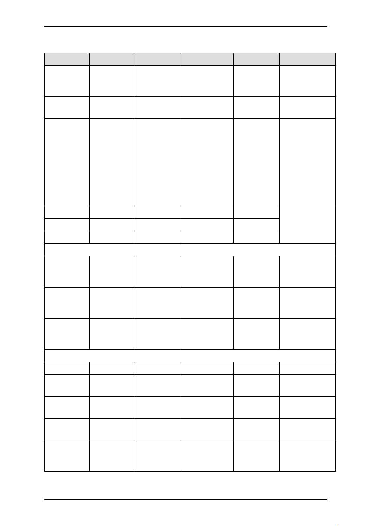
PRIMEQUEST 1000 Series Tool Reference
CHAPTER 1 MMB Web-UI (Web User Interface) Operations
Navigation bar 1st level 2nd level 3rd level Privileges Remarks
Console
Redirection
RW Displays the console
output of the
partition.
Mode RW Sets the mode for the
partition.
PSA RW See CHAPTER 3
PSA Web-UI (Web
User Interface)
Operations.
Only the
PRIMEQUEST 1000
series system
displays the [PSA]
menu.
Partition#1 Same as for
Partition#2
Partition#0
Partition#3
User Administration
User List RW Lists, edits, and
deletes registered
user accounts.
Change
Password
RW Changes the
password of the user's
own account.
Who RO Displays a user who
has logged in to the
MMB.
Network Configuration
Date/Time RW
Network
Interface
IPv4 Interface
RW Sets the IPv4 IP
address, etc.
IPv6 Interface
RW Sets the IPv6 IP
address, etc.
Management
LAN Port
Configuration
RW Configures the Port
VLAN of the MMB
HUB.
6 C122-E110-10EN
Page 39

PRIMEQUEST 1000 Series Tool Reference
CHAPTER 1 MMB Web-UI (Web User Interface) Operations
Navigation bar 1st level 2nd level 3rd level Privileges Remarks
Network
RW
Protocols
Refresh Rate RW Sets the refresh rate
of the Web-UI
window.
SNMP
Configuration
RW This menu is
displayed only if
SNMP is set to
Enable in Network
Protocols.
Community RW This menu is
displayed only if
SNMP is set to
Enable in Network
Protocols.
Trap RW This menu is
displayed only if
SNMP is set to
Enable in Network
Protocols.
SNMPv3
Configuration
RW This menu is
displayed only if
SNMP is set to
Enable in Network
Protocols.
SSL
Create CSR RW Creates a secret key
and CSR.
Export Key/CSR RW Exports a secret key
and CSR.
Import Security
RW Installs a certificate.
Certificate
Create
Selfsigned
RW Creates a self-signed
certificate.
Certificate
SSH
SSH Server Key RW Creates a private key
for the SSH server.
Remote Server
Management
RW
7 C122-E110-10EN
Page 40
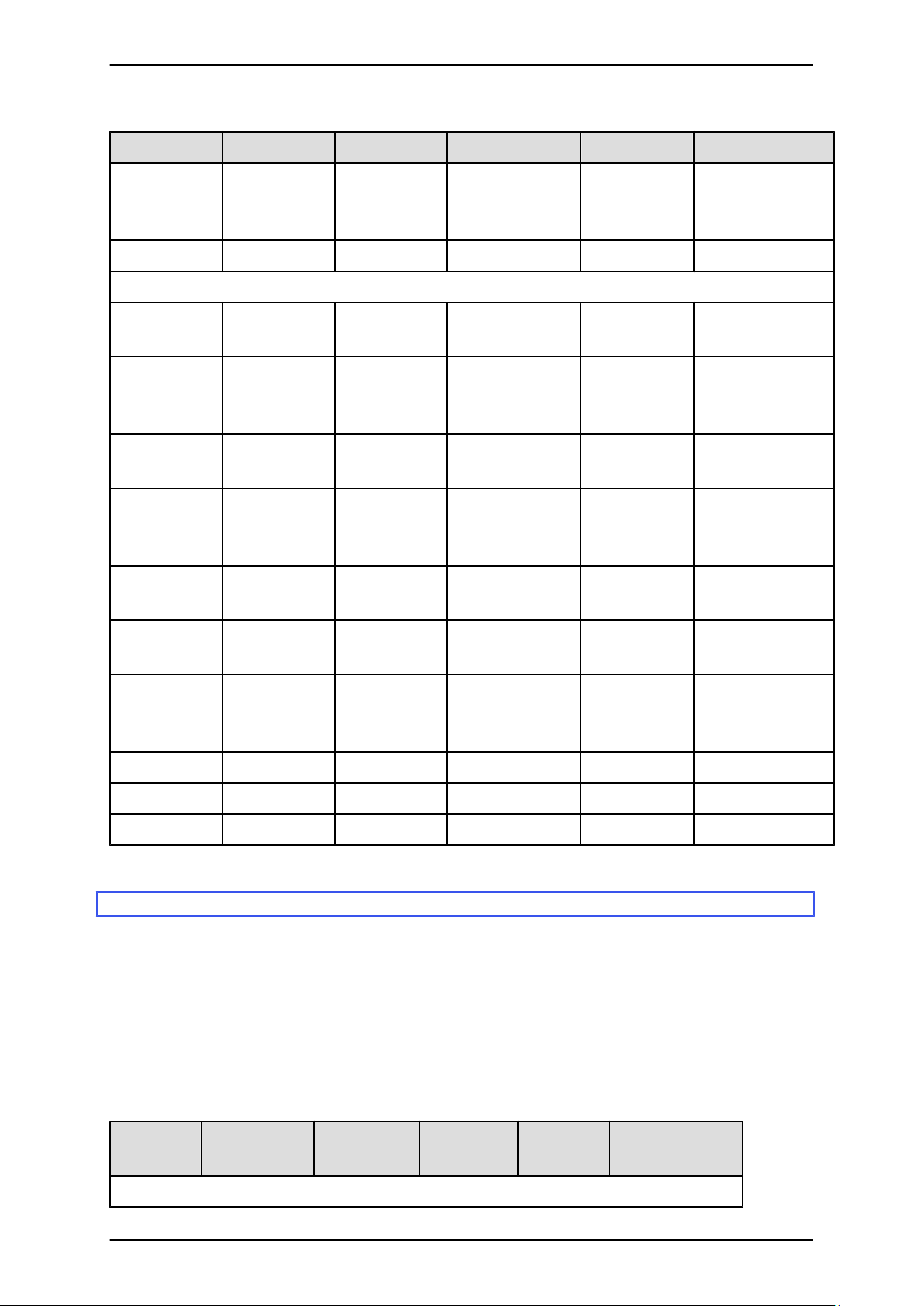
PRIMEQUEST 1000 Series Tool Reference
CHAPTER 1 MMB Web-UI (Web User Interface) Operations
Navigation bar 1st level 2nd level 3rd level Privileges Remarks
Access Control RW Sets the IP filtering
that permits
connections.
Alarm E-Mail RW
Maintenance
Firmware
Update
Unified
Firmware
Update
Backup/Restore
Backs up and restores
Configuration
Backup/Restore
MMB
Configuration
Backup EFI
Configuration
Restore EFI
Configuration
Maintenance
RW Performs
Wizard
REMCS
RW Performs a batch
update.
setting information.
RW
RW
RW
maintenance through
a wizard.
REMCS
Detailed Setup
RW
RW
1.1.2 Web-UI menus (Operator)
This section lists the Web-UI menus that are available with the Operator privileges.
The meanings of abbreviations in the table are as follows:
- RW: The account user can refer to and set information and control operation from the menu.
- RO: The account user can only refer to information from the menu.
- N/A: The account user cannot view the menu and submenus.
TABLE 1.3 Web-UI menus (Operator)
Navigation
bar
System
1st level 2nd level 3rd level Privileges Remarks
8 C122-E110-10EN
Page 41

PRIMEQUEST 1000 Series Tool Reference
CHAPTER 1 MMB Web-UI (Web User Interface) Operations
Navigation
1st level 2nd level 3rd level Privileges Remarks
bar
System Status RO Displays the overall
system status.
System Event
Log
RO Displays system
event logs.
Operation Log RO Displays the
operations on the
Web-UI and CLI.
Partition Event
Log
RO Displays the
REMCS
notification
messages of a
PRIMEQUEST
partition, only in the
PRIMEQUEST
1800E2.
System
Information
RO Displays system
information, such as
the system name or
product name.
Firmware
Information
RO Displays firmware
version information.
System Setup RO Sets the system
configuration.
System Power
RO Controls the power.
Control
LEDs RW Displays the LED
status.
Power Supply RO Displays the power
supply status.
Fans RO Displays the fan
status.
Temperature RO Displays the
temperatures
detected by the
temperature sensors
of the
PRIMEQUEST
1000 series system.
SB
9 C122-E110-10EN
Page 42
PRIMEQUEST 1000 Series Tool Reference
CHAPTER 1 MMB Web-UI (Web User Interface) Operations
Navigation
1st level 2nd level 3rd level Privileges Remarks
bar
SB#0 RW Displays the SB
SB#1 RW
status.
The menu is not
SB#2 RW
SB#3 RW
displayed for an
unmounted SB.
IOB
IOB#0 RW Displays the IOB
IOB#1 RW
status.
The menu is not
displayed for an
unmounted IOB.
GSPB
GSPB#0 RW Displays the GSPB
GSPB#1 RW
status.
The menu is not
displayed for an
unmounted GSPB.
SASU
SASU#0 RW Displays the SAS
SASU#1 RW
disk unit status.
The menu is not
SASU#2 RW
SASU#3 RW
displayed for an
unmounted SAS
disk unit.
PCI_Box
If no PCI_Box is
connected, this
menu is not
displayed.
PCI_Box#0
PCI_Box#1
RW Displays the
RW
PCI_Box status.
The menu is not
displayed for an
unmounted
PCI_Box.
Other Boards
DVDB RW Displays and
controls the DVDB
status.
MMB
10 C122-E110-10EN
Page 43

PRIMEQUEST 1000 Series Tool Reference
CHAPTER 1 MMB Web-UI (Web User Interface) Operations
Navigation
1st level 2nd level 3rd level Privileges Remarks
bar
MMB#0 RW Displays
MMB#1 RW
information on
MMBs and
configures LEDs.
Partition
Power Control RW Controls the
partition power.
Schedule
Schedule
Control
RW Sets scheduled
operations.
Schedule List RW Sets the power-on/
off schedule.
DVD Switch RW Switches the DVD.
Partition
Configuration
RO Changes the
partition
configuration.
Reserved SB
Configuration
Console
RO Defines a Reserved
SB.
RO
Redirection
Setup
IPv4 Console
Redirection
Setup
RO Configures video
redirection, remote
storage, and text
console redirection.
IPv6 Console
Redirection
Setup
RO Configures prefix
length, video
redirection, remote
storage, and text
console redirection.
Partition#0 If no board belongs
to the partition, this
submenu is not
displayed.
Information RO Displays the
partition status and
partition-related
information.
11 C122-E110-10EN
Page 44

PRIMEQUEST 1000 Series Tool Reference
CHAPTER 1 MMB Web-UI (Web User Interface) Operations
Navigation
1st level 2nd level 3rd level Privileges Remarks
bar
ASR Control RO Sets the conditions
for automatically
restarting the
partition.
Console
Redirection
RW Displays the console
output of the
partition.
Mode RW Sets the mode for the
partition.
PSA RW See CHAPTER 3
PSA Web-UI (Web
User Interface)
Operations.
Only the
PRIMEQUEST
1000 series system
displays the [PSA]
menu.
Partition#1 Same as for
Partition#2
Partition#0
Partition#3
User Administration
User List N/A Lists, edits, and
deletes registered
user accounts.
Change
Password
RW Changes the
password of the
user's own account.
Who RO Displays a user who
has logged in to the
MMB.
Network Configuration
Date/Time RO
Network
RO
Interface
IPv4 Interface
IPv6 Interface
RO Sets the IPv4 IP
address, etc.
RO Sets the IPv6 IP
address, etc.
12 C122-E110-10EN
Page 45

PRIMEQUEST 1000 Series Tool Reference
CHAPTER 1 MMB Web-UI (Web User Interface) Operations
Navigation
1st level 2nd level 3rd level Privileges Remarks
bar
Management
LAN Port
Configuration
Network
N/A Configures the Port
VLAN of the MMB
HUB.
RO
Protocols
Refresh Rate RW Sets the refresh rate
of the Web-UI
window.
SNMP
Configuration
N/A This menu is
displayed only if
SNMP is set to
Enable in Network
Protocols.
Community N/A This menu is
displayed only if
SNMP is set to
Enable in Network
Protocols.
Trap N/A This menu is
displayed only if
SNMP is set to
Enable in Network
Protocols.
SNMPv3
Configuration
N/A This menu is
displayed only if
SNMP is set to
Enable in Network
Protocols.
SSL
Create CSR N/A Creates a secret key
and CSR.
Export Key/
CSR
Import Security
N/A Exports a secret key
and CSR.
N/A Installs a certificate.
Certificate
Create
Selfsigned
N/A Creates a self-
signed certificate.
Certificate
SSH
13 C122-E110-10EN
Page 46
PRIMEQUEST 1000 Series Tool Reference
CHAPTER 1 MMB Web-UI (Web User Interface) Operations
Navigation
1st level 2nd level 3rd level Privileges Remarks
bar
SSH Server
Key
Remote Server
N/A
N/A Creates a private key
for the SSH server.
Management
Access Control N/A Sets the IP filtering
that permits
connections.
Alarm E-Mail N/A
Maintenance
Firmware
Update
Unified
Firmware
N/A Performs a batch
update.
Update
Backup/Restore
Configuration
Backs up and
restores setting
information.
Backup/
N/A
Restore MMB
Configuration
Backup EFI
N/A
Configuration
Restore EFI
N/A
Configuration
Maintenance
Wizard
N/A Performs
maintenance
through a wizard.
REMCS
REMCS
Detailed Setup
N/A
N/A
1.1.3 Web-UI menus (Partition Operator)
This section lists the Web-UI menus that are available with the Partition Operator privileges.
The meanings of abbreviations in the table are as follows:
- RW: The account user can refer to and set information and control operation from the menu.
- RO: The account user can only refer to information from the menu.
- N/A: The account user cannot view the menu and submenus.
14 C122-E110-10EN
Page 47

PRIMEQUEST 1000 Series Tool Reference
CHAPTER 1 MMB Web-UI (Web User Interface) Operations
TABLE 1.4 Web-UI menus (Partition Operator)
Navigation
bar
1st level 2nd level 3rd level Privileges
(Same
partition)
Privileges
(Other
partition)
Remarks
System
System Status RO RO Displays the
overall system
status.
System Event
Log
RO RO Displays system
event logs.
Operation Log RO RO Displays the
operations on the
Web-UI and
CLI.
Partition Event
Log
RO RO Displays the
REMCS
notification
messages of a
PRIMEQUEST
partition, only in
the
PRIMEQUEST
1800E2.
System
Information
RO RO Displays system
information,
such as the
system name or
product name.
Firmware
Information
RO RO Displays
firmware
version
information.
System Setup RO RO Sets the system
configuration.
System Power
Control
RO RO Controls the
power.
LEDs RW RW Displays the
LED status.
15 C122-E110-10EN
Page 48
PRIMEQUEST 1000 Series Tool Reference
CHAPTER 1 MMB Web-UI (Web User Interface) Operations
Navigation
bar
1st level 2nd level 3rd level Privileges
(Same
partition)
Privileges
(Other
partition)
Remarks
Power Supply RO RO Displays the
power supply
status.
Fans RO RO Displays the fan
status.
Temperature RO RO Displays the
temperatures
detected by the
temperature
sensors of the
PRIMEQUEST
1000 series
system.
SB
SB#0 RO RO Displays the SB
SB#1 RO RO
status.
The menu is not
SB#2 RO RO
SB#3 RO RO
displayed for an
unmounted SB.
IOB
IOB#0 RO RO Displays the IOB
IOB#1 RO RO
status.
The menu is not
displayed for an
unmounted IOB.
GSPB
GSPB#0 RO RO Displays the
GSPB#1 RO RO
GSPB status.
The menu is not
displayed for an
unmounted
GSPB.
SASU
SASU#0 RO RO Displays the
SASU#1 RO RO
SAS disk unit
status.
SASU#2 RO RO
SASU#3 RO RO
The menu is not
displayed for an
16 C122-E110-10EN
Page 49
PRIMEQUEST 1000 Series Tool Reference
CHAPTER 1 MMB Web-UI (Web User Interface) Operations
Navigation
bar
1st level 2nd level 3rd level Privileges
(Same
partition)
Privileges
(Other
partition)
Remarks
unmounted SAS
disk unit.
PCI_Box
If no PCI_Box is
connected, this
menu is not
displayed.
PCI_Box#0
PCI_Box#1
RO RO Displays the
RO RO
PCI_Box status.
The menu is not
displayed for an
unmounted
PCI_Box.
Other Boards
DVDB RO RO Displays and
controls the
DVDB status.
MMB
MMB#0 RO RO Displays
MMB#1 RO RO
information on
MMBs and
configures
LEDs.
Partition
Power Control RW RO Controls the
partition power.
Schedule
Schedule
Control
Schedule
List
RW RO Sets scheduled
operations.
RW RO Sets the power-
on/off schedule.
DVD Switch RW RO Switches the
DVD.
Partition
Configuration
RO RO Changes the
partition
configuration.
17 C122-E110-10EN
Page 50

PRIMEQUEST 1000 Series Tool Reference
CHAPTER 1 MMB Web-UI (Web User Interface) Operations
Navigation
1st level 2nd level 3rd level Privileges
bar
Reserved SB
Configuration
Console
Redirection
Setup
(Same
partition)
Privileges
(Other
partition)
Remarks
RO RO Defines a
Reserved SB.
RO RO
IPv4
RO RO Configures
Console
Redirection
Setup
video
redirection,
remote storage,
and text console
redirection.
IPv6
Console
Redirection
Setup
RO RO Configures
prefix length,
video
redirection,
remote storage,
and text console
redirection.
Partition#0 If no board
belongs to the
partition, this
submenu is not
displayed.
Information RO N/A Displays the
partition status
and partitionrelated
information.
ASR
Control
RW N/A Sets the
conditions for
automatically
restarting the
partition.
Console
Redirection
RW N/A Displays the
console output of
the partition.
Mode RW N/A Sets the mode for
the partition.
PSA RW N/A See CHAPTER
3 PSA Web-UI
18 C122-E110-10EN
Page 51
PRIMEQUEST 1000 Series Tool Reference
CHAPTER 1 MMB Web-UI (Web User Interface) Operations
Navigation
bar
1st level 2nd level 3rd level Privileges
(Same
partition)
Privileges
(Other
partition)
Remarks
(Web User
Interface)
Operations.
Only the
PRIMEQUEST
1000 series
system displays
the [PSA] menu.
Partition#1 Same as for
Partition#2
Partition#0
Partition#3
User Administration
User List N/A N/A Lists, edits, and
deletes
registered user
accounts.
Change
Password
RW N/A Changes the
password of the
user's own
account.
Who RO RO Displays a user
who has logged
in to the MMB.
Network Configuration
Date/Time RO RO
Network
Interface
Management
LAN Port
Configuration
IPv4
Interface
IPv6
Interface
N/A N/A Configures the
RO RO Sets the IPv4 IP
address, etc.
RO RO Sets the IPv6 IP
address, etc.
Port VLAN of
the MMB HUB.
Network
Protocols
RO RO
19 C122-E110-10EN
Page 52

PRIMEQUEST 1000 Series Tool Reference
CHAPTER 1 MMB Web-UI (Web User Interface) Operations
Navigation
bar
1st level 2nd level 3rd level Privileges
(Same
partition)
Privileges
(Other
partition)
Remarks
Refresh Rate RW RW Sets the refresh
rate of the Web-
UI window.
SNMP
Configuration
N/A N/A This menu is
displayed only if
SNMP is set to
Enable in
Network
Protocols.
Community N/A N/A This menu is
displayed only if
SNMP is set to
Enable in
Network
Protocols.
Trap N/A N/A This menu is
displayed only if
SNMP is set to
Enable in
Network
Protocols.
SNMPv3
Configurati
on
N/A N/A This menu is
displayed only if
SNMP is set to
Enable in
Network
Protocols.
SSL
Create CSR N/A N/A Creates a secret
key and CSR.
Export Key/
CSR
Import
Security
N/A N/A Exports a secret
key and CSR.
N/A N/A Installs a
certificate.
Certificate
Create
N/A N/A Creates a selfSelfsigned
Certificate
SSH
20 C122-E110-10EN
signed
certificate.
Page 53

PRIMEQUEST 1000 Series Tool Reference
CHAPTER 1 MMB Web-UI (Web User Interface) Operations
Navigation
bar
SSH Server
1st level 2nd level 3rd level Privileges
(Same
partition)
N/A N/A Creates a private
Key
Privileges
(Other
partition)
Remarks
key for the SSH
server.
Remote Server
N/A N/A
Management
Access Control N/A N/A Sets the IP
filtering that
permits
connections.
Alarm E-Mail N/A N/A
Maintenance
Firmware
Update
Unified
Firmware
N/A N/A Performs a batch
update.
Update
Backup/
Backs up and
Restore
Configuration
Backup/
Restore
MMB
Configurati
on
Backup EFI
Configurati
on
Restore EFI
Configurati
on
Maintenance
N/A N/A Performs
Wizard
restores setting
information.
N/A N/A
N/A N/A
N/A N/A
maintenance
through a
wizard.
REMCS
REMCS
Detailed
N/A N/A
N/A N/A
Setup
21 C122-E110-10EN
Page 54
PRIMEQUEST 1000 Series Tool Reference
CHAPTER 1 MMB Web-UI (Web User Interface) Operations
1.1.4 Web-UI menus (User)
This section lists the Web-UI menus that are available with the User privileges.
The meanings of abbreviations in the table are as follows:
- RW: The account user can refer to and set information and control operation from the menu.
- RO: The account user can only refer to information from the menu.
- N/A: The account user cannot view the menu and submenus.
TABLE 1.5 Web-UI menus (User)
Navigation bar 1st level 2nd level 3rd level Privileges Remarks
System
System Status RO Displays the
overall system
status.
System Event
Log
Operation Log
Partition Event
Log
System
Information
Firmware
Information
RO Displays system
event logs.
RO Displays the
operations on the
Web-UI and CLI.
RO Displays the
REMCS
notification
messages of a
PRIMEQUEST
partition, only in
the PRIMEQUEST
1800E2.
RO Displays system
information, such
as the system name
or product name.
RO Displays firmware
version
information.
System Setup RO Sets the system
configuration.
System Power
Control
RO Controls the
power.
LEDs RW Displays the LED
status.
22 C122-E110-10EN
Page 55

PRIMEQUEST 1000 Series Tool Reference
CHAPTER 1 MMB Web-UI (Web User Interface) Operations
Navigation bar 1st level 2nd level 3rd level Privileges Remarks
Power Supply RO Displays the power
supply status.
Fans RO Displays the fan
status.
Temperature RO Displays the
temperatures
detected by the
temperature
sensors of the
PRIMEQUEST
1000 series system.
SB
SB#0 RO Displays the SB
SB#1 RO
status.
The menu is not
SB#2 RO
SB#3 RO
IOB
displayed for an
unmounted SB.
IOB#0 RO Displays the IOB
IOB#1 RO
status.
The menu is not
displayed for an
unmounted IOB.
GSPB
GSPB#0 RO Displays the GSPB
GSPB#1 RO
status.
The menu is not
displayed for an
unmounted GSPB.
SASU
SASU#0 RO Displays the SAS
SASU#1 RO
disk unit status.
The menu is not
SASU#2 RO
SASU#3 RO
displayed for an
unmounted SAS
disk unit.
PCI_Box
If no PCI_Box is
connected, this
menu is not
displayed.
23 C122-E110-10EN
Page 56

PRIMEQUEST 1000 Series Tool Reference
CHAPTER 1 MMB Web-UI (Web User Interface) Operations
Navigation bar 1st level 2nd level 3rd level Privileges Remarks
PCI_Box#0
PCI_Box#1
RO Displays the
RO
PCI_Box status.
The menu is not
displayed for an
unmounted
PCI_Box.
Other Boards
DVDB RO Displays and
controls the DVDB
status.
MMB
MMB#0 RO Displays
MMB#1 RO
information on
MMBs and
configures LEDs.
Partition
Power Control RO Controls the
partition power.
Schedule
Schedule
Control
RO Sets scheduled
operations.
Schedule List RO Sets the power-on/
off schedule.
DVD Switch RO Switches the DVD.
Partition
Configuration
RO Changes the
partition
configuration.
Reserved SB
Configuration
Console
RO Defines a Reserved
SB.
RO
Redirection
Setup
IPv4 Console
Redirection
Setup
RO Configures video
redirection, remote
storage, and text
console
redirection.
24 C122-E110-10EN
Page 57

PRIMEQUEST 1000 Series Tool Reference
CHAPTER 1 MMB Web-UI (Web User Interface) Operations
Navigation bar 1st level 2nd level 3rd level Privileges Remarks
IPv6 Console
Redirection
Setup
RO Configures prefix
length, video
redirection, remote
storage, and text
console
redirection.
Partition#0 If no board belongs
to the partition, this
submenu is not
displayed.
Information RO Displays the
partition status and
partition-related
information.
ASR Control RO Sets the conditions
for automatically
restarting the
partition.
Console
Redirection
N/A Displays the
console output of
the partition.
Mode RO Sets the mode for
the partition.
PSA RO See CHAPTER 3
PSA Web-UI (Web
User Interface)
Operations.
Only the
PRIMEQUEST
1000 series system
displays the [PSA]
menu.
Partition#1 Same as for
Partition#2
Partition#0
Partition#3
User Administration
User List N/A Lists, edits, and
deletes registered
user accounts.
25 C122-E110-10EN
Page 58

PRIMEQUEST 1000 Series Tool Reference
CHAPTER 1 MMB Web-UI (Web User Interface) Operations
Navigation bar 1st level 2nd level 3rd level Privileges Remarks
Change
Password
RW Changes the
password of the
user's own account.
Who RO Displays a user
who has logged in
to the MMB.
Network Configuration
Date/Time RO
Network
Interface
IPv4 Interface
RO Sets the IPv4 IP
address, etc.
IPv6 Interface
RO Sets the IPv6 IP
address, etc.
Management
LAN Port
Configuration
N/A Configures the Port
VLAN of the
MMB HUB.
Network
RO
Protocols
Refresh Rate RW Sets the refresh rate
of the Web-UI
window.
SNMP
Configuration
N/A This menu is
displayed only if
SNMP is set to
Enable in Network
Protocols.
Community N/A This menu is
displayed only if
SNMP is set to
Enable in Network
Protocols.
Trap N/A This menu is
displayed only if
SNMP is set to
Enable in Network
Protocols.
SNMPv3
Configuration
N/A This menu is
displayed only if
SNMP is set to
26 C122-E110-10EN
Page 59

PRIMEQUEST 1000 Series Tool Reference
CHAPTER 1 MMB Web-UI (Web User Interface) Operations
Navigation bar 1st level 2nd level 3rd level Privileges Remarks
Enable in Network
Protocols.
SSL
Create CSR N/A Creates a secret
key and CSR.
Export Key/CSR N/A Exports a secret
key and CSR.
Import Security
Certificate
Create
Selfsigned
N/A Installs a
certificate.
N/A Creates a self-
signed certificate.
Certificate
SSH
SSH Server Key N/A Creates a private
key for the SSH
server.
Remote Server
N/A
Management
Access Control N/A Sets the IP filtering
that permits
connections.
Alarm E-Mail N/A
Maintenance
Firmware
Update
Unified
Firmware
Update
Backup/Restore
Backs up and
Configuration
Backup/Restore
MMB
Configuration
Backup EFI
Configuration
Restore EFI
Configuration
N/A Performs a batch
update.
restores setting
information.
N/A
N/A
N/A
27 C122-E110-10EN
Page 60
PRIMEQUEST 1000 Series Tool Reference
CHAPTER 1 MMB Web-UI (Web User Interface) Operations
Navigation bar 1st level 2nd level 3rd level Privileges Remarks
Maintenance
Wizard
N/A Performs
maintenance
through a wizard.
REMCS
REMCS
Detailed Setup
N/A
N/A
1.1.5 Web-UI menus (CE)
This section lists the Web-UI menus that are available with the CE privileges.
The meanings of abbreviations in the table are as follows:
- RW: The account user can refer to and set information and control operation from the menu.
- RO: The account user can only refer to information from the menu.
- N/A: The account user cannot view the menu and submenus.
TABLE 1.6 Web-UI menus (CE)
Navigation bar 1st level 2nd level 3rd level Privileges Remarks
System
System Status RO Displays the overall
system status.
System Event
Log
RO Displays system
event logs.
Operation Log RO Displays the
operations on the
Web-UI and CLI.
Partition Event
Log
RO Displays the REMCS
notification messages
of a PRIMEQUEST
partition, only in the
PRIMEQUEST
1800E2.
System
Information
RO Displays system
information, such as
the system name or
product name.
Firmware
Information
RO Displays firmware
version information.
28 C122-E110-10EN
Page 61

PRIMEQUEST 1000 Series Tool Reference
CHAPTER 1 MMB Web-UI (Web User Interface) Operations
Navigation bar 1st level 2nd level 3rd level Privileges Remarks
System Setup RW Sets the system
configuration.
System Power
RO Controls the power.
Control
LEDs RW Displays the LED
status.
Power Supply RW Displays the power
supply status.
Fans RW Displays the fan
status.
Temperature RW Displays the
temperatures
detected by the
temperature sensors
of the
PRIMEQUEST 1000
series system.
SB
SB#0 RW Displays the SB
SB#1 RW
status.
The menu is not
SB#2 RW
SB#3 RW
displayed for an
unmounted SB.
IOB
IOB#0 RW Displays the IOB
IOB#1 RW
status.
The menu is not
displayed for an
unmounted IOB.
GSPB
GSPB#0 RW Displays the GSPB
GSPB#1 RW
status.
The menu is not
displayed for an
unmounted GSPB.
SASU
SASU#0 RW Displays the SAS
SASU#1 RW
disk unit status.
The menu is not
SASU#2 RW
displayed for an
29 C122-E110-10EN
Page 62

PRIMEQUEST 1000 Series Tool Reference
CHAPTER 1 MMB Web-UI (Web User Interface) Operations
Navigation bar 1st level 2nd level 3rd level Privileges Remarks
SASU#3 RW
unmounted SAS disk
unit.
PCI_Box
If no PCI_Box is
connected, this menu
is not displayed.
PCI_Box#0
PCI_Box#1
RW Displays the
RW
PCI_Box status.
The menu is not
displayed for an
unmounted
PCI_Box.
Other Boards
DVDB RW Displays and controls
the DVDB status.
MMB
MMB#0 RW Displays information
MMB#1 RW
on MMBs and
configures LEDs.
Partition
Power Control RO Controls the partition
power.
Schedule
Schedule
Control
RO Sets scheduled
operations.
Schedule List RO Sets the power-on/off
schedule.
DVD Switch RW Switches the DVD.
Partition
Configuration
Reserved SB
Configuration
Console
RO Changes the partition
configuration.
RO Defines a Reserved
SB.
RO
Redirection
Setup
IPv4 Console
Redirection
Setup
RO Configures video
redirection, remote
storage, and text
console redirection.
30 C122-E110-10EN
Page 63

PRIMEQUEST 1000 Series Tool Reference
CHAPTER 1 MMB Web-UI (Web User Interface) Operations
Navigation bar 1st level 2nd level 3rd level Privileges Remarks
IPv6 Console
Redirection
Setup
RO Configures prefix
length, video
redirection, remote
storage, and text
console redirection.
Partition#0 If no board belongs to
the partition, this
submenu is not
displayed.
Information RO Displays the partition
status and partitionrelated information.
ASR Control RO Sets the conditions
for automatically
restarting the
partition.
Console
Redirection
RO Displays the console
output of the
partition.
Mode RO Sets the mode for the
partition.
PSA RO See CHAPTER 3
PSA Web-UI (Web
User Interface)
Operations.
Only the
PRIMEQUEST 1000
series system
displays the [PSA]
menu.
Partition#1 Same as for
Partition#2
Partition#0
Partition#3
User Administration
User List N/A Lists, edits, and
deletes registered
user accounts.
Change
Password
RW Changes the
password of the user's
own account.
31 C122-E110-10EN
Page 64

PRIMEQUEST 1000 Series Tool Reference
CHAPTER 1 MMB Web-UI (Web User Interface) Operations
Navigation bar 1st level 2nd level 3rd level Privileges Remarks
Who RO Displays a user who
has logged in to the
MMB.
Network Configuration
Date/Time RO
Network
Interface
IPv4 Interface
RO Sets the IPv4 IP
address, etc.
IPv6 Interface
RO Sets the IPv6 IP
address, etc.
Management
LAN Port
Configuration
Network
N/A Configures the Port
VLAN of the MMB
HUB.
RO
Protocols
Refresh Rate RW Sets the refresh rate
of the Web-UI
window.
SNMP
Configuration
N/A This menu is
displayed only if
SNMP is set to
Enable in Network
Protocols.
Community N/A This menu is
displayed only if
SNMP is set to
Enable in Network
Protocols.
Trap N/A This menu is
displayed only if
SNMP is set to
Enable in Network
Protocols.
SNMPv3
Configuration
N/A This menu is
displayed only if
SNMP is set to
Enable in Network
Protocols.
SSL
32 C122-E110-10EN
Page 65

PRIMEQUEST 1000 Series Tool Reference
CHAPTER 1 MMB Web-UI (Web User Interface) Operations
Navigation bar 1st level 2nd level 3rd level Privileges Remarks
Create CSR N/A Creates a secret key
and CSR.
Export Key/CSR N/A Exports a secret key
and CSR.
Import Security
N/A Installs a certificate.
Certificate
Create
Selfsigned
N/A Creates a self-signed
certificate.
Certificate
SSH
SSH Server Key N/A Creates a private key
for the SSH server.
Remote Server
N/A
Management
Access Control N/A Sets the IP filtering
that permits
connections.
Alarm E-Mail N/A
Maintenance
Firmware
Update
Unified
Firmware
Update
Backup/Restore
Backs up and restores
Configuration
Backup/Restore
MMB
Configuration
Backup EFI
Configuration
Restore EFI
Configuration
Maintenance
RW Performs
Wizard
REMCS
REMCS
RW Performs a batch
update.
setting information.
RW
RW
RW
maintenance through
a wizard.
RW
33 C122-E110-10EN
Page 66
PRIMEQUEST 1000 Series Tool Reference
CHAPTER 1 MMB Web-UI (Web User Interface) Operations
Navigation bar 1st level 2nd level 3rd level Privileges Remarks
Detailed Setup
RW
1.1.6 Web-UI menus in maintenance mode
Some windows have operating restrictions when maintenance mode is set. These restrictions apply to the user who
sets maintenance mode (referred to below as maintenance personnel) and other users (referred to below as nonmaintenance personnel).
The following table lists the Web-UI window restrictions that apply to maintenance personnel and non-maintenance
personnel in maintenance mode.
The five types of maintenance mode are as follows.
TABLE 1.7 Types of maintenance mode
Maintenance mode Description
Hot System Maintenance
(Target unit not included in a partition)
Active (system) for work
Hot Partition Maintenance
(Target unit in a running partition)
Active (partition) for work
For maintenance work on the target unit not included in
a partition. The work can be performed without stopping
jobs.
For maintenance work on a partition that is still operating
while under maintenance. This work can be performed
without stopping jobs.
Warm System Maintenance
(Target unit in a powered off partition)
Partition stopped for work
For maintenance work on the partition under maintenance
or the partition containing the target maintenance unit.
The partition must be stopped during maintenance.
The partitions not under maintenance need not be stopped.
Cold System Maintenance
(All partitions powered off, breaker on)
For maintenance work that requires the system to be
stopped. All jobs are stopped.
Stopped (standby) for work
Cold System Maintenance
(All partitions powered off, breaker off)
Stopped (AC off) for work
For maintenance work that requires the system to be
stopped and the AC power to be turned off (MMB power
off). All jobs are stopped.
The following sections outline the Web-UI menus that are available in maintenance mode for each type of user
privilege.
- 1.1.7 Web-UI menus in maintenance mode (Administrator)
- 1.1.8 Web-UI menus in maintenance mode (Operator)
- 1.1.9 Web-UI menus in maintenance mode (Partition Operator)
- 1.1.10 Web-UI menus in maintenance mode (User)
- 1.1.11 Web-UI menus in maintenance mode (CE)
- 1.1.12 Web-UI menus in maintenance mode (maintenance personnel)
34 C122-E110-10EN
Page 67
PRIMEQUEST 1000 Series Tool Reference
CHAPTER 1 MMB Web-UI (Web User Interface) Operations
1.1.7 Web-UI menus in maintenance mode (Administrator)
This section outlines the Web-UI menus that are available with the Administrator privileges in maintenance mode.
The maintenance mode column has the following items. For details on the maintenance mode, see 1.1.6 Web-UI
menus in maintenance mode.
- Hot System: Hot System Maintenance (Target unit not included in a partition)
- Hot Partition: Hot Partition Maintenance (Target unit in a running partition)
- Warm System: Warm System Maintenance (Target unit in a powered off partition)
- Cold System: Cold System Maintenance (All partitions powered off, breaker on), and Cold System
Maintenance (All partitions powered off, breaker off)
The meanings of abbreviations in the table are as follows:
RW: The account user can refer to and set information in the window.
RO: The account user can only refer to information in the window.
N/A: The account user cannot view the menu and submenu.
*1 The account user can operate partitions not in maintenance mode in this window.
*2 The account user can operate only partitions in maintenance mode in this window.
*3 The SB is neither a Home SB nor Reserved SB. Alternatively, the SB is the Home SB in the Power Off status
in a partition in the Standby status.
*4 The partition is in the Standby status.
TABLE 1.8 Web-UI menus in maintenance mode (Administrator)
Navigation
bar
1st level 2nd level 3rd level Maintenance
mode
Privileges Remarks
System
System Power
Control
Hot System RW
Hot Partition RO
Warm System RO
Cold System RO
MMB
MMB#0 Hot System RO
Hot Partition RO
Warm System RO
Cold System RO
MMB#1 Same as
for
MMB#0
Partition
Power Control Hot System RW
Hot Partition RW (*1)
35 C122-E110-10EN
Page 68

PRIMEQUEST 1000 Series Tool Reference
CHAPTER 1 MMB Web-UI (Web User Interface) Operations
Navigation
bar
1st level 2nd level 3rd level Maintenance
mode
Privileges Remarks
Warm System RW (*1)
Cold System RO
DVD Switch Hot System RW Outputs a message
depending on the
conditions. (See
TABLE 1.65
Whether a
confirmation
message appears in
maintenance
mode.)
Hot Partition RW Outputs a message
depending on the
conditions. (See
TABLE 1.65
Whether a
confirmation
message appears in
maintenance
mode.)
Partition
Configuration
Warm System RW Outputs a message
depending on the
conditions. (See
TABLE 1.65
Whether a
confirmation
message appears in
maintenance
mode.)
Cold System RW Outputs a message
depending on the
conditions. (See
TABLE 1.65
Whether a
confirmation
message appears in
maintenance
mode.)
Hot System RW [Add...] is
suppressed since
the Free unit may
36 C122-E110-10EN
Page 69
PRIMEQUEST 1000 Series Tool Reference
CHAPTER 1 MMB Web-UI (Web User Interface) Operations
Navigation
1st level 2nd level 3rd level Maintenance
bar
Add SB/IOB/
GSPB to
Partition
Remove SB/
IOB/GSPB
from Partition
Partition
Home
Privileges Remarks
mode
Hot Partition RW (*1)
Warm System RW (*1)
Cold System RO
Same as
for
Partition
Configur
ation
Same as
for
Partition
Configur
ation
Same as
for
Partition
Configur
ation
be a replacement
unit.
Reserved SB
Configuration
Console
Redirection
Network Configuration
Network
Interface
Maintenance Wizard
Firmware
Update
Hot System RW
Hot Partition RW (*1)
Warm System RW (*1)
Cold System RO
Hot System RW
Hot Partition RW (*1)
Warm System RW (*1)
Cold System RO
Hot System RO
Hot Partition RO
Warm System RO
Cold System RO
37 C122-E110-10EN
Page 70
PRIMEQUEST 1000 Series Tool Reference
CHAPTER 1 MMB Web-UI (Web User Interface) Operations
Navigation
1st level 2nd level 3rd level Maintenance
bar
Unified
Firmware
Update
Backup/
Restore
Configuration
Backup/
Restore MMB
Configuration
Privileges Remarks
mode
Hot System RO
Hot Partition RO
Warm System RO
Cold System RO
RW [Backup MMB...]
is not affected by
maintenance
mode.
[Restore MMB...]
can be operated
only by
maintenance
personnel.
Maintenance
Hot System RO
Wizard
Hot Partition RO
Warm System RO
Cold System RO
1.1.8 Web-UI menus in maintenance mode (Operator)
This section outlines the Web-UI menus that are available with the Operator privileges in maintenance mode.
The maintenance mode column has the following items. For details on the maintenance mode, see 1.1.6 Web-UI
menus in maintenance mode.
- Hot System: Hot System Maintenance (Target unit not included in a partition)
- Hot Partition: Hot Partition Maintenance (Target unit in a running partition)
- Warm System: Warm System Maintenance (Target unit in a powered off partition)
- Cold System: Cold System Maintenance (All partitions powered off, breaker on), and Cold System
Maintenance (All partitions powered off, breaker off)
The meanings of abbreviations in the table are as follows:
RW: The account user can refer to and set information in the window.
RO: The account user can only refer to information in the window.
N/A: The account user cannot view the menu and submenu.
*1 The account user can operate partitions not in maintenance mode in this window.
*2 The account user can operate only partitions in maintenance mode in this window.
38 C122-E110-10EN
Page 71
PRIMEQUEST 1000 Series Tool Reference
CHAPTER 1 MMB Web-UI (Web User Interface) Operations
*3 The SB is neither a Home SB nor Reserved SB. Alternatively, the SB is the Home SB in the Power Off status
in a partition in the Standby status.
*4 The partition is in the Standby status.
TABLE 1.9 Web-UI menus in maintenance mode (Operator)
Navigation
bar
1st level 2nd level 3rd level Maintenance
mode
Privileges Remarks
System
System Power
Control
Hot System RO
Hot Partition RO
Warm System RO
Cold System RO
MMB
MMB#0 Hot System RO
Hot Partition RO
Warm System RO
Cold System RO
MMB#1 Same as
for
MMB#0
Partition
Power Control Hot System RW
Hot Partition RW (*1)
Warm System RW (*1)
Cold System RO
DVD Switch Hot System RW Outputs a message
depending on the
conditions. (See
TABLE 1.65
Whether a
confirmation
message appears in
maintenance
mode.)
Hot Partition RW Outputs a message
depending on the
conditions. (See
TABLE 1.65
Whether a
39 C122-E110-10EN
Page 72

PRIMEQUEST 1000 Series Tool Reference
CHAPTER 1 MMB Web-UI (Web User Interface) Operations
Navigation
bar
1st level 2nd level 3rd level Maintenance
mode
Warm System RW Outputs a message
Cold System RW Outputs a message
Privileges Remarks
confirmation
message appears in
maintenance
mode.)
depending on the
conditions. (See
TABLE 1.65
Whether a
confirmation
message appears in
maintenance
mode.)
depending on the
conditions. (See
TABLE 1.65
Whether a
confirmation
message appears in
maintenance
mode.)
Partition
Hot System RO [Add...] is
Configuration
Add SB/IOB/
GSPB to
Partition
Remove SB/
IOB/GSPB
from Partition
Hot Partition RO
Warm System RO
Cold System RO
Same as
for
Partition
Configur
ation
Same as
for
Partition
Configur
ation
suppressed since
the Free unit may
be a replacement
unit.
40 C122-E110-10EN
Page 73
PRIMEQUEST 1000 Series Tool Reference
CHAPTER 1 MMB Web-UI (Web User Interface) Operations
Navigation
1st level 2nd level 3rd level Maintenance
bar
Partition
Home
Reserved SB
Hot System RO
Configuration
Console
Redirection
Network Configuration
Privileges Remarks
mode
Same as
for
Partition
Configur
ation
Hot Partition RO
Warm System RO
Cold System RO
Hot System RW
Hot Partition RW (*1)
Warm System RW (*1)
Cold System RO
Network
Hot System RO
Interface
Maintenance Wizard
Firmware
Update
Unified
Firmware
Update
Backup/
Restore
Configuration
Backup/
Restore MMB
Configuration
Hot Partition RO
Warm System RO
Cold System RO
Hot System N/A
Hot Partition N/A
Warm System N/A
Cold System N/A
N/A [Backup MMB...]
is not affected by
maintenance
mode.
[Restore MMB...]
can be operated
only by
41 C122-E110-10EN
Page 74
PRIMEQUEST 1000 Series Tool Reference
CHAPTER 1 MMB Web-UI (Web User Interface) Operations
Navigation
bar
1st level 2nd level 3rd level Maintenance
mode
Privileges Remarks
maintenance
personnel.
Maintenance
Hot System N/A
Wizard
Hot Partition N/A
Warm System N/A
Cold System N/A
1.1.9 Web-UI menus in maintenance mode (Partition Operator)
This section outlines the Web-UI menus that are available with the Partition Operator privileges in maintenance
mode.
The maintenance mode column has the following items. For details on the maintenance mode, see 1.1.6 Web-UI
menus in maintenance mode.
- Hot System: Hot System Maintenance (Target unit not included in a partition)
- Hot Partition: Hot Partition Maintenance (Target unit in a running partition)
- Warm System: Warm System Maintenance (Target unit in a powered off partition)
- Cold System: Cold System Maintenance (All partitions powered off, breaker on), and Cold System
Maintenance (All partitions powered off, breaker off)
The meanings of abbreviations in the table are as follows:
RW: The account user can refer to and set information in the window.
RO: The account user can only refer to information in the window.
N/A: The account user cannot view the menu and submenu.
*1 The account user can operate partitions not in maintenance mode in this window.
*2 The account user can operate only partitions in maintenance mode in this window.
*3 The SB is neither a Home SB nor Reserved SB. Alternatively, the SB is the Home SB in the Power Off status
in a partition in the Standby status.
*4 The partition is in the Standby status.
TABLE 1.10 Web-UI menus in maintenance mode (Partition Operator)
Navigation
bar
1st level 2nd level3rd level Maintenance
mode
Privileges
(Same
partition)
System
System
Power
Hot System RO RO
Hot Partition RO RO
Control
Warm System RO RO
42 C122-E110-10EN
Privileges
(Other
partition)
Remarks
Page 75
PRIMEQUEST 1000 Series Tool Reference
CHAPTER 1 MMB Web-UI (Web User Interface) Operations
Navigation
bar
1st level 2nd level3rd level Maintenance
mode
Privileges
(Same
partition)
Privileges
(Other
partition)
Cold System RO RO
MMB
MMB#0 Hot System RO RO
Hot Partition RO RO
Warm System RO RO
Cold System RO RO
MMB#1 Same as for MMB#0
Partition
Power
Control
Hot System RW RO
Hot Partition RW (*1) RO
Warm System RW (*1) RO
Cold System RO RO
Remarks
DVD
Switch
Hot System RW RO Outputs a
message
depending on
the conditions.
(See TABLE
1.65 Whether
a confirmation
message
appears in
maintenance
mode.)
Hot Partition RW RO Outputs a
message
depending on
the conditions.
(See TABLE
1.65 Whether
a confirmation
message
appears in
maintenance
mode.)
Warm System RW RO Outputs a
message
depending on
43 C122-E110-10EN
Page 76

PRIMEQUEST 1000 Series Tool Reference
CHAPTER 1 MMB Web-UI (Web User Interface) Operations
Navigation
bar
1st level 2nd level3rd level Maintenance
mode
Cold System RW RO Outputs a
Privileges
(Same
partition)
Privileges
(Other
partition)
Remarks
the conditions.
(See TABLE
1.65 Whether
a confirmation
message
appears in
maintenance
mode.)
message
depending on
the conditions.
(See TABLE
1.65 Whether
a confirmation
message
appears in
maintenance
mode.)
Partition
Hot System RO RO [Add...] is
Configu
ration
Add SB/
IOB/
GSPB to
Partition
Remove
SB/IOB/
GSPB
from
Partition
Hot Partition RO RO
Warm System RO RO
Cold System RO RO
Same as for Partition
Configuration
Same as for Partition
Configuration
suppressed
since the Free
unit may be a
replacement
unit.
Partition
Home
Same as for Partition
Configuration
44 C122-E110-10EN
Page 77
PRIMEQUEST 1000 Series Tool Reference
CHAPTER 1 MMB Web-UI (Web User Interface) Operations
Navigation
1st level 2nd level3rd level Maintenance
bar
Reserve
d SB
Configu
ration
Console
Redirect
ion
Network Configuration
Network
Interface
mode
Privileges
(Same
partition)
Privileges
(Other
partition)
Hot System RO RO
Hot Partition RO RO
Warm System RO RO
Cold System RO RO
Hot System RW N/A
Hot Partition RW (*1) N/A
Warm System RW (*1) N/A
Cold System RO N/A
Hot System RO RO
Hot Partition RO RO
Warm System RO RO
Remarks
Maintenance Wizard
Firmwar
e Update
Unified
Firmwar
e Update
Backup/
Restore
Configu
ration
Backup/
Restore
MMB
Configu
ration
Cold System RO RO
Hot System N/A N/A
Hot Partition N/A N/A
Warm System N/A N/A
Cold System N/A N/A
N/A N/A [Backup
MMB...]
is not affected
by
maintenance
mode.
[Restore
MMB...]
can be
operated only
by
45 C122-E110-10EN
Page 78
PRIMEQUEST 1000 Series Tool Reference
CHAPTER 1 MMB Web-UI (Web User Interface) Operations
Navigation
bar
1st level 2nd level3rd level Maintenance
mode
Privileges
(Same
partition)
Privileges
(Other
partition)
Remarks
maintenance
personnel.
Mainten
Hot System N/A N/A
ance
Wizard
Hot Partition N/A N/A
Warm System N/A N/A
Cold System N/A N/A
1.1.10 Web-UI menus in maintenance mode (User)
This section outlines the Web-UI menus that are available with the User privileges in maintenance mode.
The maintenance mode column has the following items. For details on the maintenance mode, see 1.1.6 Web-UI
menus in maintenance mode.
- Hot System: Hot System Maintenance (Target unit not included in a partition)
- Hot Partition: Hot Partition Maintenance (Target unit in a running partition)
- Warm System: Warm System Maintenance (Target unit in a powered off partition)
- Cold System: Cold System Maintenance (All partitions powered off, breaker on), and Cold System
Maintenance (All partitions powered off, breaker off)
The meanings of abbreviations in the table are as follows:
RW: The account user can refer to and set information in the window.
RO: The account user can only refer to information in the window.
N/A: The account user cannot view the menu and submenu.
*1 The account user can operate partitions not in maintenance mode in this window.
*2 The account user can operate only partitions in maintenance mode in this window.
*3 The SB is neither a Home SB nor Reserved SB. Alternatively, the SB is the Home SB in the Power Off status
in a partition in the Standby status.
*4 The partition is in the Standby status.
TABLE 1.11 Web-UI menus in maintenance mode (User)
Navigation
1st level 2nd level 3rd level Maintenance
bar
System
System Power
Control
Hot System RO
Hot Partition RO
Warm System RO
46 C122-E110-10EN
Privileges Remarks
mode
Page 79
PRIMEQUEST 1000 Series Tool Reference
CHAPTER 1 MMB Web-UI (Web User Interface) Operations
Navigation
bar
1st level 2nd level 3rd level Maintenance
mode
Privileges Remarks
Cold System RO
MMB
MMB#0 Hot System RO
Hot Partition RO
Warm System RO
Cold System RO
MMB#1 Same as
for
MMB#0
Partition
Power Control Hot System RO
Hot Partition RO
Warm System RO
Cold System RO
DVD Switch Hot System RO Outputs a message
depending on the
conditions. (See
TABLE 1.65
Whether a
confirmation
message appears in
maintenance
mode.)
Hot Partition RO Outputs a message
depending on the
conditions. (See
TABLE 1.65
Whether a
confirmation
message appears in
maintenance
mode.)
Warm System RO Outputs a message
depending on the
conditions. (See
TABLE 1.65
Whether a
confirmation
message appears in
47 C122-E110-10EN
Page 80

PRIMEQUEST 1000 Series Tool Reference
CHAPTER 1 MMB Web-UI (Web User Interface) Operations
Navigation
1st level 2nd level 3rd level Maintenance
bar
Partition
Configuration
Privileges Remarks
mode
maintenance
mode.)
Cold System RO Outputs a message
depending on the
conditions. (See
TABLE 1.65
Whether a
confirmation
message appears in
maintenance
mode.)
Hot System RO [Add...] is
suppressed since
the Free unit may
be a replacement
unit.
Hot Partition RO
Add SB/IOB/
GSPB to
Partition
Remove SB/
IOB/GSPB
from Partition
Partition
Home
Reserved SB
Hot System RO
Configuration
Warm System RO
Cold System RO
Same as
for
Partition
Configur
ation
Same as
for
Partition
Configur
ation
Same as
for
Partition
Configur
ation
Hot Partition RO
Warm System RO
Cold System RO
Console
Hot System N/A
48 C122-E110-10EN
Page 81
PRIMEQUEST 1000 Series Tool Reference
CHAPTER 1 MMB Web-UI (Web User Interface) Operations
Navigation
1st level 2nd level 3rd level Maintenance
bar
Redirection
Network Configuration
Network
Hot System RO
Interface
Maintenance Wizard
Firmware
Update
Unified
Firmware
Update
Privileges Remarks
mode
Hot Partition N/A
Warm System N/A
Cold System N/A
Hot Partition RO
Warm System RO
Cold System RO
Hot System N/A
Hot Partition N/A
Warm System N/A
Cold System N/A
Backup/
Restore
Configuration
Backup/
N/A [Backup MMB...]
Restore MMB
Configuration
Maintenance
Hot System N/A
Wizard
Hot Partition N/A
Warm System N/A
Cold System N/A
is not affected by
maintenance
mode.
[Restore MMB...]
can be operated
only by
maintenance
personnel.
1.1.11 Web-UI menus in maintenance mode (CE)
This section outlines the Web-UI menus that are available with the CE privileges in maintenance mode.
49 C122-E110-10EN
Page 82
PRIMEQUEST 1000 Series Tool Reference
CHAPTER 1 MMB Web-UI (Web User Interface) Operations
The maintenance mode column has the following items. For details on the maintenance mode, see 1.1.6 Web-UI
menus in maintenance mode.
- Hot System: Hot System Maintenance (Target unit not included in a partition)
- Hot Partition: Hot Partition Maintenance (Target unit in a running partition)
- Warm System: Warm System Maintenance (Target unit in a powered off partition)
- Cold System: Cold System Maintenance (All partitions powered off, breaker on), and Cold System
Maintenance (All partitions powered off, breaker off)
The meanings of abbreviations in the table are as follows:
RW: The account user can refer to and set information in the window.
RO: The account user can only refer to information in the window.
N/A: The account user cannot view the menu and submenu.
*1 The account user can operate partitions not in maintenance mode in this window.
*2 The account user can operate only partitions in maintenance mode in this window.
*3 The SB is neither a Home SB nor Reserved SB. Alternatively, the SB is the Home SB in the Power Off status
in a partition in the Standby status.
*4 The partition is in the Standby status.
TABLE 1.12 Web-UI menus in maintenance mode (CE)
Navigation
bar
1st level 2nd level 3rd level Maintenance
mode
Privileges Remarks
System
System Power
Control
Hot System RO
Hot Partition RO
Warm System RO
Cold System RO
MMB
MMB#0 Hot System RO
Hot Partition RO
Warm System RO
Cold System RO
MMB#1 Same as
for
MMB#0
Partition
Power Control Hot System RO
Hot Partition RO
Warm System RO
Cold System RO
50 C122-E110-10EN
Page 83
PRIMEQUEST 1000 Series Tool Reference
CHAPTER 1 MMB Web-UI (Web User Interface) Operations
Navigation
bar
1st level 2nd level 3rd level Maintenance
mode
Privileges Remarks
DVD Switch Hot System RW Outputs a message
depending on the
conditions. (See
TABLE 1.65
Whether a
confirmation
message appears in
maintenance
mode.)
Hot Partition RW Outputs a message
depending on the
conditions. (See
TABLE 1.65
Whether a
confirmation
message appears in
maintenance
mode.)
Partition
Configuration
Warm System RW Outputs a message
depending on the
conditions. (See
TABLE 1.65
Whether a
confirmation
message appears in
maintenance
mode.)
Cold System RW Outputs a message
depending on the
conditions. (See
TABLE 1.65
Whether a
confirmation
message appears in
maintenance
mode.)
Hot System RO [Add...] is
suppressed since
the Free unit may
be a replacement
unit.
Hot Partition RO
51 C122-E110-10EN
Page 84
PRIMEQUEST 1000 Series Tool Reference
CHAPTER 1 MMB Web-UI (Web User Interface) Operations
Navigation
1st level 2nd level 3rd level Maintenance
bar
Add SB/IOB/
GSPB to
Partition
Remove SB/
IOB/GSPB
from Partition
Partition
Home
Privileges Remarks
mode
Warm System RO
Cold System RO
Same as
for
Partition
Configur
ation
Same as
for
Partition
Configur
ation
Same as
for
Partition
Configur
ation
Reserved SB
Configuration
Console
Redirection
Network Configuration
Network
Interface
Maintenance Wizard
Firmware
Update
Hot System RO
Hot Partition RO
Warm System RO
Cold System RO
Hot System RO
Hot Partition RO
Warm System RO
Cold System RO
Hot System RO
Hot Partition RO
Warm System RO
Cold System RO
Unified
Firmware
Update
Hot System RO
Hot Partition RO
Warm System RO
52 C122-E110-10EN
Page 85
PRIMEQUEST 1000 Series Tool Reference
CHAPTER 1 MMB Web-UI (Web User Interface) Operations
Navigation
bar
1st level 2nd level 3rd level Maintenance
mode
Privileges Remarks
Cold System RO
Backup/
Restore
Configuration
Backup/
RW [Backup MMB...]
Restore MMB
Configuration
Maintenance
Hot System RO
Wizard
Hot Partition RO
is not affected by
maintenance
mode.
[Restore MMB...]
can be operated
only by
maintenance
personnel.
Warm System RO
Cold System RO
1.1.12 Web-UI menus in maintenance mode (maintenance personnel)
This section outlines the Web-UI menus that are available to maintenance personnel (Administrator or CE
privileges) in maintenance mode.
The maintenance mode column has the following items. For details on the maintenance mode, see 1.1.6 Web-UI
menus in maintenance mode.
- Hot System: Hot System Maintenance (Target unit not included in a partition)
- Hot Partition: Hot Partition Maintenance (Target unit in a running partition)
- Warm System: Warm System Maintenance (Target unit in a powered off partition)
- Cold System: Cold System Maintenance (All partitions powered off, breaker on), and Cold System
Maintenance (All partitions powered off, breaker off)
The meanings of abbreviations in the table are as follows:
RW: The account user can refer to and set information in the window.
RO: The account user can only refer to information in the window.
N/A: The account user cannot view the menu and submenu.
*1 The account user can operate partitions not in maintenance mode in this window.
*2 The account user can operate only partitions in maintenance mode in this window.
*3 The SB is neither a Home SB nor Reserved SB. Alternatively, the SB is the Home SB in the Power Off status
in a partition in the Standby status.
*4 The partition is in the Standby status.
53 C122-E110-10EN
Page 86
PRIMEQUEST 1000 Series Tool Reference
CHAPTER 1 MMB Web-UI (Web User Interface) Operations
TABLE 1.13 Web-UI menus in maintenance mode (maintenance personnel)
Navigation
bar
1st level 2nd level 3rd level Maintenance
mode
Privileges
(Administrator)
Privileges
(CE)
System
System Power
Control
Hot System RW RO
Hot Partition RO RO
Warm
RO RO
System
Cold System RW RW
MMB
MMB#0 Hot System RW RW
Hot Partition RO RO
Warm
RO RO
System
Cold System RW RW
MMB#1 Same as for MMB#0
Partition
Remarks
Power Control Hot System RW RO
Hot Partition RW (*1) RO
Warm
RW RW (*2)
System
Cold System RW RW
DVD Switch Hot System RW RW Outputs a
message
depending
on the
conditions.
(See
TABLE
1.65
Whether a
confirmati
on
message
appears in
maintenan
ce mode.)
54 C122-E110-10EN
Page 87

PRIMEQUEST 1000 Series Tool Reference
CHAPTER 1 MMB Web-UI (Web User Interface) Operations
Navigation
bar
1st level 2nd level 3rd level Maintenance
mode
Hot Partition RW RW Outputs a
Warm
System
Privileges
(Administrator)
Privileges
(CE)
RW RW Outputs a
Remarks
message
depending
on the
conditions.
(See
TABLE
1.65
Whether a
confirmati
on
message
appears in
maintenan
ce mode.)
message
depending
on the
conditions.
(See
TABLE
1.65
Whether a
confirmati
on
message
appears in
maintenan
ce mode.)
Cold System RW RW Outputs a
message
depending
on the
conditions.
(See
TABLE
1.65
Whether a
confirmati
on
message
appears in
55 C122-E110-10EN
Page 88

PRIMEQUEST 1000 Series Tool Reference
CHAPTER 1 MMB Web-UI (Web User Interface) Operations
Navigation
1st level 2nd level 3rd level Maintenance
bar
Partition
Hot System RW RO [Add...] is
Configuration
Add SB/
IOB/
GSPB to
Partition
mode
Privileges
(Administrator)
Privileges
Hot Partition RW RO
Warm
RW RO
System
Cold System RW RO
Same as for Partition
Configuration
Remarks
(CE)
maintenan
ce mode.)
suppressed
since the
Free unit
may be a
replaceme
nt unit.
Remove
SB/IOB/
GSPB
from
Partition
Partition
Home
Reserved SB
Hot System RW RO
Configuration
Console
Redirection
Same as for Partition
Configuration
Same as for Partition
Configuration
Hot Partition RW RO
Warm
RW RO
System
Cold System RW RO
Hot System RW RO
Hot Partition RO RO
Warm
RO RO
System
Cold System RW RW
Network Configuration
Network
Interface
Hot System RO RO
Hot Partition RO RO
56 C122-E110-10EN
Page 89
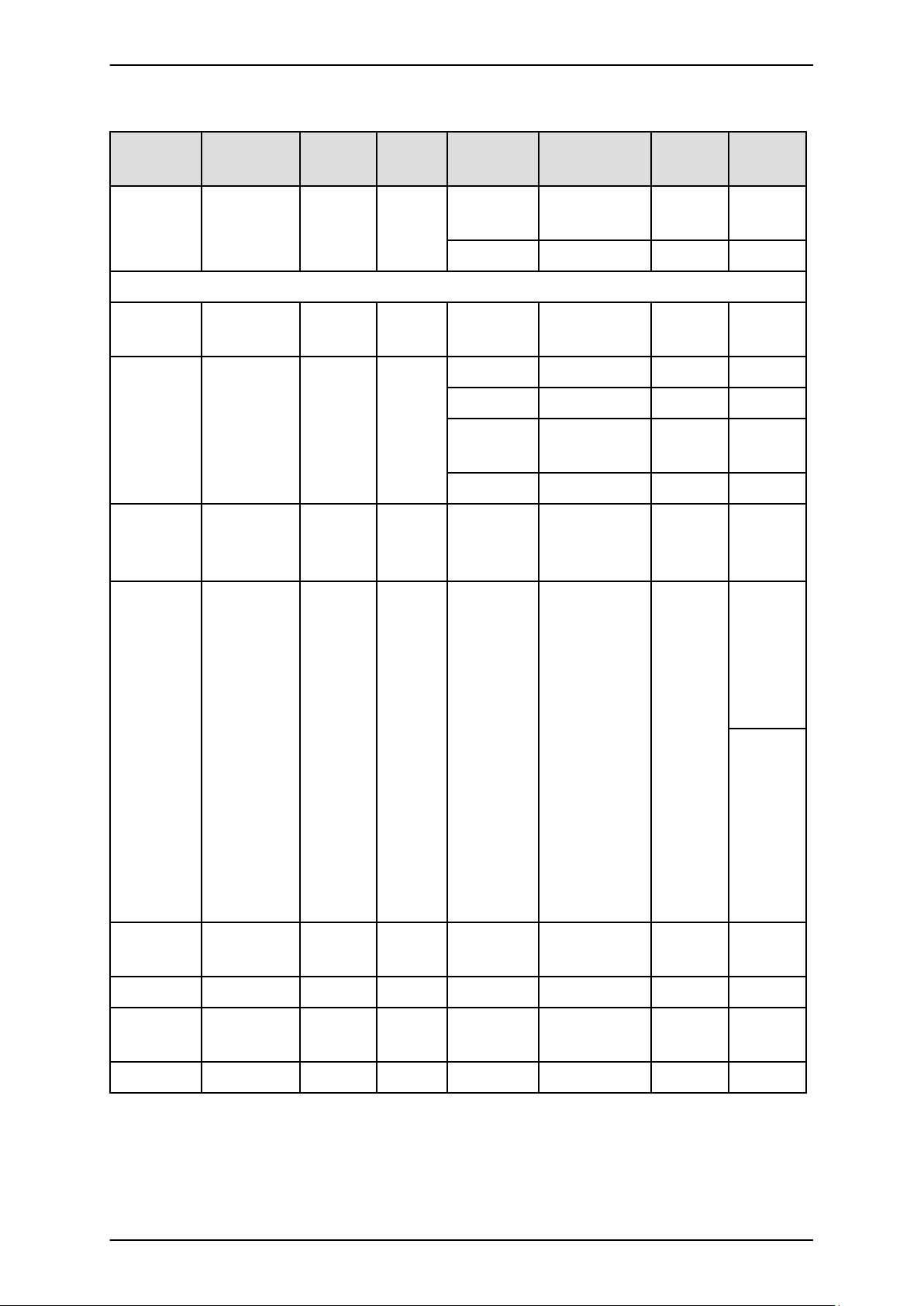
PRIMEQUEST 1000 Series Tool Reference
CHAPTER 1 MMB Web-UI (Web User Interface) Operations
Navigation
1st level 2nd level 3rd level Maintenance
bar
Maintenance Wizard
Firmware
Update
Unified
Firmware
Update
Backup/
Restore
Configuration
mode
Warm
Privileges
(Administrator)
RO RO
Privileges
(CE)
System
Cold System RO RO
Hot System RW RW
Hot Partition RO RO
Warm
RO RO
System
Cold System RW RW
Remarks
Backup/
RW RW [Backup
Restore
MMB
Configurat
ion
Maintenance
Hot System RW RW
Wizard
Hot Partition RW RW
Warm
RW RW
System
MMB...]
is not
affected by
maintenan
ce mode.
[Restore
MMB...]
can be
operated
only by
maintenan
ce
personnel.
Cold System RW RW
57 C122-E110-10EN
Page 90
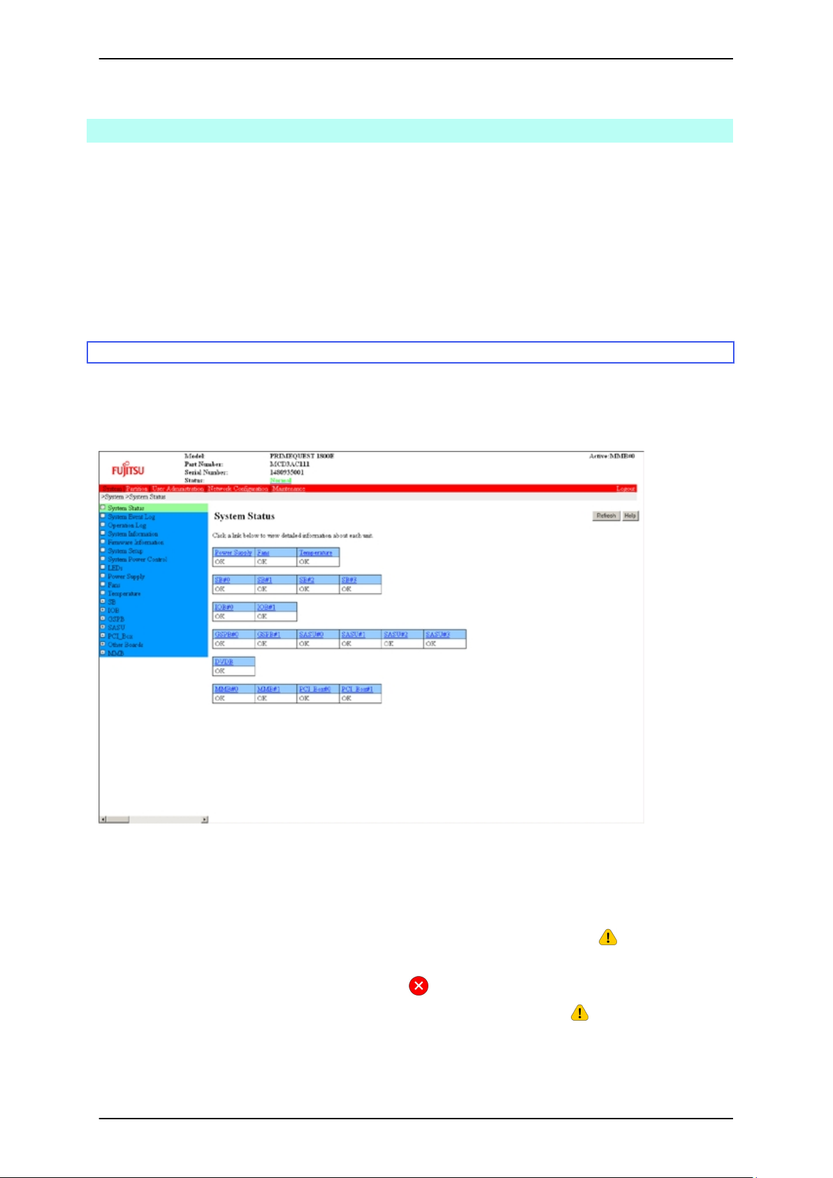
PRIMEQUEST 1000 Series Tool Reference
CHAPTER 1 MMB Web-UI (Web User Interface) Operations
1.2 [System] Menu
You can display the status of and configure the hardware components in the entire PRIMEQUEST 1000 series
system from the [System] menu.
Remarks
If [Part Number] or [Serial Number] (the content or information area) in the MMB Web-UI displays "Read Error,"
check for details on the error in 11.2 Troubleshooting in the PRIMEQUEST 1000 Series Administration Manual
(C122-E108EN). If the problem persists, contact your sales representative or a field engineer.
Before making contact, confirm the model name and serial number shown on the label affixed to the main unit.
1.2.1 [System Status] window
The [System Status] window displays the status of the whole PRIMEQUEST 1000 series system. The displayed
contents may vary depending on the system configuration.
Clicking the link for each unit displays a window containing detailed information on the unit.
FIGURE 1.1 [System Status] window
The displayed details of the unit status are as follows:
[OK]: The unit has not failed and is operating normally.
[Not-present]: The unit is not mounted. The unit is grayed out.
[Warning]: The unit status is not necessarily serious but is a potential problem in the future. is the icon indicating
this status.
[Failed]: The unit must be isolated because of an error. is the icon indicating this status.
[Degraded]: The unit can continue operating by isolating the failed component in it. is the icon indicating this
status.
Unmounted units are grayed out.
58 C122-E110-10EN
Page 91
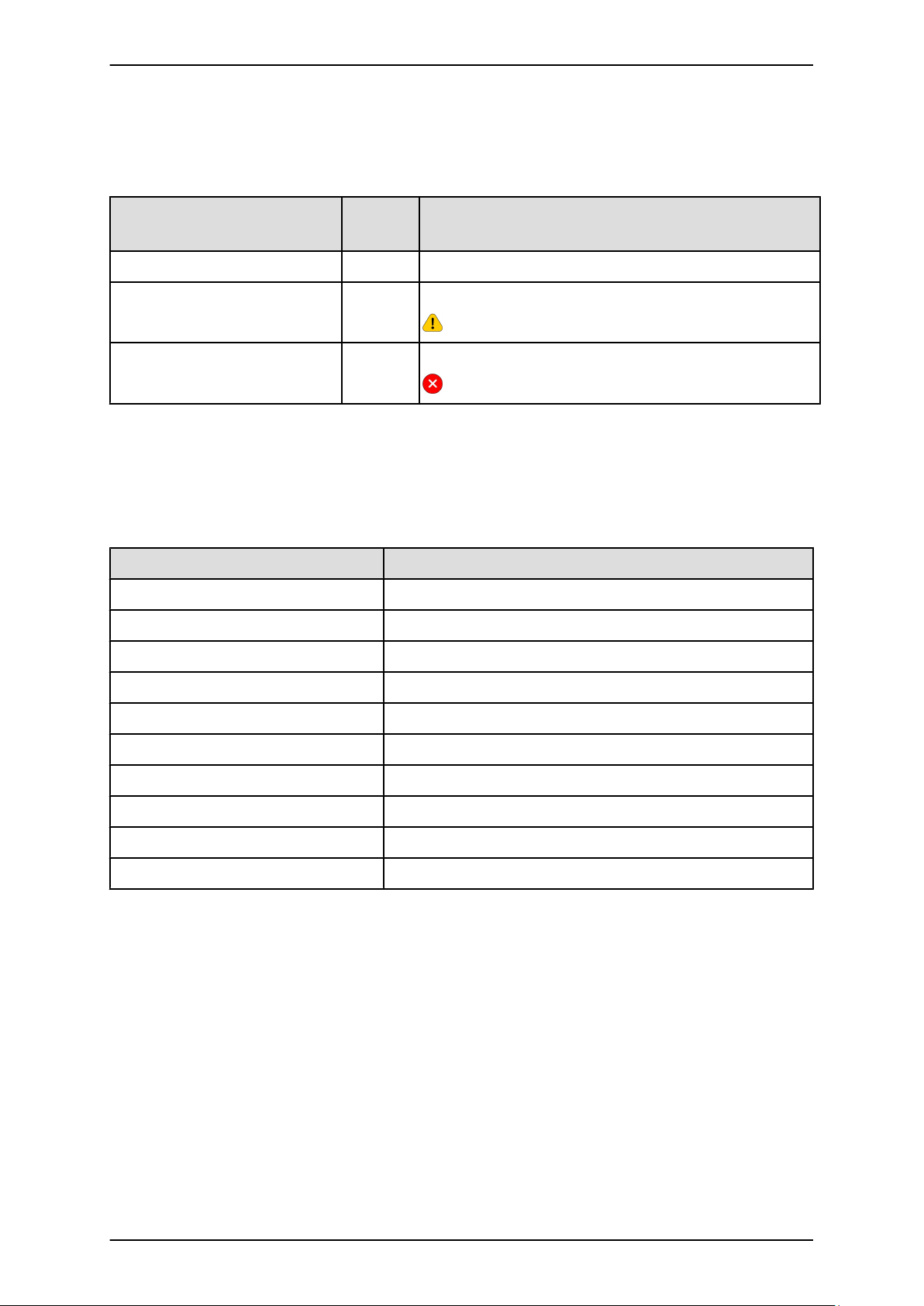
PRIMEQUEST 1000 Series Tool Reference
CHAPTER 1 MMB Web-UI (Web User Interface) Operations
TABLE 1.14 Unit status and displayed icon
Status Display
Icon
color
Normal (normal status) Green None
Warning, Degraded Yellow A black ! mark in a yellow triangle
Failed Red A white x mark in a red circle
Each unit has a link to a window that displays detailed information. However, there are no links to unmounted units
since there are no corresponding detail windows.
TABLE 1.15 Display items in the [System Status] window
Item Description
Power Supply Displays the PSU status.
Fans Displays the fan status.
Temperature Displays the temperature sensor status.
SB#0 to SB#3 Displays the system board status.
IOB#0 to IOB#1 Displays the IOB status.
GSPB#0 to GSPB#1 Displays the GSPB status.
SASU#0 to SASU#3 Displays the SAS disk unit status.
DVDB Displays the DVDB status.
MMB#0 to MMB#1 Displays the MMB status.
PCI_Box#0 to PCI_Box#1 Displays the connected PCI_Box status.
(1) Menu operations
[System] - [System Status]
(2) Window operations
1. Click the corresponding link for a unit to check the details of the unit status.
The window that appears displays the details of the unit status.
Remarks
You can also directly select the menu item for a unit from a [System] submenu to display the details of the unit
status. For details on the procedure, see 1.2.9 [LEDs] window to 1.2.17 [PCI_Box] menu.
59 C122-E110-10EN
Page 92
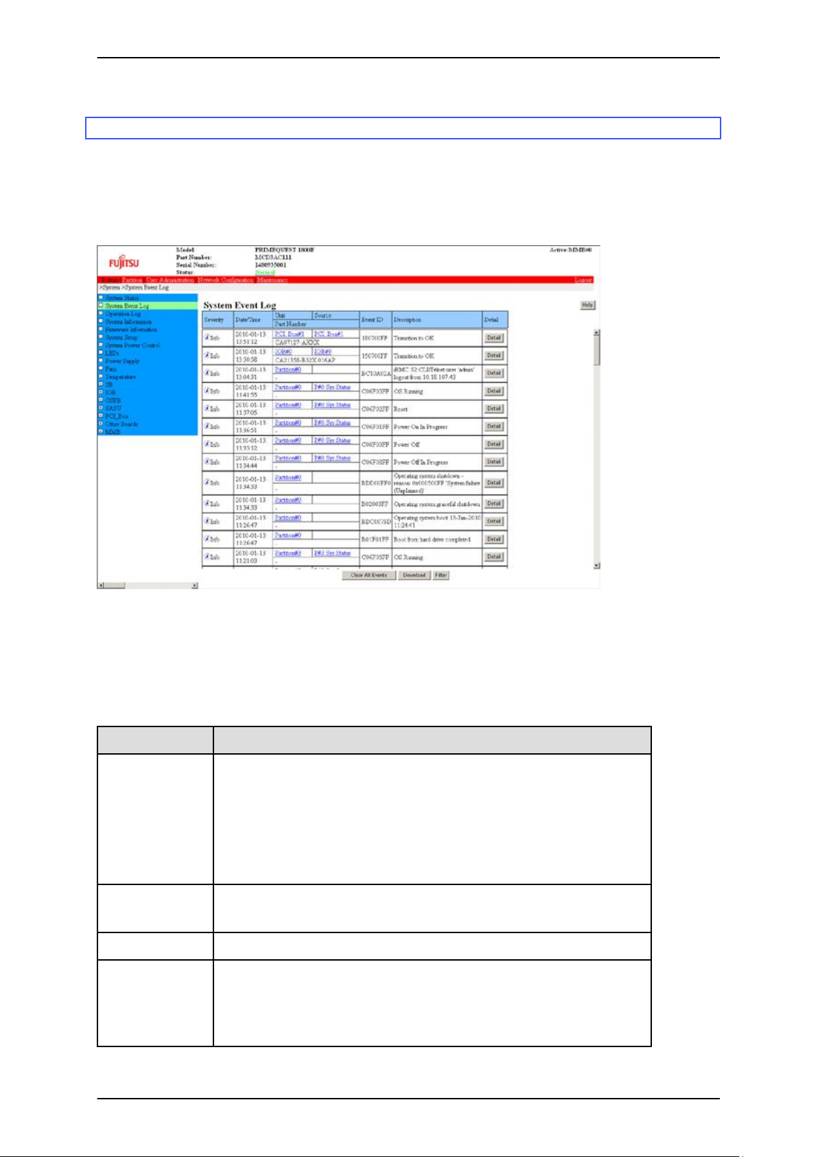
PRIMEQUEST 1000 Series Tool Reference
CHAPTER 1 MMB Web-UI (Web User Interface) Operations
1.2.2 [System Event Log] window
The [System Event Log] window displays MMB and BMC events that occurred in the PRIMEQUEST 1000 series
system. The window displays the events currently stored in the system event log of the MMB in order of time.
The system event log can store up to 32,000 events. When the system event log file is full, the oldest record is
deleted and replaced with the latest one.
FIGURE 1.2 [System Event Log] window
You can scroll table contents in the [System Event Log] window. The table headers scroll with you.
If there are no events to display, the message "There are no Event Logs" appears instead of the table.
TABLE 1.16 Display items in the [System Event Log] window
Item Description
Severity Displays the severity of the event or error.
- Error: Serious problem such as a hardware failure
- Warning: Event that is not necessarily serious but is a potential problem
in the future
- Info: Event such as a partition power-on, reported for informational
purposes.
Date/Time Displays the local time of occurrence of the event or error.
Format: YYYY-MM-DD HH:MM:SS
Source Displays the name of the sensor indicating the occurrence of the event or error.
Unit Displays the unit containing the sensor on which the event or error occurred.
For example, if an error occurs at CPU#0 on SB#0, this item will display [SB#0].
The unit is identified from the entity ID of the sensor in a search for the FRU in
control of the sensor. The parent entity is retrieved from the Entity Association
60 C122-E110-10EN
Page 93
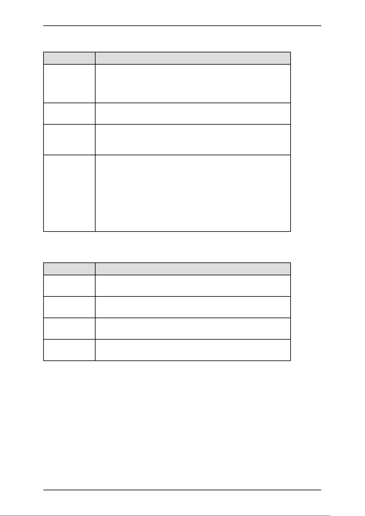
PRIMEQUEST 1000 Series Tool Reference
CHAPTER 1 MMB Web-UI (Web User Interface) Operations
Item Description
Record. The displayed name is the Board/Unit Name written in the FRU Record
of the parent entry.
Each unit has a link to a window that displays the details of the unit status. (You
can see the part number and serial number of the unit in that window.)
Part Number Displays the part number stored in the system event log.
If no part number is stored, this field displays "-".
Event ID Displays an ID (8 digits, hexadecimal) that identifies the nature of the event
For details on Event ID assignment, see Chapter 2 MMB Messages in the
PRIMEQUEST 1000 Series Message Reference (C122-E111EN).
Description Displays the details of the event or error.
If the sensor recorded data other than Trig Offset in Event Data, this column
displays the event data. For example, the R and T values recorded by the sensor
are displayed as the Reading Value and Threshold Value at the event occurrence
time.
Remarks
For an event related to the mounting or removal of a board, the part number and
serial number of the board is displayed.
TABLE 1.17 Buttons in the [System Event Log] window
Button Description
Clear All Events Click the [Clear All Events] button to clear all the events stored in the system
event log. Use this button only when instructed by a field engineer.
Download After a confirmation message appears, the [System Event Log (Collect)]
window appears.
Filter Click the [Filter] button to display the [System Event Log Filtering Condition]
window. You can enter filtering conditions in that window.
Detail Click the [Detail] button to display details of the corresponding event in the
[System Event Log (Detail)] window.
(1) Menu operations
[System] - [System Event Log]
(2) Window operations
- Downloading the event data stored in the system event log (if no collected system event log is found)
1. Click the [Download] button.
The [I_00417 Are you sure?] message appears. Click the [OK] button.
2. Collection of system event log information starts automatically. The [Progress] window appears.
3. The [System Event Log (Collect)] window appears. The displayed date information includes a link to
the collected event data. Click the link. A dialog box appears. Specify the file name and the path. Then,
download the event data to the computer displaying the Web-UI.
61 C122-E110-10EN
Page 94
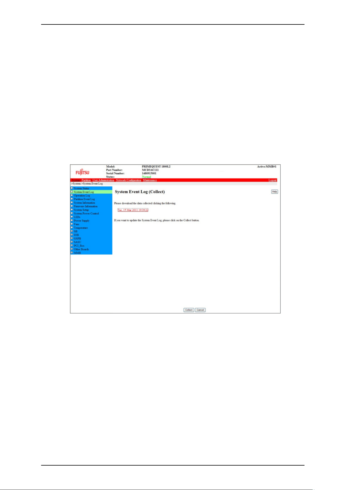
PRIMEQUEST 1000 Series Tool Reference
CHAPTER 1 MMB Web-UI (Web User Interface) Operations
- Downloading the event data stored in the system event log (if a collected system event log is found)
1. Click the [Download] button.
The [I_00417 Are you sure?] message appears. Click the [OK] button.
2. The [System Event Log (Collect)] window appears. The window displays a link to the collected system
event log information.
3. To acquire the latest system event log information, click the [Collect] button. The [I_00417 Are you
sure?] message appears. Click the [OK] button. The [Progress] window is displayed while system event
log information is collected.
4. The [System Event Log (Collect)] window appears. The displayed date information includes a link to
the collected event data. Click the link. A dialog box appears. Specify the file name and the path. Then,
download the event data to the computer displaying the Web-UI.
FIGURE 1.3 [System Event Log (Collect)] window
- Narrowing down the events displayed in the window
1. Click the [Filter] button.
The [System Event Log Filtering Condition] window for entering filtering conditions appears.
2. Enter the conditions in the [System Event Log Filtering Condition] window. Then, click the [Apply]
button.
The browser returns to the [System Event Log] window. The window displays the events satisfying
the specified conditions.
- Displaying the details on events displayed in the window
1. Click the [Detail] button.
The [System Event Log (Detail)] window appears. The window displays details of the event.
[System Event Log Filtering Condition] window
62 C122-E110-10EN
Page 95
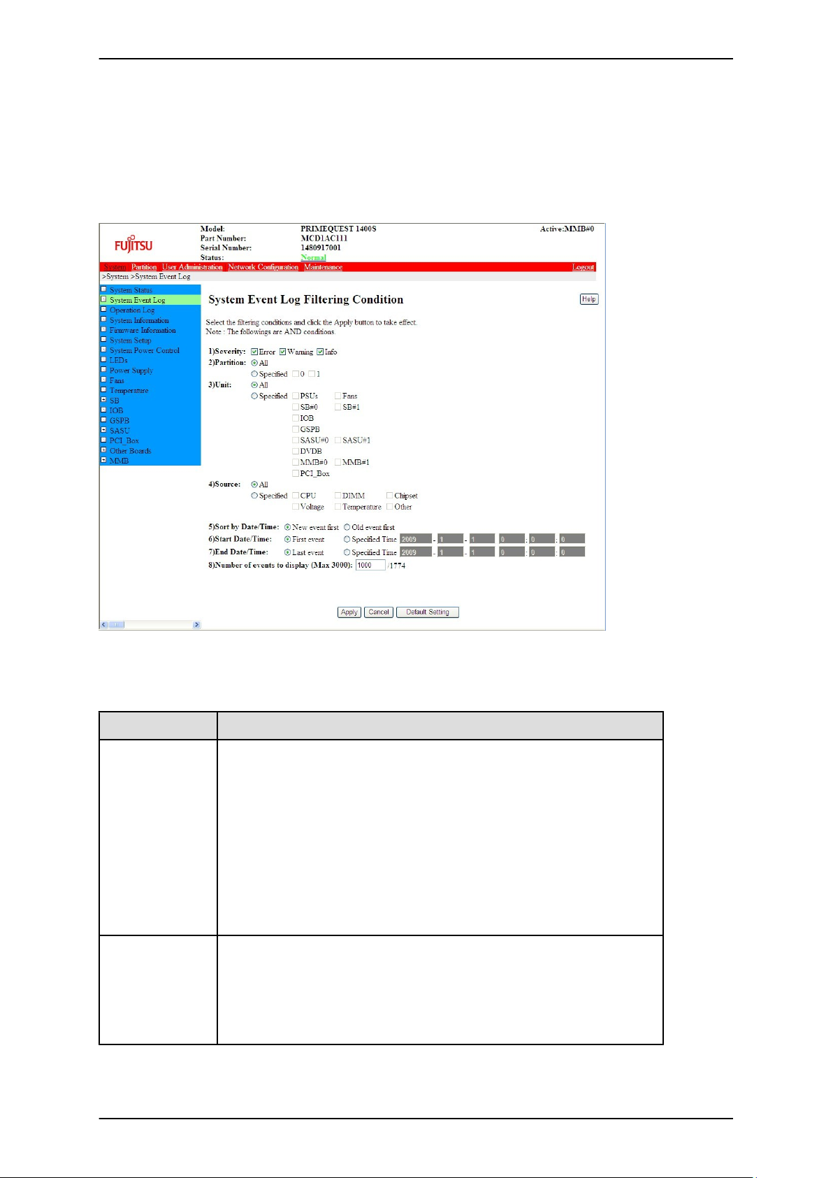
PRIMEQUEST 1000 Series Tool Reference
CHAPTER 1 MMB Web-UI (Web User Interface) Operations
In the [System Event Log] window, click the [Filter] button to display the [System Event Log Filtering Condition]
window. You can enter filtering conditions in this window.
In the [System Event Log Filtering Condition] window, you can specify a filtering condition for events to be
displayed in the [System Event Log] window.
FIGURE 1.4 [System Event Log Filtering Condition] window
TABLE 1.18 Setting and display items in the [System Event Log Filtering Condition] window
Item Description
Severity Check the check box for the severity level to be displayed. Multiple options can
be selected.
- Error
- Warning
- Info
- Monitor
Everything is selected by default.
Note
The [Monitor] check box appears only if you logged in with CE privileges.
Partition Specify the partitions to be displayed.
The selected radio button is either [All] or [Specified].
- All: Filtering by partition is not applied.
- Specified: Filtering by partition can be set. Check the check boxes for the
partitions to be displayed.
63 C122-E110-10EN
Page 96

PRIMEQUEST 1000 Series Tool Reference
CHAPTER 1 MMB Web-UI (Web User Interface) Operations
Item Description
For users with Partition Operator privileges, [All] is grayed out and not
available. For partition filtering, only the partition under their management can
be selected.
By default, [All] is selected for users without Partition Operator privileges. For
users with Partition Operator privileges, [Specified] and the managed partitions
are selected by default.
Source Select the source to be displayed.
The selected radio button is either [All] or [Specified].
- All: Filtering by [Source] is not applied.
- Specified: Filtering by source can be set. Check the check boxes of the
sources to display.
The default is [All].
Unit Select the unit to be displayed.
The selected radio button is either [All] or [Specified].
- All: Filtering by unit is not applied.
- Specified: Filtering by unit can be set. Check the check boxes of the
sources to display.
The default is [All].
Sort by Date/Time Specify whether to list log messages in chronological order or reverse
chronological order, by selecting the appropriate radio button.
- New event first
- Old event first
The default is [New event first].
Start Date/Time Specify whether to list log messages with the first event or at a specified time,
by selecting the appropriate radio button.
- First event: Time of the first event
- Specified Time: Specified date and time. If you select [Specified Time],
enter the start time (year, month, day, hour, and minute).
The default is [First event].
End Date/Time Specify whether to end the display with the last event or at a specified time, by
selecting the appropriate radio button.
- Last event: Time of the last event
- Specified Time: Specified date and time. If you select [Specified Time],
enter the end time (year, month, day, hour, and minute).
The default is [Last event].
Number of events to
display
Specify the number of logs to be displayed. The denominator represents the total
number of logged events. The maximum specifiable value is 3000.
The default is 100.
64 C122-E110-10EN
Page 97
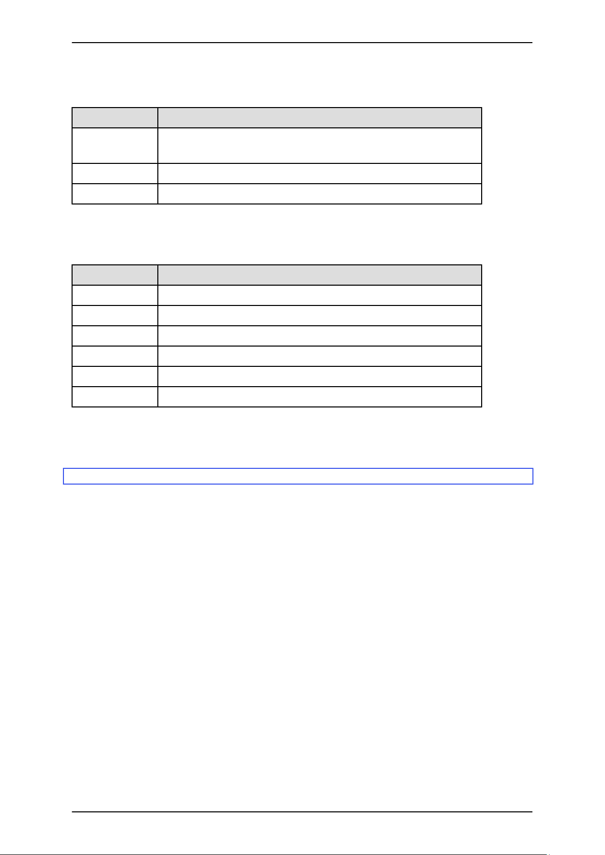
PRIMEQUEST 1000 Series Tool Reference
CHAPTER 1 MMB Web-UI (Web User Interface) Operations
TABLE 1.19 Buttons in the [System Event Log Filtering Condition] window
Button Description
Apply Click the [Apply] button to list those logs that match the specified conditions in
the [System Event Log] window.
Cancel Click the [Cancel] button to return to the [System Event Log] window.
Default Setting Resets settings to their default values.
Messages
The following table lists the messages displayed in this window.
Message number Message text
W_00413 Nothing is selected.
W_00414 Invalid Date Format
W_00434 Invalid Time Format
W_00441 Range over error.
I_00417 Are you sure?
I_00468 Are you sure you want to clear the SEL?
For details on messages displayed in the window, see the PRIMEQUEST 1000 Series Message Reference (C122E111EN).
1.2.3 [Operation Log] window
The [Operation Log] window displays logs on the settings and operations of the Web-UI and CLI.
Each operation log includes login information about the source of an operation (e.g., Web-UI/CLI, IP address,
account).
65 C122-E110-10EN
Page 98
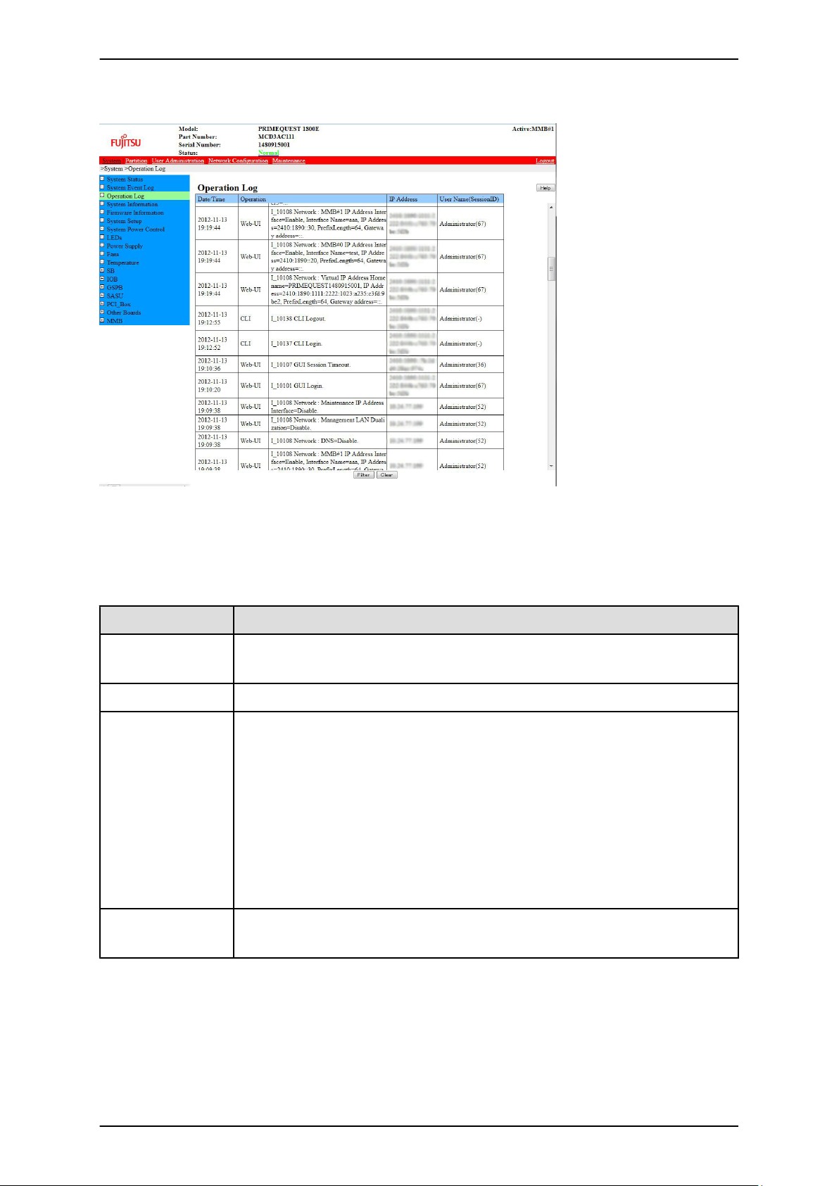
PRIMEQUEST 1000 Series Tool Reference
CHAPTER 1 MMB Web-UI (Web User Interface) Operations
FIGURE 1.5 [Operation Log] window
You can scroll table contents in the [Operation Log] window. The table headers scroll with you.
TABLE 1.20 Display items in the [Operation Log] window
Item Description
Date/Time Displays the local time of occurrence of the event or error.
Format: YYYY-MM-DD HH:MM:SS
Operation Displays the source (Web-UI or CLI) and contents of the operation.
IP Address Displays the source IP address (IPv4 or IPv6 address) of the operation.
This column displays [Console] for a CLI operation performed on a console with serial
connection.
If the host name can be identified from the DNS set on the MMB at the login time, this
field displays the host name. Otherwise, it displays the IP address.
If the user is logged in from the Web-UI, the field displays only the IP address using the
DNS.
If the logged-in user is using the IPv6 address connection, the field displays only the IP
address using the DNS.
User Name
(Session ID)
Displays the operator's name and session ID for Web-UI operations.
The session ID for CLI operations is displayed as "-".
66 C122-E110-10EN
Page 99
PRIMEQUEST 1000 Series Tool Reference
CHAPTER 1 MMB Web-UI (Web User Interface) Operations
TABLE 1.21 Buttons in the [Operation Log] window
Button Description
Filter Click the [Filter] button to display the [Operation Log Filtering Condition] window. You
can enter filtering conditions in that window.
Clear Click the [Clear] button to clear all the operation logs.
(1) Menu operations
[System] - [Operation Log]
(2) Window operations
- Clearing all the operation logs
1. Click the [Clear] button.
A confirmation dialog box appears.
2. Click the [OK] button to clear the operation logs.
Click the [Cancel] button to cancel clearing of the operation logs.
- Narrowing down the operation logs displayed in the window
1. Click the [Filter] button.
The [Operation Log Filtering Condition] window for entering filtering conditions appears.
2. Enter the conditions in the [Operation Log Filtering Condition] window. Then, click the [Apply] button.
The browser returns to the [Operation Log] window. The window displays the logs satisfying the
specified conditions.
[Operation Log Filtering Condition] window
In the [Operation Log] window, click the [Filter] button to display the [Operation Log Filtering Condition] window.
You can enter filtering conditions in this window.
In the [Operation Log Filtering Condition] window, you can specify a filtering condition for events to be displayed
in the [Operation Log] window.
67 C122-E110-10EN
Page 100
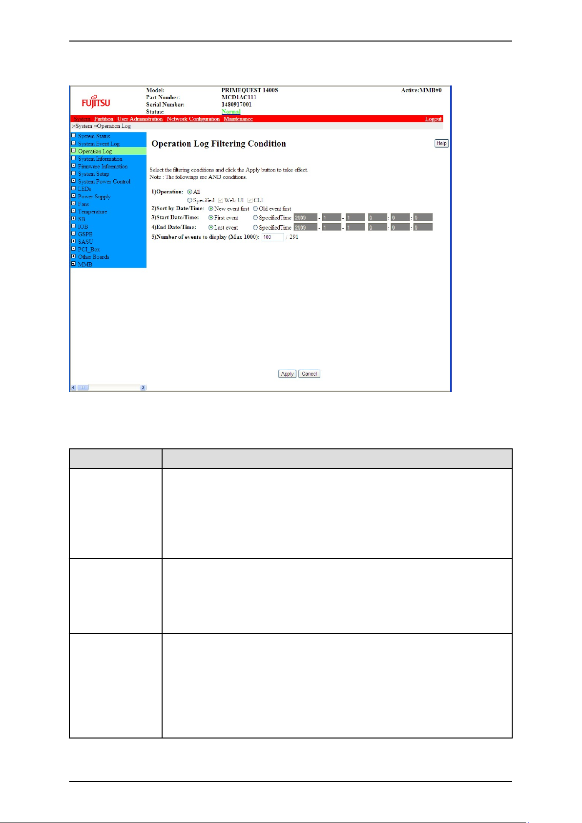
PRIMEQUEST 1000 Series Tool Reference
CHAPTER 1 MMB Web-UI (Web User Interface) Operations
FIGURE 1.6 [Operation Log Filtering Condition] window
TABLE 1.22 Setting and display items in the [Operation Log Filtering Condition] window
Item Description
Operation Select the operation to be displayed.
The selected radio button is either [All] or [Specified].
- All: Filtering by operation is not applied.
- Specified: Filtering by operation can be set. Check the check box for the operation
to be displayed.
The default is [All].
Sort by Date/Time
Specify whether to list log messages in chronological order or reverse chronological order,
by selecting the appropriate radio button.
- New event first
- Old event first
The default is [New event first].
Start Date/Time
Specify whether to list log messages with the first event or at a specified time, by selecting
the appropriate radio button.
- First event: Time of the first event
- Specified Time: Specified date and time
If you select [Specified Time], enter the start time (year, month, day, hour, and
minute).
The default is [First event].
68 C122-E110-10EN
 Loading...