

Fujitsu PLASMAVISION P55XHA51WS, PLASMAVISION P42VHA51WS, PLASMAVISION P42HHA51WS, PLASMAVISION P50XHA51WS User Manual
Page 1
USER'S MANUAL
(Specification and Part Names)
WIDE PLASMA DISPLAY
P42VHA51W
P42HHA51W/P50XHA51W/P55XHA51W
P42HHA51A/P50XHA51A/P55XHA51A
EnglishDeutschEspañolFrançaisItalianoPortuguês
Contents
Page
Before Use
• INFORMATION......................................................................................................... E-2
• INSTALLATION ........................................................................................................ E-3
Usage
• PART NAMES AND FUNCTIONS............................................................................ E-4
Others
• OPTIONS.................................................................................................................. E-8
• MAIN SUPPORTED SIGNALS................................................................................. E-9
• SPECIFICATIONS .................................................................................................. E-10
Before using the display, read the User’s manual (1/2) and the User’s manual (2/2) carefully so that you know how to use the display
correctly.
Refer to this manual whenever questions or problems about operation arise. Be sure to read and observe the safety precautions (see
the separate "Safety Precautions" manual).
Keep this manual where the user can see it easily.
* Installation and removal require special expertise. Consult your product dealer for details.
* When "English" is selected at "Language" of the on-screen display, "colour" will be displayed but "color" is described in this manual.
* The residential warranty for "A model" is enclosed in accessories.
* The last digit of MODEL NO. (10 digit alphanumeric characters) indicated on the product means the body color indication alphabet or
the management number.
* The illustration of external appearance is for 42" model.
Please acknowledge some differences in the actual product of other models.
Pусский
÷–Œƒ
日 本 語
Page 2
INFORMATION
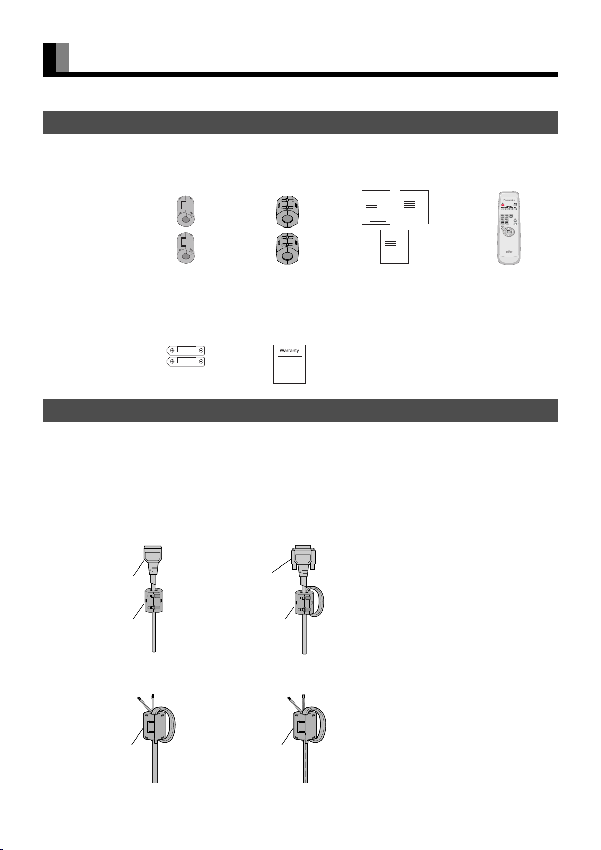
CHECKING ACCESSORIES
One power cable
Two sm all
ferrite cores
No.:ZCAT1518-0730
Mfr.:TDK
Two AA batteries
Two big
ferrite cores
No.:SFT-72SN
Mfr.:TKK
One residential
warranty
(for the A model)
Manual
One remote control Three user's manuals
Manual
Manual
ATTACHING THE FERRITE CORES
The ferrite cores are used to reduce noise. Attach them correctly as shown in the following illustrations.
Be sure to turn off power of the plasma display and external equipment before making any connections.
Carefully check the terminals for position and type before making any connections.
Loose connectors can result in picture or color problems. Make sure that all connectors are securely inserted into their terminals.
Two big ferrite cores
When connecting the cord to the power input terminal, RS232C input terminal, attach one of these ferrite cores to the cord and the cable
near the terminal.
Power Cord
Ferrite Core
RS232C Cable
Ferrite Core
Two small ferrite cores
When connecting a cable to the external speaker output terminal attach one of these ferrite cores to the cable near the terminal.
Ferrite Core
Ferrite Core
E-2
Page 3

INSTALLATION
To prevent the plasma display's internal components from overheating, make sure that the plasma display is installed in a well-ventilated
location.
Be sure to use the optional stand, wall-mounting unit or the other mounting unit when installing the plasma display. Also, be sure that your
dealer performs the installation.
See the appropriate instruction manual for additional information on the mounting hardware you select.
To prevent an accident and ensure safety in the event of an earthquake, fix the plasma display securely into the position as described below.
Use the diagram below to determine how much space is needed to ensure proper heat radiation. This is a minimum space requirement;
therefore, provide at least as much space as indicated below.
* Make sure that the plasma display is installed in a location where the temperature can be maintained between 0°C and 40°C (between
32°F and 104°F)
* Never attempt to tilt the plasma display sideways or backward.
* To prevent the power cord and other cables from being accidentally pulled, make sure that they run along the wall or through corners.
* To prevent accidents and ensure safety in the event of an earthquake, secure the plasma display to prevent it from tipping over.
Display Section
Front Side
EnglishDeutschEspañolFrançaisItalianoPortuguês
Left
Upper
10
10
5
Lower
10
Right
(cm)
3.5 (for 42"/50")
5 (for 55")
(cm)
Wall
Pусский
Note
• The external view is meant to be a representation of the actual unit and is not to scale; therefore, it may differ from the actual shape and size of the
product.
• Due to the fragile and highly precise equipment, it is very important to pack properly before transportation using only the packing materials
provided.
Reference
See P. E-8 for more information on options.
÷–Œƒ
日 本 語
E-3
Page 4
PART NAMES AND FUNCTIONS
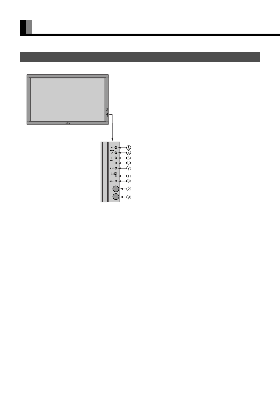
DISPLAY SECTION – FRONT
(Right section)
Power indicator lamp
This lamp shows the state of the power supply.
Lit (red): Stand-by state
Lit (green): Power ON state
Flashing (red or green): Malfunction (Flashes differently
depending on the type of
malfunction.)
Remote control signal receiver
Receives signals from the remote control.
Input mode selector button
Input mode selector button
Switches between picture input modes.
Vol u m e + bu t t o n
Volume - button
Adjusts the audio volume.
Wide screen selector button
Switches the screen over to a desired wide screen.
ON/OFF button
Turns the power "ON" and "OFF (standby state)".
Ambient Sensor
Detects the brightness of external light.
Do not obstruct it.
Warning
If the power indicator lamp flashes red or green, this signifies that the display has developed a problem. When this happens, be sure to remove the
power plug from the receptacle and contact your dealer. Leaving the display power ON can result in fire or electric shock.
E-4
Page 5
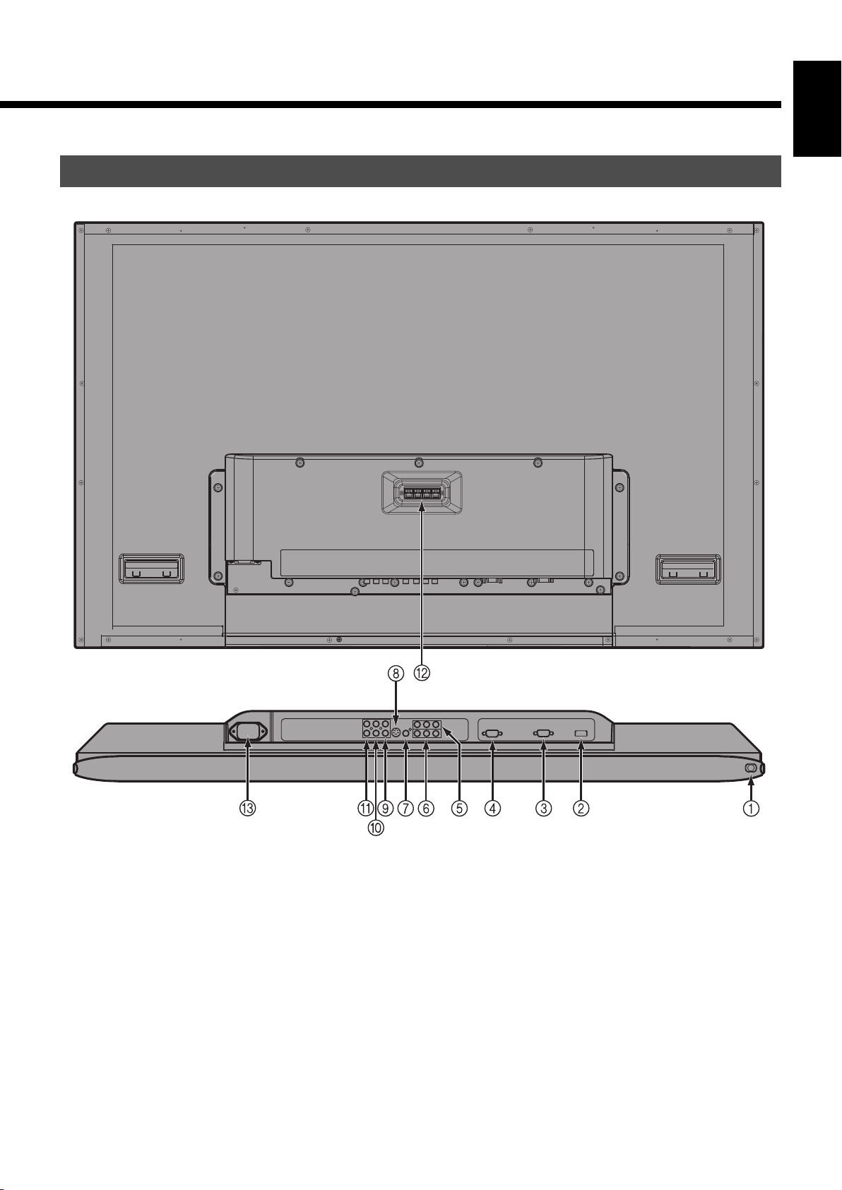
DISPLAY SECTION – BACK AND BOTTOM PART
EnglishDeutschEspañolFrançaisItalianoPortuguês
/ I power switch
If this button is pressed when the power indicator lamp is off, the indicator lamp will light.
The power can be turned on and the standby mode selected by using the remote control or the control panel of the display.
If this button is pressed when the power indicator lamp is lit, the indicator lamp will go out.
*Power is still supplied to parts of the display even if the indicator lamp is off.
HDMI input terminal (VIDEO5 INPUT/HDMI)
Connect this terminal to the HDMI output terminal for DVD, etc.
RS-232C terminal (RS-232C)
This terminal is provided for you to control the display from the PC. Connect it to the RS-232C terminal on the PC.
When connecting a cable, attach a ferrite core to the cable. (See P. E-2.)
Note
• The illustration of external appearance is for 42" model. Please acknowledge some differences in the actual product of other models.
Pусский
÷–Œƒ
日 本 語
E-5
Page 6

PART NAMES AND FUNCTIONS (Continued)
RGB1 input terminal (RGB1 INPUT/mD-sub)
Connect this terminal to the PC’s display (analog RGB) output terminal or decoder (digital broadcast tuner, etc.) output terminal.
Component video input terminal (VIDEO3 INPUT)
Component video input terminal (VIDEO4 INPUT)
Connect this terminal to the component video output (color difference output) terminal of your HDTV unit or DVD player.
Video input terminal (VIDEO1 INPUT)
Connect this terminal to the video output terminal of your VCR.
S-Video input terminal (VIDEO2 INPUT)
Connect this terminal to the S-video output terminal of your VCR.
Audio3 input terminal (AUDIO3 INPUT)
Audio2 input terminal (AUDIO2 INPUT)
Audio1 input terminal (AUDIO1 INPUT)
Connect this terminal to the audio output terminal of your VCR, etc. (See the User’s manual (2/2) for the selection of audio input for video
input.)
External speaker output terminal (EXT SP)
Connect this terminal to the optionally available speaker.
When connecting a cable, attach a ferrite core to the cable. (See P. E-2.)
* See the speaker instruction manual for more information.
" Power input terminal
Connect this terminal to the power cable supplied with the display.
When connecting a cable, attach a ferrite core to the cable. (See P. E-2.)
E-6
Page 7
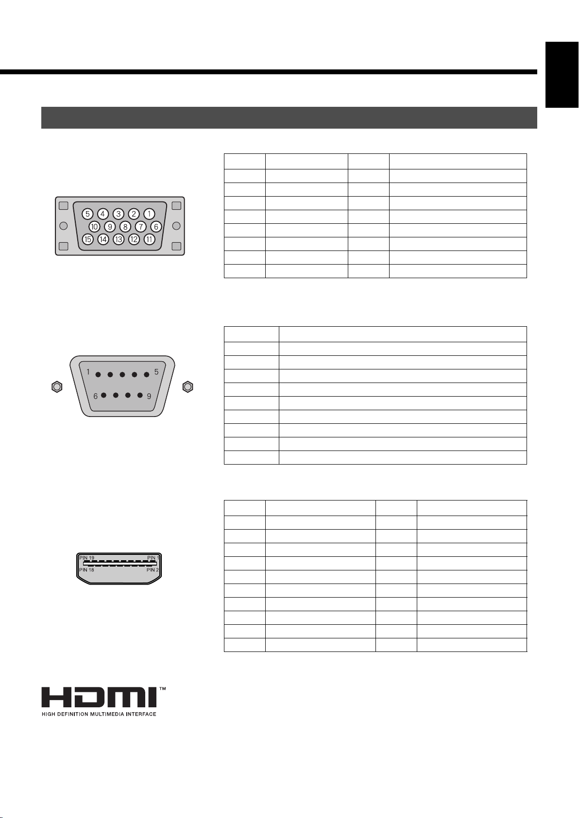
DESCRIPTION OF INPUT TERMINALS
EnglishDeutschEspañolFrançaisItalianoPortuguês
mD-sub input terminal
(RGB1 INPUT/mD-sub)
RS-232C terminal (RS-232C)
Pin No. Input signal Pin No. Input signal
1Red 9—
2 Green 10 Ground
3Blue 11—
4— 12—
5 Ground 13 Horizontal synchronization
6 Ground 14 Vertical synchronization
7 Ground 15 —
8 Ground Frame Ground
Pin No. Signal
1 DCD (Data Carrier Detect)
2 RD (Received Data)
3 TD (Transmit Data)
4 DTR (Data Terminal ready)
5 GND (Ground)
6 DSR (Data Set Ready)
7 RTS (Request To send)
8 CTS (Clear To Send)
9 RI (Ring Indication)
HDMI input terminal (VIDEO5 INPUT/HDMI)
HDMI, the HDMI logo and High-Definition Multimedia interface are trademarks or registered
trademarks of HDMI Licensing LCC.
Pin No. Input signal Pin No. Input signal
1 T.M.D.S. Data2+ 11 T.M.D.S. Clock Shield
2 T.M.D.S. Data2 Shield 12 T.M.D.S. Clock–
3 T.M.D.S. Data2– 13 CEC
4 T.M.D.S. Data1+ 14 Reserve
5 T.M.D.S. Data1 Shield 15 DDC Clock
6 T.M.D.S. Data1– 16 DDC Data
7 T.M.D.S. Data0+ 17 Ground (for +5V)
8 T.M.D.S. Data0 Shield 18 +5V Power
9 T.M.D.S. Data0– 19 Hot Plug Detect
10 T.M.D.S. Clock+ Frame FG
Pусский
÷–Œƒ
日 本 語
E-7
Page 8

OPTIONS
Wall-mounting Bracket 0° to 15° mounting angle P-WB4201 (for 42” model/50” model)
P-WB6300 (for 55” model)
Ceiling unit 5° to 25° mounting angle P-CT4200 (for 42” model/50” model)
P-CT6300 (for 55” model)
Desktop Stand unit P-TT4202 (for 42” model/50” model/55”
model)
Speaker
(1 set of 2 speakers)
Desktop Speaker Stand
(1 set of 2 speaker stands)
* When installing an option, make sure that all installation requirements for that option (as given in the relevant instruction manual) are met.
* The colors of options do not match the display colors perfectly.
* To improve the function and performance of optional accessories, specifications and part names may change. Consult your local dealer
before purchasing.
Warning
To prevent injury, fire, and electric shock, arrange for options to be initially installed (or installed at a different location) by your dealer.
P-SP1000 (for attaching to the display) for
42” model/50” model
P-SP5010 (for attaching to the display) for
55” model
P-SP4200 (for mounting on the speaker
stands) for 42” model
P-SP5010 (for mounting on the speaker
stands) for 50” model/55” model
P-ST4200 (for P-SP4200)
P-ST5000 (for P-SP5010)
CAUTION
This display (P42VHA51/P42HHA51/P50XHA51) is for use only with Fujitsu General Limited's option (P-WB4201, P-CT4200, P-TT4202).
This display (P55XHA51) is for use only with Fujitsu General Limited's option (P-WB6300, P-CT6300, P-TT4202).
Using this display with other option can cause instability resulting in possible injury.
E-8
Page 9
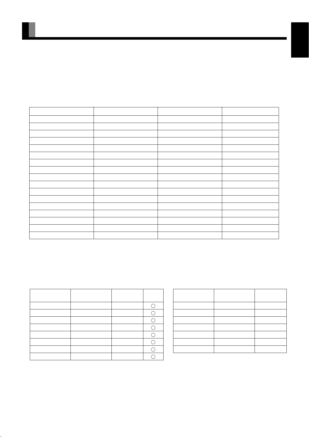
MAIN SUPPORTED SIGNALS
This display can store the latest four types of signals for RGB adjustment value. The fifth input signal will replace the adjustment value of
the first input signal.
To do this, select a desired signal and follow the instructions in “Adjusting Screen Position and Size” on the User’s manual (2/2) to adjust
the parameters.
When you finish, the settings will be automatically stored. Thus, when the display receives that signal, pictures will be displayed in
accordance with the settings you most recently selected.
Main corresponding signals (RGB mode)
Display (dots x lines)
640 x 480 31.47 59.94 VGA
640 x 480 37.50 75.00 VGA 75 Hz
640 x 480 43.27 85.01 VGA 85 Hz
720 x 400 31.47 70.09 400 lines
800 x 600 37.88 60.32 SVGA 60 Hz
800 x 600 46.88 75.00 SVGA 75 Hz
800 x 600 53.67 85.06 SVGA 85 Hz
1024 x 768 48.36 60.00 XGA 60 Hz
1024 x 768 60.02 75.03 XGA 75 Hz
1024 x 768 68.68 84.99 XGA 85 Hz
1280 x 1024 63.98 60.02 SXGA 60 Hz ※
1280 x 1024 79.98 75.03 SXGA 75 Hz ※
848 x 480 31.02 60.00
852 x 480 31.72 59.97
1360 x 768 47.71 60.01
720 x 485 15.73 59.94 60 fields
720 x 575 15.63 50.00 50 fields
Horizontal frequency (kHz)
Vertical frequency (Hz) Signal
EnglishDeutschEspañolFrançaisItalianoPortuguês
* With some input signals, "Out of range" may appear even when the horizontal and vertical frequencies are within their permissible
ranges. In this event, match the input signals to another frequency rather than those listed above.
※It doesn't support the model with 42" display (displayed pixels 852 x 480 dots x lines).
In the Comp.video and Video/S-video, the display has been factory-set as follows for different input signals:
Main corresponding signals (Comp.video mode) Main corresponding signals (Video, S-video mode)
Horizontal
frequency (kHz)
15.73 59.94 SDTV 480i 15.73 59.94 NTSC
15.63 50.00 SDTV 576i 15.63 50.00 PAL
31.47 59.94 SDTV 480p 15.63 50.00 SECAM
31.25 50.00 SDTV 576p 15.63 59.52 PAL60
45.00 60.00 HDTV 720p 15.63 50.00 N-PAL
37.50 50.00 HDTV 720p 15.73 59.95 M-PAL
33.75 60.00 HDTV 1080i 15.73 59.94 4.43NTSC
28.13 50.00 HDTV 1080i
Note
• Depending on the input signal, the display may show pictures of reduced size due to size reduction and interpolation.
• You can check input signals through "Information" on the FEATURES Menu screen (See User's Manual (2/2)).
• In order to facilitate the explanations, pictures and diagrams in this manual may differ slightly from the actual items.
• All terms (i.e., company and product names) used in this document are trademarks or registered trademarks.
Ver tical
frequency (Hz)
Signal HDMI
Horizontal
frequency (kHz)
Vertical
frequency (Hz)
Signal
Pусский
÷–Œƒ
日 本 語
E-9
Page 10

SPECIFICATIONS
WIDE PLASMA DISPLAY
Model P42VHA51W P42HHA51W/A P50XHA51W/A P55XHA51W/A
Screen size
Aspect ratio 16:9 (wide)
Number of pixels 852 (H) x 480 (V) 1024 (H) x 1024 (V) 1366 (H) x 768 (V)
Weight 31.5 kg / 69 lbs 45 kg / 99 lbs 52 kg / 114.5 lbs
Outer dimensions 103.9 (W) x 64.0 (H) x 8.7 (D) cm
Power supply 110-240 VAC 50/60 Hz
Current rating 3.4-1.45 A 4.0-1.45 A 4.85-1.95 A 5.4-2.1 A
External equipment terminals
Video input
terminals
PC input terminal RGB1 input mD-sub, 3 rows, 15-pin
Audio terminals 2 audio input pin jacks (L/R) (3 lines)
Control terminal RS-232C connector (D-sub 9-pin)
External speaker
output terminal
Operating
conditions
Accessories
42" wide screen:
92.1 cm (W) x 51.8 cm (H)
(105.7 cm diagonal)
36.3 inch (W) x 20.4 inch (H)
(41.6 inch diagonal)
40.9 (W) x 25.2 (H) x 3.4 (D) inch
(does not include outer projections)
VIDEO1 INPUT (Video input) RCA terminal 1 Vp-p/75 Ω
VIDEO2 INPUT (S-video input) S terminal Y: 1 Vp-p/75 Ω
VIDEO3/VIDEO4 INPUT 3 RCA terminals Y: 1 Vp-p/75 Ω
(Component video input) P
VIDEO5 INPUT (HDMI input) HDMI terminal (HDMI type A connector)
500 mVrms/at least 22 kΩ
Max. output: 10 W + 10 W, 6 Ω
Temperature: 0 to 40 °C / 32 to 104 °F
Humidity: 20 to 80 %
3 user's manuals, 1 power cable, 2 small ferrite cores, 2 big ferrite cores, 1 remote control, 2 AA batteries, 1 residential
warranty (for the A model)
42" wide screen:
92.2 cm (W) x 52.2 cm (H)
(106.0 cm diagonal)
36.3 inch (W) x 20.6 inch (H)
(41.7 inch diagonal)
Picture signal: 0.7 Vp-p/75 Ω
Synchronization signal:TTL level
50" wide screen:
110.6 cm (W) x 62.2 cm (H)
(126.9 cm diagonal)
43.5 inch (W) x 24.5 inch (H)
(50 inch diagonal)
121.6 (W) x 72.6 (H) x
10.0 (D) cm
47.9 (W) x 28.6 (H) x 3.9
(D) inch
(does not include outer
projections)
C: 0.286 Vp-p/75 Ω
B/CB: 0.7 Vp-p/75 Ω
PR/CR: 0.7 Vp-p/75 Ω
55" wide screen:
122.9 cm (W) x 69.1 cm (H)
(140.0 cm diagonal)
48.4 inch (W) x 27.2 inch (H)
(55.1 inch diagonal)
138.0 (W) x 80.8 (H) x
12.5 (D) cm
54.3 (W) x 31.8 (H) x 4.9
(D) inch
(does not include outer
projections)
Regulation
• UL, CSA Safety: UL6500, C-UL
EMC: FCC Part 15 Class B, ICES-003 Class B(CISPR22)
• CE Safety: EN60065
EMC: EN55022 Class B(CISPR22)
EN55024
EN61000-3-2
EN61000-3-3
• AS Safety: IEC60065
EMC: AS/NZS 3548(CISPR22)
Note
• Specifications and external appearance may be change for the sake of improvement.
• Viewing the screen constantly for extended periods can strain your eyes. Be sure to stay at a proper distance (at least 1.6 m or 5.2 feet for 42" / at least
1.9 m or 6.2 feet for 50" / at least 2.1 m or 6.9 feet for 55") from the screen and to look occasionally away while working.
• is a worldwide trademark of Fujitsu General Limited and is a registered trademark in Japan, the U.S.A. and other countries or areas.
E-10
 Loading...