

Page 1

B7FY-1651-01
LAN ドータカード取扱説明書
1Gbit/s Ethernet I/O Module User’s Guide
(PG-LND101)
J
E
Page 2

はじめに
このたびは、弊社の LAN ドータカード(以降、本製品)をお買い上げいただき、誠にあ
りがとうございます。
本製品は、弊社のサーバブレードのドータカードスロットに搭載し、LAN(Local Area
Network)システムの構築に使用できます。
本書は、LAN ドータカード、LAN ドライバ(Windows 用)について説明します。ご使用
になる前に、本書をよくお読みになり、正しい取り扱いをされますようお願いいたしま
す。
LAN ドライバについては、サーバブレードに添付されたマニュアル、または富士通パソコ
ン情報サイト FMWORLD.NET の PRIMERGY 向けホームページ(http://www.fmworld.net/
biz/primergy/)を参照してください。
2005 年 11 月
安全にお使いいただくために
本書には、本製品を安全に正しくお使いいただくための重要な情報が記載されています。
本製品をお使いになる前に、本書を熟読してください。特に、本書の「安全上のご注意」をよくお読みにな
り、理解されたうえで本製品をお使いください。
また本書は、本製品の使用中にいつでもご覧になれるよう大切に保管してください。
注 意
この装置は、情報処理装置等電波障害自主規制協議会(VCCI)の基準に基づく第二種情報技術装置です。こ
の装置を家庭環境で使用すると電波妨害を引き起こすことがあります。この場合には使用者が適切な対策を
講ずるよう要求されることがあります。
本製品のハイセイフティ用途での使用について
本製品は、一般事務用、パーソナル用、家庭用、通常の産業用等の一般的用途を想定して設計・製造されて
いるものであり、原子力施設における核反応制御、航空機自動飛行制御、航空交通管制、大量輸送システム
における運行制御、生命維持のための医療器具、兵器システムにおけるミサイル発射制御など、極めて高度
な安全性が要求され、仮に当該安全性が確保されない場合、直接生命・身体に対する重大な危険性を伴う用
途(以下「ハイセイフティ用途」という)に使用されるよう設計・製造されたものではございません。お客
様は、当該ハイセイフティ用途に要する安全性を確保する措置を施すことなく、本製品を使用しないでくだ
さい。ハイセイフティ用途に使用される場合は、弊社の担当営業までご相談ください。
当社のドキュメントには「外国為替および外国貿易管理法」に基づく特定技術が含まれていることがありま
す。特定技術が含まれている場合は、当該ドキュメントを輸出または非居住者に提供するとき、同法に基づ
く許可が必要となります。
2
Page 3
本書の表記
■ 警告表示
本書ではいろいろな絵表示を使っています。これは装置を安全に正しくお使いいただ
き、あなたや他の人々に加えられるおそれのある危害や損害を未然に防止するための
目印となるものです。その表示と意味は次のようになっています。内容をよくご理解
の上、お読みください。
警告
注意
また、危害や損害の内容がどのようなものかを示すために、上記の絵表示と同時に次
の記号を使用しています。
この表示を無視して、誤った取り扱いをすると、人が死亡する可能
性または重傷を負う可能性があることを示しています。
この表示を無視して、誤った取り扱いをすると、人が損害を負う可
能性があること、および物的損害のみが発生する可能性があること
を示しています。
△で示した記号は、警告・注意を促す内容であることを告げるもの
です。記号の中やその脇には、具体的な警告内容が示されています。
で示した記号は、してはいけない行為(禁止行為)であることを
告げるものです。記号の中やその脇には、具体的な禁止内容が示さ
れています。
●で示した記号は、必ず従っていただく内容であることを告げるも
のです。記号の中やその脇には、具体的な指示内容が示されていま
す。
■ キーの表記と操作方法
本文中のキーの表記は、キーボードに書かれているすべての文字を記述するのではな
く、説明に必要な文字を次のように記述しています。
例:【Ctrl】キー、【Enter】キー、【→】キーなど
また、複数のキーを同時に押す場合には、次のように「+」でつないで表記していま
す。
例:【Ctrl】+【F3】キー、【Shift】+【↑】キーなど
■ 本文中の記号
本文中に記載されている記号には、次のような意味があります。
記号 意味
お使いになる際の注意点や、してはいけないことを記述していま
す。必ずお読みください。
ハードウェアやソフトウェアを正しく動作させるために必要なこと
が書いてあります。必ずお読みください。
→ 参照ページや参照マニュアルを示しています。
J
3
Page 4

■ 製品の呼び方
本文中の製品名称を次のように略して表記します。
®
Microsoft
Microsoft
Windows Server™ 2003, Standard Edition
®
Windows Server™ 2003, Enterprise
Windows Server 2003
Edition
製品名称 本文中の表記
®
Microsoft
Edition
Microsoft
Windows Server™ 2003, Standard x64
®
Windows Server™ 2003, Enterprise x64
Windows Server 2003
x64
Edition
®
Microsoft
Microsoft
Windows® 2000 Server
®
Windows® 2000 Advanced Server
Windows 2000 Server
PRIMERGY BX600 サーバブレード BX600 サーバブレード
PRIMERGY BX660 サーバブレード BX660 サーバブレード
PRIMERGY BX620 S2 サーバブレード BX620 S2 サーバ
ブレード
®
Red Hat
Red Hat
Red Hat
Red Hat
PRIMERGY BX600 シャーシ
PRIMERGY BX600 S2 シャーシ
Enterprise Linux® ES (v.3 for x86)
®
Enterprise Linux® AS (v.3 for x86)
®
Enterprise Linux® ES (v.2.1 for x86)
®
Enterprise Linux® AS (v.2.1 for x86)
Linux v.3
Linux v.2.1
シャーシ
PRIMERGY BX600 スイッチブレード スイッチブレード
PRIMERGY BX600 ファイバーチャネル
パススルーブレード
PG-185x/186x/187x/188x/189x/PG-LND101
ファイバーチャネルパススルー
ブレード
本ドライバ、LAN ドライバ
LAN ドライバ
Windows
サーバ
ブレード
Linux
4
Page 5

安全上のご注意
警告
注意
本製品を安全にお使いいただくために、以降の記述内容を必ずお守りください。
・ 機器を勝手に改造しないでください。火災・感電の原因となります。
・ 本体に水をかけたり、濡らしたりしないでください。火災・感電の原因となり
ます。
・ 近くで雷が発生した時は、本体の電源コードや本カードの外部接続コードを抜
いてください。そのまま使用すると、雷によっては機器を破壊し、火災の原因
となります。
・ カードは精密に作られていますので、高温・低温・多湿・直射日光など極端な
条件での使用・保管は避けてください。
またカードを曲げたり、傷つけたり、強いショックを与えないでください。
故障・火災の原因となることがあります。
・ ご使用にならない場合は、静電気防止のために付属のカード袋へ入れて保管し
てください。
J
5
Page 6

梱包物の確認
お使いになる前に、次のものが梱包されていることをお確かめください。
万一足りないものがございましたら、担当営業員または担当保守員にご連絡ください。
・ LAN ドータカード
・ PRIMERGY BX600 サーバブレード アップデートキット
・保証書
・ ユーザーズガイド(本書)
Intel、および LANDesk は、米国インテル社の登録商標です。
Microsoft、Windows NT、Windows、Windows Server は、米国 Microsoft Corporation の米国およびそ
の他の国における登録商標または商標です。
Linux は、Linus Torvalds 氏の米国およびその他の国における登録商標あるいは商標です。Red Hat およ
び Red Hat をベースとしたすべての商標とロゴは、米国およびその他の国における Red Hat, Inc. の商
標または登録商標です。
その他の各製品は、各社の商標、または登録商標です。
その他の各製品は、各社の著作物です。
©
All Rights Reserved, Copyright
FUJITSU LIMITED 2005
6
Page 7

目次
1 LAN ドータカードについて . . . . . . . . . . . . . . . . . . . . . . . . . . . . 8
1.1 概要 . . . . . . . . . . . . . . . . . . . . . . . . . . . . . . . . . . . . . . . . . . . . . . . . . . . . 8
1.2 仕様 . . . . . . . . . . . . . . . . . . . . . . . . . . . . . . . . . . . . . . . . . . . . . . . . . . . . 9
2 LAN ドータカードの取り付け . . . . . . . . . . . . . . . . . . . . . . . . . . 10
2.1 BX600 / BX620 S2 サーバブレードへの搭載 . . . . . . . . . . . . . . . . . . 10
2.2 BX660 サーバブレードへの搭載 . . . . . . . . . . . . . . . . . . . . . . . . . . . . . 13
3 LAN ドライバのインストール . . . . . . . . . . . . . . . . . . . . . . . . . . 18
3.1 モジュールのバージョンレベル . . . . . . . . . . . . . . . . . . . . . . . . . . . . . 18
3.2 LAN ドライバについて . . . . . . . . . . . . . . . . . . . . . . . . . . . . . . . . . . . . 19
4 Intel® PROSet . . . . . . . . . . . . . . . . . . . . . . . . . . . . . . . . . . . . . 27
4.1 Intel® PROSet について . . . . . . . . . . . . . . . . . . . . . . . . . . . . . . . . . . . 27
4.2 Windows Server 2003 / Windows 2000 Server システムでの注意事項 28
4.3 インストール . . . . . . . . . . . . . . . . . . . . . . . . . . . . . . . . . . . . . . . . . . . . 28
4.4 アンインストール . . . . . . . . . . . . . . . . . . . . . . . . . . . . . . . . . . . . . . . . 28
4.5 LAN ドータカードのテスト . . . . . . . . . . . . . . . . . . . . . . . . . . . . . . . . . 29
5 チーム化(AFT/ALB/SFT) . . . . . . . . . . . . . . . . . . . . . . . . . . . . . 30
5.1 チーム化(AFT/ALB/SFT)について . . . . . . . . . . . . . . . . . . . . . . . . . 30
5.2 チームの作成 . . . . . . . . . . . . . . . . . . . . . . . . . . . . . . . . . . . . . . . . . . . . 33
5.3 チームの削除 . . . . . . . . . . . . . . . . . . . . . . . . . . . . . . . . . . . . . . . . . . . . 34
5.4 イベントログ . . . . . . . . . . . . . . . . . . . . . . . . . . . . . . . . . . . . . . . . . . . . 35
5.5 チームを構成する LAN ドータカードの異常検出とカードの交換手順
について . . . . . . . . . . . . . . . . . . . . . . . . . . . . . . . . . . . . . . . . . . . . . . . . 36
6 VLAN . . . . . . . . . . . . . . . . . . . . . . . . . . . . . . . . . . . . . . . . . . . . . 37
6.1 VLAN について . . . . . . . . . . . . . . . . . . . . . . . . . . . . . . . . . . . . . . . . . . . 37
6.2 VLAN の作成 . . . . . . . . . . . . . . . . . . . . . . . . . . . . . . . . . . . . . . . . . . . . 38
6.3 VLAN の削除 . . . . . . . . . . . . . . . . . . . . . . . . . . . . . . . . . . . . . . . . . . . . 39
付録 A . . . . . . . . . . . . . . . . . . . . . . . . . . . . . . . . . . . . . . . . . . . . . . . 40
A.1 ローカルアドレスの設定 . . . . . . . . . . . . . . . . . . . . . . . . . . . . . . . . . . . 40
A.2 ジャンボフレームについて . . . . . . . . . . . . . . . . . . . . . . . . . . . . . . . . . 40
A.3 その他の注意事項 . . . . . . . . . . . . . . . . . . . . . . . . . . . . . . . . . . . . . . . . 41
J
7
Page 8
1
ド
LAN ドータカードについて
この章では、本製品の特長、仕様について説明します。
1.1 概要
本製品は、BX600 サーバブレード、BX660 サーバブレードおよび BX620 S2 サーバブレー
ド専用の拡張用 LAN カードです。本製品は、デュアルポート(2 ポート)の LAN コント
ローラを 1 個搭載し、オンボード LAN とは完全に分離/独立した LAN 接続を提供しま
す。外部へのアクセスは、 シャーシのネットワークブレードスロット 3 または 4 (NET3 ま
たは NET4)に搭載するスイッチブレードなどを経由して行います。
本製品は、BX600 / BX620 S2 サーバブレードには最大 1 枚、BX660 サーバブレードには
最大 2 枚まで増設できます。
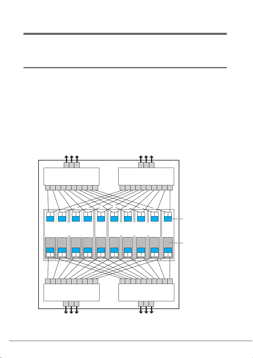
次の図に、シャーシに、6 台の BX620 S2 サーバブレード(スロット 5 ~ 10 占有)と、2
台の BX660 サーバブレード(スロット 1 ~ 4 占有)を搭載した構成例を示します。
本例では、各 LAN ドータカードからネットワークブレード間の LAN 接続を説明するた
め、すべてのサーバブレードに LAN ドータカードを搭載していますが、必ずしもすべて
のサーバブレードに LAN ドータカードを搭載する必要はありません。
11 12 13
PRIMERGY BX600
スイッチブレード(NET 1)
12345678910
1 2 3 4 5 6 7 8 9 10
c d
b
a
PRIMERGY BX660
サーバブレード
(スロット1〜4まで計2台)
C D
A B
12345678910
PRIMERGY BX600
スイッチブレード(NET 3)
11 12 13 11 12 13
LANドータカードは、ネットワークブレードスロット3または4
(NET3または4)に接続されます。
a
A B
c d
b
a b a b a b a b a b a b
C D
AB AB AB AB AB AB
PRIMERGY BX600
スイッチブレード(NET 2)
PRIMERGY BX620 S2
(スロット5〜10まで計6台)
PRIMERGY BX600
スイッチブレード(NET 4)
11 12 13
12345678910
サーバブレード
12345678910
オンボードLAN
LANドータカー
8
Page 9

` 同一シャーシ内に、LAN ドータカードを搭載したサーバブレードとファイバーチャ
ネルドータカードを搭載したサーバブレードの混載はできません。
` ネットワークブレードスロット 3 または 4(NET3 または 4)にスイッチブレードを搭
載する場合、ファイバーチャネルパススルーブレードの同時搭載はできません。
1.2 仕様
項目 仕様
型名
ホストバス仕様インタフェース PCI-X バス Rev.1.0a、PCI バス Rev. 2.3(論理仕様互換)
データ転送速度 最大 1GB/ 秒(PCI-X バス 133MHz 動作時)
データ転送方式 バスマスタ、DMA
外部インタフェース 1000BASE-T Ethernet (SerDes)インタフェース
(シャーシ内部接続の転送速度は最大 1Gbps 固定)
コントローラ LSI Intel
適用機種 BX600 サーバブレード
注) サーバブレードのドータカードスロットの PCI-X バス動作スピードにより異なります。
たとえば、PCI-X バスの動作周波数が 100MHz の場合、LAN ドータカードのデータ転送速度は、最大
800MB /秒(ピーク時)となります。
PG-LND101
64 ビット/ 133MHz
®
82546GB、デュアルポート
BX660 サーバブレード
BX620 S2 サーバブレード
[注]
1 LAN ドータカードについて 9
J
Page 10

2
警告
注意
LAN ドータカードの取り付け
この章では、サーバブレードへの搭載方法について説明します。
・ 取り付けや取り外しを行うときは、サーバブレードをシャーシから取り外して
ください。感電の原因となります。
シャーシからの取り外し方法は、『ハードウェアガイド シャーシ編』 を参照して
ください。
・ 内蔵オプションは、基板や半田づけした部分がむきだしになっています。これ
らの部分は、人体に発生する静電気によって損傷を受ける場合があります。
取り扱う前に、サーバ本体の金属部分に触れて人体の静電気を放電してくださ
い。
・ 基板表面や半田づけの部分に触れないように、金具の部分や基板の縁を持つよ
うにしてください。
・ 拡張カードは静電気の影響を受けやすいので、伝導パッドなどの上に置くか、
取り扱う直前まで梱包袋に入れておいてください。
2.1 BX600 / BX620 S2 サーバブレードへの搭載
10
` BX600 サーバブレードにLAN ドータカードを搭載する場合、事前にBIOS アップデー
トが必要となる場合があります。BIOS バージョンが「3B17」以降になっているこ
とを確認してください。「3B12」以前のバージョンの場合は、添付のアップデート
ツール、または最新のアップデートツールを富士通パソコン情報サイト
FMWORLD.NET の PRIMERGY 向けホームページ(http://www.fmworld.net/biz/
primergy/)から入手し、BIOS アップデートを実行してください。
` シャーシに搭載されたマネジメントブレードのバージョンが「1.41」以降の場合、
サーバブレードの BMC ファームウェアのアップデートも必要になる場合がありま
す。詳細については、各アップデートツールに添付のマニュアルを参照してくださ
い。
` LAN ドータカードを外部 LAN(装置)に接続するには、シャーシのネットワークブレード
スロット 3 または 4(NET3 または 4)にスイッチブレードまたは LAN パススルーブレー
ドを搭載する必要があります。
Page 11
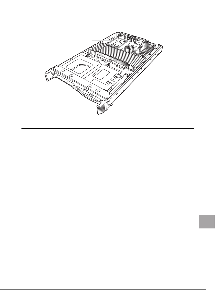
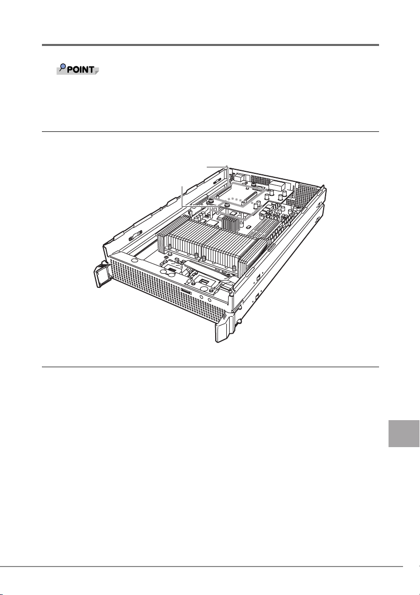
2.1.1 LAN ドータカードの取り付け位置
ド
BX600 / BX620 S2 サーバブレードのドータカードスロットに取り付けます。
ドータカードスロット
BX600/BX620 S2サーバブレー
2.1.2 LAN ドータカードの取り付け手順
1 LAN ドータカードを取り付けるサーバブレードの電源を切ります。
→ 『ハードウェアガイド シャーシ編 3.3 電源を切る』
2 シャーシの金属部分に触れて人体の静電気を放電します。
3 サーバブレードを、シャーシから取り外します。
→ 『ハードウェアガイド シャーシ編 4.2 サーバブレードの取り付け/取り外し』
4 トップカバーを取り外します。
BX600 サーバブレードの場合
→『BX600 サーバブレード ユーザーズガイド 8.2 トップカバーの取り付け/取り外
し』
BX620 S2 サーバブレードの場合
→『BX620 S2 サーバブレード ユーザーズガイド 7.2 トップカバーの取り付け/取
り外し』
2 LAN ドータカードの取り付け 11
J
Page 12
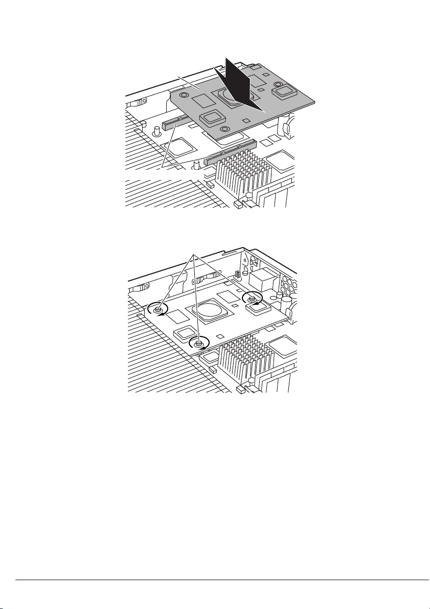
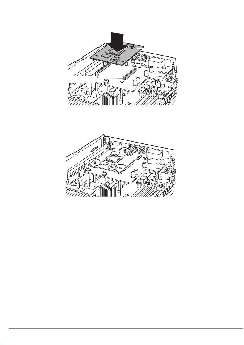
5 LAN ドータカードを取り付けます。
LAN ドータカードが完全にスロットに差し込まれたことを確認してください。
LANドータカード
ドータカードスロット
6 LAN ドータカードをネジで固定します。
LAN ドータカードを、カードに添付のネジ(3 本)で固定します。
ネジ
12
7 トップカバーを取り付けます。
BX600 サーバブレードの場合
→『BX600 サーバブレード ユーザーズガイド 8.2 トップカバーの取り付け/取り外
し』
BX620 S2 サーバブレードの場合
→『BX620 S2 サーバブレード ユーザーズガイド 7.2 トップカバーの取り付け/取
り外し』
8 サーバブレードをシャーシに取り付けます。
→ 『ハードウェアガイド シャーシ編 4.2 サーバブレードの取り付け/取り外し』
Page 13
2.2 BX660 サーバブレードへの搭載
` LAN ドータカードを外部 LAN(装置)に接続するには、シャーシのネットワークブレード
スロット 3 または 4(NET3 または 4)にスイッチブレードまたは LAN パススルーブレー
ドを搭載する必要があります。
2.2.1 LAN ドータカードの取り付け位置/搭載順について
BX660 サーバブレードのドータカードスロットに取り付けます。
LAN ドータカードは、ドータカードスロット 1、2 の順に搭載してください。
䊄䊷䉺䉦䊷䊄䉴䊨䉾䊃㪈
䊄䊷䉺䉦䊷䊄䉴䊨䉾䊃㪉
2.2.2 LAN ドータカードの取り付け手順
■ LAN ドータカードを 1 枚搭載する方法
1
LAN ドータカードを取り付けるサーバブレードの電源を切ります。
→『ハードウェアガイド シャーシ編 3.3 電源を切る』
2 シャーシの金属部分に触れて人体の静電気を放電します。
3 サーバブレードを、シャーシから取り外します。
→『ハードウェアガイド シャーシ編 4.2 サーバブレードの取り付け/取り外し』
4 ハードディスクを取り外してから、トップカバーを取り外します。
→『BX660 サーバブレード ユーザーズガイド 7.2 トップカバーの取り付け/取り外
し』
2 LAN ドータカードの取り付け 13
J
Page 14
5 LAN ドータカードをドータカードスロット 1 に取り付けます。
䊄
LAN ドータカードが完全にスロットに差し込まれたことを確認してください。
㪣㪘㪥䊄䊷䉺䉦䊷
䊄䊷䉺䉦䊷䊄䉴䊨䉾䊃㪈
ᒛ䊔䊷䉴䊗䊷䊄
6 LAN ドータカードをネジで固定します。
LAN ドータカードをカードに添付のネジ(3 本)で固定します。
14
7 トップカバーを取り付けます。
→ 『BX660 サーバブレード ユーザーズガイド 7.2 トップカバーの取り付け/取り
外し』
8 サーバブレードをシャーシに取り付けます。
→『ハードウェアガイド シャーシ編 4.2 サーバブレードの取り付け/取り外し』
Page 15

■ LAN ドータカードを 2 枚搭載する方法
1
LAN ドータカードを取り付けるサーバブレードの電源を切ります。
→『ハードウェアガイド シャーシ編 3.3 電源を切る』
` BX660 サーバブレードに、LAN ドータカードを 2 枚搭載している場合、サーバブ
レードの電源を切っても、オンボード LAN 用の LAN リンク LED が点灯(緑)
することがあります。サーバブレードが電源が切れた状態で、LAN リンク LED
が点灯していても無視してください。
2 シャーシの金属部分に触れて人体の静電気を放電します。
3 サーバブレードを、シャーシから取り外します。
→『ハードウェアガイド シャーシ編 4.2 サーバブレードの取り付け/取り外し』
4 ハードディスクを取り外してから、トップカバーを取り外します。
→『BX660 サーバブレード ユーザーズガイド 7.2 トップカバーの取り付け/取り外
し』
5 拡張ベースボードを取り外します。
すでにスロット 1 に LAN ドータカードが搭載されている場合は、「■ LAN ドータ
カードを 1 枚搭載する方法」(→ P. 1 3 )の手順 5 ~ 6 の逆の手順でスロット 1 の
カードを取り外してから拡張ベースボードを取り外してください。
䈧䉁䉂䊈䉳
ᒛ䊔䊷䉴䊗䊷䊄
2 LAN ドータカードの取り付け 15
J
Page 16
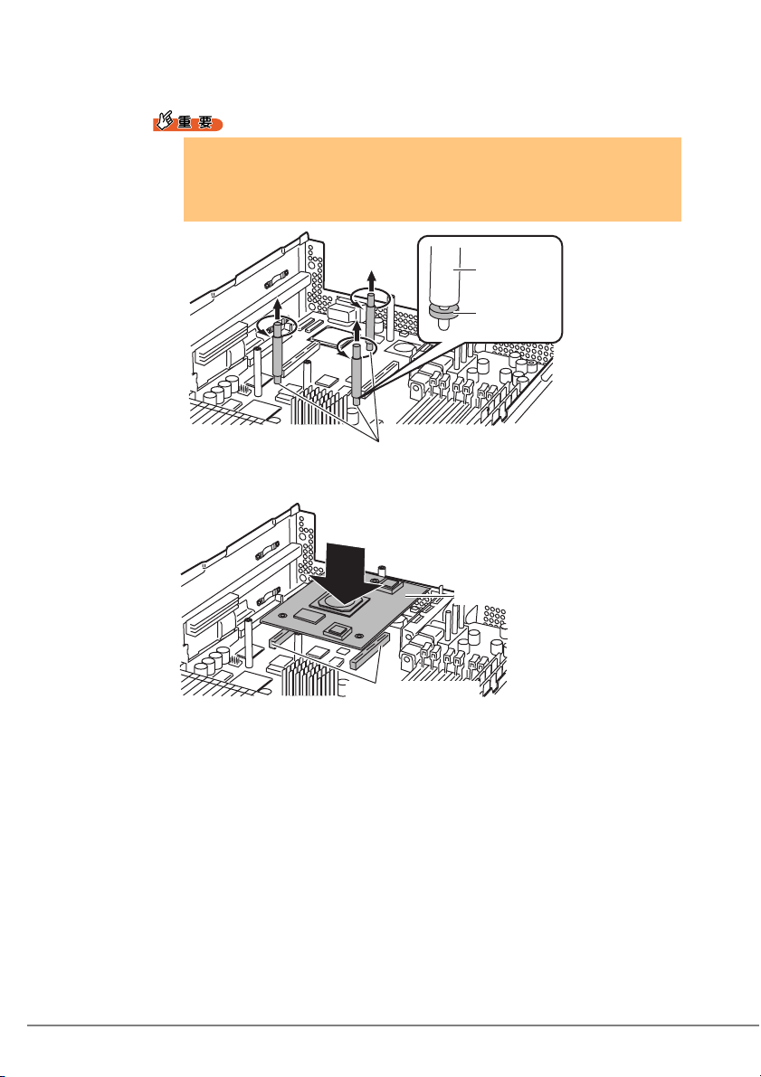
6 ドータカードスロット 2 のドータカード固定用ネジとスペーサを取り外
します。
` 各固定用ネジの下部にあるスペーサ(ワッシャー)は、ドータカードス
ロット 2 にドータカードを取り付ける場合には不要です。なお、ドータ
カードを取り外す場合には、同スペーサの再取り付けが必要になりますの
で、大切に保管してください。
࿕ቯ↪䊈䉳
䉴䊕䊷䉰
䋨䊪䉾䉲䊞䍎䋩
࿕ቯ↪䊈䉳
7 LAN ドータカードをドータカードスロット 2 に取り付けます。
16
㪣㪘㪥䊄䊷䉺䉦䊷䊄
䊄䊷䉺䉦䊷䊄䉴䊨䉾䊃㪉
Page 17

8 ドータカードスロット 2 に取り付けた LAN ドータカードを、手順 6 で取
り外したネジで固定します。
スペーサの再取り付けは、必要ありません。
9 手順 5 で取り外した拡張ベースボードを取り付けます。
10 LAN ドータカードをドータカードスロット 1 に取り付けます。
「■ LAN ドータカードを 1 枚搭載する方法」(→ P. 1 3 )の手順 5 ~ 6 を参照して取
り付けてください。
11 トップカバーを取り付けます。
→『BX660 サーバブレード ユーザーズガイド 7.2 トップカバーの取り付け/取り外
し』
12 サーバブレードを、シャーシに取り付けます。
→『ハードウェアガイド シャーシ編 4.2 サーバブレードの取り付け/取り外し』
2 LAN ドータカードの取り付け 17
J
Page 18
3
LAN ドライバのインストール
この章では、LAN ドライバのインストール方法について説明します。
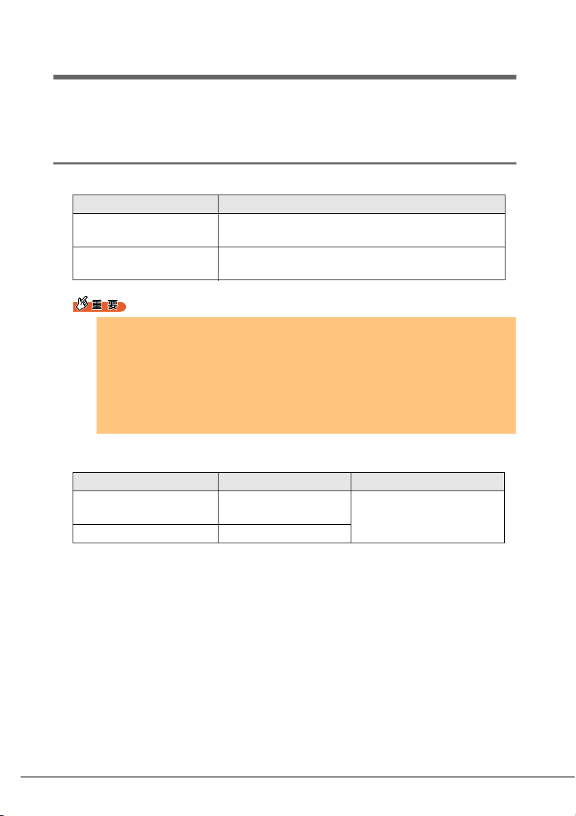
3.1 モジュールのバージョンレベル
本製品は、次の LAN ドライバで動作します。
OS の種類 LAN ドライバのバージョン
Windows Server 2003
Windows 2000 Server
Windows Server 2003 x64
` LAN ドライバは、次のいずれかから入手してインストールしてください。
・サーバブレード添付の ServerStart CD-ROM 内の LAN ドライバ
・富士通パソコン情報サイト FMWORLD.NET の PRIMERGY 向けホームページ
(http://www.fmworld.net/biz/primergy/)に公開されている LAN ドライバ
なお、上記より新しい LAN ドライバを使用する場合は、そのドライバに添付の取扱
説明書またはヘルプファイルを参照してください。
` インテル社のオンラインサービスからダウンロードした LAN ドライバは、
PRIMERGY サーバ上では使用しないでください。
LAN ドライバに含まれるモジュールのバージョンレベルは、次のとおりです。
『PG-185x/186x/187x/188x/189x/PG-LND101 LAN ドライ
バ V9.1』
『PG-185x/186x/187x/188x/189x/PG-LND101 LAN Driver &
Intel(R) PROSet LAN ドライバ V9.2』以降
18
OS の種類 モジュールバージョン カードの種類
Windows Server 2003
Windows 2000 Server
Windows Server 2003 x64 8.4.21.0
8.1.8.0
Gigabit Ethernet
(1000BASE-T/1000BASE-SX)
Page 19

3.1.1 バージョンレベルの確認方法
バージョンレベルの確認方法は次のとおりです。
OS の種類 確認方法
Windows Server 2003
Windows Server 2003 x64
Windows 2000 Server
®
・ Intel
・「デバイスマネージャ」で表示される LAN アダプタの名
・ Intel
・「デバイスマネージャ」で表示される LAN アダプタの名
・ Intel
・「デバイスマネージャ」で表示される LAN アダプタの名
PROSet の「ネットワークドライバ」のドライバ情
報の e1000325.sys のバージョン
称を右クリック後、「プロパティ」→「ドライバ」→「ド
ライバの詳細」で表示される e1000325.sys のバージョン
®
PROSet の「ネットワークドライバ」のドライバ情
報の e1G5132e.sys のバージョン
称を右クリック後、「プロパティ」→「ドライバ」→「ド
ライバの詳細」で表示される e1G5132e.sys のバージョン
®
PROSet の「ネットワークドライバ」のドライバ情
報の e1000nt5.sys のバージョン
称を右クリック後、「プロパティ」→「ドライバ」→「ド
ライバの詳細」で表示される e1000nt5.sys のバージョン
3.2 LAN ドライバについて
Windows 対応 LAN ドライバについて説明します。
3.2.1 ドライバのインストール
ドライバのインストールは、OS インストール時にネットワークアダプタが認識されてい
る場合と、されていない場合とで操作が異なります。
1 管理者権限でログオンします。
2 「スタート」ボタン→「管理ツール」→「コンピュータの管理」の順にク
リックします。
「コンピュータの管理」が表示されます。
3 LAN ドライバのインストール 19
J
Page 20

3 [デバイスマネージャ]をクリックします。
デバイスマネージャの一覧で、認識されているネットワークアダプタが存在するか
を確認します。
⼂䈘䉏䈩䈇䈭䈇
䊈䉾䊃䊪䊷䉪䉝䉻䊒䉺
⼂䈘䉏䈩䈇䉎
䊈䉾䊃䊪䊷䉪䉝䉻䊒䉺
認識されているネットワークアダプタが存在する場合は、「ネットワークアダプタ」
が表示されます。
・ 認識されているネットワークアダプタが存在する場合
最初に「ネットワークアダプタ」配下の LAN デバイス名に対して「3.2.2 LAN ド
ライバの更新」(→ P. 2 1 )を行ったあと、「その他のデバイス」配下の「イーサ
ネットコントローラ」に対して「3.2.3 LAN ドライバのインストール」(→ P. 2 3 )
を行ってください。
20
` OS インストール直後に認識されたネットワークアダプタのドライバの更新を行
う前に、「その他のデバイス」に対して LAN ドライバをインストールした場合
Page 21

ドライバのインストールが開始されたあと、次の画面が表示されます。
[完了]をクリックすると、「ヘルプとサポートセンター」の画面が表示されま
すが、[×]を クリックして画面を閉じてください。インストール後、デバイ
スマネージャの LAN デバイス名に「!」マークが表示されますが、 すべての
LAN ドライバインストール後、再起動すると正常に表示されます。
` 認識されているネットワークアダプタが存在しない場合
「その他のデバイス」配下の「イーサネットコントローラ」に対して、「3.2.3
LAN ドライバのインストール」(→ P. 2 3 )を行ってください。
3.2.2 LAN ドライバの更新
[デバイスマネージャ]の[ネットワークアダプタ]配下のすべての LAN デバイス名に対
して、 次の手順に従って行います。
■ Windows Server 2003 / Windows 2000 Server の場合
1
「ネットワークアダプタ」配下の LAN デバイス名をダブルクリックしま
す。
` LAN デバイス名は、次のように表示されます。
LAN カード LAN デバイス名
PG-LND101 Intel(R) PRO/1000 MB Dual Port Server Connection
` AFT などが作成済みの場合、次の仮想アダプタが存在しますが、選択しな
いでください。
・Intel(R) Advanced Network Service Virtual Adapter
2 LAN ドライバの CD またはフロッピーディスクをセットします。
ダウンロードした LAN ドライバの格納したフォルダを確認しておいてください。
3 LAN ドライバのインストール 21
J
Page 22
3 LAN デバイスのアイコンをダブルクリックします。
プロパティが表示されます。
4 [ドライバ]タブをクリックし、[ドライバの更新]をクリックします。
「ハードウェアの更新ウィザード」画面が表示されます。
5 「ソフトウェアを自動的にインストールする」を選択し、[次へ]をクリッ
クします。
ドライバのインストールが開始されます。
6 [完了]をクリックします。
7 [閉じる]をクリックします。
■ Windows Server 2003 x64 の場合
1
「ネットワークアダプタ」配下の LAN デバイス名をダブルクリックしま
す。
` LAN デバイス名は、次のように表示されます。
LAN カード LAN デバイス名
PG-LND101 Intel(R) PRO/1000 MB Dual Port Server Connection
` AFT などが作成済みの場合、次の仮想アダプタが存在しますが、選択しな
いでください。
・Intel(R) Advanced Network Service Virtual Adapter
22
2 LAN ドライバの CD またはフロッピーディスクをセットします。
ダウンロードした LAN ドライバの格納したフォルダを確認しておいてください。
3 LAN デバイスのアイコンをダブルクリックします。
プロパティが表示されます。
4 [ドライバ]タブをクリックし、[ドライバの更新]をクリックします。
「ハードウェアの更新ウィザード」画面が表示されます。
5 「一覧または特定の場所からインストールする」を選択し、[次へ]をク
リッ クします。
6 「検索しないで、インストールするドライバを選択する」を選択し、[次
へ] をクリックします。
7 [ディスク使用]をクリックします。
Page 23

8 「製造元のファイルのコピー元」を LAN ドライバの格納されている場所
に指定し、[OK]をク リックします。
9 「Intel(R) PRO/1000 MB Dual Port Server Connection」が表示された
ら、[次へ]をクリックします。
ドライバのインストールが開始されます。
10 [完了]をクリックします。
11 [閉じる]をクリックします。
ドライバの更新を行ったすべての LAN アダプタに対して正しく更新されていることを、
「3.1 モジュールのバージョンレベル」(→ P. 1 8)を参照して、バージョンが正しいことを
確認してください。
` LAN アダプタのプロパティで「受信記述子」の値を小さく設定しないでください。
3.2.3 LAN ドライバのインストール
[デバイスマネージャ]の[その他のデバイス]配下のすべての「イーサネットコント
ローラ」 に対して、次の手順に従って LAN ドライバのインストールを行ってください。
■ Windows Server 2003 の場合
1
LAN ドライバの CD またはフロッピーディスクをセットします。
ダウンロードした LAN ドライバの格納したフォルダを確認しておいてください。
2 「その他のデバイス」配下の「イーサネットコントローラ」をダブルク
リックします。
「イーサネットコントローラのプロパティ」画面が表示されます。
3 [全般]タブをクリックし、[ドライバの再インストール]をクリックしま
す。
「デバイスドライバのアップグレードウィザード」画面が表示されます。
4 「ソフトウェアを自動的にインストールする(推奨)」を選択し、[次へ]
をクリックします。
ドライバのインストールが開始されます。
5 [完了]をクリックします。
6 [閉じる]をクリックします。
プロパティ画面が終了します。
7 LAN ドライバの CD またはフロッピーディスクを取り出し、サーバブ
レードを再起動します。
3 LAN ドライバのインストール 23
J
Page 24

■ Windows Server 2003 x64 の場合
1
LAN ドライバの CD またはフロッピーディスクをセットします。
ダウンロードした LAN ドライバの格納したフォルダを確認しておいてください。
2 「その他のデバイス」配下の「イーサネットコントローラ」をダブルク
リックします。
「イーサネットコントローラのプロパティ」画面が表示されます。
3 [ドライバ]タブをクリックし、[ドライバの更新]をクリックします。
「ハードウェアの更新ウィザードの開始」画面が表示されます。
4 「一覧または特定の場所からインストールする」を選択し、[次へ]をク
リックします。
5 「検索しないで、インストールするドライバを選択する」を選択し、[次
へ] をクリックします。
6 [ディスク使用]をクリックします。
7 「製造元のファイルのコピー元」を LAN ドライバの格納されている場所
に指定し、[OK]をク リックします。
8 「Intel(R) PRO/1000 MB Dual Port Server Connection」が表示された
ら、[次へ]をクリックします。
ドライバのインストールが開始されます。
9 [完了]をクリックします。
10 [閉じる]をクリックします。
プロパティ画面が終了します。
11 LAN ドライバの CD またはフロッピーディスクを取り出し、サーバブ
レードを再起動します。
■ Windows 2000 Server の場合
1
LAN ドライバの CD またはフロッピーディスクをセットします。
ダウンロードした LAN ドライバは、格納したフォルダを確認しておいてください。
2 「その他のデバイス」配下の「イーサネットコントローラ」をダブルク
リックします。
「イーサネットコントローラのプロパティ」画面が表示されます。
3 [全般]タブをクリックし、[ドライバの再インストール]をクリックしま
す。
「デバイスドライバのアップグレードウィザード」画面が表示されます。
24
Page 25

4 [次へ]をクリックします。
5 「デバイスに最適なドライバをインストールする(推奨)」を選択し、[次
へ]をクリックします。
ドライバファイルの特定画面が表示されます。
6 検索場所のオプションに「CD-ROM ドライブ」または「フロッピーディ
スクドライブ」などを選択し、[次へ]をクリックします。
検出されたドライバが表示されます。
7 [次へ]をクリックします。
ドライバのインストールが開始され、終了すると完了画面が表示されます。
8 [完了]をクリックします。
9 [閉じる]をクリックします。
10 LAN ドライバの CD またはフロッピーディスクを取り出し、サーバブ
レードを再起動します。
ドライバのインストールを行ったすべての LAN アダプタに対して、正しく更新されてい
ることを、 「3.1 モジュールのバージョンレベル」(→ P. 1 8 )を参照して、バージョンが正
しいか確認して ください。
` LAN デバイス名は、次のように表示されます。
LAN カード LAN デバイス名
PG-LND101 Intel(R) PRO/1000 MB Dual Port Server Connection
` LAN アダプタのプロパティで「受信記述子」の値を小さく設定しないでください。
3.2.4 ドライバの削除
ドライバを削除する場合は、次の手順で行います。
1 管理者権限でログオンします。
2 Intel
3 「スタート」ボタン→「設定」→「コントロールパネル」→「アプリケー
®
PROSet を削除します。
→「4.4 アンインストール」(P. 2 8 )
ションの追加と削除」または「プログラムの追加と削除」の順にクリック
します。
3 LAN ドライバのインストール 25
J
Page 26

4 「Intel(R) PRO Network Connections Drivers」を選択し、「変更と削
除」をクリックします。
5 画面の指示に従い、削除します。
6 システムを再起動します。
26
Page 27

4
Intel® PROSet
この章では、Intel® PROSet について説明します。
®
` Intel
` インテル社のオンラインサービスからダウンロードした LAN ドライバは、
PROSet は、次のいずれかから入手してインストールしてください。
・サーバブレード添付の ServerStart CD-ROM 内の Intel
・富士通パソコン情報サイト FMWORLD.NET の PRIMERGY 向けホームページ
(http://www.fmworld.net/biz/primergy/)に公開されている Intel
・Windows Server 2003 / Windows 2000 Server の場合
PG-185x/186x/187x/188x/189x/PG-LND101 LAN ドライバ V9.1』の Intel
PROSet
・Windows Server 2003 x64 の場合
『PG-185x/186x/187x/188x/189x/PG-LND101 LAN Driver & Intel(R) PROSet LAN
ドライバ V9.2』以降の Intel
なお、上記より新しい Intel
取扱説明書またはヘルプファイルを参照してください。
PRIMERGY サーバ上では使用しないでください。
®
PROSet
®
PROSet を使用する場合は、そのドライバに添付の
®
PROSet
®
PROSet
®
4.1 Intel
Intel® PROSet を使用すると、LAN カード/ドライバの詳細な設定ができます。デュプ
レックスモード/チーム化/ VLAN の設定や LAN カードの診断を行う場合は、Intel
PROSet を使用してください。Intel
起動できます。
` OS がWindows の場合、LAN ドライバをインストールしただけではIntel® PROSet はインス
トールされません。
®
PROSet について
®
PROSet は、システムの「コントロールパネル」から
®
J
4 Intel® PROSet 27
Page 28

4.2 Windows Server 2003 / Windows 2000
Server システムでの注意事項
・ ServerStart を利用してドライバを自動インストールした場合は、Intel® PROSet も自動的
にインストールされます 。
®
PROSet が「コントロールパネル」に表示されていれば、インストール済みです。
・ Intel
本製品は、次の Intel
- Windows Server 2003 / Windows 2000 Server の場合
「V9.1(V9.1.0.0)」の Intel
- Windows Server 2003 x64 の場合
「V9.2」以降の Intel
®
Intel
PROSet を起動し、「Help」メニューの「About」をクリックし、インストールされ
ている Intel
り古い場合は、いったん Intel
ンをインストールしてください。
・ 設定情報の詳細については、Intel
®
®
PROSet でサポートされます。
®
PROSet
®
PROSet
PROSet のバージョンを確認します。Intel® PROSet のバージョンが上記よ
®
PROSet をアンインストールしてから、新しいバージョ
®
PROSet の「Help」をクリックして、ご覧ください。
4.3 インストール
Intel® PROSet のインストールは、次の手順で行います。
1 管理者権限でログオンします。
2 Intel
®
PROSet を含む CD または富士通パソコン情報サイト
FMWORLD.NET からダウンロードした「ProSet.EXE」を実行します。
「Automatic execution - runs setup immediately」が表示されます。
3 [OK]をクリックします。
「InstallShield Wizard」が表示されます。
4 画面の指示に従って、インストールします。
「Setup Type」画面では「Typi ca l」を選択してください。
4.4 アンインストール
Intel® PROSet をアンインストールする場合は、次の手順で行います。
1 管理者権限でログオンします。
2 「スタート」ボタン→「設定」→「コントロールパネル」の順にクリック
します。
28
Page 29

` チームおよび VLAN がある場合は、アンインストールする前に Intel
PROSet でチームおよび VLAN をすべて削除してください。
→「5.3 チームの削除」(P. 3 4 )
→「6.3 VLAN の削除」(P. 3 9 )
3 「プログラムの追加と削除」または「アプリケーションの追加と削除」 を
クリックします。
4 「Intel(R) PROSet for wired Connections」を選択し、「削除」をク
リックします。
5 画面の指示に従って、アンインストールします。
4.5 LAN ドータカードのテスト
LAN ドータカードのテストは、次の手順で行います。
4.5.1 テスト方法
1 管理者権限でログオンします。
®
2 「スタート」ボタン→「設定」→「コントロールパネル」→「有線用イン
®
テル
PROSet」の順にクリックし、Intel® PROSet を起動します。
3 テストする LAN アダプタ(LAN ドータカード)を選択して、[診断]タ
ブをクリックします。
4 診断したい項目のタブを選択して「テスト実行」ボタンをクリックし、
LAN ドータカードのテストを行います。
4.5.2 エラー発生時の対処について
次の方法で対処してください。
・ LAN ドータカードが正しくサーバブレードのドータカードスロットに搭載されているか
を確認してください。
・ スイッチ、ケーブルの接続環境を確認してください。
・ 上記で問題がない場合は、担当保守員に連絡してください。
4 Intel® PROSet 29
J
Page 30

5
ト
ト
チーム化(AFT/ALB/SFT)
この章では、チーム化(AFT/ALB/SFT)について説明します。
ド
` BX600 サーバブレードにおいて、スイッチブレードを内蔵したシステム構成では、
ALB(アダプティブ ロード バランシング)機能は利用できません。
5.1 チーム化(AFT/ALB/SFT)について
■ AFT/ALB
AFT(アダプタ フォルト トレランス)とは、LAN カード(LAN アダプタ)を複数枚使用
して、サーバとスイッチ(ハブ)間の経路を二重化する技術です。使用中の経路(Primary
link)で、スイッチのポート、ケーブル、LAN カードに異常が発生した場合
にもう一方の経路(Secondary link)に処理を切り替え、通信を中断することなく続行しま
す。
なお、AFT の場合、チーム内のポートはすべて同一スイッチに接続されている必要があり
ます。また、スイッチのスパニングツリー機能は、非活性状態(無効)にする必要があり
ます。
ALB(アダプティブ ロード バランシング)とは、AFT の二重化機能に加え、PRIMERGY
サーバからの送信データを、2 枚の LAN カードに振り分け送受信性能を向上させる技術で
す(受信は、「詳細設定」の「受信ロードバランシング」を「無効」にすると Primery Link
だけで行われます)。
・ AFT/ALB の構成例
他のLAN装置へ
(*)
、自動的
30
PRIMERGY
スイッチ
LAN
LAN
Primary link
Secondary link
クライアン
クライアン
■ SFT
SFT(スイッチ フォルト トレランス)とは、LAN カードが別々のスイッチに接続された
構成での二重化機能です。スイッチ側のスパニングツリー機能が活性化され、スイッチが
二重化された構成で使用できます。LAN カードと、そのカードが接続されているスイッチ
との間に異常が発生したとき
イッチの間(次の図←、↓、→)のエラーは検出できません。そのようなエラーに対応す
るためには、スイッチのスパニングツリー機能を活性状態(有効)にする必要がありま
す。
(*)
、使用する経路を切り替えます。しかし、スイッチとス
Page 31

・ SFT の構成例
PRIMERGY
LAN
LAN
*)LAN カードとスイッチ間のリンク断と同様の異常しか検出できません。したがって、
スイッチが部分的に故障しただけで、カードが接続されているポートがリンクレベルで
正常な場合は、通常、経路の切り替えは発生しません。
Primary link
Secondary link
スイッチ1
■ 注意事項
チーム化を使用する場合の注意事項を次に示します。
詳細については、Intel
・ チーム化は、Windows(SP2 以降必須)でのみ使用できます。
・ チームを構成すると、OS 上に仮想アダプタ(例:Intel(R) Advanced Network Services
Virtual Adapter など)が作成されます。上位プロトコルは、チームを構成している個々
の物理アダプタではなく、この仮想アダプタにバインドされます。
・ 高速チーム機能は使用しないでください。
・ ALB 使用時は、Windows Load Balancing Service(WLBS)や NLB(Network Load
Balancing)を使用することはできません。
・ AFT/ALB のチームの構成 1 組に使用可能な LAN のポートは、最大 4 ポートです。
また、同一システムでは最大 2 組までのチームを構成することができます。なお、使用
できる LAN のポート数は、システムごとに制限がありますのでご注意ください。
・ SFT 1 組に使用可能な LAN のポートは、最大 2 ポートです。また、同一システムでは最
大 2 組までのチームを構成することができます。
・ チーム内の LAN カードは、同一ネットワーク(ブロードキャストドメイン)に存在す
る必要があります。また、IP アドレスは共有します。
・ チーム化使用時は、次の対象プロトコルに限り使用できます。
- AFT/SFT: IP、NetBEUI、IPX(NCP)、IPX(NetBIOS)
-ALB: IP、IPX(NCP)
®
PROSet の「Help」を参照してください。
5 チーム化(AFT/ALB/SFT) 31
J
Page 32

■ LAN ドータカード使用時のチーミングについて
本製品でチーミングを行う場合、使用する OS によって、使用するソフトウェアとチーミ
ング可能な組合せが異なります。次の表に従ってご使用ください。
・ BX600 / BX660 サーバブレードの場合
動作 OS
Windows
2 ポート目
1ポート目
オンボード LAN
LAN ドータカード
拡張カードスロット
オンボード
LAN
BACS/BASP BACS/BASP BACS/BASP
BACS/BASP Intel PROSet/
BACS/BASP Intel PROSet/
LAN カード
(BX600 のみ)
LCB
[注]
[注]
[注]
Linux v.3
オンボード LAN LCB
LAN ドータカード LCB
拡張カードスロット
LAN カード
(BX600 のみ)
Linux v.2.1
オンボード LAN
BASP
LAN ドータカード - - -
拡張カードスロット
---
LAN カード
(BX600 のみ)
[注]:LCB : Linux Channel Bonding
・ BX620 S2 サーバブレードの場合
動作 OS
Windows
2 ポート目
1ポート目
オンボード LAN
LAN ドータカード
拡張カードスロット
LAN カード
(BX600 のみ)
Linux v.3
オンボード LAN LCB
LAN ドータカード LCB
拡張カードスロット
LAN カード
(BX600 のみ)
[注]:LCB : Linux Channel Bonding
オンボード
LAN
Intel PROSet/
PROSet II
Intel PROSet/
PROSet II
Intel PROSet/
PROSet II
[注]
[注]
[注]
LCB
なお、LCB を使用してチーミングを行う場合は、最新のリリースノートを参照してくださ
い。
LAN
ドータカード
拡張カード
スロット
Intel PROSet/
PROSet II
PROSet II
Intel PROSet/
PROSet II
[注]
LCB
[注]
LCB
[注]
LCB
PROSet II
[注]
LCB
[注]
LCB
[注]
LCB
--
LAN
ドータカード
Intel PROSet/
PROSet II
Intel PROSet/
PROSet II
Intel PROSet/
PROSet II
[注]
LCB
[注]
LCB
[注]
LCB
拡張カード
スロット
Intel PROSet/
PROSet II
Intel PROSet/
PROSet II
Intel PROSet/
PROSet II
[注]
LCB
[注]
LCB
[注]
LCB
32
Page 33

5.2 チームの作成
チームを作成する場合は、次の手順で行います。
1 管理者権限でログオンします。
2 「スタート」ボタン→「設定」→「コントロールパネル」→「有線用イン
®
テル
PROSet」の順にクリックし、Intel® PROSet を起動します。
3 チームに組み込む LAN アダプタを選択し、右クリックします。
4 「チームに追加」 の「新規チームを作成」をクリックします。
「チーム化 ウィザード」 が表示されます。
5 作成したいチームのタイプを選択します。
・ AFT 使用時:「アダプタ フォルト トレランス」
・ ALB 使用時:「アダプティブ ロード バランシング」
・ SFT 使用時:「スイッチ フォルト トレランス」
他のチームのタイプを選択しないでください。
6 [次へ]をクリックします。
7 チームに組み込む LAN アダプタを選択し、[次へ]をクリックします。
8 [完了]をクリックします。
9 [OK]をクリックし、Intel
チーム化の設定が完了すると、仮想アダプタ「Intel(R) Advanced Network Services
Vir tua l Ada pter 」が表示されます。
上位プロトコルは、本仮想アダプタにバインドされます。
チームを編成する LAN カードには、バインドできません。
IP アドレスは、本仮想アダプタに対して設定します。
®
PROSet を終了します。
10 システムを再起動します。
5 チーム化(AFT/ALB/SFT) 33
J
Page 34

5.3 チームの削除
チームを削除する場合は、次の手順で行います。
1 管理者権限でログオンします。
2 「スタート」ボタン→「設定」→「コントロールパネル」→「有線用イン
®
テル
PROSet」の順にクリックし、Intel® PROSet を起動します。
3 削除するチームを選択します。
4 「チームの削除」をクリックします。
確認メッセージが表示されます。
5 [OK]をクリックします。
6 [OK]をクリックし、Intel
®
PROSet を終了します。
7 システムを再起動します。
` OS が Windows の場合、AFT / ALB / SFT のチームを作成すると、システムの「デバ
イス マネージャ」や「ネットワークとダイヤルアップ接続」または「ネットワーク
接続」に仮想アダプタ(Intel(R) Advanced Network Service Virtual Adapter)が作
成されますが、この仮想アダプタを、「デバイス マネージャ」や「ネットワークと
ダイヤルアップ接続」、「ネットワーク接続」から無効化や削除を行わないでくださ
い。この仮想アダプタを削除する場合は、必ず Intel
®
PROSet をご使用ください。
34
Page 35

5.4 イベントログ
AFT/ALB/SFT 使用時は、次のイベントログが発生します(ソース:i ANSMiniport)。
ID
種別 メッセージ
6
情報 プライマリ アダプタが初期化されました:(アダプタ名)
7
情報 アダプタが初期化されました:(アダプタ名)
8
情報 (チーム名):チームが初期化されました。
10
情報 現在のプライマリ アダプタが次のアダプタから切り替わります:
(アダプタ名)
11
警告 次のアダプタ リンクは接続されていません:(アダプタ名)
12
情報 セカンダリ アダプタが優先します:(アダプタ名)
13
警告 (アダプタ名) がチームで無効化されました。
14
情報 セカンダリ アダプタがチームに再び追加されました:(アダプタ名)
15
情報 次のアダプタのリンクが接続されています:(アダプタ名)
16
エラー (チーム名):最後のアダプタはリンクを失いました。ネットワーク
接続が失われました。
17
情報 (チーム名):アダプタはリンクを再確立しました。ネットワークの
接続が復元されました。
18
情報 次の優先プライマリ アダプタが検出されました:(アダプタ名)
19
情報 次の優先セカンダリ アダプタが検出されました:(アダプタ名)
20
情報 次の優先プライマリ アダプタが優先されます:(アダプタ名)
21
情報 次の優先セカンダリ アダプタが優先されます:(アダプタ名)
22
警告 プライマリ アダプタは次のブローブを検出できませんでした:(アダ
プタ名) 原因:チームが分割されている可能性があります。
35
警告 1 アダプタの欠落している(チーム名)を初期化しています。すべて
のアダプタが 存在し、機能していることを確認してください。
38
情報 チームから(アダプタ名)が削除されました。
42
警告 (アダプタ名)が正しく設定されていません。 アダプタは、リモート
管理機能を処理すると同時にネットワークチームであることはでき
ません。
■ 注意事項
・ チーム化が正しく動作を開始した場合でも、システム起動時に、ID = 6、7、8 のイベン
トログが格納されますが、問題ありませんので無視してください。
・ チームを構成すると、システム起動時にイベントビューアのシステムログに ID = 11 の
警告ログと ID = 15 などのイベントログが複数格納される場合がありますが、問題あり
ませんので無視してください。
5 チーム化(AFT/ALB/SFT) 35
J
Page 36

5.5 チームを構成する LAN ドータカードの異常検
出とカードの交換手順について
チームを構成している LAN ドータカードを交換する場合は、次の手順で行います。
1 サーバブレード内の LAN ドータカードを交換します。
2 サーバブレードを起動します。
3 管理者権限でログオンします。
4 起動されているアプリケーションがあれば、すべて終了させます。
5 「スタート」ボタン→「設定」→「コントロールパネル」→「有線用イン
®
テル
PROSet」の順にクリックし、Intel® PROSet を起動します。
6 交換した LAN アダプタを選択し、右クリックします。
7 「チームから削除」を選択します。
確認メッセージが表示されることがあります。[OK]をクリックし、続行してくだ
さい。
8 チームから削除し、チームの外に移動した LAN アダプタを再度選択し、
右クリックします。
9 「チームを追加」を選択し、交換した LAN アダプタを再度チームに組み
込みます。
10 [OK]をクリックし、Intel
®
PROSet を終了します。
11 システムを再起動します。
` チームを構成する LAN ドータカードを交換する場合、交換前のカードがプライマリ
に設定されていると、カード交換後も交換前のカードの MAC アドレスが交換後の
カードに引き継がれて使用されます。そのため、交換されたカードが、同一セグメ
ントで再度使用されると、MAC アドレスの重複が発生してしまいます。チームで
使用中の LAN カードを交換する場合は、上記の手順で LAN ドライバを再設定する
ことが必要です。
` 交換するドータカードを、交換前のカードとは別のドータカードスロットに搭載す
る場合(特に BX660 サーバブレードの場合)は、ドライバの削除と再インストー
ルが必要です。
36
Page 37

6
VLAN
この章では、VLAN について説明します。
6.1 VLAN について
仮想 LAN(VLAN)とは、LAN に接続される装置を、物理的な接続形態ではなく論理的に
グループ化したものです。VLAN は、装置が使用できるネットワークセグメントを特定す
ることができます。これにより、ネットワークの性能とセキュリィティの向上が図られま
す。
また、VLAN は、複数のユーザや装置を論理的にグル-プ化する機能があるため、建物間
のネットワーク管理を容易にすることができます。
通常 VLAN とは、スイッチ側の設定によるもので、装置は、1 つの LAN カードごとに 1
つの VLAN にしか属することができません。しかし、本ドライバでは 1 つの LAN カード
上に複数の VLAN を構成することが可能です。また、本ドライバは、IEEE802.1Q で定義
された VLAN をサポートしています。
PRIMERGY
スイッチ
(IEEE802.1Qサポート)
VLAN30VLAN20VLAN10
VLAN10、20、30
LAN
■ 留意事項
詳細については、Intel® PROSet の「Help」を参照してください。
・ VLAN は、OS が Windows(SP2 以降必須)の場合のみ使用できます。
・ Windows 上で VLAN を追加したり削除したりする場合は、必ず Intel
てください。
Windows の「デバイス マネージャ」や「ネットワークとダイヤルアップ接続」、「ネット
ワーク接続」から、VLAN の削除や追加を行わないでください。Intel
ないと、VLAN を正しく追加したり削除したりできません。また、一度 VLAN を削除し
たあとに再度 VLAN を追加する場合は、システムを再起動したあとに、VLAN を追加し
てください。
®
PROSet を使用し
®
PROSet を使用し
J
6 VLAN 37
Page 38

・ VLAN 上では IP 以外のプロトコルを使用しないでください。
富士通通信制御サービスで、LLC、LNDFC プロトコルをインストールすると、VLAN
とこれらのプロトコルは、無条件にバインド(接続)されてしまいます。したがって、
IP 以外のプロトコルが、VLAN と同時にインストールされたシステムでは、VLAN とそ
れらのプロトコルのバインドを解除してください。
・ 1 つの LAN ポートに設定可能な VLAN の個数は最大 10 個です。
・ Windows で NetBIOS over TCP/IP が有効な VLAN は、システム全体で最大 4 本にしてく
ださい。
6.2 VLAN の作成
VLAN を作成する場合は、次の手順で行います。
1 管理者権限でログオンします。
2 LAN カードを接続するスイッチ(BX600 サーバブレードでは、シャーシ
に内蔵するスイッチブレード)のポートを、VLAN のタグフレームを送受
信できるように設定します。
3 「スタート」ボタン→「設定」→「コントロールパネル」→「有線用イン
®
PROSet」の順にクリックし、Intel® PROSet を起動します。
テル
4 VLAN を設定する LAN アダプタを選択し、右クリックします。
チームを構成しているアダプタに、VLAN を設定することはできません。
5 「VLAN の追加」をクリックします。
6 「ID」 と「名前」を設定して、[OK]をクリックします。
「ID」は、スイッチ側の設定値と一致している必要があります。設定可能な範囲は、
1 ~ 4094 です。
「名前」は、スイッチ側の設定と一致している必要はありません。
確認メッセージが表示された場合は、「はい」を選択してください。
7 設定する VLAN ごとに、手順 4 ~ 6 を繰り返します。
8 [OK]をクリックし、Intel
VLAN の設定が完了すると、仮想アダプタ「Intel(R) Advanced Network Services
Virtual Adapter」が表示されます。
上位プロトコルは、本仮想アダプタにバインドされます。
チームを編成する LAN カードには、バインドできません。
IP アドレスは本仮想アダプタに設定します。
®
PROSet を終了します。
9 システムを再起動します。
38
Page 39

6.3 VLAN の削除
VLAN を削除する場合は、次の手順で行います。
1 管理者権限でログオンします。
2 「スタート」ボタン→「設定」→「コントロールパネル」→「有線用イン
®
テル
PROSet」の順にクリックし、Intel® PROSet を起動します。
3 削除する VLAN を選択し、クリックします。
4 「VLAN の削除」をクリックします。
確認メッセージが表示されます。
5 [OK]をクリックします。
最後の VLAN を削除する場合、その旨のメッセージが表示されるので、[OK]を
クリックしてください。
6 [OK]をクリックし、Intel
®
PROSet を終了します。
7 システムを再起動します。
6 VLAN 39
J
Page 40

付録
A
A.1 ローカルアドレスの設定
ローカルアドレスを設定する場合は、次の手順で行います。
1 管理者権限でログオンします。
2 「スタート」ボタン→「設定」→「コントロールパネル」→「有線用イン
3 設定する LAN アダプタを選択し、[詳細設定]タブをクリックします。
4 「ローカル管理されるアドレス」の値に設定するローカルアドレスを設定
5 [OK]をクリックし、Intel
6 システムを再起動します。
` グローバルアドレスに戻したい場合は、手順 4 で設定した値を削除してください。
®
テル
PROSet」の順にクリックし、Intel® PROSet を起動します。
します。
「02」で始まる 16 進数 12 桁を入力してください。
®
PROSet を終了します。
A.2 ジャンボフレームについて
Gigabit Ethernet では、ジャンボフレームが使用できます。ジャンボフレームを使用する際
は、ジャンボフレームネットワーク内の機器は、すべてジャンボフレーム対応装置で構成
し、ジャンボフレームを「有効」に設定してください。
1 管理者権限でログオンします。
2 「スタート」ボタン→「設定」→「コントロールパネル」→「有線用イン
®
テル
PROSet」の順にクリックし、Intel® PROSet を起動します。
40
3 設定する LAN アダプタを選択し、「詳細設定」タブをクリックします。
4 「ジャンボ フレーム」に使用する値に設定します。
5 [OK]をクリックし、Intel
6 システムを再起動します。
®
PROSet を終了します。
Page 41

A.3 その他の注意事項
・ LAN ドータカードの LAN ポートに対して、PXE ブート(ネットワークブート)はサ
ポートされません。
オンボードの LAN コントローラに対して、PXE ブートを実行してください。
・ LAN ドータカードの Wa ke On LA N 機能はサポートされません。
・ LAN ドータカードの MAC アドレスおよび IP アドレスは、マネジメントブレードでは
確認できません。
同情報は、Intel
い。
®
PROSet または OS 上のハードウェア管理プログラムにて確認してくださ
付録 A 41
J
Page 42

42
Page 43

Before Reading This Manual
Thank you for purchasing the PRIMERGY 1Gbit/s Ethernet I/O Module (hereinafter referred to as
this product or the card).
The card can be installed in the daughter card slot of the Fujitsu server blade to configure the Local
Area Network (LAN) system. This manual explains the 1Gbit/s Ethernet I/O Modules and the LAN
driver (for Windows). Read this manual carefully to handle the product correctly.
For details about the LAN driver, refer to manuals supplied with the server blade or the Fujitsu
PRIMERGY website:
(http://primergy.fujitsu.com)
November 2005
For Your Safety
This manual contains important information, required to operate this product safely.
Thoroughly review the information in this manual before using this product. Especially note the points under "Safety",
and only operate this product with a complete understanding of the material provided.
This manual should be kept in an easy-to-access location for quick reference when using this product.
High Safety
The Products are designed, developed and manufactured as contemplated for general use, including without limitation,
general office use, personal use, household use, and ordinary industrial use, but are not designed, developed and
manufactured as contemplated for use accompanying fatal risks or dangers that, unless extremely high safety is secured,
could lead directly to death, personal injury, severe physical damage, or other loss (hereinafter "High Safety Required
Use"), including without limitation, nuclear reaction control in nuclear facility, aircraft flight control, air traffic control,
mass transport control, medical life support system, missile launch control in weapon system. You shall not use this
Product without securing the sufficient safety required for the High Safety Required Use. If you wish to use this Product
for High Safety Required Use, please consult with our sales representatives in charge before such use.
43
E
Page 44

Remarks
Warning Descriptions
Various symbols are used throughout this manual. These are provided to emphasize important points
for your safety and that of others. The symbols and their meanings are as follows. Be sure to fully
understand these before reading this manual.
WARNING
CAUTION
The following symbols are used to indicate the type of warning or cautions being described.
Ignoring this symbol could be potentially lethal.
Ignoring this symbol may lead to injury and/or damage the device or hardware
options.
The triangle mark emphasizes the urgency of the WARNING and CAUTION.
Details are inside the triangle and above it.
A barred circle ( ) warns against certain actions (Do Not). These actions are
detailed inside the circle and above it.
A black circle indicates actions that must be taken.
These actions are detailed inside the black circle and above it.
Key Descriptions / Operations
Keys are described by their representative characters instead of their exact key face
appearance, as shown below.
E.g.: [Ctrl] key, [Enter] key, [→] key, etc.
The following indicate pressing several keys at once.
E.g.: [Ctrl] + [F3] key, [Shift] + [↑] key, etc.
Symbols
Symbols used in this manual have the following meanings.
Symbols Meaning
These sections explain prohibited actions and points to note when using this
device. Make sure to read these sections.
These sections explain information needed to operate the hardware and
software properly. Make sure to read these sections.
→ This mark indicates reference pages or manuals.
44
Page 45

Abbreviations
The following expressions and abbreviations are used throughout this manual.
Product names Expressions and abbreviations
Microsoft
Microsoft
Microsoft
Microsoft
tion
Microsoft
Microsoft
Red Hat
Red Hat
Red Hat
Red Hat
PRIMERGY BX620 S2 Server Blade
PRIMERGY BX600 S2 Blade Server System Unit Chassis
PRIMERGY Switchblade 10+3 x 10/100/1000TX layer2 Switch Blade
PRIMERGY FC Pass-Thru Blade FC Pass-Thru Blade
PG-185x/186x/187x/188x/189x/PG-LND101
LAN Driver
®
Windows Server™ 2003, Standard Edition
®
Windows Server™ 2003, Enterprise Edition
®
Windows Server™ 2003, Standard x64 Edition
®
Windows Server™ 2003, Enterprise x64 Edi-
®
Windows® 2000 Server
®
Windows® 2000 Advanced Server
®
Enterprise Linux® ES (v.3 for x86)
®
Enterprise Linux® AS (v.3 for x86)
®
Enterprise Linux® ES (v.2.1 for x86)
®
Enterprise Linux® AS (v.2.1 for x86)
Windows Server
2003
Windows Server
2003 x64
Windows 2000
Server
Linux v.3
Linux v.2.1
BX620 S2 Server
Blade
LAN driver or the driver
Windows
Linux
Server blade
45
E
Page 46
Safety
For your safety and that of others, follow the guidelines provided on the following pages concerning
the use of this product.
WARNING
• Do not tinker with the product. Doing so may cause fire or electric shock.
• Keep the product away from water. Failure to do so may cause fire or electric
shock.
• When there is lightning nearby, unplug all power cords and external connecting
cords from the product. Failure to do so may cause destruction of the devices
and fire.
CAUTION
• Since the product is delicate, avoid using or storing it under extreme conditions,
such as excessively high or low temperature, high humidity, or in direct sunlight.
Do not bend or damage the card or subject it to extreme shock. Doing so may
cause failure or fire.
• While not in use, store the card in the bag in which it was packaged to protect it
from static electricity.
Check the items supplied
46
Before using the product, check that no supplied or attached items are missing.
If any items are missing, contact an office listed in "Appendix B Contact Information" (
• 1Gbit/s Ethernet I/O Module (this product)
• User's Guide (this manual)
Intel and LANDesk are registered trademarks of Intel Corporation in the USA.
Microsoft, Windows, and Windows Server are trademarks or registered trademarks of Microsoft
Corporation in the USA and other countries.
Linux is a trademark or registered trademark of Linus Torvalds in the USA and other countries.Red Hat
and all Red Hat-based trademarks and logos are trademarks or registered trademarks of Red Hat, Inc.
in the United States and other countries.
Other product names used are trademarks or registered trademarks of their respective manufacturers.
Other products are copyrights of their respective manufacturers.
All Rights Reserved, Copyright© FUJITSU LIMITED 2005
Jpg.77).
Page 47

Contents
1 1Gbit/s Ethernet I/O Module . . . . . . . . . . . . . . . . . . . . . . . . . . 48
1.1 Overview . . . . . . . . . . . . . . . . . . . . . . . . . . . . . . . . . . . . . . . . . . . . . . 48
1.2 Specifications . . . . . . . . . . . . . . . . . . . . . . . . . . . . . . . . . . . . . . . . . . . 49
2 Installing a 1Gbit/s Ethernet I/O Module . . . . . . . . . . . . . . . . 50
2.1 Installing to BX620 S2 Server Blade . . . . . . . . . . . . . . . . . . . . . . . . . 51
3 Installing the LAN Driver . . . . . . . . . . . . . . . . . . . . . . . . . . . . . 53
3.1 Module Version Level . . . . . . . . . . . . . . . . . . . . . . . . . . . . . . . . . . . . 53
3.2 LAN Driver . . . . . . . . . . . . . . . . . . . . . . . . . . . . . . . . . . . . . . . . . . . . . 54
4 Intel® PROSet . . . . . . . . . . . . . . . . . . . . . . . . . . . . . . . . . . . . . 62
4.1 Intel® PROSet . . . . . . . . . . . . . . . . . . . . . . . . . . . . . . . . . . . . . . . . . . 62
4.2 Notes on Windows Server 2003/ Windows 2000 Server System . . . 63
4.3 Installing . . . . . . . . . . . . . . . . . . . . . . . . . . . . . . . . . . . . . . . . . . . . . . . 63
4.4 Uninstalling . . . . . . . . . . . . . . . . . . . . . . . . . . . . . . . . . . . . . . . . . . . . . 64
4.5 1Gbit/s Ethernet I/O Module Test . . . . . . . . . . . . . . . . . . . . . . . . . . . 64
5 Teaming(AFT/ALB/SFT) . . . . . . . . . . . . . . . . . . . . . . . . . . . . . . 65
5.1 Teaming(AFT/ALB/SFT) . . . . . . . . . . . . . . . . . . . . . . . . . . . . . . . . . . 65
5.2 Creating a Team . . . . . . . . . . . . . . . . . . . . . . . . . . . . . . . . . . . . . . . . . 68
5.3 Removing a Team . . . . . . . . . . . . . . . . . . . . . . . . . . . . . . . . . . . . . . . 69
5.4 Event Log . . . . . . . . . . . . . . . . . . . . . . . . . . . . . . . . . . . . . . . . . . . . . . 70
5.5 Detecting an Error in 1Gbit/s Ethernet I/O Modules Composing a Team
and Replacing a Defective Card . . . . . . . . . . . . . . . . . . . . . . . . . . . . 71
6 VLAN . . . . . . . . . . . . . . . . . . . . . . . . . . . . . . . . . . . . . . . . . . . . . 72
6.1 VLAN . . . . . . . . . . . . . . . . . . . . . . . . . . . . . . . . . . . . . . . . . . . . . . . . . 72
6.2 Creating VLAN . . . . . . . . . . . . . . . . . . . . . . . . . . . . . . . . . . . . . . . . . . 73
6.3 Removing VLAN . . . . . . . . . . . . . . . . . . . . . . . . . . . . . . . . . . . . . . . . 74
Appendix A . . . . . . . . . . . . . . . . . . . . . . . . . . . . . . . . . . . . . . . . 75
A.1 Setting Local Address . . . . . . . . . . . . . . . . . . . . . . . . . . . . . . . . . . . . 75
A.2 Jumbo Frame . . . . . . . . . . . . . . . . . . . . . . . . . . . . . . . . . . . . . . . . . . . 75
A.3 Other Notes . . . . . . . . . . . . . . . . . . . . . . . . . . . . . . . . . . . . . . . . . . . . 76
Appendix B Contact Information . . . . . . . . . . . . . . . . . . . . . . . 77
47
E
Page 48

1
1Gbit/s Ethernet I/O Module
This chapter explains the features and specifications of this product.
1.1 Overview
This product is an expansion LAN card exclusive to BX620 S2 Server Blade. This product has a
dual-port (2 ports) LAN controller, and provides LAN connection completely separate/ independent
of the onboard LAN. The external access is performed via the Switch Blade installed to the network
blade slot 3 or 4 (NET3 or NET4) on the chassis.
One product can be added to one BX620 S2 Server Blade. The following figure shows a
configuration example when ten BX620 S2 Server Blades (slot 1 to 10) are installed in the chassis. In
this example, 1Gbit/s Ethernet I/O Modules are installed in all server blades for convenience of
explaining LAN connection between each 1Gbit/s Ethernet I/O Module and network blade, however,
1Gbit/s Ethernet I/O Modules do not necessarily need to be installed on all server blades.
11 1213 11 12 13
PRIMERGY BX600
Switch Blade(NET 1)
12345678910
1
2
3 4 5 6 7 8 9 10
a b
c d
c d
a b
PRIMERGY BX620 S2 Server Blades
a b a b a b a b a b a b
PRIMERGY BX600
Switch Blade(NET 2)
12345678910
Onboard LAN
48
B
A
C D
12345678910
PRIMERGY BX600
Switch Blade(NET 3)
11 12 13 11 12 13
1Gbit/s Ethernet I/O Modules are connected to network blade slot3 or 4 (NET3 or 4)
A B
C D
AB AB AB AB AB AB
12345678910
PRIMERGY BX600
Switch Blade(NET 4)
1Gbit/s Ethernet
I/O Module
Page 49

` A server blade installed with a 1Gbit/s Ethernet I/O Module and a server blade
installed with a 2Gbit/s FC I/O Module cannot be installed to the same chassis.
` When a Switch Blade or a GbE Pass-Thru Blade is installed to network blade slot 3
or 4 (NET3 or 4), a FC Pass-Thru Blade cannot be installed at the same time.
1.2 Specifications
Item
Product ID PG-LND101
Host bus
specifications
External interface 1000BASE-T Ethernet (SerDes) interface (Maximum transfer speed
Controller LSI Intel(R) 82546GB, dual port
Applicable model BX620 S2 Server Blade
*1: It varies depending on the PCI-X bus operation speed of the server blade daughter card slot. For example,
when PCI-X bus clock frequency is 100MHz, the data transfer speed of the 1Gbit/s Ethernet I/O Module is
maximum 800MB/sec (at peak).
Interface PCI-X bus Rev.1.0a, PCI bus Rev.2.3 (Compatible with logical
Data transfer rate Max. 1GB/sec. (At PCI-X bus 133MHz operation) *1
Data transfer system Bus master, DMA
at the chassis internal connection is fixed to 1Gbps)
Specifications
specifications) 64 bit/133MHz
1 1Gbit/s Ethernet I/O Module 49
E
Page 50

2
Installing a 1Gbit/s Ethernet I/O Module
This chapter explains how to install a 1Gbit/s Ethernet I/O Module to the server
blade.
WARNING
• When installing or removing the 1Gbit/s Ethernet I/O Module, make sure to
remove the server blade from the chassis. Failure to do so may cause electric
shock. For details on how to remove the server blade from the chassis, refer to
"Hardware Guide (Chassis)".
CAUTION
• The circuit boards and soldered parts of internal options are exposed. They can
be damaged by static electricity. Before handling them, first touch a metal part of
the server to discharge static electricity from your body.
• Do not touch the circuitry on boards or soldered parts. Hold the metallic areas or
the edges of the circuit boards.
• Expansion cards are susceptible to static electricity. Place them on conductive
pads or keep them in their packaging as long as they are not necessary.
50
Page 51

2.1 Installing to BX620 S2 Server Blade
` To connect a 1Gbit/s Ethernet I/O Module to the external LAN (device), it is necessary to
install a Switch Blade or GbE Pass-Thru Blade to network blade slot 3 or 4 (NET3 or 4) of
the chassis.
2.1.1 Location of 1Gbit/s Ethernet I/O Module
Installation
Install the 1Gbit/s Ethernet I/O Module in the daughter card slot in the BX620 S2 Server Blade.
Daughter card slot
BX620 S2 Server Blade
2.1.2 Installing a 1Gbit/s Ethernet I/O Module
1 Turn off the server blade.
→ "3.3 Turning Off the Server " in "Hardware Guide (Chassis)"
2 Touch a metal part of the chassis to discharge static electricity
from your body.
3 Remove the server blade from the chassis.
→"Chapter 4.2 Installing Server Blade" in "Hardware Guide (Chassis)"
4 Remove the top cover.
→"7.2 Removing and Attaching the Top Cover" in "BX620 S2 Server Blade User's Guide"
2 Installing a 1Gbit/s Ethernet I/O Module 51
E
Page 52

5 Install the 1Gbit/s Ethernet I/O Module.
Check that the 1Gbit/s Ethernet I/O Module is securely inserted to the slot.
1Gbit/s Ethernet I/O Module
Daughter card slot
6 Secure the 1Gbit/s Ethernet I/O Module with the screws.
Fix the 1Gbit/s Ethernet I/O Module using the three screws supplied with the card.
Screws
52
7 Attach the top cover.
→"8.2 Removing and Attaching the Top Cover" in "BX620 S2 Server Blade User's Guide"
8 Install the server blade to the chassis.
→"4.2 Installing Server Blade" in "Hardware Guide (Chassis)"
Page 53

3
Installing the LAN Driver
This chapter explains how to install the LAN driver.
3.1 Module Version Level
This product runs on the following LAN driver.
OS type LAN driver version
Windows Server 2003
Windows 2000 Server
Windows Server 2003 x64 "PG-185x/186x/187x/188x/189x/PG-LND101 LAN Driver & Intel(R)
` Obtain and install a LAN driver from any of the following:
• The LAN driver in the ServerStart CD-ROM provided with the server blade
• The LAN driver available on the Fujitsu PRIMERGY website (http://
primergy.fujitsu.com)
When using a LAN driver with a newer version than that of the above, refer to the
user's guide or help file supplied with the driver.
` Do not use a LAN driver downloaded from the Intel online service on the PRIMERGY
server.
The versions of the module included in the LAN driver are as follows.
"PG-185x/186x/187x/188x/189x/PG-LND101 LAN driver V9.1"
PROSet LAN driver V9.2" or later
OS type
Windows Server 2003
Windows 2000 Server
Windows Server 2003 x64 8.4.21.0
Module
version
8.1.8.0
Card type
Gigabit Ethernet (1000BASE-T/1000BASE-SX)
E
3 Installing the LAN Driver 53
Page 54

3.1.1 How to check version level
How to confirm the version level is described below.
OS types Confirmation method
Windows Server 2003
Windows Server 2003 x64
Windows 2000 Server
• Intel(R) PROSet [Network Driver] driver information
e1000325.sys version
• Right-click the LAN adapter name displayed in [Device Man-
ager], and [Properties] → [Driver] → [Driver Details] displays
e1000325.sys version
• Intel(R) PROSet [Network Driver] driver information
e1G5132e.sys version
• Right-click the LAN adapter name displayed in [Device Man-
ager], and [Properties] → [Driver] → [Driver Details] displays
e1G5132e.sys version
• Intel(R) PROSet [Network Driver] driver information
e1000nt5.sys version
• Right-click the LAN adapter name displayed in [Device Man-
ager], and [Properties] → [Driver] → [Driver Details] displays
e1000nt5.sys version
3.2 LAN Driver
This section explains LAN drivers corresponding to Windows.
3.2.1 Installing the Driver
The driver installation procedure differs depending on whether the network adapter was recognized
during the OS installation.
54
1 Log on with administrator privileges.
2 Click [Start] → [Administrative Tools] → [Computer Management].
The [Computer Management] window appears.
Page 55

3 Click [Device Manager].
On the Device Manager list, check if a recognized network adapter is present.
Recognized network
adapters
Unrecognized network
adapters
When a recognized network adapter is present, [Network adapters] appears.
• When a recognized network adapter is present
Perform "3.2.2 Updating LAN Drivers" (
[Network adapters], then "3.2.3 Installing the LAN Driver" (
controller] under [Other devices].
` When the LAN driver is installed to [Other devices] before updating the driver for
the network adapter recognized immediately after the OS installation
When driver installation starts, the following window appears.
Jpg.56) on the LAN device name under
Jpg.58) on [Ethernet
Clicking [Finish] displays the [Help and Support Center] window. Click [X] to
close the window. After installation, the "!" mark is displayed at the LAN device
name in Device Manager. Device names are displayed properly when all LAN
drivers are installed and the system is restarted.
` When a recognized network adapter is not present
3 Installing the LAN Driver 55
E
Page 56

Perform "3.2.3 Installing the LAN Driver" (Jpg.58) on [Ethernet controller] under
[Other devices].
3.2.2 Updating LAN Drivers
Perform the following procedures on all LAN device names under [Network adapters] in [Device
Manager].
Windows Server 2003/Windows 2000 Server
Double-click a LAN device name under [Network adapters].
1
` The LAN device names are displayed as follows.
Ethernet controller LAN device name
PG-LND101 Intel(R) PRO/1000 MB Dual Port Server Connection
` When AFT is already created, the virtual adapter below exists. Do not
select it.
• Intel(R) Advanced Network Service Virtual Adapter
2 Insert a CD or floppy disk of the LAN driver.
Confirm the folder that contains the downloaded LAN driver in advance.
3 Double click the icon of the LAN device.
The properties are displayed.
4 Click the [Driver] tab and click [Update Driver].
The [Welcome to the Upgrade Device Driver Wizard] window appears.
5 Select [Install the software automatically] and click [Next].
The driver will be installed.
6 Click [Finish].
7 Click [Close].
Windows Server 2003 x64
Double-click a LAN device name under [Network adapters].
1
` The LAN device names are displayed as follows.
56
Ethernet controller LAN device name
PG-LND101 Intel(R) PRO/1000 MB Dual Port Server Connection
Page 57

` When AFT is already created, the virtual adapter below exists. Do not
select it.
• Intel(R) Advanced Network Service Virtual Adapter
2 Insert the LAN driver CD or floppy disk.
Confirm the folder that contains the downloaded LAN driver in advance.
3 Double-click the LAN device icon.
The properties are displayed.
4 Click the [Driver] tab and click [Update Driver].
The [Welcome to the Upgrade Device Driver Wizard] window appears.
5 Select [Install from a list or specific location] and click [Next].
6 Select [Don't search. I will choose the driver to be installed] and
click [Next].
7 Click [Use Disk].
8 Specify the [Copy manufacturer's files from...] in the location
where the LAN driver is stored and click [OK].
9 When [Intel(R) PRO/1000MB Dual Port Server Connection]
appears, click [Next].
The driver will be installed.
10 Click [Finish].
11 Click [Close].
Referring to "3.1 Module Version Level" (Jpg.53), check that the drivers updated for all LAN
adapters are correctly updated and that the version is correct.
` Do not specify a lower value in [Receiving descriptor] for the properties of the LAN
adapter.
3 Installing the LAN Driver 57
E
Page 58

3.2.3 Installing the LAN Driver
According to the procedures below, install the LAN driver for all the Ethernet controllers listed under
Other Devices of Device Manager.
Windows Server 2003
Insert a CD or floppy disk of the LAN driver.
1
Confirm the folder that contains the downloaded LAN driver in advance.
2 Double-click [Ethernet controller] under [Other devices].
The [Ethernet Controller Properties] window appears.
3 Click the [General] tab and click [Reinstall Driver].
The [Device Driver Upgrade Wizard] window appears.
4 Select [Install the software automatically (Recommended)] and
click [Next].
The driver will be installed.
5 Click [Finish].
6 Click [Close].
Properties window closes.
7 Eject the CD or the floppy disk of the LAN driver, and restart the
server blade.
Windows Server 2003 x64
Insert the LAN driver CD or floppy disk.
1
Confirm the folder that contains the downloaded LAN driver in advance.
2 Double-click [Ethernet controller] under [Other devices].
The [Ethernet Controller Properties] window appears.
3 Click the [Driver] tab and click [Update Driver].
The [Welcome to the Upgrade Device Driver Wizard] window appears.
4 Select [Install from a list or specific location] and click [Next].
5 Select [Don't search. I will choose the driver to be installed] and
click [Next].
6 Click [Have Disk].
7 Specify the [Copy manufacturer's files from] in the location where
the LAN driver is stored and click [OK].
58
Page 59

8 When [Intel(R) PRO/1000MB Dual Port Server Connection]
appears, click [Next].
The driver will be installed.
9 Click [Finish].
10 Click [Close] to exit the properties window.
Properties window closes.
11 Eject the ServerStart CD-ROM, and restart the server blade.
3 Installing the LAN Driver 59
E
Page 60

Windows 2000 Server
Insert a CD or floppy disk of the LAN driver.
1
Confirm the folder that contains the downloaded LAN driver in advance.
2 Double-click [Ethernet controller] under [Other devices].
The [Ethernet Controller Properties] window appears.
3 Click the [General] tab and click [Reinstall Driver].
The [Device Driver Upgrade Wizard] window appears.
4 Click [Next].
5 Select [Search for a suitable driver for my device (recommended)]
and click [Next].
The [Identify Driver File] window appears.
6 Select [CD-ROM drive] or [Floppy disk drive] in [Optional search
locations:] and click [Next].
Detected drivers are displayed.
7 Click [Next].
Driver installation starts. When it is completed, a completion window appears.
8 Click [Finish].
9 Click [Close].
60
10 Eject the CD or the floppy disk of the LAN driver, and restart the
server blade.
Referring to "3.1 Module Version Level" (Jpg.53), check that the drivers updated for all LAN adapters are correctly updated and that the version is correct.
` The LAN device names are displayed as follows.
LAN card LAN device name
PG-LND101 Intel(R) PRO/1000 MB Dual Port Server Connection
` Do not specify a lower value in [Receiving descriptor] for the properties of the LAN
adapter.
Page 61

3.2.4 Removing the Driver
Perform the following procedures to remove the driver.
1 Log on with administrator privileges.
2 Remove Intel
J"4.4 Uninstalling"(pg.64)
3 Click [Start] → [Settings] → [Control Panel] → [Add or Remove
Applications] or [Add or Remove Programs].
4 Select [Intel(R) PRO Network Connections Drivers] and click
[Change/Remove].
5 Follow the instruction on the window to remove the driver.
6 Restart the system.
®
PROSet.
3 Installing the LAN Driver 61
E
Page 62

4
Intel® PROSet
This chapter explains Intel® PROSet.
` Obtain and install Intel
• Intel(R)PROSet in the ServerStart CD-ROM provided with the server blade
• Intel(R)PROSet available on the Fujitsu PRIMERGY website (http://
primergy.fujitsu.com)
• For Windows Server 2003/ Windows 2000 Server
Intel(R)PROSet "PG-185x/186x/187x/188x/189x/PG-LND101 LAN driver V9.1"
• For Windows Server 2003 x64
Intel® PROSet "PG-185x/186x/187x/188x/189x/PG-LND101 LAN Driver & Intel®
PROSet LAN driver V9.2" or later
When using a newer version of Intel® PROSet than the above, refer to the user's
guide or help file supplied with the driver.
` Do not use Intel
PRIMERGY server.
4.1 Intel
Detailed settings of the Ethernet controller/the LAN driver are available using "Intel® PROSet". To
operate Duplex mode/ Teaming/ VLAN setting or Ethernet controller diagnosis, use "Intel
PROSet". "Intel
` For Windows OS, simply installing this driver does not install "Intel® PROSet".
®
PROSet
®
PROSet" can be started from [Control Panel] in the system.
®
PROSet from and of the following:
®
PROSet downloaded from the Intel online service on the
®
62
Page 63

4.2 Notes on Windows Server 2003/ Windows
2000 Server System
• When a driver is automatically installed using ServerStart, Intel® PROSet is also installed automatically.
®
•If Intel
• For details on the settings, click [Help] in Intel
PROSet is displayed in the [Control Panel], it is already installed.
This product is supported in the following Intel
- For Windows Server 2003/ Windows 2000 Server
®
Intel
PROSet "V9.1 (V9.1.0.0)"
- For Windows Server 2003 x64
®
PROSet "V9.2" or later
Intel
®
Start Intel
If the Intel
version.
PROSet, and click [Help] → [About] to confirm the installed Intel® PROSet version.
®
PROSet version is older than the above, uninstall the Intel® PROSet and install a new
®
PROSet:
®
PROSet.
4.3 Installing
Perform the following procedures to install Intel® PROSet.
1 Log on with the administrator privileges.
2 Execute "ProSet.EXE" in the CD containing Intel
downloaded from the Fujitsu PRIMERGY website.
[Automatic execution - runs setup immediately] appears.
®
PROSet or
3 Click [OK].
[InstallShield Wizard] appears.
4 Follow the instruction on the window for installation.
Select [Typical] in the [Setup Type] window.
E
4 Intel® PROSet 63
Page 64

4.4 Uninstalling
Perform the following procedures to uninstall Intel® PROSet.
1 Log on with the administrator privileges.
2 Click [Start] → [Settings] → [Control Panel].
` If team and VLAN are included, remove both of them using Intel
before uninstallation.
J"5.3 Removing a Team"(pg.69)
J"6.3 Removing VLAN"(pg.74)
3 Click [Add or Remove Programs] or [Add/Remove Applications].
4 Select [Intel(R) PROSet for wired Connections] and click
[Remove].
5 Follow the instruction on the window for uninstallation.
4.5 1Gbit/s Ethernet I/O Module Test
Perform the following procedures to test 1Gbit/s Ethernet I/O Module.
4.5.1 Test Method
1 Log on with administrator privileges.
2 Click [Start] → [Settings] → [Control Panel] → [Intel®PROSet
Wired], and start Intel
3 Select LAN adapter (1Gbit/s Ethernet I/O Module) to test and click
[Diagnostics] tab.
®
PROSet.
®
PROSet
4 Select a tab to diagnose, click [Run Test] to test the 1Gbit/s
Ethernet I/O Module.
4.5.2 Actions to Take When an Error Occurs
Follow the instructions below.
• Check that the 1Gbit/s Ethernet I/O Module is correctly installed to the server blade daughter card
slot.
• Check the connecting environment of switches and cables.
• If the error still occurs, contact an office listed in "Appendix B Contact Information" (
64
Jpg.77).
Page 65

5
Teaming(AFT/ALB/SFT)
This chapter explains Teaming (AFT/ALB/SFT).
` In a system configuration containing a Switch Blade in the BX600 Server Blade, the
Adaptive Load Balancing (ALB) function is not available.
5.1 Teaming(AFT/ALB/SFT)
AFT/ALB
Adapter Fault Tolerance (AFT) is a technology of redundant paths between the server and switch
(hub) using multiple Ethernet controllers (LAN adapters). If an error occurs in a switch port, cable, or
LAN port when the path is in use (Primary link)(*), the process is automatically switched to another
path (Secondary link) so that the transmission can be continued without disruption.
For AFT, all ports in a team must be connected to the same switch. Also, the switch spanning tree
function is required not to be activated (disabled).
Adaptive Load Balancing (ALB) is, in addition to the AFT redundant function, a technology to
improve transmission performance to split data from PRIMERGY server to two Ethernet controllers
(Data reception is performed only with Primary Link if [Advanced] - [Receive Load Balancing] is set
to [Disabled]).
• Configuration example of AFT/ALB
To other LAN driver
PRIMERGY Server
Ethernet controller
Ethernet controller
Primary link
Secondary link
Switch
Client
Client
E
5 Teaming(AFT/ALB/SFT) 65
Page 66

SFT
Switch Fault Tolerance (SFT) is a redundant function with a configuration in which each LAN card is
connected to a different switch. Spanning tree function on the switch is enabled, so that the switch
can be used in the redundant configuration. When an error occurs (*) between the LAN card and its
connected switch, the path to use is switched. However, errors between switches (arrows in the
following figure) cannot be detected. For such errors, it is necessary that the switch spanning tree
function is activated (enabled).
PRIMERGY Server
Ethernet controller
Ethernet controller
Primary link
Secondary link
Switch1
* : Link disruption between the LAN card and switch, and equivalent errors are the only errors that
can be detected. Therefore, when a switch is partly faulty but the port connected to the card is
normal in the link level, usually the path will not be switched.
Note
The notes on using the teaming function are as follows:
For more details, refer to [Help] in Intel
• The teaming function is available only for Windows (SP2 or later required).
• Once a Team is created, a virtual adapter (example: Intel(R) Advanced Network Services Virtual
Adapter) is created on OS. Upper protocols are bound with the virtual adapter, not with each physical adapter composing the team.
• Do not use the high-speed teaming function.
• When ALB is being used, you cannot use Windows Load Balancing Service (WLBS) or Network
Load Balancing (NLB).
• Up to four LAN ports are available for each AFT/ALB team configuration.
• In the same system, a maximum of two teams can be configured. Note that the number of available
LAN ports is limited depending on each system.
• Up to two LAN ports are available for each SFT team configuration. In the same system, a maximum of two teams can be configured.
• Ethernet controllers in a team must be on the same network (broadcast domain). The IP address is
shared.
• Only the following protocols are available for the teaming function.
- AFT/SFT: IP, NetBEUI, IPX (NCP), IPX (NetBIOS)
- ALB: IP, IPX (NCP)
®
PROSet.
66
Page 67

Tea m i n g 1 G b i t/ s E t h e rn e t I/O Module during use
When teaming this product, the possible software and teaming combinations will vary depending on
the OS being used.
Adhere to the table below.
OS
Windows
Linux v.3 Onboard LAN LCB
* : LCB : Linux Channel Bonding
2nd Port
1st Port
Onboard LAN Intel PROSet/
PROSet II
1Gbit/s Ethernet I/O
Module
Expansion card slot
(BX600 only)
1Gbit/s Ethernet I/O
Module
Expansion card slot
(BX600 only)
Intel PROSet/
PROSet II
Intel PROSet/
PROSet II
LCB
LCB
Onboard LAN
(*)
(*)
(*)
1Gbit/s Ethernet
I/O Module
Intel PROSet/
PROSet II
Intel PROSet/
PROSet II
Intel PROSet/
PROSet II
LCB
LCB
LCB
When performing teaming using LCB, refer to the latest release note.
Expansion
card slot
Intel PROSet/
PROSet II
Intel PROSet/
PROSet II
Intel PROSet/
(*)
(*)
(*)
PROSet II
(*)
LCB
(*)
LCB
(*)
LCB
5 Teaming(AFT/ALB/SFT) 67
E
Page 68

5.2 Creating a Team
Perform the following procedures to create a team.
1 Log on with the administrator privileges.
2 Click [Start] → [Settings] → [Control Panel] → [Intel®PROSet
Wired], and start Intel
®
PROSet.
3 Select a LAN adapter to build in the team, and right click.
4 Click [Add to Team] → [Create New Team...].
The [Teaming wizard] window appears.
5 Select a Teaming type with which you want to create a Team.
• AFT type: "Adapter fault tolerance"
• ALB type: "Adaptive load balancing"
• SFT type: "Switch fault tolerance"
Do not select other types of team.
6 Click [Next].
7 Select LAN adapter to build in the team, and click [Next].
8 Click [Finish].
9 Click [OK] and exit Intel
When the teaming setting is completed, a virtual adapter "Intel(R) Advanced Network
Services Virtual Adapter" appears.
Upper layer protocol is bound to this virtual adapter.
You cannot bind them with the Ethernet controller that makes up a Team.
The IP address is set in this virtual adapter.
®
PROSet.
10 Restart the system.
68
Page 69

5.3 Removing a Team
Perform the following procedures to remove a team.
1 Log on with the administrator privileges.
2 Click [Start] → [Settings] → [Control Panel] → [Intel®PROSet
Wired], and start Intel
®
PROSet.
3 Select the team to delete.
4 Click [Remove team].
A confirmation message appears.
5 Click [OK].
6 Click [OK] and exit Intel
®
PROSet.
7 Restart the system.
` Creating an AFT, ALB, or SFT team in Windows OS causes a virtual adapter
(Intel(R) Advanced Network Service Virtual Adapter) to be created in [Device
Manager], [Network and Dial-up Connections], or [Network Connection] of the
system. However, do not disable or delete the virtual adapter from [Device Manager],
[Network and Dial-up Connections], or [Network Connection]. Make sure to use
®
Intel
PROSet to remove this virtual adapter.
5 Teaming(AFT/ALB/SFT) 69
E
Page 70

5.4 Event Log
When AFT, ALB, or SFT is used, the following event logs will be generated (source: i
ANSMiniport).
ID Typ e Message
6 Information Primary adapter is initialized: (adapter name)
7 Information Adapter is initialized: (adapter name)
8 Information (team name): Team is initialized.
10 Information Current primary adapter is switched from the following adapter: (adapter
name)
11 Warning The following adapter link is not connected: (adapter name)
12 Information Secondary adapter takes priority: (adapter name)
13 Warning (adapter name) is disabled in the team.
14 Information Secondary adapter is added to the team again: (adapter name)
15 Information The following adapter link is connected: (adapter name)
16 Warning (team name): The last adapter lost link. Network connection is lost.
17 Information (team name): Adapter reestablished link. Network connection is recovered.
18 Information The following preferred primary adapter is detected: (adapter name)
19 Information The following preferred secondary adapter is detected: (adapter name)
20 Information The following preferred primary adapter takes priority: (adapter name)
21 Information The following preferred secondary adapter takes priority: (adapter name)
22 Warning Primary adapter could not detect the following probe: (adapter name) Cause:
A team may be divided.
35 Warning (team name) missing one adapter is initialized. Check that all adapters exist.
38 Information (adapter name) is removed from the team.
42 Warning (adapter name) is not set correctly.
Adapter cannot process remote management function and be in a network
team at the same time.
70
Notes
• Even when the teaming operation is started correctly, ID=6, 7, 8 event logs are stored at the system
boot. These can be ignored for it is not a problem.
• When teaming is configured, ID=11 warning log and multiple event logs such as ID=15 may be
stored in the event viewer system log at the system boot. These can be ignored for it is not a problem.
Page 71

5.5 Detecting an Error in 1Gbit/s Ethernet I/O
Modules Composing a Team and Replacing
a Defective Card
Follow the steps below to replace a 1Gbit/s Ethernet I/O Module composing a team.
1 Replace a 1Gbit/s Ethernet I/O Module in the server blade.
2 Start the server blade.
3 Log on with administrator privileges.
4 Exit all running applications.
5 Click [Start] → [Settings] → [Control Panel] → [Intel®PROSet
Wired], and start Intel
®
PROSet.
6 Select the newly installed LAN adapter, and right click.
7 Select [Remove from Team].
A confirmation message may appear. Click [OK] to continue processing.
8 Select the LAN adapter removed from the team and moved out of
the team, and right click.
9 Select [Add to team], and incorporate the replaced LAN adapter in
the team again.
10 Click [OK] and exit Intel
®
PROSet.
11 Restart the system.
` When a 1Gbit/s Ethernet I/O Module composing a team is replaced, if the card before
replacement is set to the primary level, the MAC address that was assigned to the
card before replacement is inherited by the replaced card. Therefore, if the replaced
card is used in the same segment, the MAC address will be duplicated. To replace
the Ethernet controller used in the team, you need to re-set the LAN driver in the
steps as above.
` If you install the replacement 1Gbit/s Ethernet I/O Module in a different daughter card
slot from that of the previous card, you need to delete and reinstall the driver.
5 Teaming(AFT/ALB/SFT) 71
E
Page 72

6
VLAN
This chapter explains VLAN.
6.1 VLAN
Virtual LAN (VLAN) is not a physical connection but a logical group of LAN-connected devices.
VLAN can specify network segments that the device can use. This enhances network performance
and security.
VLAN also has a function to logically group multiple users and devices, enabling network
management among buildings easily.
Normally, VLAN is set on the switch so that a device can only belong to a single VLAN per Ethernet
controller. However, in this driver, multiple VLANs can be configured on one Ethernet controller.
This driver also supports VLAN defined in IEEE802.1Q.
PRIMERGY Server
Client
Client
Switch
(Supporting IEEE802.1Q)
Client
Client
VLAN30VLAN20VLAN10
Client
Client
VLAN10,20,30
Ethernet controller
Notes
For more details, refer to [Help] in Intel(R) PROSet.
• VLAN can be used only with Windows OS (SP2 or later required).
• When adding or deleting a VLAN on Windows, make sure to use Intel(R) PROSet.
In Windows, do not delete or add the VLAN from [Device Manager], [Network and Dial-up
Connections], or [Network Connection]. Without Intel(R) PROSet, VLAN cannot be added or
removed correctly. When adding VLAN again after it is removed, add the VLAN after the system
reboot.
• Do not use protocol other than IP on the VLAN.
Installing the LLC and LNDFC protocols using the Fujitsu communication control service will
cause them to be bound (connected) unconditionally with the VLAN. In a system where protocols
other than IP are installed with a VLAN, release the bind between the protocols and the VLAN.
• The maximum number of available VLANs for one LAN port is 10.
• For Windows, configure maximum four VLANs that enable NetBIOS over TCP/IP in the entire
system.
72
Page 73

6.2 Creating VLAN
Perform the following procedures to create a VLAN.
1 Log on with administrator privileges.
2 Set the port of the switch connected to the Ethernet controller to
enable send/receive of VLAN tag frames.
3 Click [Start] → [Settings] → [Control Panel] → [Intel®PROSet
Wired], and start Intel
®
PROSet.
4 Select LAN adapter to set VLAN, and right click.
A VLAN cannot be set to an adapter composing a team.
5 Click [Add VLAN].
6 Set [ID] and [Name], then click [OK].
[ID] must be the same as the set values on the switch. The available range to set is 1 to 4094.
[Name] does not need to be the same as the setting on the switch.
When the confirmation message appears, select [Yes].
7 Repeat Steps 4 through 6 to set respective VLANs.
8 Click [OK] and exit Intel
When configuring a VLAN is completed, a virtual adapter "Intel(R) Advanced Network
Services Virtual Adapter" will appear.
Upper layer protocol is bound to this virtual adapter.
You cannot bind them with the Ethernet controller that makes up a Team.
IP address is set in this virtual adapter.
®
PROSet.
9 Restart the system.
6 VLAN 73
E
Page 74

6.3 Removing VLAN
Follow the steps below to delete a VLAN.
1 Log on with administrator privileges.
2 Click [Start] → [Settings] → [Control Panel] → [Intel®PROSet
Wired], and start Intel
®
PROSet.
3 Select the VLAN to delete and click it.
4 Click [Remove VLAN].
A confirmation message appears.
5 Click [OK].
When an attempt is made to delete the last VLAN, the message will be displayed. Click
[OK].
6 Click [OK] and exit Intel
®
PROSet.
7 Restart the system.
74
Page 75

Appendix A
A.1 Setting Local Address
Perform the following procedures to set a local address.
1 Log on with administrator privileges.
2 Click [Start] → [Settings] → [Control Panel] → [Intel®PROSet
Wired], and start Intel
®
PROSet.
3 Select a LAN adapter to set the local address and click the
[Advanced] tab.
4 Specify a local address to set the value in [Locally Administered
Address].
Enter hexadecimal 12-digit number starting with "02".
5 Click [OK] and exit Intel
®
PROSet.
6 Restart the system.
` When returning to a global address, delete the value specified in step 4.
A.2 Jumbo Frame
Gigabit Ethernet supports Jumbo Frame. When using Jumbo frame, construct the Jumbo frame
network using only devices that support Jumbo frame, and apply the settings that will enable Jumbo
frame.
1 Log on with administrator privileges.
2 Click [Start] → [Settings] → [Control Panel] → [Intel
Wired], and start Intel
®
PROSet.
®
PROSet
3 Select LAN adapter to set and click [Advanced] tab.
4 Specify the value to use in [Jumbo Frames].
5 Click [OK] and exit Intel
®
PROSet.
6 Restart the system.
E
Appendix A 75
Page 76

A.3 Other Notes
• The PXE boot (network boot) function is not supported for the LAN port of the 1Gbit/s Ethernet I/
O Module.
Execute PXE boot to the onboard LAN controller.
• WakeOnLAN function of the 1Gbit/s Ethernet I/O Module is not supported.
• The MAC and IP addresses of the 1Gbit/s Ethernet I/O Module cannot be confirmed in the management blade.
Confirm this information in Intel(R) PROSet or the hardware management program on the OS.
76
Page 77

Appendix B
• Australia:
Fujitsu Australia Limited
Tel: +61-2-9776-4555
Fax: +61-2-9776-4556
Address: 2 Julius Avenue (Cnr Delhi Road) North Ryde, Australia N.S.W. 2113
• China:
Fujitsu (China) Holdings Co., Ltd.
Tel: +86-21-5292-9889
Fax: +86-21-5292-9566
Address: 18F, Citic Square, 1168 West Nanjing Road Shanghai, China 200041
• Hong Kong:
Fujitsu Hong Kong Limited
Tel: +852-2827-5780
Fax: +852-2827-4724
Address: 10/F., Lincoln House, 979 King's Road Taikoo Place, Island East, Hong Kong
• Indonesia:
PT. Fujitsu Systems Indonesia Offices Headquarters
Tel: +62-21-570-9330 (Hunting)
Fax: +62-21-573-5150
Address: Wisma Kyoei Prince 10th Floor Jl. Jend. Sudirman Kav 3-4 Jakarta,
Indonesia 10220
• Korea:
Fujitsu Korea Ltd.
Tel: +82-2-3787-6000
Fax: +82-2-3787-6066
Address: Susong Tower Building, 83-1 Susong-Dong Jongno-Gu, Seoul,
Republic of Korea 110-140
• Malaysia:
Fujitsu (Malaysia) Sdn. Bhd.
Tel: +60-3-8318-3700
Fax: +60-3-8318-8700
Address: 1st Floor, No.3505 Jalan Technokrat 5 63000 Cyberjaya, Selangor Darul Ehsan Malaysia
• Philippines:
Fujitsu Philippines, Inc.
Tel: +63-2-812-4001
Fax: +63-2-817-7576
Address: 2nd Floor, United Life Building, A. Arnaiz Legaspi Village, Makati, Metro
Manila Philippines
Contact Information
Appendix B Contact Information 77
E
Page 78

• Singapore:
Fujitsu Asia Pte. Ltd.
Tel: +65-6777-6577
Fax: +65-6771-5502
Address: 20, Science Park Road, #03-01 TeleTech Park, Singapore Science Park II,
Singapore 117674
•Taiwan:
Fujitsu Taiwan Limited
Tel: +886-2-2311-2255
Fax: +886-2-2311-2277
Address: 19F, No.39, Section 1, Chung hwa Road Taipei, Taiwan
• Thailand:
Fujitsu Systems Business (Thailand) Ltd.
Tel: +66-2-500-1500
Fax: +66-2-500-1555
Address: 12th Floor, Olympia Thai Tower, 444 Rachadapisek Road Samsennok, Huaykwang,
Bangkok, Thailand 10310
• Vietnam:
Fujitsu Vietnam Limited
Tel: +84-4-831-3895
Fax: +84-4-831-3898
Address: Unit 802-8th floor, Fortuna Tower Hanoi 6B Lang ha Street, Ba dinh District, Hanoi
Socialist Republic of Vietnam
• United States:
Fujitsu Computer Systems Corporation
Tel: +1-800-831-3183
Fax: +1-408-496-0575
Address: 1250 East Arques Avenue, Sunnyvale, CA USA 94088-3470
78
For the latest information, refer to the Fujitsu PRIMERGY website (http://primergy.fujitsu.com).
Page 79

PRIMERGY
LAN ドータカード(PG-LND101)
取扱説明書
1Gbit/s Ethernet I/O Module(PG-LND101)
User’s Guide
B7FY-1651-01-00
発 行 日
発行責任
Issued on
Issued by
●本書の内容は、改善のため事前連絡なしに変更することがあります。
●本書に記載されたデータの使用に起因する、第三者の特許権およびその他の
権利の侵害については、当社はその責を負いません。
●無断転載を禁じます。
●落丁、乱丁本は、お取り替えいたします。
• The contents of this manual may be revised without prior notice.
• Fujitsu assumes no liability for damages to third party copyrights or other rights
arising from the use of any information in this manual.
• No part of this manual may be reproduced in any form without the prior written
permission of Fujitsu.
• Any manual which has missing pages or which is incorrectly collated will be
replaced.
2005 年 11 月
富士通株式会社
November, 2005
FUJITSU LIMITED
Printed in Japan
P
Page 80

このマ ニ ュ アルは リ サイ ク ルに 配慮 し て製本 さ れ ていま す。
不要にな っ た 際は、 回収 ・ リ サイ クルに出 し て く だ さ い。
 Loading...