

Page 1
P3FY-0930-02
PRIMERGY
内蔵 DDS3 オートローダ
(PG-DTA101/PGBDTA101)
内蔵 DDS4 オートローダ
(PG-DTA102/PGBDTA102)
取扱説明書
取扱説明書
取扱説明書取扱説明書
Tape Drive DAT DDS3 Autoloader
(PG-DTA101/PGBDTA101)
Tape Drive DAT DDS4 Autoloader
(PG-DTA102/PGBDTA102)
USER’S GUIDE
J
E
Page 2

はじめに
このたびは、PRIMERGY(プライマジー)用内蔵 DDS3 オートローダ(PGDTA101/PGBDTA101)/内蔵 DDS4 オートローダ(PG-DTA102/PGBDTA102)
をお買いあげいただき、まことにありがとうございます。
本書は、DAT オートローダ(以下、本製品)の取り扱いの基本的なことがら
について説明しています。
お使いになる前に本書をよくお読みになり、正しい取り扱いをされますよう
お願いいたします。
安全にお使いいただくために
本書には、本製品を安全に正しくお使いいただくための重要な情報が記載さ
れています。
本製品をお使いになる前に、本書を熟読してください。特に、本書の冒頭の
「安全上のご注意」をよくお読みになり、理解された上で本製品をお使いくだ
さい。
また、本書は、本製品の使用中にいつでも参照できるよう大切に保管してく
ださい。
2001 年 2 月
Page 3
安全上のご注意
本装置を安全にお使いいただくために、以降の記述内容を必ずお守りくださ
い。
本書では、いろいろな絵表示をしています。これは装置を安全に正しくお使
いいただき、あなたや他の人々に加えられるおそれのある危害や損害を未然
に防止するための目印となるものです。その表示と意味は次のようになって
います。内容をよくご理解の上、お読みください。
この表示を無視して、誤った取り扱いをすると、人が死
亡する可能性または重傷を負う可能性があることを示し
ています。
この表示を無視して、誤った取り扱いをすると、人が傷
害を負う可能性があること、および物的損害のみが発生
する可能性があることを示しています。
また、危害や損害の内容がどのようなものかを示すために、上記の絵表示と
同時に次の記号を使用しています。
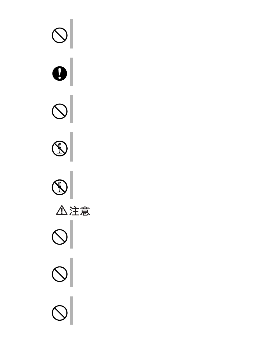
で示した記号は、警告・注意を促す内容であることを
告げるものです。記号の中やその脇には、具体的な警告
内容(左図の場合は感電注意)が示されています。
で示した記号は、してはいけない行為(禁止行為)で
あることを告げるものです。記号の中やその脇には、具
体的な禁止内容(左図の場合は分解禁止)が示されてい
ます。
で示した記号は、必ず従っていただく内容であること
を告げるものです。記号の中やその脇には、具体的な指
示内容(左図の場合は電源プラグをコンセントから抜い
てください)が示されています。
J
i
Page 4
感電
必ず電源を接続する前にアース接続をしてください。
アース接続ができない場合は、弊社担当保守員にご相談くださ
い。
アース接続しないで使用すると、万一漏電した場合に、感電・火
災の原因となります。
窒息
感電
感電
感電
梱包に使用しているビニール袋はお子様が口に入れたり、かぶっ
て遊んだりしないよう、ご注意ください。
窒息の原因となります。
万一、装置から発熱や煙、異臭や異音がするなどの異常が発生し
た場合は、ただちに装置本体の電源スイッチを切り、その後必ず
電源プラグをコンセントから抜いてください。
煙が消えるのを確認して、弊社担当保守員に修理をご依頼くださ
い。
お客様自身による修理は危険ですから絶対におやめください。
異常状態のまま使用すると、感電・火災の原因となります。
異物(水・金属片・液体など)が装置の内部に入った場合は、た
だちに装置本体の電源スイッチを切り、電源プラグをコンセント
から抜いてください。
その後、弊社担当保守員にご連絡ください。
そのまま使用すると、感電・火災の原因となります。特にお子様
のいるご家庭ではご注意ください。
装置を落としたり、カバーなどを破損した場合は、装置本体の電
源スイッチを切り、電源プラグをコンセントから抜いてくださ
い。
その後、弊社担当保守員にご連絡ください。
そのまま使用すると、感電・火災の原因となります。
ii
感電
装置の上または近くに「花びん・植木鉢・コップ」などの水が
入った容器、金属物を置かないでください。
感電・火災の原因となります。
Page 5
感電
台所など湿気・ほこり・油煙の多い場所、通気性の悪い場所、火
気のある場所に置かないでください。
故障・感電・火災の原因となります。
感電
感電
感電
感電
感電
風呂場、シャワー室などの水場で使用しないでください。
感電・火災の原因となります。
表示された電源電圧以外の電圧で使用しないでください。
また、タコ足配線をしないでください。
感電・火災の原因となります。
近くで雷が起きた時は、電源コードをコンセントから抜いてくだ
さい。
そのまま使用すると、落雷などにより、装置の破壊・感電・火災
の原因となります。
付属の電源コード以外は使用しないでください。
感電・火災の原因となります。
装置に水をかけたり、濡らしたりしないでください。
感電・火災の原因となります。
J
感電
感電
濡れた手で電源プラグを抜き差ししないでください。
感電の原因となります。
電源コードを傷つけたり、加工したりしないでください。
重いものを載せたり、引っ張ったり、無理に曲げたり、ねじった
り、加熱したりすると電源コードを傷め、感電・火災の原因とな
ります。
iii
Page 6
感電
電源コードや電源プラグが傷んだり、コンセントの差し込み口が
ゆるい状態では使用しないでください。
そのまま使用すると、感電・火災の原因となります。
修理は弊社担当保守員にご依頼ください。
発火
感電
感電
感電
発火
電源プラグの金属部分、およびその周辺にほこりが付着している
場合は、乾いた布でよく拭いてください。
そのまま使用すると、火災の原因となります。
開口部(通風孔など)から内部に金属類や燃えやすいものなどの
異物を差し込んだり、落としたりしないでください。
感電・火災の原因となります。
装置本体のカバーや差し込み口についているカバーは、取りはず
さないでください。
内部の点検、修理は弊社担当保守員にご依頼ください。
内部には電圧の高い部分があり、感電の原因となります。
装置をお客様自身で改造しないでください。
感電・火災の原因となります。
装置の開口部(通風孔など)をふさがないでください。
通風孔をふさぐと内部に熱がこもり、火災の原因となることがあ
ります。
iv
けが
けが
装置の上に重いものを置かないでください。また、衝撃を与えな
いでください。
バランスが崩れて倒れたり、落下したりしてけがの原因となるこ
とがあります。
振動の激しい場所や傾いた場所など、不安定の場所に置かないで
ください。
落ちたり、倒れたりしてけがの原因となることがあります。
Page 7
発火
直射日光の当たる場所や炎天下の車内など、高温になる場所に長
時間放置しないでください。
高熱によってカバーなどが加熱・変形・溶解する原因となったり、
装置内部が高温になり、火災の原因となることがあります。
感電
発火
発火
発火
感電
電源プラグを抜くときは電源コードを引っ張らず、必ず電源プラ
グを持って抜いてください。
電源コードを引っ張ると、電源コードの芯線が露出したり断線し
たりして、感電・火災の原因となることがあります。
電源プラグは、コンセントの奥まで確実に差し込んでください。
火災・故障の原因となります。
使用中の装置は布などでおおったり、包んだりしないでくださ
い。
熱がこもり、火災の原因となることがあります。
電源コードを束ねて使用しないでください。
発熱して、火災の原因となることがあります。
装置を移動する場合は、必ず電源プラグをコンセントから抜いて
ください。また、接続ケーブルなどもはずしてください。
作業は足元に十分注意して行ってください。
電源コードが傷つき、感電・火災の原因となったり、装置が落ち
たり倒れたりしてけがの原因となることがあります。
J
発火
長時間装置を使用しないときは、安全のため必ず電源プラグをコ
ンセントから抜いてください。
火災・故障の原因となることがあります。
会社名および製品名は各社の商標または登録商標です。
All Rights Reserved, Coryright© 富士通株式会社 2000-2001
v
Page 8

梱包物を確認してください。
ご使用いただく前に、次のものが梱包されていることをお確かめください。
PG-DTA101/PGBDTA101
● DAT オートローダ(PG-DTA101/PGBDTA101)
●電源分岐ケーブル
●交換コネクタ
●クリーニングカセット
●マガジン
●保証書
●取扱説明書(本書)
PG-DTA102/PGBDTA102
● DAT オートローダ(PG-DTA102/PGBDTA102)
●電源分岐ケーブル
●クリーニングカセット
●マガジン
●保証書
●取扱説明書(本書)
万一不備な点がございましたら、おそれいりますが、弊社担当営業員また
は弊社担当保守員までお申し付けください。
vi
Page 9

目次
1 概要 ................................................................... 1
2 接続のしかた .................................................... 2
2.1 準備................................................ 2
2.2 SCSI ID の設定 ...................................... 2
2.3 オートローダ・オプション・スイッチ .................. 6
2.4 コンフィグレーション・スイッチ ...................... 6
2.5 サーバ本体への装着 .................................. 7
3 操作のしかた .................................................... 8
3.1 フロントパネル各部の名称 ............................ 8
3.2 フロントパネル各部の機能 ............................ 8
3.2.1 LED 表示.......................................... 8
3.2.2 スイッチの機能.................................... 9
3.2.3 LCD 表示......................................... 10
4 データカセットの取り扱い ............................. 11
4.1 データカセット..................................... 11
4.2 マガジンとデータカセットのセット ................... 11
4.3 マガジンとデータカセットの排出 ..................... 14
4.4 マガジンとデータカセットの強制排出 ................. 14
4.5 データカセットのライトプロテクト ................... 16
4.6 データカセットの取り扱い上の注意 ................... 17
J
5 テープヘッドのクリーニング ........................ 18
6
バックアップの運用に関する注意事項
.................... 20
7 取り扱い上の注意 ........................................... 22
8 仕様 ................................................................. 23
付録 LCD メッセージ一覧 ................................. 24
vii
Page 10

1 概要
本製品は、PRIMERGY(プライマジー)用の大容量のデータバックアップ装
置です。
サーバとはSCSI(Small Computer System Interface)インタフェースで接続し
ます。
本製品は次のような特長をもっています。
●データカセット 6 巻を装着しデータ圧縮なしの場合、最大 72GB(PG-
DTA101 / PGBDTA101)、 120GB(PG-DTA102 / PGBDTA102)までバッ
クアップ可能です。
●データ圧縮機能があります。
(データの圧縮率は圧縮するデータにより変化します。)
● 記録フォーマットは、ANSI DDS(Digital Data Storege)規格に準拠して
います。
(PG-DTA101 / PGBDTA101 は DDS3 規格、PG-DTA102 / PGBDTA102 は
DDS4規格に対応しています。)
J
1 概要
1
Page 11

2 接続のしかた
2.1 準備
本製品のドライブ番号(SCSI ID)を設定し、オートローダ・オプションスイッ
チ、コンフィグレーションスイッチの設定を確認した後、サーバ本体に装着
します。
ポイント
サーバ本体、およびソフトウェアの準備については、それぞれの取扱説明
書をご覧ください。
2.2 SCSI ID の設定
本製品のSCSI ID を設定します。
お買い上げ時は「5」に設定されています。
変更の必要がある場合はドライブ後面のショートジャンパで設定します。
図2-1 PG-DTA101/PGBDTA101の場合
オートローダ
オプション
スイッチ
2
ローダ用
電源コネクタ
ショート
ジャンパ
ドライブ用電源コネクタSCSI コネクタ
Page 12
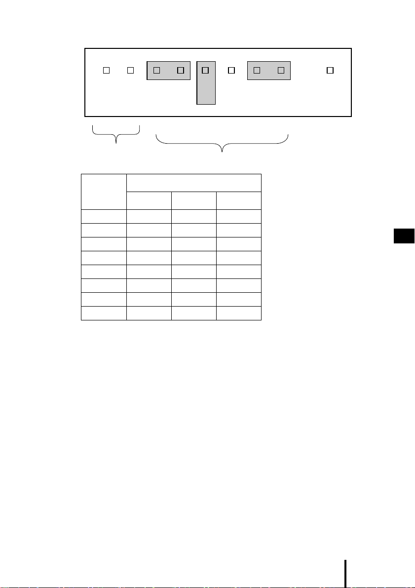
図2-2 ショートジャンパの設定
Termination
Power
SCSI ID
番号
0
1
2
3
4
5*
6
7
*:出荷時設定
SCSI 2
SCSI ID
ショートジャンパ
SCSI 2 SCSI 1 SCSI 0
オープン オープン オープン
オープン オープン ショート
オープン ショート オープン
オープン ショート ショート
ショート オープン オープン
ショート オープン ショート
ショート ショート オープン
ショート ショート ショート
SCSI 0SCSI 1
J
2 接続のしかた
3
Page 13
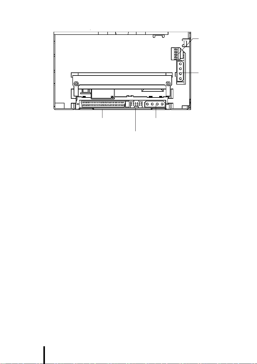
図2-3 PG-DTA102/PGBDTA102の場合
ショートジャンパ
オートローダ
オプション
スイッチ
ローダ用
電源コネクタ
ドライブ用電源コネクタSCSI コネクタ
4
Page 14
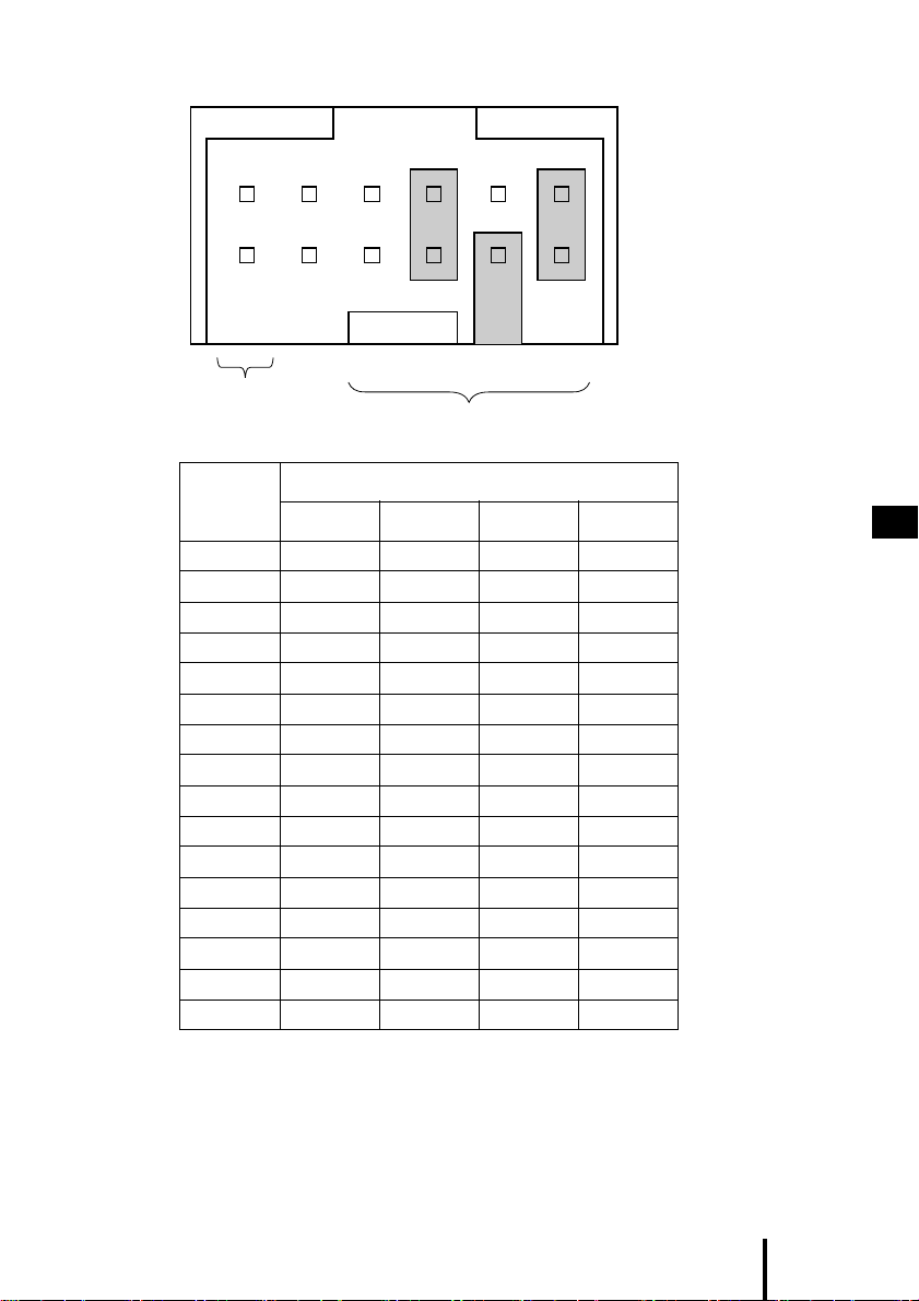
図2-4 ショートジャンパの設定
SCSI 3 SCSI 1SCSI 2 SCSI 0
Termination
Power
SCSI ID
SCSI ID
番号
0
1
2
3
4
5*
6
7
8
9
10
11
12
13
14
15
*:出荷時設定
ショートジャンパ
SCSI 3 SCSI 2 SCSI 1 SCSI 0
オープン オープン オープン オープン
オープン オープン オープン ショート
オープン オープン ショート オープン
オープン オープン ショート ショート
オープン ショート オープン オープン
オープン ショート オープン ショート
オープン ショート ショート オープン
オープン ショート ショート ショート
ショート オープン オープン オープン
ショート オープン オープン ショート
ショート オープン ショート オープン
ショート オープン ショート ショート
ショート ショート オープン オープン
ショート ショート オープン ショート
ショート ショート ショート オープン
ショート ショート ショート ショート
J
2 接続のしかた
5
Page 15
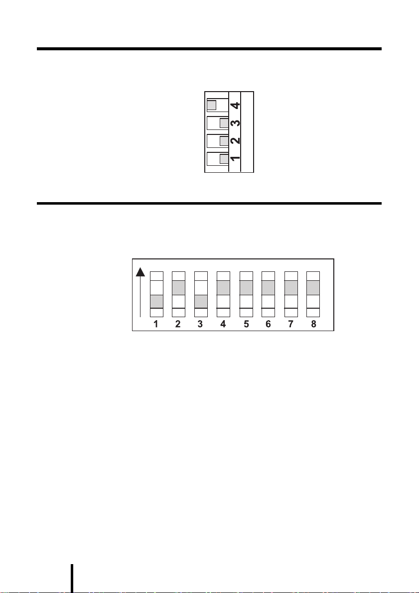
2.3 オートローダ・オプション・スイッチ
オートローダ・オプション・スイッチの設定は変更しないで下さい。
設定が図のとおりであることを確認してください。
2.4 コンフィグレーション・スイッチ
本製品は、装置裏面にコンフィグレーション・スイッチがあります。設定を
変更しないでください。コンフィグレーション・スイッチの設定が図のとお
りであることを確認してください。
ON
6
Page 16
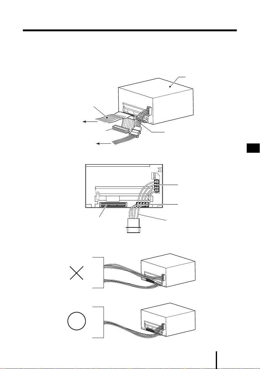
サーバ本体への装着
2.5
装着の前に、サーバ本体の電源を必ず切って下さい。装着方法の詳細は、サー
バ本体に付属の取扱説明書をご覧下さい。PG-DTA101/PGBDTA101 の場合
は、付属の変換コネクタを装置に取り付け、SCSIケーブルに接続してくださ
い。
SCSI ケーブル
サーバへ
サーバ電源へ
電源の接続には添付の電源分岐ケーブルをお使い下さい。
終端抵抗
オートローダ
電源分岐ケーブル
J
ローダ用電源コネクタ
ドライブ用電源コネクタ
SCSI コネクタ
電源分岐ケーブルがない場合などは、下図のように同じ電源ラインを使うようにし
て下さい。
サ
ー
バ
電
源
サ
ー
バ
電
源
電源分岐ケーブル
2 接続のしかた
7
Page 17
3 操作のしかた
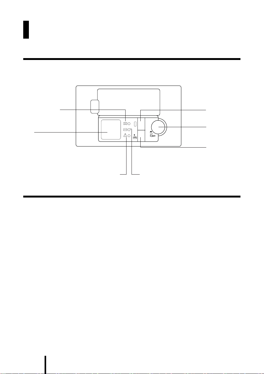
3.1 フロントパネル各部の名称
図3-1 フロントパネル
マガジンセット
LED
LCD
3.2 フロントパネル各部の機能
3.2.1 LED表示
前面パネルには次の3 つのライト (LED) があります。
(1) マガジンセットLED(一番上のLED)
● オートローダ内にマガジンがセットされているときは緑色点灯します。
● マガジンのセット中、チェック中、排出中のときは緑色点滅します。
(2) テープセットLED(真中のLED)
●ドライブ内にデータカセットがセットされているときは緑色点灯しま
す。
●データの読み込み、書き込み中は緑色点滅します。
●データカセットのセット中、排出中のときはゆっくりと緑色点滅しま
す。
データカセッ
ト選択ボタン
排出ボタン
テープセット
ボタン
テープセット LED注意 LED
8
Page 18

(3) 注意LED(一番下のLED)
異常時に黄色点灯します。
●ハードウェアエラーが発生したときは黄色点灯します。
●ユーザレベルで対応できるエラーが発生したときは黄色点滅します。
– ヘッドのクリーニングが必要な場合
– ご使用のテープが寿命に近づいた場合
– オートローダ内にテープはセットされているが、マガジンがセットさ
れていない場合
– フロントパネルのドアが開いている場合
LCDの上段のメッセージを見てください。その後、「付録 LCDメッセージ
一覧」を 参 考にして処置してください。処置を行っても注意 LEDが消えない
場合には、弊社担当保守員へご連絡ください。
3.2.2 スイッチの機能
(1) データカセット選択ボタン
マガジンが本体にセットされているときにこのボタンを押すと、マガジ
ン内のデータカセットを選択することができます。ボタンを何回か押す
と、マガジン内で使用可能なデータカセットが次々にディスプレイに表
示されます。
テープセットボタン
(2)
このボタンを押すと、選択されたデータカセットがマガジンからドライ
ブにセットされます。
(3) 排出ボタン
このボタンを押すと、排出処理が開始されます。現在セットされている
データカセットがドライブから排出され、チェンジャメカニズムによっ
てマガジンに戻されます。その後、マガジンが排出されます。排出ボタン
は緊急時に強制的に排出を行う際にも使用します。「4.4 マガジンとデー
タカセットの強制排出」をご覧ください。
J
3 操作のしかた
9
Page 19
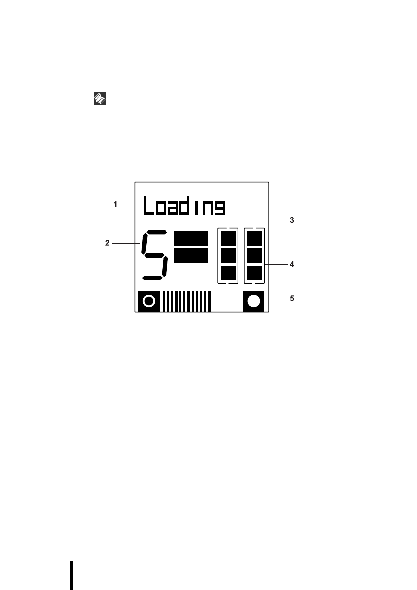
3.2.3 LCD表示
LCDは5 つの表示領域に分かれており、オートローダのステータスに関する
情報が表示されます( 図 3-2 参照)。
下に示すディスプレイではすべての表示領域が同時に表示されています
が、これはどの場所でどのような表示がされるのかを示したものです。実
際にはこのように表示されることはありません。
図3-2 LCD
文字表示ディスプレイ
データカセット番号
ディスプレイ
1 文字表示ディスプレイは、ドットマトリックス方式のディスプレイで最大
10文字を表示することができます。このディスプレイにはオートローダの
動作状況やエラーの状態が表示されます。表示されるメッセージについて
は付録LCD メッセージ一覧を参照してください。
2 データカセット番号ディスプレイには、現在ドライブにセットされている
データカセットの番号が表示されます。また、選択ボタンを押すと、選択
されたデータカセットの番号がここに表示されます。
3LCDの中心部には DC と WPと書かれたインディケータがあります。DC イ
ンディケータは書き込み時にデータ圧縮が行われると表示されます。ま
た、データカセットがライトプロテクトされていると WP インディケータ
が表示されます。
4LCDの右半分には、1 ~ 6 の番号が付いたマガジン内データカセットボッ
クスがあります。どのマガジンスロットにデータカセットがセットされて
いるのかを示します。
5LCDの下の方にはテープ使用量表示があり、現在のパーティションにおけ
るテープの使用量が示されます。縦のラインがたくさん表示されているほ
ど、多くのテープ領域が使用されていることを表します。
ポイント
DC
WP
データ圧縮インディケー
4
1
5
2
6
3
タおよびライトプロテク
トインディケータ
マガジン内データ
カセットアイコン
テープ使用量表示
10
Page 20
4 データカセットの取り扱い
データカセット
4.1
本製品には、必ず下記のデータカセットをお使いください。
品 名 商品番号
データカセット DAT CT20000
データカセット DAT CT12000
データカセット DAT CT4000
データカセット DAT CT2000
データカセット DAT CT1300
○:退避(ライト)・復元(リード)が可能です。
△:復元(リード)のみ可能であり、退避(ライト)はできません。
×:使用できません。
ポイント
データカセットの寿命について
カセットテープは消耗品であり、使用回数に限りがあります。75回を目
安にしてください。なお、お使いになる環境(温度、湿度など)や使用方
法、装置のクリーニング状況によってはテープの傷みが早い場合もあり
ますので、早めの交換をお薦めします。
データカセットの使用開始日をラベルに記入しておくと、寿命の目安に
なります。
マガジンとデータカセットのセット
4.2
0121190
0121180
0121160
0121150
0121110
GP5-DTA101
GP5BDTA101
×○20GB(150m テープ )
○○12GB(125m テープ )
○○4GB(120m テープ )
○△2GB(90m テープ )
○×1.3GB(60m テープ )
GP5-DTA102
GP5BDTA102
備 考
J
マガジンは下記にて手配できます。
品 名 商品番号 備 考
DDS オートローダマガジン
4 データカセットの取り扱い
0611510
11
Page 21
ポイント
●マガジンラベルを使用する場合は、ラベルがマガジン側面のくぼみに
しっかりと貼られていることを確認してください。ラベルが他の場所
に貼られていると、ジャムを起こすおそれがあります( 図4-1 を参照)。
また、ラベルが表面にしっかりと貼り付けられて、端の部分がカールし
ていないことも確認してください。
●データカセットにラベルを貼るときは、1枚だけを決められた位置に貼
るようにしてください。指定以外のラベルを使用したり、決められた場
所以外のところにラベルを貼り付けることは絶対にやめてください。
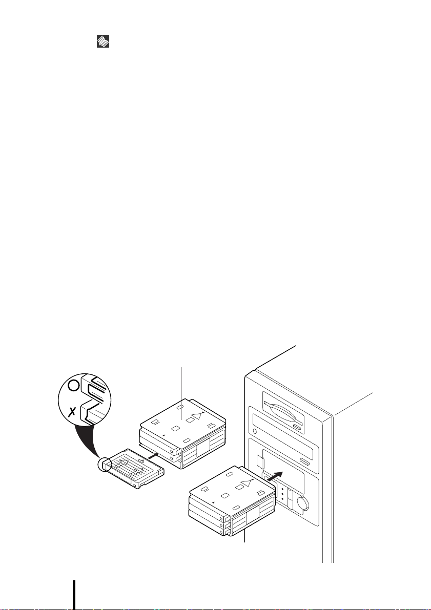
1) 必要な数だけデータカセットをマガジンにセットします。セットすると
きはデータカセットをマガジンの中心に向かって挿入します ( 図4-1 を参
照 )。データカセットの番号は 1 ~ 6 のどの番号を使用してもかまいませ
んし、どのスロットにセットしても結構です。
2) 本製品には自動セットメカニズムが搭載されています。マガジンをセッ
トするときは、オートローダの前面にあるスロットに挿入してください。
このとき、上部の矢印がオートチェンジャの方を向くようにして挿入し
ます( 図 4-1 を参照 )。マガジンが自動的にオートローダ内部に引き込まれ
るまで押し込んでください。
図4-1 マガジンとデータカセットのセット
データカセットをマガジン
にセットする
ここにラベルを貼らないで
ください。
12
オートローダにマガジンを挿入する
Page 22

ポイント
データカセットとマガジンのラベルがラベル貼り付け位置にしっかりと
貼られていることを確認してください。ジャムを起こさないようにする
ために次のことを守ってください。
●ラベルがはがれた状態で使用しないこと。
●貼り付け位置からはみ出している状態で使用しないこと。
●データカセットの端の部分でラベルが折れ曲がっている状態で使用し
ないこと。
●ラベルの上に別のラベルをはった状態で使用しないこと。
3) オートローダはどのマガジンスロットにデータカセットがセットされて
いるのかをチェックします。このプロセスは約20秒かかります。
Windows 2000 使用時の注意
Windows 2000 をご使用になる場合について
Windows2000 ではマガジンをセットせずに起動した場合、下記エラーが発生し
オートローダが正常に認識されません。Windows2000 起動前にマガジンをセット
するようにしてください。
**管理者警告**
デバイス Changer0 の構成に失敗しました。詳細について
はイベントログを参照してください。
イベントビューアでシステムログを確認するとRemovable Storage Serviceが下記内
容のエラーとなります。
J
自動構成ライブラリユニット Changer0 を構成できませ
ん。ライブラリユニットの現在のセットアップは、自動
構成をサポートしていません。
可能な場合、ライブラリの現在のセットアップを変更し
て自動構成ガイドラインに従うか、または手動でデバイ
スを構成してください。
このようなエラーが発生した場合には、マガジンをセットしてサーバーを再起動
するか、下記手順に従って Removable Storage サービスを再起動してください。
①「スタート」ボタンから「プログラム (P)
ス」を選択します。
②表示されるサービスの中から「Removable Storage」をダブルクリック します。
③「停止」ボタンをクリックします。
④ オートローダにマガジンを挿入します。
⑤「開始」ボタンをクリックします。
4 データカセットの取り扱い
」を選択し、「管理ツール」の「サービ
13
Page 23

4.3 マガジンとデータカセットの排出
データカセットがオートローダにセットされている状態で排出ボタンを押
すとマガジンが排出されます。
ポイント
ホストからのコマンドにより、排出ボタンを無効設定にすることができ
ます。この場合は、排出ボタンを押しても何も起こりません。
4.4 マガジンとデータカセットの強制排出
ポイント
強制排出をするとデータが失われる場合があります。また、強制排出では
エンド・オブ・データのマークの書き込みが行われませんので、テープの
フォーマットが無効になることがあります。したがって、強制排出はデー
タカセットを回収する最後の手段としてのみ使用するようにし、データ
カセットを急いで取り出すときの手段として使用することは絶対にやめ
てください。
ドライブの使用中に排出ボタンを押すと、ボタンに反応するまで少し時間が
かかります。
排出ボタンを押してしばらくしても装置が動作せずマガジンが排出されな
い場合のみ次の方法で強制排出を行います。
14
1) 最低 5 秒間、排出ボタンを押したままの状態にします。すると、LCD に
ForceEject( 強制排出 ) と表示されます。
2) オートチェンジャは35 秒間、通常の排出操作を受け付ける状態で待機し
ます。
3) この時間が経過してもドライブ内にテープがあるときは、そのときドラ
イブの行っている動作に関係なく直ちにテープが解放されデータカセッ
トが排出されます。データカセットはマガジンを元の位置に戻し、マガジ
ン自体も排出されます。この後、ドライブはリセットされますが、これは
いったん電源を切って再度入れたときと同じ効果があります。
Page 24

4) ドライブにデータカセットがセットされていない場合、オートローダは
マガジンの排出が要求されたものと見なし、35 秒経過後にこれを行いま
す。この後、オートチェンジャはリセットされますが、これはいったん電
源を切って再度入れたときと同じ効果があります。
ポイント
ホストからのコマンドにより排出ボタンが無効設定されていても、強制
排出の操作が行われると無視されます。また、実行中の
されることがあります。
SCSI
動作も中断
J
4 データカセットの取り扱い
15
Page 25

4.5 データカセットのライトプロテクト
データカセットのデータを変更されたり上書きされたりしないように、ライ
トプロテクトをかけることができます。
データカセットにライトプロテクトをかけるときは、データカセット背面に
あるつまみを動かし、小窓が開いた状態にします( 図 4-2 を参照)。
図4-2
プロテクトされていない状態
プロテクトされていない状態
プロテクトされていない状態プロテクトされていない状態
データカセットを書き込み可能
にするときは、つまみを動かし
て小窓が閉じた状態にします。
ライトプロテクトされた状態
ライトプロテクトされた状態
ライトプロテクトされた状態ライトプロテクトされた状態
データカセットにライトプロテ
クトをかけるときは、つまみを
動かして小窓を開いた状態にし
ます。
ポイント
ライトプロテクトはソフトウェアによるデータの誤消去を防止します。
ライトプロテクトしていても、消磁器等による磁気的なデータの消去を
防ぐことはできません。
16
Page 26

データカセットの取り扱い上の注意
4.6
●テープには触れないでください。また、テープ面やデータカセット内部
のテープガイドを清掃することはおやめください。
●データカセットを極端に湿度の高いところや乾燥したところに放置し
ないでください。
●データカセットを直射日光の当たる場所や磁気を帯びた場所(例:電話機
の下や変圧器のそば)に放置しないでください。
●データカセットを落としたり、乱暴な取り扱いをしないようにしてくだ
さい。
● 複数のラベルをデータカセットに貼らないようにしてください。ドライ
ブ内でジャムを起こす原因となります。
●データカセットを使用しないときはプラスティックケースに保管して
おいてください。
●データカセットはきれいな場所でご使用ください。
●寿命を迎えたデータカセットは使用しないでください。
温度について
10℃~35 ℃の温度下でご使用ください。
動作限界を超える温度下にデータカセットを放置した場合は、適正な温度に
なるまで待ってからご使用ください。これを行うためには、データカセット
を動作温度に最低でも2 時間はなじませる必要があります。
J
温度によるトラブルを避けるために次のことを守ってください。
●ドライブを設置するときは、第2章の記載に従ってください。
● 過酷な温度条件の下にデータカセットを放置しないでください。たとえ
ば、直射日光の当たる車内などがこれに相当します。
4 データカセットの取り扱い
17
Page 27

5 テープヘッドのクリーニング
ポイント
本製品は、データの書き込み・読み取りに磁気ヘッドを使っています。
ヘッドがほこりやゴミなどで汚れていると、データの書き込み・読み取り
が正常に行われません。また、データカセットの寿命が短くなる、データ
カセットのテープ表面に傷が発生し使用できなくなる、ヘッドに汚れが
こびりついて装置が使用できなくなる等の不具合が発生します。
このようなことを未然に防ぐために、クリーニングカセットによる定期
的な清掃(テープヘッドのクリーニング)を必ず実施してください。
クリーニングカセットは下記のものをお使いください。
品 名 商品番号 備 考
クリーニングカセット DAT-N
テープヘッドは以下を目安に清掃してください。
● 使用時間が 24時間ごとに 1回の割合で清掃してください。
● LCD に Clean Me( 清掃してください ) が表示され、注意 LED が点滅した
とき清掃してください。
0121170
18
次のようにしてヘッドを清掃します。
フロントパネルを使ってクリーニングするとき
1) クリーニングカセットをマガジンスロットにセットし ( どのスロットで
もかまいません。)、マガジンをオートローダに挿入します。
2) 選択ボタンを押して、クリーニングカセットをセットしたスロットを選
択します。
3) セットボタンを押して、クリーニングカセットをドライブにセットしま
す。この後、オートローダは自動的にクリーニングを実行します。実行中
は、Cleaning(クリーニング中 ) というメッセージがLCD に表示されます。
Page 28

4) クリーニングが終わると、クリーニングカセットは自動的にマガジンに
戻されます。
5) クリーニングカセットのラベルに日付を記入し、使用回数の記録をつけ
ます。
クリーニングカセットの寿命について
クリーニングカセットは、50回使用すると寿命となります。クリーニング前
にかならずテープ残量を確認してください。
マガジンにクリーニングカセットを常時装備している場合は、寿命を越えな
いように使用回数を管理してください。
クリーニングカセット内の右リールにすべてのテープが巻付いていれば寿
命です。
ポイント
寿命になったクリーニングカセットを使用すると、LCDに“Clean Fail”
と表示されます。
J
5 テープヘッドのクリーニング
19
Page 29

6 バックアップの運用に関する注意事項
●ヘッドクリーニングの実施
磁気テープ装置では、磁 気媒体から染み出る汚れや浮遊 塵埃 により、
ヘッド汚れが発生し、これらの汚れを取り除くためにヘッドクリーニン
グが必要です。装置がクリーニング要求を表示した場合にヘッドクリー
ニングを実施することはもとより、特に要求が発生しなくとも定期的に
ヘッドクリーニングする運用を推奨します。
また、クリーニング媒体は使用回数に限度があるので、寿命を管理して
ください。寿命の過ぎたクリーニング媒体を使用してもクリーニング効
果はありません。オートローダ装置での自動バックアップでは、クリー
ニング媒体の使用回数に注意してください。
● 媒体の寿命管理
テープ媒体は消耗品であり、定期的な交換が必要です。
寿命の過ぎた媒体を使用し続けるとヘッド汚れを加速するなど、装置に
悪影響を与えます。媒体の寿命は、装置の設置環境/動作状態/バック
アップソフトウェアの種類/運用条件により大きく変化しますが、早め
の交換を推奨します。
寿命の目安とするため、媒体に使用開始日を表示してください。
● 媒体のローテーション運用
1 巻の媒体でバックアップを繰り返すような運用では、バックアップに
失敗した場合、一時的にでもバックアップデータが無くなる状態になり
ます。また、バックアップ中にハードディスクが壊れたような場合には、
復旧不可能な状態になります。
したがって、バックアップは数本の媒体をローテーションして運用して
ください。
● 媒体入れ放し運用の禁止
媒体は装置内では磁気記録面が露出しており、この状態が長く続くと浮
遊塵埃の影響を受けやすくなります。この状態が少なくなるように媒体
は使用前に装置にセットし、使用後は取り出して、ケースに入れて保管
してください。
また、磁気テープ装置では、媒体が取り出される時にテープに管理情報
の書き込み処理を行うものがあります。装置に媒体を入れたまま電源を
切断するとこの処理が行われないため、異常媒体が作成される場合があ
ります。
サーバの電源を切断する場合は、装置から媒体を取り出してください。
20
Page 30

●バックアップ終了後の媒体の排出
バックアップソフトウェアには、バックアップ終了後に媒体をドライブ
から排出するように指定できるものがあります。この指定を行うとバッ
クアップ終了後にテープが巻き戻され、媒体がドライブから排出されま
す。
オートローダ装置では必ず本機能の実行を指定してください。
なお、本指定を行うとサーバの構造によっては排出された媒体がドライ
ブを覆う筐体カバーに当たる場合があります。この場合はカバーを開け
ておくか媒体の排出は行わないようにしてください。
●バックアップ終了後のデータの検査
バックアップソフトウェアには、バックアップ終了後に“データの検査”
の実行を指定できるものがあります。この指定を行うとバックアップ終
了後に媒体に書き込んだデータを読み出して、書き込み内容の検査が行
われますので、信頼性は高まります。
一方、バックアップ業務に要する時間が長くなったり、媒体の使用回数
が増えることによる媒体の寿命低下、といった短所もありますので、留
意してください。
● 媒体ラベルの種類と貼り付け位置
媒体に名前等を表示する場合は、媒体に添付されているラベルを使用し
てください。
また、媒体にはラベルを貼る個所が決められています。装置故障の原因
となりますので、決められた以外の所にはラベルを貼らないようにして
ください。
●データの保管
データを長期に保管する場合は、温湿度管理され、磁場の影響の少ない
場所に保管してください。
● 媒体エラー(メディアエラー)が発生したとき
バックアップ処理やリストア処理中に媒体エラー(メディアエラー)が
発生することがありますが、この発生要因は以下のいずれかが原因と
なっています。
a) ヘッドが汚れ、データが読みにくくなった。
b) テープ媒体が損傷/磨耗するなどしてデータが読みにくくなった。
前者の場合には、テープを新品に交換しても効果はありません。
したがって、媒体エラーが発生した場合には、以下の手順でリカバリし
てください。
1)テープ装置のクリーニングを行う。
2)エラーが発生したテープ媒体を装着して、処理を行う。
3)再度エラーが発生した場合には、媒体が損傷/磨耗していると思われ
るため、新品のテープと交換する。
J
バックアップの運用に関する注意事項
6
21
Page 31

7 取り扱い上の注意
本製品は精密機器ですので、以下のことに注意してください。
● 極端な高温や低温の場所、または温度変化の激しい場所での保管は避け
てください。
● 直射日光のあたる場所や発熱器具のそばには近づけないようにしてく
ださい。
●衝撃や振動の加わる場所での保管は避けてください。
●湿気やほこりの多い場所での使用は避けてください。
● 内部に液体や金属など異物が入った状態でお使いにならないでくださ
い。もし、何か異物が入ったときは、お買いあげの販売店または担当保
守員にご相談ください。
●サーバ本体の電源を切断するときは、データカセットを取り出してくだ
さい。
● 本製品前面の汚れは、やわらかい布でからぶきするか、布に水または中
性洗剤を含ませて、軽くふいてください。ベンジンやシンナーなど揮発
性のものは避けてください。
● 寒い場所から暖かい場所に移動したり、室温を急に上げたりした直後
は、内部が結露する場合があります。結露したままお使いになると、本
製品やデータカセットを損傷することがあります。大きな温度変化が
あったときは、2時間以上待ってから電源を入れてください。
● お使いにならないときは、本製品からデータカセットを取り出してくだ
さい。また、データカセットを入れたまま本製品を持ち運ばないでくだ
さい。
● 本製品を分解したり、解体したりしないでください。
● オートローダの装置内部には DAT ドライブがあり、このドライブ内に
データカセットが入った状態で電源が切断されるとデータが保証でき
ず、媒体エラーとなることがあります。
バックアップソフトの設定で、“最後にバックアップメディアをイジェ
クト”(テープをイジェクト等、ソフトウェアにより表現が異なる場合が
あります)を必ず指定して下さい。この指定を行うとバックアップ終了
後にカセットはドライブから排出され、マガジンに戻されます。
● ARCserve の“クイック初期化”について
ARCserveでは設定により、テープエンジン起動時のテープのインベント
リ処理実行を省略することができます。本機能は以下の点に注意して設
定して下さい。
クイック初期化を有効にした場合
・テープエンジン起動時のテープの読み込み処理が省略され、媒体
の消耗を少なくすることができます。
・テープを入れ替えた場合はインベントリ処理を手動で実行する必
要があり運用上の注意が必要です。
22
Page 32

8 仕様
品名 内蔵 DDS3 オートローダ 内蔵 DDS4 オートローダ
型名
質量
外形寸法 幅 146.1mm ×奥行 203.2mm ×高さ 82.6mm
記憶容量 12GB(非圧縮時)× 6 巻 20GB(非圧縮時)× 6 巻
実効データ転送速度
記録密度
トラック密度
装置寿命 5 年または 6000 時間(動作時間)
エラーレイト
インタフェース
環境条件 温度 10 ℃~ 35 ℃(稼動時)
温度勾配 10 ℃/ H(稼動時)
湿度 20%~ 80%RH(結露なきこと)
最大湿球温度 26 ℃
消費電力 最大 60W
PG-DTA101
PGBDTA101
2.2kg 2.0kg
(ベゼル・コネクタ部含まず)
1.0MB/s 3.0MB/s
122,000 bpi 122,000 bpi
2793 tpi 3738 tpi
-15
bit 以下(回復不可能なエラー)
10
Narrow Single Ended SCSI Ultra Wide LVD SCSI
- 5 ℃~ 55 ℃(休止時)
20 ℃/ H(休止時)
PG-DTA102
PGBDTA102
J
8 仕様
23
Page 33

付録 LCDメッセージ一覧
メッセージの種類
E:エラーメッセージ
I:インフォメーションメッセージ
S:ステータスメッセージ
LCD メッセージ
At BOD E
At EOD E
Bad Media E
Cannot Write
Non-MRS Tape
Clean fail:
Check Cleaning
Tap e
Clean Me E
Cleaning S
Close Door E
Drive Comms Error E
Drive fault E
Eject fail E
種類
注意 LED
の動作
点灯 SPACE コマンドで予期しないBOD(Beginning of Data) を
検出しました。テープ位置は現在 BOD です。
点灯 READ または SPACE コマンドで予期しない EOD(End of
Data) を 検出しました。テープ位置は現在 EOD です。
点滅 テープが DDS フォーマットでないため、READ または
SPACE コマンドが失敗しました。テープを排出し、DDS
規格のテープ (Media Recognition System テープ ) を使用
してください。
E
点滅 WRITE, WRITE FILEMARK または ERASE コマンドを
Media Recognition System テープでないテープに対して
実行しようとしました。
デー タカセットを取り出 し、Media Recognition System
テープに交換してください。
E
点滅 クリーニングカセット が寿命に達しているためクリー
点滅 リードまたは ライト時に高いエラーレートを検出しま
点滅 フロントパネルドアが開いているためオートローダが
点灯 ドライブとローダメカニズムとの通信ができません。
点滅 排出ボタンが押された後または排出コマンドの後、排出
ニングに失敗しました。
新しいクリーニングカセットを使用してください。
した。
使用可能なクリーニングカ セットを挿 入してテ ープ
ヘッドを清掃してください。
- ドライブにクリーニングカセットがロードされました。
動作できません。
これはマガジンが完全に挿入されていないと きなどに
起こります。マガジンを完全に挿入するか抜いて下さ
い。
弊社担当保守員に連絡してください。
- ドライブが内部エラーを検出しました。
に失敗しました。
強制排出を試してください。
意 味
24
Page 34

Eject Mag I
Erase S
Error X E
ForceEject I
Format S
FW Check S
FW Data Err E
FW Program S
FW Tape S
FW Upgrade S
FW Read Fail E
FW Tape Write
Protected
FW Write Fail E
Insert Mag S
Load Fail:
Try New Tape
Load Fail:
Press Eject
- 排出ボタンを押したとき表示されます。
- テープのデータを消去しています。
点滅 ハードウェアエラーです。X はエラーの種類を表しま
す。
排出ボタンを押しカセットとマガジンを取り出して下
さい。問題が解決しない場合は X の値を記録して弊社
担当保守員に連絡してください。
- 強制排出中です。
-1つまたは2つのパー ティションを作 成 するための
SCSI コマンドが実行中または2パーティションのテー
プのパーティションの大きさを変更しています。
- ファームウェア・アップグレード・データの互換性を確
認しています。
点滅 新しいフ ァ ー ムウェアが不正な ためオートローダは
点滅 テープからのデータの読み取りでエラーが起こったた
E
点滅 テープが書込み禁止のためファームウェアのアップグ
点滅 テープへ の 変更回数 の書込みがエラーとなったため
E
点滅 load コマンドが失敗したか、load または change partitions
E
点滅 load コマンドが失敗したか、load または change partitions
ファームウェアのアップグレードに失敗しました。
正しいファームウェアを使用してください。
- ドライブは新しいファームウェア にアップグレード中
です。
- ドライブにロードされたテープはファームウェア・ア ッ
プグレード・テープです。
- テープからファームウェア・ア ッ プグ レード・データを
読み取り中です。
めファームウェアのアップグレードに失敗しました。
もう一度やり直してください。それでも失敗する場合は
弊社担当保守員に連絡してください。
レードに失敗しました。
テープを書き込み可能にしもう一度やり直してくださ
い。
ファームウェアのアップグレードに失敗しました。
もう一度やり直してください。それでも失敗する場合は
弊社担当保守員に連絡してください。
- マガジンを挿入してください。
コマンドがテープのシ ステム領域の読取りに 失敗しま
した。
新しいデータカセットを使用してください。
コマンドがテープのシ ステム領域の読取りに 失敗しま
した。
排出ボタンを押して下さい。
J
付録 LCD メッセージ一覧
25
Page 35

Load Lock I
Load Tape I
Loading S
Locate S
Mag Check S
Mag Eject S
Mag Loaded S
Media Removal
Prevented
New FW!!!! S
No EODmark E
Partition S
Partition 1 too large E
Press Eject I
Read S
Read Fail E
Rewind S
SCSI Error E
Search << S
Search >> S
Select Lock I
Select Tape I
- 手動のロードはできません。(PREVENT MEDIA
REMOVAL コマンドが発行されています。)
- テープセットボタンを押したとき表示されます。
- マガジンから ドライブへデータカセットを移動してい
るか、ドライブがデータカセットをロードしています。
-ホストから指定されたテープ位置に移動中です。
- オートローダはマガジンのどのス ロットにテープが挿
入されているのか確認しています。
- マガジンを排出しています。
- オートローダにマガジンが挿入されマガジンのチェッ
クが完了しました。
E
点灯 PREVENT MEDIA REMOVAL コマンド が発行された
後、排出コマンドを実行しようとしました。
ALLOW MEDIUM REMOVAL コマンドを発行するか、
オートチェンジャをリセットまたは再起動してからも
う一度やり直してください。
- ファームウェアのアップグレードが完了しました。
点滅 ブランク・テープ(DDS フォーマットの EOD パターン
のないもの)をリードしようとしました。書込みの際に
電源が切れた可能性があります。
- 2 パーティション・テープで別のパーティションに移動
中です。
点灯 パーティション1に指定されたサ イズが大きすぎるた
点滅 リードに失敗しました。
点灯 SCSI コマンドエラーが検出されました。
めテープのフォーマットに失敗しました。
パーティション1のサイズを小さくするか、可能な場合
は容量の大きいテープを使用して下さい。
- 排出ボタンを押して下さい。
- テープからデータを読んでいます。
リポジションしてやり直す必要があります。
- テープをパーティション先頭まで巻き戻しています。
SCSI インタフェースの接続を確認しやり直して下さ
い。
- ド ライブ は record, filemark, setmark, BOD(Begining of
Data) を テープの先頭方向に向かって検索中です。
- ドライブは recode, filemark, setmark, EOD(End of Data) を
テープの終端方向に向かって検索中です。
- デ ー タカセットの選択はできませ ん。(PREVENT
MEDIUM REMOVAL コマンドが発行されています。)
- データカセッ ト選択ボタンを押して離した後の短い間
表示されます。
26
Page 36

Self Test S
SemiLoaded S
Stray Tape:
Insert Empty Mag
Tap e Fau l t E
Tap e Ful l E
Tape has DC data E
Tape Position Lost E
Tap e Stu c k E
Unloading S
UpgradeErr E
Worm Media E
Write x.y S
- 電源投入後の自己診断を実行中です。
- カセットはドライブ内にありますがロードされていま
せん。(テープはカセットから引き出されていません。)
I
- カセットがドライブ内にありますがマガジンが挿入さ
れていません。
カセットを回収するために空のマ ガジンを挿入してく
ださい。
点滅 ドライブ内のテープに欠陥があります。
新しいデータカセットを使用して下さい。またそれが
Media Recognition System 対応 であることを 確認してく
ださい。
点灯 READ, SPACE, WRITE, WRITE FILEMARKSコマンドで
予期せぬ EOP(End of Partition) を検出しました。リード
時には次のテープにデータが続く ことを意味する場合
もあります。
点灯 ドライブが圧縮データ を伸長するように設定されてい
ないとき READ コマンドで圧縮されたデータを検出し
ました。ホストがデータ圧縮を無効にしているかコン
フィグレーションスイッチ2がオフになっているため
ホストがドライブの設定を変更できない可能性があり
ます。
ホストがデー タ圧縮を無効にしていないことを確認し
てください。装置底面のコンフィグレーションスイッチ
2 がオンであることを確認してください。
点灯 WRITE, READ, SPACE, REWIND コマンドが完了できま
せんでした。テープが不正なグループに位置していま
す。
リポジションしてやり直してください。
点滅 カセットがドライブ内で動けなくなりました。
強制排出してください。失敗した場合は弊社担当保守員
に連絡してください。
- ドライブがテープをアンロードしているかドライブか
らマガジンへ移動中です。
点滅 ファームウェ アのアップグレード中にエラーになりま
した。
点滅 書込み時のエラー率が高くなっています。テープが寿命
に近づいていると思われます。
新しいデータカセットに必要なデータをコピーして下
さい。古いデータカセットは廃棄してください。
- テープにデータを書込み中です。"x.y:1" は電源投入後
または圧縮率データがクリアされた後からの累積圧縮
率を表します。例えば、"Write 2.1" は圧縮比が 2.1:1 で
あることを意味します。圧縮率は電源投入後、約1 MB
のデータを書き込んだ後でないと表示されません。
J
付録 LCD メッセージ一覧
27
Page 37

Write Fail E
Write Fail:
Clean or Use New
Tap e
Write Protected Tape E
Wrong FW E
点滅 WRITE, WRITE FILEMARK, ERASE コマンドが失敗し
ました。
新しいデータカセットを使用して下さい。
E
点滅 テープに書き込めません。テープが使い古されているか
損傷している可能性があります。
使用可能なクリーニングカ セットを挿 入してテ ープ
ヘッドをクリーニングするか、新しいデータカセットを
使用してください。
点滅 書込 み禁止のカ セットに WRITE, WRITE FILEMARK,
ERASE コマンドを実行しようとしました。
カセットを取り出し書き込み可能にしてください。
点滅 アップグレー ド・フ ァームウェアは適 用できません。
ファームウェアは変更されません。
28
Page 38

■ハードウェアエラー番号の詳細
液晶表示器(LCD)に“Error X”で表示されるハードウェアエラーについて、
詳細情報を以下に示します。
本エラーが表示された場合は、担当保守員へご連絡ください。このとき、“X
の値”につきましても併せてご連絡ください。
X の値
8 ~ 13 DAT テープ垂直搬送機構の異常を検出しました(垂直搬送機構の引っ掛かり等)
16 ~ 21 DAT テープ垂直搬送機構に対し動作を指示しましたが正常に動作しません
24, 25
32 ~ 38 マガジン回転機構の異常を検出しました(回転機構の引っ掛かり等)
40 ~ 46 マガジン回転機構に対し動作を指示しましたが正常に動作しません
48 ~ 55
56 ~ 63 マガジン装着動作中、マガジン搬送機構の異常を検出しました
64 ~ 71 マガシン排出動作中、マガジン搬送機構の異常を検出しました
72 ~ 79 搬送部テープ保持機構の異常を検出しました
80 ~ 87 DAT テープ水平搬送機構に対し動作を指示しましたが正常に動作しません
88 ~ 93 あるべき DAT テープが存在しません
96 ~ 101 マガジン内にセットされた DAT テープの装着状態に関し、装置内部で制御上の矛
104 ~ 107 マガジンが装着されているにもかかわらず、装置前面のドアが開いています
112 ~ 117 DAT テープが搬送部の保持機構から外れました
120 ~ 121 DAT テープのローディングに失敗しました(搬送機構の問題)
128 ~ 132 DAT テープ水平搬送機構の異常を検出しました(水平搬送機構の引っ掛かり)
136 ~ 140 DAT テープ水平搬送機構に対し動作を指示しましたが正常に動作しません
144
152 ~ 159
160, 161
168, 169
176
184, 192, 200
208
216
224
232
240
248
マガジン装着状態に関し、装置内部で制御上の矛盾を検出しました
マガジン装着動作中、水平搬送機構に対し動作を指示しましたが正常に動作しません
盾を検出しました
センサの異常を検出しました
マガジン排出動作中、水平搬送機構に対し動作を指示しましたが正常に動作しません
DAT テープがドライブから異常排出されました
DAT テープのローディングに失敗しました(ドライブの問題)
装置前面ドアの異常を検出しました
未定義または不当な内部コマンドを検出しました
DAT テープの搬送制御で矛盾を検出しました
不当な SCSI コマンドを受信しました(LOG SENSE, LOG SELECT コマンド関連)
ホストコンピュータから1から6 以外DATテープに関するコマンドを受信しました
DAT テープが見つかりません
自己診断が実行されません
表示パネルの異常を検出しました
ハードウェアエラーの詳細
J
付録 LCD メッセージ一覧
29
Page 39

Preface
Thank you for your purchase of the Tape Drive DAT DDS3 Autoloader (PGDTA101/PGBDTA101) / Tape Drive DAT DDS4 Autoloader(PG-DTA102/
PGBDTA102).
This manual provides the basic operating instructions for the DAT Autoloader,
which will be referred to as Òthis productÓ throughout the manual.
Please read this manual carefully and thoroughly before using the DAT Autoloader.
For Your Safety
This manual contains important information you need to know to use this product
correctly and safely.
Read this manual thoroughly before using this product.
Keep this manual in a safe place for future reference.
February 2001
The company names and product names in this guide are trademarks and trade names of their respective owners.
All Rights Reserved, Copyright © FUJITSU LIMITED 2000-2001
Page 40

What’s in the Package
Before using this product, check that all the following items are included in the
package.
PG-DTA101/PGBDTA101
• Tape Drive DAT DDS3 Autoloader (PG-DTA101/PGBDTA101)
• Y power cable
• 50-68 pin connector
• Cleaning cartridge
• Magazine
• Warranty card
• User’s manual (this manual)
PG-DTA102/PGBDTA102
• Tape Drive DAT DDS4 Autoloader (PG-DTA102/PGBDTA102)
• Y power cable
• Cleaning cartridge
• Magazine
• Warranty card
• User’s manual (this manual)
If any item is missing from the package, call your dealer or service representative for
more information.
E
i
Page 41

CONTENTS
1 Introduction ....................................................... 1
2 Installation ......................................................... 2
2.1 Preparation .................................................................................... 2
2.2 Setting the SCSI ID....................................................................... 2
2.3 Autoloader Option Switches ......................................................... 6
2.4 Configuration Switches................................................................. 6
2.5 Installing into the Server ............................................................... 7
3 Operation .......................................................... 8
3.1 Front Panel Part Names................................................................. 8
3.2 Front Panel Functions.................................................................... 8
4 Using Cartridges ............................................. 11
4.1 Cartridges .................................................................................... 11
4.2 Magazine and Cartridge Set........................................................ 11
4.3 Ejecting a Magazine or a Cartridge............................................. 14
4.4 Forced Ejection of a Magazine or a Cartridge ............................ 14
4.5 Write-protecting a Cartridge ....................................................... 16
4.6 Cartridge Handling Precautions .................................................. 17
5 Head Cleaning ................................................ 18
ii
6 Handling Precautions ...................................... 20
7 Specifications .................................................. 21
Appendix LCD Messages .................................. 22
Page 42

1Introduction
This product is a high capacity backup system for use with the PRIMERGY line of
servers using the SCSI (Small Computer System Interface) interface for the connection.
This product comes with the following features:
• A maximum storage capacity of 72 GB (PG-DTA101/PGBDTA101) or 120 GB
(PG-DTA102/PGBDTA102) using 6 cartridges without data compression.
• Supports data compression. (The compression ratio varies depending on the
type of data.)
• ANSI DDS (Digital Data Storage) compliant. (PG-DTA101/PGBDTA101 conforms to the DDS-3 format while the PG-DTA102/PGBDTA102 conforms to
the DDS-4 format.)
1 Introduction
E
1
Page 43

2 Installation
2.1 Preparation
Before connecting this product to the server, make sure to first set the drive’s SCSI
ID number, the autoloader’s option switches, and the drive’s configuration switches.
NOTE:
Refer to the manuals that came with the server and the backup software
for instructions on any necessary preparations.
2.2 Setting the SCSI ID
The drive’s SCSI ID is set to “5” at the time of manufacture. Use the jumpers on the
back of the drive to change the SCSI ID setting.
Figure 2-1 Rear panel of the PG-DTA101/PGBDTA101
Autoloader
option switches
2
SCSI connector
Loader power
connector
Jumpers
Drive power connector
Page 44

Figure 2-2 Jumper settings
SCSI 2
Termination
Power
SCSI ID
Number
0 Open Open Open
1 Open Open Shorted
2 Open Shorted Open
3 Open Shorted Shorted
4 Shorted Open Open
5* Shorted Open Shorted
6 Shorted Shorted Open
7 Shorted Shorted Shorted
* : Factory setting
SCSI 2 SCSI 1 SCSI 0
Jumpers
SCSI 0SCSI 1
SCSI ID
E
2 Installation
3
Page 45

Figure 2-3 Rear panel of the PG-DTA102/PGBDTA102
Autoloader
option switches
Loader power
connector
SCSI connector
Drive power connector
Jumpers
4
Page 46

Figure 2-4 Jumper settings
SCSI 3 SCSI 1SCSI 2 SCSI 0
Termination
Power
SCSI ID
SCSI ID
Number
0 Open Open Open Open
1 Open Open Open Shorted
2 Open Open Shorted Open
3 Open Open Shorted Shorted
4 Open Shorted Open Open
5* Open Shorted Open Shorted
6 Open Shorted Shorted Open
7 Open Shorted Shorted Shorted
8 Shorted Open Open Open
9 Shorted Open Open Shorted
10 Shorted Open Shorted Open
11 Shorted Open Shorted Shorted
12 Shorted Shorted Open Open
13 Shorted Shorted Open Shorted
14 Shorted Shorted Shorted Open
15 Shorted Shorted Shorted Shorted
* : Factory setting
SCSI 3SCSI 2SCSI 1SCSI 0
Jumpers
E
2 Installation
5
Page 47

2.3 Autoloader Option Switches
Do not make any changes to the autoloader’s option switches. Confirm that the
switches are in the positions indicated in the illustration below.
2.4 Configuration Switches
There is a set of configuration switches on the underside of the drive. Do not make
any changes to the configuration switches. Confirm that the configuration switches
are in the positions indicated in the illustration below.
ON
6
Page 48

2.5 Installing into the Server
Make sure that the server’s power is turned off before installing the drive. For
detailed instructions on how to install the drive into the server, refer to the manuals
that came with the server.
SCSI cable
To server
SCSI Terminator
To server power
Use the provided Y power cable to connect the power connectors.
Autoloader
Y power cable
Loader power connector
Drive power connector
Y power cableSCSI connector
If there is no Y power cable, connect the power supply using one power cable as
shown in the illustration below.
P
S
o
e
w
r
e
v
r
e
r
P
S
o
e
w
r
e
v
r
e
r
2 Installation
E
7
Page 49

3 Operation
3.1 Front Panel Part Names
Figure 3-1 Front Panel
Magazine Present
light
LCD
3.2 Front Panel Functions
3.2.1 Front Panel Lights
The front panel has the following 3 lights:
(1) Magazine Present light (upper light)
• Lights up in green when there is a magazine set inside the autoloader.
• Flashes in green when the magazine is being set, checked, or ejected.
(2) Tape Activity light (middle light)
• Lights up in green when there is a cartridge set inside the drive.
• Flashes in green when data is being read or written.
• Flashes slowly in green when a cartridge is being set or ejected.
Select button
Eject button
Load Tape
button
Tape Activity lightOperator Attention light
8
Page 50

(3) Operator Attention light (lower light)
This light lights up in yellow when there are errors.
• Lights up in yellow when a hardware error occurs.
• Flashes in yellow when a user-recoverable error occurs.
– The heads need cleaning.
– The tape is nearing the end of its useful life.
– There is a tape in the autoloader, but no magazine is installed.
– The front panel door is open.
Read the message on the top line of the LCD panel and refer to “LCD Messages” in
the Appendix to take any possible corrective action. If following the instructions
given fail to correct the error, call for service.
3.2.2 Front Panel Buttons
(1) Select button
The Select button allows you to select any of the cartridges in the magazine after
the magazine has been loaded into the Unit. If you press the Select button repeatedly, the display cycles through the cartridges available in the magazine.
(2) Load Tape button
Use the Load Tape button to load the selected cartridge from the magazine into
the drive.
(3) Eject button
The Eject Button starts the unload process. The drive unloads any currently
loaded cartridge, and the changer mechanism returns the cartridge to the magazine. The magazine is then ejected. The Eject button can also be used to force
ejection in an emergency. See “4.4 Forced Ejection of a Magazine or a Cartridge” for details.
3 Operation
E
9
Page 51

3.2.3 Front Panel Liquid Crystal Display (LCD)
The five display regions of the LCD panel provide information about the status of
the autoloader. (See figure 3-2.)
NOTE:
Note that all the possible display regions are shown in figure 3-2 and that
this display can never occur; all the sections are showing at the same
time so that you can see where they are.
Figure 3-2 LCD
10-Character Dot
Matrix display
DC
Cartridge Number
display
1 The 10-character dot matrix display provides information on the autoloader’s
operating status and potential error conditions. Refer to “LCD Messages” in the
Appendix for details of the kinds of messages that can be displayed here.
2 The Cartridge Number display shows the number of the current cartridge loaded
in the drive, or the cartridge selected when you press the Select button.
3 The center of the LCD panel is where DC (Data Compression) and WP (Write-
Protected) are displayed. DC indicates that data compression is being used for
writing, and WP indicates that a cartridge is write-protected.
4 The six numbered boxes on the right of the LCD panel are individually lit to show
which magazine slots contain a cartridge.
5 The display at the bottom of the LCD panel shows how much tape has been used
in the current partition. The more lines shown, the more tape has been used. When
all the lines show, the partition is full.
WP
4
1
5
2
6
3
Data Compression
and Write-Protected
indicators
Loaded Cartridge
indicators
Tape Usage indicator
10
Page 52

4 Using Cartridges
4.1 Cartridges
Always use cartridges specified in the table below.
Product
Name
DG4-150M FUJI PHOTO FILM
DG3-125M O O 12GB(125m tape)
HS-4/120S HITACHI Maxell
HS-4/90S O % 2GB(90m tape)
HS-4/60S O X 1.3GB(60m tape)
O : Read and Write
% : Read only
X : Cannot be used
Supplier
CO.LTD.
Ltd.
NOTE:
Cartridges are consumable products and there is a limit to the number of
passes that they can be used for. Expect the cartridges to withstand 75
passes. The life expectancy of cartridges can vary depending on environmental conditions (temperature, humidity), way of use, and the drive’s
state of cleanliness. It is recommended that you use new tapes sooner
than later. Writing down the date of initial use on the label will help in
knowing when a cartridge is nearing the end of its useful life.
GP5-DTA101
GP5BDTA101
X O 20GB(150m tape)
O O 4GB(120m tape)
GP5-DTA102
GP5BDTA102
Remarks
4.2 Magazine and Cartridge Set
E
A new magazine can be ordered using the information in the table below.
Product Name Part No. Supplier
DDS Autoloader Magazine C1571A Hewlett-Packard Ltd.
4 Using Cartridges
11
Page 53

NOTE:
• Magazine labels must be firmly stuck to the recessed label area on the
side of the magazine and nowhere else. Fixing labels anywhere else
may lead to jams (see figure 4-1). Make sure that labels are firmly
stuck to the surface and not peeling off or curling at the corners.
• Stick only one label on the specified location on cartridges. Do not use
labels that are not supplied with the cartridges and never fix them on
any location other than that specified.
1) Load the required number of cartridges into the magazine by inserting the cartridges towards the center of the magazine (see figure 4-1). You can use any
number cartridge from 1 to 6, and place the cartridges in any of the slots on the
magazine.
2) To install the magazine into the autoloader, insert it into the slot in the front of
the autoloader. Make sure that the arrow on the top of the magazine is pointing
towards the autoloader (see figure 4-1). Apply steady pressure until the mechanism takes the magazine and pulls it into the autoloader.
Figure 4-1 Magazine and cartridge set
Loading cartridges into
the magazine
12
Do not fix labels here
Inserting the magazine into the autoloader
Page 54

NOTE:
Stick magazine and cartridge labels firmly in their proper locations. To
avoid jams, use labels according to the guidelines below:
• Do not use a magazine or a cartridge whose label has peeled off.
• Make sure that labels are not sticking out of their proper locations.
• Make sure that labels on cartridges are not folded on their ends.
•
Do not stick labels on top of other labels.
3) The autoloader automatically checks which magazine slots contain cartridges.
This process takes about 20 seconds.
Notes When Using Windows 2000
Read the following if your operating system is Windows 2000.
The autoloader will not be properly detected if the magazine is not installed inside the autoloader when the system starts up. The following error will be displayed.
**ADMINISTRATOR ALERT**
Configuration for device Changer0 failed. See the
event log for more details.
Looking at the event viewer’s system log will show the following error for Removable Storage Service.
Unable to auto-configure library unit Changer0. The
current setup of the library unit does not support automatic configuration. You will either have to modify
the current setup of the library to adhere to automatic configuration guidelines (if possible) or manually
configure the device.
When such an error occurs, install the magazine into the autoloader and restart
the server. Alternatively, you can follow the steps below to restart the Removable
Storage Service:
(1) Click the [Start] button, point at [Programs] and then [Administrative Tools].
Then select [Services].
(2) Double-click [Removable Storage].
(3) Click the [Stop] button.
(4) Install the magazine into the autoloader.
(5) Click the [Start] button.
4 Using Cartridges
13
E
Page 55

4.3 Ejecting a Magazine or a Cartridge
If the Eject button is pressed when a cartridge is loaded into the drive mechanism,
the autoloader will unload the cartridge and will eject the magazine.
NOTE:
The Eject button can be disabled by sending a host command. In this
case, pressing the Eject button will have no effect.
4.4 Forced Ejection of a Magazine or a Cartridge
NOTE:
You can lose data if you force the ejection of a tape. The tape may also
end up invalidly formatted because the EOD (End of Data) may not have
been written. Only force ejection as a last resort to recover a cartridge.
Never use it as a quick way of ejecting the cartridge.
If you press the Eject button when the drive is busy, it may take a while before the
drive will respond to the request.
However, if the drive does not respond and the magazine is not ejected after pressing
the Eject button, follow the procedure below to force ejection:
14
1) Hold the Eject button down for at least 5 seconds until the LCD panel displays
“ForceEject.”
2) The autoloader waits 35 seconds to give the normal ejection procedure a chance.
3) Once this time has elapsed, if there is a tape loaded in the drive, it is immediately
unthreaded and the cartridge is ejected, regardless of the operation the drive was
performing. The cartridge is then returned to its slot in the magazine, and the
magazine itself is also ejected from the autoloader. The drive is then reset, having the same effect as cycling the power supply.
Page 56

4) If no cartridge is loaded in the drive, the autoloader assumes that you want to
eject the magazine. After waiting for 35 seconds, it ejects the magazine. The
autoloader is then reset as though power had been cycled.
NOTE:
Forced ejection overrides any host command that has been sent to disable the Eject button, and can abort any SCSI operations in which the
autoloader is engaged in.
4 Using Cartridges
E
15
Page 57

4.5 Write-protecting a Cartridge
You can write-protect a cartridge to prevent its data from being changed or written
over. Cartridges are write-protected by sliding the tab on the rear of the cartridge so
that the hole is open (see figure 4-2).
Figure 4-2
Cartridge not write-protected
(write-enabled)
To enable writing on the tape, slide
the tab on the rear of the cartridge
so that the hole is closed.
Cartridge write-protected
To write-protect the cartridge, slide
the tab on the rear of the cartridge
so that the hole is open.
16
NOTE:
Write-protecting a cartridge in this manner utilizes software as a means
of preventing data from being erased by accident. It does not prevent the
magnetic erasing of data using demagnetizers.
Page 58

4.6 Cartridge Handling Precautions
• Do not touch the tape inside the cartridge and do not clean the surface of the
tape or the inside of the cartridge.
• Do not store cartridges in an environment of extreme humidity or dryness.
• Do not place cartridges in a place subject to direct sunlight or magnetization,
such as under a telephone or near a transformer.
• Do not drop cartridges or handle them roughly.
• Do not stick more than one label on cartridges as this may cause jams inside the
drive.
• Always store cartridges in their plastic cases when not in use.
• Store cartridges in a clean environment.
• Do not use cartridges that are nearing the end of their useful life.
Use cartridges in temperatures ranging from 1°C to 35°C only.
If cartridges are placed in an environment with temperatures outside the suited
range, always allow the cartridges to reach the accepted operating temperature
before using them. It usually requires at least 2 hours for the cartridges to reach the
accepted range of operating temperature.
To avoid problems arising from environment temperatures, follow the guidelines
below:
• When installing the drive, make sure to follow the instructions given in Chapter
2.
• Do not place cartridges in a location subject to extreme temperatures, such as
inside a car exposed to direct sunlight.
4 Using Cartridges
17
E
Page 59

5 Head Cleaning
NOTE:
This product uses magnetic heads for the reading and writing of data.
Dust or dirt on the heads can disrupt normal reading and writing. Dirt can
also shorten the useful life of cartridges, or scratch the tape surface and
render the cartridge unusable. In some cases, dust or dirt may even
damage the drive if it is permanently stuck to the heads. To prevent these
problems, regularly clean the heads using a cleaning cartridge.
Use the cleaning cartridge specified in the table below.
Product Name Supplier
HS-4/CLX HITACHI Maxell Ltd.
Clean the heads using the schedule guidelines given below:
• Clean the heads once every 24 hours of use.
• Clean the heads when “Clean Me” appears on the LCD panel and the Operator
Attention light is flashing.
Clean the heads according to the instructions given below:
18
1) Insert the cleaning cartridge into any slot on the magazine, and then install the
magazine into the autoloader.
2) Press the Select button to select the slot the cleaning cartridge is loaded into.
3) Press the Load Tape button to load the tape into the drive mechanism. The autoloader then automatically starts cleaning the heads. While the heads are being
cleaned, “Cleaning” appears on the LCD panel.
4) Once cleaning is complete, the cleaning cartridge is automatically moved back
into the magazine.
5) Write down the date the cleaning procedure is carried out onto the cleaning cartridge’s label to keep track of the number of times it has been used.
Page 60

The Life Expectancy of Cleaning Cartridges
A cleaning cartridge typically has a service life of 50 cleaning sessions. Before starting the cleaning process, make sure that the tape in the cleaning cartridge has not
been used up.
If you leave a cleaning cartridge permanently in the magazine, be sure to keep good
records on the frequency of usage of the cartridge to avoid using it more times that it
should be used for.
The cleaning cartridge has reached the end of its service life once all the tape in the
cartridge has moved onto the right reel.
NOTE:
If an expired cleaning cassette is used to clean the heads, “Clean Fail”
appears on the LCD panel.
5 Head Cleaning
E
19
Page 61

6 Handling Precautions
Pay attention to the following handling precautions when using this product,
as it is a precision instrument:
• Do not store this product in an environment of extreme cold or heat, or a location subject to radical changes in temperature.
• Do not place this product in a location exposed to direct sunlight, or near a heatemitting device.
• Do not store this product in a location subject to shock or vibration.
• Do not use this product in an environment of high humidity or where it is dusty.
• Do not use this product if liquid was spilt in it, or if metallic objects have fallen
inside. Call your dealer or service representative for advice.
• Always remove the cartridge before shutting down the server.
• Clean the outside of this product by wiping gently with a soft and dry piece of
cloth, or you may dampen the cloth with water or a mild detergent. Do not use
volatile solvents like benzene or thinner.
• Condensation may take place inside this product if it is moved from a cold
environment to a warm environment. Using this product in this condition may
damage the device and the cartridges. Always wait for at least 2 hours before
turning on the device if it has been subject to radical changes in temperature.
• Remove all cartridges from this product when they are not in use, and never
move this product when there are cartridges still loaded inside.
• Do not disassemble or take this product apart.
• The autoloader contains a DAT drive inside it. An error occurs and data may be
lost if the power supply is cut off while there is a cartridge loaded inside the
DAT drive. Always set the backup software to “Eject media when backup is
complete” (the actual wording varies depending on the software). This setting
will ensure that the cartridge is moved from the drive mechanism back to the
magazine when the backup process is complete.
• About ARCserve’s “Quick Initialization”: You can configure ARCserve to skip
the tape inventory procedure when the tape mechanism is turned on. However,
pay attention to the following points when using this feature.
When Quick Initialization is in effect
• The reading of the tape is skipped at startup, thus reducing wear on the
tape.
• Remember that you have to manually perform a tape inventory when
you change the cartridges.
20
Page 62

7 Specifications
Product Name Tape Drive DAT DDS3
Autoloader
Model PG-DTA101
PGBDTA101
Weight 2.2kg 2.0kg
Dimensions
Capacity 12 GB (Uncompressed) x
Effective Transfer Rate 1.0MB/s 3.0MB/s
Data Density on Tape 122,000 bpi 122,000 bpi
Track Density 2793 tpi 3738 tpi
Drive Life 5 years or 6000 hours (Tape-pulling hours)
Error Rate
Interface Narrow Single Ended SCSI Ultra Wide LVD SCSI
Environmental
Conditions
Power consumption 60W (maximum)
Temperature 10°C to 35°C (Operating)
Ambient
Temperature
Humidity 20 to 80°CRH (Non-condensing)
Maximum
Wet Bulb
Temperature
146.1 mm (width) x 203.2 mm (depth) x 82.6 mm (height)
(Excluding bezel and connector)
6 tapes
15
Less than 10
-5°C to 55°C (Non-operating)
10°C/h (Operating)
20°C/h (Non-operating)
26°C
bits (Uncorrectable error rate)
Tape Drive DAT DDS4
Autoloader
PG-DTA102
PGBDTA102
20 GB (Uncompressed) x
6 tapes
E
7 Specifications
21
Page 63

Appendix LCD Messages
There are 3 types of LCD messages:
E : Error messages
I : Informational messages
S : Status messages
LCD Message Type Light Status Meaning
At BOD E On A SPACE command encountered an unexpected
At EOD E On A READ or SPACE command encountered an unex-
Bad Media E Flashing A READ or SPACE command has failed because
Cannot Write
Non-MRS Tape
Clean fail:
Check Cleaning
Tape
Clean Me E Flashing A high error rate has been detected while reading or
Cleaning S — A cleaning cartridge has been loaded into the drive
Close Door E Flashing The autoloader does not work because the front
Drive Comms
Error
Drive fault E — The drive has detected an internal error.
E Flashing A WRITE, WRITE FILEMARK or ERASE command
E Flashing Cleaning failed, possibly due to an expired tape.
E On The drive has stopped communicating with the
BOD (Beginning of Data).
The tape is now positioned at the BOD.
pected EOD (End of Data).
The tape is now positioned at the EOD.
the tape is not in DDS format.
Action: Unload the tape and use a DDS-certified
(Media Recognition System) tape.
has been attempted on a non-Media Recognition
System tape.
Action: Remove the cartridge and replace it with a
Media Recognition System cartridge.
Action: Use a new cleaning cartridge.
writing.
Action: Insert a cleaning cartridge to clean the tape
heads, ensuring that the tape in the cleaning cartridge has not been used up.
mechanism.
panel door is open.
Action: This is probably caused by a magazine that
is not fully inserted into the autoloader. Insert the
magazine fully into the autoloader or remove it.
changer mechanism.
Action: Call for service.
22
Page 64

Eject fail E Flashing Cartridge ejection failed either after you pressed the
Eject button or after issuing an eject command.
Action: Try forcing ejection.
Eject Mag I — This is displayed when you press the Eject button.
Erase S — The drive is erasing data from the tape.
Error X E Flashing This is a hardware error. The variable X stands for
ForceEject I — A forced ejection is in progress.
Format S — A SCSI command for generating a one- or two-parti-
FW Check S — Firmware upgrade data is being checked for com-
FW Data Err E Flashing The autoloader has failed to upgrade the drive firm-
FW Program S — The drive is being upgraded with the new firmware.
FW Tape S — The cartridge loaded in the drive mechanism is a
FW Upgrade S — Firmware upgrade data is being read from a tape.
FW Read Fail E Flashing A firmware upgrade failed because of an error in
FW Tape Write
Protected
FW Write Fail E Flashing A firmware upgrade failed because of an error in
Insert Mag S — The autoloader is waiting for you to insert a maga-
Load Fail:
Try New Tape
E Flashing A firmware upgrade failed because the tape is write-
E Flashing A load command has failed, or a load or change par-
the value indicating the type of error it is.
Action: Press the Eject button to attempt to recover
the cartridge and the magazine. If the problem persists, note the value of X and call for service.
tion tape is being executed, or the drive is changing
the size of the partitions on an existing two-partition
tape.
patibility.
ware, because the new firmware is corrupt.
Action: Obtain a good copy of the firmware upgrade.
firmware upgrade tape cartridge.
reading data from the tape.
Action: Try upgrading the firmware again. If it still
fails, call for service.
protected.
Action: Disable write-protect on the tape and try
upgrading again.
writing a modified upgrade count to the tape.
Action: Try upgrading the firmware again. If it still
fails, call for service.
zine.
titions command has failed to read the system area
of the tape, which stores information about tape
usage.
Action: Use a new cartridge.
E
Appendix LCD Messages
23
Page 65

Load Fail:
Press Eject
Load Lock I — Manual loading is locked (The PREVENT MEDIA
Load Tape I — This is displayed when you press the Load Tape but-
Loading S — Either a cartridge is being moved from the magazine
Locate S — The drive is moving the tape to the point specified
Mag Check S — The autoloader is examining the magazine to deter-
Mag Eject S — The autoloader is ejecting the magazine.
Mag Loaded S — A magazine is present in the autoloader and the
Media Removal
Prevented
New FW!!!! S — The firmware upgrade process has been success-
No EODmark E Flashing The drive is trying to read what appears to be a
Partition S — The drive is switching to the other partition on a two-
Partition 1 too
large
Press Eject I — Press the Eject button.
Read S — The drive is reading data from the tape.
Read Fail E Flashing A read attempt has failed. The tape needs to be
Rewind S — The drive is rewinding the tape to the beginning of
E Flashing A load command has failed, or a load or change par-
titions command has failed to read the system area
of the tape, which stores information about tape
usage.
Action: Press the Eject button.
REMOVAL command is in operation).
ton.
and placed into the drive mechanism, or the drive is
loading a cartridge.
by the host.
mine which slots are occupied.
magazine check has been carried out.
E On An eject command has been attempted when a
PREVENT MEDIA REMOVAL command is in operation.
Action: Try ejecting again after sending an ALLOW
MEDIUM REMOVAL command, or after resetting or
power-cycling the autoloader.
fully completed.
blank tape (one with no DDS-format EOD pattern).
This is probably the result of a power failure while
the drive was writing data.
partition tape.
E On A command to format the tape has failed because
the requested size for partition 1 is too large.
Action: Try again with a smaller partition 1, or, if possible, use a larger capacity tape.
repositioned before you try again.
the partition.
24
Page 66

SCSI Error E On A SCSI command error has been detected.
Action: Check the SCSI interface connection and try
again.
Search << S — The drive is searching for a record, filemark, set-
Search >> S — The drive is searching for a record, filemark, set-
Select Lock I — Tape selection is not possible (The PREVENT
Select Tape I — This is displayed when you press the Select button
Self Test S — The autoloader is performing its power-on self-test.
SemiLoaded S — A cartridge is in the drive but not loaded (the tape
Stray Tape:
Insert Empty Mag
Tape Fault E Flashing The cartridge in the drive is faulty, possibly because
Tape Full E On A READ, SPACE, WRITE or WRITE FILEMARKS
Tape has DC data E On A READ command has encountered compressed
Tape Position Lost E On A WRITE, READ, SPACE or REWIND command
I — There is a cartridge in the autoloader but there is no
mark, or BOD (Beginning of Data) from the current
position to the beginning of the tape.
mark, or EOD (End of Data) from the current position to the end of the tape.
MEDIUM REMOVAL command is in operation).
and for a short time after the button is released.
has not been threaded).
magazine present to put it in.
Action: Insert an empty magazine to retrieve the cartridge.
the tape has snapped, or the cartridge has an invalid
pattern of identification holes.
Action: Use a new cartridge, ensuring that it is a
Media Recognition System cartridge
command encountered an EOP (End of Partition)
unexpectedly. If this occurs while the drive is reading, it may mean that the required data is on the next
cartridge in the sequence.
data on the tape when the drive is not configured to
decompress data. The host may have disabled data
compression, or configuration switch 2 (on the
underside of the autoloader) may be off so the
host’s ability to control the drive’s state is disabled.
Action: Check that the host has not disabled data
compression. Make sure that switch 2 is on by
reconfiguring the drive using the configuration
switches on the underside of the autoloader.
has failed to complete.
The tape is positioned on the far side of the bad
groups of data.
Action: Reposition the tape and try again.
E
Appendix LCD Messages
25
Page 67

Tape Stuck E Flashing The cartridge is stuck in the drive.
Action: Try forcing ejection. If this fails, call for service.
Unloading S — Either the drive is unloading a cartridge, or a car-
UpgradeErr E Flashing An error occurred while upgrading the firmware.
Worm Media E Flashing A high error rate has been detected while writing,
Write x.y S — The drive is writing data to tape. “x.y:1” is the cumu-
Write Fail E Flashing A WRITE, WRITE FILEMARK or ERASE command
Write Fail:
Clean or Use New
Tape
Write Protected
Tape
Wrong FW E Flashing The upgrade firmware is not compatible. The origi-
E Flashing The drive could not write to the tape, which may be
E Flashing A WRITE, WRITE FILEMARK or ERASE command
tridge is being ejected from the drive and replaced in
the magazine.
suggesting that the tape is nearing the end of its
useful life.
Action: Copy any data you wish to keep from the
cartridge onto a new cartridge and discard the old
cartridge.
lative compression ratio since power-on, or since
the compression ratio was last cleared. For example, “Write 2.1” means a compression ratio of 2.1:1.
The compression ratio will only be displayed if 1 MB
or more data has been written since power-on.
has failed.
Action: Use a new cartridge.
worn or damaged.
Action: Insert a cleaning cartridge to clean the tape
heads, ensuring that the tape in the cleaning cartridge has not been used up, or use a new cartridge.
has been attempted on a write-protected cartridge.
Action: Remove the cartridge and change it to writeenabled.
nal firmware is not changed or modified.
26
Page 68

! Hardware Error Codes
The table below explains the various hardware error codes that may appear on the
LCD panel as the message “Error X.” When such an error occurs, call for service
and inform the service representative of the value of “X.”
The value of X
8 - 13 The Z-motor jammed while loading or ejecting the magazine.
16 - 21 The Z-motor has not responded within the time-out period.
24, 25 A magazine load was attempted, but no magazine was in the autoloader. This
should never occur and indicates a firmware error.
32 - 38 The R-motor is jammed, failing to rotate the carousel.
40 - 46 The R-motor has not responded within the time-out period.
48 - 55 The Y-motor has not responded within the time-out period on upward motion.
56 - 63 The Y-motor is jammed on upward motion.
64 - 71 The Y-motor is jammed on downward motion.
72 - 79 The X-motor is jammed with the picker arm forward or backward.
80 - 87 The X-motor has not responded within the time-out period.
88 - 93 There is no cartridge on the platform when one was expected.
96 - 101 There is a cartridge on the platform when there should not be.
104 - 107 The door is open after a magazine has been inserted, or after an attempt to lock it.
112 - 117 A cartridge in the picker fingers has become loose.
120 - 121 The tape has not been loaded in the drive successfully, even though the changer
mechanism has apparently delivered it successfully.
128 - 132 The X-motor is jammed.
136 - 140 The X-motor has not responded within the time-out period.
144 The diagnostic to test sensor status detected that the sensor is inactive. This is
not necessarily a fault.
152 - 159 The Y-motor has not responded within the time-out period on downward motion.
160, 161 A cartridge has been accidentally pushed into the drive. The cartridge was then
either physically loaded, or ejected and returned to the magazine.
168, 169 A cartridge has been inserted into the drive, but has not been successfully loaded
or ejected.
176 The door has failed to open.
184, 192, 200 An undefined or unrecognizable internal command has been detected.
208 The current magazine location already has a cartridge in it.
216 The host has sent a LOG SENSE or LOG SELECT command with an invalid
page code.
224 The host has issued a command with an invalid magazine slot (that is, not in the
range 1-6).
232 The current magazine slot is empty, when it was expected to contain a cartridge
240 A diagnostic has been sent, but the autoloader is not in diagnostic mode.
248 Communications between the drive and the front panel display have been
aborted. This is an internal error code. If it is reported over SCSI, it indicates a
firmware error.
Description of the hardware error
E
Appendix LCD Messages
27
Page 69

PRIMERGY
内蔵 DDS3 オートローダ(PG-DTA101/PGBDTA101)
内蔵 DDS4 オートローダ(PG-DTA102/PGBDTA102)
取扱説明書
Tape Drive DAT DDS3 Autoloader(PG-DTA101/PGBDTA101)
Tape Drive DAT DDS4 Autoloader(PG-DTA102/PGBDTA102)
USER’S GUIDE
P3FY-0930-02
発 行 日 2001 年 2 月
発行責任 富士通株式会社
Date issued : February 2001
Published by : Fujitsu Limited
Printed in Japan
● 本書の内容は、改善のため事前連絡なしに変更することがあります。
● 本書に記載されたデータの使用に起因する第三者の特許権およびその他の権利
の侵害については、当社はその責を負いません。
● 無断転載を禁じます。
● 落丁、乱丁本は、お取り替えいたします。
• Contents of this book are subject to change for improvement without notice.
• The publisher won’t be responsible or liable for any infringement on patent rights
or other rights of the third parties resulting from unauthorized use of data
appearing in this book.
• No part of this book may be reproduced in any form without permission.
• If there is any missing page in this book or the pages are out of order, the book
will be exchanged by the publisher on request.
0101-1
Page 70

このマニュアルは再生紙を使用しています。
 Loading...