

Page 1

LAN ドライバ V10.3 取扱説明書
LAN Driver V10.3 User’s Guide
B7FY-1711-01
(Onboard/PG-185x/186x/187x/188x/189x/286x)
J
E
Page 2

はじめに
このたびは、弊社の LAN カードをお買い上げいただき、誠にありがとうございます。
本製品は、PC サーバ「PRIMERGY」の PCI スロットに搭載し、LAN(Local Area
Network)システムの構築に使用できます。
本書は、LAN カード、LAN ドライバ(Windows Server 2003 用、Windows 2000 Server 用)
について説明します。ご使用になる前に、本書をよくお読みになり、正しい取り扱いをさ
れますようお願いいたします。
他のオペレーティングシステム用のドライバについては、システムに添付されたマニュア
ル、または弊社のインターネット情報ページ(http://primeserver.fujitsu.com/primergy/)を参
照してください。
2006 年 6 月
安全にお使いいただくために
本書には、本製品を安全に正しくお使いいただくための重要な情報が記載されています。
本製品をお使いになる前に、本書を熟読してください。特に、本書の「安全上のご注意」をよくお読みにな
り、理解されたうえで本製品をお使いください。
また本書は、本製品の使用中にいつでもご覧になれるよう大切に保管してください。
注 意
この装置は、情報処理装置等電波障害自主規制協議会(VCCI)の基準に基づく第二種情報技術装置です。こ
の装置を家庭環境で使用すると電波妨害を引き起こすことがあります。この場合には使用者が適切な対策を
講ずるよう要求されることがあります。
本製品のハイセイフティ用途での使用について
本製品は、一般事務用、パーソナル用、家庭用、通常の産業用等の一般的用途を想定して設計・製造されて
いるものであり、原子力施設における核反応制御、航空機自動飛行制御、航空交通管制、大量輸送システム
における運行制御、生命維持のための医療器具、兵器システムにおけるミサイル発射制御など、極めて高度
な安全性が要求され、仮に当該安全性が確保されない場合、直接生命・身体に対する重大な危険性を伴う用
途(以下「ハイセイフティ用途」という)に使用されるよう設計・製造されたものではございません。お客
様は、当該ハイセイフティ用途に要する安全性を確保する措置を施すことなく、本製品を使用しないでくだ
さい。ハイセイフティ用途に使用される場合は、弊社の担当営業までご相談ください。
当社のドキュメントには「外国為替および外国貿易管理法」に基づく特定技術が含まれていることがありま
す。特定技術が含まれている場合は、当該ドキュメントを輸出または非居住者に提供するとき、同法に基づ
く許可が必要となります。
2
Page 3

本書の表記
■ 警告表示
本書ではいろいろな絵表示を使っています。これは装置を安全に正しくお使いいただき、
あなたや他の人々に加えられるおそれのある危害や損害を未然に防止するための目印とな
るものです。その表示と意味は次のようになっています。内容をよくご理解の上、お読み
ください。
警告
注意
また、危害や損害の内容がどのようなものかを示すために、上記の絵表示と同時に次の記
号を使用しています。
この表示を無視して、誤った取り扱いをすると、人が死亡する可能性
または重傷を負う可能性があることを示しています。
この表示を無視して、誤った取り扱いをすると、人が損害を負う可能
性があること、および物的損害のみが発生する可能性があることを示
しています。
△で示した記号は、警告・注意を促す内容であることを告げるもので
す。記号の中やその脇には、具体的な警告内容が示されています。
で示した記号は、してはいけない行為(禁止行為)であることを告
げるものです。記号の中やその脇には、具体的な禁止内容が示されて
います。
●で示した記号は、必ず従っていただく内容であることを告げるもの
です。記号の中やその脇には、具体的な指示内容が示されています。
■ キーの表記と操作方法
本文中のキーの表記は、キーボードに書かれているすべての文字を記述するのではなく、
説明に必要な文字を次のように記述しています。
例:【Ctrl】キー、【Enter】キー、【→】キーなど
また、複数のキーを同時に押す場合には、次のように「+」でつないで表記しています。
例:【Ctrl】+【F3】キー、【Shift】+【↑】キーなど
■ 本文中の記号
本文中に記載されている記号には、次のような意味があります。
記号 意味
お使いになる際の注意点や、してはいけないことを記述しています。
必ずお読みください。
ハードウェアやソフトウェアを正しく動作させるために必要なことが
書いてあります。必ずお読みください。
→ 参照ページや参照マニュアルを示しています。
J
3
Page 4

■ コマンド入力(キー入力)
警告
CD-ROM ドライブのドライブ名を、[CD-ROM ドライブ]で表記しています。入力の際
は、お使いの環境に合わせて、ドライブ名を入力してください。
[CD-ROMドライブ]:\Setup.exe
■ 製品の呼び方
本文中の製品名称を次のように略して表記します。
®
Microsoft
Microsoft
Microsoft
Microsoft
Microsoft
Microsoft
Microsoft
Microsoft
Microsoft
Itanium-Based Systems
Windows Server™ 2003, Standard Edition Windows Server 2003
®
Windows Server™ 2003, Enterprise Edition
®
Windows Server™ 2003 R2, Standard Edition
®
Windows Server™ 2003 R2, Enterprise Edition
®
Windows Server™ 2003, Standard x64 Edition Windows Server 2003
®
Windows Server™ 2003, Enterprise x64 Edition
®
Windows Server™ 2003 R2, Standard x64 Edition
®
Windows Server™ 2003 R2, Enterprise x64 Edition
®
Windows Server™ 2003, Enterprise Edition for
または Windows Server
2003 IA32
または Windows Server
2003 x64
Windows Server 2003
または Windows Server
2003 IA64
製品名称 本文中の表記
Microsoft
Microsoft
®
Windows® 2000 Server
®
Windows® 2000 Advanced Server
Windows 2000 Server
Onboard/PG-18xx/PG-28xx LAN ドライバ V10.3 本ドライバ
安全上のご注意
本製品を安全にお使いいただくために、以降の記述内容を必ずお守りください。
・ 機器を勝手に改造しないでください。火災・感電の原因となります。
・ 本体に水をかけたり、濡らしたりしないでください。火災・感電の原因となり
ます。
・ 近くで雷が発生した時は、本体の電源コードや本カードの外部接続コードを抜
いてください。そのまま使用すると、雷によっては機器を破壊し、火災の原因
となります。
4
Page 5

注意
・ カードは精密に作られていますので、高温・低温・多湿・直射日光など極端な
条件での使用・保管は避けてください。
またカードを曲げたり、傷つけたり、強いショックを与えないでください。故
障・火災の原因となることがあります。
・ ご使用にならない場合は、静電気防止のため付属のカード袋へ入れて保管して
ください。
梱包物の確認
お使いになる前に、次のものが梱包されていることをお確かめください。
万一足りないものがございましたら、担当営業員にご連絡ください。
・ LAN カード
・ドライバ CD
・ LAN ドライバ V10.3 取扱説明書(本書)
Intel は、米国インテル社の登録商標です。
Microsoft、Windows、Windows Server は、米国 Microsoft Corporation の米国およびその他の国におけ
る登録商標または商標です。
その他の各製品は、各社の商標、または登録商標です。
その他の各製品は、各社の著作物です。
All Rights Reserved, Copyright©
FUJITSU LIMITED 2006
J
5
Page 6

目次
1 LAN ドライバについて . . . . . . . . . . . . . . . . . . . . . . . . . . . . . . . 7
1.1 LAN ドライバの概要 . . . . . . . . . . . . . . . . . . . . . . . . . . . . . . . . . . . . . . . 7
1.2 モジュールのバージョンレベル . . . . . . . . . . . . . . . . . . . . . . . . . . . . . . 8
2 Windows Server 2003 対応 LAN ドライバ . . . . . . . . . . . . . . . 10
2.1 ドライバの更新 . . . . . . . . . . . . . . . . . . . . . . . . . . . . . . . . . . . . . . . . . . . 10
2.2 カードの追加 . . . . . . . . . . . . . . . . . . . . . . . . . . . . . . . . . . . . . . . . . . . . . 11
2.3 ドライバの削除 . . . . . . . . . . . . . . . . . . . . . . . . . . . . . . . . . . . . . . . . . . . 12
2.4 表示される LAN カードの名称 . . . . . . . . . . . . . . . . . . . . . . . . . . . . . . . 12
3 Windows 2000 Server 対応 LAN ドライバ . . . . . . . . . . . . . . . 13
3.1 ドライバの更新 . . . . . . . . . . . . . . . . . . . . . . . . . . . . . . . . . . . . . . . . . . . 13
3.2 カードの追加 . . . . . . . . . . . . . . . . . . . . . . . . . . . . . . . . . . . . . . . . . . . . . 14
3.3 ドライバの削除 . . . . . . . . . . . . . . . . . . . . . . . . . . . . . . . . . . . . . . . . . . . 15
4 Intel® PROSet . . . . . . . . . . . . . . . . . . . . . . . . . . . . . . . . . . . . . 16
4.1 Intel® PROSet について . . . . . . . . . . . . . . . . . . . . . . . . . . . . . . . . . . . . 16
4.2 インストール . . . . . . . . . . . . . . . . . . . . . . . . . . . . . . . . . . . . . . . . . . . . . 17
4.3 アンインストール . . . . . . . . . . . . . . . . . . . . . . . . . . . . . . . . . . . . . . . . . 19
4.4 LAN カードのテスト . . . . . . . . . . . . . . . . . . . . . . . . . . . . . . . . . . . . . . . 20
5 チーム化(AFT/ALB/SFT/ 静的リンク) . . . . . . . . . . . . . . . . . . . 21
5.1 チーム化(AFT/ALB/SFT/ 静的リンク)について . . . . . . . . . . . . . . . . 21
5.2 チームの作成 . . . . . . . . . . . . . . . . . . . . . . . . . . . . . . . . . . . . . . . . . . . . . 24
5.3 チームの削除 . . . . . . . . . . . . . . . . . . . . . . . . . . . . . . . . . . . . . . . . . . . . . 25
5.4 イベントログ . . . . . . . . . . . . . . . . . . . . . . . . . . . . . . . . . . . . . . . . . . . . . 26
6 VLAN . . . . . . . . . . . . . . . . . . . . . . . . . . . . . . . . . . . . . . . . . . . . 27
6.1 VLAN について . . . . . . . . . . . . . . . . . . . . . . . . . . . . . . . . . . . . . . . . . . . 27
6.2 VLAN の作成 . . . . . . . . . . . . . . . . . . . . . . . . . . . . . . . . . . . . . . . . . . . . . 28
6.3 VLAN の削除 . . . . . . . . . . . . . . . . . . . . . . . . . . . . . . . . . . . . . . . . . . . . . 29
7 カードをネットワークに接続できない場合の解決方法 . . . . . . . 30
8 LAN カードの仕様 . . . . . . . . . . . . . . . . . . . . . . . . . . . . . . . . . . . 32
付録 A . . . . . . . . . . . . . . . . . . . . . . . . . . . . . . . . . . . . . . . . . . . . . . 33
A.1 ローカルアドレスの設定 . . . . . . . . . . . . . . . . . . . . . . . . . . . . . . . . . . . . 33
A.2 通信速度/デュプレックスモードの設定 . . . . . . . . . . . . . . . . . . . . . . . 33
A.3 ジャンボフレームについて . . . . . . . . . . . . . . . . . . . . . . . . . . . . . . . . . . 35
A.4 LAN カードの筐体外部からの特定について . . . . . . . . . . . . . . . . . . . . 36
A.5 チーム化を構成するカードの交換手順について . . . . . . . . . . . . . . . . . 37
6
Page 7

1
LAN ドライバについて
この章では、LAN ドライバについて説明しています。
1.1 LAN ドライバの概要
本ドライバは、インテル社製 Fast Ethernet カード/ Gigabit Ethernet カード、および本体装
置のオンボード LAN(→「8 LAN カードの仕様」(P. 32 ))で使用できます。
■ 使用できる OS
本ドライバは、次の OS で使用できます。
・ Windows Server 2003
→「2 Windows Server 2003 対応 LAN ドライバ」(P.1 0 )
・ Windows 2000 Server(SP4 以降)
→「3 Windows 2000 Server 対応 LAN ドライバ」(P. 13 )
■ 使用できる LAN カード
本ドライバは、次の LAN カードをサポートします。
・ PG-1851 / PG-1852
・ PG-1861 / PG-1862
・ PG-1871(L)
・ PG-1881(L) / PG-1882(L)
・ PG-1891(L) / PG-1892(L)
・ PG-286 / PG-2861(L)
` 本ドライバより新しいドライバを入手されている場合は、新しいドライバに添付の
取扱説明書またはヘルプファイルを参照してください。特に、サーバ本体に添付の
ドキュメント&ツール CD 内の『ユーザーズガイド』に、本ドライバより新しいド
ライバ(バージョンが大きい)の使用が指示されている場合は、本ドライバをその
サーバ本体上で使用しないでください。
` インテル社のオンラインサービスからダウンロードしたドライバは、PRIMERGY 上
では使用しないでください。
1 LAN ドライバについて 7
J
Page 8

1.2 モジュールのバージョンレベル
本ドライバのモジュールのバージョンレベルは、次のとおりです。
確認する LAN アダプタは、Fast Ethernet(100BASE-TX)、Gigabit Ethernet(1000BASE-T/
1000BASE-SX)、仮想アダプタ(AFT や VLAN など)があります。
・ Windows Server 2003 IA32 の場合
カードの種類 モジュールバージョン 確認するファイル名
Fast Ethernet 8.0.27.0 e100b325.sys
Gigabit Ethernet 8.6.17.0 e1000325.sys
仮想アダプタ
PG2861(L) 9.3.28.0 E1e5132.sys
・ Windows Server 2003 x64 の場合
カードの種類 モジュールバージョン 確認するファイル名
Gigabit Ethernet 8.6.17.0 e1G5132.sys
仮想アダプタ
PG2861(L) 9.3.28.0 e1e5132e.sys
・ Windows Server 2003 IA64 の場合
カードの種類 モジュールバージョン 確認するファイル名
Gigabit Ethernet 8.6.17.0 e1000645.sys
仮想アダプタ
・ Windows 2000 Server の場合
カードの種類 モジュールバージョン 確認するファイル名
Fast Ethernet 8.0.27.0 e100b325.sys
Gigabit Ethernet 8.6.17.0 e1000325.sys
仮想アダプタ
PG2861(L) 9.3.28.0 E1e5032.sys
8.2.6.0 ianswxp.sys
8.2.6.0 Iansw32e.sys
9.2.6.0 Iansw64.sys
9.2.6.0 ianswxp.sys
8
Page 9

■ バージョンレベルの確認方法
バージョンレベルの確認は、デバイスマネージャで行います。詳細は、次のとおりです。
1 「コンピュータの管理」を起動します。
・ Windows Server 2003 の場合
「スタート」ボタン→「管理ツール」→「コンピュータの管理」の順にクリック
してください。
・ Windows 2000 Server の場合
「スタート」ボタン→「プログラム」→「管理ツール」→「コンピュータの管理」
の順にクリックしてください。
2 「デバイス マネージャ」をクリックします。
3 確認する LAN アダプタをダブルクリックします。
4 「ドライバ」タブをクリックします。
表示されるバージョンを確認してください。
5 「ドライバの詳細」をクリックします。
表示されるドライバ ファイル(確認するファイル名)のバージョンを確認してく
ださい。
1 LAN ドライバについて 9
J
Page 10

2
Windows Server 2003 対応 LAN ドライバ
この章では、Windows Server 2003 対応 LAN ドライバについて説明しています。
2.1 ドライバの更新
ドライバの更新は、次の手順で行います。
古いバージョンの Intel
®
PROSet は削除しておいてください。
1 管理者権限でログオンします。
2 添付のドライバ CD をセットします。
3 「スタート」ボタン→「管理ツール」→「コンピュータの管理」の順にク
リックします。
「コンピュータの管理」が表示されます。
4 [デバイス マネージャ]をクリックします。
5 [ネットワークアダプタ]をクリックします。
搭載されている LAN アダプタが表示されます。
・ Intel PRO/100 *****
・ Intel PRO/100+ *****
・ Intel PRO/1000 *****
・ Intel 82543GC-based *****
・ イーサーネットコントローラ
すべての LAN アダプタに対して、以降の手順 6 ~ 10 を行います。
` 「イーサーネットコントローラ」は、[その他のデバイス]内に表示される
場合があります。また、インテル社製以外の LAN コントローラを使用し
ているポートには、本ドライバは使用できません。
` AFT などが作成済みの場合、仮想アダプタが存在しますが、選択しないで
ください。
` 「イーサネット コントローラ」は、他の LAN アダプタのインストールをす
べて終了後にインストールしてください。
10
6 LAN アダプタのアイコンをダブルクリックします。
プロパティが表示されます。
Page 11

7 [ドライバ]タブをクリックし、[ドライバの更新]をクリックします。
「ハードウェアの更新ウィザード」画面が表示されます。
「ソフトウェア検索のため、Windows Update に接続しますか?」が表示されたら、
「いいえ、今回は接続しません」を選択し、[次へ]をクリックしてください。
8 「ソフトウェアを自動的にインストールする」を選択し、[次へ]をクリッ
クします。
9 [完了]をクリックします。
` 「このデバイスを開始できません。(コード 10)」と表示される場合があり
ますがシステムを再起動すると正常に動作しますので問題ありません。
また、[完了]を押下後に「ヘルプとサポート センター」が表示されます
ので、ウィンドウ右上の[×]をクリックして閉じてください。
10 [閉じる]をクリックします。
` 「詳細設定」タブをクリックして、「アダプティインターフレームスペーシング」
の値が「オフ」になっている場合は「オン」に変更してください。
11 システムを再起動します。
ドライバのインストール後に、「デバイス マネージャ」で表示される LAN カードの名称
は、「2.4 表示される LAN カードの名称」(→ P. 1 2 )を参照してください。
ドライバの更新を行ったすべての LAN アダプタに対して正しく更新されているかを、「1.2
モジュールのバージョンレベル」(→ P. 8 )のモジュールバージョンを参照して確認してく
ださい。
` LAN アダプタのプロパティで、「受信記述子」の値を小さく設定しないでください。
2.2 カードの追加
OS インストール直後や、新しく LAN カードを導入した直後のシステム起動時に、「新し
いハードウェア検出」ダイアログが表示される場合がありますが、ドライバは自動でイン
ストールされます。
ただし、本ドライバ以外がインストールされた場合、「2.1 ドライバの更新」(→ P. 1 0 )を
参照してドライバをインストールしてください。バージョンレベルの確認方法は、「1.2 モ
ジュールのバージョンレベル」(→ P. 8 )を参照してください。
また、「新しいハードウェアの検索ウィザードの開始」が表示された場合は、[キャンセ
ル]をクリックし閉じて、「2.1 ドライバの更新」(→ P. 1 0)を参照してドライバをインス
トールしてください。
2 Windows Server 2003 対応 LAN ドライバ 11
J
Page 12

2.3 ドライバの削除
ドライバを削除する場合は、次の手順で行います。
1 管理者権限でログオンします。
2 Intel
3 「スタート」ボタン→「設定」→「コントロールパネル」→「アプリケー
4 「Intel(R) PRO Network Connections Drivers」を選択し、「変更と削
5 [はい]をクリックします。
6 システムを再起動します。
` Intel® PRO Network Connections を削除すると、LAN ドライバも同時に消去されます。
®
PROSet を削除します。
→「4.3 アンインストール」(P. 1 9 )
「インテル (R) PRO Network Connections ソフトウェア v 10.3.32.2」を削除した場合、
ドライバのすべてが削除されるため、手順 3 から手順 6 は不要です。
古いバージョンの Intel
の追加と削除」から削除してください。
®
PROSet の削除は、「コントロールパネル」の「プログラム
ションの追加と削除」の順にクリックします。
除」をクリックします。
確認メッセージが表示されます。
ドライバがアンインストールされます。
2.4 表示される LAN カードの名称
「デバイス マネージャ」で表示される LAN カードの名称は、次のとおりです。
LAN カード 名称
PG-1851 Intel(R) PRO/100 Server Adapter
PG-1852 Intel(R) PRO/1000 MT Desktop Adapter
PG-1861 Intel(R) PRO/100 S Dual Port Server Adapter
PG-1862 Intel(R) PRO/1000 MT Dual Port Server Adapter
PG-1871(L) Intel(R) PRO/100 S Server Adapter
PG-1881(L) Intel(R) PRO/1000 XF Server Adapter
PG-1882(L) Intel(R) PRO/1000 MF Server Adapter
PG-1891(L) Intel(R) PRO/1000 XT Server Adapter
PG-1892(L) Intel(R) PRO/1000 MT Server Adapter
PG-286 Intel(R) PRO/1000 P Dual Port Server Adapter
PG-2861(L) Intel(R) PRO/1000 PT Dual Port Server Adapter
12
Page 13

3
Windows 2000 Server 対応 LAN ドライバ
この章では、Windows 2000 Server 対応 LAN ドライバについて説明しています。
3.1 ドライバの更新
ドライバの更新は、次の手順で行います。
古いバージョンの Intel
®
PROSet は削除しておいてください。
1 管理者権限でログオンします。
2 「スタート」ボタン→「プログラム」→「管理ツール」→「コンピュータ
の管理」の順にクリックします。
「コンピュータの管理」が表示されます。
3 [デバイス マネージャ]をクリックします。
4 [ネットワークアダプタ]を、ダブルクリックします。
搭載されている LAN アダプタが表示されます。
・ Intel PRO/100 *****
・ Intel PRO/100+ *****
・ Intel PRO/1000 *****
・ Intel 82543GC-based *****
・ イーサーネットコントローラ
すべての LAN アダプタに対して、以降の手順 6 ~ 13 を行います。
` 「イ-サーネットコントローラ」の場合は、「その他のデバイス」内に表示
されるときがあります。また、インテル社製以外の LAN コントローラを
使用しているポートには、本ドライバは使用できません。
` AFT などが作成済みの場合、仮想アダプタが存在しますが、選択しないで
ください。
5 LAN アダプタのアイコンをダブルクリックします。
プロパティが表示されます。
J
6 [ドライバ]タブをクリックし、[ドライバの更新]をクリックします。
「デバイスドライバのアップグレードウィザードの開始」画面が表示されます。
7 [次ヘ]をクリックします。
「ハードウェアデバイスドライバのインストール」画面が表示されます。
3 Windows 2000 Server 対応 LAN ドライバ 13
Page 14

8 「デバイスに最適なドライバを検索する」を選択し、[次へ]をクリックし
ます。
9 添付のドライバ CD をセットします。
10 検索場所のオプションの「CD-ROM ドライブ」のみにチェックし、[次
へ]をクリックします。
「次のデバイスドライバが検索されました」と表示されます。
11 [次へ]をクリックします。
「デバイス ドライバのアップグレードウィザードの完了」画面が表示されます。
12 「完了」をクリックします。
13 「閉じる」をクリックします。
` 「詳細設定」タブをクリックして、「アダプティインターフレームスペーシング」
の値が「オフ」になっている場合は、「オン」に変更してください。
14 システムを再起動します。
ドライバのインストール後に、「デバイス マネージャ」で表示される LAN カードの名称
は、「2.4 表示される LAN カードの名称」(→ P. 1 2 )を参照してください。
ドライバの更新を行ったすべての LAN アダプタに対して正しく更新されているかを、「1.2
モジュールのバージョンレベル」(→ P. 8 )のモジュールバージョンを参照して確認してく
ださい。
` LAN アダプタのプロパティで「受信記述子」の値を小さく設定しないでください。
3.2 カードの追加
OS インストール直後や、新しく LAN カードを導入した直後のシステム起動時に、次の画
面が表示される場合があります。次のように対処してください。
・「新しいハードウェアが見つかりました」のメッセージが表示された場合
OS が新しく追加された LAN カードのドライバを自動的にインストールしようとした場
合、「ディスクの挿入」ダイアログが表示され、「Intel(R) PRO Adapter CD-ROM or floppy
disk」または「Intel(R) PRO/1000 Driver Disk」の挿入が要求される場合があります。この
場合は、[キャンセル]をクリックし、「3.1 ドライバの更新」(→ P. 1 3)を参照してドラ
イバをインストールしてください。
・「新しいハードウェアの検索ウィザードの開始」が表示された場合
[次へ]をクリックし、「3.1 ドライバの更新」(→ P. 1 3 )の手順 8 に進んでください。
この場合、手順 13 の操作はありません。
14
Page 15

3.3 ドライバの削除
ドライバを削除する場合は、次の手順で行います。
1 管理者権限でログオンします。
2 Intel
3 「スタート」ボタン→「設定」→「コントロールパネル」→「アプリケー
4 「Intel(R) PRO Network Connections Drivers」を選択し、「変更と削
5 [はい]をクリックします。
6 システムを再起動します。
` Intel® PRO Network Connections を削除すると、LAN ドライバも同時に消去されます。
®
PROSet を削除します。
→「4.3 アンインストール」(P. 1 9 )
「インテル (R) PRO Network Connections ソフトウェア v 10.3.32.2」を削除した場合、
ドライバのすべてが削除されるため、手順 3 から手順 6 は不要です。
古いバージョンの Intel
の追加と削除」から削除してください。
ションの追加と削除」の順にクリックします。
除」をクリックします。
確認メッセージが表示されます。
ドライバがアンインストールされます。
®
PROSet の削除は、「コントロールパネル」の「プログラム
3 Windows 2000 Server 対応 LAN ドライバ 15
J
Page 16

4
Intel® PROSet
この章では、Intel® PROSet について説明しています。
4.1 Intel
「Intel® PROSet」を使用すると、LAN カード/ドライバの詳細な設定ができます。デュプ
レックスモード/チーム化/ VLAN の設定や LAN カードの診断を行う場合は、「Intel
PROSet」を使用してください。「Intel
から起動できます。
®
PROSet について
®
PROSet」は、システムの「コントロールパネル」
■ Intel® PROSet の起動方法
1
コンピュータの管理を起動します。
・ Windows Server 2003 の場合
「スタート」ボタン→「管理ツール」→「コンピュータの管理」の順にクリック
します。
・ Windows 2000 Server の場合
「スタート」ボタン→「プログラム」→「管理ツール」→「コンピュータの管理」
の順にクリックします。
2 [デバイス マネージャ]をクリックします。
3 設定を行う LAN アダプタをダブルクリックします。
` 本ドライバをインストールしただけでは、「Intel® PROSet」はインストールされません。
「Intel® PROSet」をインストールする場合は、次を参照してください。
・「4.2 インストール」(→ P. 1 7 )
®
16
Page 17

4.2 インストール
Intel® PROSet のインストールは、次の手順で行います。
1. すでにチームや VLAN が構成されている場合、それを削除してください。
2. 「有線用 Intel® PROSet」または「有線用インテル® PROSet」が「コントローパネ
ル」に表示されていれば、古いバージョンの Intel® PROSet がインストールされて
いますので、それらを先にアンインストール後、本ドライバの「Intel® PROSet」を
インストールしてください。
1 管理者権限でログオンします。
2 添付のドライバ CD をセットします。
3 ドライバ CD 内にある「DxSetup.exe」を実行します。
・ Windows 2000 Server / Windows Server 2003 IA32 の場合
[CD-ROMドライブ]:\APPS\PROSETDX\2KXPWS03\DxSetup.exe
・ Windows Server 2003 x64 の場合
[CD-ROMドライブ]:\APPS\PROSETDX\WS3XPx64\DxSetup.exe
・ Windows Server 2003 IA64 の場合
[CD-ROMドライブ]:\APPS\PROSETDX\WS03XP64\DxSetup.exe
「Intel(R) PRO Network Connections-InstallShield ウィザード」が表示されます。
4 [次へ]をクリックします。
5 「使用許諾契約の条項に同意します」を選択し、[次へ]をクリックしま
す。
「セットアップタイプ」が表示されます。
6 「すべて」を選択し、[次へ]をクリックします。
7 [インストール]をクリックします。
Intel® PROSet のインストールが開始します。
8 [完了]をクリックします。
9 システムを再起動します。
J
4 Intel® PROSet 17
Page 18
Intel® PROSet の設定情報の詳細については、「Intel® PROSet」の画面下に表示されている
説明文(黄色い枠内)をご覧ください。
また、説明文の中に青い文字で表記されているものはクリックするとさらに詳細な説明
が表示されます。
®
PROSet」の「詳細設定」で、「受信記述子」の値を小さく設定しないでくださ
-「Intel
い。
®
-「Intel
PROSet」の説明文の内容と本書の内容が異なる場合は、本書の内容を優先し
てください。
18
Page 19

4.3 アンインストール
Intel® PROSet をアンインストールする場合は、次の手順で行います。
1 管理者権限でログオンします。
2 「アプリケーションの追加と削除」または「プログラムの追加と削除」を
起動します。
` チームおよび VLAN がある場合は、アンインストールする前に Intel
PROSet でチームおよび VLAN をすべて削除してください。
→「5.3 チームの削除」(P. 2 5 )
→「6.3 VLAN の削除」(P. 2 9 )
・ Windows Server 2003 の場合
「スタート」ボタン→「コントロールパネル」→「プログラムの追加と削除」の
順にクリックします。
・ Windows 2000 Server の場合
「スタート」ボタン→「設定」→「コントロールパネル」→「アプリケーション
の追加と削除」の順にクリックします。
3 「Intel(R) PRO Network Connections 10.3.32.2」を選択し、「削除」を
クリックします。
` Intel® PROSet を削除した場合、「インテル (R) PRO Network Connections ソフト
ウェア v 10.3.32.2」と LAN ドライバが削除されます。
4 [はい]をクリックします。
Intel® PROSet がアンインストールされます。
5 システムを再起動します。
®
4 Intel® PROSet 19
J
Page 20

4.4 LAN カードのテスト
■ テスト方法
1
管理者権限でログオンします。
2 デバイスマネージャーで使用する LAN アダプタをダブルクリックし、
®
PROSet を起動します。
Intel
→「■ Intel® PROSet の起動方法」(P. 1 6)
3 [リンク]タブをクリックします。
4 [診断]をクリックします。
5 診断する項目のタブを選択して、[テストの実行]をクリックし、LAN ア
ダプタのテストを行います。
■ エラー発生時の対処について
LAN カードのテスト中にエラーが発生した場合、次の方法で対処してください。
・ カードが正しく PCI スロットに搭載されているかを確認してください。
・ ケーブル、スイッチの接続環境を確認してください。
上記の対処後もエラーが発生する場合は、修理相談窓口に連絡してください。
20
Page 21
5
ト
ト
チーム化
(AFT/ALB/SFT/ 静的リンク)
この章では、チーム化(AFT/ALB/SFT/ 静的リンク)について説明しています。
5.1 チーム化
(AFT/ALB/SFT/ 静的リンク)について
■ AFT/ALB
AFT(アダプタ フォルト トレランス)とは、LAN ポートを複数使用して、サーバとス
イッチ(ハブ)間の経路を二重化する技術です。使用中の経路(Primary link)で、スイッ
チのポート、ケーブル、LAN カードに異常が発生した場合
(Secondary link)に処理を切り替え、通信を中断することなく続行します。
ALB(アダプティブ ロード バランシング)とは、AFT の二重化機能に加え、PRIMERGY
からの送信データを、2 枚の LAN ポートに振り分け送受信性能を向上させる技術です(受
信は、「詳細設定」の「受信ロードバランシング」を「無効」にすると Primery Link だけで
行われます)。
AFT および ALB の場合も、チーム内のポートはすべて同一スイッチに接続されている必
要があります。また、スイッチのスパニングツリー機能は、非活性状態である必要があり
ます。
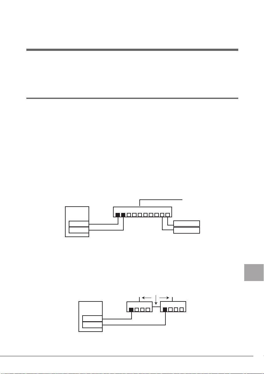
・ AFT/ALB の構成
PRIMERGY
スイッチ
(*)
、自動的にもう一方の経路
PG-1892
PG-1892
Primary link
Secondary link
クライアン
クライアン
■ SFT
SFT(スイッチ フォルト トレランス)とは、LAN ポートが別々のスイッチに接続された
構成での二重化機能です。スイッチは、二重化された構成で使用できます。LAN ポート
と、そのポートが接続されているスイッチとの間に異常
路を切り替えます。しかし、スイッチとスイッチの間(次の図←、↓、→)のエラーは検
出できません。
・ SFT の構成
PRIMERGY
スイッチ
PG-1892
PG-1892
Primary link
Secondary link
(*)
が発生したとき、使用する経
スイッチ
5 チーム化 (AFT/ALB/SFT/ 静的リンク) 21
J
Page 22

*)LAN ポートとスイッチ間のリンク断と 同等の異常のみ検出します。したがって、ス
ト
ト
イッチが部分的に故障しても、LAN ポートが接続されているポートがリンクレベルで
正常な場合は、経路の切り替えは発生しません。
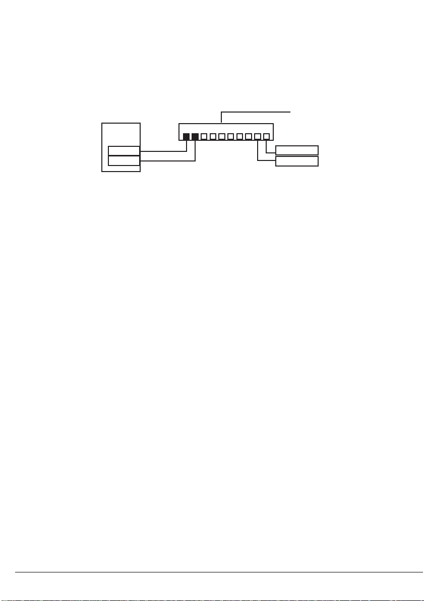
■ 静的リンク
静的リンク アグリゲーション(以下、静的リンク)とは、AFT の二重化機能に加え、
LAN ポートをチームに追加することにより、スループットを向上させることが出来る機能
です。各チームメンバーの送信のロードを継続的に分析し、スイッチ ロードは受信トラ
フィックを調整します。すべてのアダプタは同じ速度で稼動する必要があり、チーム内の
ポートはすべて同一スイッチに接続されている必要があります。また、リンクアグリゲー
ションに対応するスイッチ(PA gP プロトコル使用の Cisco の FEC または GEC に対応した
スイッチ、リンク集計可能な Intel Express(R) スイッチ、静的 802.3ad 対応の他のスイッチ)
と併用する必要があります。
・ 静的リンクの構成
PRIMERGY
スイッチ
PG-1892
PG-1892
Primary link
Secondary link
クライアン
クライアン
■ 注意事項
本ドライバでチーム化を使用する場合の注意事項を次に示します。詳細については、
®
「Intel
PROSet 」の説明文を参照してください。ただし、説明文の内容と本書の内容が異
なる場合は、本書の内容を優先してください。
・ チーム化は Windows Server 2003/Windows 2000 Server(SP4 以降必須)に限り使用できま
す。
・ チームを構成すると、OS 上に仮想アダプタ(例:Intel(R) Advanced Network Services
Virtual Adapter など)が作成されます。上位プロトコルは、チームを構成している個々
の実アダプタではなく、この仮想アダプタにバインドされます。
・ AFT/ALB/ 静的リンクのチームの構成 1 組に使用可能な LAN のポートは、最大 4 ポート
です。
また、同一システムでは最大 2 組までのチームを構成することができます。なお、使用
できる LAN のポート数は、システムごとに制限がありますのでご注意ください。
・ SFT 1 組に使用可能な LAN のポートは、最大 2 ポートです。また、同一システムでは最
大 2 組までのチームを構成できます。
・ Gigabit Ethernet のポートと Fast Ethernet のポートを混在させて AFT/ALB/SFT を構成する
こともできます。
・ チーム化使用時は、IPSec のハードアシスト機能は使用できません。チーム内のすべて
の LAN ポートが、IPSec のハードアシスト機能を持っていても使用しないでください。
・ AFT/ALB/SFT/ 静的リンク使用時は、次の対象プロトコルに限り使用できます。
- AFT/SFT/ 静的リンク:IP、NetBEUI、IPX(NCP)、IPX(NetBIOS)
-ALB:IP、IPX(NCP)
・ チーム内の LAN ポートは、同一ネットワーク(ブロードキャストドメイン)に存在す
る必要があります。また、IP アドレスは共有します。
・ ALB 使用時は、スイッチングハブに限り使用できます。
22
Page 23

・ チーム化使用時は、Windows Load Balancing Service(WLBS)や NLB(Network Load
Balancing)を使用することはできません。
・ PG-1852 ではチームを構成できません。
・ 静的リンク使用時は、リンクアグリゲーションに対応するスイッチのみ使用可能です。
・ AFT/ALB/ 静的リンク使用時は、同一のスイッチに接続する必要があります。
・ SFT 使用時は、スイッチ側のスパニングツリー機能が活性化(オン)にする必要があり
ます。
・ AFT/ALB/ 静的リンク使用時は、スイッチ側に接続されているポートのスパニングツ
リー機能を非活性化(オフ)にする必要があります。
・ 静的リンクのチームに LAN カードを追加/削除などをするときは、リンクがダウンし
ている状態で行う必要があります。
・ 静的リンクは、すべてのアダプタが同じ速度で稼動する必要があります。
・ チーム化オプションで、高速チームは使用しないでください。
・ オンボード LAN を RemoteControlService による遠隔操作を行う場合は、オンボード
LAN をチームのメンバーに使用できません。
RemoteControlService の詳細は、「ServerView ユーザーズガイド」を参照してください。
・ オンボード LAN の RemoteControlService を行う設定をして、オンボード LAN でチーム
化を行った場合、RemoteControlService による遠隔操作が正しく機能しません。
®
・ Intel
PROSet による Broadcom のオンボード LAN と Intel の LAN カードによるチーム作
成が可能です。チーム作成時の注意点は、次のとおりです。
®
-Intel
PROSet では、Broadcom のオンボード LAN だけでチームを構成することはでき
ません。
®
PROSet で Broadcom のオンボード LAN をチーム化する場合、チーム化に必ず
-Intel
Intel の LAN ポートを 1 ポート以上組み込む必要があります。
®
-Intel
PROSet でチームに組み込むことができない Broadcom のオンボード LAN の対
象機種は、次のとおりです。
・ PRIMERGY RX300 / PRIMERGY TX200
- チーム作成時には、Intel の LAN カードの優先度を必ず「1 次(プライマリ)」に設定
してください(「設定」タブから「チームの編集」をクリックしてください)。
5 チーム化 (AFT/ALB/SFT/ 静的リンク) 23
J
Page 24

5.2 チームの作成
チームを作成する場合は、次の手順で行います。
1 管理者権限でログオンします。
2 デバイスマネージャでチームを作成する LAN アダプタをダブルクリック
し、Intel
→「■ Intel® PROSet の起動方法」(P. 1 6)
®
PROSet を起動します。
3 [チーム化]タブをクリックします。
4 「その他のアダプタとチーム化する」を選択し、[新規チーム]をクリック
します。
「新規チームの作成ウィザード」 が表示されます。
5 任意のチーム名を入力し、[次へ]をクリックします。
6 チームに組み込む LAN アダプタのみを選択し、[次へ]をクリックしま
す。
「チームモードの選択」が表示されます。
7 作成するチームのタイプを選択し、[次へ]をクリックします。
・ AFT 使用時:「アダプタ フォルト トレランス」
・ ALB 使用時:「アダプティブ ロード バランシング」
・ SFT 使用時:「スイッチ フォルト トレランス」
・ 静的リンク使用時:「静的リンク アグリゲーション」
上記以外のチームのタイプを選択しないでください。
` オンボード LAN を RemoteControlService による遠隔操作を行う場合には、オン
ボード LAN のチェックを外してください(オンボード LAN はチームに組み込め
ません)。
` 次のようなダイアログが表示された場合で、オンボード LAN を
RemoteControlService による遠隔操作を行う場合は、[いいえ]をクリックし、
オンボード LAN のチェックを外してください。RemoteControlService による遠
隔操作を行わない場合には、[はい]をクリックしてください。
24
8 [完了]をクリックします。
作成したチームのプロパティ画面が表示されます。
Page 25

9 [OK]をクリックして、チームのプロパティ画面を閉じます。
LAN アダプタのプロパティ画面が表示されます。
ただし、「このチームには、インテル以外のアダプタが含まれているのでジャンボ
フレームをサポートしません。」が表示された場合は、[はい]をクリックしてくだ
さい。
10 [OK]をクリックし、LAN アダプタのプロパティ画面を閉じます。
11 システムを再起動します。
作成したチーム(仮想アダプタ)のドライババージョンのバージョンレベルを、「1.2 モ
ジュールのバージョンレベル」(→ P. 8 )を参照して確認してください。
チーム化の設定が完了すると、次の仮想アダプタが作成されます。
TEAM:(チーム名)
上位プロトコルは、本仮想アダプタにバインドされます。
チームを構成する LAN カードには、バインドできません。
IP アドレスは、本仮想アダプタに設定できます。
5.3 チームの削除
チームを削除する場合は、次の手順で行います。
1 管理者権限でログオンします。
2 デバイスマネージャでチームを削除する仮想アダプタをダブルクリック
し、Intel
→「■ Intel® PROSet の起動方法」(P. 16 )
削除するチームの仮想アダプタが開きます。
®
PROSet を起動します。
3 [設定]タブをクリックします。
4 「チームの削除」をクリックします。
確認メッセージが表示されます。
5 [はい]をクリックします。
6 システムを再起動します。
` 仮想アダプタを、「デバイス マネージャ」や「ネットワークとダイアルアップ接
続」、「ネットワーク接続」から無効化や削除を行わないでください。この仮想アダ
プタを削除する場合は、必ず 「Intel
®
PROSet」をご使用ください。
5 チーム化 (AFT/ALB/SFT/ 静的リンク) 25
J
Page 26

5.4 イベントログ
AFT / ALB / SFT /静的リンク使用時は、次のイベントログが発生します(ソース:i
ANSMiniport)。
ID
種別 メッセージ
6
情報 プライマリ アダプタが初期化されました:(アダプタ名)
7
情報 アダプタが初期化されました:(アダプタ名)
8
情報 (チーム名):チームが初期化されました。
10
情報 現在のプライマリ アダプタが次のアダプタから切り替わります:
(アダプタ名)
11
警告 次のアダプタ リンクは接続されていません:(アダプタ名)
12
情報 セカンダリ アダプタが優先します:(アダプタ名)
13
警告 (アダプタ名) がチームで無効化されました。
14
情報 セカンダリ アダプタがチームに再び追加されました:(アダプタ名)
15
情報 次のアダプタのリンクが接続されています:(アダプタ名)
16
警告 (チーム名):最後のアダプタはリンクを失いました。ネットワーク
接続が失われました。
17
情報 (チーム名):アダプタはリンクを再確立しました。ネットワークの
接続が復元されました。
18
情報 次の優先プライマリ アダプタが検出されました:(アダプタ名)
19
情報 次の優先セカンダリ アダプタが検出されました:(アダプタ名)
20
情報 次の優先プライマリ アダプタが優先されます:(アダプタ名)
21
情報 次の優先セカンダリ アダプタが優先されます:(アダプタ名)
22
警告 プライマリ アダプタは次のブローブを検出できませんでした:
(アダプタ名) 原因:チームが分割されている可能性があります。
35
警告 1 アダプタの欠落している(チーム名)を初期化しています。すべて
のアダプタが存在していることを確認してください。
38
情報 チームから(アダプタ名)が削除されました。
42
警告 (アダプタ名)が正しく設定されていません。
アダプタは、リモート管理機能を処理すると同時にネットワーク
チームであることはできません。
26
■ 注意事項
・ チーム化が正しく動作を開始した場合でも、システム起動時に、ID = 6、7、8 のイベン
トログが格納されますが、問題ありませんので無視してください。
・ チーム化を構成すると、システム起動時にイベントビューアのシステムログに ID = 11、
13、22 の警告ログと ID = 15 などのイベントログが複数格納される場合がありますが、
問題ありませんので無視してください。
・ オンボード LAN でリモート管理機能を使用していない場合も、ID=42 のイベントログ
が格納されます。リモート管理機能を使用していない場合は問題ありませんので本メッ
セージは無視してください。
Page 27

6
VLAN
この章では、VLAN について説明しています。
6.1 VLAN について
バーチャル LAN(VLAN)とは、LAN に接続される装置を、物理的な接続形態ではなく論
理的にグループ化したものです。VLAN は、装置が使用できるネットワークセグメントを
特定することができます。これにより、ネットワークの性能とセキュリィティ向上が図ら
れます。
また、VLAN は、複数のユーザや装置を論理的にグル-プ化する機能があるため、建物間
のネットワーク管理を容易にすることができます。
通常 VLAN とは、スイッチ側の設定によるもので、装置は、1 つの LAN カードごとに 1
つの VLAN にしか属することができません。しかし、本ドライバを使用すると、1つの
LAN カード上に複数の VLAN を構成することが可能です。
本ドライバは、 IEEE802.1Q で定義された VLAN をサポートします。
PRIMERGY
Client
Client
スイッチ
(IEEE802.1Qサポート)
Client
Client
VLAN30VLAN20VLAN10
Client
Client
VLAN10、20、30
PG-1892
■ 留意事項
本ドライバで VLAN を使用する場合の注意事項を次に示します。詳細については、「Intel®
PROSet」の説明文を参照してください。なお、説明文の内容と本書の内容が異なる場合
は、本書の内容を優先してください。
・ VLAN は、Windows Server 2003/Windows 2000 Server(SP4 以降必須)でのみ使用できま
す。
・ Broadcom のオンボード LAN および Broadcom のオンボード LAN を含むチームのアダプ
タには、VLAN を設定できません。
・ VLAN 上では IP 以外のプロトコルを使用しないでください。
富士通通信制御サービスで、LLC、LNDFC プロトコルをインストールすると、VLAN
とこれらのプロトコルは、無条件にバインド(接続)されてしまいます。したがって、
IP 以外のプロトコルが、VLAN と同時にインストールされたシステムでは、VLAN とそ
れらのプロトコルのバインドを解除してください。
・ 1 つの LAN ポートに設定可能な VLAN の個数は最大 10 本です。
J
6 VLAN 27
Page 28

・ Windows Server 2003/Windows 2000 Server で、NetBIOS over TCP/IP が有効な VLAN は、
システム全体で最大 4 本にしてください。
6.2 VLAN の作成
VLAN を作成する場合は、次の手順で行います。
1 LAN ポートを接続するスイッチのポートを、VLAN のタグフレームを送
受信できるように設定します。
2 管理者権限でログオンします。
3 デバイスマネージャで VLAN を構成する LAN アダプタをダブルクリック
し、Intel
→「■ Intel® PROSet の起動方法」(P. 1 6)
®
PROSet を起動します。
4 [VLAN]タブをクリックします。
チーム化を構成しているアダプタに VLAN を設定できません。
5 [新規作成]をクリックします。
6 「VLAN ID」 と「VLAN 名」を設定して、[OK]をクリックします。
「VLAN ID」は、スイッチ側の設定値と一致している必要があります。設定可能な
範囲は、1 ~ 4094 です。
「VLAN 名」は、スイッチ側の設定と一致している必要はありません。
7 [OK]をクリックし、LAN アダプタのプロパティ画面を閉じます。
8 システムを再起動します。
作成した VLAN(仮想アダプタ)のドライババージョンのバージョンレベルを、「1.2 モ
ジュールのバージョンレベル」(→ P. 8 )を参照して確認してください。
VLAN の設定が完了すると、次の仮想アダプタが作成されます。
(LAN アダプタ名)- VLAN:(VLAN 名)
上位プロトコルは、本仮想アダプタにバインドされます。
VLAN を構成する LAN カードにはバインドできません。
IP アドレスは、本仮想アダプタに設定します。
28
Page 29

6.3 VLAN の削除
VLAN を削除する場合は、次の手順で行います。
1 管理者権限でログオンします。
2 デバイスマネージャで VLAN を削除する仮想アダプタをダブルクリック
し、Intel
→「■ Intel® PROSet の起動方法」(P. 16 )
削除する VLAN の仮想アダプタが開きます。
®
PROSet を起動します。
3 [設定]タブをクリックします。
4 「VLAN の削除」をクリックします。
確認メッセージが表示されます。
5 [OK]をクリックします。
6 システムを再起動します。
` 仮想アダプタを、「デバイス マネージャ」や「ネットワーク接続」から無効化や削
除を行わないでください。この仮想アダプタを削除する場合は、必ず 「Intel
PROSet」をご使用ください。また、一度 VLAN を削除したあと再度 VLAN を追加
する場合は、システムを再起動したあとに、VLAN を追加してください。
®
6 VLAN 29
J
Page 30

7
カードをネットワークに接続できな い場合の解決方法
この章では、LAN カードをネットワークに接続できない場合について説明してい
ます。
LAN カードが正常な場合は、LED の状態は表のとおりです。
LED が点灯、点滅しないときは、次のことが考えられますので、確認してください。
・ PG-1862 / 286 の場合
LED の種類 LED の状態 LAN カードの状態
○ ACT/LNK A、
ACT/LNK B
○ 10=OFF
100=GRN
1000=ORG
- ACT/LNK A/B LED が点灯/点滅しない場合
・ ドライバがインストールされているかを確認してください。
・ スイッチ、ハブとの接続を確認してください。
・ スイッチ、ハブの別ポートを使用してください。
・ ネットワークが無通信状態の可能性があります。通信相手からのログイ
ンを試してください。
・ PG-1882(L) の場合
LED
○ ACT/LNK
-ACT/LNK LEDが点灯/点滅しない場合
・ ドライバがインストールされているかを確認してください。
・ スイッチ、ハブとの接続を確認してください。
・ スイッチ、ハブの別ポートを使用してください。
・ ネットワークが無通信状態の可能性があります。通信相手からのログイ
ンを試してください。
点灯(緑色) スイッチ、ハブとのリンクが正しく確立されている。
点滅(緑色) データ送受信中。
点灯(オレンジ色) カードが、通信速度 1000Mbps で動作している。
点灯(緑色) カードが、通信速度 100Mbps で動作している。
消灯 カードが、通信速度 10Mbps で動作している。
点滅(オレンジ色)
LED の状態 LAN カードの状態
点灯(緑色) スイッチ、ハブとのリンクが正しく確立されている。
点滅(緑色) データ送受信中。
点滅(オレンジ色)
®
「Intel
PROSet」の「アダプタを識別」でカードを点
滅させている。
®
「Intel
PROSet」の「アダプタを識別」でカードを点
滅させている。
ACT/LNK A
ACT/LNK B
10=OFF
100=GRN
1000=ORG
ACT/LNK
30
Page 31

・ PG-1892(L) の場合
LED
○ ACT/LNK
○ 10=OFF
100=GRN
1000=ORG
LED の状態 LAN カードの状態
(緑色) スイッチ、ハブとのリンクが正しく確立されている。
点灯
点滅(緑色) データ送受信中。
点灯(オレンジ色)
点灯(緑色)
消灯
点滅(オレンジ色) 「Intel
カードが、通信速度 1000Mbps で動作している。
カードが、通信速度 100Mbps で動作している。
カードが、通信速度 10Mbps で動作している。
®
PROSet」の「アダプタを識別」でカードを点
滅させている。
-ACT/LNK LEDが点灯/点滅しない場合
・ ドライバがインストールされているかを確認してください。
・ スイッチ、ハブとの接続を確認してください。
・ スイッチ、ハブの別ポートを使用してください。
・ ネットワークが無通信状態の可能性があります。通信相手からのログ
インを試してください。
・ PG-2861(L) の場合
LED の種類 LED の状態 LAN カードの状態
○ ACT/LNK A、
ACT/LNK B
○ 10=OFF
100=GRN
1000=ORG
点灯(緑色) スイッチ、ハブとのリンクが正しく確立されている。
点滅(緑色) データ送受信中。
点灯(オレンジ色) カードが、通信速度 1000Mbps で動作している。
点灯(緑色) カードが、通信速度 100Mbps で動作している。
消灯 カードが、通信速度 10Mbps で動作している。
点滅(緑色)
®
「Intel
PROSet」の「アダプタを識別」でカードを点
滅させている。
- ACT/LNK A/B LED が点灯/点滅しない場合
・ ドライバがインストールされているかを確認してください。
・ スイッチ、ハブとの接続を確認してください。
・ スイッチ、ハブの別ポートを使用してください。
・ ネットワークが無通信状態の可能性があります。通信相手からのログイ
ンを試してください。
ACT/LNK
10=OFF
100=GRN
1000=ORG
ACT/LNK A
ACT/LNK B
10=OFF
100=GRN
1000=ORG
7 カードをネットワークに接続できない場合の解決方法 31
J
Page 32

8
LAN カードの仕様
この章では、本ドライバを添付する LAN カードの仕様を説明します。
型名
規格
IEEE802.3u(100BASE-TX)●-●●●
IEEE802.3z(1000BASE-SX)-●---
IEEE802.3ab(1000BASE-T)●-●●●
IEEE802.3i(10BASE-T)●-●●●
ネットワーク種類(伝送速度)
10BASE-T(10Mbps) ●-●●●
100BASE-TX(100Mbps)●-●●●
1000BASE-SX(1000Mbps)-●---
1000BASE-T(1000Mbps)●-●●●
PCI 規格
PCI2.2:32bit33MHz ●●●--
PCI2.2:64bit33MHz ●●●--
PCI2.2:64bit66MHz ●●●--
PCI-X 1.0a:64bit100MHz ●●●--
PCI-X 1.0a:64bit133MHz ●●●--
PCI-Express 1.0a
LAN コントローラ
®
Intel
82545GM
®
Intel
82546EB
®
Intel
82546GB
®
Intel
82571GB
ポート数
1 ポート -●●--
2 ポート ●--●●
コネクタ
RJ-45
LC
ケーブル(別売)
カテゴリ 5/ カテゴリ 5e ●-●●●
マルチモードファイバー - ● - - -
*:LAN カード経由での電源制御はできません。
PG-1862 PG-1882(L) PG-1892(L) PG-286 PG-2861(L)
---●●
-●●--
●----
---●-
----●
●-●●●
-●---
32
Page 33

付録
A
A.1 ローカルアドレスの設定
ローカルアドレスを設定する場合は、次の手順で行います。
1 管理者権限でログオンします。
2 デバイスマネージャーで使用する LAN アダプタをダブルクリックし、
3 [詳細設定]タブをクリックします。
4 「ローカル管理されるアドレス」の値に設定するローカルアドレスを設定
5 [OK]をクリックします。
6 システムを再起動します。
®
Intel
PROSet を起動します。
→「■ Intel® PROSet の起動方法」(P. 16 )
します。
12 桁の 16 進数を入力してください。
` グローバルアドレスに戻したい場合は、「存在しない」にチェックを入れるか、
「ローカル管理されるアドレス」の値を削除してください。
A.2 通信速度/デュプレックスモードの設定
LAN カードは、通信速度とデュプレックスモードのオートネゴシエーション(自動認識)
機能を備えています。通常、スイッチ等の接続装置も同様に自動認識機能を備えている場
合は、自動的に最適な通信速度、デュプレックスモードを選択して動作します。
通信速度/デュプレックスモードを設定する場合は、次の手順で行います。
■ 100 BASE-TX LAN カード(PG-1851/1861/1871(L))の場合
接続装置が自動認識機能を備えていない場合などに、固定的に通信速度とデュプレックス
モードを設定する必要がある場合は、次の方法で設定してください。
J
1 管理者権限でログオンします。
2 デバイスマネージャーで使用する LAN アダプタをダブルクリックし、
®
Intel
PROSet を起動します。
→「■ Intel® PROSet の起動方法」(P. 16 )
付録 A 33
Page 34

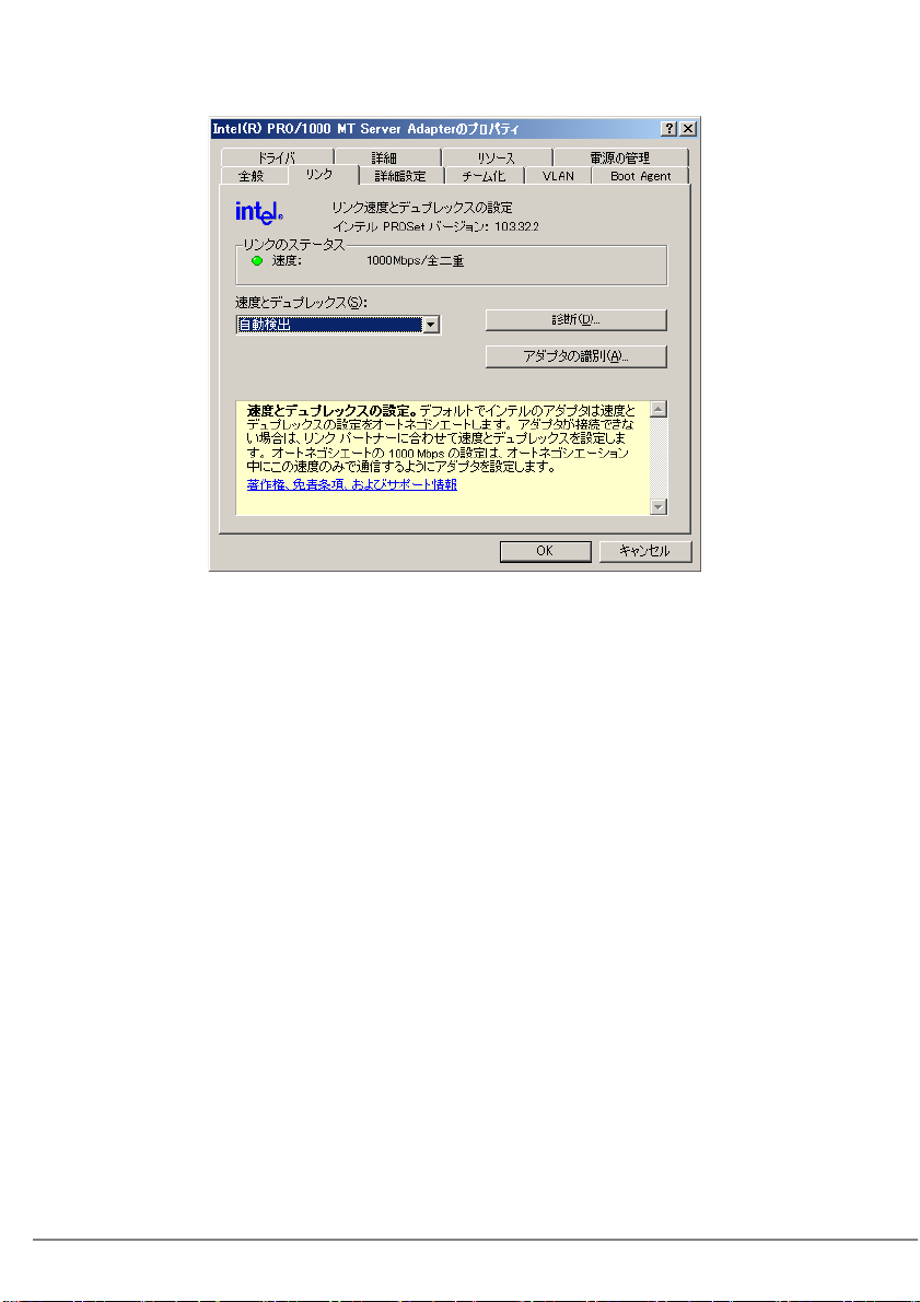
3 [リンク]タブをクリックします。
4 「速度とデュプレックス設定」で使用する通信速度とデュプレックスモー
ドを設定します。
5 [OK]をクリックします。
6 システムを再起動します。
` 固定的に全二重モードに設定する場合は、必ず LAN カードと接続装置の両方を設定してく
ださい。
■ 1000 BASE-T LAN カード(PG-1852/1862/1891(L)/1892(L)/286/
2861(L))の場合
固定的に 1000Mbps の速度に設定することができず、接続装置が 1000Mbps で通信可能な
場合は、デフォルトの設定(オートネゴシエーション = 有効)で、通常 1000Mbps の通信
を行います。
固定的に通信速度とデュプレックスモードの設定が必要な場合は、次の方法で行ってくだ
さい。なお、この場合は 100Mbps 以下の速度しか指定できません。
1 管理者権限でログオンします。
2 デバイスマネージャーで使用する LAN アダプタをダブルクリックし、
®
Intel
PROSet を起動します。
→「■ Intel® PROSet の起動方法」(P. 1 6)
3 [リンク]タブをクリックします。
4 「速度とデュプレックス設定」で使用する通信速度とデュプレックスモー
ドを設定します。
5 [OK]をクリックします。
6 システムを再起動します。
` 固定的に全二重モードに設定する場合は、必ず LAN カード/接続装置の両方を設定してく
ださい。
34
Page 35

A.3 ジャンボフレームについて
Gigabit Ethernet では、ジャンボフレームが使用できます。ジャンボフレームを使用する際
は、ジャンボフレームネットワーク内の機器は、すべてジャンボフレーム対応装置で構成
し、ジャンボフレームを有効にする設定をしてください。
1 管理者権限でログオンします。
2 デバイスマネージャーで使用する LAN アダプタをダブルクリックし、
®
Intel
PROSet を起動します。
→「■ Intel® PROSet の起動方法」(P. 16 )
3 [詳細設定]タブをクリックします。
4 「ジャンボ フレーム」に使用する値に設定します。
5 [OK]をクリックします。
6 システムを再起動します。
付録 A 35
J
Page 36

A.4 LAN カードの筐体外部からの特定について
LAN カードがシステムに複数搭載されていても、「Intel® PROSet」の LAN カードの LED
を点滅させる機能を利用して、特定の MAC アドレスを持つ LAN カードを本体装置外部か
ら容易に判別できます。
` オンボード LAN の場合、LED は点滅しません。
判別方法は、次のとおりです。
1 管理者権限でログオンします。
2 デバイスマネージャーで使用する LAN アダプタをダブルクリックし、
®
Intel
PROSet を起動します。
→「■ Intel® PROSet の起動方法」(P. 1 6)
3 [リンク]タブをクリックします。
4 [アダプタの識別]をクリックします。
「恒久イーサネット アドレス」が 、LAN カードの MAC アドレスです。
5 [開始]をクリックします。
該当する LAN カードの LED が点滅します。
` 初期画面にあるイーサーネットアドレスにも、通常そのカードの MAC アドレスが表
示されますが、チーム化を構成しているカードがセカンダリ側に使用されている場
合は、プライマリ側に使用されている LAN カードの MAC アドレスが表示されま
す。
36
Page 37

A.5 チーム化を構成するカードの交換手順について
チーム化を構成している LAN カードを交換する場合は、次の手順で行います。
1 システムの電源を切断後、LAN カードを交換します。
2 システムを再起動します。
3 管理者権限でログオンします。
4 起動されているアプリケーションがあれば、すべて終了させます。
5 デバイスマネージャーで使用する LAN アダプタをダブルクリックし、
®
Intel
PROSet を起動します。
→「■ Intel® PROSet の起動方法」(P. 16 )
6 交換した LAN アダプタが含まれるチームの仮想アダプタのプロパティを
開きます。
7 [設定]タブをクリックします。
8 「チームの編集」を選択します。
「チームの編集」画面が表示されます。
確認メッセージが表示される場合は、[OK]をクリックし、続行してください。
・ 優先度を設定している場合は、次の作業を行ってください。
1. アダプタを選択して[優先度の削除]をクリックします。
2. [OK]をクリックして、「チームの編集」画面を閉じます。
3. [チームの編集]をクリックします。
4. 元の優先度設定と同じ設定をします。
5. [OK]をクリックして、「チームの編集」画面を閉じます。
6. [OK]をクリックして、「チームのプロパティ」画面を閉じます。
・ 優先度を設定していない場合は、次の作業を行ってください。
1. 任意のアダプタを選択して、[プライマリの設定]をクリックします。
2. [OK]をクリックして、「チームの編集」画面を閉じます。
3. [チームの編集]をクリックします。
4. 優先度を設定しているアダプタを選択して、[優先度の削除]をクリックしま
す。
5. [OK]をクリックして、「チームの編集」画面を閉じます。
6. [OK]をクリックして、「チームのプロパティ」画面を閉じます。
J
9 システムを再起動します。
付録 A 37
Page 38

` チーム化を構成する LAN カードを交換する場合、交換前の LAN カードがプライマリ
に設定されていると、LAN カード交換後も交換前の LAN カードの MAC アドレス
が交換後のカードに引き継がれて使用されます。そのため、交換された LAN カー
ドが、同一セグメントで再度使用されると、MAC アドレスの衝突が発生してしま
います。チームで使用中の LAN カードを交換する場合は、「A.5 チーム化を構成す
るカードの交換手順について」(→ P. 3 7 )でドライバを再設定することが必要です。
` 交換する LAN カードを、交換前の LAN カードとは別のスロット位置に搭載する場合
は、ドライバの削除と再インストールが必要です。
38
Page 39

Before Reading This Manual
Thank you for purchasing the PRIMERGY LAN card.
The card can be installed to the PCI slot of the PC server "PRIMERGY" to configure Local Area
Network (LAN) system.
This manual explains LAN cards and the LAN driver (for Windows Server 2003 and Windows 2000
Server). Read this manual carefully to handle the product correctly.
For details about drivers for other operating systems, refer to manuals supplied with the system or the
Fujitsu PRIMERGY website:
(http://primergy.fujitsu.com)
For Your Safety
This manual contains important information, required to operate this product safely.
Thoroughly review the information in this manual before using this product. Especially note the points under "Safety",
and only operate this product with a complete understanding of the material provided.
This manual should be kept in an easy-to-access location for quick reference when using this product.
High Safety
The Products are designed, developed and manufactured as contemplated or general use, including without limitation,
general office use, personal use, household use, and ordinary industrial use, but are not designed, developed and
manufactured as contemplated for use accompanying fatal risks or dangers that, unless extremely high safety is secured,
could lead directly to death, personal injury, severe physical damage, or other loss (hereinafter "High Safety Required
Use"), including without limitation, nuclear reaction control in nuclear facility, aircraft flight control, air traffic control,
mass transport control, medical life support system, missile launch control in weapon system. You shall not use this
Product without securing the sufficient safety required for the High Safety Required Use. If you wish to use this Product
for High Safety Required Use, please consult with our sales representatives in charge before such use.
June 2006
39
E
Page 40

Remarks
Warning Descriptions
Various symbols are used throughout this manual. These are provided to emphasize important points
for your safety and that of others. The symbols and their meanings are as follows. Be sure to fully
understand these before reading this manual.
WARNING
CAUTION
The following symbols are used to indicate the type of warning or cautions being described.
Ignoring this symbol could be potentially lethal.
Ignoring this symbol may lead to injury and/or damage the device or internal
options.
A triangle mark emphasizes the urgency of the WARNING and CAUTION.
Details are described next to the triangle.
A barred circle ( ) warns against certain actions (Do Not). Details are
described next to the circle.
A black circle indicates actions that must be taken.
Details are described next to the black circle.
Symbols
The following are symbols used throughout this manual.
Symbols Meaning
These sections explain prohibited actions and points to note when using this
device. Make sure to read these sections.
These sections explain information needed to operate the hardware and
software properly. Make sure to read these sections.
→ This mark indicates reference pages or manuals.
Key Descriptions / Operations
Keys are represented throughout this manual in the following manner.
E.g.: [Ctrl] key, [Enter] key, [→] key, etc.
The following indicate pressing several keys at once.
E.g.: [Ctrl] + [F3] key, [Shift] + [↑] key, etc.
Entering Commands (Keys)
CD-ROM drive names are shown as [CD-ROM drive]. Enter your drive name according to your
environment.
[CD-ROM drive]:\setup.exe
40
Page 41

Abbreviations
The following expressions and abbreviations are used to describe the product names used in this
manual.
Product names
Microsoft
Microsoft
Microsoft
Microsoft
Microsoft
Microsoft
Microsoft
Microsoft
Microsoft
Itanium-Based Systems
Microsoft
Microsoft
Onboard/PG-18xx/PG-28xx LAN Driver V10.3 This driver or the driver
®
Windows Server™ 2003, Standard Edition Windows Server 2003
®
Windows Server™ 2003, Enterprise Edition
®
Windows Server™ 2003 R2, Standard Edition
®
Windows Server™ 2003 R2, Enterprise Edition
®
Windows Server™ 2003, Standard x64 Edition Windows Server 2003
®
Windows Server™ 2003, Enterprise x64 Edition
®
Windows Server™ 2003 R2, Standard x64 Edition
®
Windows Server™ 2003 R2, Enterprise x64 Edition
®
Windows Server™ 2003, Enterprise Edition for
®
Windows® 2000 Server
®
Windows® 2000 Advanced Server
Expressions and
abbreviations
or Windows Server 2003
IA32
or Windows Server 2003
x64
Windows Server 2003
or Windows Server 2003
IA64
Windows 2000 Server
Safety
For your safety and that of others, follow the guidelines provided on the following pages concerning
the use of this product.
WARNING
• Do not tinker with the product. Doing so may cause a fire or electric shock.
• Keep the product away from water. Failure to do so may cause a fire or electric
shock.
• When there is lightning nearby, unplug all power cords and external connecting
cords from the card. Failure to do so may cause damage to the devices or a fire.
CAUTION
• Since the card is delicate, avoid using or storing it under extreme conditions,
such as excessively high or low temperature, high humidity, or in direct sunlight.
Do not bend or damage the card or subject it to extreme shock. Doing so may
cause failure or fire.
• While not in use, store the card in the bag in which it was packaged to protect it
from static electricity.
E
41
Page 42

Check the items supplied
Before using the product, check that no supplied or attached items are missing.
If any items are missing, contact an office listed in "Appendix B Contact Information" (
• LAN Card
• Driver CD
• LAN Driver V10.3 User ’s Guide (this manual)
Jpg.74).
42
Intel is a registered trademark of Intel Corporation in the USA.
Microsoft, Windows, and Windows Server are trademarks or registered trademarks of Microsoft
Corporation in the USA and other countries.
Other product names used are trademarks or registered trademarks of their respective manufacturers.
Other products are copyrights of their respective manufacturers.
All Rights Reserved, Copyright© FUJITSU LIMITED 2006
Page 43

Contents
1 LAN Driver . . . . . . . . . . . . . . . . . . . . . . . . . . . . . . . . . . . . . . . . 44
1.1 LAN Driver Overview . . . . . . . . . . . . . . . . . . . . . . . . . . . . . . . . . . . . . 44
1.2 Module Version Level . . . . . . . . . . . . . . . . . . . . . . . . . . . . . . . . . . . . 45
2 Windows Server 2003 LAN Driver . . . . . . . . . . . . . . . . . . . . . 47
2.1 Updating the Driver . . . . . . . . . . . . . . . . . . . . . . . . . . . . . . . . . . . . . . 47
2.2 Adding a Card . . . . . . . . . . . . . . . . . . . . . . . . . . . . . . . . . . . . . . . . . . 48
2.3 Removing the Driver . . . . . . . . . . . . . . . . . . . . . . . . . . . . . . . . . . . . . 49
2.4 Displayed LAN Card Names . . . . . . . . . . . . . . . . . . . . . . . . . . . . . . . 49
3 Windows 2000 Server LAN Driver . . . . . . . . . . . . . . . . . . . . . 50
3.1 Updating the Driver . . . . . . . . . . . . . . . . . . . . . . . . . . . . . . . . . . . . . . 50
3.2 Adding a Card . . . . . . . . . . . . . . . . . . . . . . . . . . . . . . . . . . . . . . . . . . 52
3.3 Removing the Driver . . . . . . . . . . . . . . . . . . . . . . . . . . . . . . . . . . . . . 52
4 Intel® PROSet . . . . . . . . . . . . . . . . . . . . . . . . . . . . . . . . . . . . . 53
4.1 Intel® PROSet . . . . . . . . . . . . . . . . . . . . . . . . . . . . . . . . . . . . . . . . . . 53
4.2 Installing . . . . . . . . . . . . . . . . . . . . . . . . . . . . . . . . . . . . . . . . . . . . . . . 53
4.3 Uninstalling . . . . . . . . . . . . . . . . . . . . . . . . . . . . . . . . . . . . . . . . . . . . . 55
4.4 LAN Card Test . . . . . . . . . . . . . . . . . . . . . . . . . . . . . . . . . . . . . . . . . . 56
5 Teaming (AFT/ALB/SFT/Static Link Aggregation) . . . . . . . . 57
5.1 Teaming (AFT/ALB/SFT/Static Link Aggregation) . . . . . . . . . . . . . . . 57
5.2 Creating Team . . . . . . . . . . . . . . . . . . . . . . . . . . . . . . . . . . . . . . . . . . 60
5.3 Removing a Team . . . . . . . . . . . . . . . . . . . . . . . . . . . . . . . . . . . . . . . 61
5.4 Event Log . . . . . . . . . . . . . . . . . . . . . . . . . . . . . . . . . . . . . . . . . . . . . . 62
6 VLAN . . . . . . . . . . . . . . . . . . . . . . . . . . . . . . . . . . . . . . . . . . . . . 63
6.1 VLAN . . . . . . . . . . . . . . . . . . . . . . . . . . . . . . . . . . . . . . . . . . . . . . . . . 63
6.2 Creating VLAN . . . . . . . . . . . . . . . . . . . . . . . . . . . . . . . . . . . . . . . . . . 64
6.3 Removing VLAN . . . . . . . . . . . . . . . . . . . . . . . . . . . . . . . . . . . . . . . . 65
7 Solutions When the Card Cannot be Connected to Network 66
8 LAN Card Specifications . . . . . . . . . . . . . . . . . . . . . . . . . . . . . 68
Appendix A . . . . . . . . . . . . . . . . . . . . . . . . . . . . . . . . . . . . . . . . 69
A.1 Setting Local Address . . . . . . . . . . . . . . . . . . . . . . . . . . . . . . . . . . . . . 69
A.2 Setting Transmission Speed/ Duplex Mode . . . . . . . . . . . . . . . . . . . . . 69
A.3 Jumbo Frame . . . . . . . . . . . . . . . . . . . . . . . . . . . . . . . . . . . . . . . . . . . . 71
A.4 Specifying LAN Card from Outside Cabinet . . . . . . . . . . . . . . . . . . . . . 71
A.5 Replacement Procedure for Cards that Configure Teams . . . . . . . . . . 72
Appendix B Contact Information . . . . . . . . . . . . . . . . . . . . . . . 74
E
43
Page 44

1
LAN Driver
This chapter explains LAN driver.
1.1 LAN Driver Overview
This driver can be used for Intel Fast Ethernet card/Gigabit Ethernet card, and the onboard LAN for
this server (
Available OS
This driver is available for the following OSes.
• Windows Server 2003
• Windows 2000 Server(SP4 or later)
Available LAN card
This driver supports the following LAN cards.
• PG-1851 / PG-1852
• PG-1861 / PG-1862
• PG-1871(L)
• PG-1881(L) / PG-1882(L)
• PG-1891(L) / PG-1892(L)
• PG-286 / PG-2861(L)
J"8 LAN Card Specifications"(pg.68)).
J"2 Windows Server 2003 LAN Driver"(pg.47)
J"3 Windows 2000 Server LAN Driver"(pg.50)
44
` When a newer driver is obtained, refer to the manual attached with the newer driver
or its help file. Especially, if using a driver (later version) that is newer than this driver
is instructed in User's Guide in Document & Tool CD supplied with the server, do not
use this driver on the server.
Page 45

1.2 Module Version Level
The module version levels of the driver are as follows.
LAN adapters include Fast Ethernet (100BASE-TX), Gigabit Ethernet (1000BASE-T/1000BASESX), and virtual adapter (AFT, VLAN, etc.).
• For Windows Server 2003 IA32
Card type Module version File name
Fast Ethernet 8.0.27.0 e100b325.sys
Gigabit Ethernet 8.6.17.0 e1000325.sys
Virtual adapter 9.2.6.0 ianswxp.sys
PG2861(L) 9.3.28.0 E1e5132.sys
• For Windows Server 2003 x64
Card type Module version File name
Gigabit Ethernet 8.6.17.0 e1G5132.sys
Virtual adapter 8.2.6.0 Iansw32e.sys
PG2861(L) 9.3.28.0 e1e5132e.sys
• Windows Server 2003 IA64
Card type Module version File name
Gigabit Ethernet 8.6.17.0 e1000645.sys
Virtual adapter 9.2.6.0 Iansw64.sys
• For Windows 2000 Server
Card type Module version File name
Fast Ethernet 8.0.27.0 e100b325.sys
Gigabit Ethernet 8.6.17.0 e1000325.sys
Virtual adapter 9.2.6.0 ianswxp.sys
PG2861(L) 9.3.28.0 E1e5032.sys
1 LAN Driver 45
E
Page 46

How to check version level
To check the version level, use Device Manager. Details are as follows.
1 Start the [Computer Management].
• For Windows Server 2003
Click [Start]
• For Windows 2000 Server
Click [Start]
→ [Administrative Tools] → [Computer Management].
→ [Programs] → [Administrative Tools] → [Computer Management].
2 Click [Device Manager].
3 Double-click the Network adapter to check.
4 Click the [Driver] tab.
Check the displayed version.
5 Click the [Driver Details].
Check the displayed driver file version (file name to check).
46
Page 47

2
Windows Server 2003 LAN Driver
This chapter explains Windows Server 2003 LAN driver.
2.1 Updating the Driver
Perform the following procedures to update the driver.
Remove the Intel
®
PROSet in old version in advance.
1 Log on with the administrator privileges.
2 Insert the attached driver CD.
3 Click [Start] → [Administrative Tools] → [Computer Management].
The [Computer Management] window appears.
4 Click [Device Manager].
5 Click [Network adapters].
Installed LAN adapters are displayed.
• Intel PRO/100 *****
• Intel PRO/100+ *****
• Intel PRO/1000 *****
• Intel 82543GC-based *****
• Ethernet controller
Perform the following steps 6 - 10 for all LAN adapters.
` [Ethernet controller] may be displayed in [Other devices]. This driver is not
available for a port that uses a LAN controller other than Intel.
` A virtual adapter exists if AFT has been created, but do not select it.
` Install [Ethernet controller] after installation of other LAN adapters is
completed.
6 Double-click the icon of the LAN adapter.
Properties appears.
7 Click the [Driver] tab and click [Update Driver].
The [Hardware Update Wizard] window appears.
When the [Can Windows connect to windows Update to search for software?] message
appears, select [No, not this time] and click [Next].
8 Select [Install the software automatically (Recommended)] and
click [Next].
2 Windows Server 2003 LAN Driver 47
E
Page 48

9 Click [Finish].
` [This device cannot start. (Code 10)] may be displayed, but this is not a
problem since the system will operate normally after reboot. After pressing
[Finish], [Help and support center] appears. Click the [x] on the upper right
in the window.
10 Click [Close].
` Click [Advanced] tab, and change the value in [Adaptive Inter Frame Spacing] to
[On] if it is [Off].
11 Restart the system.
For LAN card names displayed in the [Device Manager] after the driver installation, refer to "2.4
Displayed LAN Card Names" (
Referring to "1.2 Module Version Level" (
adapters are correctly updated and that the version is correct.
` Do not set a small value in the [Receive Descriptors] in the LAN adapter properties.
Jpg.49).
Jpg.45), check that the drivers updated for all LAN
2.2 Adding a Card
48
When the system is started right after OS installation or new LAN card installation, the [Found NEW
Hardware] window may appear. The driver will be automatically installed.
However, when other driver than this driver is installed, refer to "2.1 Updating the Driver" (
to install a driver. For checking the version level, refer to "1.2 Module Version Level" (
When [Start new hardware search wizard] appears, click [Cancel] to close the window, and refer to
"2.1 Updating the Driver" (
Jpg.47) to install a driver.
Jpg.47)
Jpg.45).
Page 49

2.3 Removing the Driver
Perform the following procedures to remove the driver.
1 Log on with the administrator privileges.
2 Remove Intel
J"4.3 Uninstalling"(pg.55)
®
If "Intel
removed. In this case, steps 3 to 6 are not required.
To remove Intel
3 Click [Start] → [Settings] → [Control Panel] → [Add or Remove
Programs].
4 Select [Intel(R) PRO Network Connections Drivers] and click
[Change/Remove].
A confirmation message appears.
5 Click [Yes].
The driver is uninstalled.
6 Restart the system.
` If Intel® PRO Network Connections is removed, the LAN driver is removed together.
®
PROSet.
PRO Network Connections Software v10.3.32.2" is removed, all drivers are
®
PROSet in old version, select [Control Panel] - [Add/Remove Programs].
2.4 Displayed LAN Card Names
LAN card names displayed in [Device Manager] are as follows.
LAN Card LAN device name
PG-1851 Intel(R) PRO/100 Server Adapter
PG-1852 Intel(R) PRO/1000 MT Desktop Adapter
PG-1861 Intel(R) PRO/100 S Dual Port Server Adapter
PG-1862 Intel(R) PRO/1000 MT Dual Port Server Adapter
PG-1871(L) Intel(R) PRO/100 S Server Adapter
PG-1881(L) Intel(R) PRO/1000 XF Server Adapter
PG-1882(L) Intel(R) PRO/1000 MF Server Adapter
PG-1891(L) Intel(R) PRO/1000 XT Server Adapter
PG-1892(L) Intel(R) PRO/1000 MT Server Adapter
PG-286 Intel(R) PRO/1000 P Dual Port Server Adapter
PG-2861(L) Intel(R) PRO/1000 PT Dual Port Server Adapter
E
2 Windows Server 2003 LAN Driver 49
Page 50

3
Windows 2000 Server LAN Driver
This chapter explains Windows 2000 Server LAN driver.
3.1 Updating the Driver
Perform the following procedures to update the driver.
Remove the Intel
®
PROSet in old version in advance.
1 Log on with the administrator privileges.
2 Click [Start] → [Programs] → [Administrative Tools] → [Computer
Management].
The [Computer Management] window appears.
3 Click [Device Manager].
4 Double-click [Network adapters].
Installed LAN adapters are displayed.
• Intel PRO/100 *****
• Intel PRO/100+ *****
• Intel PRO/1000 *****
• Intel 82543GC-based *****
• Ethernet controller
Perform the following steps 6 - 13 for all LAN adapters.
` [Ethernet controller] may be displayed in [Other devices]. This driver is not
available for a port that uses a LAN controller other than Intel.
` A virtual adapter exists if AFT has been created, but do not select it.
5 Double-click the icon of LAN adapter.
Properties appears.
50
6 Click the [Driver] tab and click [Update Driver].
The [Welcome to the Upgrade Device Driver Wizard] window appears.
7 Click [Next].
The [Install Hardware Device Drivers] window appears.
8 Select [Search for a suitable driver for my device] and click [Next].
9 Insert the attached driver CD.
Page 51

10 Check the [CD-ROM drives] of the option in the searched place
only, and click [Next].
The [The wizard found a driver for the following device.] message appears.
11 Click [Next].
The [Finish device driver upgrade wizard] window appears.
12 Click [Finish].
13 Click [Close].
` Click [Advanced] tab, and change the value in [Adaptive Inter Frame Spacing] to
[On] if it is [Off].
14 Restart the system.
For LAN card names displayed in the [Device Manager] after the driver installation, refer to "2.4
Displayed LAN Card Names" (
Referring to "1.2 Module Version Level" (
adapters are correctly updated and that the version is correct.
` Do not set a small value in the [Receive Descriptors] in the LAN adapter properties.
Jpg.49).
Jpg.45), check that the drivers updated for all LAN
3 Windows 2000 Server LAN Driver 51
E
Page 52

3.2 Adding a Card
When the system is started right after OS installation or new LAN card installation, the following
window may appear. Follow the instructions below.
• When the [Found New Hardware] message appears:
When an OS-installed LAN card driver is newly added automatically, [Insert Disk] dialog box may
appear to request inserting [Intel(R) PRO Adapter CD-ROM or floppy disk] or [Intel(R) PRO/
1000 Driver Disk]. In this case, click [Cancel] and install the driver referring to "3.1 Updating the
Driver" (
Jpg.50).
• When [Welcome to the Found New Hardware Wizard] appears:
Click [Next] and go to step 8 in "3.1 Updating the Driver" (
step 13.
Jpg.50). It is not necessary to perform
3.3 Removing the Driver
Perform the following procedures to remove the driver.
1 Log on with the administrator privileges.
2 Remove Intel
J"4.3 Uninstalling"(pg.55)
®
If "Intel
removed. In this case, steps 3 to 6 are not required.
To remove Intel
3 Click [Start] → [Settings] → [Control Panel] → [Add or Remove
Programs].
®
PROSet.
PRO Network Connections Software v10.3.32.2" is removed, all drivers are
®
PROSet in old version, select [Control Panel] - [Add/Remove Programs].
52
4 Select [Intel(R) PRO Network Connections Drivers] and click
[Change/Remove].
A confirmation message appears.
5 Click [Yes].
The driver is uninstalled.
6 Restart the system.
` If Intel® PRO Network Connections is removed, the LAN driver is removed together.
Page 53

4
Intel® PROSet
This chapter explains Intel® PROSet.
4.1 Intel
Detailed settings of LAN card/driver are available using "Intel® PROSet". To operate Duplex mode/
Teaming/ VLAN setting or LAN card diagnosis, use [Intel
from [Control Panel] in the system.
How to Start Intel® PROSet
1
2 Click [Device Manager].
3 Double click the LAN adapter to be set.
` Simply installing this driver does not install [Intel® PROSet]. To install [Intel® PROSet], refer
to the followings.
• "4.2 Installing" (Jpg.53)
®
PROSet
Start the Computer Management.
• For Windows Server 2003
Click [Start]
• For Windows 2000 Server
Click [Start]
→ [Administrative Tools] → [Computer Management].
→ [Programs] → [Administrative Tools] → [Computer Management].
®
PROSet]. [Intel® PROSet] can be started
4.2 Installing
Perform the following procedures to install Intel® PROSet.
1. If team or VLAN is already configured, delete it.
2. If "Intel® PROSet Wired" is displayed in the [Control Panel], Intel® PROSet in old
version is installed. Uninstall the old version and install "Intel® PROSet" of this driver.
1 Log on with the administrator privileges.
2 Insert the attached driver CD.
4 Intel® PROSet 53
E
Page 54

3 Execute "DxSetup.exe" in the driver CD.
• For Windows 2000 Server/Windows Server 2003 IA32
[CD-ROM drive]:\APPS\PROSETDX\2KXPWS03\DxSetup.exe
• For Windows Server 2003 x64
[CD-ROM drive]:\APPS\PROSETDX\WS3XPx64\DxSetup.exe
• For Windows Server 2003 IA64
[CD-ROM drive]:\APPS\PROSETDX\WS03XP64\DxSetup.exe
[Intel(R) Pro Network Connections - InstallShield wizard] appears.
4 Click [Next].
5 Select [I accept the terms in the license agreement] and click
[Next].
[Setup type] appears.
6 Select [complete] and click [Next].
7 Click [Install].
Installing Intel® PROSet starts.
8 Click [Finish].
9 Restart the system.
For details on the settings of Intel® PROSet, see the explanation displayed at the bottom of the
®
PROSet" screen (in the yellow frame).
"Intel
54
Page 55

Clicking blue letters in the explanation displays the further detailed information.
- Do not set a small value in [Receive Descriptors] in [Advanced] of "Intel
- When descriptions in the explanation of "Intel
be given to this manual.
®
PROSet" and in this manual differ, priority shall
4.3 Uninstalling
Perform the following procedures to uninstall Intel® PROSet.
1 Log on with the administrator privileges.
2 Start [Add or Remove Programs] or [Add/Remove Programs].
®
PROSet".
` If team and VLAN are included, remove both of them using Intel
before uninstallation.
J"5.3 Removing a Team"(pg.61)
J"6.3 Removing VLAN"(pg.65)
• For Windows Server 2003
Click [Start]
• For Windows 2000 Server
Click [Start]
→ [Control Panel] → [Add or Remove Programs].
→ [Settings] → [Control Panel] → [Add/Remove Programs].
®
PROSet
3 Select [Intel(R) PRO Network Connections 10.3.32.2] and click
[Remove].
` If Intel® PROSet is removed, [Intel(R) PRO Network Connections software
v10.3.32.2] and the LAN driver are removed.
4 Click [Yes].
Intel® PROSet is uninstalled.
5 Restart the system.
4 Intel® PROSet 55
E
Page 56

4.4 LAN Card Test
Test method
Log on with the administrator privileges.
1
2 Double click the LAN adapter to be used by Device Manager and
start Intel
J" How to Start Intel® PROSet"(pg.53)
®
PROSet.
3 Click the [Link] tab.
4 Click [Diagnosis].
5 Select tabs to diagnose and click [Run Test] to test the LAN
adapter.
Actions to Take When an Error Occurs
If an error occurs when testing the LAN card, troubleshoot using the the procedure below.
• Check that the card is correctly installed in the PCI slot.
• Check the connecting environment of cables and switches.
If an error still occurs after the above actions, contact an office listed in "Appendix B Contact
Information" (
Jpg.74).
56
Page 57

5
Teaming (AFT/ALB/SFT/Static Link Aggregation)
This chapter explains Teaming (AFT/ALB/SFT/Static Link Aggregation).
5.1 Teaming (AFT/ALB/SFT/Static Link
Aggregation)
AFT/ALB
Adapter Fault Tolerance (AFT) is a technology of redundant paths between the server and switch
(hub) using multiple LAN ports. If an error occurs in a switch port, cable, or LAN card when the path
is in use (Primary link) (*), the process is automatically switched to another path (Secondary link) so
that the transmission can be continued without disruption.
Adaptive Load Balancing (ALB) is, in addition to the AFT redundant function, a technology to
improve transmission performance to send data from PRIMERGY to two LAN ports (Data reception
is performed only with Primary Link if [Advanced] - [Receive Load Balancing] is set to [Disabled]).
For AFT and ALB, all ports in a team must be connected to the same switch as well. Also, switch
spanning tree function is required to be disabled.
• Configuration of AFT/ALB
PRIMERGY
Switch
PG-1892
PG-1892
Primary link
Secondary link
Client
Client
SFT
Switch Fault Tolerance (SFT) is a redundant function with a configuration in which each LAN port is
connected to a different switch. The switch can be used in the redundant configuration. When an error
(*) occurs between the LAN port and its connected switch, the path to use is switched. However,
errors between switches (arrows in the following figure) cannot be detected.
• Configuration of SFT
PRIMERGY
Switch Switch
PG-1892
PG-1892
*: Only errors equivalent to link disruption between the LAN port and switch are detected. Therefore,
even if a switch is partly faulty, the path will not be switched as long as the port connected to the
LAN port is normal in the link level.
Primary link
Secondary link
5 Teaming (AFT/ALB/SFT/Static Link Aggregation) 57
E
Page 58
Static Link Aggregation
Static Link Aggregation is, in addition to the AFT redundant function, a function to enhance
throughput by adding LAN port to a team. It continuously analyzes the transmission load of each
team member and the switch load adjust incoming traffic. It is necessary for all adapters to operate at
the same speed and for all ports in a same team to be connected to the same switch. This teaming
mode requires a switch with Intel(R) Link Aggregation or Cisco FEC or GEC capability.
• Configuration of Static Link Aggregation
PRIMERGY
Switch
PG-1892
PG-1892
Primary link
Secondary link
Client
Client
Notes
The following are notes on the use of teaming using this driver. For details, refer to the explanation in
®
PROSet". However, when descriptions in the explanation and in this manual differ, priority
"Intel
shall be given to this manual.
• Teaming can be used only with Windows Server 2003/ Windows 2000 Server (required SP4 or
later).
• When a team is configured, a virtual adapter is created on the OS (Example: Intel(R) Advanced
Network Services Virtual Adapter, etc.). Upper layer protocol is bound not to an individual real
adapter consisting a team but to this virtual adapter.
• Up to four ports are available LAN ports for configuring one team of AFT/ALB/Static Link
Aggregation.
In the same system, a maximum of two teams can be configured. Note that the number of available
LAN ports is limited depending on each system.
• Available LAN ports for one team of SFT is up to two ports. In the same system, a maximum of
two teams can be configured.
• It is also possible to configure AFT/ALB/SFT with combined Gigabit Ethernet ports and Fast
Ethernet ports.
• When teaming is used, IPSec hardware assist function cannot be used. Even if all LAN ports in a
team have IPSec hardware assist function, do not use it.
• When AFT/ALB/SFT/Static Link Aggregation is used, only the following target protocol can be
used.
- AFT/SFT/Static Link Aggregation: IP, NetBEUI, IPX (NCP), and IPX (NetBIOS)
- ALB: IP and IPX (NCP)
• LAN ports in a team must be in the same network (broadcast domain). IP address is shared.
• When ALB is used, only switching hub can be used.
• When teaming is used, Windows Load Balancing Service (WLBS) and Network Load Balancing
(NLB) cannot be used.
• A team cannot be configured with PG-1852.
• When Static Link Aggregation is used, only the switches corresponding to link aggregation can be
used.
• When AFT/ALB/Static Link Aggregation is used, it is necessary to connect to the same switch.
• When SFT is used, spanning tree function on the switch must be enabled.
58
Page 59

• When AFT/ALB/Static Link Aggregation is used, spanning tree function of the port connected to
the switch must be disabled.
• When adding/removing a LAN card to/from a team in Static Link Aggregation, it must be operated
while the link is down.
• For Static Link Aggregation, all adapters must operate at the same speed.
• With the teaming option, do not use Express Team.
• When performing remote operation of the onboard LAN using the RemoteControlService,
onboard LAN cannot be used for team members.
For details about RemoteControlService, refer to the "ServerView User's Guide".
• When operating onboard LAN RemoteControlService is set and teamed with onboard LAN,
remote operation using RemoteControlService does not function correctly.
• Onboard LAN of Broadcom with Intel
The followings are notes on teaming.
-For Intel
- When teaming Broadcom onboard LAN with Intel
- Broadcom onboard LAN models which cannot be built in the teaming with Intel
- During teaming, set the priority of the Intel LAN card to "Primary" (click [Modify team] from
®
PROSet, team cannot be configured only with Broadcom onboard LAN.
port must be built in the teaming.
as follows.
• PRIMERGY RX300/PRIMERGY TX200
the [Settings] tab).
®
PROSet and teaming with Intel LAN card are available.
®
PROSet, more than one port of Intel LAN
®
PROSet are
5 Teaming (AFT/ALB/SFT/Static Link Aggregation) 59
E
Page 60

5.2 Creating Team
Perform the following procedures to create a team.
1 Log on with the administrator privileges.
2 Double-click LAN adapters to create a team using device manager,
and start Intel
J" How to Start Intel® PROSet"(pg.53)
®
PROSet.
3 Click the [teaming] tab.
4 Select [team with other adapters] and, click [New Team].
The [New team Wizard] window appears.
5 Enter a team name, and click [Next].
6 Select LAN adapters to be teamed only, and click [Next].
The [Select team mode] window appears.
7 Select the type of the team to create and click [NEXT].
• For AFT: "Adapter Fault Tolerance"
• For ALB: "Adaptive Load Balancing"
• For SFT: "Switch Fault Tolerance"
• For Static Link Aggregation: "Static Link Aggregation"
Do not select other types of team.
` When performing remote operation of the onboard LAN using the
RemoteControlService, uncheck onboard LAN (Onboard LAN cannot be built in
the team).
` When the following dialog box appears and remote operation of the onboard LAN
using the RemoteControlService is operated, click [No] and uncheck the onboard
LAN. When remote operation using RemoteControlService is not operated, click
[Yes].
60
8 Click [Finish].
The property window of the created team appears.
9 Click [OK] to close the property window of the team.
The property window of the LAN adapter appears.
When [This team contains a non-Intel adapter and therefore does not support Jumbo Frames.]
appears, click [Yes].
Page 61

10 Click [OK] to close the property window of the LAN adapter.
11 Restart the system.
Check the version level of the driver version of the created team (virtual adapter) referring to
"1.2 Module Version Level" (
When teaming setting is completed, the following virtual adapter is created.
• TEAM: (team name)
Upper layer protocol is bound to this virtual adapter.
It cannot bind to a LAN card configuring a team.
IP address can be set in this virtual adapter.
Jpg.45).
5.3 Removing a Team
Perform the following procedures to remove a team.
1 Log on with the administrator privileges.
2 Double-click virtual adapters to remove a team using device man-
ager, and start Intel
J" How to Start Intel® PROSet"(pg.53)
The virtual adapter of the team to remove opens.
®
PROSet.
3 Click the [Settings] tab.
4 Click [Remove Team].
A confirmation message appears.
5 Click [Yes].
6 Restart the system.
` Do not disable or uninstall the virtual adapter from [Device Manager], [Network and
Dial-up Connections], or [Network Connections]. Make sure to use "Intel
to remove this virtual adapter.
®
PROSet"
E
5 Teaming (AFT/ALB/SFT/Static Link Aggregation) 61
Page 62

5.4 Event Log
When using AFT/ALB/SFT/static link aggregation, the following event logs appear (Source: i
ANSMiniport).
ID Type Message
6 Information Primary adapter is initialized: (adapter name)
7 Information Adapter is initialized: (adapter name)
8 Information (team name): Team is initialized.
10 Information Current primary adapter is switched from the following adapter: (adapter
name)
11 Warning The following adapter link is not connected: (adapter name)
12 Information Secondary adapter takes priority: (adapter name)
13 Warning (adapter name) is disabled in the team.
14 Information Secondary adapter is added to the team again: (adapter name)
15 Information The following adapter link is connected: (adapter name)
16 Warning (team name): The last adapter lost link. Network connection is lost.
17 Information (team name): Adapter reestablished link. Network connection is recovered.
18 Information The following preferred primary adapter is detected: (adapter name)
19 Information The following preferred secondary adapter is detected: (adapter name)
20 Information The following preferred primary adapter takes priority: (adapter name)
21 Information The following preferred secondary adapter takes priority: (adapter name)
22 Warning Primary adapter could not detect the following probe: (adapter name) Cause:
A team may be divided.
35 Warning (team name) missing one adapter is initialized. Check that all adapters exist.
38 Information (adapter name) is removed from the team.
42 Warning (adapter name) is not set correctly.
Adapter cannot process remote management function and be in a network
team at the same time.
62
Notes
• Even when the teaming operation is started correctly, ID=6, 7, 8 event logs are stored at the system
boot. These can be ignored for it is not a problem.
• When teaming is configured, multiple logs, such as ID=11, 13, and 22 warning logs and ID=15
event log, may be stored in the event viewer system log at the system boot. These can be ignored
for it is not a problem.
• Even when the onboard LAN remote management funciton is not used, ID=42 event log will be
stored. This can be ignored for it is not a problem when the remote management function is not
used.
Page 63

6
VLAN
This chapter explains VLAN.
6.1 VLAN
Virtual LAN (VLAN) is not a physical connection but a logically grouped device connected to LAN.
VLAN can specify network segments that the device can use. It can enhance network performance
and security.
VLAN also has a function to logically group multiple users and devices, enabling network
management among buildings easily.
Normally, VLAN is set on the switch so that a device can only belong to a single VLAN per LAN
card. However, using this driver, multiple VLANs can be configured on one LAN card.
This driver supports VLAN defined in IEEE802.1Q.
PRIMERGY
Client
Client
Switch
(Supporting IEEE802.1Q)
Client
Client
VLAN30VLAN20VLAN10
Client
Client
VLAN10,20,30
PG-1892
Notes
The following shows notes when using VLAN for the driver. For details, refer to the explanation of
®
"Intel
PROSet". When descriptions in the explanation and in this manual differ, priority shall be
given to this manual.
• VLAN can be used only with Windows Server 2003/ Windows 2000 Server (required SP4 or
later).
• VLAN cannot be set for Broadcom onboard LAN or team adapters including Broadcom onboard
LAN.
• Do not use protocol other than IP on the VLAN.
• The maximum number of available VLAN for one LAN port is 10.
• For Windows Server 2003/Windows 2000 Server, VLAN with valid NetBIOS over TCP/IP must
be up to four in the whole system.
E
6 VLAN 63
Page 64

6.2 Creating VLAN
Perform the following procedures to create a VLAN.
1 Set the port of the switch connected to the LAN port to enable
send/receive of VLAN tag frames.
2 Log on with the administrator privileges.
3 Double-click the LAN adapter to configure VLAN using device
manager, and start Intel
J" How to Start Intel® PROSet"(pg.53)
®
PROSet.
4 Click the [VLANs] tab.
VLAN cannot be set to the adapter configuring team.
5 Click [New].
6 Set [VLAN ID] and [VLAN name], then click [OK].
[VLAN ID] must be the same as the set values on the switch. The available range to set is 1 to
4094.
[VLAN name] does not need to be the same as the setting on the switch.
7 Click [OK] and close the property window of the LAN adapter.
8 Restart the system.
Check the version level of the driver version of the created VLAN (virtual adapter) referring
to "1.2 Module Version Level" (
When VLAN settings are completed, the following virtual adapter is created.
(LAN adapter name) - VLAN: (VLAN name)
Upper layer protocol is bound to this virtual adapter.
It cannot bind to LAN card configuring VLAN.
IP address is set in this virtual adapter.
Jpg.45).
64
Page 65

6.3 Removing VLAN
Perform the following procedures to remove VLAN.
1 Log on with the administrator privileges.
2 Double-click the virtual adapter to remove VLAN using device
manager, and start Intel
J" How to Start Intel® PROSet"(pg.53)
The virtual adapter of the team to remove opens.
®
PROSet.
3 Click the [Settings] tab.
4 Click [Remove VLAN].
A confirmation message appears.
5 Click [OK].
6 Restart the system.
` Do not disable or uninstall the virtual adapter from [Device Manager] or [Network
Connections]. Make sure to use "Intel
When removing a VLAN and adding a VLAN again, restart the system and then add
the VLAN.
®
PROSet" to remove this virtual adapter.
6 VLAN 65
E
Page 66

7
Solutions When the Card Cannot be Connected to Network
This chapter explains cases when the LAN card cannot be connected to the
network.
When the LAN card is operating normally the LED status is described in the table.
If the LED does not light up or blink it may be due to one of the causes described under the table.
• For PG-1862 / 286
LED type LED status LAN card status
❑ACT/LNK A,
ACT/LNK B
❑10=OFF
100=GRN
1000=ORG
- When ACT/LNK A/B LED does not light/blink.
• Check that the driver is installed.
• Check the connection with switch and hub.
• Use another port of switch and hub.
• Network may be in the status of inactive transmission. Try to log in from the
other line.
• For PG-1882(L)
LED LED status LAN card status
❑ACT/LNK
- When ACT/LNK LED does not light/blink.
• Check that the driver is installed.
• Check the connection with switch and hub.
• Use another port of switch and hub.
• Network may be in the status of inactive transmission. Try to log in from the
other line.
Lights in green Links with switch and hub are correctly established.
Blinks in green Transmitting/Receiving data.
Lights in amber Card is operating at 1000Mbps speed.
Lights in green Card is operating at 100Mbps speed.
Off Card is operating at 10Mbps speed.
Blinks in amber
Lights in green Links with switch and hub are correctly established.
Blinks in green Transmitting/Receiving data.
Blinks in amber
LED for the card is blinking with [Identify Adapter...] of
®
PROSet".
"Intel
LED for the card is blinking with [Identify Adapter...] of
®
"Intel
PROSet".
ACT/LNK A
ACT/LNK B
10=OFF
100=GRN
1000=ORG
ACT/LNK
66
Page 67

• For PG-1892(L)
LED LED status LAN card status
❑ACT/LNK
❑10=OFF
100=GRN
1000=ORG
Lights in green Links with switch and hub are correctly established.
Blinks in green Transmitting/Receiving data.
Lights in amber Card is operating at 1000Mbps speed.
Lights in green Card is operating at 100Mbps speed.
Off Card is operating at 10Mbps speed.
Blinks in amber
LED for the card is blinking with [Identify Adapter...] of
®
PROSet".
"Intel
- When ACT/LNK LED does not light/blink.
• Check that the driver is installed.
• Check the connection with switch and hub.
• Use another port of switch and hub.
• Network may be in the status of inactive transmission. Try to log in from the
other line.
• For PG-2861 (L)
LED type LED status LAN card status
❑ACT/LNK A,
ACT/LNK B
❑10=OFF
100=GRN
1000=ORG
Lights in green Links with switch and hub are correctly established.
Blinks in green Transmitting/Receiving data.
Lights in amber Card is operating at 1000Mbps speed.
Lights in green Card is operating at 100Mbps speed.
Off Card is operating at 10Mbps speed.
Blinks in green
LED for the card is blinking with [Identify Adapter...] of
®
"Intel
PROSet".
- When ACT/LNK A/B LED does not light/blink.
• Check that the driver is installed.
• Check the connection with switch and hub.
• Use another port of switch and hub.
• Network may be in the status of inactive transmission. Try to log in from the
other line.
ACT/LNK
10=OFF
100=GRN
1000=ORG
ACT/LNK A
ACT/LNK B
10=OFF
100=GRN
1000=ORG
7 Solutions When the Card Cannot be Connected to Network 67
E
Page 68

8
LAN Card Specifications
This chapter explains specifications of the LAN card that accompanies with this
driver.
Model PG-1862 PG-1882(L) PG-1892(L) PG-286 PG-2861(L)
Specification
IEEE802.3u (100BASE-TX) OK - OK OK OK
IEEE802.3z (1000BASE-SX) - OK - - -
IEEE802.3ab (1000BASE-T) OK - OK OK OK
IEEE802.3i (10BASE-T) OK - OK OK OK
Network type (transmission speed)
10BASE-T (10Mbps) OK - OK OK OK
100BASE-TX (100Mbps) OK - OK OK OK
1000BASE-SX (1000Mbps) - OK - - -
1000BASE-T (1000Mbps) OK - OK OK OK
PCI specifications
PCI2.2: 32bit33MHz OK OK OK - -
PCI2.2: 64bit33MHz OK OK OK - -
PCI2.2: 64bit66MHz OK OK OK - -
PCI-X 1.0a: 64bit100MHz OK OK OK - -
PCI-X 1.0a: 64bit133MHz OK OK OK - -
PCI-Express 1.0a - - - OK OK
LAN controller
®
Intel
82545GM - OK OK - -
®
Intel
82546EB OK - - - -
®
Intel
82546GB - - - OK -
®
Intel
82571GB ----OK
Port number
1 port - OK OK - -
2 ports OK - - OK OK
Connector
RJ-45 OK - OK OK OK
LC - OK - - -
Cable (option)
Category5/Category5e OK - OK OK OK
Multi-mode fiber - OK - - -
*: Power cannot be controlled via LAN card.
68
Page 69

Appendix A
A.1 Setting Local Address
Perform the following procedures to set a local address.
1 Log on with the administrator privileges.
2 Double click the LAN adapter to be used by Device Manager and
start Intel
J" How to Start Intel® PROSet"(pg.53)
®
PROSet.
3 Click the [Advanced] tab.
4 Specify a local address to set the value in [Locally Administered
Address].
Enter hexadecimal 12-digit number.
To return to the global address, check [Not Present] or remove the value in [Locally
Administered Address].
5 Click [OK].
6 Restart the system.
A.2 Setting Transmission Speed/ Duplex Mode
A LAN card has the auto-negotiation (auto recognition) function for transmission speed and duplex
mode. Normally, if connecting devices when the switch also possesses the auto recognition function,
optimal transmission speed and duplex mode are automatically selected and operated.
Perform the following procedures to set transmission speed and duplex mode.
For 100 BASE-TX LAN card (PG-1851/1861/1871(L))
When the connecting devices do not have the auto recognition function, perform the following
settings to set fixed transmission speed and duplex mode.
1 Log on with the administrator privileges.
2 Double click the LAN adapter to be used by Device Manager and
start Intel
J" How to Start Intel® PROSet"(pg.53)
®
PROSet.
Appendix A 69
E
Page 70

3 Click the [Link] tab.
4 Set the transmission speed and duplex mode to use in [Speed and
Duplex Settings].
5 Click [OK].
6 Restart the system.
` To fix full-duplex mode, make sure to set both the LAN card and the connecting devices.
For 1000 BASE-T LAN card (PG-1852/1862/1891(L)/1892(L)/286/
2861(L))
When a 1000Mbps speed cannot be fixed and the connecting devices can transmit at 1000Mbps,
normally transmission is performed at 1000Mbps in default setting (auto negotiation is enabled).
When fixed transmission speed and duplex mode settings are necessary, perform the following. This
setting can only specify a speed under 100Mbps.
1 Log on with the administrator privileges.
2 Double click the LAN adapter to be used by Device Manager and
start Intel
J" How to Start Intel® PROSet"(pg.53)
®
PROSet.
3 Click the [Link] tab.
4 Set the transmission speed and duplex mode to use in [Speed and
Duplex Settings].
5 Click [OK].
6 Restart the system.
` To fix full-duplex mode, make sure to set both the LAN card and the connecting devices.
70
Page 71

A.3 Jumbo Frame
Gigabit Ethernet supports Jumbo frame. When using Jumbo frame, construct the Jumbo frame
network using only devices that support Jumbo frame and apply the settings that will enable Jumbo
frame.
1 Log on with the administrator privileges.
2 Double click the LAN adapter to be used by Device Manager and
start Intel
J" How to Start Intel® PROSet"(pg.53)
®
PROSet.
3 Click the [Advanced] tab.
4 Specify the value to use in [Jumbo Frames].
5 Click [OK].
6 Restart the system.
A.4 Specifying LAN Card from Outside Cabinet
Even when multiple LAN cards are installed in a system, it is easy to identify a LAN card with a
specific MAC address from outside of the server using the function that makes the LAN card LEDs
of "Intel(R) PROSet" blink.
` For an onboard LAN, the LED does not blink.
1 Log on with the administrator privileges.
2 Double click the LAN adapter to be used by Device Manager and
start Intel
J" How to Start Intel® PROSet"(pg.53)
®
PROSet.
3 Click the [Link] tab.
4 Click the [Adaptor Details].
• [Permanent Ethernet Address] is the MAC address of the LAN card.
5 Click [Start].
• The corresponding card LED blinks.
E
Appendix A 71
Page 72

` Normally, the Ethernet address in the initial window also displays the MAC address of
the LAN card, however, when a team configured card is used in the secondary side,
the MAC address of the card used for the Primary side is displayed.
A.5 Replacement Procedure for Cards that
Configure Teams
When replacing LAN card that configures a team, perform the following procedures.
1 After turning off the system power, replace the LAN card.
2 Restart the system.
3 Log on with the administrator privileges.
4 Exit all running applications.
5 Double click the LAN adapter to be used by Device Manager and
start Intel® PROSet.
J" How to Start Intel® PROSet"(pg.53)
6 Open the property window of the virtual adapter in the team con-
taining the newly installed LAN adapter.
7 Click the [Settings] tab.
8 Select [Modify team].
The "Modify Team" windows appears.
When a confirmation message appears, click [OK] to continue.
• When priority is set, perform the following operations:
1. Select the adapter and click [Remove Priority].
2. Click [OK] to close the "Modify Team" window.
3. Click [Modify team].
4. Set as the original priority setting.
5. Click [OK] to close the "Modify Team" window.
6. Click [OK] to close the "Team Properties" window.
• When priority is not set, perform the following operations:
1. Select an adapter and click the [Set Primary].
2. Click [OK] to close the "Modify Team" window.
3. Click [Modify team].
4. Select an adapter with set priority, and click [Remove Priority].
5. Click [OK] to close the "Modify Team" window.
6. Click [OK] to close the "Team Properties" window.
72
9 Restart the system.
Page 73

` When replacing a LAN card that configures a team, if the replaced LAN card is set as
primary, the MAC address of the replaced LAN card will be taken over to the newly
installed LAN card and it will be used after replacement. Therefore, when the
replaced LAN card is used in the same segment again, conflict of the MAC address
occurs. When replacing a LAN card used in a team, it is necessary to set the driver
again according to "A.5 Replacement Procedure for Cards that Configure Teams"
(
Jpg.72).
` When installing the newly installed LAN card in a different slot, it is necessary to
remove the driver and reinstall it.
Appendix A 73
E
Page 74

Appendix B
• Australia:
Fujitsu Australia Limited
Tel: +61-2-9776-4555
Fax: +61-2-9776-4556
Address: 2 Julius Avenue (Cnr Delhi Road) North Ryde, Australia N.S.W. 2113
• China:
Fujitsu (China) Holdings Co., Ltd.
Tel: +86-21-5292-9889
Fax: +86-21-5292-9566
Address: 18F, Citic Square, 1168 West Nanjing Road Shanghai, China 200041
• Hong Kong:
Fujitsu Hong Kong Limited
Tel: +852-2827-5780
Fax: +852-2827-4724
Address: 10/F., Lincoln House, 979 King's Road Taikoo Place, Island East, Hong Kong
• Indonesia:
PT. Fujitsu Systems Indonesia Offices Headquarters
Tel: +62-21-570-9330 (Hunting)
Fax: +62-21-573-5150
Address: Wisma Kyoei Prince 10th Floor Jl. Jend. Sudirman Kav 3-4 Jakarta,
Indonesia 10220
• Korea:
Fujitsu Korea Ltd.
Tel: +82-2-3787-6000
Fax: +82-2-3787-6066
Address: Susong Tower Building, 83-1 Susong-Dong Jongno-Gu, Seoul,
Republic of Korea 110-140
• Malaysia:
Fujitsu (Malaysia) Sdn. Bhd.
Tel: +60-3-8318-3700
Fax: +60-3-8318-8700
Address: 1st Floor, No.3505 Jalan Technokrat 5 63000 Cyberjaya, Selangor Darul Ehsan Malaysia
• Philippines:
Fujitsu Philippines, Inc.
Tel: +63-2-812-4001
Fax: +63-2-817-7576
Address: 2nd Floor, United Life Building, A. Arnaiz Legaspi Village, Makati, Metro
Manila Philippines
Contact Information
74
Page 75

• Singapore:
Fujitsu Asia Pte. Ltd.
Tel: +65-6777-6577
Fax: +65-6771-5502
Address: 20, Science Park Road, #03-01 TeleTech Park, Singapore Science Park II,
Singapore 117674
•Taiwan:
Fujitsu Taiwan Limited
Tel: +886-2-2311-2255
Fax: +886-2-2311-2277
Address: 19F, No.39, Section 1, Chung hwa Road Taipei, Taiwan
• Thailand:
Fujitsu Systems Business (Thailand) Ltd.
Tel: +66-2-500-1500
Fax: +66-2-500-1555
Address: 12th Floor, Olympia Thai Tower, 444 Rachadapisek Road Samsennok, Huaykwang,
Bangkok, Thailand 10310
• Vietnam:
Fujitsu Vietnam Limited
Tel: +84-4-831-3895
Fax: +84-4-831-3898
Address: Unit 802-8th floor, Fortuna Tower Hanoi 6B Lang ha Street, Ba dinh District, Hanoi
Socialist Republic of Vietnam
• United States:
Fujitsu Computer Systems Corporation
Tel: +1-800-831-3183
Fax: +1-408-496-0575
Address: 1250 East Arques Avenue, Sunnyvale, CA USA 94088-3470
For the latest information, refer to the Fujitsu PRIMERGY website (http://primergy.fujitsu.com).
Appendix B Contact Information 75
E
Page 76

Memo
Page 77

PRIMERGY
Onboard/PG-185x/186x/187x/188x/189x/286x LAN ドライバ V10.3
取扱説明書
Onboard/PG-185x/186x/187x/188x/189x/286x LAN Driver V10.3
User’s Guide
B7FY-1711-01-00
発 行 日
発行責任
Issued on
Issued by
●本書の内容は、改善のため事前連絡なしに変更することがあります。
●本書に記載されたデータの使用に起因する、第三者の特許権およびその他の
権利の侵害については、当社はその責を負いません。
●無断転載を禁じます。
●落丁、乱丁本は、お取り替えいたします。
• The contents of this manual may be revised without prior notice.
• Fujitsu assumes no liability for damages to third party copyrights or other rights
arising from the use of any information in this manual.
• No part of this manual may be reproduced in any form without the prior written
permission of Fujitsu.
• Any manual which has missing pages or which is incorrectly collated will be
replaced.
2006 年 6 月
富士通株式会社
June, 2006
FUJITSU LIMITED
Printed in Japan
Page 78

このマ ニ ュ アルは リ サ イ ク ルに配慮 し て製本 されて います。
不要にな っ た際は、 回収 ・ リ サイ ク ルに出 し て く だ さ い。
 Loading...